
Water air valves - Rensberg water air valves/General... · The company was founded in 1987 by...
34
Water air valves
Transcript of Water air valves - Rensberg water air valves/General... · The company was founded in 1987 by...

Water air valves

The company was founded in 1987 by transforming the former CSA, which was a trading company dealing
with pipes and valves for water networks, into a manufacturing company, through the research and realization
of pillar fire hydrants. These were compliant with the UNI 9485 regulation, which was at the approval stage.
Since then many other products have been added.
The history of our company is characterised by years of technical and commercial research, which have
enabled us to offer a complete range of valves designed for controlling, regulating and protecting the pipelines
under pressure in both waterworks and sewage lines as well as fire hydrants.
Our many industrial patents and innovative technical solutions, together with modern and attractive style of
design, have made it possible to differentiate our products from those offered by competitors and have allowed
us to become a point of reference in our sector.
Flexibility and reliability have been the key points of CSA’s rapid growth over the last few years. We are
perfectly aware that we are managing the world’s most precious resource and, motivated by this responsibility
and the commitment towards our customers, we have dedicated ourselves to constantly improving our
products, placing them at the highest levels of quality.
Quality
In the manufacturing business today, quality is the
fundamental requirement for achieving and
maintaining a growing market share.
For this reason we have always aimed at developing a
synergy between the various sectors of the company
and thus ensuring:
- Quick and precise answers;
- Evaluation of data received and immediate response;
-Rigorous control of incoming and outgoing products.
Since 1998 CSA is certified according to regulation
ISO 9001 by RINA (Italian Naval Registry) recently
converted into ISO 9001/2008.

3
During the research and realisation of new products, CSA has always focused his efforts on:
- Listening to the customer’s needs and finding the best solution both at the design and operational
phases.
- Guiding our R&D department to develop ranges of modern, reliable and complementary products.
- Adopting production techniques that, even while complying with the severest quality standards, would
allow us to reduce delivery times.
- Guaranteeing complete technical support for our customers and prompt after-sales assistance.
This philosophy characterizes us not only as a valve manufacturer but also as a reliable partner whom
you can
always depend on for consulting and solutions.
The production cycle, aimed at the constant improvement of our products and complete customer
satisfaction, ensures predetermined margins of tolerance by establishing production standards, which
guarantee that the semi finished products reach the next production stage with the required
specifications.
All our valves are made of ductile cast iron GJS 400-15 / 500-7 in absolute compliance with European
standards, and are suitable for PN 25-40 bar.
The manufacturing process is carried out exclusively by means of numerically controlled lathes, mills,
and horizontal machining units. Subsequent step-by-step controls are based on strict quality procedures.
Painting, pre-treated by sand blasting grade SA 2.5, is carried out inside a fluidized bed containing epoxy
powder, which guarantees maximum surface protection. All our products are tested under water pressure
and certified.

The CSA air valve Mod. FOX 3F will ensure the proper operation of the pipeline network allowing the
release of air pockets during working conditions, the evacuation and entrance of large volumes of air during
filling and draining operations.
Combination air valve Mod. FOX 3F
Technical features and benefits
■ Body in ductile cast iron, PN 40 bar rated, provided with internal ribs for consistent and accurate guiding
of the mobile block.
■ In general supplied with fixed flanges and, for some DN only, mobile flanges (according to EN 1092/2)
that can be changed to suit different pressure conditions.
■ Drainage valve, produced by CSA, for chamber control and pressure relief during maintenance.
■ Mobile block composed of a cylindrical float and upper disk in solid polypropylene, joined together by the
CSA air release system in AISI 316 (pat. Pending). The solid cylindrical floats, obtained by CNC
machining, avoid deformations and ensure a great sliding precision inside the body processed ribs and
a perfectly vertical thrust.
■ Nozzle and gasket holder, part of CSA air release system, entirely made in AISI 316 and designed with
gasket compression control to prevent aging process and consequent leakage during working
conditions.
■ Maintenance can be easily performed from the top, without removing the air valve from the pipe.
■ Mesh and cap in stainless steel for the M version only.
Applications
■ Main transmission lines.
■ Water distribution networks.
■ Irrigation systems.
■ In general this model is used on changes in slope descending and at the high points of the pipeline.

Operating principle
Discharge of largevolumes of air
During the pipe filling it is neces-
sary to discharge air as water
flows in. The FOX 3F, thanks to
an aerodynamic full port body
and deflector, will make sure to
avoid premature closures of the
mobile block during this phase.
Air release during working conditions
During operation the air produ-
ced by the pipeline is accumula-
ted in the upper part of the air
valve. Little by little it is com-
pressed and the pressure
arrives to water pressure, there-
fore i ts volume increases
push ing the water leve l
downwards allowing the air
release through the nozzle.
Optional
■ Vacuum breaker version Mod. FOX 2F, to allow the entrance and discharge of large volu-
mes of air only. This model is normally recommended in changes in slope ascending, long
ascending segments, dry fire systems, and wherever the air release won’t be required.
■ Version for submerged applications, SUB series, available both for FOX 3F and 2F
Models, with elbow for air conveyance. The design sprang from the necessity of having an air
valve performing also in case of flood, without the risk of contaminated water entering the pipeli-
ne. Another benefit of SUB is to avoid the spray effect, conveying spurts coming from the rapid
closure of the air valve.
■ Version for air discharge only EO series, available both for FOX 3F and 2F models. The
most important application of EO is to allow the air valve installation in those locations of the
system where HGL may drop below the pipe profile, and to any other node where for project
requirements air entrance must be avoided.
■ Version for air entrance only IO series, available for FOX 2F model only. The most impor-
tant application of IO is to allow the air valve installation in those locations of the system where,
for project requirements, air discharge and release must be avoided.
Entrance of largevolumes of air
During pipeline draining, or pipe
bursts, it is necessary to bring in
as much air as the quantity of
outflowing water to avoid negati-
ve pressure and serious dama-
ges of the pipeline, and to the
entire system.
Q (nl/s)
10
5
120 4 8 16 20 24
20
25
30
15
35
40
10
5
20
25
30
15
35
40
bar O1,2/O1/ O1,5/ O1,8/
480 16 32 64 80 96
O2,4/ O3,0/ O4,0/bar
Q (nl/s)
bar
bar
0 1000 2000 3000 4000 5000 6000 7000 8000 m3/h
1,0
1,1
1,2
1,3
1,4
1,5
DN2”/50/65
0,5
0,6
0,7
0,8
0,9
1,0
0 10000 20000 30000 40000 50000 60000 m3/h
DN80 DN100
DN2”/50/65 DN80 DN100
DN300/350R DN350/400R
DN1”
DN1” DN150R
DN150R
DN150/200R DN200/250R DN250/300R
DN300/350R DN350/400RDN150/200R DN200/250R DN250/300R
1,0
1,1
1,2
1,3
1,4
1,5
0,5
0,6
0,7
0,8
0,9
1,0
DC
A
B
A
mm
B
mm
C**
mm
C*
mm
D
mm
93 217 = = CH 45 3,3
118 277 = = CH 75 6,1
118 290 165 165 = 8,1
118 290 185 185 = 8,6
142 322 200 205 = 11,1
180 364 220 235 = 18,5
218 435 285 300 = 34,5
261 500 285 300 = 49,0
261 500 340 340 = 51,0
333 574 340 375 = 94,0
333 574 = 400 = 102,0
414 735 = 450 = 121,0
414 735 = 485 = 127,0
492 850 = 515 = 240,0
492 850 = 580 = 250,5
570 995 = 580 = 295,0
570 995 = 660 = 304,0
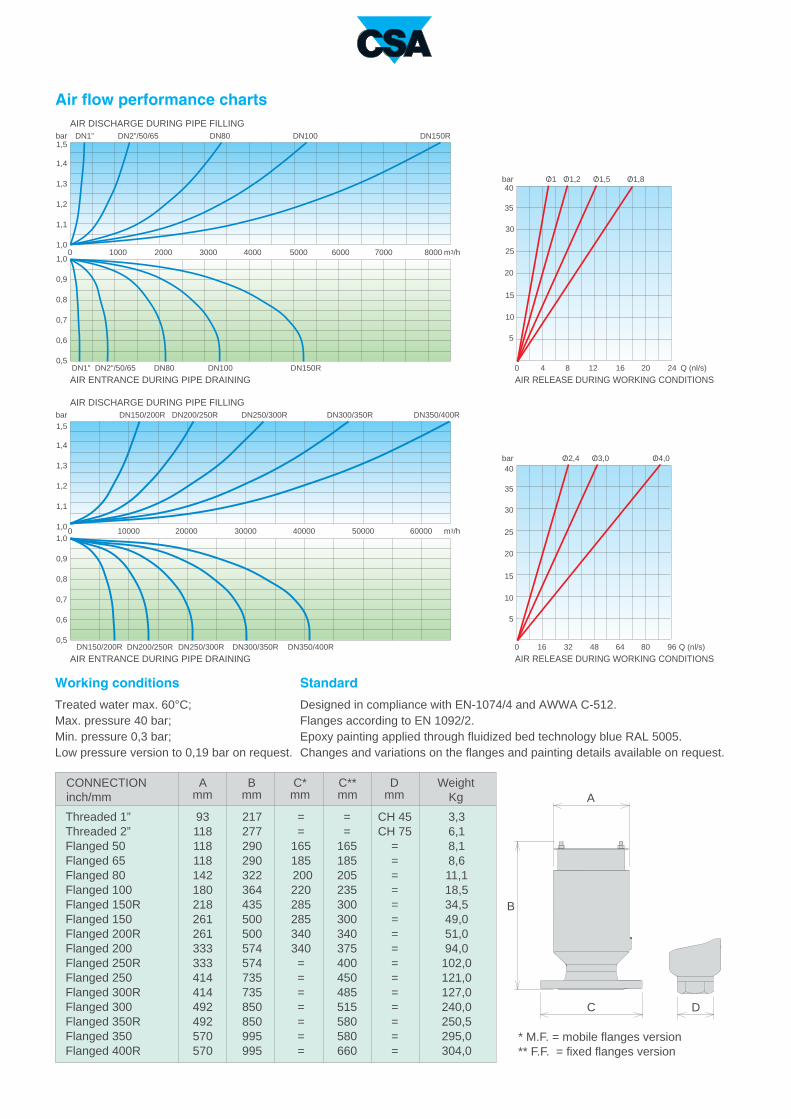
Working conditions
Treated water max. 60°C;
Max. pressure 40 bar;
Min. pressure 0,3 bar;
Low pressure version to 0,19 bar on request.
Standard
Designed in compliance with EN-1074/4 and AWWA C-512.
Flanges according to EN 1092/2.
Epoxy painting applied through fluidized bed technology blue RAL 5005.
Changes and variations on the flanges and painting details available on request.
AIR RELEASE DURING WORKING CONDITIONS
AIR RELEASE DURING WORKING CONDITIONS
* M.F. = mobile flanges version
** F.F. = fixed flanges version
AIR ENTRANCE DURING PIPE DRAINING
AIR DISCHARGE DURING PIPE FILLING
Air flow performance chartsAIR DISCHARGE DURING PIPE FILLING
AIR ENTRANCE DURING PIPE DRAINING
Weight
Kg
CONNECTION
inch/mm
Threaded 1”
Threaded 2”
Flanged 50
Flanged 65
Flanged 80
Flanged 100
Flanged 150R
Flanged 150
Flanged 200R
Flanged 200
Flanged 250R
Flanged 250
Flanged 300R
Flanged 300
Flanged 350R
Flanged 350
Flanged 400R
14
6
2
16
5
3
7
15
11
1
8
12
9
4
10
13
N.
1
2
3
4
5
6
7
8
9
10
11
12
13
14
15
16
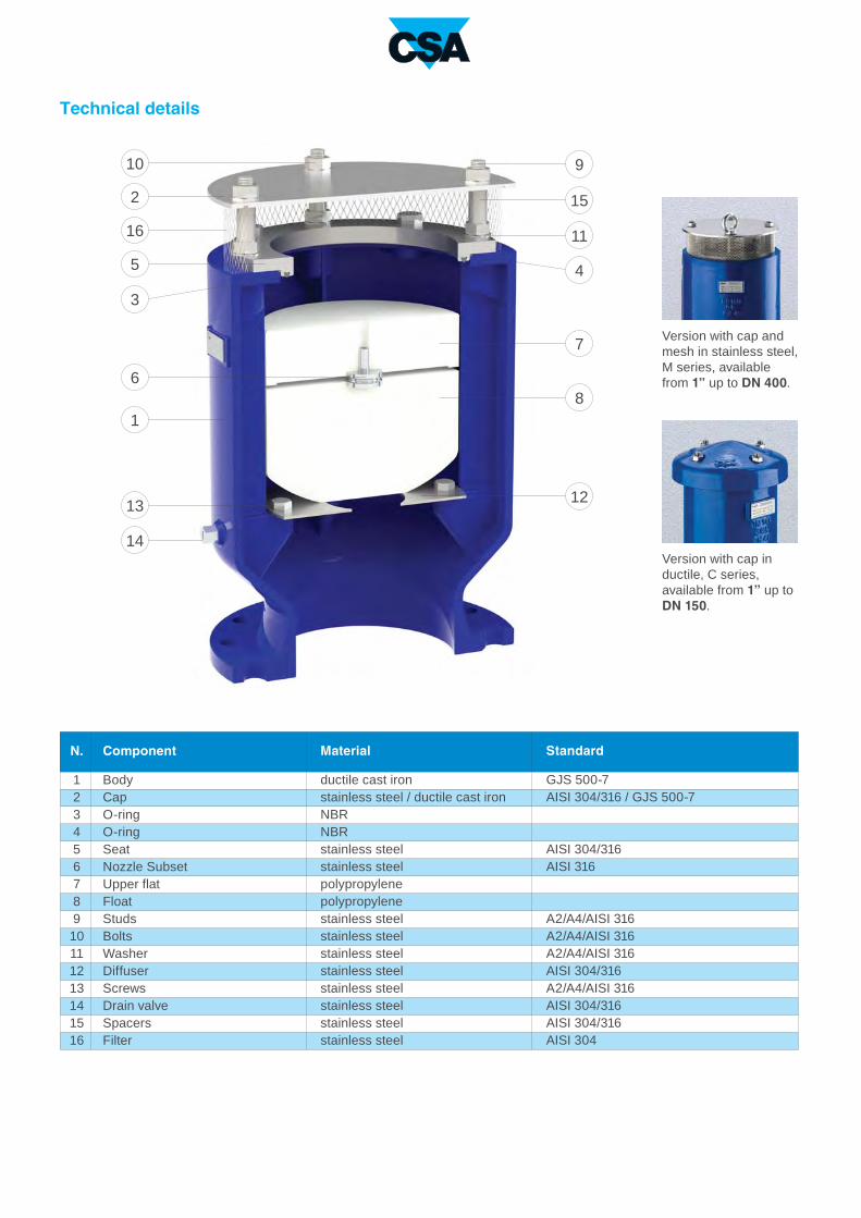
Version with cap in
ductile, C series,
available from 1” up to
DN 150.
Version with cap and
mesh in stainless steel,
M series, available
from 1” up to DN 400.
Technical details
Component
Body
Cap
O-ring
O-ring
Seat
Nozzle Subset
Upper flat
Float
Studs
Bolts
Washer
Diffuser
Screws
Drain valve
Spacers
Filter
Material
ductile cast iron
stainless steel / ductile cast iron
NBR
NBR
stainless steel
stainless steel
polypropylene
polypropylene
stainless steel
stainless steel
stainless steel
stainless steel
stainless steel
stainless steel
stainless steel
stainless steel
Standard
GJS 500-7
AISI 304/316 / GJS 500-7
AISI 304/316
AISI 316
A2/A4/AISI 316
A2/A4/AISI 316
A2/A4/AISI 316
AISI 304/316
A2/A4/AISI 316
AISI 304/316
AISI 304/316
AISI 304

The CSA air valve Mod. FOX 3F AS will ensure the proper operation of the pipeline network allowing the
release of air pockets during working conditions, the entrance of large volumes of air during draining
operations and pipeline bursts and the air discharge with controlled speed, to prevent water hammer.
Anti water hammer combination air valve Mod. FOX 3F - AS
Technical features and benefits
■ Body in ductile cast iron, PN 40 bar rated, provided with internal ribs for consistent and accurate guiding
of the mobile block.
■ Drainage valve produced by CSA, for chamber control and pressure relief during maintenance.
■ Mobile block composed of a cylindrical float and upper disk in solid polypropylene, joined together by the
CSA air release system in AISI 316 (pat. Pending). The solid cylindrical floats, obtained by CNC
machining only , avoid deformations and ensure a great sliding precision inside the body processed ribs
and a perfectly vertical thrust.
■ Nozzle and gasket holder, part of CSA air release system, entirely made in AISI 316 and designed with
gasket compression control to prevent aging process and consequent leakage during working
conditions.
■ Maintenance can be easily performed from the top, without removing the air valve from the pipe.
■ Anti water hammer system (also called AS function), never in contact with water, obtained by a spring and
shaft in stainless steel, disk with adjustable sonic nozzles for air flow control.
Applications
■ Main transmission lines.
■ Water distribution networks.
■ Irrigation systems.
■ In general this model is used near pumps, on changes in slope ascending, and at the high points of the
pipeline subjected to water hammer.

Operating principle
Optional
■ Vacuum breaker version Mod. FOX 2F AS, to allow the entrance of large volumes of air and
the controlled outflow only. This model is normally recommended in changes in slope ascen-
ding, long ascending segments, dry fire systems.
■ Version for submerged applications, SUB series, available both for FOX 3F AS and 2F AS
Models, with elbow for air conveyance. The design sprang from the necessity of having an air
valve performing also in case of flood, without the risk of contaminated water entering the pipeli-
ne. Another benefit of SUB is to avoid the spray effect, conveying spurts coming from the closu-
re away from the air valve.
■ The counteracting spring force as well as the sonic nozzles, both responsible of the proper
operation of the AS device, can be modified on request according to the project conditions and
the transient analysis.
Controlled air discharge
During the pipe filling it is neces-
sary to avoid rapid closures,
responsible of water hammer
effects. The FOX 3F AS, thanks
to the anti-shock feature, will
control the air outflow thus redu-
cing the velocity of the approa-
ching water column. The risk of
overpressure will therefore be
minimized.
Air release during working conditions
During operation the air produ-
ced by the pipeline is accumula-
ted in the upper part of the air
valve. Little by little it is com-
pressed and the pressure
arrives to water pressure, there-
fore i ts volume increases
push ing the water leve l
downwards allowing the air
release through the nozzle.
Entrance of largevolumes of air
During pipeline draining, or pipe
bursts, it is necessary to bring in
as much air as the quantity of
outflowing water to avoid negati-
ve pressure and serious dama-
ges of the pipeline, and to the
entire system.

0 1000 2000 30001500500 2500 3500 4000 m3/h
0 50 150 250100 200 300 350 m3/h
1,0
1,1
1,2
1,3
1,4
1,5
DN1”
0 8000 16000 24000120004000 20000 28000 32000 m3/h
0 1000 2000500 1500 2500 3000 m3/h
0,5
0,6
0,7
0,8
0,9
1,0
DN80 DN100
DN80 DN100DN1” DN150R
DN150R
1,0
1,1
1,2
1,3
1,4
1,5
0,5
0,6
0,7
0,8
0,9
1,0
DC
A
B
bar
bar
Q (nl/s)
10
5
124 8 16 20 24
20
25
30
15
35
40
10
5
20
25
30
15
35
40
bar O1,2/O1/ O1,5/ O1,8/
4816 32 64 80 96
O2,4/ O3,0/ O4,0/bar
Q (nl/s)
0
0
DN2”/50/65
DN2”/50/65
DN300/350R DN350/400RDN150/200R DN200/250R DN250/300R
DN300/350R DN350/400RDN150/200R DN200/250R DN250/300R
A
mm
B
mm
C**
mm
C*
mm
D
mm
93 217 = = CH 45 3,3
118 277 = = CH 75 6,1
118 290 165 165 = 8,1
118 290 185 185 = 8,6
142 322 200 205 = 11,1
180 364 220 235 = 18,5
218 435 285 300 = 34,5
261 500 285 300 = 49,0
261 500 340 340 = 51,0
333 596 340 375 = 94,0
333 596 = 400 = 102,0
414 735 = 450 = 121,0
414 735 = 485 = 127,0
492 850 = 515 = 240,0
492 850 = 580 = 250,5
570 995 = 580 = 295,0
570 995 = 660 = 304,0
Working conditions
Treated water max. 60°C;
Max. pressure 40 bar;
Min. pressure 0,3 bar;
Low pressure version to 0,19 bar on request.
Standard
Designed in compliance with EN-1074/4 and AWWA C-512.
Flanges according to EN 1092/2.
Epoxy painting applies through fluidized bed technology blue RAL 5005.
Changes and variations on the flanges and painting details available on request.
* M.F. = mobile flanges version
** F.F. = fixed flanges version
AIR RELEASE DURING WORKING CONDITIONS
AIR RELEASE DURING WORKING CONDITIONS
AIR ENTRANCE DURING PIPE DRAINING
AIR DISCHARGE DURING PIPE FILLING
Air flow performance chartsAIR DISCHARGE DURING PIPE FILLING
AIR ENTRANCE DURING PIPE DRAINING
Weight
Kg
CONNECTION
inch/mm
Threaded 1”
Threaded 2”
Flanged 50
Flanged 65
Flanged 80
Flanged 100
Flanged 150R
Flanged 150
Flanged 200R
Flanged 200
Flanged 250R
Flanged 250
Flanged 300R
Flanged 300
Flanged 350R
Flanged 350
Flanged 400R

14
3
2
19
16
20
21
22
5
7
4
17
10
18
15
11
1
8
6
12
9
13
N.
1
2
3
4
5
6
7
8
9
10
11
12
13
14
15
16
17
18
19
20
21
22
Technical details
Component
Body
Cap
O-ring
O-ring
Seat
Nozzle subset
Upper flat
Float
Studs
Nuts
Washer
Diffuser
Screws
Drainage valve
Spacers
Filter
Nut
Spring
AS shaft
Guiding plate (from DN150R)
Guiding nut (from DN150R)
AS flat
Material
ductile cast iron
stainless steel / ductile cast iron
NBR
NBR
stainless steel
stainless steel
polypropylene
polypropylene
stainless steel
stainless steel
stainless steel
stainless steel
stainless steel
stainless steel
stainless steel
stainless steel
stainless steel
stainless steel
stainless steel
stainless steel
stainless steel
stainless steel
Standard
GJS 500-7
AISI 304/316 / GJS 500-7
AISI 304/316
AISI 304/316
A2/A4
A2/A4
A2/A4
AISI 304/316
A2/A4
AISI 304/316
AISI 304/316
AISI 304
AISI 304/316
AISI 304/316
AISI 304/316
AISI 304/316
AISI 304/316
AISI 304/316
Version with cap in
ductile, C series,
available from 1” up to
DN 150.
Version with cap and
mesh in stainless steel,
M series, available
from 1” up to DN 400.

The CSA air valve Mod. FOX 3F RFP will ensure the proper operation of the system allowing the release
of air pockets during working conditions and the entrance of large volumes of air during draining. In addition
to that this model will always maintain the air outflow within a safety limit, without the risk of water hammer.
Combination air valve with rapid fillingpreventer mechanism Mod. FOX 3F - RFP
Technical features and benefits
■ Uncontrolled pipeline filling operations and transient events will inevitably generate the rapid closure of
the air valves installed along the system, with consequent damages. The CSA air valve FOX 3F RFP will
automatically adjust the outflow capacity, thus reducing the velocity of the incoming water column
minimizing the risk of water hammer.
■ The spray effect during closure and the risk of air valve drowning, due to low pressure and possible rapid
filling, is avoided.
■ Body in ductile cast iron, PN 40 bar rated, provided with internal ribs for consistent and accurate guiding
of the mobile block.
■ Mobile block composed of the main float and upper disk, joined together by the CSA air release system
in AISI 316 (pat. pending), and an additional anti surge obturator.
■ Nozzle and gasket holder, part of CSA air release system, entirely made in AISI 316 and designed with
gasket compression control to prevent aging process and consequent leakage during working
conditions.
Applications
■ Main transmission lines.
■ Water distribution networks.
■ Irrigation systems.
■ In general this model is used, in combination with CSA AS technology, on changes in slope and high
points of the profile to provide the best air control and safety of the pipeline.

Operating principle
Optional
■ Vacuum breaker version Mod. FOX 2F RFP, to allow the entrance of large volumes of air
and the controlled outflow only. This model is normally recommended in changes in slope
ascending, long ascending segments, dry fire systems, and wherever the water hammer effect
has to be reduced without the necessity of air release.
■ Version for submerged applications, SUB series, available both for FOX 3F RFP and 2F
RFP Models, with elbow for air conveyance. The design sprang from the necessity of having an
air valve performing also in case of flood, without the risk of contaminated water entering the
pipeline. Another benefit of SUB is to avoid the spray effect, conveying spurts coming from the
closure away from the air valve.
■ Version for air discharge only EO series, available both for FOX 3F and 2F models. The
most important application of EO is to allow the air valve installation in those locations of the
system where HGL may drop below the pipe profile, and to any other node where for project
requirements air entrance must be avoided.
Discharge of large volumes of air
During the pipe filling it is
necessary to discharge
air as water flows in. The
FOX 3F RFP, thanks to
an aerodynamic full port
body and deflector, will
make sure to avo id
premature closures of the
mobile block during this
phase.
Controlled outflow
If the differential pressure
of air, during pipe filling,
i nc reases above a
cer tain value without
control there is the risk of
wa te r hammer and
damages to the system.
Should that happen the
RFP upper float will rise
automatically, reducing
the outflow and conse-
quently the velocity of the
approach ing water
column.
Air release during working conditions
During operation the
air produced by the
pipeline is accumulated
in the upper part of the
air valve. Little by little it
is compressed and the
pressure arrives to water
pressure, therefore
its volume increases
pushing the water level
downwards allowing the
air release through the
nozzle.
Entrance of large volumes of air
During pipeline draining,
or p ipe burs ts , i t i s
necessary to bring in as
much air as the quantity
of outflowing water to
avoid negative pressure
and serious damages of
the pipeline, and to the
entire system.

0 100 250 500 1000 2500 5000 10000 25000 50000 100000 m3/h1,0
1,1
1,2
1,3
1,4
1,5
0,5
0,6
0,7
0,8
0,9
1,0
0 101 20 30 50 100 200 300 500 1000 2000 50003000 10000 m3/h
1,0
1,1
1,2
1,3
1,4
1,5
DN80 DN100DN1” DN150R
0,5
0,6
0,7
0,8
0,9
1,0
DN80 DN100DN1” DN150R
DC
A
B
bar
bar
Q (nl/s)
10
5
124 8 16 20 24
20
25
30
15
35
40
10
5
20
25
30
15
35
40
bar O1,2/O1/ O1,5/ O1,8/
4816 32 64 80 96
O2,4/ O3,0/ O4,0/bar
Q (nl/s)
0
0
DN2”/50/65
DN2”/50/65
DN200
/250R
DN250
/300R
DN300
/350R
DN350
/400R
DN150
/200R
DN200
/250R
DN250
/300R
DN300
/350R
DN350
/400R
DN150
/200R
A
mm
B
mm
C**
mm
C*
mm
D
mm
93 217 = = CH 45 3,3
118 277 = = CH 75 6,1
118 290 165 165 = 8,1
118 290 185 185 = 8,6
142 322 200 205 = 11,1
180 364 220 235 = 18,5
218 435 285 300 = 34,5
261 500 285 300 = 49,0
261 500 340 340 = 51,0
333 574 340 375 = 94,0
333 574 = 400 = 102,0
414 735 = 450 = 121,0
414 735 = 485 = 127,0
492 850 = 515 = 240,0
492 850 = 580 = 250,5
570 995 = 580 = 295,0
570 995 = 660 = 304,0
Working conditions
Treated water max. 60°C;
Max. pressure 40 bar;
Min. pressure 0,3 bar;
Low pressure version to 0,19 bar on request.
Standard
Designed in compliance with EN-1074/4 and AWWA C-512.
Flanges according to EN 1092/2.
Epoxy painting applies through fluidized bed technology blue RAL 5005.
Changes and variations on the flanges and painting details available on request.
* M.F. = mobile flanges version
** F.F. = fixed flanges version
AIR RELEASE DURING WORKING CONDITIONS
AIR RELEASE DURING WORKING CONDITIONS
AIR ENTRANCE DURING PIPE DRAINING
AIR DISCHARGE DURING PIPE FILLING
Air flow performance chartsAIR DISCHARGE DURING PIPE FILLING
AIR ENTRANCE DURING PIPE DRAINING
Weight
Kg
CONNECTION
inch/mm
Threaded 1”
Threaded 2”
Flanged 50
Flanged 65
Flanged 80
Flanged 100
Flanged 150R
Flanged 150
Flanged 200R
Flanged 200
Flanged 250R
Flanged 250
Flanged 300R
Flanged 300
Flanged 350R
Flanged 350
Flanged 400R

15
6
2
17
5
3
8
7
16
12
1
9
13
10
4
11
14
N.
1
2
3
4
5
6
7
8
9
10
11
12
13
14
15
16
17
Technical details
Component
Body
Cap
O-ring
O-ring
Seat
Nozzle Subset
RFP flat
Upper flat
Float
Studs
Bolts
Washers
Diffuser
Screws
Drain valve
Spacers
Filter
Material
ductile cast iron
stainless steel / ductile cast iron
NBR
NBR
stainless steel
stainless steel
polypropylene
polypropylene
polypropylene
stainless steel
stainless steel
stainless steel
stainless steel
stainless steel
stainless steel
stainless steel
stainless steel
Standard
GJS 500-7
AISI 304/316 / GJS 500-7
AISI 304/316
AISI 304/316
A2/A4
A2/A4
A2/A4
AISI 304/316
A2/A4
AISI 304/316
AISI 304/316
AISI 304
Version with cap in
ductile, C series,
available from 1” up to
DN 150.
Version with cap and
mesh in stainless steel,
M series, available
from 1” up to DN 400.

The CSA air valve Mod. FOX 3F HP will ensure the proper operation of the pipeline network allowing the
release of air pockets during working conditions, the evacuation and entrance of large volumes of air during
filling and draining operations.
Combination air valve Mod. FOX 3F - HP
Technical features and benefits
■ Body in carbon welded steel, PN 64 bar rated, provided with internal spacers for consistent and accurate
guiding of the mobile block.
■ In general supplied with fixed flanges according to EN 1092/2 or different on request.
■ Mobile block composed of a cylindrical float and upper disk in solid polypropylene, joined together by the
CSA air release system in AISI 316 (pat. Pending). The solid cylindrical floats, obtained by CNC
machining, avoid deformations and ensure a great sliding precision inside the body processed ribs and
a perfectly vertical thrust.
■ Nozzle and gasket holder, part of CSA air release system, entirely made in AISI 316 and designed with
gasket compression control to prevent aging process and consequent leakage during working
conditions.
■ Maintenance can be easily performed from the top, without removing the air valve from the pipe.
■ Mesh and cap in stainless steel.
Applications
■ Main transmission lines.
■ Mines.
■ Dams and high pressure systems
■ In general this model is used on changes in slope descending and at the high points of the pipeline for
those locations exposed to high pressure conditions when ductile cast iron is not acceptable.

Operating principle
Discharge of largevolumes of air
During the pipe filling it is neces-
sary to discharge air as water
flows in. The FOX 3F HP, thanks
to an aerodynamic deflector, will
make sure to avoid premature
closures of the mobile block
during this phase.
Air release during working conditions
During operation the air produ-
ced by the pipeline is accumula-
ted in the upper part of the air
valve. Little by little it is com-
pressed and the pressure
arrives to water pressure, there-
fore i ts volume increases
push ing the water leve l
downwards allowing the air
release through the nozzle.
Optional
■ Vacuum breaker version Mod. FOX 2F HP to allow the entrance and discharge of large
volumes of air only. This model is normally recommended in changes in slope ascending, long
ascending segments, dry fire systems, and wherever the air release won’t be required.
■ Version for submerged applications, SUB series, available both for FOX 3F HP and 2F HP
Models, with elbow for air conveyance. The design sprang from the necessity of having an air
valve performing also in case of flood, without the risk of contaminated water entering the pipeli-
ne. Another benefit of SUB is to avoid the spray effect, conveying spurts coming from the rapid
closure of the air valve.
■ Version for air discharge only EO series, available both for FOX 3F HP and 2F HP models.
The most important application of EO is to allow the air valve installation in those locations of
the system where HGL may drop below the pipe profile, and to any other node where for project
requirements air entrance must be avoided.
■ Version for air entrance only IO series, available for FOX 2F HP model only. The most
important application of IO is to allow the air valve installation in those locations of the system
where, for project requirements, air discharge and release must be avoided.
Entrance of largevolumes of air
During pipeline draining, or pipe
bursts, it is necessary to bring in
as much air as the quantity of
outflowing water to avoid negati-
ve pressure and serious dama-
ges of the pipeline, and to the
entire system.

C
A
B
0,7
0,75
0,8
0,85
0,9
0,95
1
1
1,05
1,1
1,15
1,2
1,25
1,3
BAR
BAR
1,35
1,4
1,45
1,5
0,5
0,55
0,6
0,65
0,7
0,75
0,8
0,85
0,9
0,95
1,05
1,1
1,15
1,2
1,25
1,3
BAR
BAR
1,35
1,4
1,45
1,5
0,5
0,55
0,6
0,65
m3/h2000 4000 6000 800010000 3000 5000 7000
185
200 265
240 180
205 9,2
165 240 180 4,2
165 240 180 6,0
235 334 205 13,0
6,0
165 240 180 5,0
300 380 250 35,0
DN2”/50/65 DN80 DN100DN1” DN150
DN2”/50/65 DN80 DN100DN1” DN150
A
mm
B
mm
C
mm
10
120 4 8 16 20 24 28 Q (nl/s)32
20
30
40
50
60
64
bar O1,2/O1/ O1,5/ O1,8/Working conditions
Treated water 70° C max.;
Maximum pressure 64 bar;
Minimum pressure 0,2 bar;
Standard
Designed in compliance with EN-1074/4.
Flanges according to EN 1092/2, ANSI.
Epoxy painting applied through fluidized bed technology
blue RAL 5005.
Changes and variations on the flanges and painting details
available on request.
AIR DISCHARGE DURING PIPE FILLING
AIR ENTRANCE DURING PIPE DRAINING
Air flow performance charts
Weight
Kg
CONNECTION
inch/mm
Flanged 80
Flanged 65
Threaded 1”
Flanged 50
Flanged 100
Threaded 2”
Flanged 150
AIR RELEASE DURING WORKING CONDITIONS

13
2
4
9
7
6
8
15
14
1
5
3
12
11
10
N.
1
2
3
4
5
6
7
8
9
10
11
12
13
14
15
Technical details
Component
Body
Cap
O-ring
O-ring
Seat
Nozzle Subset
Upper flat
Float
Nut
Washers
Screws
Screws
Drain valve
Spacers
Filter
Material
steel
stainless steel
NBR
NBR
stainless steel
stainless steel
polypropylene
polypropylene
stainless steel
stainless steel
stainless steel
stainless steel
stainless steel
stainless steel
stainless steel
Standard
Fe 37
AISI 304/316
AISI 304/316
AISI 316
A2/A4/AISI 316
A2/A4/AISI 316
A2/A4/AISI 316
A2/A4/AISI 316
AISI 304/316
AISI 304/316
AISI 304

Anti water hammer combination air valve Mod. FOX 3F - AS - HP
The CSA air valve Mod. FOX 3F AS HP will ensure the proper operation of the pipeline network allowing
the release of air pockets during working conditions, the entrance of large volumes of air during draining
operations and pipeline bursts and the air discharge with controlled speed, to prevent water hammer.
Technical features and benefits
■ Body in carbon welded steel, PN 64 bar rated, provided with internal spacers for consistent and accurate
guiding of the mobile block.
■ In general supplied with fixed flanges according to EN 1092/2 or different on request.
■ Mobile block composed of a cylindrical float and upper disk in solid polypropylene, joined together by the
CSA air release system in AISI 316 (pat. Pending). The solid cylindrical floats, obtained by CNC
machining only, avoid deformations and ensure a great sliding precision inside the body processed ribs
and a perfectly vertical thrust.
■ Nozzle and gasket holder, part of CSA air release system, entirely made in AISI 316 and designed with
gasket compression control to prevent aging process and consequent leakage during working
conditions.
■ Maintenance can be easily performed from the top, without removing the air valve from the pipe.
■ Anti water hammer system (also called AS function), never in contact with water, obtained by a spring and
shaft in stainless steel, disk with adjustable sonic nozzles for air flow control.
Applications
■ Main transmission lines.
■ Mines.
■ Dams and high pressure systems.
■ In general this model is used on changes in slope ascending, and at the high points of the pipeline
subjected to water hammer.

Operating principle
Optional
■ Vacuum breaker version Mod. FOX 2F AS HP, to allow the entrance of large volumes of air
and the controlled outflow only. This model is normally recommended in changes in slope
ascending, long ascending segments, dry fire systems.
■ Version for submerged applications, SUB series, available both for FOX 3F AS HP and
2F AS HP Models, with elbow for air conveyance. The design sprang from the necessity of
having an air valve performing also in case of flood, without the risk of contaminated water ente-
ring the pipeline. Another benefit of SUB is to avoid the spray effect, conveying spurts coming
from the closure away from the air valve.
■ The counteracting spring force as well as the sonic nozzles, both responsible of the proper
operation of the AS device, can be modified on request according to the project conditions and
the transient analysis.
Controlled air discharge
During the pipe filling it is neces-
sary to avoid rapid closures, re-
sponsible of water hammer ef-
fects. The FOX 3F AS HP,
thanks to the anti-shock feature,
will control the air outflow thus
reducing the velocity of the ap-
proaching water column. The
risk of overpressure will therefo-
re be minimized.
Air release during working conditions
During operation the air produ-
ced by the pipeline is accumula-
ted in the upper part of the air
valve. Little by little it is com-
pressed and the pressure
arrives to water pressure, there-
fore i ts volume increases
push ing the water leve l
downwards allowing the air
release through the nozzle.
Entrance of largevolumes of air
During pipeline draining, or pipe
bursts, it is necessary to bring in
as much air as the quantity of
outflowing water to avoid negati-
ve pressure and serious dama-
ges of the pipeline, and to the
entire system.

C
A
B
0,7
0,75
0,8
0,85
0,9
0,95
1
1
1,05
1,1
1,15
1,2
1,25
1,3
BAR
BAR
1,35
1,4
1,45
1,5
0,5
0,55
0,6
0,65
0,7
0,75
0,8
0,85
0,9
0,95
1,05
1,1
1,15
1,2
1,25
1,3
BAR
BAR
1,35
1,4
1,45
1,5
0,5
0,55
0,6
0,65
m3/h100 200 300 350500 150 250
m3/h1000 2000 3000 40005000 1500 2500 3500
185
200 265
240 180
205 9,2
165 240 180 4,2
165 240 180 6,0
235 334 205 13,0
6,0
165 240 180 5,0
300 380 250 35,0
DN2”/50/65 DN80 DN100DN1” DN150
DN2”/50/65 DN80 DN100DN1” DN150
A
mm
B
mm
C
mm
10
120 4 8 16 20 24 28 Q (nl/s)32
20
30
40
50
60
64
bar O1,2/O1/ O1,5/ O1,8/Working conditions
Treated water 70° C max.;
Maximum pressure 64 bar;
Minimum pressure 0,2 bar;
Standard
Designed in compliance with EN-1074/4.
Flanges according to EN 1092/2, ANSI.
Epoxy painting applied through fluidized bed technology
blue RAL 5005.
Changes and variations on the flanges and painting details
available on request.
AIR DISCHARGE DURING PIPE FILLING
AIR ENTRANCE DURING PIPE DRAINING
Air flow performance charts
Weight
Kg
CONNECTION
inch/mm
Flanged 80
Flanged 65
Threaded 1”
Flanged 50
Flanged 100
Threaded 2”
Flanged 150
AIR RELEASE DURING WORKING CONDITIONS

N.
1
2
3
4
5
6
7
8
9
10
11
12
13
14
15
16
17
18
19
20
4
3
1
5
7
6
8
2
11
17
15
14
18
10
9
13
16
19
20
12
Technical details
Component
Body
Cap
O-ring
O-ring
Seat
Nozzle subset
Upper flat
Float
Screws
Nuts
Washer
Screws
Spacers
Filter
Nut
Spring
AS shaft
Guiding plate (in DN150)
Guiding nut (in DN150)
AS flat
Material
steel
stainless steel
NBR
NBR
stainless steel
stainless steel
polypropylene
polypropylene
stainless steel
stainless steel
stainless steel
stainless steel
stainless steel
stainless steel
stainless steel
stainless steel
stainless steel
stainless steel
stainless steel
stainless steel
Standard
Fe 37
AISI 304/316
AISI 304/316
AISI 304/316
A2/A4/AISI 316
A2/A4/AISI 316
A2/A4/AISI 316
A2/A4/AISI 316
AISI 304/316
AISI 304
AISI 304/316
AISI 304/316
AISI 304/316
AISI 304/316
AISI 304/316
AISI 304/316

Technical features and benefits
■ Body and cover in ductile cast iron, PN 40 bar rated.
■ Float in stainless steel AISI 304/316.
■ Lever and pivots in AISI 304/316.
■ Nozzle in stainless steel AISI 304/316.
■ Compass lever technology to allow large air release capacity through the nozzle.
■ Double o-ring to guarantee the perfect water tightness during working conditions.
■ Gasket compression control thanks to the adjustable nozzle.
■ Nuts and bolts in stainless steel A2/ AISI 316.
■ Minimum working pressure 0,1 bar.
Applications
■ Water distribution systems, irrigation, buildings.
■ Pumps case.
■ Control valves and modulating devices.
■ In general only when the air release function is required, it can be combined with CSA air valves FOX
series for the kinetic functions of air outflow and inflow.
The CSA air release valve Ventolo will ensure the proper operation of the system allowing the release of
air pockets accumulating during working conditions.
Air release valve Mod. VENTOLO

N.
1
2
3
4
5
6
7
8
9
10
11
12
13
14
15
2
13
3
12
9
1
5
4
6
7
8
10
11
6
5
0 2 4 71 3 5
15
20
25
10
8 Q (nl/s)
30
35
40p (bar)
O1,7/
O1,1/
1514
Standard
14
5
123
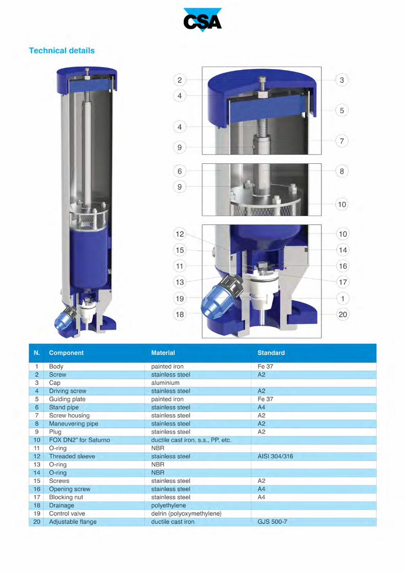
Technical details
Component
Body
Cap
O-ring
Nozzle
Nut
O-ring
Upper lever
Pivot
Lower lever
Nozzle gasket
Float
Nut
Screw
Ball valve
Flange
Material
ductile cast iron
ductile cast iron
NBR
stainless steel
stainless steel
NBR
stainless steel
stainless steel
stainless steel
NBR
stainless steel
stainless steel
stainless steel
stainless steel
ductile cast iron
Standard
GJS 500-7
GJS 500-7
AISI 304/316
AISI 304/316
AISI 304/316
AISI 304/316
AISI 304/316
AISI 316
AISI 304/316
AISI 304/316
AISI 316
GJS 500-7
AIR RELEASE DURING
WORKING CONDITIONS
Treated water max. 70°C;
Max. pressure 40 bar;
Min. pressure 0,1 bar.
Designed in compliance with EN-1074/4.
Standard connection 1”, flanged on request. Flanges according to EN 1092/2.
Epoxy painting applies through fluidized bed technology blue RAL 5005.
Changes and variations on the flanges and painting details available on request.
Air flow performance charts
Working conditions

The CSA combination air valve Eolo will ensure the proper operation of the system allowing the release of
air pockets accumulating during working conditions, the entrance and discharge of large volumes of air
during pipe draining and filling.
Combination air valve Mod. EOLO
Technical features and benefits
■ Upper and lower bodies in ductile cast iron GJS 500/7 PN 25 rated.
■ Float in stainless steel AISI 304 covered with vulcanized NBR.
■ Patented air release system with gasket compression control in brass/stainless steel AISI 304.
■ Guiding shaft of the air release system in stainless steel AISI 304.
■ Nuts and bolts in stainless steel A/2.
■ Simple and compact.
Applications
■ Water distribution systems.
■ Irrigation, cooling systems.
■ Buildings.
■ In general where the air release function is necessary along with a certain air flow capacity, limited to the
kinetic passage of this model for which please see the air charts on the next page.

N.
1
2
3
4
5
6
7
8
9
10
11
12
13
1312
142
22
0
Q (nl/s)
10
5
0 4 82 6 10
20
25
15
p (bar)
O1,5/
3
8
6
10
11
11
4
5
9
2
11
1
7
82
78
∆ p (bar) 0,1
106
90
0,2
120
118
0,3
127
128
125
133
0,4 0,5
Standard
Technical details
AIR RELEASE DURING
WORKING CONDITIONS
AIR DISCHARGE AND ENTRANCE
DURING PIPE FILLING AND DRAINING
Component
Lower body
Upper body
O-ring
Float
Nozzle body
O-ring
Tap
Shaft
Studs
O-ring
Screws, washers and bots
Ball valve
Flange
Material
ductile cast iron
ductile cast iron
NBR
stainless steel/NBR
brass/stainless steel
NBR
brass/stainless steel
stainless steel
brass
NBR
stainless steel
stainless steel
ductile cast iron
Standard
GJS 500-7
GJS 500-7
AISI 316
OT 58/AISI 304/316
OT 58/AISI 304/316
AISI 304/316
OT 58
AISI 304/316
AISI 316
GJS 500-7
Treated water max. 70°C,
higher temperature on request;
Max. pressure 25 bar;
Min. pressure 0,3 bar.
Air flow performance charts
Designed in compliance with EN-1074/4.
Standard connection 1”, flanged on request. Flanges according to EN 1092/2.
Epoxy painting applies through fluidized bed technology blue RAL 5005.
Changes and variations on the flanges and painting details available on request.
Air discharge (m3/h)
AIr entrance (m3/h)
Working conditions
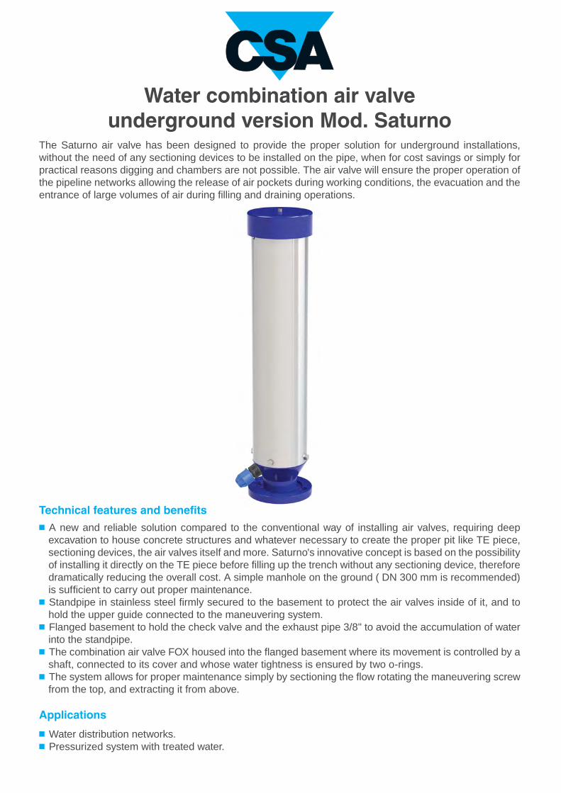
The Saturno air valve has been designed to provide the proper solution for underground installations,
without the need of any sectioning devices to be installed on the pipe, when for cost savings or simply for
practical reasons digging and chambers are not possible. The air valve will ensure the proper operation of
the pipeline networks allowing the release of air pockets during working conditions, the evacuation and the
entrance of large volumes of air during filling and draining operations.
Water combination air valveunderground version Mod. Saturno
Technical features and benefits
■ A new and reliable solution compared to the conventional way of installing air valves, requiring deep
excavation to house concrete structures and whatever necessary to create the proper pit like TE piece,
sectioning devices, the air valves itself and more. Saturno's innovative concept is based on the possibility
of installing it directly on the TE piece before filling up the trench without any sectioning device, therefore
dramatically reducing the overall cost. A simple manhole on the ground ( DN 300 mm is recommended)
is sufficient to carry out proper maintenance.
■ Standpipe in stainless steel firmly secured to the basement to protect the air valves inside of it, and to
hold the upper guide connected to the maneuvering system.
■ Flanged basement to hold the check valve and the exhaust pipe 3/8" to avoid the accumulation of water
into the standpipe.
■ The combination air valve FOX housed into the flanged basement where its movement is controlled by a
shaft, connected to its cover and whose water tightness is ensured by two o-rings.
■ The system allows for proper maintenance simply by sectioning the flow rotating the maneuvering screw
from the top, and extracting it from above.
Applications
■ Water distribution networks.
■ Pressurized system with treated water.

Operating principle
1. Discharge of large volumes of air
During the pipe filling it is necessary to
discharge air as water flows in. The FOX 3F,
thanks to an aerodynamic full port body and
deflector, will make sure to avoid premature
closures of the mobile bloc k during this
phase.
1 2 3
2. Air release during working conditions
During operation the air produced by the
pipeline is accumulated in the upper part of
the air valve. Little by little it is compressed
and the pressure arrives to water pressure,
therefore its volume increases pushing the
water level downwards allowing the air relea-
se through the nozzle.
3. Entrance of large volumes of air
During pipeline draining, or pipe bursts, it is
necessary to bring in as much air as the
quantity of outflowing water to avoid negative
pressure and serious damages of the pipeli-
ne, and to the entire system.
Installation
The installation of Saturno simply
requires a derivation from the
main pipe, a manhole on top to
allow for maintenance opera-
tions. The picture depicts the
proper installation where the
drain port plays a fundamental
role, allowing for the water
discharge from the main pipe.
Normally supplied with 3/8”
connection it should be positio-
ned within a layer of small stones
to facilitate the draining.
Air valve removal
The design of the underground
air valve Saturno allows for a
maintenance and replacement
without removing the air valve
from the pipe, simply acting on
the cap and maneuvering key
from above as shown on the
picture on the right. All the com-
ponents will be pulled out from
the top without the need of
digging and further operations.

CD
A
B
0,7
0,75
0,8
0,85
0,9
0,95
1
1
1,05
1,1
1,15
1,2
1,25
1,3
BAR
BAR
1,35
1,4
1,45
1,5
0,5
0,55
0,6
0,65
0,7
0,75
0,8
0,85
0,9
0,95
1,05
1,1
1,15
1,2
1,25
1,3
BAR
BAR
1,35
1,4
1,45
1,5
0,5
0,55
0,6
0,65
m3/h600 800 1000 15005004003002001000 700 900 1100 1200 1300 1400
Q (nl/s)
10
5
124 8 16 20 24
20
25
30
15
35
40
bar O1,2/O1/ O1,5/ O1,8/
0
DN
mm
A
mm
B
mm
C
mm
D
mm
160 750 82,5
82,5
82,5
82,5
122,5
122,5
122,5
122,5
122,5
122,5
122,5
122,5
160 1000
160 1250
50
160 1500
160 750 100
100
100
100
160 1000
160 1250
80
160 1500
20,5
23,2
25,3
28,6
22,0
24,7
26,8
30,1
Working conditions
Treated water 60° C max..
Maximum pressure 16 bar.
Minimum pressure 0,3 bar.
Standard
Designed in compliance with EN-1074/4 and AWWA C-512.
Flanges according to EN 1092/2, ANSI.
Epoxy painting applied through fluidized bed technology
blue RAL 5005.
Changes and variations on the flanges and painting details
available on request.
AIR DISCHARGE DURING PIPE FILLING
AIR ENTRANCE DURING PIPE DRAINING
Air flow performance charts
AIR RELEASE DURING WORKING CONDITIONS
Weight
Kg

30
Designed to reproduce real conditions of modern water distribution systems the CSA testing facility is able to
assess the dynamic performances of automatic control valves, direct acting pressure control valves, air valves
and anti water hammer valves.
Provided with a high capacity booster pumps station, and linked to an advanced high frequency pressure
transducers and flow meters, the testing rig allows for a real time visualization of pressure and flow evolutions.
Water hammer events can also be simulated and recorded to prove the efficacy of CSA fast acting relief valve, in
addition to level control for which, using an auxiliary stilling tank, a part of the pipeline system is entirely dedicated.
The PLC and control station allows for the operation of step by step and solenoid operated valves to determine the
sensitivity of such kind of application and pressure management solutions. Thanks to this important and powerful
tool valves can be customized, simulated and set according to the project requirements assuring the perfect
performance and accuracy.
The testing process
All our valves undergo severe tests according to EN standards to ensure they are mechanically resistant,
watertight, and high performing. After testing every valve is identified by means of a metallic tag or sticker,
and duly registered and certified.
Advanced testing facilities

31
Water hammer analysisCSA Hyconsult
CSA Hyconsult was founded to provide
designers and consultants, involved in the
design of water distribution and sewage
systems, with accurate and unique technical
support.
CSA Hyconsult has specialized in hydraulic
modelling and transients analysis, entirely
through the use of modern computational tools
and advanced algorithms. Simulations are
essential to predict system responses to events
under a wide range of conditions without
disrupting the actual system.
Using simulations, problems can be anticipated
in possible or existing situations, and solutions
can be evaluated in order to invest time, money
and material in the most productive manner.
Research and innovation
CSA has always regarded knowledge as being
indispensable for the kind of research that
consistently feeds innovation at all levels. The
R&D department at CSA constantly strives to
improve product performance and continually
searches for new solutions to meet our
customer's needs. Twenty years of experience
in valve design and sizing, supported by
advanced computational tools, cooperation
with external entities at the highest level, and
test facilities for the verification of theoretical
results which are available for our customers,
guarantee our professionalism and reliability.

CSA s.r.l. - Strada San Giuseppe, 15 - località Ponteghiara
43039 Salsomaggiore Terme (PR) - Italy
TEL. +39.0524.523978 - FAX +39.0524.524031
www.csasrl.it - [email protected]


