Anisotropic design of a multilayered biological...
18
ARTICLES Anisotropic design of a multilayered biological exoskeleton Lifeng Wang Department of Mechanical Engineering, Massachusetts Institute of Technology, Cambridge, Massachusetts 02139 Juha Song and Christine Ortiz a) Department of Materials Science and Engineering, Massachusetts Institute of Technology, Cambridge, Massachusetts 02139 Mary C. Boyce b) Department of Mechanical Engineering, Massachusetts Institute of Technology, Cambridge, Massachusetts 02139 (Received 2 May 2009; accepted 29 September 2009) Biological materials have developed hierarchical and heterogeneous material microstructures and nanostructures to provide protection against environmental threats that, in turn, provide bioinspired clues to improve human body armor. In this study, we present a multiscale experimental and computational approach to investigate the anisotropic design principles of a ganoid scale of an ancient fish, Polypterus senegalus, which possesses a unique quad-layered structure at the micrometer scale with nanostructured material constituting each layer. The anisotropy of the outermost prismatic ganoine layer was investigated using instrumented nanoindentations and finite element analysis (FEA) simulations. Nanomechanical modeling was carried out to reveal the elastic-plastic mechanical anisotropy of the ganoine composite due to its unique nanostructure. Simulation results for nanoindentation representing ganoine alternatively with isotropic, anisotropic, and discrete material properties are compared to understand the apparent direction-independence of the anisotropic ganoine during indentation. By incorporating the estimated anisotropic mechanical properties of ganoine, microindentation on a quad-layered FEA model that is analogous to penetration biting events (potential threat) was performed and compared with the quad-layered FEA model with isotropic ganoine. The elastic-plastic anisotropy of the outmost ganoine layer enhances the load- dependent penetration resistance of the multilayered armor compared with the isotropic ganoine layer by (i) retaining the effective indentation modulus and hardness properties, (ii) enhancing the transmission of stress and dissipation to the underlying dentin layer, (iii) lowering the ganoine/dentin interfacial stresses and hence reducing any propensity toward delamination, (iv) retaining the suppression of catastrophic radial surface cracking, and favoring localized circumferential cracking, and (v) providing discrete structural pathways (interprism) for circumferential cracks to propagate normal to the surface for easy arrest by the underlying dentin layer and hence containing damage locally. These results indicate the potential to use anisotropy of the individual layers as a means for design optimization of hierarchically structured material systems for dissipative armor. I. INTRODUCTION Hierarchical structural anisotropy is a salient feature of many biological materials, for example, bone, 1 nacre, 2 wood, 3 tendon, 4 skin, 5 cartilage, 6 tooth, 7 etc. In such ma- terials, two types of anisotropy may exist. Firstly, at the smallest length scale, there may be “inherent” anisotropy of the fundamental building blocks, e.g., mineral crystal- linity 8 and for organic constituents, anisotropic molecular structures. 9–11 Secondly, at a larger length scale, the controlled shape, orientation, and spatial placement of various structural elements in a composite or hybrid material, 12 e.g., as dictated by biomineralization proc- esses, 13 may also induce a “geometric” anisotropy. Speci- fics of these combined anisotropic contributions can result in macroscopic direction-dependent elastic and plastic mechanical properties (e.g., nacreous mollusk shell layers, mineralized tendon, etc.), while other biological materials are known to possess direction-independent mechanical Address all correspondence to these authors. a) e-mail: [email protected] b) e-mail: [email protected] DOI: 10.1557/JMR.2009.0443 J. Mater. Res., Vol. 24, No. 12, Dec 2009 © 2009 Materials Research Society 3477
Transcript of Anisotropic design of a multilayered biological...
ARTICLES
Anisotropic design of a multilayered biological exoskeleton
Lifeng WangDepartment of Mechanical Engineering, Massachusetts Institute of Technology,Cambridge, Massachusetts 02139
Juha Song and Christine Ortiza)
Department of Materials Science and Engineering, Massachusetts Institute of Technology,Cambridge, Massachusetts 02139
Mary C. Boyceb)
Department of Mechanical Engineering, Massachusetts Institute of Technology,Cambridge, Massachusetts 02139
(Received 2 May 2009; accepted 29 September 2009)
Biological materials have developed hierarchical and heterogeneous materialmicrostructures and nanostructures to provide protection against environmental threatsthat, in turn, provide bioinspired clues to improve human body armor. In this study, wepresent a multiscale experimental and computational approach to investigate theanisotropic design principles of a ganoid scale of an ancient fish, Polypterus senegalus,which possesses a unique quad-layered structure at the micrometer scale withnanostructured material constituting each layer. The anisotropy of the outermost prismaticganoine layer was investigated using instrumented nanoindentations and finite elementanalysis (FEA) simulations. Nanomechanical modeling was carried out to reveal theelastic-plastic mechanical anisotropy of the ganoine composite due to its uniquenanostructure. Simulation results for nanoindentation representing ganoine alternativelywith isotropic, anisotropic, and discrete material properties are compared to understand theapparent direction-independence of the anisotropic ganoine during indentation. Byincorporating the estimated anisotropic mechanical properties of ganoine, microindentationon a quad-layered FEA model that is analogous to penetration biting events (potentialthreat) was performed and compared with the quad-layered FEA model with isotropicganoine. The elastic-plastic anisotropy of the outmost ganoine layer enhances the load-dependent penetration resistance of the multilayered armor compared with the isotropicganoine layer by (i) retaining the effective indentation modulus and hardness properties,(ii) enhancing the transmission of stress and dissipation to the underlying dentin layer,(iii) lowering the ganoine/dentin interfacial stresses and hence reducing any propensitytoward delamination, (iv) retaining the suppression of catastrophic radial surface cracking,and favoring localized circumferential cracking, and (v) providing discrete structuralpathways (interprism) for circumferential cracks to propagate normal to the surface foreasy arrest by the underlying dentin layer and hence containing damage locally. Theseresults indicate the potential to use anisotropy of the individual layers as a means fordesign optimization of hierarchically structured material systems for dissipative armor.
I. INTRODUCTION
Hierarchical structural anisotropy is a salient feature ofmany biological materials, for example, bone,1 nacre,2
wood,3 tendon,4 skin,5 cartilage,6 tooth,7 etc. In such ma-terials, two types of anisotropy may exist. Firstly, at thesmallest length scale, there may be “inherent” anisotropy
of the fundamental building blocks, e.g., mineral crystal-linity8 and for organic constituents, anisotropic molecularstructures.9–11 Secondly, at a larger length scale, thecontrolled shape, orientation, and spatial placement ofvarious structural elements in a composite or hybridmaterial,12 e.g., as dictated by biomineralization proc-esses,13 may also induce a “geometric” anisotropy. Speci-fics of these combined anisotropic contributions can resultin macroscopic direction-dependent elastic and plasticmechanical properties (e.g., nacreous mollusk shell layers,mineralized tendon, etc.), while other biological materialsare known to possess direction-independent mechanical
Address all correspondence to these authors.a)e-mail: [email protected])e-mail: [email protected]: 10.1557/JMR.2009.0443
J. Mater. Res., Vol. 24, No. 12, Dec 2009 © 2009 Materials Research Society 3477
properties (e.g., echinoderm calcite, crossed-lamellarmollusk shell layers, lamellar bone, etc.) as needed fortheir particular biomechanical function.14,15 Even in thesystems that exhibit direction-independent materialproperties, underlying inherent/geometric anisotropiesexist that affect local stress and strain distributions, thecorresponding energy dissipation contributions, and theultimate fracture mechanisms. Lastly, many physiologi-cal loading cases are multiaxial and may produce prop-erties that appear to be direction-independent, but are infact anisotropic in uniaxial situations.
In most biological exoskeletons, or “natural armor,” amultilayered structure exists where each layer is com-posed of a different nanocomposite material with varyingtypes and degrees of structural and mechanical anisotro-py. Among juxtaposed layers of many exoskeletal struc-tures, the outermost layers are frequently known toexhibit controlled orientation of anisotropically shapedmineral crystals of specific crystallographic orientations.For example, in the outer layers/shells of Americanlobster,16 mollusk shells,17 chicken eggshell,18 and giantbarnacles,19 the crystallographic c-axis is found to beoriented approximately perpendicular to the surface andparallel to the long axis of the rodlike crystals. Similarly,in the outer enamel layers of teeth, the crystallographicc-axis of hydroxyapatite (HAP) is also parallel to the longaxis of the crystals and approximately perpendicular tothe surface.20 Here, we examine the effect of this anisot-
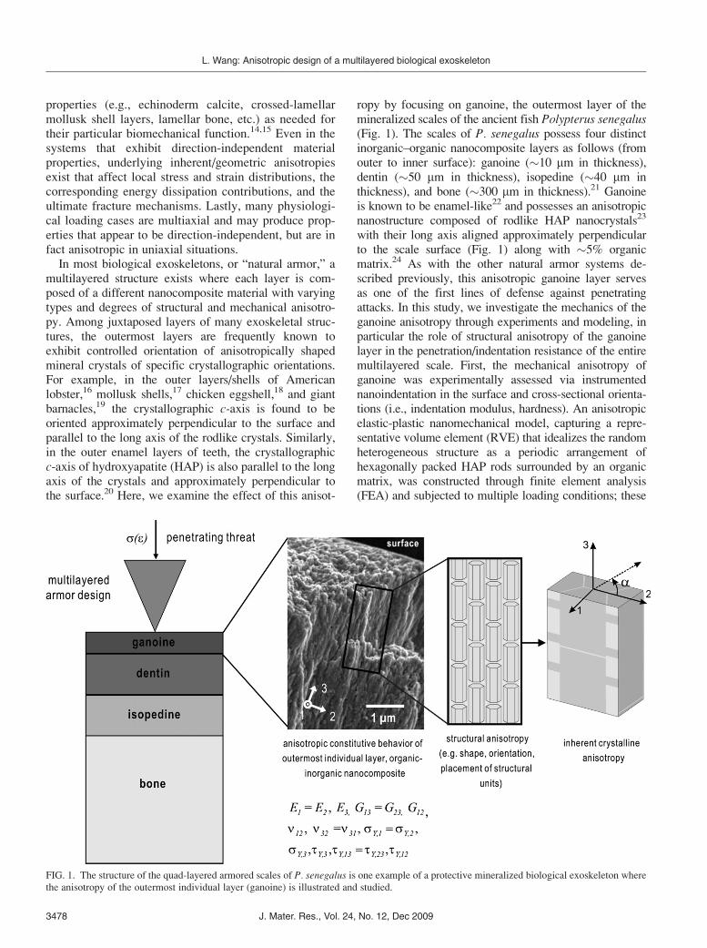
ropy by focusing on ganoine, the outermost layer of themineralized scales of the ancient fish Polypterus senegalus(Fig. 1). The scales of P. senegalus possess four distinctinorganic–organic nanocomposite layers as follows (fromouter to inner surface): ganoine (�10 mm in thickness),dentin (�50 mm in thickness), isopedine (�40 mm inthickness), and bone (�300 mm in thickness).21 Ganoineis known to be enamel-like22 and possesses an anisotropicnanostructure composed of rodlike HAP nanocrystals23
with their long axis aligned approximately perpendicularto the scale surface (Fig. 1) along with �5% organicmatrix.24 As with the other natural armor systems de-scribed previously, this anisotropic ganoine layer servesas one of the first lines of defense against penetratingattacks. In this study, we investigate the mechanics of theganoine anisotropy through experiments and modeling, inparticular the role of structural anisotropy of the ganoinelayer in the penetration/indentation resistance of the entiremultilayered scale. First, the mechanical anisotropy ofganoine was experimentally assessed via instrumentednanoindentation in the surface and cross-sectional orienta-tions (i.e., indentation modulus, hardness). An anisotropicelastic-plastic nanomechanical model, capturing a repre-sentative volume element (RVE) that idealizes the randomheterogeneous structure as a periodic arrangement ofhexagonally packed HAP rods surrounded by an organicmatrix, was constructed through finite element analysis(FEA) and subjected to multiple loading conditions; these
FIG. 1. The structure of the quad-layered armored scales of P. senegalus is one example of a protective mineralized biological exoskeleton where
the anisotropy of the outermost individual layer (ganoine) is illustrated and studied.
L. Wang: Anisotropic design of a multilayered biological exoskeleton
J. Mater. Res., Vol. 24, No. 12, Dec 20093478
nanomechanical models were then used to obtain the an-isotropic elasticity and plasticity of the ganoine layer andalso to reveal the contribution of the crystalline anisotropyof the HAP crystal (as opposed to geometric anisotropy) tothe overall anisotropy of the ganoine. The anisotropicnanomechanical modeling results were used in simulationof the nanoindentation of ganoine in orthogonal directionsand then compared with experimental nanoindentation da-ta. Furthermore, the anisotropic elastic-plastic behaviorwas captured in a continuum-level constitutive model toreveal the role of ganoine anisotropy in the entire multi-layered ganoine–dentin–isopedine–bone multilayered exo-skeleton structure, especially in terms of the penetrationresistance and deformation of the scale.
II. EXPERIMENTAL STUDY
A. Methods
1. Scale removal
A living Polypterus senegalus (length �20 cm) wasanesthetized, and a row of four scales surgically dissect-ed off from the 49th row on the left flank (posteriorregion). Tricaine methanesulfonate (MS-222, Sigma-Aldrich, St. Louis, MO) was used for general anesthesia,prepared at the concentration of 1.6 g/500 mL H2O with3 pellets of KOH for neutralization. The fish was subse-quently removed and immersed in a mixture of 50/50MS-222 and water from the tank to maintain anestheti-zation. Afterward, the fish was treated with tetracycline(250 mg; Thomas Laboratories, Tolleson, AZ).
2. Sample preparation
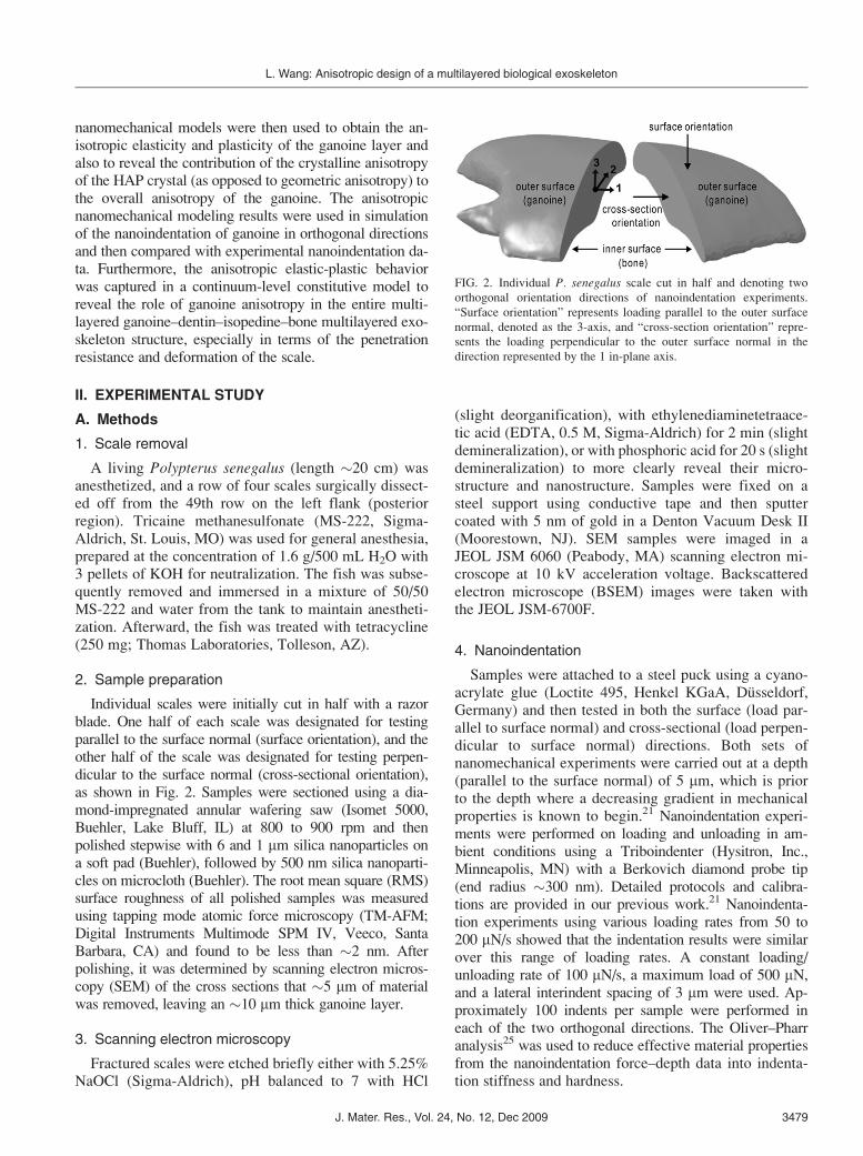
Individual scales were initially cut in half with a razorblade. One half of each scale was designated for testingparallel to the surface normal (surface orientation), and theother half of the scale was designated for testing perpen-dicular to the surface normal (cross-sectional orientation),as shown in Fig. 2. Samples were sectioned using a dia-mond-impregnated annular wafering saw (Isomet 5000,Buehler, Lake Bluff, IL) at 800 to 900 rpm and thenpolished stepwise with 6 and 1 mm silica nanoparticles ona soft pad (Buehler), followed by 500 nm silica nanoparti-cles on microcloth (Buehler). The root mean square (RMS)surface roughness of all polished samples was measuredusing tapping mode atomic force microscopy (TM-AFM;Digital Instruments Multimode SPM IV, Veeco, SantaBarbara, CA) and found to be less than �2 nm. Afterpolishing, it was determined by scanning electron micros-copy (SEM) of the cross sections that �5 mm of materialwas removed, leaving an �10 mm thick ganoine layer.
3. Scanning electron microscopy
Fractured scales were etched briefly either with 5.25%NaOCl (Sigma-Aldrich), pH balanced to 7 with HCl
(slight deorganification), with ethylenediaminetetraace-tic acid (EDTA, 0.5 M, Sigma-Aldrich) for 2 min (slightdemineralization), or with phosphoric acid for 20 s (slightdemineralization) to more clearly reveal their micro-structure and nanostructure. Samples were fixed on asteel support using conductive tape and then sputtercoated with 5 nm of gold in a Denton Vacuum Desk II(Moorestown, NJ). SEM samples were imaged in aJEOL JSM 6060 (Peabody, MA) scanning electron mi-croscope at 10 kV acceleration voltage. Backscatteredelectron microscope (BSEM) images were taken withthe JEOL JSM-6700F.
4. Nanoindentation
Samples were attached to a steel puck using a cyano-acrylate glue (Loctite 495, Henkel KGaA, Dusseldorf,Germany) and then tested in both the surface (load par-allel to surface normal) and cross-sectional (load perpen-dicular to surface normal) directions. Both sets ofnanomechanical experiments were carried out at a depth(parallel to the surface normal) of 5 mm, which is priorto the depth where a decreasing gradient in mechanicalproperties is known to begin.21 Nanoindentation experi-ments were performed on loading and unloading in am-bient conditions using a Triboindenter (Hysitron, Inc.,Minneapolis, MN) with a Berkovich diamond probe tip(end radius �300 nm). Detailed protocols and calibra-tions are provided in our previous work.21 Nanoindenta-tion experiments using various loading rates from 50 to200 mN/s showed that the indentation results were similarover this range of loading rates. A constant loading/unloading rate of 100 mN/s, a maximum load of 500 mN,and a lateral interindent spacing of 3 mm were used. Ap-proximately 100 indents per sample were performed ineach of the two orthogonal directions. The Oliver–Pharranalysis25 was used to reduce effective material propertiesfrom the nanoindentation force–depth data into indenta-tion stiffness and hardness.
FIG. 2. Individual P. senegalus scale cut in half and denoting two
orthogonal orientation directions of nanoindentation experiments.
“Surface orientation” represents loading parallel to the outer surface
normal, denoted as the 3-axis, and “cross-section orientation” repre-
sents the loading perpendicular to the outer surface normal in the
direction represented by the 1 in-plane axis.
L. Wang: Anisotropic design of a multilayered biological exoskeleton
J. Mater. Res., Vol. 24, No. 12, Dec 2009 3479
B. Results
1. Ultrastructure of ganoine
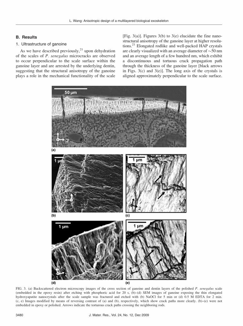
As we have described previously,21 upon dehydrationof the scales of P. senegalus microcracks are observedto occur perpendicular to the scale surface within theganoine layer and are arrested by the underlying dentin,suggesting that the structural anisotropy of the ganoineplays a role in the mechanical functionality of the scale
[Fig. 3(a)]. Figures 3(b) to 3(e) elucidate the fine nano-structural anisotropy of the ganoine layer at higher resolu-tions.21 Elongated rodlike and well-packed HAP crystalsare clearly visualized with an average diameter of�50 nmand an average length of a few hundred nm, which exhibita discontinuous and tortuous crack propagation paththrough the thickness of the ganoine layer [black arrowsin Figs. 3(c) and 3(e)]. The long axis of the crystals isaligned approximately perpendicular to the scale surface.
FIG. 3. (a) Backscattered electron microscopy images of the cross section of ganoine and dentin layers of the polished P. senegalus scale
(embedded in the epoxy resin) after etching with phosphoric acid for 20 s, (b)–(d) SEM images of ganoine exposing the thin elongated
hydroxyapatite nanocrystals after the scale sample was fractured and etched with (b) NaOCl for 5 min or (d) 0.5 M EDTA for 2 min.
(c, e) Images modified by means of reversing contrast of (a) and (b), respectively, which show crack paths more clearly. (b)–(e) were not
embedded in epoxy or polished. Arrows indicate the torturous crack paths crossing the neighboring rods.
L. Wang: Anisotropic design of a multilayered biological exoskeleton
J. Mater. Res., Vol. 24, No. 12, Dec 20093480
The ganoine nanostructure does exhibit some heterogene-ity in size distribution, as well as axial orientation angle,and the surfaces of the nanocrystals do not appear smoothbut corrugated.
2. Nanoindentation
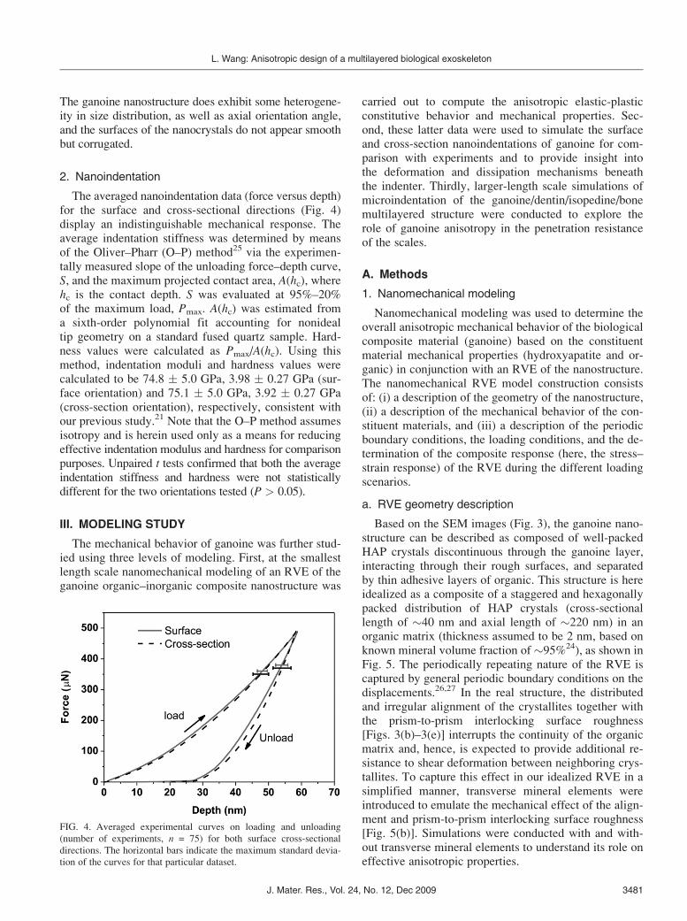
The averaged nanoindentation data (force versus depth)for the surface and cross-sectional directions (Fig. 4)display an indistinguishable mechanical response. Theaverage indentation stiffness was determined by meansof the Oliver–Pharr (O–P) method25 via the experimen-tally measured slope of the unloading force–depth curve,S, and the maximum projected contact area, A(hc), wherehc is the contact depth. S was evaluated at 95%–20%of the maximum load, Pmax. A(hc) was estimated froma sixth-order polynomial fit accounting for nonidealtip geometry on a standard fused quartz sample. Hard-ness values were calculated as Pmax/A(hc). Using thismethod, indentation moduli and hardness values werecalculated to be 74.8 � 5.0 GPa, 3.98 � 0.27 GPa (sur-face orientation) and 75.1 � 5.0 GPa, 3.92 � 0.27 GPa(cross-section orientation), respectively, consistent withour previous study.21 Note that the O–P method assumesisotropy and is herein used only as a means for reducingeffective indentation modulus and hardness for comparisonpurposes. Unpaired t tests confirmed that both the averageindentation stiffness and hardness were not statisticallydifferent for the two orientations tested (P > 0.05).
III. MODELING STUDY
The mechanical behavior of ganoine was further stud-ied using three levels of modeling. First, at the smallestlength scale nanomechanical modeling of an RVE of theganoine organic–inorganic composite nanostructure was
carried out to compute the anisotropic elastic-plasticconstitutive behavior and mechanical properties. Sec-ond, these latter data were used to simulate the surfaceand cross-section nanoindentations of ganoine for com-parison with experiments and to provide insight intothe deformation and dissipation mechanisms beneaththe indenter. Thirdly, larger-length scale simulations ofmicroindentation of the ganoine/dentin/isopedine/bonemultilayered structure were conducted to explore therole of ganoine anisotropy in the penetration resistanceof the scales.
A. Methods
1. Nanomechanical modeling
Nanomechanical modeling was used to determine theoverall anisotropic mechanical behavior of the biologicalcomposite material (ganoine) based on the constituentmaterial mechanical properties (hydroxyapatite and or-ganic) in conjunction with an RVE of the nanostructure.The nanomechanical RVE model construction consistsof: (i) a description of the geometry of the nanostructure,(ii) a description of the mechanical behavior of the con-stituent materials, and (iii) a description of the periodicboundary conditions, the loading conditions, and the de-termination of the composite response (here, the stress–strain response) of the RVE during the different loadingscenarios.
a. RVE geometry description
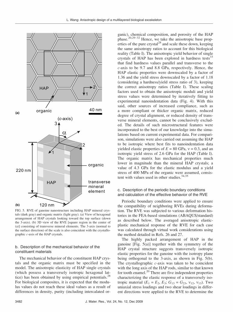
Based on the SEM images (Fig. 3), the ganoine nano-structure can be described as composed of well-packedHAP crystals discontinuous through the ganoine layer,interacting through their rough surfaces, and separatedby thin adhesive layers of organic. This structure is hereidealized as a composite of a staggered and hexagonallypacked distribution of HAP crystals (cross-sectionallength of �40 nm and axial length of �220 nm) in anorganic matrix (thickness assumed to be 2 nm, based onknown mineral volume fraction of �95%24), as shown inFig. 5. The periodically repeating nature of the RVE iscaptured by general periodic boundary conditions on thedisplacements.26,27 In the real structure, the distributedand irregular alignment of the crystallites together withthe prism-to-prism interlocking surface roughness[Figs. 3(b)–3(e)] interrupts the continuity of the organicmatrix and, hence, is expected to provide additional re-sistance to shear deformation between neighboring crys-tallites. To capture this effect in our idealized RVE in asimplified manner, transverse mineral elements wereintroduced to emulate the mechanical effect of the align-ment and prism-to-prism interlocking surface roughness[Fig. 5(b)]. Simulations were conducted with and with-out transverse mineral elements to understand its role oneffective anisotropic properties.
FIG. 4. Averaged experimental curves on loading and unloading
(number of experiments, n = 75) for both surface cross-sectional
directions. The horizontal bars indicate the maximum standard devia-
tion of the curves for that particular dataset.
L. Wang: Anisotropic design of a multilayered biological exoskeleton
J. Mater. Res., Vol. 24, No. 12, Dec 2009 3481
b. Description of the mechanical behavior of theconstituent materials
The mechanical behavior of the constituent HAP crys-tals and the organic matrix must be specified in themodel. The anisotropic elasticity of HAP single crystals(which possess a transversely isotropic hexagonal lat-tice) has been obtained by using empirical potentials.28
For biological composites, it is expected that the modu-lus values do not reach these ideal values as a result ofdifferences in density, purity (including intercalated or-
ganic), chemical composition, and porosity of the HAPphase.20,29–32 Hence, we take the anisotropic base prop-erties of the pure crystal28 and scale these down, keepingthe same anisotropy ratios to account for this biologicalreality (Table I). The anisotropic yield behavior of singlecrystals of HAP has been explored in hardness tests33
that find hardness values parallel and transverse to thec-axis to be 9.7 and 8.8 GPa, respectively. Hence, theHAP elastic properties were downscaled by a factor of1.36 and the yield stress downscaled by a factor of 1.18(considering a hardness/yield stress ratio of 3), keepingthe correct anisotropy ratios (Table I). These scalingfactors used to obtain the anisotropic moduli and yieldstress values were determined by iteratively fitting toexperimental nanoindentation data (Fig. 4). With thissaid, other sources of increased compliance, such asa more compliant or thicker organic matrix, reduceddegree of crystal alignment, or reduced density of trans-verse mineral elements, cannot be conclusively exclud-ed. The details of such microstructural features wereincorporated to the best of our knowledge into the simu-lations based on current experimental data. For compari-son, simulations were also carried out assuming the HAPto be isotropic where best fits to nanoindentation datayielded elastic properties of E = 80 GPa, n = 0.3, and anisotropic yield stress of 2.6 GPa for the HAP (Table I).The organic matrix has mechanical properties muchlower in magnitude than the mineral HAP crystals; avalue of 4.3 GPa for the elastic modulus and a yieldstress of 400 MPa of the organic were assumed, consis-tent with values used in other studies.34,35
c. Description of the periodic boundary conditionsand calculation of the effective behavior of the RVE
Periodic boundary conditions were applied to ensurethe compatibility of neighboring RVEs during deforma-tion. The RVE was subjected to various deformation his-tories in the FEA-based simulations (ABAQUS/standard)as described below. The averaged anisotropic elastic-plastic mechanical response of the RVE for each casewas calculated through virtual work considerations usingthe method detailed in Refs. 26 and 27.The highly packed arrangement of HAP in the
ganoine [Fig. 5(a)] together with the symmetry of theHAP crystal structure suggests transversely isotropicelastic properties for the ganoine with the isotropy planebeing orthogonal to the 3-axis, as shown in Fig. 5(b).The crystallographic c-axis was taken to be coincidentwith the long axis of the HAP rods, similar to that knownfor tooth enamel.20 There are five independent propertiescharacterizing the elastic response of a transversely iso-tropic material (E1 = E2, E3; G13 = G23, n12, n13). Twouniaxial stress loadings and two shear loadings in differ-ent directions were applied to the RVE to determine the
FIG. 5. RVE of ganoine nanostructure including HAP mineral crys-
tals (dark gray) and organic matrix (light gray). (a) View of hexagonal
arrangement of HAP crystals looking toward the top surface (down
the 3-axis). (b) 3D view of the RVE [square region in the center of
(a)] consisting of transverse mineral elements. The 3-axis (normal to
the surface direction) of the scale is also coincident with the crystallo-
graphic c-axis of the HAP crystals.
L. Wang: Anisotropic design of a multilayered biological exoskeleton
J. Mater. Res., Vol. 24, No. 12, Dec 20093482

effective composite anisotropic elastic constants andyield stresses. To investigate the elastic-plastic responseof the structure in different orientations, the RVE wasalso subjected to off-axis loadings. As shown in Fig. 5(b),uniaxial compression was applied to the RVE in direc-tions a = 0�, 15�, 30�, 45�, 60�, 75�, and 90� away fromthe rod axis.
2. Nanoindentation model
Nanoindentations into the surface and cross section ofganoine were simulated using three-dimensional nonlin-ear finite element analysis. The full nanoindentationprocess was modeled using one-quarter of the geometryof the system together with appropriate symmetryboundary conditions. The ganoine was discretized witheight-node linear hybrid brick elements (C3D8H inABAQUS/standard element library, Providence, RI).Mesh convergence was assessed, and a mesh of 16,704elements was found to provide an accurate solution[Fig. 6(a)]. The Berkovich indenter was modeled as arigid conical-like indenter; the tip cross-sectional areawas the experimentally measured Berkovich tip areafunction (TAF). The surface-to-surface contact betweenthe indenter surface and the ganoine surface was speci-fied to be frictionless with no overclosure.
The constitutive behavior of the ganoine was mod-eled in three ways: (i) isotropic elastic-perfectly plasticwith Young’s modulus E = 65 GPa, Poisson’s ratio n =0.3, yield stress sY = 1.53 GPa (data obtained fromfitting results to averaged nanoindentation dataFig. 4)21; (ii) anisotropic-elastic/anisotropic-plastic withthe properties obtained from the nanomechanical mod-eling (values to be reported in the Sec. III. B) and theanisotropic yield modeled using the Hill anisotropicyield condition; (iii) discrete modeling of the HAP rodsand organic matrix layers in the indentation regionincluding transverse mineral elements [Fig. 6(b)], toscale with the indenter geometry, and outer surroundingganoine regions following the corresponding continuumlevel anisotropic-elastic/anisotropic-plastic constitutiverepresentation.
In the FEA models, all of the nanoindentation simula-tions were conducted to a maximum load of 500 mN inaccord with the experiments; surface and cross-sectionalindents were simulated for all three cases of materialdescription described previously.
3. Microindentation model
Microindentation into the multilayered ganoine/den-tin/isopedine/bone scale was simulated using nonlinearFEA to/from indentation loads of 0.25 N, 0.50 N,0.75 N, and 1.0 N. Simulation details follow thosereported in our earlier work21 with the exception of theconstitutive modeling of the ganoine layer. The indenterfor the microindentation has a conical tip geometry thatemulates a Vickers microhardness tip with a radius of3.7 mm in accord with the microhardness experiments of
TABLE I. Mechanical properties of HAP crystals assumed in the nanomechanical model. The 3-axis was taken to be coincident with the
crystallographic c-axis.
E1 = E2
(GPa)
E3
(GPa)
G13
(GPa) n12 n13sY,1 = sY,2
(GPa)
sY,3
(GPa)
tY,13 = tY,23(GPa)
tY,12(GPa)
Isotropic 80 80 30.8 0.30 0.30 2.60 2.60 1.50 1.50
Anisotropic 86.4 73.6 24.5 0.23 0.29 2.47 2.73 1.50 1.43
FIG. 6. (a) 3D FEA nanoindentation model of nanoindentation of
outer ganoine layer showing finer mesh in region directly below the
indenter. (b) Discrete nanostructured model; more than 100 nanocrys-
tals surrounded by thin organic layers were incorporated within the
region directly below the indenter. The HAP minerals are meshed
with square cross sections.
L. Wang: Anisotropic design of a multilayered biological exoskeleton
J. Mater. Res., Vol. 24, No. 12, Dec 2009 3483
Ref. 21. The effective microhardness was computedfrom the FEA simulations in a manner consistent withthat used in the microhardness experiments, taking theindentation load and dividing it by the residual contactarea (i.e., the area corresponding to the radius of theresidual indent impression after unloading is complete).The role of ganoine anisotropy on the microlevel penetra-tion resistance of the multilayered scale was explored bycomparatively varying the ganoine constitutive behaviorin the FEA models. In the first model, presented in ourprevious work,21 the four material layers with thicknessescorresponding to their experimentally measured values(8, 46, 45, and 300 mm from outer to inner) were eachtaken to possess isotropic, elastic-perfectly plastic consti-tutive behavior; this multilayer model is referred to as theisotropic ganoine multilayer (IGML). The material con-stants have been reduced from nanoindentation data onthe individual layers and are provided in Table II. For thesecond model, the dentin, isopedine, and bone layer weretaken to be isotropic, and the ganoine is taken to beanisotropic; this model is referred to as the anisotropicganoine multilayer (AGML). In this model, the ganoinelayer was represented by a continuum level constitutivemodel of the anisotropic-elastic/anisotropic-plastic behav-ior used also in the nanoindentation simulations describepreviously with the properties reduced from the nanome-chanical modeling simulations (described in Sec. III. B);the anisotropic plasticity was captured using the Hill an-isotropic yield condition. In order to compare both multi-layer models, simulations of indentation into a monolithicisotropic ganoine (to be referred to as MIG) material wereconducted.
B. Results
1. Nanomechanical modeling
Figures 7(a) and 7(b) depict the ganoine stress–strainresponses computed from the ganoine nanomechanicalmodel simulations for the RVE, which considers theHAP rods to be inherently isotropic and the matrix con-tinuity to be interrupted by transverse mineral elements[henceforth referred to as RVE (A)]. Results consideringuniaxial compressions in directions aligned with, 45�off-axis from, and transverse to the long axis of theHAP rods as well as shear in the planes with normals
defined by n = e3, n = 0.707 e1 + 0.707 e3, and n = e1.The axial modulus and yield strength in the directionaligned with the prism axis are 15% and 26% larger thanthe transverse values. The off-axis axial response has thelowest modulus and strength since it samples the shear-ing of the matrix. The shear modulus and yield strengthin the transverse plane are 13% and 100% larger than theout-of-plane values, respectively; the off-axis shear hasthe greatest shear modulus and shear strength as a resultof the unfavorable orientation of the organic layers dur-ing this shear loading. Table III provides the full set ofanisotropic material constants for the ganoine layer de-termined from the complete simulated response (includ-ing lateral contractions during uniaxial stress conditions)of the simulation. A second set of material propertieswas also deduced for the case where the HAP crystalresponse was taken to be anisotropic with the crystalproperties previously listed in Table I.The directional dependence of the Young’s modulus
and axial yield stress were computed from simulations ofuniaxial loading in different directions and are shown inFigs. 7(c) and 7(d), respectively. Results for RVE (A)are compared with two other RVEs: RVE (B), whichconsiders isotropic HAP crystals but lacks transversemineral elements, and RVE (C), which considers aniso-tropic HAP crystals and includes transverse mineral ele-ments. Values for off-axis axial modulus were alsocomputed by transformation of the computed anisotropicstiffness tensor of each RVE case, giving the continuouscurves of Fig. 7(c), which are fully consistent with thevalues computed via off-axis simulations. Examining theresults of RVE (A), the transverse modulus and yieldstress (�90�) are observed to be lower than the axialaxis values (�0�, by 13% and 21%, respectively); thelowest values occur off-axis (�45�) because of the ex-tensive shearing of the matrix. Comparing RVE (A) toRVE (B), we find the presence of transverse mineralelements to provide a modest increase in the modulus[Fig. 7(c)] in all directions as expected; the transversemineral elements have a dramatic effect on off-axis yield(up to four times smaller) since the absence of transverseminerals enables easy shear yielding of the matrix whenloading off-axis [Fig. 7(d)]. Interestingly, a “doubleyield” is observed for RVE (B) when loading at a = 75�[Fig. 7(b)] where the first yield occurs at a low stressbecause of matrix shear. However, as deformation pro-gresses, the HAP rods rotate (unhindered by the lack oftransverse mineral elements), and the axial stress neededto provide a resolved shear stress that would yield thematrix layer monotonically increases until reaching apoint where yielding of the HAP is reached. This can beinterpreted as a geometrically induced self-hardeningmechanism. Comparing results of RVE (A) to RVE (C)reveals the influence of the HAP crystal anisotropy onthe anisotropic response of the ganoine. The modest
TABLE II. Isotropic material properties used in FEA model of
microindentation into multilayered P. senegalus scale,21 obtained
from isotropic elastic-plastic FEA fits to nanoindentation data for
each layer.
Thickness (mm) Modulus (GPa) Yield strength (GPa)
Ganoine 8 65 1.53
Dentin 46 25 0.40
Isopedine 45 14.5 0.215
Bone 300 13.5 0.18
L. Wang: Anisotropic design of a multilayered biological exoskeleton
J. Mater. Res., Vol. 24, No. 12, Dec 20093484
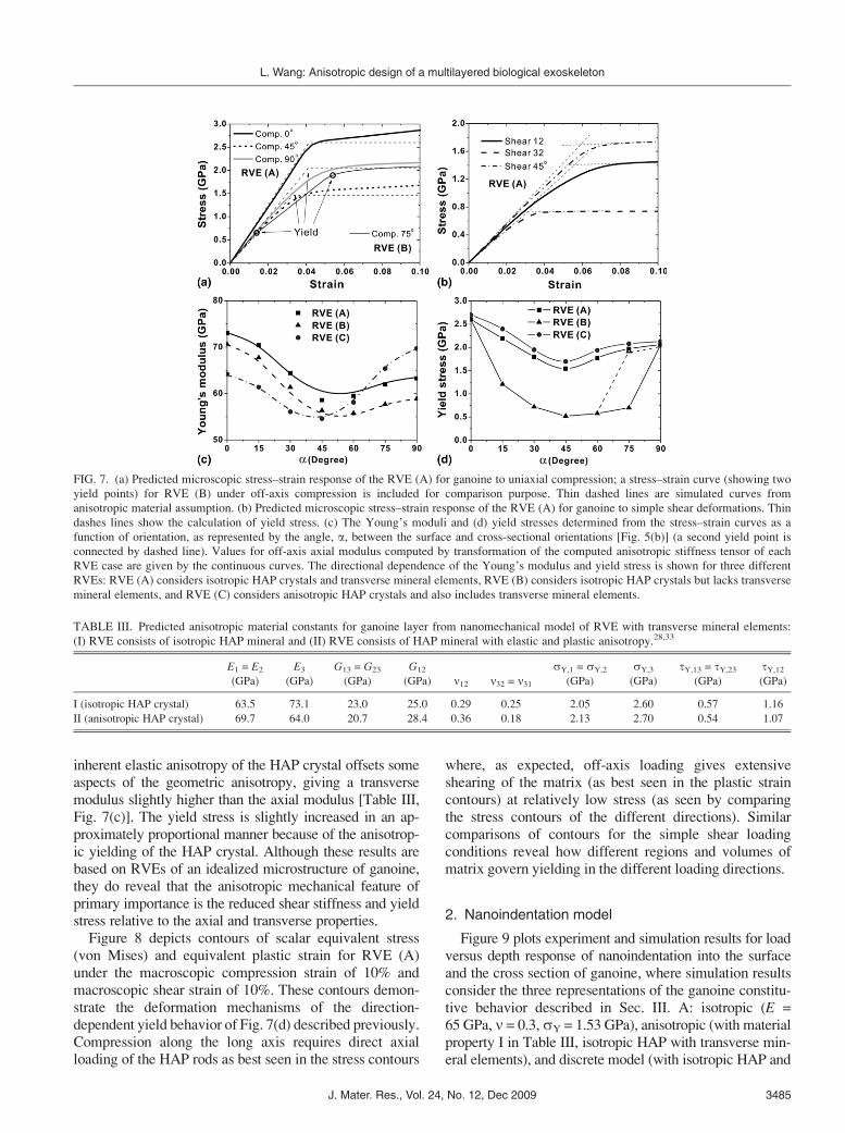
inherent elastic anisotropy of the HAP crystal offsets someaspects of the geometric anisotropy, giving a transversemodulus slightly higher than the axial modulus [Table III,Fig. 7(c)]. The yield stress is slightly increased in an ap-proximately proportional manner because of the anisotrop-ic yielding of the HAP crystal. Although these results arebased on RVEs of an idealized microstructure of ganoine,they do reveal that the anisotropic mechanical feature ofprimary importance is the reduced shear stiffness and yieldstress relative to the axial and transverse properties.
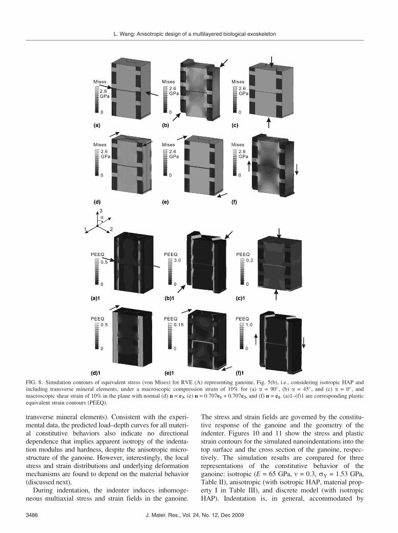
Figure 8 depicts contours of scalar equivalent stress(von Mises) and equivalent plastic strain for RVE (A)under the macroscopic compression strain of 10% andmacroscopic shear strain of 10%. These contours demon-strate the deformation mechanisms of the direction-dependent yield behavior of Fig. 7(d) described previously.Compression along the long axis requires direct axialloading of the HAP rods as best seen in the stress contours
where, as expected, off-axis loading gives extensiveshearing of the matrix (as best seen in the plastic straincontours) at relatively low stress (as seen by comparingthe stress contours of the different directions). Similarcomparisons of contours for the simple shear loadingconditions reveal how different regions and volumes ofmatrix govern yielding in the different loading directions.
2. Nanoindentation model
Figure 9 plots experiment and simulation results for loadversus depth response of nanoindentation into the surfaceand the cross section of ganoine, where simulation resultsconsider the three representations of the ganoine constitu-tive behavior described in Sec. III. A: isotropic (E =65 GPa, n = 0.3, sY = 1.53 GPa), anisotropic (with materialproperty I in Table III, isotropic HAP with transverse min-eral elements), and discrete model (with isotropic HAP and
FIG. 7. (a) Predicted microscopic stress–strain response of the RVE (A) for ganoine to uniaxial compression; a stress–strain curve (showing two
yield points) for RVE (B) under off-axis compression is included for comparison purpose. Thin dashed lines are simulated curves from
anisotropic material assumption. (b) Predicted microscopic stress–strain response of the RVE (A) for ganoine to simple shear deformations. Thin
dashes lines show the calculation of yield stress. (c) The Young’s moduli and (d) yield stresses determined from the stress–strain curves as a
function of orientation, as represented by the angle, a, between the surface and cross-sectional orientations [Fig. 5(b)] (a second yield point is
connected by dashed line). Values for off-axis axial modulus computed by transformation of the computed anisotropic stiffness tensor of each
RVE case are given by the continuous curves. The directional dependence of the Young’s modulus and yield stress is shown for three different
RVEs: RVE (A) considers isotropic HAP crystals and transverse mineral elements, RVE (B) considers isotropic HAP crystals but lacks transverse
mineral elements, and RVE (C) considers anisotropic HAP crystals and also includes transverse mineral elements.
TABLE III. Predicted anisotropic material constants for ganoine layer from nanomechanical model of RVE with transverse mineral elements:
(I) RVE consists of isotropic HAP mineral and (II) RVE consists of HAP mineral with elastic and plastic anisotropy.28,33
E1 = E2
(GPa)
E3
(GPa)
G13 = G23
(GPa)
G12
(GPa) n12 n32 = n31sY,1 = sY,2
(GPa)
sY,3
(GPa)
tY,13 = tY,23(GPa)
tY,12(GPa)
I (isotropic HAP crystal) 63.5 73.1 23.0 25.0 0.29 0.25 2.05 2.60 0.57 1.16
II (anisotropic HAP crystal) 69.7 64.0 20.7 28.4 0.36 0.18 2.13 2.70 0.54 1.07
L. Wang: Anisotropic design of a multilayered biological exoskeleton
J. Mater. Res., Vol. 24, No. 12, Dec 2009 3485
transverse mineral elements). Consistent with the experi-mental data, the predicted load–depth curves for all materi-al constitutive behaviors also indicate no directionaldependence that implies apparent isotropy of the indenta-tion modulus and hardness, despite the anisotropic micro-structure of the ganoine. However, interestingly, the localstress and strain distributions and underlying deformationmechanisms are found to depend on the material behavior(discussed next).
During indentation, the indenter induces inhomoge-neous multiaxial stress and strain fields in the ganoine.
The stress and strain fields are governed by the constitu-tive response of the ganoine and the geometry of theindenter. Figures 10 and 11 show the stress and plasticstrain contours for the simulated nanoindentations into thetop surface and the cross section of the ganoine, respec-tively. The simulation results are compared for threerepresentations of the constitutive behavior of theganoine: isotropic (E = 65 GPa, n = 0.3, sY = 1.53 GPa,Table II), anisotropic (with isotropic HAP, material prop-erty I in Table III), and discrete model (with isotropicHAP). Indentation is, in general, accommodated by
FIG. 8. Simulation contours of equivalent stress (von Mises) for RVE (A) representing ganoine, Fig. 5(b), i.e., considering isotropic HAP and
including transverse mineral elements, under a macroscopic compression strain of 10% for (a) a = 90�, (b) a = 45�, and (c) a = 0�, andmacroscopic shear strain of 10% in the plane with normal (d) n = e3, (e) n = 0.707e1 + 0.707e3, and (f) n = e1. (a)1–(f)1 are corresponding plastic
equivalent strain contours (PEEQ).
L. Wang: Anisotropic design of a multilayered biological exoskeleton
J. Mater. Res., Vol. 24, No. 12, Dec 20093486

compressing material beneath the indenter and shearingmaterial away from under the indenter. Comparing theanisotropic ganoine case to the isotropic case, the com-pressive normal stress (S33) is seen to occur in a narrowerband and to extend to deeper depths for the anisotropiccases (Fig. 10) as a consequence of the more diffuseplastic shear straining (PE13) that occurs at lower shearstress (S13) for the anisotropic case (a direct consequenceof the reduced shear yield stress). This has consequencesin how load and deformation are transmitted to the under-lying dentin layer during microindentation of the multi-layered scale (see Sec. IV). Comparison of the continuumconstitutive behavior of ganoine to the discrete structuralrepresentation of ganoine reveals the role of the rodlikenanostructure during nanoindentation. Large bands of in-tense plastic deformation are observed in the organic ma-trix layers, and yielding of the HAP rods and transversemineral elements also takes place and contributes to thetotal energy dissipation density (see the shear contours ofFigs. 10 and 11). While the discrete model captures theseparate contributions of the HAP prisms and the organiclayers, comparison of the discrete model results to the
FIG. 10. Simulation contours of stress distributions, plastic strain, and energy dissipation of the ganoine layer under nanoindentation with the
loading parallel to the surface normal (3-axis). A comparison is shown between isotropic (Table II, row 1), anisotropic (isotropic HAP crystals)
(Table III, row I), and transverse mineral elements [RVE (A)], [Fig. 5(b)], and discrete models for 3D nanoindentation [Fig. 6(b)].
FIG. 9. Comparison of the average experimental curves to the FEA
simulation curves obtained by virtual nanoindentation after the full
anisotropic material set for ganoine was determined using the proper
nanomechanical models. (i) Isotropic properties with E = 65 GPa, n =
0.3, and sY = 1.53 GPa (Table II, row 1). (ii) Anisotropic properties
using data obtained from the nanomechanical modeling with isotropic
HAP crystals (Table III, row I) and transverse mineral elements [RVE
(A)]. (iii) Discrete model assuming isotropic HAP rods [Fig. 6(b)].
L. Wang: Anisotropic design of a multilayered biological exoskeleton
J. Mater. Res., Vol. 24, No. 12, Dec 2009 3487
continuum anisotropic model results shows very similaroverall contours even for this nanoindentation where thelength scale of the rod width is of order of the depth of theindentation; hence, these results also show that use of thecontinuum level anisotropic model will be sufficient tocapture the anisotropic behavior of the ganoine during thelarger length scale microindentation simulations. It shouldbe noted that anisotropy of HAP does not affect the stress/strain distributions in these nanoindentation models be-cause yield stresses dominate stress and strain fields.Table IV compares O–P modulus and O–P hardnessvalues obtained from experimental measurements and
from the simulations assuming the different material mod-els including isotropic model, anisotropic model (withmaterial properties I or HAP isotropic and II or HAPanisotropic, Table III), and discrete model. The modulusand hardness were reduced from the load–depth curvesusing the Oliver–Pharr method (which assumes the mate-rial to be homogeneous and isotropic).
3. Microindentation model
The role of ganoine anisotropy in the larger length-scale biomechanical microindentation of the multilayered
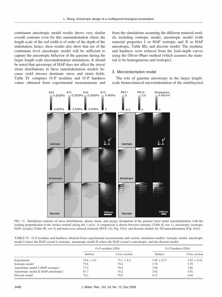
FIG. 11. Simulation contours of stress distributions, plastic strain, and energy dissipation of the ganoine layer under nanoindentation with the
loading perpendicular to the surface normal (along the 1-axis). A comparison is shown between isotropic (Table II, row 1), anisotropic (isotropic
HAP crystals) (Table III, row I) and transverse mineral elements [RVE (A), Fig. 5(b)], and discrete models for 3D nanoindentation [Fig. 6(b)].
TABLE IV. O–P modulus and hardness obtained from experimental measurements and various simulation models: isotropic model, anisotropic
model I where the HAP crystal is isotropic, anisotropic model II where the HAP crystal is anisotropic, and the discrete model.
O–P modulus (GPa) O–P hardness (GPa)
Surface Cross section Surface Cross section
Experiments 74.8 � 5.0 75.1 � 8.2 3.98 � 0.27 3.92 � 0.34
Isotropic model 75.6 75.6 3.70 3.70
Anisotropic model I (HAP isotropic) 77.2 70.8 3.86 3.86
Anisotropic model II (HAP anisotropic) 67.7 74.2 3.82 3.92
Discrete model 74.2 70.9 4.12 4.04
L. Wang: Anisotropic design of a multilayered biological exoskeleton
J. Mater. Res., Vol. 24, No. 12, Dec 20093488

P. senegalus scale was explored by constructing twoFEA models, the isotropic ganoine multilayer (IGML)(reported previously21) and the anisotropic ganoine multi-layer (AGML) described in Sec. III. A. 3. We recall that,despite the clearly anisotropic microstructure of theganoine layer, the experimental and predicted force–depthbehavior and effective indentation modulus and indenta-tion hardness were found to be independent of directionand to also be independent of constitutive representation(i.e., whether ganoine was modeled as isotropic, aniso-tropic, or discrete). However, the underlying deformationmechanisms, revealed in the simulations, had subtledependencies on anisotropy. Here, the effect of ganoineanisotropy on the effective microindentation behavior ofthe multilayered structure is explored—examining the ef-fect of both the effective force–depth behavior and theunderlying deformation and dissipation mechanisms.
Figure 12(a) depicts the load–depth curves of theIGML and AGML multilayered structures to/from maxi-mum loads of 0.5 and 1 N, compared with a simulationof monolithic isotropic ganoine (MIG). As also previ-ously found in the ganoine nanoindentation cases, theIGML and AGML load–depth behaviors and corre-sponding reduced material properties were found to benearly identical, giving effective modulus (�30 GPa),
effective microhardness (�1.7 to 1.8 GPa), and energydissipation (1.6 to �1.65 mJ). Indentation to/from differ-ent maximum load levels reveals the effective micro-hardness for both models to decrease nonlinearly withincreasing indentation load [Fig. 12(b)]. The predictedmicrohardness values show good agreement with theexperimentally measured Vickers microhardness[Fig. 12(b)]. In the 0.25 and 0.5 N microindentationexperiments, most samples (�9 of 10 indents) were ob-served to deform in an elastic-plastic manner with nosurface cracks observed.21 In the 1 N cases, �50% ofthe samples (�5 of 10 indents) showed circumferentialsurface cracking. Circumferential cracks were observedin all of the 2 N cases (10 of 10 indents).21
The predicted effective total energy dissipation [areabetween the loading and unloading force–depth curves,e.g., Fig. 12(a)] as a function of maximum indentationload for the IGML and AGML microlayered modelswere found to be indistinguishable, increasing nonli-nearly from close to that of the MIG model at smallmaximum loads to values nearly double the dissipationenergy of the MIG at a maximum load of 1 N [Fig. 12(c)].The evolution of the work of indentation during loadingand unloading of the entire multilayered structure, as wellas the individual contributions of the ganoine and the dentin
FIG. 12. Predictions of effective microindentation mechanical properties of the multilayered P. senegalus scale; notations include monolithic
isotropic ganoine (MIG), isotropic ganoine multilayer (IGML), and anisotropic ganoine multilayer (AGML), respectively. (a) Simulated micro-
indentation load-versus-depth curves. (b) Simulated effective microhardness compared to experimentally measured values as a function of
maximum indentation load, reported by us previously.21 OM and AFM indicate optical microscope and atomic force microscope, respectively,
which were used to measure the residual area after unloading. (c) Simulated effective energy dissipation as a function of maximum indentation
load. Dissipation energy was calculated as the area between the loading and unloading portion of the load–depth curves in microindentation after
unloading. (d) Simulated energy evolution (the work of indentation) of the whole multilayered structure [IGML (black lines) and AGML (gray
lines)], and the individual ganoine and dentin layers as a function of applied load up to a 1 N maximum load, as well as on unloading.
L. Wang: Anisotropic design of a multilayered biological exoskeleton
J. Mater. Res., Vol. 24, No. 12, Dec 2009 3489
layers is provided in Fig. 12(d). For both the IGML andAGML systems, a nonlinear increase in the work of in-dentation is observed during loading followed by theelastic recovery during unloading. Although both theIGML and AGML microlayered models exhibit a similartotal energy evolution during loading and unloading, lo-cally the ganoine and dentin layers in the IGML and theAGML structures contribute differently to the total ener-gy evolution. During the early loading stage (<0.25 N),the ganoine and dentin layers of AGML case partitionenergy in a manner similar to that found in the IGMLcase. However, as the load is further increased, the ener-gy-dissipation contribution of the dentin in the AGMLcase begins to increase more significantly than in theIGML case (because of dentin yielding earlier and,hence, greater plastic dissipation in dentin in the AGMLcase). At a maximum load of 1 N, the contributions to thework of indentation from ganoine and from dentin differfor the IGML and AGML models; with dentin in the
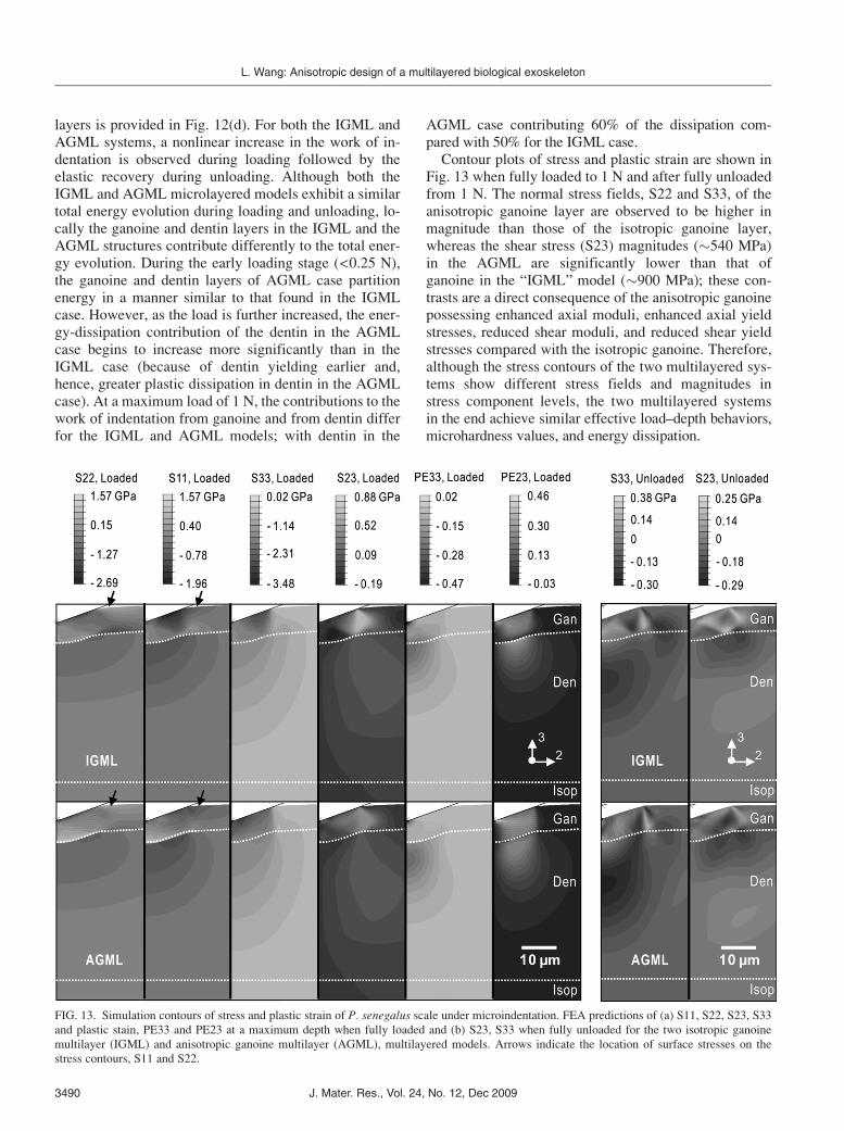
AGML case contributing 60% of the dissipation com-pared with 50% for the IGML case.Contour plots of stress and plastic strain are shown in
Fig. 13 when fully loaded to 1 N and after fully unloadedfrom 1 N. The normal stress fields, S22 and S33, of theanisotropic ganoine layer are observed to be higher inmagnitude than those of the isotropic ganoine layer,whereas the shear stress (S23) magnitudes (�540 MPa)in the AGML are significantly lower than that ofganoine in the “IGML” model (�900 MPa); these con-trasts are a direct consequence of the anisotropic ganoinepossessing enhanced axial moduli, enhanced axial yieldstresses, reduced shear moduli, and reduced shear yieldstresses compared with the isotropic ganoine. Therefore,although the stress contours of the two multilayered sys-tems show different stress fields and magnitudes instress component levels, the two multilayered systemsin the end achieve similar effective load–depth behaviors,microhardness values, and energy dissipation.
FIG. 13. Simulation contours of stress and plastic strain of P. senegalus scale under microindentation. FEA predictions of (a) S11, S22, S23, S33
and plastic stain, PE33 and PE23 at a maximum depth when fully loaded and (b) S23, S33 when fully unloaded for the two isotropic ganoine
multilayer (IGML) and anisotropic ganoine multilayer (AGML), multilayered models. Arrows indicate the location of surface stresses on the
stress contours, S11 and S22.
L. Wang: Anisotropic design of a multilayered biological exoskeleton
J. Mater. Res., Vol. 24, No. 12, Dec 20093490
In our previous study,21 the 1 N maximum load experi-ments and simulations were used to estimate a maximumnormal stress brittle-failure condition for the ganoine:experimentally, circumferential cracks were observed onthe surface during microhardness experiments at 1 Nmaximum load. Using contours of the radial stress, S22,at this maximum load level gave a critical normal stressof �1.1 GPa from results of our “IGML” model. Here,contours of S22 from both the “IGML” and the “AGML”multilayer models compute similar magnitudes in tensileS22 surface values whereas their circumferential stressfields (S33) exhibit compressive values at the surface,again suggesting that circumferential cracking on the sur-face is the preferred failure mode in these multilayeredsystems. These results also indicate that the anisotropy isnot the primary structural property governing this aspectof the surface stress distribution, but instead it is thecontrast in the ganoine and dentin behavior that gives thismechanical behavior. However, after circumferentialcracking is initiated, the anisotropic rodlike structure willfacilitate the propagation vertically, which is more advan-tageous since it can be arrested by the energy dissipatingdentin layer, rather than propagating in other directions(e.g., radially), which could lead to catastrophic structuralfailure. Additionally, the interfacial normal and shearstresses are known to be important factors in the interfa-cial failure in other multilayer systems.21,36 The interfa-cial (and close to interface) shear stresses in the AGMLcase (S23) are found to be significantly lower duringloading than those in the IGML case, a consequence ofthe lower shear yield stress (ty23). Upon unloading, apeak shear stress is present on the interface of both casesbut is lower in the AGML case. The lower shear yieldstress (ty23) of the anisotropic ganoine is seen to favorplastic deformation via plastic shear straining (comparingPE23 contours) and thus to also promote a radial spread-ing of plastic deformation in the ganoine layer (PE23contours) compared with more direct compression strain-ing (comparing PE33 contours). The different plasticstraining of the ganoine layer in the two cases is observedto result in different curvatures of the ganoine/dentin in-terface. The plasticity in the underlying dentin layer isspatially more elongated in depth for the anisotropicganoine compared to the isotropic case (PE23, PE33).
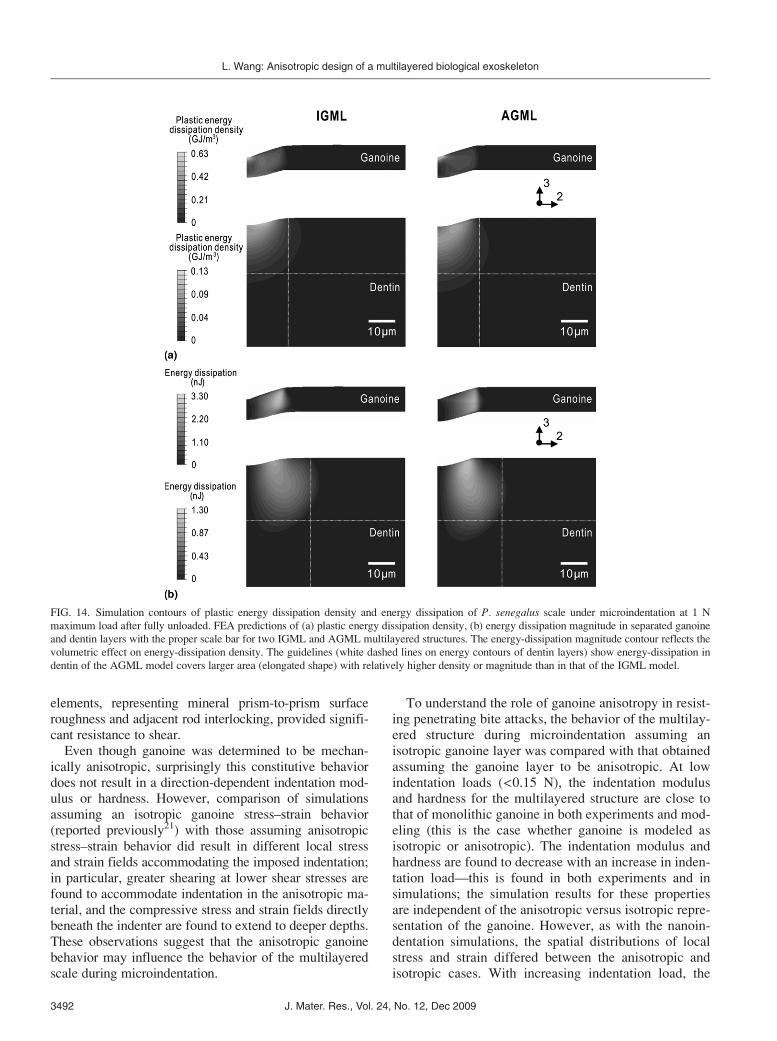
Contours of plastic energy dissipation density (energydissipation per unit volume) and energy dissipation mag-nitude (dissipation energy accounting for the volumeover which the dissipation occurs—although this is amesh-dependent quantity, it provides a useful compari-son between cases when the same mesh is used) for eachlayer when fully unloaded are depicted in Fig. 14. Thecontours of each layer are scaled differently to betterreveal the contributions of each layer. Plastic energydissipation density contours in Fig. 14(a) show the over-all plastic deformation reveals less plasticity in the
ganoine layer accompanied by greater dissipation in thedentin layer for the AGML case. In the energy dissipationmagnitude contours [Fig. 14(b)], taking into account thevolume over which the energy dissipation occurs enablesassessment of where energy dissipation is dominant with-in a layer as well as comparison between cases. In partic-ular, the dissipation magnitude contours capture theincreased volume of points as one moves radially outwardaway from the axis of indentation, revealing the dominantdissipation role around the perimeter of indentation; thesecontours also reveal the more prevalent dissipation role ofdentin in the AGML and of ganoine in the IGML. Bothforms of energy contours reflect greater energy dissipa-tion in dentin in the AGML (Fig. 12).
IV. DISCUSSION
A major threat to P. senegalus is biting from its ownspecies, which takes place during territorial fighting andfeeding.37 The tooth geometry and size make these pene-tration biting events approximately analogous to microin-dentation. In our previous work,21 we demonstrated thatthe micrometer-scale multilayered structure acts to pro-vide an initially stiff and hard line of defense against low-load events, governed by the behavior of the outer ganoinelayer. This behavior transitions to an increasingly dissipa-tive response with increasing penetration load where theunderlying dentin layer provides the dissipation. The goalof this study was to investigate the role of the anisotropy ofthe prismaticlike ganoine structure in the load-dependentpenetration resistance of the entire multilayered armor.The design principles identified are expected to be rele-vant to a broad array of biological exoskeletons, sincemany different species exhibit similar nanostructures intheir outermost layers,16–19 and to the development ofimproved biologically-inspired structural materials.
Nanomechanical modeling results revealed that theunique structure of ganoine does indeed result in elastic-plastic mechanical anisotropy (transverse isotropy) of thecomposite material. The balance between smaller lengthscale “inherent” anisotropy of the crystalline HAP andlarger length scale “geometric” anisotropy of the HAP-organic composite nanostructure was explored, a topicrelevant for most biological composites. Since the HAPcrystal is modestly anisotropic, it has a minimal effect onthe anisotropic elastic-plastic response of the ganoinecomposite, which is rather dominated by geometric an-isotropy of the composite nanostructure. This minimaleffect of HAP anisotropy has also been reported on theother composite systems (e.g., bone1). Enhanced axial andtransverse moduli (and yield stresses) and significantlyreduced shear moduli (and yield stresses) were predicted.The shear moduli also correlate with reduced off-axisaxial moduli and yield stresses, which result from sheardeformation of the organic interlayers. Transverse mineral
L. Wang: Anisotropic design of a multilayered biological exoskeleton
J. Mater. Res., Vol. 24, No. 12, Dec 2009 3491
elements, representing mineral prism-to-prism surfaceroughness and adjacent rod interlocking, provided signifi-cant resistance to shear.
Even though ganoine was determined to be mechan-ically anisotropic, surprisingly this constitutive behaviordoes not result in a direction-dependent indentation mod-ulus or hardness. However, comparison of simulationsassuming an isotropic ganoine stress–strain behavior(reported previously21) with those assuming anisotropicstress–strain behavior did result in different local stressand strain fields accommodating the imposed indentation;in particular, greater shearing at lower shear stresses arefound to accommodate indentation in the anisotropic ma-terial, and the compressive stress and strain fields directlybeneath the indenter are found to extend to deeper depths.These observations suggest that the anisotropic ganoinebehavior may influence the behavior of the multilayeredscale during microindentation.
To understand the role of ganoine anisotropy in resist-ing penetrating bite attacks, the behavior of the multilay-ered structure during microindentation assuming anisotropic ganoine layer was compared with that obtainedassuming the ganoine layer to be anisotropic. At lowindentation loads (<0.15 N), the indentation modulusand hardness for the multilayered structure are close tothat of monolithic ganoine in both experiments and mod-eling (this is the case whether ganoine is modeled asisotropic or anisotropic). The indentation modulus andhardness are found to decrease with an increase in inden-tation load—this is found in both experiments and insimulations; the simulation results for these propertiesare independent of the anisotropic versus isotropic repre-sentation of the ganoine. However, as with the nanoin-dentation simulations, the spatial distributions of localstress and strain differed between the anisotropic andisotropic cases. With increasing indentation load, the
FIG. 14. Simulation contours of plastic energy dissipation density and energy dissipation of P. senegalus scale under microindentation at 1 N
maximum load after fully unloaded. FEA predictions of (a) plastic energy dissipation density, (b) energy dissipation magnitude in separated ganoine
and dentin layers with the proper scale bar for two IGML and AGML multilayered structures. The energy-dissipation magnitude contour reflects the
volumetric effect on energy-dissipation density. The guidelines (white dashed lines on energy contours of dentin layers) show energy-dissipation in
dentin of the AGML model covers larger area (elongated shape) with relatively higher density or magnitude than in that of the IGML model.
L. Wang: Anisotropic design of a multilayered biological exoskeleton
J. Mater. Res., Vol. 24, No. 12, Dec 20093492
anisotropic stiffness and yield strength of the ganoinewere found to promote a greater level of plastic defor-mation in the dentin in radial and depth directions. Thisincreasing volume of plastic deformation in the underly-ing dentin layer promotes the use of the dentin layer asthe major dissipation element in the multilayered struc-ture, in essence “protecting” the outer ganoine layer bylimiting the strain and stress that the ganoine will expe-rience. The anisotropic constitutive behavior of theganoine also spreads the plastic deformation and energydissipation to a greater volume of material overall.
Both the isotropic and anisotropic treatments of theganoine stress–strain behavior are found to result in ten-sile radial stress field (S22) and compressive circumfer-ential stress field (S11) on the surface around theindentation perimeter; the tensile radial stress promotescircumferential cracking whereas the compressive cir-cumferential stress suppresses radial cracking. Circum-ferential cracking would be a favored failure event sinceit would be localized to the indentation region and wouldnot be a propagating failure across the scale. Moreover,the discrete prism structure does provide the fracturepathway (normal to the scale surface between HAP rods)after initiation of circumferential cracks. Such failurepathways lead to the localized damage in the ganoineand then are easily arrested by the ductile dentin layer.These different findings of the underlying deformation,stress, and dissipation behavior when the outer layer isslightly anisotropic rather than isotropic motivates amore thorough parametric investigation into the poten-tial of using and designing anisotropic outer (and inner)layers to promote dissipation during penetration events.
Our results on ganoine are expected to be relevant aswell for human teeth. Human teeth are composed of anouter enamel layer that has a composite HAP-organicstructure of similar composition to ganoine also fol-lowed by an underlying dentin layer. However, thereare a number of notable differences between these twosystems: (1) the ganoine thickness is �10 mm in contrastto tooth enamel which has thickness > mm presumablydue to the larger length scale of the mastication processand (2) tooth enamel has an additional higher order levelof anisotropic structural geometric hierarchy wherebythe HAP nanocrystals self-assemble into micrometer-scale “rods” with their long axes perpendicular to thetooth surface (absent in ganoine). The anisotropic elasticand plastic properties reported in this study for ganoineare consistent with those previously reported for intrarodtooth enamel.38 Larger length scale mechanical experi-ments involving multiple rods revealed amplified mechan-ical anisotropy compared with the constituent enamelcomposite, elucidating the effect of the second level ofstructural hierarchy.34,38 A FEA study considered differentanisotropy ratios for enamel and demonstrated that an in-creasing anisotropic nature would more directly transfer
stresses to underlying compliant dentine and thus reducethe potential for tooth fracture,39 a result consistent withthose we obtain for ganoine here. Lastly, similar toganoine, this anisotropic structure is assumed to be benefi-cial in directing cracks vertically down into the dentin.40
Our study emphasizes the critical importance of theanisotropy of structural biological material at the nano-scale and the microscale in achieving macroscale me-chanical properties to optimize penetration resistance andprotection. The fundamental understanding of this optimi-zation in a multilayered natural armor structure suggestsan anisotropic design to improve biomimetic systems.
ACKNOWLEDGMENTS
The authors would like to acknowledge use of theMIT Department of Materials Science and EngineeringNanomechanical Testing Facility for the experimentsconducted there. Thank you to A. Schwartzman for histraining and assistance with the experiments. We alsogratefully acknowledge the support of the National Sci-ence Foundation MIT Center for Materials Science andEngineering (DMR-0819762), the US Army through theMIT Institute for Soldier Nanotechnologies (contractNo. DAAD-19-02-D0002), and the National Security Sci-ence and Engineering Faculty Fellowship (NSSEFF) Pro-gram. Discussions with Drs. Robert Jensen and TusitWeerasooriya of the U.S. Army Research Laboratorywere helpful during the course of this work, as well asDr. Timothy Imholt (Raytheon, Inc.). The content doesnot necessarily reflect the position of the government andno official endorsement should be inferred.
REFERENCES
1. A. Fritsch and C. Hellmich: “Universal” microstructural patterns
in cortical and trabecular, extracellular and extravascular bone
materials: Micromechanics-based prediction of anisotropic elas-
ticity. J. Theor. Biol. 244, 597 (2007).
2. F. Barthelat, C-M. Li, C. Comi, and H.D. Espinosa: Mechanical
properties of nacre constituents and their impact on mechanical
performance. J. Mater. Res. 21, 1977 (2006).
3. V. Bucur and N.F. Declercq: The anisotropy of biological com-
posites studied with ultrasonic technique. Ultrasonics 44, e829(2006).
4. S.P. Nicholls, L.J. Gathercole, A. Keller, and J.S. Shah: Crimping
in rat tail tendon collagen: Morphology and transverse mechanical
anisotropy. Int. J. Biol. Macromol. 5, 283 (1983).
5. S. Vogel: Comparative Biomechanics (Princeton University Press,
Princeton, NJ, 2003), p. 175.
6. S.L-Y. Woo, W.H. Akeson, and G.F. Jemmott: Measurements of
nonhomogeneous, directional mechanical properties of articular
cartilage in tension. J. Biomech. 9, 785 (1976).
7. S.N. White, W. Luo, M.L. Paine, H. Fong, M. Sarikaya, and
M.L. Snead: Biological organization of hydroxyapatite crystal-
lites into a fibrous continuum toughens and controls anisotropy
in human enamel. J. Dent. Res. 80, 321 (2001).
8. J.L. Katz and K. Ukraincik: On the anisotropic elastic properties
of hydroxyapatite. J. Biomech. 4, 221 (1971).
L. Wang: Anisotropic design of a multilayered biological exoskeleton
J. Mater. Res., Vol. 24, No. 12, Dec 2009 3493
9. L. Ng, A.J. Grodzinsky, J.D. Sandy, A.H.K. Plaas, and C. Ortiz:
Individual cartilage aggrecan macromolecules and their constitu-
ent glycosaminoglycans visualized via atomic force microscopy.
J. Struct. Biol. 143, 242 (2003).
10. L. Bozec, G. van der Heijden, and M. Horton: Collagen fibrils:
Nanoscale ropes. Biophys. J. 92, 70 (2007).
11. K.A. Dill: Dominant forces in protein folding. Biochemistry 29,7133 (1990).
12. D.A. Tirrel: Hierarchical Structures in Biology as a Guide forNew Materials Technology (National Academic Press, Washington,
DC, 1994).
13. H.A. Lowenstam and S. Weiner: On Biomineralization (Oxford
University Press, New York, 1989).
14. S. Weiner, L. Addadi, and H.D. Wagner: Materials design in
biology. Mater. Sci. Eng., C 11, 1 (2000).
15. S.A. Wainwright: Stress and design in bivalved mollusc shell.
Nature 224, 777 (1969).
16. A. Al-Sawalmih, C.H. Li, S. Siegel, H. Fabritius, S.B. Yi, D. Raabe,
P. Fratzl, and O. Paris: Microtexture and chitin/calcite orientation
relationship in the mineralized exoskeleton of the American lobster.
Adv. Funct. Mater. 18, 3307 (2008).
17. D. Chateigner, C. Hedegaard, and H-R. Wenke: Mollusc shell
microstructures and crystallographic textures. J. Struct. Geol. 22,1723 (2000).
18. A.H. Parsons: Structure of the egg shell. Poult. Sci. 61, 2013 (1982).19. A.B. Rodriguez-Navarro, C. CabraldeMelo, N. Batista, N. Morimoto,
P. Alvarez-Lloret, M. Ortega-Huertas, V.M. Fuenzalida, J.I. Arias,
P. Wiff, and J.L. Arias: Microstructure and crystallographic-texture
of giant barnacle (Austromegabalanus psittacus) shell. J. Struct. Biol.156, 355 (2006).
20. F.C.M. Driessens and R.M.H. Verbeeck: Biominerals (CRC
Press, Boca Raton, FL, 1990), p. 163.
21. B.J.F. Bruet, J.H. Song, M.C. Boyce, and C. Ortiz: Materials
design principles of ancient fish armor. Nat. Mater. 7, 748 (2008).22. J. Daget, M. Gayet, F.J. Meunier, and J-Y. Sire: Major discov-
eries on the dermal skeleton of fossil and recent polypteriforms:
A review. Fish Fish. 2, 113 (2001).
23. F.J. Meunier: Histological studies of the dermal skeleton in Poly-
pteridae. Arch. Zool. Exp. Gen. 122, 279 (1980).
24. T. �rvig: Phylogeny of tooth tissues: Evolution of some calcified
tissues in early vertebrates, in Structural and Chemical Organiza-tion of Teeth, Vol. 1, edited by A.E.W. Miles (Academic Press,
New York & London, 1967), p. 45.
25. W.C. Oliver and G.M. Pharr: An improved technique for
determining hardness and elastic modulus using load and dis-
placement sensing indentation experiments. J. Mater. Res. 7,1564 (1992).
26. M. Danielsson, D.M. Parks, and M.C. Boyce: Three-dimensional
micromechanical modeling of voided polymeric materials.
J. Mech. Phys. Solids 50, 351 (2002).
27. M. Danielsson, D.M. Parks, and M.C. Boyce: Micromechanics,
macromechanics and constitutive modeling of the elasto-
viscoplastic deformation of rubber-toughened glassy polymers.
J. Mech. Phys. Solids 55, 533 (2007).
28. W.T. Lee, M.T. Dove, and E.K.H. Salje: Surface relaxations in
hydroxyapatite. J. Phys. Condens. Matter 12, 9829 (2000).
29. A.S. Posner and F. Betts: Molecular control of tissue mineraliza-
tion, in Chemistry and Biology of Mineralized Connective tissues,edited by A. Veis (Elsevier, Amsterdam, 1981), pp. 257–266.
30. Th. Leventouri: Synthetic and biological hydroxyapatites: Crystal
structure questions. Biomaterials 27, 3339 (2006).
31. C. Rey, C. Combes, C. Drouet, H. Sfihi, and A. Barroug: Physico-
chemical properties of nanocrystalline apatites: Implications for
biominerals and biomaterials. Mater. Sci. Eng., C 27, 198 (2007).
32. S. Weiner: Transient precursor strategy in mineral formation of
bone. Bone 39, 431 (2006).
33. B. Viswannath, R. Raghavanb, U. Ramamurtyb, and N. Ravishankar:
Mechanical properties and anisotropy in hydroxyapatite single
crystals. Scr. Mater. 57, 361 (2007).34. I.R. Spears: A three-dimensional finite element model of prismat-
ic enamel: A re-appraisal of the data on the Young’s modulus of
enamel. J. Dent. Res. 76, 1690 (1997).
35. D.R. Katti, K.S. Katti, J.M. Sopp, and M. Sarikaya: 3D finite
element modeling of mechanical response in nacre-based hybrid
nanocomposites. Comput. Theor. Polym. Sci. 11, 397 (2001).
36. R. Jayachandran, M.C. Boyce, and A.S. Argon: Design of multi-
layer polymeric coatings for indentation resistance. J. Comput.Aided Mater. Des. 2, 155 (1995).
37. M.J. Markey, R.P. Main, and C.R. Marshall: Vivo cranial suture
function and suture morphology in the extant fish Polypterus:
Implications for inferring skull function in living and fossil fish.
J. Exp. Biol. 209, 2085 (2006).
38. S. Habelitz, S.J. Marshall, G.W. Marshall, and M. Balooch: Me-
chanical properties of human dental enamel on the nanometre
scale. Arch. Oral Biol. 46, 173 (2001).
39. I.R. Spears, R. van Noort, R.H. Crompton, G.E. Cardew, and
I.C. Howard: The effects of enamel anisotropy on the distribution
of stress in a tooth. J. Dent. Res. 72, 1526 (1993).
40. R. Hassan, A.A. Caputo, and R.F. Bunshaw: Fracture toughness
of human enamel. J. Dent. Res. 60, 820 (1981).
L. Wang: Anisotropic design of a multilayered biological exoskeleton
J. Mater. Res., Vol. 24, No. 12, Dec 20093494