A bending element for isotropic, multilayered and ... · A bending element for isotropic,...
24
10(2013) 323 – 348 Abstract In this paper, a new 12-node triangular element is developed for the analysis of composite plates. Moreover, the stress-strain rela- tions of laminated bending plates, along with the characteristics of composite and piezoelectric materials have also been investigated. Following this, a finite element formulation for smart composite bending plates is proposed. The capability of the suggested element in analyzing both composite plates and smart ones is studied via numerical examples. These analyses demonstrate that the proposed element is capable of yielding accurate results for the given pro- blems. In addition, it is also concluded that in comparison to the elements developed by other researchers, this new formulation leads to more precise outcomes. Keywords multi-layered plates, piezoelectric, composite material, smart struc- tures, sensor, actuator, formulation. A bending element for isotropic, multilayered and piezoelectric plates 1 INTRODUCTION Due to the prominent role of plates in civil, aerospace and mechanical structures, extensive research has been conducted on their behavior and their analytical formulation during the last decades. With the advancement of technology, new kinds of material have been introduced into construction. For example, composite materials are now used in the production of multi-layered bending plates. The discovery of the piezoelectric effect goes back to the beginning of the nineteenth century. However, piezoelectric materials were not practically used until the First World War. Piezoelectric material comprises one of the main categories of smart materials which are implemented in the con- struction of smart structures. Smart structures have the capability to sense changes and adapt to them [1]. Piezoelectricity is an electro-mechanical phenomenon which is exhibited in materials with certain chemical structures. These materials contain particles that can acquire electric charges and have the characteristics of electrical polarization. Two forms of piezoelectric behavior are defined for these materials; direct and converse. Direct piezoelectricity is when mechanical straining of a mate- rial causes the formation of electric poles in that material. While in M. Rezaiee-Pajand (Professor), Y. Sadeghi (Graduate Student) * Department of Civil Engineering, Ferdowsi University of Mashhad, Iran Received 16 Feb 2012 In revised form 20 Aug 2012 * Author email: [email protected]
Transcript of A bending element for isotropic, multilayered and ... · A bending element for isotropic,...
10(2013) 323 – 348
Abstract In this paper, a new 12-node triangular element is developed for the analysis of composite plates. Moreover, the stress-strain rela-tions of laminated bending plates, along with the characteristics of composite and piezoelectric materials have also been investigated. Following this, a finite element formulation for smart composite bending plates is proposed. The capability of the suggested element in analyzing both composite plates and smart ones is studied via numerical examples. These analyses demonstrate that the proposed element is capable of yielding accurate results for the given pro-blems. In addition, it is also concluded that in comparison to the elements developed by other researchers, this new formulation leads to more precise outcomes. Keywords multi-layered plates, piezoelectric, composite material, smart struc-tures, sensor, actuator, formulation.
A bending element for isotropic, multilayered and piezoelectric plates
1 INTRODUCTION
Due to the prominent role of plates in civil, aerospace and mechanical structures, extensive research has been conducted on their behavior and their analytical formulation during the last decades. With the advancement of technology, new kinds of material have been introduced into construction. For example, composite materials are now used in the production of multi-layered bending plates.
The discovery of the piezoelectric effect goes back to the beginning of the nineteenth century. However, piezoelectric materials were not practically used until the First World War. Piezoelectric material comprises one of the main categories of smart materials which are implemented in the con-struction of smart structures. Smart structures have the capability to sense changes and adapt to them [1]. Piezoelectricity is an electro-mechanical phenomenon which is exhibited in materials with certain chemical structures. These materials contain particles that can acquire electric charges and have the characteristics of electrical polarization. Two forms of piezoelectric behavior are defined for these materials; direct and converse. Direct piezoelectricity is when mechanical straining of a mate-rial causes the formation of electric poles in that material. While in
M. Rezaiee-Pajand (Professor), Y. Sadeghi (Graduate Student)* Department of Civil Engineering, Ferdowsi University of Mashhad, Iran Received 16 Feb 2012 In revised form 20 Aug 2012 *Author email: [email protected]

Y. Sadeghi et al / A bending element for isotropic, multilayered and piezoelectric plates
324
converse piezoelectricity, the material will experience mechanical strains when subjected to an elec-tric field.
Structural members such as beams, plates, shells and laminated elements, which constitute the ac-tive material, create a class of structures known as smart structures. Various definitions of this kind of structures exist. By Newnham’s description, smart structures are ones that actuators and sensors, with the ability of sensing and taking corrective action, have been implemented inside or on the sur-face of the structure [2]. The process of designing a piezoelectric laminated plate, with a number of sensors and actuators distributed on its surface, is developed by Lee [3]. Lee also obtained the inter-active relations between a laminated plate and the smart material. Experimental research has been carried out by Lazarus on smart structures with plate elements subjected to strain excitations [4]. In 1991, a piezoelectric brick element with three degrees of freedom was proposed by Tzou et al [5]. Ha et al. proposed an 8-node hybrid brick element [6]. They investigated the response of laminated composite structures composed of piezoelectric ceramics under mechanical and electrical loading. In 1993, a 4-node flexural plate element with twelve electrical degrees of freedom was developed by Park et al [7]. Detwiler used the finite element method to analyze laminated composite structures with sensors and actuators distributed on their surface [8]. Wang et al. developed the governing equilibrium equations of smart structures comprised of piezoelectric sensors and actuators [9]. Based on classic analytical methods, they formulated a 4-node bending plate element with a single electrical degree of freedom on each node.
The plate bending modeling by Reissner-Mindlin theory is today the dominating tool used in finite element computations. In fact, the related elements have to be designed very carefully in order to avoid, or relax, the locking phenomena. According to the numerical findings, the locking is mostly seen in some low-order elements for which the finite element method will not lead to the proper response, when the plate is thin. It should be added that similar phenomena may arise for many higher-order elements as well. For these, the full locking may not occur, but the accuracy will not be as good as it would be expected from the used basis functions.
Mathematically, the locking is the result of lacking stability of the formulation. Another effect due to the scheme non-stability is that the calculated shear force can be oscillating and leading to inaccu-rate answer [46, 47]. During the last few years, significant progress has been made on the mathemat-ical stability and error analysis of the Reissner-Mindlin plate techniques. As a result, several new procedures have emerged [48, 49-52, 46, 53, 54]. For instance, the error analysis [50, 52] performed for these elements showed that they are optimally convergent for all elements which are of at least quadratic (triangles) or bi-quadratic (quadrilaterals) degree [57].
Circular and rectangular shaped plates are commonly used in civil, mechanical and aerospace en-gineering. Hence, these structural elements have been extensively studied during the last decades [10-12]. Many articles have been presented on the elastic and elasto-plastic response of these struc-tures [13-15]. On the other hand, researchers have widely investigated the behavior of composite structures [16-18]. An instance of these studies is the deformational analysis of plates with rein-forcement fibers [19-21]. Salehi and Sobhani presented a comprehensive range of analytical results on small and large deformations of fiber-reinforced plates [22]. Moreover, a vast amount of research has also been carried out on the analysis of banding plate using the finite element method [23-25].
The construction of smart composite structures is expanding due to the articles published to this day. Therefore, researchers are in need of new elements for their analyses. In this paper, a 12-node triangular element is developed for the analysis of composite plates. The authors state the assump-tions and explain the formulation in detail during the process and also elaborate on the stress-strain relation of multi-layered structures. The characteristics of composite and piezoelectric materials are given afterwards. Concluding this, the suggested finite element formulation is presented for smart composite plate structures. In this process, Mindlin’s first-order shear deformation theory is utilized. The proposed formulation is capable of analyzing both thin and thick plates. Finally, the competence of this new element is examined via numerical analyses.
Latin American Journal of Solids and Structures 10(2013) 323 – 348
Y. Sadeghi et al / A bending element for isotropic, multilayered and piezoelectric plates 325
2 PIEZOELECTRIC MATERIAL EQUATIONS
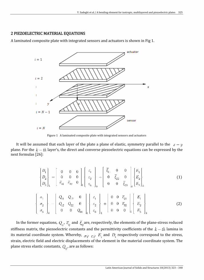
A laminated composite plate with integrated sensors and actuators is shown in Fig 1.
Figure 1 A laminated composite plate with integrated sensors and actuators
It will be assumed that each layer of the plate a plane of elastic, symmetry parallel to the
plane. For the layer’s, the direct and converse piezoelectric equations can be expressed by the next formulas [26]:
(1)
(2)
In the former equations, , and are, respectively, the elements of the plane-stress reduced
stiffness matrix, the piezoelectric constants and the permittivity coefficients of the lamina in its material coordinate system. Whereby, , , and respectively correspond to the stress, strain, electric field and electric displacements of the element in the material coordinate system. The plane stress elastic constants, , are as follows:
Latin American Journal of Solids and Structures 10(2013) 323 – 348
Y. Sadeghi et al / A bending element for isotropic, multilayered and piezoelectric plates
326
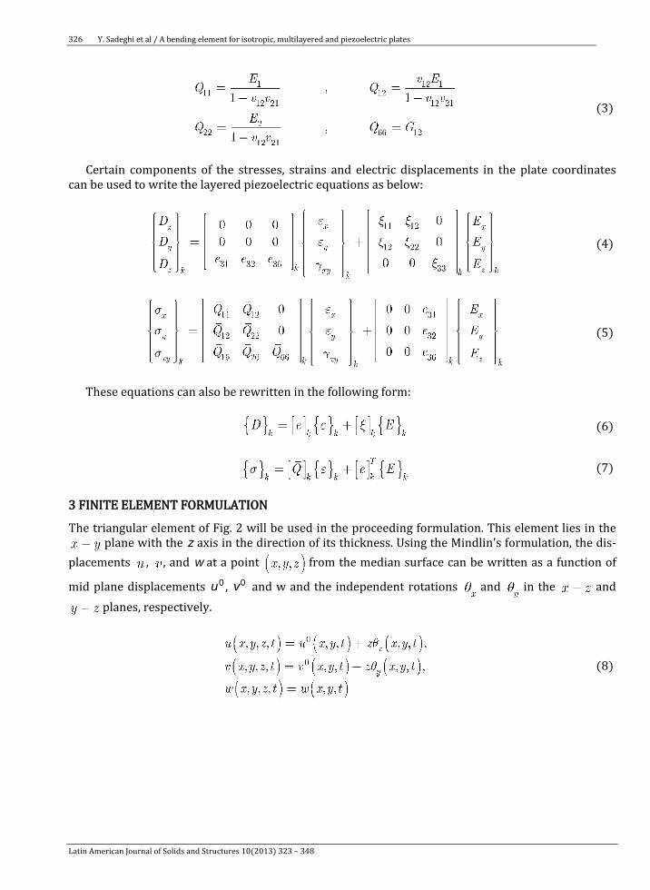
(3)
Certain components of the stresses, strains and electric displacements in the plate coordinates
can be used to write the layered piezoelectric equations as below:
(4)
(5)
These equations can also be rewritten in the following form:
(6)
(7)
3 FINITE ELEMENT FORMULATION
The triangular element of Fig. 2 will be used in the proceeding formulation. This element lies in the plane with the z axis in the direction of its thickness. Using the Mindlin's formulation, the dis-
placements , , and w at a point from the median surface can be written as a function of
mid plane displacements 0u , 0v and w and the independent rotations and in the and planes, respectively.
(8)
Latin American Journal of Solids and Structures 10(2013) 323 – 348
Y. Sadeghi et al / A bending element for isotropic, multilayered and piezoelectric plates 327
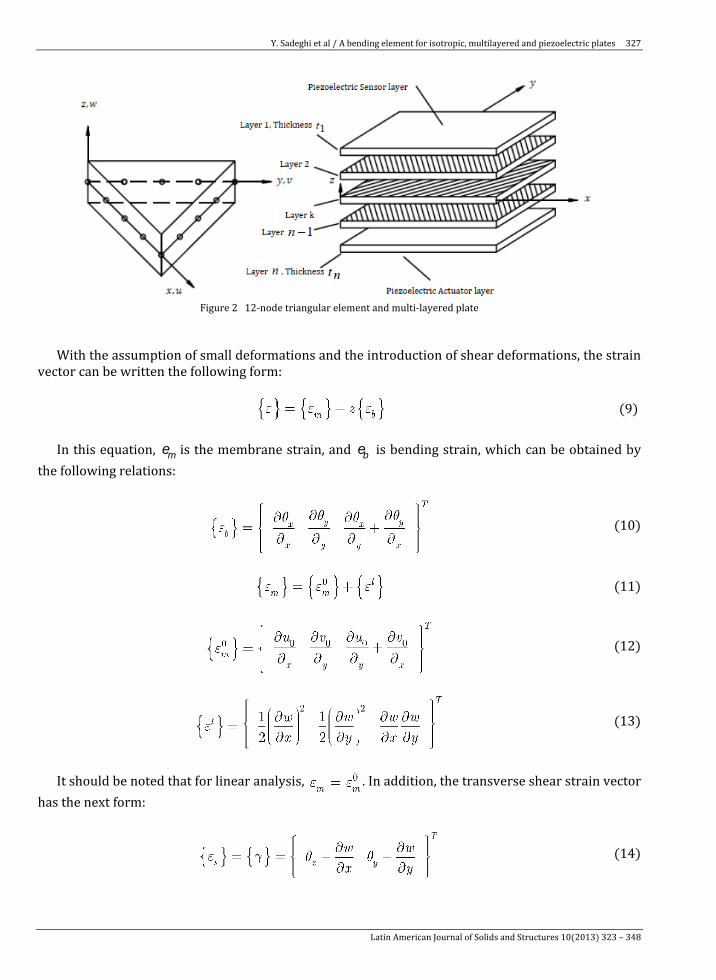
Figure 2 12-node triangular element and multi-layered plate
With the assumption of small deformations and the introduction of shear deformations, the strain vector can be written the following form:
(9)
In this equation, em is the membrane strain, and eb is bending strain, which can be obtained by the following relations:
(10)
(11)
(12)
(13)
It should be noted that for linear analysis, . In addition, the transverse shear strain vector
has the next form:
(14)
Latin American Journal of Solids and Structures 10(2013) 323 – 348
Y. Sadeghi et al / A bending element for isotropic, multilayered and piezoelectric plates
328
In general, the electric field,{ }E , can be assumed in the below shape:
(15)
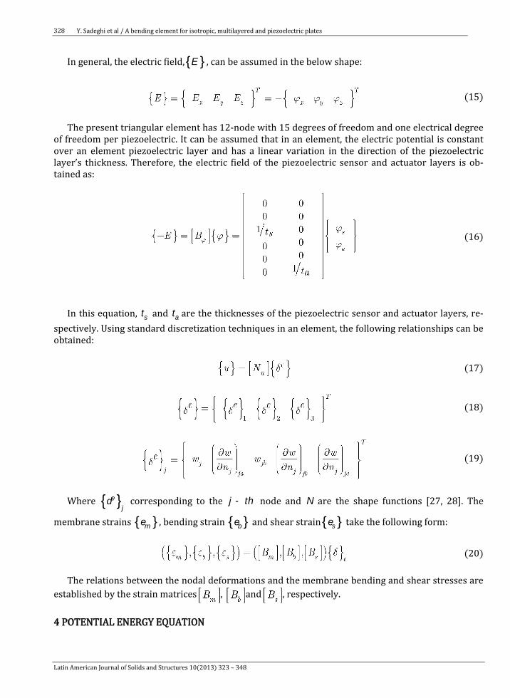
The present triangular element has 12-node with 15 degrees of freedom and one electrical degree
of freedom per piezoelectric. It can be assumed that in an element, the electric potential is constant over an element piezoelectric layer and has a linear variation in the direction of the piezoelectric layer’s thickness. Therefore, the electric field of the piezoelectric sensor and actuator layers is ob-tained as:
(16)
In this equation, st and at are the thicknesses of the piezoelectric sensor and actuator layers, re-spectively. Using standard discretization techniques in an element, the following relationships can be obtained:
(17)
(18)
(19)
Where { }de
j corresponding to the -j th node and N are the shape functions [27, 28]. The
membrane strains { }em , bending strain { }eb and shear strain{ }es take the following form:
(20)
The relations between the nodal deformations and the membrane bending and shear stresses are established by the strain matrices , and , respectively. 4 POTENTIAL ENERGY EQUATION
Latin American Journal of Solids and Structures 10(2013) 323 – 348
Y. Sadeghi et al / A bending element for isotropic, multilayered and piezoelectric plates 329
Based on material properties, the stress-strain relation for piezoelectric composite plates can be written as:
(21)
(22)
(23)
(24)
Here the piezoelectric sensor and actuator layers are considered as an additional layer of a com-
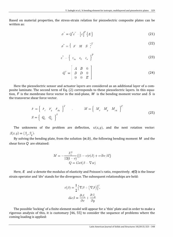
posite laminate. The second term of Eq. (2) corresponds to these piezoelectric layers. In this equa-tion, F is the membrane force vector in the mid-plane, M is the bending moment vector and S is the transverse shear force vector.
(25)
The unknowns of the problem are deflection, , and the next rotation vector:
. By solving the bending plate, from the solution b( , )w , the following bending moment M and the
shear force Q are obtained:
Here, E and u denote the modulus of elasticity and Poisson's ratio, respectively. e(0) is the linear strain operator and ‘div’ stands for the divergence. The subsequent relationships are held:
,
The possible ‘locking’ of a finite element model will appear for a ‘thin’ plate and in order to make a
rigorous analysis of this, it is customary [46, 55] to consider the sequence of problems where the coming loading is applied:
Latin American Journal of Solids and Structures 10(2013) 323 – 348
Y. Sadeghi et al / A bending element for isotropic, multilayered and piezoelectric plates
330
In this equality, f is fixed and independent of the thickness t . Based on this, it is ensured that the
problem has a finite non-vanishing solution in the limit ® 0t . In this limit, the Kirchhoff condition leads to the coming equation:
Accordingly, the locking is due to a too strong enforcement of it in the finite element model. It is also appropriate to consider the scaled shear force -= 3q t Q , in the below form:
The solution to the Reissner-Mindlin equations exhibits a boundary layer (cf. [56] for a survey) and hence the solution will usually not be very smooth even if the loading, and the boundaries are smooth [57].
The relation between the forces and the membrane strains, , and the bending strains, , are given as follows:
(26)
(27)
In this equation, t p is the thickness of the piezoelectric layer. The matrices , and
are extensional, bending extensional and bending stiffness coefficients for the combi-nation of layers, respectively. These matrices are defined next [29]:
(28)
The transverse shear stress of the lamina can be written as follows:
(29)
Thus, the shear force vector S, which appears in all the shear-strain related equations, takes the
following form:
(30)
Latin American Journal of Solids and Structures 10(2013) 323 – 348
Y. Sadeghi et al / A bending element for isotropic, multilayered and piezoelectric plates 331
( )=, 4, 5i j are transverse shear stiffness coefficient, can be obtained by using the following equation.
(31)
In this equation, and are the shear correction factors. Based on the Reissner’s variation
method, one can asume [30]. According to the variation principles, the strain ener-gy equation will take the following form:
(32)
where A is the area of the element, and denotes the volume of the piezoelectric layer in an ele-ment. Substituting , and leads to the next relation:
(33)
It should be noted that represents the element stiffness matrix and is the element
elastic-electric stiffness matrix. 5 ELECTRICAL POTENTIAL EQUATION
Using constitutive relations, strain displacement and electric-field electric-potential relations, the element electrical energy can be written as follows:
(34)
In this equation, represents the elastic electric stiffness matrix and is el-
ement electric stiffness matrix. 6 WORK DONE BY THE EXTERNAL FORCES AND THE ELECTRICAL CHARGE
Latin American Journal of Solids and Structures 10(2013) 323 – 348

Y. Sadeghi et al / A bending element for isotropic, multilayered and piezoelectric plates
332
The virtual work has two components. One component is due to the surface loads and the other com-ponent corresponds to the density of the electric charge. These components are calculated by the following equations:
(35)
where { }f s and { }q are the surface force intensity and surface electric charge density, respectively. The areas where the surface loads and the electric charge are applied to are denoted by 1s and 2s respectively. Eq. (35) can be rewritten in the following form:
(36)
In this equation, represents the mechanical surface load vector, while denotes the
electrical charge in an element. 7 KINETIC ENERGY EQUATION
The element kinetic energy is calculated using the following equation:
(37)
where n is the number of layers, and . Eq. (37) can
be rewritten in the following form:
(38)
In this equation, corresponds to the shape functions and is the element mass matrix.
8 EQUATIONS OF MOTION
Using Hamilton’s principal, an element’s equation of motion can be written in the following form:
(39)
(40)
Latin American Journal of Solids and Structures 10(2013) 323 – 348
Y. Sadeghi et al / A bending element for isotropic, multilayered and piezoelectric plates 333
In this equation, represents the element mass matrix, is the element stiffness ma-
trix, is the element elastic electric stiffness matrix and denotes the ele-
ment electric stiffness matrix [31]. The mechanical force vector and electric charge vector for an ele-ment have been previously defined and are denoted by { }s e
F and { }q eF , respectively. Substituting
Eq. (40) into (39) leads to:
(41)
Eq. (40) is utilized for the sensors when the external charge is equal to zero. Therefore, the input voltage will be equal to:
(42)
Subscript s, denotes the sensor layer. The global equations of motion can be obtained by assem-bling the elemental equations and is given in the following form:
(43)
In the last equation, is the actuator voltage vector, and represents Rayleigh’s damp-ing [32]. 9 NUMERICAL EXAMPLES
The capabilities of the proposed element, as well as its accuracy in analyzing various single-layer bending plate is examined in this section. For this purpose, multiple problems with different geome-tries, layers, boundary conditions and loads will be analyzed. The result of each problem will be com-pared to the elastic solution as well as the results given in other researches. The response of single-layer plates will be examined at first, followed by composite plates and then smart composite plates. In these examples, unless stated otherwise, it is assumed that all the layers of a composite plate have the same thickness. 9.1 Square plate with fixed supports
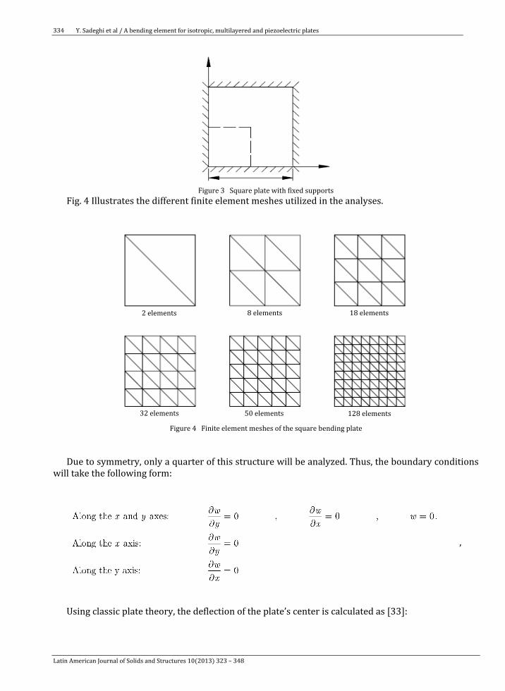
In the first benchmark problem, a square plate with fixed supports and linear behavior will be consi-dered (Fig. 3). The plate will be under a uniform load of q . The length of each side of the plate is equal to L .
Latin American Journal of Solids and Structures 10(2013) 323 – 348
Y. Sadeghi et al / A bending element for isotropic, multilayered and piezoelectric plates
334
Figure 3 Square plate with fixed supports
Fig. 4 Illustrates the different finite element meshes utilized in the analyses.
Figure 4 Finite element meshes of the square bending plate
Due to symmetry, only a quarter of this structure will be analyzed. Thus, the boundary conditions will take the following form:
,
Using classic plate theory, the deflection of the plate’s center is calculated as [33]:
128 elements 50 elements 32 elements
2 elements 8 elements 18 elements
Latin American Journal of Solids and Structures 10(2013) 323 – 348
Y. Sadeghi et al / A bending element for isotropic, multilayered and piezoelectric plates 335
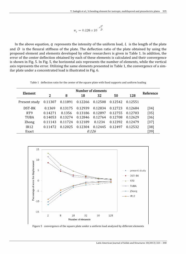
In the above equation, q represents the intensity of the uniform load, L is the length of the plate
and D is the flexural stiffness of the plate. The deflection ratio of the plate obtained by using the proposed element and elements developed by other researchers is given in Table 1. In addition, the error of the center deflection obtained by each of these elements is calculated and their convergence is shown in Fig. 5. In Fig. 5, the horizontal axis represents the number of elements, while the vertical axis represents the error. Utilizing the same elements presented in Table 1, the convergence of a sim-ilar plate under a concentrated load is illustrated in Fig. 6.
Table 1 deflection ratio for the center of the square plate with fixed supports and uniform loading
Reference Number of elements Element 128 50 32 18 8 2
0.12551 0.12542 0.12508 0.12266 0.11891 0.11307 Present study
[34] 0.12684 0.12723 0.12834 0.12939 0.13175 0.1369 DST-BK [35] 0.12703 0.12755 0.12897 0.13186 0.1356 0.14271 RT9 [36] 0.12629 0.12708 0.12764 0.12846 0.13274 0.14053 TUBA [37] 0.12479 0.12392 0.1234 0.12189 0.11724 0.11143 Zhong [38] 0.12532 0.12497 0.12445 0.12304 0.12025 0.11472 IR12 [39] 0.126 Exact
Figure 5 convergence of the square plate under a uniform load analyzed by different elements
Latin American Journal of Solids and Structures 10(2013) 323 – 348

Y. Sadeghi et al / A bending element for isotropic, multilayered and piezoelectric plates
336
Figure 6 convergence of the square plate under a concentrated loading analyzed by different elements
It is evident from Table 1 and Figs. (5) and (6) that the proposed element is capable of resulting in fairly accurate results. However, in order to make a more comprehensive assessment of the capabili-ties of the element, more complex problems should also be solved. 9.2 Inclined plate with fixed edges
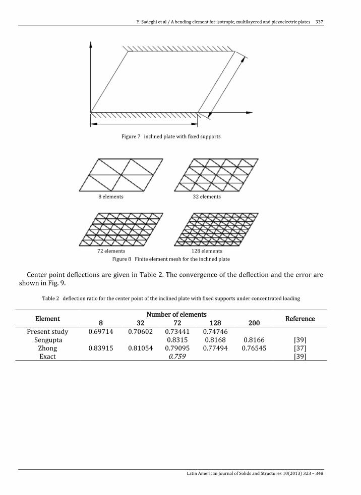
A plate with a 30º inclination will be considered in this section. As illustrated in Fig. 7, this structure is fixed along two sides the x axis and parallel to the x axis and is free along the other two sides. The concentrated load P is applied at the center of the plate. Boundary conditions corresponding to the fixed edges are as follows:
Fig. 8 illustrates the different finite element meshes used for linear analysis of the inclined plate.
The deflection of the plate’s center point is calculated by the following equation:
Latin American Journal of Solids and Structures 10(2013) 323 – 348
Y. Sadeghi et al / A bending element for isotropic, multilayered and piezoelectric plates 337
Figure 7 inclined plate with fixed supports
Figure 8 Finite element mesh for the inclined plate Center point deflections are given in Table 2. The convergence of the deflection and the error are shown in Fig. 9.
Table 2 deflection ratio for the center point of the inclined plate with fixed supports under concentrated loading
Reference Number of elements Element 200 128 72 32 8 0.74746 0.73441 0.70602 0.69714 Present study
[39] 0.8166 0.8168 0.8315 Sengupta [37] 0.76545 0.77494 0.79095 0.81054 0.83915 Zhong [39] 0.759 Exact
8 elements 32 elements
72 elements 128 elements
Latin American Journal of Solids and Structures 10(2013) 323 – 348
Y. Sadeghi et al / A bending element for isotropic, multilayered and piezoelectric plates
338
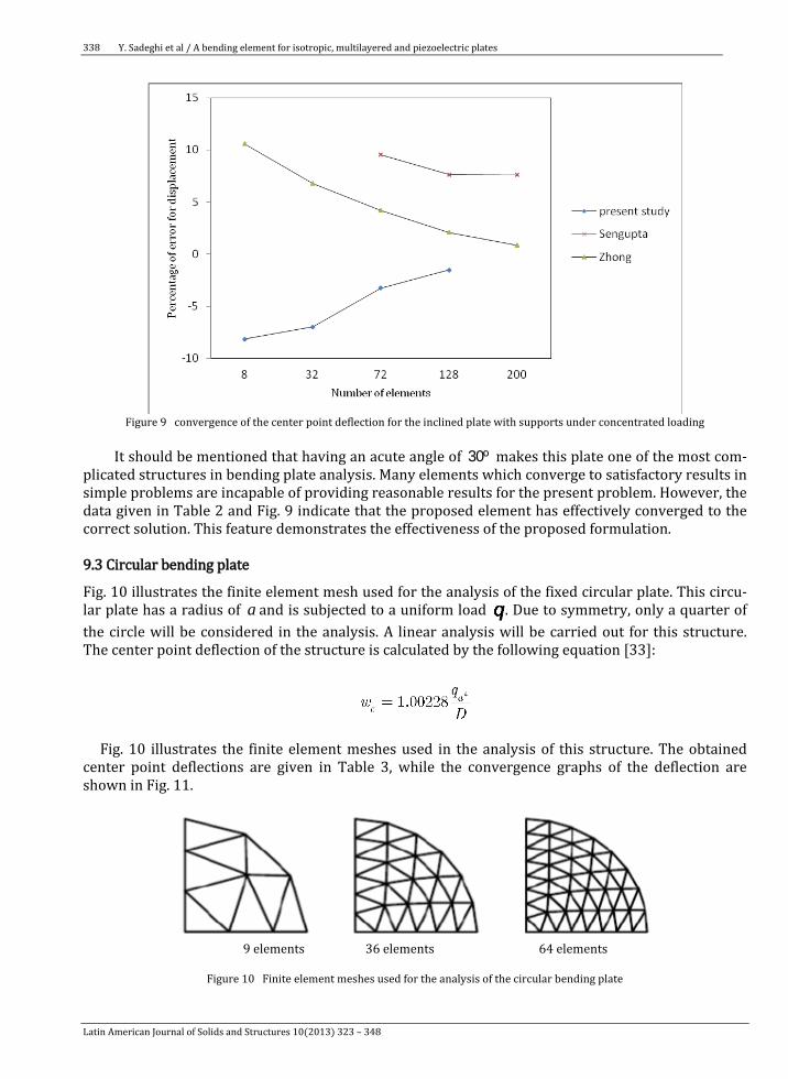
Figure 9 convergence of the center point deflection for the inclined plate with supports under concentrated loading
It should be mentioned that having an acute angle of 30º makes this plate one of the most com-
plicated structures in bending plate analysis. Many elements which converge to satisfactory results in simple problems are incapable of providing reasonable results for the present problem. However, the data given in Table 2 and Fig. 9 indicate that the proposed element has effectively converged to the correct solution. This feature demonstrates the effectiveness of the proposed formulation. 9.3 Circular bending plate
Fig. 10 illustrates the finite element mesh used for the analysis of the fixed circular plate. This circu-lar plate has a radius of a and is subjected to a uniform load . Due to symmetry, only a quarter of the circle will be considered in the analysis. A linear analysis will be carried out for this structure. The center point deflection of the structure is calculated by the following equation [33]:
Fig. 10 illustrates the finite element meshes used in the analysis of this structure. The obtained center point deflections are given in Table 3, while the convergence graphs of the deflection are shown in Fig. 11.
9 elements 36 elements 64 elements
Figure 10 Finite element meshes used for the analysis of the circular bending plate
Latin American Journal of Solids and Structures 10(2013) 323 – 348
Y. Sadeghi et al / A bending element for isotropic, multilayered and piezoelectric plates 339
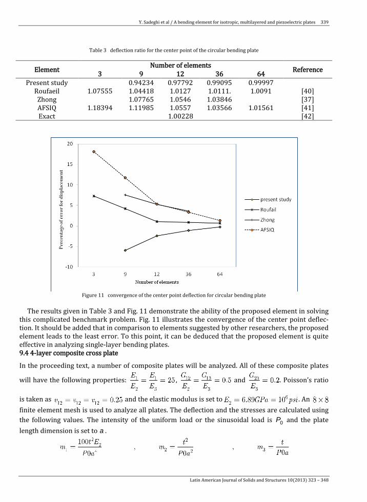
Table 3 deflection ratio for the center point of the circular bending plate
Reference Number of elements Element 64 36 12 9 3 0.99997 0.99095 0.97792 0.94234 Present study
[40] 1.0091 .1.0111 1.0127 1.04418 1.07555 Roufaeil [37] 1.03846 1.0546 1.07765 Zhong [41] 1.01561 1.03566 1.0557 1.11985 1.18394 AFSIQ [42] 1.00228 Exact
Figure 11 convergence of the center point deflection for circular bending plate
The results given in Table 3 and Fig. 11 demonstrate the ability of the proposed element in solving this complicated benchmark problem. Fig. 11 illustrates the convergence of the center point deflec-tion. It should be added that in comparison to elements suggested by other researchers, the proposed element leads to the least error. To this point, it can be deduced that the proposed element is quite effective in analyzing single-layer bending plates. 9.4 4-layer composite cross plate
In the proceeding text, a number of composite plates will be analyzed. All of these composite plates
will have the following properties: , and . Poisson’s ratio
is taken as and the elastic modulus is set to . An finite element mesh is used to analyze all plates. The deflection and the stresses are calculated using the following values. The intensity of the uniform load or the sinusoidal load is 0P and the plate length dimension is set to a .
Latin American Journal of Solids and Structures 10(2013) 323 – 348
Y. Sadeghi et al / A bending element for isotropic, multilayered and piezoelectric plates
340
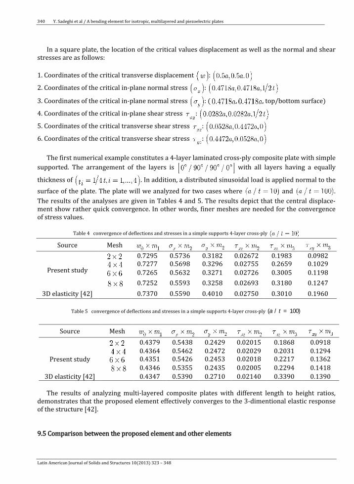
In a square plate, the location of the critical values displacement as well as the normal and shear
stresses are as follows: 1. Coordinates of the critical transverse displacement :
2. Coordinates of the critical in-plane normal stress :
3. Coordinates of the critical in-plane normal stress : ( , , top/bottom surface)
4. Coordinates of the critical in-plane shear stress :
5. Coordinates of the critical transverse shear stress :
6. Coordinates of the critical transverse shear stress :
The first numerical example constitutes a 4-layer laminated cross-ply composite plate with simple supported. The arrangement of the layers is with all layers having a equally
thickness of . In addition, a distributed sinusoidal load is applied normal to the surface of the plate. The plate will we analyzed for two cases where and . The results of the analyses are given in Tables 4 and 5. The results depict that the central displace-ment show rather quick convergence. In other words, finer meshes are needed for the convergence of stress values.
Table 4 convergence of deflections and stresses in a simple supports 4-layer cross-ply
Mesh Source 0.0982 0.1983 0.02672 0.3182 0.5736 0.7295
Present study 0.1029 0.2659 0.02755 0.3296 0.5698 0.7277 0.1198 0.3005 0.02726 0.3271 0.5632 0.7265 0.1247 0.3180 0.02693 0.3258 0.5593 0.7252 0.1960 0.3010 0.02750 0.4010 0.5590 0.7370 3D elasticity [42]
Table 5 convergence of deflections and stresses in a simple supports 4-layer cross-ply =( / 100)a t
Mesh Source
0.0918 0.1868 0.02015 0.2429 0.5438 0.4379
Present study
0.1294 0.2031 0.02029 0.2472 0.5462 0.4364 0.1362 0.2217 0.02018 0.2453 0.5426 0.4351 0.1418 0.2294 0.02005 0.2435 0.5355 0.4346 0.1390 0.3390 0.02140 0.2710 0.5390 0.4347 3D elasticity [42]
The results of analyzing multi-layered composite plates with different length to height ratios,
demonstrates that the proposed element effectively converges to the 3-dimentional elastic response of the structure [42].
9.5 Comparison between the proposed element and other elements
Latin American Journal of Solids and Structures 10(2013) 323 – 348
Y. Sadeghi et al / A bending element for isotropic, multilayered and piezoelectric plates 341
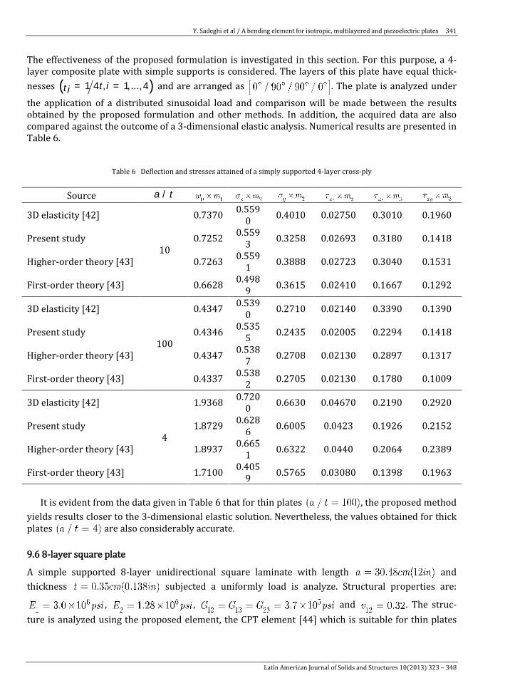
The effectiveness of the proposed formulation is investigated in this section. For this purpose, a 4-layer composite plate with simple supports is considered. The layers of this plate have equal thick-nesses ( )= =1 4 , 1,...,4t it i and are arranged as . The plate is analyzed under
the application of a distributed sinusoidal load and comparison will be made between the results obtained by the proposed formulation and other methods. In addition, the acquired data are also compared against the outcome of a 3-dimensional elastic analysis. Numerical results are presented in Table 6.
Table 6 Deflection and stresses attained of a simply supported 4-layer cross-ply
/a t Source
0.1960 0.3010 0.02750 0.4010 0.5590 0.7370
10
3D elasticity [42]
0.1418 0.3180 0.02693 0.3258 0.5593 0.7252 Present study
0.1531 0.3040 0.02723 0.3888 0.5591 0.7263 Higher-order theory [43]
0.1292 0.1667 0.02410 0.3615 0.4989 0.6628 First-order theory [43]
0.1390 0.3390 0.02140 0.2710 0.5390 0.4347
100
3D elasticity [42]
0.1418 0.2294 0.02005 0.2435 0.5355 0.4346 Present study
0.1317 0.2897 0.02130 0.2708 0.5387 0.4347 Higher-order theory [43]
0.1009 0.1780 0.02130 0.2705 0.5382 0.4337 First-order theory [43]
0.2920 0.2190 0.04670 0.6630 0.7200 1.9368
4
3D elasticity [42]
0.2152 0.1926 0.0423 0.6005 0.6286 1.8729 Present study
0.2389 0.2064 0.0440 0.6322 0.6651 1.8937 Higher-order theory [43]
0.1963 0.1398 0.03080 0.5765 0.4059 1.7100 First-order theory [43]
It is evident from the data given in Table 6 that for thin plates , the proposed method
yields results closer to the 3-dimensional elastic solution. Nevertheless, the values obtained for thick plates are also considerably accurate. 9.6 8-layer square plate
A simple supported 8-layer unidirectional square laminate with length and thickness subjected a uniformly load is analyze. Structural properties are:
, , and . The struc-ture is analyzed using the proposed element, the CPT element [44] which is suitable for thin plates
Latin American Journal of Solids and Structures 10(2013) 323 – 348
Y. Sadeghi et al / A bending element for isotropic, multilayered and piezoelectric plates
342
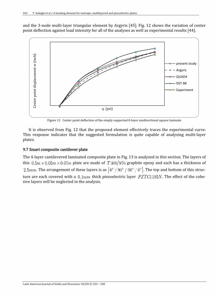
and the 3-node multi-layer triangular element by Argyris [45]. Fig. 12 shows the variation of center point deflection against load intensity for all of the analyses as well as experimental results [44].
Figure 12 Center point deflection of the simply supported 8-layer unidirectional square laminate
It is observed from Fig. 12 that the proposed element effectively traces the experimental curve.
This response indicates that the suggested formulation is quite capable of analyzing multi-layer plates. 9.7 Smart composite cantilever plate
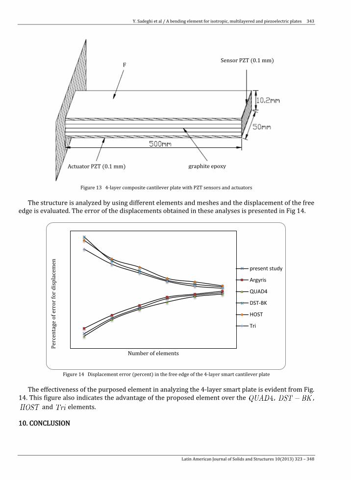
The 4-layer cantilevered laminated composite plate in Fig. 13 is analyzed in this section. The layers of this plate are made of graphite epoxy and each has a thickness of
. The arrangement of these layers is as . The top and bottom of this struc-ture are each covered with a thick piezoelectric layer . The effect of the cohe-sive layers will be neglected in the analysis.
Cent
er p
oint
dis
plac
emen
t w (i
nch)
q (psi)
present study
Argyris
QUAD4
DST-BK
Experiment
Latin American Journal of Solids and Structures 10(2013) 323 – 348
Y. Sadeghi et al / A bending element for isotropic, multilayered and piezoelectric plates 343
Figure 13 4-layer composite cantilever plate with PZT sensors and actuators
The structure is analyzed by using different elements and meshes and the displacement of the free
edge is evaluated. The error of the displacements obtained in these analyses is presented in Fig 14.
Figure 14 Displacement error (percent) in the free edge of the 4-layer smart cantilever plate
The effectiveness of the purposed element in analyzing the 4-layer smart plate is evident from Fig. 14. This figure also indicates the advantage of the proposed element over the , ,
and elements. 10. CONCLUSION
Perc
enta
ge o
f err
or fo
r dis
plac
emen
Number of elements
present study
Argyris
QUAD4
DST-BK
HOST
Tri
Sensor PZT (0.1 mm) F
graphite epoxy Actuator PZT (0.1 mm)
Latin American Journal of Solids and Structures 10(2013) 323 – 348
Y. Sadeghi et al / A bending element for isotropic, multilayered and piezoelectric plates
344
A 12-node triangular element was formulated for the analysis of multi-layered bending plates. The formulation was based on the Mindlin’s first-order shear deformation theory, and an elastic piezoe-lectric behavior is considered for the material. The developed relations are capable of effectively analyzing both thin and thick plates. Several benchmark problems were analyzed using the proposed element. It was demonstrated via numerical analysis that this new element can be utilized for the analysis of single- and multi-layered plates with and without a piezoelectric layer. Moreover, the numerical results indicate that the suggested element is capable of converging to the exact solution. In comparison to the results given by other researchers, it was deduced that the authors' formulation leads to faster convergence. References [1] R.E. Newnham, L.J. Bowen, K.A. Klicker, L.E. Cross, “Composite piezoelectric transducers. Material
design. 1998; 2: 93-106. [2] J.N. Reddy, On laminated composite plates with integrated sensors and actuators. Engineer
struct. 1999; 21: 568-593. [3] C.K. Lee, Theory of laminated piezoelectric plates for the design of distributed sensors/actuators.
Part I: Governing equations and reciprocal relationships. Acoust. Soc Amer. 1990; 87:1144-1158.
[4] E.F. Crawley, K.B. Lazarus, Induced strain actuation of isotropic and anisotropic plates. AIAA J. 1991; 29: 944-951.
[5] H.S. Tzou, C.I. Tseng, Distributed modal identification and vibration control of continua: Piezoe-lectric finite element formulation and analysis. ASME J. 1991; 113 : 500-505.
[6] S.K. Ha, C. Keilers, F.K. Chang, Finite element analysis of composite structures containing distrib-uted piezoceramic sensors and actuators. AIAA J. 1998; 30: 772-780.
[7] W.S. Hwang, H.C. Park, Finite element modeling of piezoelectric sensors and actuators. AIAA J. 1993; 31: 930-937.
[8] D.T. Detwiler, M.H.H. Shen, V.B. Venkayya, Finite element analysis of laminated composite struc-tures containing distributed piezoelectric actuators and sensors. Finite Elements Anal. 1995; 20: 87-100.
[9] Z. Wang, S. Chen, W. Han, Static shape control for intelligent structures. Finite Elements Anal. 1997; 26: 303-314.
[10] M. Salehi, A. Shahidi, Elastic Large Deflection Analysis of Elastic Sector Mindlin Plates. Comp. Struc.,1994; 52; 987-989.
[11] A. Benjeddou, Advances in piezoelectric finite element modeling of adaptive structural elements: a survey. Comp. Struc., 2000; 76; 347-363.
[12] P. Kumari and S. Kapuria, Boundary layer effects in rectangular cross-ply Levy-type plates using zigzag theory. ZAMM · Z. Angew. Math. Mech. 2011; 91; 565-580.
[13] G.J. Turvey, M. Salehi, Elasto-plastic Response of Uniformly Loaded Sector Plates: Full Section Yield Model Prediction and Spread of Plasticity. Comp. Struc., 2001; 79; 2335-2348.
[14] S. Goswami, A C0 plate bending element with refined shear deformation theory for composite structures. Compos. Struc. ,2006; 72;375-382.
[15] Dimitris Varelis, Dimitris A. Saravanos, Coupled mechanics and finite element for non-linear laminated piezoelectric shallow shells undergoing large displacements and rotations. Num. Meth. Engine. 2006; 66;1211–1233.
[16] H. Santos, M. Soares, A. Carlos, J.N. Reddy, A finite element model for the analysis of 3D axisym-metric laminated shells with piezoelectric sensors and actuators. Compos. Struc. ,2006; 75;170-178.
[17] M. Aydogdu, A new shear deformation theory for laminated composite plates. Compos. Struc. ,2008; 53; 215-231.
Latin American Journal of Solids and Structures 10(2013) 323 – 348

Y. Sadeghi et al / A bending element for isotropic, multilayered and piezoelectric plates 345
[18] C.K. Kundu, D.K. Maiti, P.K. Sinha, Post buckling analysis of smart laminated doubly curved shells. Compos. Struc. 2007; 81; 314-322.
[19] H. Tanriover, E. Senocak, Larg Deflection Analysis of Unsymmetrically Laminated Composite Plates: Analytical- Numerical Type Approach. International Journal of Non- Linear Mechanics. 2004; 39; 1385-1392.
[20] M. C etkovic, Dj. Vuksanovic, Bending, free vibrations and buckling of laminated composite and sandwich plates using a layerwise displacement model. Compos. Struc. ,2008; 62; 578-592.
[21] P. C. Dumir, S. Kapuria, P. Kumari, and J.K. Nath, Two-dimensional benchmark solution for buck-ling and vibration of simply supported hybrid piezoelectric angle-ply flat panels. ZAMM · Z. An-gew. Math. Mech.2008; 88; 42-57.
[22] M. Salehi, A.R. Sobhani, Elastic Linear and Non- Linear Analysis of Fiber- Reinforced Symmetri-cally Laminated Sector Mindlin Plates. Comp. Struc., 2004; 65; 65-79.
[23] Z. Tian, D. Wang, A method for treating nonconforming thin plate bending problems. Finite Ele-ments Anal. 2011; 47; 200-207.
[24] H. Nguyen-Xuan, G.R. Liu, C. Thai-Hoang, An edge-based smoothed finite element method with stabilized discrete shear gap technique for analysis of Reissner–Mindlin plates. Comp. Meth. Appl. Mech. Eng., 2010; 199; 471–489.
[25] N. Nguyen-Thanha, T. Rabczuka, H. Nguyen-Xuan, An alternative alpha finite element method with discrete shear gap technique for analysis of isotropic Mindlin–Reissner plates. Finite Ele-ments Anal. 2011; 47; 519-535.
[26] J. N. Reddy, Mechanics of Laminated Plates Theory and Analysis. Mc Graw-Hill, New York, 1997. [27] B.P. Naganarayana, G. Prathap, B. Dattaguru, B.S. Ramamurthy, A field consistent and variational-
ly correct representation of transverse shear strain in nine noded plate element. Comput Struct. 1999; 97: 355-374.
[28] G. Prathap, Recent advances in finite element techniques. Mc Graw-Hill, New York, 1998. [29] R.M. Jones, Mechanics of Composite Materials. Mc Graw-Hill, New York, 1995. [30] Z. Wang, S. Chen, W. Han, Static shape control for intelligent structures. Finite Elements Anal.
2000; 26: 303-314. [31] S. Kapuria, S.D. Kulkarni, An efficient quadrilateral element based on improved zigzag theory for
dynamic analysis of hybrid plates with electrode piezoelectric actuators and sensors. Journal of Sound and Vibration; 2008; 315; 118-145.
[32] D.T. Detwiler, M.H.H. Shen, V.B. Venkayya, Finite element analysis of laminated composite struc-tures containing distributed piezoelectric actuators and sensors. Finite Elements Anal. 2005; 20: 87-100.
[33] Timoshenko, S. P., Woinowsky, Theory of plates and shells, Mc Graw-Hill, New York, (1959). [34] Batoz J. L., Katili I., On a simple triangular Reissner – Mindlin plate element based on incompati-
ble modes and discrete constraints, Numerical Methods in Engineering 1992; 35: 1603-1632. [35] Cheung Y. K., Wanji C, Refined Nine – Parameter triangular thin plate bending element by using
refined direct stiffness method, Numerical Methods in Engineering 1995; 38: 283-298. [36] Ming P. G., A new element use in the non – orthogonal boundary plate bending theory – an arbi-
trarily quadrilateral element, Numerical Methods in Engineering 1987; 24: 1031-1042. [37] Zhongnian X., A thick – thin triangular plate element, Numerical Methods in Engineering 1992;
33: 963-937. [38] Torres J., Samartin A., Arroyo V, A C1 finite element family for kirchoff plate bending, Numerical
Methods in Engineering 1986; 23: 2005-2029. [39] Sengupta D., Performance study of a simple finite element in the analysis of skew rhombic
plates, Computer & Structure 1995; 54: 1173-1182. [40] Roufaeil, O. L., A new four node quadrilateral plate bending element, Int. J. Comp. Struc.1995; 54;
871-879.
Latin American Journal of Solids and Structures 10(2013) 323 – 348

Y. Sadeghi et al / A bending element for isotropic, multilayered and piezoelectric plates
346
[41] Zhenfeng Zhao, Wanji C., New finite element model for analysis of Kirchhoff plate, Numerical Methods in Engineering 1995; 38: 1201-1214.
[42] Pagano NJ, Hatfield SJ. Elastic behaviour of multilayered bidirectional composites. AIAA J. 1972; 10: 931–939.
[43] Reddy JN. A simple higher order theory for laminated composite plates. ASME J Appl Mech. 1984; 51: 745–752.
[44] Zaghloul SA, Kennedy JB. Nonlinear behavior of symmetrically laminated plates. J Appl Mech. 1975; 42: 234–246.
[45] Argyris J, Tenek L. Linear and geometrically nonlinear bending of isotropic and multilayered composite plates by the natural mode method. Comput Meth Appl Mech Eng. 1994; 113: 207–223.
[46] T.J.R Hughes and L.P. Franca. A mixed finite element formulation for Reissner-Mindlin plate the-ory: Uniform convergence of all higher-order spaces. Comput. Methods Appl. Mech. Engrg. 1988; 67: 223-240.
[47] D.asry and T.Belytschko , Transverse shear oscillations in four –node quadrilateral plate ele-ments, Comput. & Structures 1987;27: 393-398.
[48] D.N. Arnold and R.S Falk , A uniformly accurate finite element method for the Reissner-Mindlin plate. SIAM J. Numer. Anal. 1989; 26: 1267-1290.
[49] K.J. Bathe and F.Brezzi, On the convergence of a four node plate bending element based on Reissner-Mindlin theory, in: J.R. Whiteman. Ed. The Mathematics of Finite Elements Applications V. MAFELAP 1984 (Academic Press.New York, 1985) 491-503.
[50] K.J. Bathe and F. Brezzi, A simplified analysis of two plate bending elements- The MITC4 and MITC9 elements, in: G.N. Pande and J. Middleton. Eds. NUMETA 87, Vol. 1, Numerical Techniques for Engineering Analysis and Design (Martinus Nijhoff. Dordrecht, 1987) D46/1.
[51] K.J. Bathe, F. Brezzi and M. Fortin. Mixed-interpolated elements for Reissner-Mindlin plates. In-ternat. J. Numer. Methods Engrg. 1989; 28: 1787-1801.
[52] F.Brezzi . M. Fortin and R. Stenberg. Error analysis of mixed-interpolated elements for Reissner-Mindlin plates. Math. Models Methods Appl. Sci. 1991; 1: 125-151.
[53] L.P. Franca and R. Stenberg. A modification of a low-order Reissner-Mindlin plate bending ele-ment. In: J.R. Whiteman, ed. The Mathematics of Finite Elements and Application VII. MAFELAP 1990 (Academic Press. New York, 1991) 425-436.
[54] J. Pitkaranta. Analysis of some low-order finite element schemes for Mindlin-Reissner and Kirchhoff plates. Numer. Math. 1988; 53: 237-254.
[55] F. Brezzi and M. Fortin. Numerical approximation of Mindlin-Reissner plates. Math. Comp. 1986; 47: 151-158.
[56] D. N. Arnold and R. S. Falk. Edge effects in the Reissner-Mindlin plate theory. In: A. K. Noor. T. Belytschko and J. C. Simo, eds. Analytical and Computational Models of Shells (ASME. New York, 1989) 71-89.
[57] M. Lyly, R. Stenberg and T. Vihinen. A stable bilinear element for tha Reissner-Mindlin plate model. Com. Meth. Applied Mechanics and Engineering 1993; 110: 343-357.
Latin American Journal of Solids and Structures 10(2013) 323 – 348