Multilayered Optical Feedback for Controlling...
5
IJCSN - International Journal of Computer Science and Network, Volume 3, Issue 6, December 2014 ISSN (Online): 2277-5420 www.IJCSN.org Impact Factor: 0.274 563 Multilayered Optical Feedback for Controlling Haptic Devices 1 Jit Sen Gupta, 2 Suman Deb, 3 Ashim Saha 1, 2, 3 Computer Science and Engineering, National Institute of Technology-Agartala, Agartala, 799055, India Abstract - For outdoor painting or graphics designing till date only manual approach are used. In the current era of modernization involvement of smart devices can be seen in every field. So the involvement of such devices in the field of painting or graphics design is very much necessary. This paper is mainly focused on the designing and improvising of such automatic system for solving such problems. The main significance of such devices is that it can design a graphics of very large size and on any surface or platform. It can be done simply by changing the attachments. Further, the system can be changed in order to have its application in various different areas such as painting a large football field or in paleontological study. Keywords - Arduino, Edge detection, multilayered optical feedback, Dual H-Bridge, Haptic device. 1. Introduction Now days for painting and graphics either we have to consult a trained person or painter or printing devices. But printing on uneven surface or except paper can only be done by expert persons that will consume a lot of time may have mistakes .if the expert person is not available then we have to wait then its again a wastage of time. So in order to overcome such problem some device can be made which can perform the same task in more efficient way. Hence the necessity of such devices put us to think for designing such type of devices. In order to design such type of devices we will need an intelligent system, which can think like humans & do the task in the same way a human do. This can be done using haptic devices with the interaction of computers. With the use of simple hardware components like Arduino board and a motor shield this can be made possible to have the desired haptic effect [1]. Most of the work done previously in this field uses DC motor which is having controlling problem hence in our work Johnson geared wheels is used. Our work is focused on drawing pattern of the given design. For that we are using edge detection algorithm to find the edges. A multilayered concept is also introduced to check the correctness of the device based on which the system also gets a real-time optical feedback of the device based on that the system updates itself to work the haptic device accordingly. The experiment result shows that a variety of patterns can be generated by this proposed tool. In Section 2 comprises of some work being done using the similar concept. In Section 3 the system overview is presented. Techniques and working concept of this system is described in Section 4. Further in Section 5 conclusions and future works are formulated. 2. Related Works Similar concept related to this idea has been used to develop a system which is wirelessly controlled via an Android device (such as a Smartphone or a tablet) [2] by a group of research people from New York Institute of Technology. The system is meant for search mission under the rubbles in the occurrence of natural disasters. The device used by them is small enough to maneuver and pass through tight spaces. As due to the light weight of the device it can move over the rubbles without risking the lives of possible survivors. This system uses sensors which consumes a lot of energy as well as have higher cost. In another work a Wall painting robot [3] is used for picture painting in the outer walls, cleaning, tile separation sensing and repair work without the involvement of humans to minimize the risk of life of people working in civil structure construction. But the main demerit of this system is that it needs a huge set up for proper functioning. A smart camera system [4] has been developed for advanced digital paint systems, based on accurate simulation models for the paint, brush and canvas interaction enable a virtual painting environment familiar to artists. In this, one has to sit and paint the graphics projected by the projector. Hence it needs throughout involvement of human for completing its task.
Transcript of Multilayered Optical Feedback for Controlling...
IJCSN - International Journal of Computer Science and Network, Volume 3, Issue 6, December 2014 ISSN (Online): 2277-5420 www.IJCSN.org Impact Factor: 0.274
563
Multilayered Optical Feedback for Controlling Haptic
Devices
1 Jit Sen Gupta, 2 Suman Deb, 3Ashim Saha
1, 2, 3 Computer Science and Engineering, National Institute of Technology-Agartala,
Agartala, 799055, India
Abstract - For outdoor painting or graphics designing till date
only manual approach are used. In the current era of modernization involvement of smart devices can be seen in every field. So the involvement of such devices in the field of painting or graphics design is very much necessary. This paper is mainly
focused on the designing and improvising of such automatic system for solving such problems. The main significance of such devices is that it can design a graphics of very large size and on any surface or platform. It can be done simply by changing the attachments. Further, the system can be changed in order to have its application in various different areas such as painting a large football field or in paleontological study.
Keywords - Arduino, Edge detection, multilayered optical
feedback, Dual H-Bridge, Haptic device.
1. Introduction
Now days for painting and graphics either we have to
consult a trained person or painter or printing devices. But printing on uneven surface or except paper can only be
done by expert persons that will consume a lot of time
may have mistakes .if the expert person is not available
then we have to wait then its again a wastage of time. So
in order to overcome such problem some device can be
made which can perform the same task in more efficient
way. Hence the necessity of such devices put us to think
for designing such type of devices.
In order to design such type of devices we will need an
intelligent system, which can think like humans & do the task in the same way a human do. This can be done using
haptic devices with the interaction of computers. With the
use of simple hardware components like Arduino board
and a motor shield this can be made possible to have the
desired haptic effect [1]. Most of the work done previously
in this field uses DC motor which is having controlling
problem hence in our work Johnson geared wheels is used.
Our work is focused on drawing pattern of the given
design. For that we are using edge detection algorithm to
find the edges. A multilayered concept is also introduced
to check the correctness of the device based on which the
system also gets a real-time optical feedback of the device
based on that the system updates itself to work the haptic
device accordingly. The experiment result shows that a
variety of patterns can be generated by this proposed tool.
In Section 2 comprises of some work being done using the
similar concept. In Section 3 the system overview is presented. Techniques and working concept of this system
is described in Section 4. Further in Section 5 conclusions
and future works are formulated.
2. Related Works
Similar concept related to this idea has been used to develop a system which is wirelessly controlled via an
Android device (such as a Smartphone or a tablet) [2] by a
group of research people from New York Institute of
Technology. The system is meant for search mission under
the rubbles in the occurrence of natural disasters. The
device used by them is small enough to maneuver and pass
through tight spaces. As due to the light weight of the
device it can move over the rubbles without risking the
lives of possible survivors. This system uses sensors which
consumes a lot of energy as well as have higher cost.
In another work a Wall painting robot [3] is used for picture painting in the outer walls, cleaning, tile separation
sensing and repair work without the involvement of
humans to minimize the risk of life of people working in
civil structure construction. But the main demerit of this
system is that it needs a huge set up for proper functioning.
A smart camera system [4] has been developed for
advanced digital paint systems, based on accurate
simulation models for the paint, brush and canvas
interaction enable a virtual painting environment familiar
to artists.
In this, one has to sit and paint the graphics projected by
the projector. Hence it needs throughout involvement of
human for completing its task.
IJCSN - International Journal of Computer Science and Network, Volume 3, Issue 6, December 2014 ISSN (Online): 2277-5420 www.IJCSN.org Impact Factor: 0.274
564
3. System Overview
3.1. Edge Detection
The main task of the system would be to get the pattern of
the given image, for that we have to detect the edges of
that image which can be done by various edge detection
techniques. The significance of these techniques is that it helps in identifying the edges of an input image, for that it
is very essential to know the advantages of all edge
detection algorithms. Here we are using Canny’s edge
detection algorithm as it has better performance in
comparison with Sobel, Prewitt and Robert’s
operator[5][6].
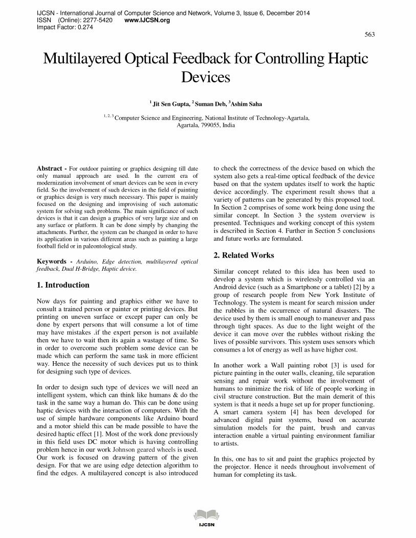
Fig.1: Flow chart of canny edge detection algorithm
Smoothing: Noise contained in image is smoothed by
convolving the input image I (i, j) with Gaussian filter G. As the Canny edge detection algorithm is susceptible to
noise present in unprocessed image data, hence it uses a
filter based on a Gaussian (bell) curve, where the raw
image is convolved with a Gaussian filter. The result F(i,j) (eq. 1) is a slightly blurred version of the original which is
not affected by a single noisy pixel to any significant
degree. Mathematically, the smooth resultant image is
given by
F(i,j)=G*I(i,j) (1)
Computing Gradients: An edge in an image may point in
a variety of directions, so the Canny algorithm uses four
filters to detect horizontal, vertical and diagonal edges in
the blurred image. The edge detection operator returns a
value for the first derivative in the horizontal direction (Gx) and the vertical direction (Gy). From this the edge
gradient and direction can be determined:
G=���� +��� (2)
ΘΘΘΘ=arctan(����) (3)
Where G can be computed using the hypot function (eq. 2)
and arctan is the arctangent function (eq. 3) with two
arguments. The edge direction angle is rounded to one of
four angles representing vertical, horizontal and the two
diagonals.
Non Maximum Suppression: It is an edge thinning
technique. For a pixel M (i, j):
In Firstly round the gradient direction Θ nearest45°, then compare the gradient magnitude of the pixels in positive
and negative gradient directions i.e. If gradient direction is
east then compare with gradient of the pixels in east and
west directions say E (i, j) and W (i, j) respectively. Then
If the edge strength of pixel M (i, j) is largest than that of
E (i, j) and W (i, j), then preserve the value of gradient and
mark M (i, j) as edge pixel, if not then suppress or remove.
Hystresis Thresholding: The output of non-maxima suppression still contains the local maxima created by
noise. Instead choosing a single threshold, for avoiding the
problem of streaking two thresholds thigh and tlow are used.
For a pixel M (i, j) having gradient magnitude G following
conditions exists to detect pixel as edge:
• If G < tlow than edge is discard.
• If G > than thigh the edge is kept.
• If tlow < G < and thigh and any of its neighbors in a
3 ×3 region around it have gradient magnitudes
greater than thigh, keep the edge.
• If none of pixel (x, y)’s neighbors have high
gradient magnitudes but at least one falls between
tlow and, thigh search the 5 × 5 region to see if any
of these pixels have a magnitude greater than
thigh. If so, keep the edge.
• Else, discard the edge.
From this we can get the edge of the Input image.
For the movement of haptic device Johnson geared wheels
can be used and in order to control that Johnson geared
wheels Arduino board is used.
3.2. Arduino
Arduino is a tool for making computers that can sense and
control more of the physical world than your desktop
computer. It's an open-source physical computing platform based on a simple microcontroller board, and a
development environment for writing software for the
board. Arduino can be used to develop interactive objects,
taking inputs from a variety of switches or sensors, and
controlling a variety of lights, motors, and other physical
outputs. Arduino projects can be stand-alone, or they can
communicate with software running on your computer.
END
HYSTRESIS THRESHOLDING
NON MAXIMUM SUPPRESSION
COMPUTE GRADIENTS
SMOOTHING
START

IJCSN - International Journal of Computer Science and Network, Volume 3, Issue 6, December 2014 ISSN (Online): 2277-5420 www.IJCSN.org Impact Factor: 0.274
565
The boards can be assembled by hand or purchased
preassembled. Many such Arduino boards are available
such as Arduino Uno, Arduino Leonardo[7], Arduino
LilyPad, Arduino Mega, Arduino Nano, Arduino Mini,
Arduino Mini Pro and Arduino BT.
Fig.2: Arduino Leonardo Pinout
3.3. Dual H-bridge
Double H driver module [8] uses ST L298N dual full-bridge driver, an integrated monolithic circuit in a 15- lead
Multiwatt and PowerSO20 packages. It is a high voltage,
high current dual full-bridge driver designed to accept
standard TTL logic levels and drive inductive loads such
as relays, solenoids, DC and stepping motors. Two enable
inputs are provided to enable or disable the device
independently of the input signals. The emitters of the
lower transistors of each bridge are connected together and
the corresponding external terminal can be used for the
connection of an external sensing resistor. An additional
supply input is provided so that the logic works at a lower
voltage.
Fig.3: Dual H-Bridge Pinout
4. Proposed Work
In handmade surface painting or big size surface painting
it is difficult to maintain proper scaling and projection
angle and it is always confined with expert painters. Hence
in order to overcome the human effort and to make the
work more efficient we have proposed this system where,
we are using a multilayered approach to attain uneven
surface painting using a physical moving agent, one
optical feedback and an intermediate system
guidelines/guide grid. Agent’s movement will be observed
and guided by the camera placed at the top of the structure
or support. The camera will observe agent’s movement and its relevant actions which will be predetermined by
edge detected image and the feedback of application will
be compared with the predetermined layers for calibrating
the movement and for attaining the actual planned figure
on a surface using any particular color or granules.
Any planned figure or an image is first browsed and
passed through an edge detection filter for identifying the
edges where the painting is suppose to be done. This edge
detected image is virtually projected in layer 3. Then the
system starts scanning from one corner to another in a linear fashion as it is assumed that the canvas will be of
square or rectangular shape. Meanwhile it will also locate
the position of the agent on the surface and this position is
stored in layer 4. While making linear scan at every unit
direction movement the system will make a comparison
with the virtual layer and actual position of the agent.
After locating the position of the agent system will send
the agent to the first position (PE(X1,Y1)) on Physical
Layer or Layer 1. From that point onwards the system will
start spraying the color. The sprayed position and sprayed
shape is monitored by the camera where it is constantly
sending the live status of the painting to the computer. Computer compares the sprayed image with the desired
pattern which helps in keeping track of the working of the
system. An algorithm proposed for applying virtual layer
over the actual movement is given in section 4.1.
4.1. Algorithm:
Step1: START
Step2: BROWSE <IMAGE> Step3: APPLY <CANNY EDGE DETECTION>
Step3.1: STORE AS LAYER3
Step4: LOCATE AGENT (PAGENT (x,y))
Step4.1: STORE PAGENT (x,y) IN LAYER4
Step5: FIND PEDGE(Xi,Yi) FROM LAYER3
Step5.1: MOVE PAGENT (x,y) TO PEDGE(Xi,Yi)
Step5.2: COLOUR PEDGE(Xi,Yi)
Step5.3: STORE PEDGE(Xi,Yi) AS PCOMP(Xi,Yi) TO
LAYER2
Step5.4: LOCATE PPHY(Xi,Yi) IN LAYER4
IJCSN - International Journal of Computer Science and Network, Volume 3, Issue 6, December 2014 ISSN (Online): 2277-5420 www.IJCSN.org Impact Factor: 0.274
566
Step5.5: COMPARE (PPHY(Xi,Yi), PCOMP(Xi,Yi))
Step5.6: IF PPHY(Xi,Yi) != PCOMP(Xi,Yi)
GO TO Step5.1
Step5.7: IF PEDGE(Xi,Yi) = PEDGE(XL,YL)
BREAK
ELSE FIND NEXT PEDGE(Xi,Yi)
Step5.8: GO TO Step5.1
Step6: STOP
Here, PAGENT (x,y) is position of moving agent in layer4,
PEDGE(Xi,Yi) is location of ith pixel of edge in layer3,
PCOMP(Xi,Yi) is location of pixel in layer2 where the
moving agent has colored, PPHY(Xi,Yi) is the loction of
pixel in layer1 where actual color is placed, PEDGE(XL,YL)
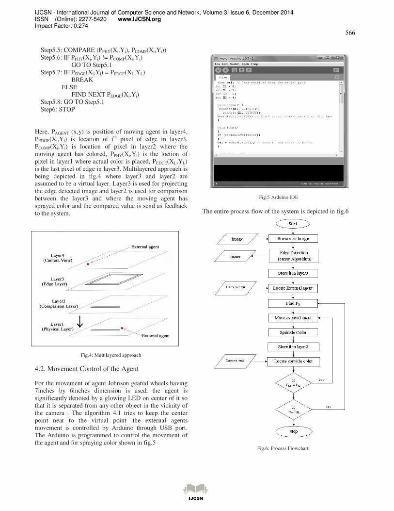
is the last pixel of edge in layer3. Multilayered approach is
being depicted in fig.4 where layer3 and layer2 are assumed to be a virtual layer. Layer3 is used for projecting
the edge detected image and layer2 is used for comparison
between the layer3 and where the moving agent has
sprayed color and the compared value is send as feedback
to the system.
Fig.4: Multilayered approach
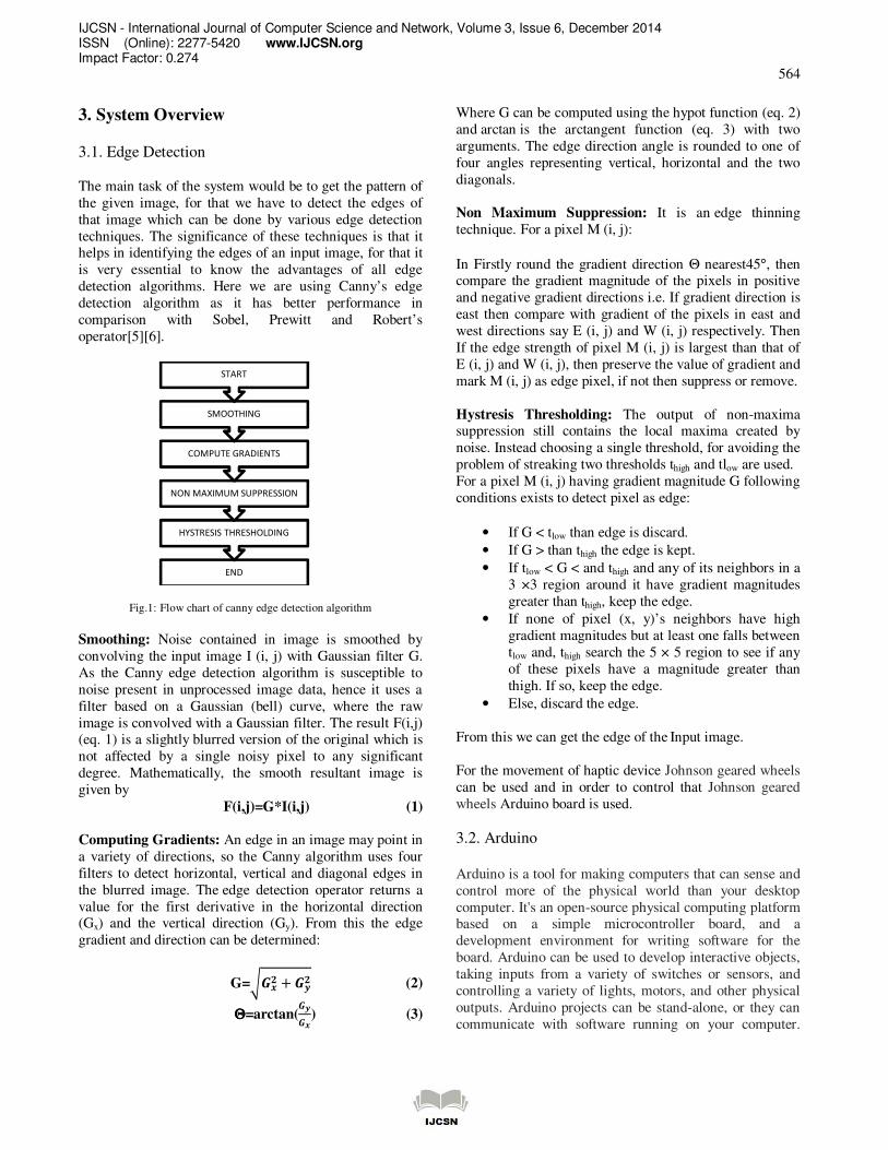
4.2. Movement Control of the Agent
For the movement of agent Johnson geared wheels having
7inches by 6inches dimension is used, the agent is
significantly denoted by a glowing LED on center of it so
that it is separated from any other object in the vicinity of
the camera . The algorithm 4.1 tries to keep the center
point near to the virtual point .the external agents
movement is controlled by Arduino through USB port.
The Arduino is programmed to control the movement of
the agent and for spraying color shown in fig.5
Fig.5 Arduino IDE
The entire process flow of the system is depicted in fig.6
Fig.6: Process Flowchart

IJCSN - International Journal of Computer Science and Network, Volume 3, Issue 6, December 2014 ISSN (Online): 2277-5420 www.IJCSN.org Impact Factor: 0.274
567
The circuit of the Arduino with the dual H-bridge for
controlling the agent is shown in fig.7
Fig.7: Arduino connection with the agent
5. Conclusion and Future Works The main focus has been given to design and fabricate a
system comprising of Arduino, moving agent, one optical
feedback system. This system is dedicated for painting
graphics on uneven surface, omitting the drawbacks of
previously developed system related to this concept and also overcome throughout involvement of humans in the
working of a system. The graphics designed by this system
is more accurate as compared to humans. As this works
doesn’t involve use of any kind of sensors, so it is cost
effective, but in the area where cost is not of primary
concerned, sensors can be deployed to increase the
functionality of this system. Here the communication
between the moving agent with the computer is
guided/wired communication ,hence it can be made
wireless in order to cover a large area and to made the
system free of wires .few instruments can be attached to increase the functionality of the system like in the field of
paleontology.
References
[1] Nicolai Beni, “Rapid Prototyping of Low Cost 1 DOF Haptic Interfaces”, in IEEE Haptics Symposium, 2014, pp. 479-483.
[2] Yuxin Jing, “ AndroRC: An Android Remote Control Car Unit for Search Missions” , in Systems, Applications and Technology Conference (LISAT), 2014 , pp. 1 – 5
[3] T. Gokyu, “Development Of Wall Painting Robot” , in 13th ISARC, 1996, pp. 949-956
[4] Luc Claesen, et.al., “Smart Camera SoC System for Interactive Real-Time Real-Brush based Digital Painting Systems” , in 18th IEEE/IFIP International Conference on VLSI and System-on-Chip (VLSI-SoC 2010), 2010,pp. 247-252.
[5] Rashmi, and Mukesh Kumar, “Algorithm and Technique on Various Edge Detection a Survey”, Signal & Image Processing: An International Journal (SIPIJ), Vol.4, No.3, June 2013, pp. 65-75
[6] G.T. Shrivakshan, and Dr.C. Chandrasekar, “ A
Comparison of various Edge Detection Techniques used in Image Processing”, IJCSI International Journal of Computer Science Issues, Vol. 9, Issue 5, No 1, September 2012, pp. 269-276.
[7] Arduino, Arduino Leonardo [Online], Available: http://arduino.cc/en/Main/ArduinoBoardLeonardo, accessed on 12th October 2014.
[8] Dual H-bridge, [Online], Available:
http://www.instructables.com/id/Arduino-Modules-L298N-Dual-H-Bridge-Motor-Controll/, accessed on 12th October 2014.
Authors
Jit Sengupta is pursuing Masters in Technology in Computer Science & Engg. Department, From National Institute of Technology, Agartala (Tripura).He has completed his Bachelor of Engineering in Computer Science and Engineering Department, From Tripura Institute of Technology, Agartala (Tripura). His field of interest is focused on digital image processing, Artificial Intelligence, Robotics and Computer Architecture. He is member of various Scientific Bodies.
Suman Deb is working as a Asst. Prof. in the Dept. of Computer Science & Engg. in NIT Agartala (Tripura). He received his M.Tech. Degree in CSE from NIT Agartala. His research is focused on Artificial Intelligence, Human Computer interaction, Computer Graphics and User Interface Design.
Ashim Saha is working as a Asst. Prof. in the Dept. of Computer Science & Engg. in NIT Agartala (Tripura). He received his M.Tech. Degree in CSE from Tripura University, Agartala and B.Tech (Gold Medalist) from NIT Agartala. His research is focused on Web Technologies, Image Processing, Database Management System.