AND PHASE FLUX LINKAGE CHARACTERISTICS OF DUAL …
12
*Corresponding author, tel: +234 – 803 – 422 – 1305 COIL- AND PHASE-FLUX-LINKAGE CHARACTERISTICS OF DUAL EXCITED PERMANENT MAGNET MACHINES EQUIPPED WITH DIFFERENT WINDING CONFIGURATIONS C. C. Awah 1,* and O. I. Okoro 2 1, 2, DEPT. OF ELECTRICAL & ELECTRONICS ENGR., MICHAEL OKPARA UNIV. OF AGRIC., UMUDIKE, ABIA STATE, NIGERIA E-mail addresses: 1 [email protected], 2 [email protected] ABSTRACT The flux-linkage characteristics of dual excited permanent magnet (PM) machines equipped with concentrated windings of single- and double-layer types is investigated in this paper. This includes precise comparison of the coil and phase flux-linkage waveforms of the machines having different stator and rotor pole topologies. It is observed that, the developed machine having double layer-wound configuration have unipolar coil flux linkage waveforms, although with a resultant bipolar phase flux-linkage waveforms on summation, while their corresponding single layer-wound counterparts are characterised by both bipolar coil and phase flux-linkage waveforms. Also, the opposite coils of the machines having single-layer windings as well as even rotor pole topology produces coil flux-linkage waveforms whose shape and magnitude are identical and same; thus, resulting to more phase harmonics unlike their counterparts that are equipped with odd rotor poles and single-layer winding configuration whose coil waveforms are shifted, thereby resulting to effective cancellation of harmonics in the resultant phase waveforms. In general, the single-layer-wound machines exhibit higher peak-to-peak and fundamental flux-linkage values than their double- layer-wound equivalents. Keywords: Dual excitation, flux-linkage, single- and double-layer windings, rotor and stator pole combinations. 1. INTRODUCTION The shape and nature of flux-linkage and back-EMF waveforms of permanent magnet (PM) machines are important determinants in the design and analysis of electric machines, since they give insight on the output electromagnetic torque as well as the required control method (s) to be applied on the machines. A comparative study in [1] shows that the single-layer wound machines have better flux-weakening capability as well as higher fault-tolerant potential than their double-layer counterparts. However, the double-layer wound machines are good candidates for shorter end windings and hence improved efficiency, better or more sinusoidal electromotive force (EMF) waveforms, lower torque ripple and lower rotor losses due to their low magneto-motive force (MMF) components. It is noted in [2], that surface-mounted permanent magnet machines (SPM) having single-layer wound topology exhibit larger inductance as well as more harmonic contents than their double-layer counterparts and this could be detrimental to the operational speed of the single-tooth wound machines. Hence, the double-layer wound machines have wider operating speed range. Thus, an enhanced flux- weakening potential is obtained in the double-layer- wound machines as mentioned in [3]. It is also proven in [3] that, the double-layer wound machines have lower core and eddy current losses relative to the single-layer-wound ones. Further reduction of losses would be obtained by adopting distributed kind of windings in place of the concentrated non-overlapping windings. It is shown in [4] that, the single-layer wound machines have higher winding factors and consequently are good candidates for larger torque- density compared to their double-layer equivalents. Li et al [5] show that the losses of fractional slot concentrated-winding PM machines reduces with increasing number of winding layers, although the lower winding-layer machines would produce higher electromagnetic output torque. In contrast, a study in [6] shows that the multi-layer wound machines are capable of producing larger torque than the single- layer ones, owing to their higher values of reluctance torque and saliency ratios. In addition, the multi-layer Nigerian Journal of Technology (NIJOTECH) Vol. 37, No. 3, July 2018, pp. 758 – 769 Copyright© Faculty of Engineering, University of Nigeria, Nsukka, Print ISSN: 0331-8443, Electronic ISSN: 2467-8821 www.nijotech.com http://dx.doi.org/10.4314/njt.v37i3.27
Transcript of AND PHASE FLUX LINKAGE CHARACTERISTICS OF DUAL …
*Corresponding author, tel: +234 – 803 – 422 – 1305
COIL- AND PHASE-FLUX-LINKAGE CHARACTERISTICS OF DUAL EXCITED
PERMANENT MAGNET MACHINES EQUIPPED WITH DIFFERENT
WINDING CONFIGURATIONS
C. C. Awah1,* and O. I. Okoro2
1, 2, DEPT. OF ELECTRICAL & ELECTRONICS ENGR., MICHAEL OKPARA UNIV. OF AGRIC., UMUDIKE, ABIA STATE, NIGERIA
E-mail addresses: [email protected], [email protected]
ABSTRACT
The flux-linkage characteristics of dual excited permanent magnet (PM) machines equipped with concentrated
windings of single- and double-layer types is investigated in this paper. This includes precise comparison of the coil
and phase flux-linkage waveforms of the machines having different stator and rotor pole topologies. It is observed
that, the developed machine having double layer-wound configuration have unipolar coil flux linkage waveforms,
although with a resultant bipolar phase flux-linkage waveforms on summation, while their corresponding single
layer-wound counterparts are characterised by both bipolar coil and phase flux-linkage waveforms. Also, the opposite
coils of the machines having single-layer windings as well as even rotor pole topology produces coil flux-linkage
waveforms whose shape and magnitude are identical and same; thus, resulting to more phase harmonics unlike their
counterparts that are equipped with odd rotor poles and single-layer winding configuration whose coil waveforms
are shifted, thereby resulting to effective cancellation of harmonics in the resultant phase waveforms. In general, the
single-layer-wound machines exhibit higher peak-to-peak and fundamental flux-linkage values than their double-
layer-wound equivalents.
Keywords: Dual excitation, flux-linkage, single- and double-layer windings, rotor and stator pole combinations.
1. INTRODUCTION
The shape and nature of flux-linkage and back-EMF
waveforms of permanent magnet (PM) machines are
important determinants in the design and analysis of
electric machines, since they give insight on the output
electromagnetic torque as well as the required control
method (s) to be applied on the machines. A
comparative study in [1] shows that the single-layer
wound machines have better flux-weakening capability
as well as higher fault-tolerant potential than their
double-layer counterparts. However, the double-layer
wound machines are good candidates for shorter end
windings and hence improved efficiency, better or
more sinusoidal electromotive force (EMF) waveforms,
lower torque ripple and lower rotor losses due to their
low magneto-motive force (MMF) components.
It is noted in [2], that surface-mounted permanent
magnet machines (SPM) having single-layer wound
topology exhibit larger inductance as well as more
harmonic contents than their double-layer
counterparts and this could be detrimental to the
operational speed of the single-tooth wound machines.
Hence, the double-layer wound machines have wider
operating speed range. Thus, an enhanced flux-
weakening potential is obtained in the double-layer-
wound machines as mentioned in [3]. It is also proven
in [3] that, the double-layer wound machines have
lower core and eddy current losses relative to the
single-layer-wound ones. Further reduction of losses
would be obtained by adopting distributed kind of
windings in place of the concentrated non-overlapping
windings. It is shown in [4] that, the single-layer wound
machines have higher winding factors and
consequently are good candidates for larger torque-
density compared to their double-layer equivalents. Li
et al [5] show that the losses of fractional slot
concentrated-winding PM machines reduces with
increasing number of winding layers, although the
lower winding-layer machines would produce higher
electromagnetic output torque. In contrast, a study in
[6] shows that the multi-layer wound machines are
capable of producing larger torque than the single-
layer ones, owing to their higher values of reluctance
torque and saliency ratios. In addition, the multi-layer
Nigerian Journal of Technology (NIJOTECH)
Vol. 37, No. 3, July 2018, pp. 758 – 769
Copyright© Faculty of Engineering, University of Nigeria, Nsukka, Print ISSN: 0331-8443, Electronic ISSN: 2467-8821
www.nijotech.com
http://dx.doi.org/10.4314/njt.v37i3.27
COIL- AND PHASE-FLUX-LINKAGE CHARACTERISTICS OF DUAL EXCITED PERMANENT MAGNET MACHINES…C. C. Awah & O.I. Okoro
Nigerian Journal of Technology Vol. 37, No. 3, July, 2018 759
wound machines have reduced torque ripple and
enhanced overload withstand capability compared to
the single-layer ones; albeit with increased mechanical
complexity.
Furthermore, [7] demonstrates that the single-layer
wound synchronous reluctance PM machines are
characterized by significant amount of radial magnetic
force on the rotor which could lead to heavy stress on
the bearings, due to the resultant unbalanced magnetic
pull. However, much reduction of these forces could be
achieved by the use of additional flux-barriers on the
rotor. It is also noted that, more sinusoidal as well as
low amplitude of stator and rotor magnetic potentials
are realized by adopting distributed windings in place
of fractional-slot concentrated windings. Moreover, an
improved analytical estimation of leakage flux and
inductances of machines having single- and double-
layer winding are proposed in [8] and [9], respectively.
This approach is fast and consumes less time than the
finite element (FEA) approach, although may not be
entirely accurate since it is based on assumptions and
approximations such as negligible magnetic saturation,
etc. Moreover, it is demonstrated in [10] that, the
torque and power density of axial flux PM machine is
inversely related to the number of its winding-layers,
i.e. the lower the number of layers the better its torque
performance. However, a little compromise is made on
the overall machine efficiency.
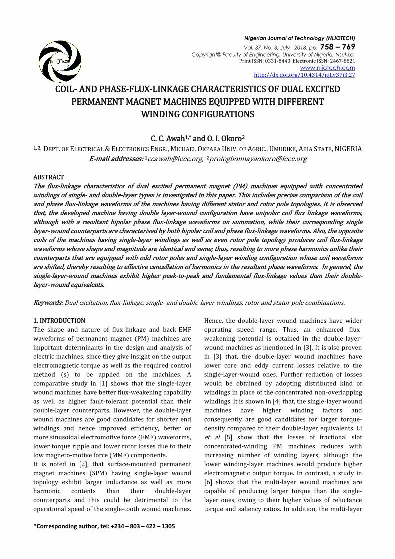
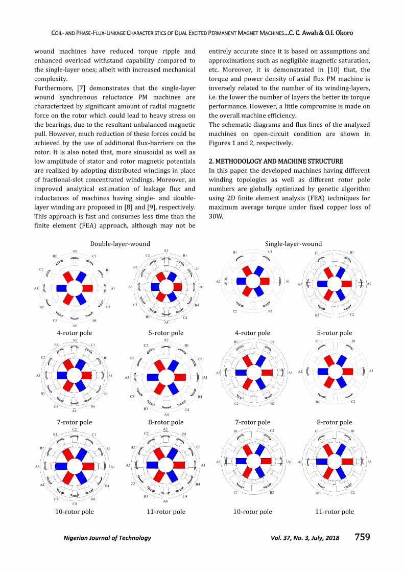
The schematic diagrams and flux-lines of the analyzed
machines on open-circuit condition are shown in
Figures 1 and 2, respectively.
2. METHODOLOGY AND MACHINE STRUCTURE
In this paper, the developed machines having different
winding topologies as well as different rotor pole
numbers are globally optimized by genetic algorithm
using 2D finite element analysis (FEA) techniques for
maximum average torque under fixed copper loss of
30W.
Double-layer-wound Single-layer-wound
4-rotor pole 5-rotor pole 4-rotor pole 5-rotor pole
7-rotor pole 8-rotor pole 7-rotor pole 8-rotor pole
10-rotor pole 11-rotor pole 10-rotor pole 11-rotor pole
COIL- AND PHASE-FLUX-LINKAGE CHARACTERISTICS OF DUAL EXCITED PERMANENT MAGNET MACHINES…C. C. Awah & O.I. Okoro
Nigerian Journal of Technology Vol. 37, No. 3, July, 2018 760
13-rotor pole 14-rotor pole 13-rotor pole 14-rotor pole
Figure 1: Schematic diagram of the developed machines with different winding configuration and pole numbers.
It is worth mentioning that, the series turns per phase
of these machines are kept same in the analysis for
fairness, the sum total being 72 turns per phase. The
FEA design model is injected with three-phase
sinusoidal current having 120deg. phase displacement,
then operated at 400rpm speed on no-load condition in
order to obtain the open-circuit flux-linkages and
consequently, the other machine performances, such as
induced electromotive force (EMF), torque etc.
Nevertheless, we restricted this study mainly to the
analysis of the flux-linkages analysis with few static
torque results. Note also, that the used PM material in
this work has a magnetic remanence of 1.2Tesla and
relative permeability of 1.05.
The injected balanced three-phase sinusoidal currents
are given by equations (1)-(3), however with Imax=0
for the considered open circuit condition in this paper.
sin( ) (1)
sin( 2
3 ) (2)
sin( 2
3 ) (3)
where Imax = the maximum input current, Nr = the
number of rotor poles, ω the rotational speed, and
initial current advance angle.
3. RESULTS
The waveforms and spectra of the coil- and phase- flux-
linkages of the analysed machines having different
rotor-pole combinations with various rotor positions
are shown in Figures 3-10. For the double-layer-wound
machines, it is worth noting that the orthogonal coils
always have different coil-flux linkage waveforms,
while the diametrically opposite coils will have the
same coil flux linkage if the number of rotor poles is
even, otherwise, i.e. when the number of rotor poles is
odd, their waveforms also differ. Similarly, for the
single-layer-wound machines, there are only the
diametrically opposite coils but no orthogonal coils in
the same phase. In general, for the same rotor pole
number, the double-layer-wound machines will have
relatively lower amplitudes, compared to the single-
layer-wound machines.
4-rotor 5-rotor 7-rotor 8-rotor
10-rotor 11-rotor 13-rotor 14-rotor
Figure 2: Open circuit flux distributions of the analysed machines.
COIL- AND PHASE-FLUX-LINKAGE CHARACTERISTICS OF DUAL EXCITED PERMANENT MAGNET MACHINES…C. C. Awah & O.I. Okoro
Nigerian Journal of Technology Vol. 37, No. 3, July, 2018 761
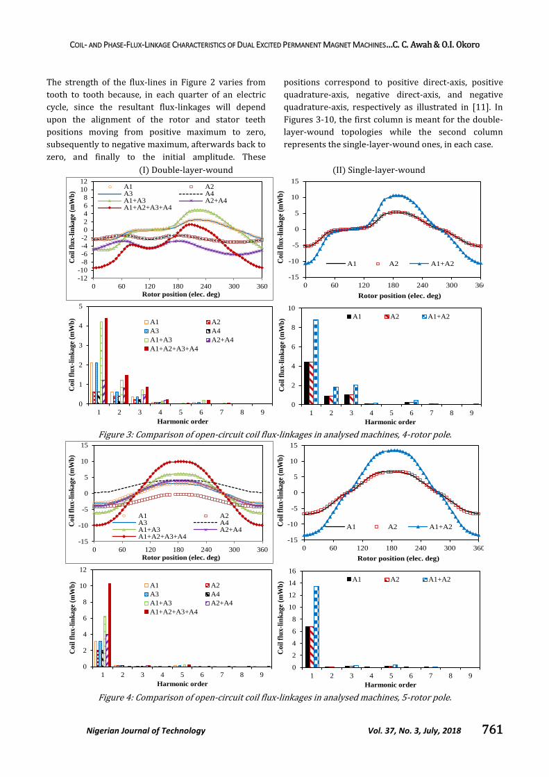
The strength of the flux-lines in Figure 2 varies from
tooth to tooth because, in each quarter of an electric
cycle, since the resultant flux-linkages will depend
upon the alignment of the rotor and stator teeth
positions moving from positive maximum to zero,
subsequently to negative maximum, afterwards back to
zero, and finally to the initial amplitude. These
positions correspond to positive direct-axis, positive
quadrature-axis, negative direct-axis, and negative
quadrature-axis, respectively as illustrated in [11]. In
Figures 3-10, the first column is meant for the double-
layer-wound topologies while the second column
represents the single-layer-wound ones, in each case.
(I) Double-layer-wound (II) Single-layer-wound
Figure 3: Comparison of open-circuit coil flux-linkages in analysed machines, 4-rotor pole.
Figure 4: Comparison of open-circuit coil flux-linkages in analysed machines, 5-rotor pole.
-12
-10
-8
-6
-4
-2
0
2
4
6
8
10
12
0 60 120 180 240 300 360
Co
il f
lux-l
ink
ag
e (m
Wb
)
Rotor position (elec. deg)
A1 A2A3 A4A1+A3 A2+A4A1+A2+A3+A4
-15
-10
-5
0
5
10
15
0 60 120 180 240 300 360C
oil
flu
x-l
ink
ag
e (m
Wb
)
Rotor position (elec. deg)
A1 A2 A1+A2
0
1
2
3
4
5
1 2 3 4 5 6 7 8 9
Co
il f
lux-l
ink
ag
e (m
Wb
)
Harmonic order
A1 A2
A3 A4
A1+A3 A2+A4
A1+A2+A3+A4
0
2
4
6
8
10
1 2 3 4 5 6 7 8 9
Co
il f
lux
-lin
ka
ge
(mW
b)
Harmonic order
A1 A2 A1+A2
-15
-10
-5
0
5
10
15
0 60 120 180 240 300 360
Co
il f
lux
-lin
ka
ge
(mW
b)
Rotor position (elec. deg)
A1 A2A3 A4A1+A3 A2+A4A1+A2+A3+A4
-15
-10
-5
0
5
10
15
0 60 120 180 240 300 360
Co
il f
lux-
lin
ka
ge
(mW
b)
Rotor position (elec. deg)
A1 A2 A1+A2
0
2
4
6
8
10
12
1 2 3 4 5 6 7 8 9
Co
il f
lux
-lin
ka
ge
(mW
b)
Harmonic order
A1 A2
A3 A4
A1+A3 A2+A4
A1+A2+A3+A4
0
2
4
6
8
10
12
14
16
1 2 3 4 5 6 7 8 9
Co
il f
lux
-lin
ka
ge
(mW
b)
Harmonic order
A1 A2 A1+A2
COIL- AND PHASE-FLUX-LINKAGE CHARACTERISTICS OF DUAL EXCITED PERMANENT MAGNET MACHINES…C. C. Awah & O.I. Okoro
Nigerian Journal of Technology Vol. 37, No. 3, July, 2018 762
It is worth noting that, the per phase coil group A1 and
A3 of the double-layer-wound machines have larger
amplitude in all the analysis than their complementary
coil group, A2 and A4. This is because the flux-linkage
waveforms of coils A2 and A4 are unipolar and in
particular, they have different polarity in the odd-rotor
pole machines, which in turn reduces the resultant flux-
linkage significantly on summation. A typical example
is seen in the 13-pole machine in which case, the sum of
A2 and A4 flux-linkages is more or less negligible due
to its unipolar waveforms with almost same amplitude
and different polarity. Hence, the entire flux
contribution in this case could be said to have been
made by coils A1 and A3 only.
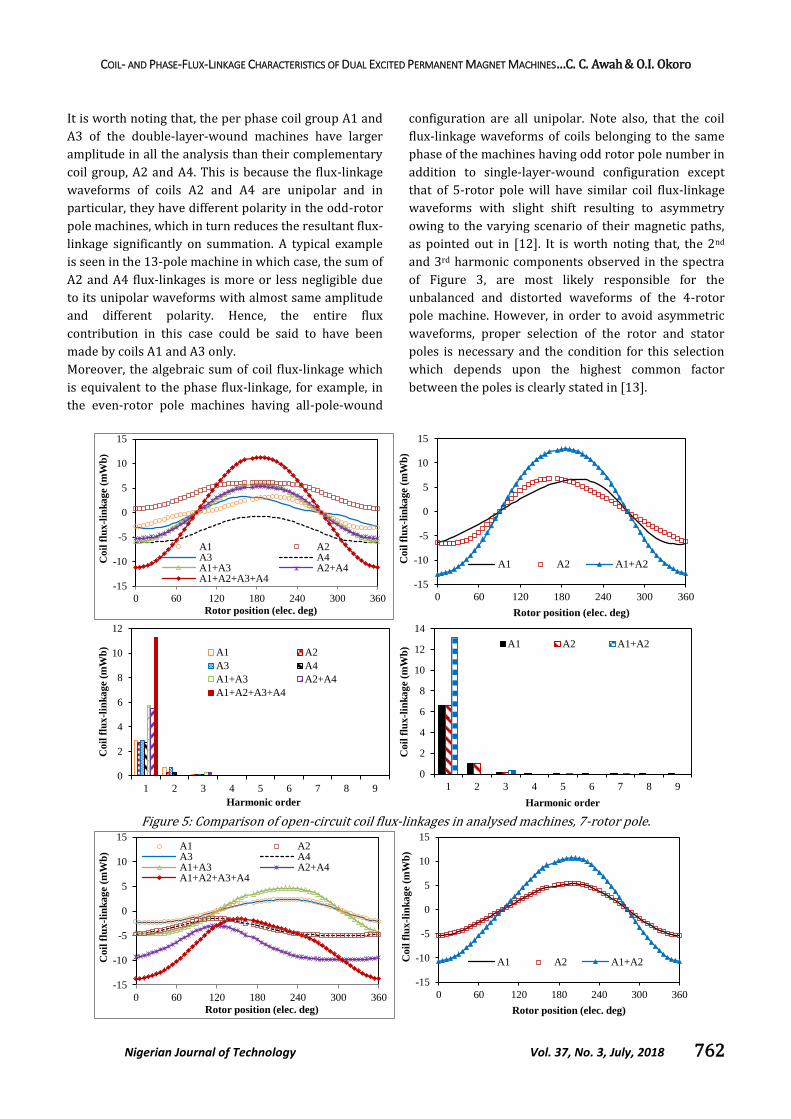
Moreover, the algebraic sum of coil flux-linkage which
is equivalent to the phase flux-linkage, for example, in
the even-rotor pole machines having all-pole-wound
configuration are all unipolar. Note also, that the coil
flux-linkage waveforms of coils belonging to the same
phase of the machines having odd rotor pole number in
addition to single-layer-wound configuration except
that of 5-rotor pole will have similar coil flux-linkage
waveforms with slight shift resulting to asymmetry
owing to the varying scenario of their magnetic paths,
as pointed out in [12]. It is worth noting that, the 2nd
and 3rd harmonic components observed in the spectra
of Figure 3, are most likely responsible for the
unbalanced and distorted waveforms of the 4-rotor
pole machine. However, in order to avoid asymmetric
waveforms, proper selection of the rotor and stator
poles is necessary and the condition for this selection
which depends upon the highest common factor
between the poles is clearly stated in [13].
Figure 5: Comparison of open-circuit coil flux-linkages in analysed machines, 7-rotor pole.
-15
-10
-5
0
5
10
15
0 60 120 180 240 300 360
Co
il f
lux
-lin
ka
ge
(mW
b)
Rotor position (elec. deg)
A1 A2A3 A4A1+A3 A2+A4A1+A2+A3+A4
-15
-10
-5
0
5
10
15
0 60 120 180 240 300 360
Co
il f
lux-l
ink
ag
e (m
Wb
)
Rotor position (elec. deg)
A1 A2 A1+A2
0
2
4
6
8
10
12
1 2 3 4 5 6 7 8 9
Co
il f
lux
-lin
ka
ge
(mW
b)
Harmonic order
A1 A2
A3 A4
A1+A3 A2+A4
A1+A2+A3+A4
0
2
4
6
8
10
12
14
1 2 3 4 5 6 7 8 9
Co
il f
lux
-lin
ka
ge
(mW
b)
Harmonic order
A1 A2 A1+A2
-15
-10
-5
0
5
10
15
0 60 120 180 240 300 360
Co
il f
lux
-lin
ka
ge
(mW
b)
Rotor position (elec. deg)
A1 A2A3 A4A1+A3 A2+A4A1+A2+A3+A4
-15
-10
-5
0
5
10
15
0 60 120 180 240 300 360
Co
il f
lux
-lin
ka
ge
(mW
b)
Rotor position (elec. deg)
A1 A2 A1+A2
COIL- AND PHASE-FLUX-LINKAGE CHARACTERISTICS OF DUAL EXCITED PERMANENT MAGNET MACHINES…C. C. Awah & O.I. Okoro
Nigerian Journal of Technology Vol. 37, No. 3, July, 2018 763
Figure 6: Comparison of open-circuit coil flux-linkages in analysed machines, 8-rotor pole.
Figure 7: Comparison of open-circuit coil flux-linkages in analysed machines, 10-rotor pole.
Figure 8: Comparison of open-circuit coil flux-linkages in analysed machines, 11-rotor pole.
0
2
4
6
8
1 2 3 4 5 6 7 8 9
Co
il f
lux
-lin
ka
ge
(mW
b)
Harmonic order
A1 A2
A3 A4
A1+A3 A2+A4
A1+A2+A3+A4
0
2
4
6
8
10
12
1 2 3 4 5 6 7 8 9
Co
il f
lux
-lin
ka
ge
(mW
b)
Harmonic order
A1 A2 A1+A2
-20
-15
-10
-5
0
5
10
15
20
0 60 120 180 240 300 360
Co
il f
lux
-lin
ka
ge
(mW
b)
Rotor position (elec. deg)
A1 A2A3 A4A1+A3 A2+A4A1+A2+A3+A4
-15
-10
-5
0
5
10
15
0 60 120 180 240 300 360
Co
il f
lux
-lin
ka
ge
(mW
b)
Rotor position (elec. deg)
A1 A2 A1+A2
0
2
4
6
8
10
1 2 3 4 5 6 7 8 9
Co
il f
lux
-lin
ka
ge
(mW
b)
Harmonic order
A1 A2
A3 A4
A1+A3 A2+A4
A1+A2+A3+A4
0
2
4
6
8
10
12
1 2 3 4 5 6 7 8 9
Co
il f
lux
-lin
ka
ge
(mW
b)
Harmonic order
A1 A2 A1+A2
-15
-10
-5
0
5
10
15
0 60 120 180 240 300 360
Coi
l flu
x-li
nk
age
(mW
b)
Rotor position (elec. deg)
A1 A2A3 A4A1+A3 A2+A4A1+A2+A3+A4 -15
-10
-5
0
5
10
15
0 60 120 180 240 300 360
Coi
l flu
x-li
nk
age
(mW
b)
Rotor position (elec. deg)
A1 A2 A1+A2
0
2
4
6
8
1 2 3 4 5 6 7 8 9
Co
il f
lux
-lin
ka
ge
(mW
b)
Harmonic order
A1 A2
A3 A4
A1+A3 A2+A4
A1+A2+A3+A4
0
2
4
6
8
10
12
1 2 3 4 5 6 7 8 9
Co
il f
lux
-lin
ka
ge
(mW
b)
Harmonic order
A1 A2 A1+A2
COIL- AND PHASE-FLUX-LINKAGE CHARACTERISTICS OF DUAL EXCITED PERMANENT MAGNET MACHINES…C. C. Awah & O.I. Okoro
Nigerian Journal of Technology Vol. 37, No. 3, July, 2018 764
Note also that, the coil flux-linkages of the even-rotor
pole machines are identical, thus its individual coil
harmonics are persistent in their respective phase
spectra. In contrary, the coil waveforms of the odd-
rotor pole machines are not identical thus they get rid-
off the harmonics in their phase spectra by their
cancellation effect on summation. More importantly, it
should be noted that, although the waveforms of coils
A2 and A4 are unipolar in the odd-rotor pole machines
having double-layer-wound topology; their overall
phase flux-linkage waveforms are bipolar. Also, it is
worth noting that, the coil flux-linkage waveforms of
A1 and A3 are bipolar in all the cases.
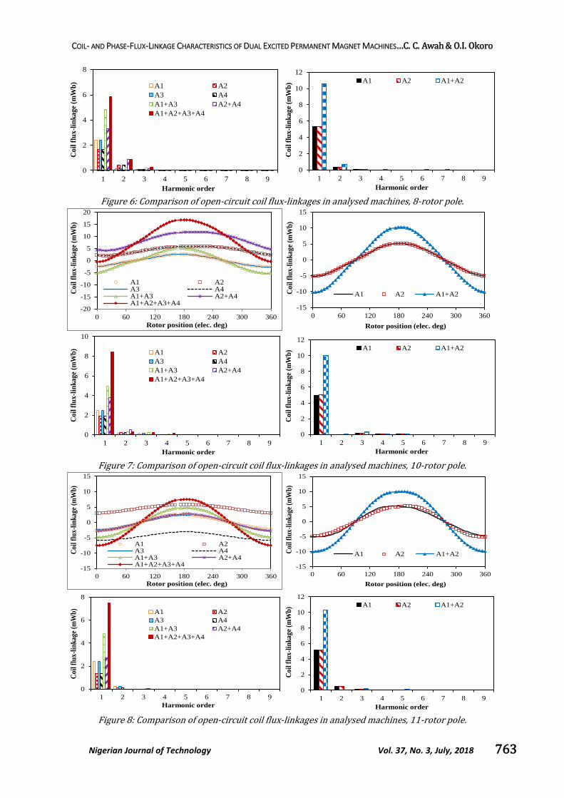
Although, not given in this paper for lack of space and
scope, the odd rotor pole machines having single-layer
windings usually have higher winding factor than their
corresponding double-layer-wound counterparts. Thus,
they have better performance than the double-layer
ones; however they suffer from high torque ripple.
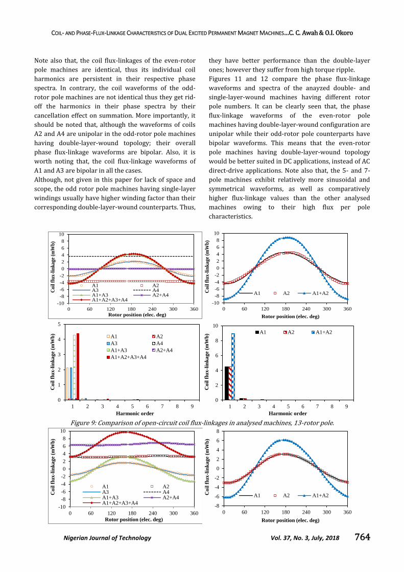
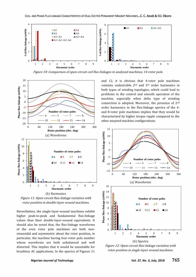
Figures 11 and 12 compare the phase flux-linkage
waveforms and spectra of the anayzed double- and
single-layer-wound machines having different rotor
pole numbers. It can be clearly seen that, the phase
flux-linkage waveforms of the even-rotor pole
machines having double-layer-wound configuration are
unipolar while their odd-rotor pole counterparts have
bipolar waveforms. This means that the even-rotor
pole machines having double-layer-wound topology
would be better suited in DC applications, instead of AC
direct-drive applications. Note also that, the 5- and 7-
pole machines exhibit relatively more sinusoidal and
symmetrical waveforms, as well as comparatively
higher flux-linkage values than the other analysed
machines owing to their high flux per pole
characteristics.
Figure 9: Comparison of open-circuit coil flux-linkages in analysed machines, 13-rotor pole.
-10
-8
-6
-4
-2
0
2
4
6
8
10
0 60 120 180 240 300 360
Co
il f
lux
-lin
ka
ge
(mW
b)
Rotor position (elec. deg)
A1 A2A3 A4A1+A3 A2+A4A1+A2+A3+A4
-10
-8
-6
-4
-2
0
2
4
6
8
10
0 60 120 180 240 300 360
Co
il f
lux
-lin
ka
ge
(mW
b)
Rotor position (elec. deg)
A1 A2 A1+A2
0
1
2
3
4
5
1 2 3 4 5 6 7 8 9
Co
il f
lux
-lin
ka
ge
(mW
b)
Harmonic order
A1 A2
A3 A4
A1+A3 A2+A4
A1+A2+A3+A4
0
2
4
6
8
10
1 2 3 4 5 6 7 8 9
Co
il f
lux
-lin
ka
ge
(mW
b)
Harmonic order
A1 A2 A1+A2
-10
-8
-6
-4
-2
0
2
4
6
8
10
0 60 120 180 240 300 360
Co
il f
lux
-lin
ka
ge
(mW
b)
Rotor position (elec. deg)
A1 A2A3 A4A1+A3 A2+A4A1+A2+A3+A4
-8
-6
-4
-2
0
2
4
6
8
0 60 120 180 240 300 360
Co
il f
lux
-lin
ka
ge
(mW
b)
Rotor position (elec. deg)
A1 A2 A1+A2
COIL- AND PHASE-FLUX-LINKAGE CHARACTERISTICS OF DUAL EXCITED PERMANENT MAGNET MACHINES…C. C. Awah & O.I. Okoro
Nigerian Journal of Technology Vol. 37, No. 3, July, 2018 765
Figure 10: Comparison of open-circuit coil flux-linkages in analysed machines, 14-rotor pole.
(a) Waveforms
(b) Harmonics
Figure 11: Open-circuit flux-linkage variation with
rotor position in double-layer wound machines.
Nevertheless, the single-layer-wound machines exhibit
higher peak-to-peak and fundamental flux-linkage
values than their double-layer-wound equivalents. It
should also be noted that, the flux-linkage waveforms
of the even rotor pole machines are both non-
sinusoidal and asymmetric about the rotor position, in
particular, the machine having four-rotor pole number
whose waveforms are both unbalanced and well
distorted. This implies that it would be unsuitable for
brushless AC applications. In the spectra of Figures 11
and 12, it is obvious that 4-rotor pole machines
contains undesirable 2nd and 3rd order harmonics in
both types of winding topologies, which could lead to
problems in the control and smooth operation of the
machine, especially when delta type of winding
connection is adopted. Moreover, the presence of 2nd
order harmonics in the flux-linkage spectra of the 4-
and 8-rotor pole machines implies that they would be
characterized by higher torque ripple compared to the
other anayzed machine configurations.
(a) Waveforms
(b) Spectra
Figure 12: Open-circuit flux-linkage variation with
rotor position in single-layer wound machines.
0
1
2
3
4
1 2 3 4 5 6 7 8 9
Co
il f
lux
-lin
ka
ge
(mW
b)
Harmonic order
A1 A2
A3 A4
A1+A3 A2+A4
A1+A2+A3+A4
0
2
4
6
8
1 2 3 4 5 6 7 8 9
Co
il f
lux
-lin
ka
ge
(mW
b)
Harmonic order
A1 A2 A1+A2
-20
-15
-10
-5
0
5
10
15
20
0 60 120 180 240 300 360
Ph
ase
flu
x-l
ink
ag
e (m
Wb
)
Rotor position (elec. deg)
4 5 7 8
10 11 13 14
Number of rotor poles
0
2
4
6
8
10
12
1 2 3 4 5 6 7 8 9
Ph
ase
flu
x-l
ink
age
(mW
b)
Harmonic order
4 5 7 8
10 11 13 14
Number of rotor poles
-15
-10
-5
0
5
10
15
0 60 120 180 240 300 360
Ph
ase
flu
x-l
ink
ag
e (m
Wb
)
Rotor position (elec. deg)
4 5 7 8
10 11 13 14
Number of rotor poles
0
2
4
6
8
10
12
14
16
1 2 3 4 5 6 7 8 9
Ph
ase
flu
x-l
ink
age (
mW
b)
Harmonic order
4 5 7 8
10 11 13 14
Number of rotor poles
COIL- AND PHASE-FLUX-LINKAGE CHARACTERISTICS OF DUAL EXCITED PERMANENT MAGNET MACHINES…C. C. Awah & O.I. Okoro
Nigerian Journal of Technology Vol. 37, No. 3, July, 2018 766
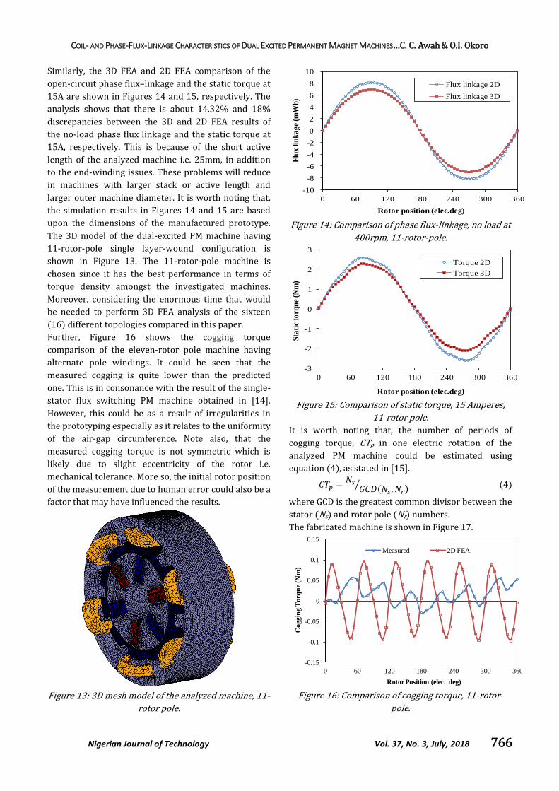
Similarly, the 3D FEA and 2D FEA comparison of the
open-circuit phase flux–linkage and the static torque at
15A are shown in Figures 14 and 15, respectively. The
analysis shows that there is about 14.32% and 18%
discrepancies between the 3D and 2D FEA results of
the no-load phase flux linkage and the static torque at
15A, respectively. This is because of the short active
length of the analyzed machine i.e. 25mm, in addition
to the end-winding issues. These problems will reduce
in machines with larger stack or active length and
larger outer machine diameter. It is worth noting that,
the simulation results in Figures 14 and 15 are based
upon the dimensions of the manufactured prototype.
The 3D model of the dual-excited PM machine having
11-rotor-pole single layer-wound configuration is
shown in Figure 13. The 11-rotor-pole machine is
chosen since it has the best performance in terms of
torque density amongst the investigated machines.
Moreover, considering the enormous time that would
be needed to perform 3D FEA analysis of the sixteen
(16) different topologies compared in this paper.
Further, Figure 16 shows the cogging torque
comparison of the eleven-rotor pole machine having
alternate pole windings. It could be seen that the
measured cogging is quite lower than the predicted
one. This is in consonance with the result of the single-
stator flux switching PM machine obtained in [14].
However, this could be as a result of irregularities in
the prototyping especially as it relates to the uniformity
of the air-gap circumference. Note also, that the
measured cogging torque is not symmetric which is
likely due to slight eccentricity of the rotor i.e.
mechanical tolerance. More so, the initial rotor position
of the measurement due to human error could also be a
factor that may have influenced the results.
Figure 13: 3D mesh model of the analyzed machine, 11-
rotor pole.
Figure 14: Comparison of phase flux-linkage, no load at
400rpm, 11-rotor-pole.
Figure 15: Comparison of static torque, 15 Amperes,
11-rotor pole.
It is worth noting that, the number of periods of
cogging torque, CTp in one electric rotation of the
analyzed PM machine could be estimated using
equation (4), as stated in [15].
( , )⁄ (4)
where GCD is the greatest common divisor between the
stator (Ns) and rotor pole (Nr) numbers.
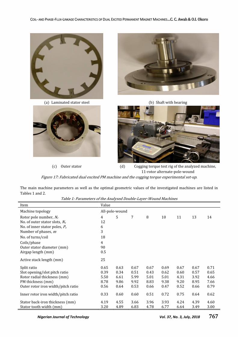
The fabricated machine is shown in Figure 17.
Figure 16: Comparison of cogging torque, 11-rotor-
pole.
-10
-8
-6
-4
-2
0
2
4
6
8
10
0 60 120 180 240 300 360
Flu
x li
nk
ag
e (m
Wb
)
Rotor position (elec.deg)
Flux linkage 2D
Flux linkage 3D
-3
-2
-1
0
1
2
3
0 60 120 180 240 300 360
Sta
tic
torq
ue
(Nm
)
Rotor position (elec.deg)
Torque 2D
Torque 3D
-0.15
-0.1
-0.05
0
0.05
0.1
0.15
0 60 120 180 240 300 360
Co
gg
ing
To
rqu
e (N
m)
Rotor Position (elec. deg)
Measured 2D FEA
COIL- AND PHASE-FLUX-LINKAGE CHARACTERISTICS OF DUAL EXCITED PERMANENT MAGNET MACHINES…C. C. Awah & O.I. Okoro
Nigerian Journal of Technology Vol. 37, No. 3, July, 2018 767
(a) Laminated stator steel (b) Shaft with bearing
(c) Outer stator (d) Cogging torque test rig of the analyzed machine,
11-rotor alternate-pole-wound
Figure 17: Fabricated dual excited PM machine and the cogging torque experimental set-up.
The main machine parameters as well as the optimal geometric values of the investigated machines are listed in
Tables 1 and 2.
Table 1: Parameters of the Analysed Double-Layer-Wound Machines
Item Value
Machine topology All-pole-wound
Rotor pole number, Nr 4 5 7 8 10 11 13 14 No. of outer stator slots, Ns 12 No. of inner stator poles, Ps 6 Number of phases, m 3
No. of turns/coil 18
Coils/phase 4 Outer stator diameter (mm) 90 Airgap length (mm) 0.5
Active stack length (mm) 25
Split ratio 0.65 0.63 0.67 0.67 0.69 0.67 0.67 0.71 Slot opening/slot pitch ratio 0.39 0.34 0.51 0.43 0.62 0.60 0.57 0.65 Rotor radial thickness (mm) 5.50 6.61 5.99 5.01 5.01 4.31 3.92 4.66 PM thickness (mm) 8.78 9.86 9.92 8.83 9.38 9.20 8.95 7.66 Outer rotor iron width/pitch ratio 0.56 0.64 0.53 0.66 0.47 0.52 0.66 0.79
Inner rotor iron width/pitch ratio 0.33 0.60 0.60 0.51 0.72 0.75 0.64 0.62
Stator back-iron thickness (mm) 4.19 4.55 3.66 3.96 3.93 4.24 4.39 4.60 Stator tooth width (mm) 3.20 4.89 6.83 4.78 6.77 6.64 3.49 3.00
COIL- AND PHASE-FLUX-LINKAGE CHARACTERISTICS OF DUAL EXCITED PERMANENT MAGNET MACHINES…C. C. Awah & O.I. Okoro
Nigerian Journal of Technology Vol. 37, No. 3, July, 2018 768
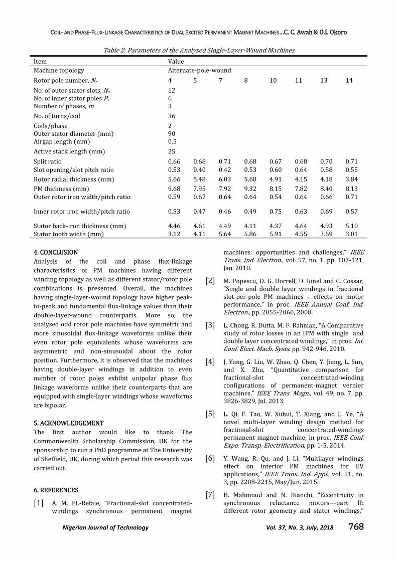
Table 2: Parameters of the Analysed Single-Layer-Wound Machines
Item Value
Machine topology Alternate-pole-wound
Rotor pole number, Nr 4 5 7 8 10 11 13 14
No. of outer stator slots, Ns 12 No. of inner stator poles Ps 6 Number of phases, m 3
No. of turns/coil 36
Coils/phase 2 Outer stator diameter (mm) 90 Airgap length (mm) 0.5
Active stack length (mm) 25
Split ratio 0.66 0.68 0.71 0.68 0.67 0.68 0.70 0.71 Slot opening/slot pitch ratio 0.53 0.40 0.42 0.53 0.60 0.64 0.58 0.55
Rotor radial thickness (mm) 5.66 5.48 6.03 5.68 4.91 4.15 4.18 3.84
PM thickness (mm) 9.68 7.95 7.92 9.32 8.15 7.82 8.40 8.13 Outer rotor iron width/pitch ratio 0.59 0.67 0.64 0.64 0.54 0.64 0.66 0.71
Inner rotor iron width/pitch ratio 0.53 0.47 0.46 0.49 0.75 0.63 0.69 0.57
Stator back-iron thickness (mm) 4.46 4.61 4.49 4.11 4.37 4.64 4.93 5.10 Stator tooth width (mm) 3.12 4.11 5.64 5.86 5.91 4.55 3.69 3.01
4. CONCLUSION
Analysis of the coil and phase flux-linkage
characteristics of PM machines having different
winding topology as well as different stator/rotor pole
combinations is presented. Overall, the machines
having single-layer-wound topology have higher peak-
to-peak and fundamental flux-linkage values than their
double-layer-wound counterparts. More so, the
analysed odd rotor pole machines have symmetric and
more sinusoidal flux-linkage waveforms unlike their
even rotor pole equivalents whose waveforms are
asymmetric and non-sinusoidal about the rotor
position. Furthermore, it is observed that the machines
having double-layer windings in addition to even
number of rotor poles exhibit unipolar phase flux
linkage waveforms unlike their counterparts that are
equipped with single-layer windings whose waveforms
are bipolar.
5. ACKNOWLEDGEMENT
The first author would like to thank The
Commonwealth Scholarship Commission, UK for the
sponsorship to run a PhD programme at The University
of Sheffield, UK, during which period this research was
carried out.
6. REFERENCES
[1] A. M. EL-Refaie, “Fractional-slot concentrated-windings synchronous permanent magnet
machines: opportunities and challenges,” IEEE Trans. Ind. Electron., vol. 57, no. 1, pp. 107-121, Jan. 2010.
[2] M. Popescu, D. G. Dorrell, D. Ionel and C. Cossar, “Single and double layer windings in fractional slot-per-pole PM machines – effects on motor performance,” in proc. IEEE Annual Conf. Ind. Electron., pp. 2055-2060, 2008.
[3] L. Chong, R. Dutta, M. F. Rahman, “A Comparative study of rotor losses in an IPM with single and double layer concentrated windings,” in proc. Int. Conf. Elect. Mach. Systs. pp. 942-946, 2010.
[4] J. Yang, G. Liu, W. Zhao, Q. Chen, Y. Jiang, L. Sun, and X. Zhu, “Quantitative comparison for fractional-slot concentrated-winding configurations of permanent-magnet vernier machines,” IEEE Trans. Magn., vol. 49, no. 7, pp. 3826-3829, Jul. 2013.
[5] L. Qi, F. Tao, W. Xuhui, T. Xiang, and L. Ye, “A novel multi-layer winding design method for fractional-slot concentrated-windings permanent magnet machine, in proc. IEEE Conf. Expo. Transp. Electrification, pp. 1-5, 2014.
[6] Y. Wang, R. Qu, and J. Li, “Multilayer windings effect on interior PM machines for EV applications,” IEEE Trans. Ind. Appl., vol. 51, no. 3, pp. 2208-2215, May/Jun. 2015.
[7] H. Mahmoud and N. Bianchi, “Eccentricity in synchronous reluctance motors—part II: different rotor geometry and stator windings,”
COIL- AND PHASE-FLUX-LINKAGE CHARACTERISTICS OF DUAL EXCITED PERMANENT MAGNET MACHINES…C. C. Awah & O.I. Okoro
Nigerian Journal of Technology Vol. 37, No. 3, July, 2018 769
IEEE Trans. Energy. Convers., vol. 30, no. 2, pp. 754-760, Jun. 2015.
[8] A. Tessarolo, “Leakage field analytical computation in semi-closed slots of unsaturated electric machines,” IEEE Trans. Energy Convers., vol. 30, no. 2, pp. 431-440, Jun. 2015.
[9] A. Tessarolo, “Analytical determination of slot leakage field and inductances of electric machines with double-layer windings and semiclosed slots,” IEEE Trans. Energy Convers., vol. 30, no. 4, pp. 1528-1536, Dec. 2015.
[10] A. Hemeida, and P. Sergeant, “Impact of single layer, double layer and four layer windings on the performance of AFPMSMs,” in proc. Int. Conf. Elect. Mach. Systs. pp. 1-6, 2016.
[11] Z.Q. Zhu and J. T. Chen, “Advanced flux-switching permanent magnet brushless machines,” IEEE Trans. Magn., vol. 46, no. 6, pp.1447-1453, Jun. 2010.
[12] W. Hua, M. Cheng, Z.Q. Zhu, and D. Howe, “Analysis and optimization of back-EMF waveform of a novel flux-switching PM motor,” IEEE Trans. Energy Convers., vol. 23, no. 3, pp. 727-733, Sep. 2008.
[13] J.T. Chen, and Z. Q. Zhu, “Winding configurations and optimal stator and rotor pole combination of flux switching PM brushless AC machines,” IEEE Trans. Energy Convers., vol. 25, no. 2, pp. 293-302, Jun. 2010.
[14] J.T. Chen, Z.Q. Zhu, S. Iwasaki, and R. P. Deodhar, “Influence of slot opening on optimal stator and rotor pole combination and electromagnetic performance of switched-flux PM brushless AC machines,” IEEE Trans. Ind. Appl., vol. 47, no. 4, pp. 1681-1691, Jul./Aug. 2011.
[15] D. Wu, J. T. Shi, Z. Q. Zhu, and X. Liu, “Electromagnetic performance of novel synchronous machines with permanent magnets in stator yoke,” IEEE Trans. Magn., vol. 50, no. 9, pp. 8102009, Sept. 2014.