Research Report 2014-10 A Novel Dual-Stator Axial-Flux ...lipo.ece.wisc.edu/2014pubs/2014-10.pdf ·...
5
Research Report University of Wisconsin-Madison College of Engineering Wisconsin Power Electronics Research Center 2559D Engineering Hall 1415 Engineering Drive Madison WI 53706-1691 © Confidential 2014-10 A Novel Dual-Stator Axial-Flux Spoke-Type Permanent Magnet Vernier Machine for Direct Drive Applications F. Zhao, T. A. Lipo*, B. Kwon Department of Electronic Systems Engineering, Hanyang University, Ansan, 426-791 Korea *Department of Electrical and Computer Engineering, University of Wisconsin-Madison, Madison, WI 53706-1691 USA
Transcript of Research Report 2014-10 A Novel Dual-Stator Axial-Flux ...lipo.ece.wisc.edu/2014pubs/2014-10.pdf ·...

Research Report
University of Wisconsin-MadisonCollege of Engineering
Wisconsin Power Electronics Research Center2559D Engineering Hall1415 Engineering DriveMadison WI 53706-1691
© Confidential
2014-10
A Novel Dual-Stator Axial-Flux Spoke-Type Permanent MagnetVernier Machine for Direct Drive Applications
F. Zhao, T. A. Lipo*, B. Kwon
Department of Electronic SystemsEngineering,
Hanyang University,Ansan, 426-791 Korea
*Department of Electrical and ComputerEngineering,
University of Wisconsin-Madison, Madison,WI 53706-1691 USA

>EA-12-1314 <
1
A Novel Dual-Stator Axial-Flux Spoke-Type Permanent Magnet Vernier Machine for Direct Drive Applications
Fei Zhao1, Student Member, IEEE, Thomas A. Lipo2, Life Fellow, IEEE, and Byung-Il Kwon1, Senior Member, IEEE
1Department of Electronic Systems Engineering, Hanyang University, Ansan, 426-791 Korea
2Department of Electrical and Computer Engineering, University of Wisconsin-Madison, Madison, WI 53706-1691 USA
This paper proposes a novel topology as a double-stator axial-flux spoke-type permanent magnet vernier machine (PMVM), which has a high torque density feature as well as a high power factor at low speed for direct-drive systems. The operation principle and basic design procedure of the proposed machine are presented and discussed. Three-dimensional finite element method (3D FEM) is utilized to analysis its magnetic field and transient output performance. Furthermore, the analytical method and a simplified two-dimensional finite element method (2D FEM) are also developed for the machine basic design and performance evaluation, which can effectively reduce the modeling and simulation time of the 3D FEM to achieve adequate accuracy.
Index Terms— Direct drive, double stator, finite element method (FEM), power factor, vernier machines.
I. INTRODUCTION
HE permanent magnet vernier machine (PMVM) has recently been recognized as a suitable alternative for low-
speed direct-drive applications such as wind turbine generators, electrical vehicles motors and others. A high-torque low-speed desirable feature is brought out by the magnetic gearing effect due to its toothed-pole structure [1], [3], [4]. In spite of their common merit of high torque density, conventional PMVMs have the limitation of low power factor which may require a high power rating of desired inverter (inverter power rating is inversely proportional to the machine power factor) [2]. Various types of double excitation or complex magnetized PM vernier machines have been investigated to further increase the torque density and utilize the limited space in the PM machine effectively [3], [4]. In particular, an analysis is carried out using a spoke array magnet with an unaligned dual-stator placement. One effective design is a dual-stator radial-flux PMVM with spoke-type PMs for both high torque density and improved power factor [3]. The spoke-type PM arrangement can increase the utilization of magnets and generate a high flux density in airgap. The dual stator design can introduce the effect of flux focusing to drive the flux to flow over dual air gaps and relatively decrease the leakage flux. This improved topology contributes to the superiority of the PM vernier machine for competing with high quality PM machines or other variable-reluctance machines in a low speed, high torque application. Moreover, research results also show that, in general, the
axial-flux PM machine topology is the best choice for the direct-drive applications due to its high torque density, high efficiency, compact construction and shape flexibility [5], [6]. Thus, a dual-stator axial-flux spoke-type PMVM (DS-AFSPMVM) incorporating all the advantages of the axial field and the dual-stator spoke-type vernier machine is presented in this article.
To clearly place the advantages of the proposed topology in
perspective, the three-dimensional finite element method (3D-FEM) is required to analyze the magnetic field and verify its competitive characteristics due to the tri-dimensional electromagnetic problem of an axial-flux machine. However, the modeling and simulation of 3D-FEM consumes much time and asks for a high demand from the calculation devices. Thus, a relatively fast and rather accurate modeling is important and necessary to be built for performance evaluation. In this paper, the analytical method and two dimensional finite element method (2D-FEM) of geometry layers in a certain radius are also carried out to verify the machine performance gradually instead of 3D-FEM especially in a repeated design process. The flux line distribution, airgap flux density distribution with various radii and the performance of torque and power factor are also given to verify the competitive high torque density and high power factor in the proposed DS-AFSPMVM.
II. TOPOLOGY OF THE PROPOSED DS-AFSPMVM
A. Configuration and Design Parameters
Configuration of the proposed DS-AFSPMVM has been investigated as in Fig.1, which has spoke-type magnets in the rotor perpendicular to the air gaps and two half-slot-pitch shifted stators. It adopts the open slot in stator and the drum winding with the coil wound around the stator yoke. This type of drum winding solves the problem of the coil fixation with the open slot, while has a similar performance with the conventional windings due to the coil-ends [7]. Windings of two stators can be connected in series as a 3-phase machine with one inverter and also can be controlled separately for various operation demands. Shifted two stators are utilized to guide the flux through the whole machine other than only half of it, and also have the skew effect to reduce the cogging torque. The main design parameters of the proposed DS-AFSPMVM are tabulated in Table I. A thick 8mm magnet is adopted in case of demagnetization. A ratio of stator slot width per slot pitch 0.63 is selected due to the optimized design of open slot in a radial-flux PMVM [8].
T
Manuscript received March 7, 2014. Corresponding author: Byung-il Kwon ([email protected]).
Digital Object Identifier inserted by IEEE
>EA-12-1314 <
2
(a)
(b)
Fig. 1. Configuration of the proposed AFPMVM. (a) Exploded view. (b) Side view.
B. Operation Principle
This principle of a vernier machine has been explained by previous authors with various expressions to produce steady torque [1], [3], [4]. While the number of stator winding poles and rotor poles is unequal, the machine still achieves smooth torque by synchronizing the space harmonics of the stator magneto-motive force (MMF) with the rotor magnet MMF. As the rotor rotates, the machine produces a rotor magnet MMF with Zr pole pairs in the airgap. The space harmonic with p pole pairs in the airgap increases greatly due to the flux modulation effect from the open stator teeth. The stator armature MMF produces the other rotating field with p pole pairs and both interact to produce the synchronous reaction torque. In addition, the slot harmonic component in vernier machine also contributes to production of a useful torque. This
(b)
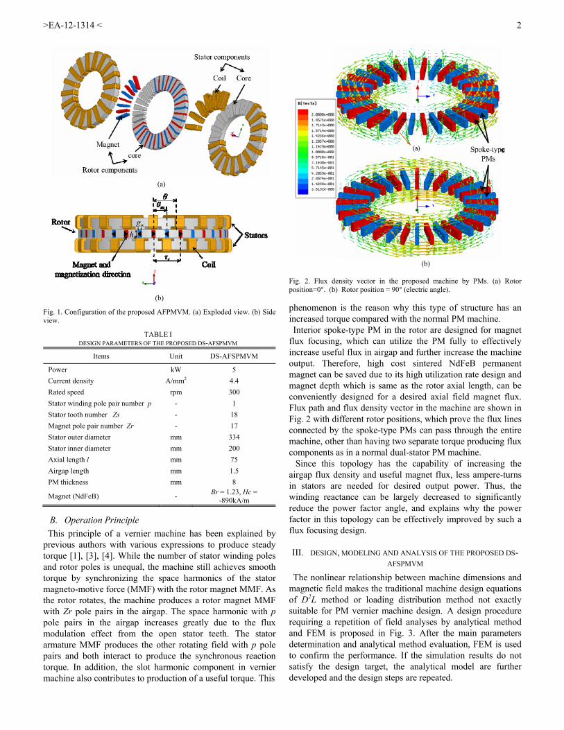
Fig. 2. Flux density vector in the proposed machine by PMs. (a) Rotor position=0°. (b) Rotor position = 90° (electric angle).
phenomenon is the reason why this type of structure has an increased torque compared with the normal PM machine. Interior spoke-type PM in the rotor are designed for magnet
flux focusing, which can utilize the PM fully to effectively increase useful flux in airgap and further increase the machine output. Therefore, high cost sintered NdFeB permanent magnet can be saved due to its high utilization rate design and magnet depth which is same as the rotor axial length, can be conveniently designed for a desired axial field magnet flux. Flux path and flux density vector in the machine are shown in Fig. 2 with different rotor positions, which prove the flux lines connected by the spoke-type PMs can pass through the entire machine, other than having two separate torque producing flux components as in a normal dual-stator PM machine. Since this topology has the capability of increasing the
airgap flux density and useful magnet flux, less ampere-turns in stators are needed for desired output power. Thus, the winding reactance can be largely decreased to significantly reduce the power factor angle, and explains why the power factor in this topology can be effectively improved by such a flux focusing design.
III. DESIGN, MODELING AND ANALYSIS OF THE PROPOSED DS-AFSPMVM
The nonlinear relationship between machine dimensions and magnetic field makes the traditional machine design equations of D2L method or loading distribution method not exactly suitable for PM vernier machine design. A design procedure requiring a repetition of field analyses by analytical method and FEM is proposed in Fig. 3. After the main parameters determination and analytical method evaluation, FEM is used to confirm the performance. If the simulation results do not satisfy the design target, the analytical model are further developed and the design steps are repeated.
TABLE I DESIGN PARAMETERS OF THE PROPOSED DS-AFSPMVM
Items Unit DS-AFSPMVM
Power kW 5
Current density A/mm2 4.4
Rated speed rpm 300
Stator winding pole pair number p - 1
Stator tooth number Zs - 18
Magnet pole pair number Zr - 17
Stator outer diameter mm 334
Stator inner diameter mm 200
Axial length l mm 75
Airgap length mm 1.5
PM thickness mm 8
Magnet (NdFeB) - Br = 1.23, Hc =
-890kA/m

>EA-12-1314 <
3
Fig. 3. Basic design procedure.
A. Analytical Method
The magnetic field of the proposed DS-AFSPMVM can be analyzed by its unit block, called an elementary domain [1]. The reference axis is selected as the center line of a slot, θm and θ are the rotor position and mechanical angle on the stator, respectively in Fig. 1 (b). The permeance coefficient P(θ) is defined as the permeance per unit area to the radial direction in the airgap and expressed as
1
0 )cos()1()(m
smj mZPPP (1)
The quantity P0 is an average air gap permeance, Pm is the amplitude value of the mth harmonic, and j is the number of slot shifts of the short pitch windings [9], [10]. Using Ampere’s law in a flux path and ignoring the MMF drop in the core to obtain the fundamental amplitude of airgap MMF Fgap(θ) is shown in (2)-(4). The relative permeability of the permanent magnet is close to 1, so the MMF Fgapm which contains permanent magnet space should also be considered as the airgap. Fm is the MMF from permanent magnet, Fgap1 and Fgap2 represent the MMF drops in two airgap and Fgap represents their average value. 021 mgapmgapgap FFFF (2)
)4
2/(0
0r
m
m
m
mrgap h
gPgBF
(3)
The square wave can be expanded in a Fourier series as
oddn
mrgapgap nZn
FF,1
))(cos(14
)(
(4)
where Br, μ0 and μm are the residual flux density, air permeability and magnet permeability, respectively. gm is the magnet thickness. hm is the rotor thickness. τr is the magnet pole pitch as shown in Fig. 1 (b). The flux density is produced by the MMF and permeance, so when only considering the major order of m = 0, 1 and n = 1 components, the no load flux density due to PM in the airgap BPM is expressed as below with a frequency of p=1
))(cos(4
)()()( 0 mrgapgapPM ZPFPFB
harmrsrgapj BZZZPF ))cos((
2)1( 1
(5)
where Bhar is the harmonic component. The back-EMF e(t), considering only the low order components of flux, is
dBqd
lND
dt
dte
q
k
kp
k
PMg
1
0
/
)()(
)(
)cos()2
)1(( 10 pZ
p
BZBlNDk mr
PMrjPMgs (6)
where λ is the phase flux linkage, N is the number of turns per phase, Dg is airgap diameter, ω is mechanical velocity, q is the slot per pole per phase, α is the slot span (2π/Zs) and the ks is the winding factor. Also l is the axial length of machine. Analytical results in this section only contain the fundamental and 1st order components for simplification.
B. Two-dimensional FEM
Since the 3D time-stepping FEM normally takes a long simulation time and requires more calculation resources, a 2D FEM approximation based on a 2D at a certain radius is preferred for performance evaluation by reducing complexity in the modeling and appreciably decreasing computation time and resources [6]. However, different than the radial-flux geometry, the axial-flux machine has a naturally difficult tri-dimensional electromagnetic geometry to model in two dimensions. A description of the approach taken to modeling the DS-AFSPMVM in 2D is provided. A half of the proposed model with single-layer in the middle radius as 133.5 mm is modeled in Ansoft's Maxwell as in Fig. 4 with the flux line distribution corresponding to one stator winding pole.
Fig. 4. Flux line path in half a 2D plane of the proposed DS-AFSPMVM in the middle radius.
Since the rotor in this 2D model should return to the other
edge periodically, it is different than the model of a normal linear machine and the master/slave boundary conditions are required. Thus, this half machine can be considered as a small portion of a radial-flux machine with a very large radius (on the order of 107 mm). The output parameters by this modeling can easily be converted from the large radial-flux machine to that of the smaller model. Table II compares the simulation time consumption of all the three methods, not including the modeling and setup time, which shows that the analytical method uses much less time but accurate modeling is complex. A 2D FEM also uses a short time but the accuracy is not high especially using a single layer simulation.
TABLE II SIMULATION TIME CONSUMPTION COMPARISON
Items Unit DS-AFSPMVM
Simulation time consumption
(electric angle 180˚)
3D FEM hr 4-5
2D FEM min 5-10
Analytical sec 1-2

>EA-12-1314 <
4
C. Performance of the Proposed Model
Fig. 5. Comparison of Back-EMF waveforms without load.
Fig. 6. Airgap flux density distribution.
Fig. 7. Variations of torque and power factor versus load angle.
In Fig. 5, back-EMF waveforms are plotted by 2D FEM, 3D
FEM and analytical methods, respectively. It can be stated that analytical method has a good agreement in the rms value with the 3D FEM simulation, while 2D FEM of single layer can be used for rough performance evaluation with a 5% error with 3D FEM result. By using the tooth modulation effect, the spoke arranged PM provides a high flux density but with huge harmonics in one airgap as in Fig. 6, which shows the airgap flux density distribution in an open-circuit field versus radius and electric angle under a winding pole. Fig. 7 shows the torque and power factor variations with load angle β, which is defined as the angle between phase current and back-EMF produced by the magnets. The maximum torque is obtained at load angle of 25 degrees, where the power factor achieves 0.87. Table III shows that the proposed DS-AFSPMVM has a high torque-to-effective volume ratio 37.7 Nm/l (27.9 Nm/l in a double-stator AFPM [11]) and a good power factor more than 0.87 (compared to just over 0.5 in a vernier hybrid machine [12]) at rated 300 rpm with an efficiency of 94.3% (includes copper loss and core loss), which demonstrates that it can effectively eliminate the essential drawback in a PMVM of low power factor.
IV. CONCLUSION
A novel DS-AFSPMVM is a good high torque density and power factor at a low speed has been proposed and should be regarded as a promising alternative for direct-drive applications such as wind turbine generators, electrical vehicles motors, cooling tower motors and so on. In addition, methodologies with short modeling and simulation time such as analytical and 2D FEM have also been presented in this paper for the basic design and no-load performance evaluation of a vernier machine indicating relatively adequate accuracy. Those methods with modification would be also valid for the design of other electric machines especially those with complex magnetic field. As a future prospect, the machine optimization and the loaded magnetic field analysis would be continued for a complete design and modeling.
ACKNOWLEDGMENT
This research was supported by BK21PLUS program through the National Research Foundation of Korea funded by the Ministry of Education.
REFERENCES [1] A. Toba and T. A. Lipo, “Generic torque-maximizing design
methodology of surface permanent–magnet vernier machine,” IEEE Trans. Indust. Applicat., vol. 36, no. 6, pp. 1539-1546, Nov. /Dec. 2000.
[2] M. R. Harris, G. H. Pajooman, and S. M. Abu Sharkh, “The problem of power factor in VRPM (transverse-flux) machines,” in Proc. IEEE ICEMD’97, No. 444, pp. 386-390, Sep. 1997.
[3] S. Niu, S.L. Ho, W.N. Fu and L.L. Wang, "Quantitative comparison of novel vernier permanent magnet machines," IEEE Trans. Magn., vol. 46, no. 6, pp. 2032-2035, Jun. 2010.
[4] F. Zhao, T. A. Lipo and B. I. Kwon, “Magnet flux focusing design of double stator permanent magnet vernier machine,” in Proc. COMPUMAG, Budapest, Hungary, July 2013.
[5] M. Lin, H. Li, X. L, X. Zhao and Z. Q. Zhu, “A novel axial field flux-switching permanent magnet wind power generator,” IEEE Trans. Magn., vol. 47, no. 10, pp. 4457-4460, Oct. 2011.
[6] C. Bianchini, F. Immovilli, E. Lorenzani, A. Bellini and L. Filici, “Axial flux permanent magnet machine design and optimization using multi-layer 2-D simulation,” in Proc. IECON, Vienna, Austria, pp. 2620-2625, 2013.
[7] A. Toba and T. A. Lipo, “Novel dual-excitation permanent magnet vernier machine,” in Proc. IEEE/IAS 34th Annual Meeting Industry Application Conf., pp. 2539-2544, 1999.
[8] F. Zhao, T. A. Lipo and B. I. Kwon, “Optimum design for a double excitation Spoke-array permanent magnet vernier machine by tooth modification,” KIEE Annual Summer Conf., Jeju, July 2013.
[9] Z. Q. Zhu, D. Howe, “Instantaneous magnetic field distribution in brushless permanent magnet DC motors. III. Effect of stator slotting,” IEEE Trans. Magn., 29(1): 143-151, 1993.
[10] T. A. Lipo, Introduction to AC machine design, (book) University of Wisconsin-WEMPEC, 3rd ed., 2007, pp. 95-101.
[11] Kano, Y., et al. “Torque-maximizing design of double-stator, axial-flux, PM machines using simple non-linear magnetic analysis,” in Proc. IEEE/IAS 42th Annual Meeting Industry Application Conf., pp. 875-881, Sep. 2007.
[12] E. Spooner and L. Haydock, “Vernier hybrid machines,” Inst. Electr. Eng. Proc. B—Electr. Power Appl., vol. 150, no. 6, pp. 655–662, Nov.2003.
TABLE III PERFORMANCE OF THE PROPOSED DS-AFSPMVM BY 3D FEM
Items DS-AFSPMVM Items DS-AFSPMVM
Max. torque 160.8 Nm Power factor 0.87
Torque density 37.7 Nm/litre Efficiency 94.3%