Analytical Calculation of Helicopter Main Rotor Blade ... Calculation of Helicopter Main Rotor Blade...
24
Analytical Calculation of Helicopter Main Rotor Blade Flight Loads in Hover and Forward Flight by Ki C. Kim ARL-TR-3180 April 2004 Approved for public release; distribution is unlimited.
-
Upload
truongkiet -
Category
Documents
-
view
232 -
download
4
Transcript of Analytical Calculation of Helicopter Main Rotor Blade ... Calculation of Helicopter Main Rotor Blade...
Analytical Calculation of Helicopter Main Rotor Blade
Flight Loads in Hover and Forward Flight
by Ki C. Kim
ARL-TR-3180 April 2004 Approved for public release; distribution is unlimited.
NOTICES
Disclaimers The findings in this report are not to be construed as an official Department of the Army position unless so designated by other authorized documents. Citation of manufacturer’s or trade names does not constitute an official endorsement or approval of the use thereof. Destroy this report when it is no longer needed. Do not return it to the originator.
Army Research Laboratory Aberdeen Proving Ground, MD 21005-5068
ARL-TR-3180 April 2004
Analytical Calculation of Helicopter Main Rotor Blade Flight Loads in Hover and Forward Flight
Ki C. Kim
Survivability/Lethality Analysis Directorate, ARL Approved for public release; distribution is unlimited.
ii
REPORT DOCUMENTATION PAGE Form Approved OMB No. 0704-0188
Public reporting burden for this collection of information is estimated to average 1 hour per response, including the time for reviewing instructions, searching existing data sources, gathering and maintaining the data needed, and completing and reviewing the collection information. Send comments regarding this burden estimate or any other aspect of this collection of information, including suggestions for reducing the burden, to Department of Defense, Washington Headquarters Services, Directorate for Information Operations and Reports (0704-0188), 1215 Jefferson Davis Highway, Suite 1204, Arlington, VA 22202-4302. Respondents should be aware that notwithstanding any other provision of law, no person shall be subject to any penalty for failing to comply with a collection of information if it does not display a currently valid OMB control number. PLEASE DO NOT RETURN YOUR FORM TO THE ABOVE ADDRESS. 1. REPORT DATE (DD-MM-YYYY)
April 2004 2. REPORT TYPE
Final 3. DATES COVERED (From - To)
January 2002–July 2002 5a. CONTRACT NUMBER
5b. GRANT NUMBER
4. TITLE AND SUBTITLE
Analytical Calculation of Helicopter Main Rotor Blade Flight Loads in Hover and Forward Flight 5c. PROGRAM ELEMENT NUMBER
5d. PROJECT NUMBER
1L162618AH80 5e. TASK NUMBER
6. AUTHOR(S)
Ki C. Kim
5f. WORK UNIT NUMBER
7. PERFORMING ORGANIZATION NAME(S) AND ADDRESS(ES)
U.S. Army Research Laboratory AMSRD-ARL-SL-BD Aberdeen Proving Ground, MD 21005-5068
8. PERFORMING ORGANIZATION REPORT NUMBER
ARL-TR-3180
10. SPONSOR/MONITOR'S ACRONYM(S)
9. SPONSORING/MONITORING AGENCY NAME(S) AND ADDRESS(ES)
11. SPONSOR/MONITOR'S REPORT NUMBER(S)
12. DISTRIBUTION/AVAILABILITY STATEMENT
Approved for public release; distribution is unlimited.
13. SUPPLEMENTARY NOTES
14. ABSTRACT
An aeroelastic analysis was conducted to calculate flight loads on the OH-58D Kiowa Warrior main rotor blade at hover and forward flight conditions. Centrifugal force and flap and chord bending moments were calculated with the University of Maryland Advanced Rotorcraft Code (UMARC) comprehensive helicopter aeroelastic analysis code. The calculated loads were correlated with available flight data for the Bell model 406LM helicopter (model 406T rotor blade) to validate the analytical model. After the correlation study, UMARC was used to calculate blade loads at the ballistic test section radial stations. These baseline loads were represented during the ballistic tests. This report presents the methods and results of the aeroelastic analysis.
15. SUBJECT TERMS
flight loads, aeroelastic analysis, dynamic response
16. SECURITY CLASSIFICATION OF: 19a. NAME OF RESPONSIBLE PERSON Ki C. Kim
a. REPORT UNCLASSIFIED
b. ABSTRACT UNCLASSIFIED
c. THIS PAGE UNCLASSIFIED
17. LIMITATION OF ABSTRACT
UL
18. NUMBER OF PAGES
26 19b. TELEPHONE NUMBER (Include area code)
(410) 278-2467 Standard Form 298 (Rev. 8/98) Prescribed by ANSI Std. Z39.18
iii
Contents
List of Figures iv
List of Tables iv
1. Introduction 1
2. Helicopter Aeroelastic Model 1 2.1 UMARC Helicopter Aeroelastic Analysis Code.............................................................2
2.2 Vehicle Trim....................................................................................................................3
2.3 Rotor Steady Response....................................................................................................3
2.4 Rotor Wake Modeling.....................................................................................................4
2.5 Solution Procedure for Blade Load Calculations ............................................................4
3. Results and Discussion 5 3.1 Correlation Study ............................................................................................................7
3.2 Blade Flight Load Calculations for Hover and 100-kn Forward Speed........................10
4. Summary 12
5. References 13
List of Abbreviations and Symbols 14
Distribution List 15
iv
List of Figures
Figure 1. Local and global degrees of freedom of KW main rotor blade. ......................................6 Figure 2. Correlation of main rotor blade natural frequencies........................................................7 Figure 3. Correlation of CFs along the blade span. ........................................................................8 Figure 4. Correlation of flap bending moment along blade span (µ = 0.28). .................................9 Figure 5. Correlation of lag bending moments along blade span (µ = 0.28). ...............................10 Figure 6. Correlation of torsional moments along blade span (µ = 0.28).....................................11
List of Tables
Table 1. Aerodynamic characteristics of KW helicopter................................................................5 Table 2. FE beam model input for OH-58D KW main rotor blade. ...............................................5 Table 3. Flap bending moments of Bell model 406T helicopter main rotor blade.........................9 Table 4. Reference blade loads and moments for test phase I-B. .................................................11
1
1. Introduction
In support of Kiowa Warrior (KW) main rotor blade ballistic vulnerability tests under the Live Fire Test and Evaluation program (1), a comprehensive helicopter aeroelastic analysis was conducted to calculate flight loads on the OH-58D KW main rotor blade at hover and forward flight conditions. Centrifugal force (CF) and flap and chord bending moments were calculated with the University of Maryland Advanced Rotorcraft Code (UMARC) comprehensive helicopter aeroelastic analysis code (2).
The calculated loads were first correlated with available flight data for the Bell Model 406LM helicopter to validate the analytical model. After the correlation study, UMARC was used to calculate blade loads at the ballistic test section radial stations. These baseline loads were represented during the ballistic tests (1).
The UMARC helicopter aeroelastic model used in the present study is a nonlinear representation of elastic rotor blades coupled to a rigid fuselage. The key feature in UMARC is the use of a finite element (FE) methodology, which can accurately model the kinematics and elastic behavior of the rotating blade. The rotor blade is assumed to be an elastic beam undergoing flap bending, lag bending, elastic twist, and axial deflections. The helicopter fuselage is assumed to be a rigid body undergoing six degrees of freedom. Each blade is modeled as a number of beam FEs. The formulation for the blade and fuselage equations of motion is based on Hamilton’s energy principle. The analysis is developed for helicopters with nonuniform rotor blades having pretwist, precone, and chord-wise offsets of the center of mass, aerodynamic center, and tension center, from the elastic axis.
This report presents the methods and results of the aeroelastic analysis. Definitions of symbols used in the report are given in the List of Abbreviations and Symbols. In section 2, the formulation details and aerodynamic model used in UMARC helicopter aeroelastic analysis code are presented. Numerical results are shown and compared with available flight data in section 3. The summary and recommendations for future work are presented in section 4.
2. Helicopter Aeroelastic Model
The calculation of rotor loads is a difficult task because of the complex interactions of structural, inertial, and aerodynamic forces acting on the rotary wing. Basically, it is necessary to calculate the periodic aerodynamic and inertial forces of the blade, and thus the resulting motion of structural components. Since the higher harmonic blade loading is the principal source of high loads, an accurate analysis of the rotor aerodynamics is required, including the effects of the

2
rotor wake, stall, and compressibility. The high frequencies involved and the importance of resonance excitation also require good inertial and structural models.
2.1 UMARC Helicopter Aeroelastic Analysis Code
The UMARC helicopter aeroelastic model used in this study is a nonlinear representation of elastic rotor blades coupled to a rigid helicopter fuselage. The key feature in UMARC is the use of an FE methodology, which can accurately model the kinematics and elastic behavior of the rotating blade. The rotor blade is assumed to be an elastic beam undergoing flap bending, lag bending, elastic twist, and axial deflections. The helicopter fuselage is assumed to be a rigid body undergoing six degrees of freedom. Each blade is modeled as a number of beam FEs. The formulation for the blade and fuselage equations of motion is based on Hamilton's energy principle. The analysis is developed for helicopters with nonuniform rotor blades having pretwist, precone, and chord-wise offsets of the center of mass, aerodynamic center, and tension center from the elastic axis. This code is the current state-of-the-art rotorcraft engineering analysis code and is widely used by U.S. Army Research Laboratory researchers and other Government/industry researchers (e.g., NASA Ames and Boeing and Sikorsky).
In UMARC, aerodynamic loads acting on the rotor blade are calculated using quasi-steady strip aerodynamic theory. Noncirculatory aerodynamic forces are also included. To include the effect of high angle-of-attack flows on the retreating blade, a dynamic stall model is incorporated. Dynamic stall characterizes the delay in flow separation because of unsteady angle of attack and the shedding of a vortex from the leading edge of the airfoil when it gets into a deep stall condition. These effects are introduced in the calculation of section lift and drag and pitching moment. The first step to calculate blade loads and moment is to determine the trim state of the helicopter for given flight conditions (i.e., gross weight, ambient conditions, and forward speed). The UMARC utilizes the coupled trim solution procedure to calculate the helicopter trim in hover and forward flight.
The coupled trim analysis consists of two phases, vehicle trim and steady response, calculated as one coupled solution using a modified Newton’s method. For a given flight condition, the control settings and the blade steady response must satisfy both the blade and the vehicle equilibrium conditions. The method of solving simultaneously the blade responses and the trim control settings is referred to as the coupled trim analysis. An uncoupled trim solution based on the rigid flapping blade assumption is used as an initial estimate for the coupled trim analysis. With the trim control settings, the blade steady responses are calculated. Using the blade responses, the rotor hub loads and a new vehicle equilibrium position are recomputed. The control settings are then updated based on the new equilibrium condition (3).
3
2.2 Vehicle Trim
Propulsive trim, which simulates an aircraft free-flight condition, is used to calculate the initial rotor control settings. The solution is determined from the overall equilibrium—three force (vertical, longitudinal, and lateral) and three moment (pitch, roll, and yaw) equations. (See Kim [4] for more details.)
For a specified helicopter weight coefficient, Cw, and a forward speed, µ, the unknown quantities to be determined from the vehicle equilibrium equations are as follows:
[ ]tailscssTu θθθθφα ,,,,, 1175.= . (1)
These values are recalculated iteratively using the modified hub forces and moments, including the blade elastic responses. The solution technique is based on a modified Newton’s method. The rotor controls, which are updated at the ith iteration, can be expressed in a canonical form as follows:
iii uuu ∆+≅+1 , (2)
in which
)(|0 iuui uF
uFu =∂∂
−=∆ , (3)
where uo is the trim control settings obtained initially using the rigid flapping blade solution and
the Jacobian uF∂∂ is calculated using the finite difference approach. For computational
efficiency, the Jacobian is computed only once initially and used for subsequent iterations.
2.3 Rotor Steady Response
The rotor dynamic response involves the determination of time-dependent blade positions at different azimuth locations for one rotor revolution. To reduce computational time, the FE equations are transformed into modal space as a few normal mode equations using the coupled natural vibration characteristics of the blade. These nonlinear periodic coupled equations are solved for steady response using an FE in time procedure based on Hamilton’s principle in weak form.
One rotor revolution is divided into a number of azimuthal (time) elements, and then periodicity of response is used to join the motions of the first and last elements. The assembly of elements results in nonlinear algebraic equations that are solved using the Newton-Raphson procedure.
After the blade response is obtained, hub forces and moments are calculated using the force summation method. These values are finally used to recalculate the coupled trim control values, as described in section 2.2.
4
2.4 Rotor Wake Modeling
For the induced in-flow distribution on the rotor disk, a free-wake model is fully coupled in the rotor aeroelastic analysis. The model can account for wake self-distortion by updating its geometry according to newly calculated in-flow and blade circulation distributions. The geometry of the free wake is divided into the following three regions: (1) near wake, (2) rolling up wake, and (3) far wake. The near wake consists of a series of radial panels, each with linear circulation distributions. The rolling-up wake consists of an inboard linear circulation distribution panel, and a tip panel that represents the rolling up of the tip vortex. The far wake is modeled as one panel with a linear circulation distribution and a concentrated tip vortex whose strength is proportional to the maximum circulation value on the rotor blade. The helical geometry of the concentrated tip vortex is updated, while the inboard wake portions are not changed.
The free-wake analysis is implemented in three stages. First, blade motion and loading are calculated using a linear in-flow model. Next, wake-induced coefficients are calculated for undistorted wake geometry. The nonuniform inflow is calculated and used to obtain blade motion and loading. Finally, the free-wake geometry is calculated. For this, the influence coefficients are reevaluated, and blade motion and loading are again obtained using nonuniform in-flow values. For subsequent iterations, the free-wake geometry is generally held fixed, and only the strength of vortices is updated. This comprehensive rotor wake model is used in the present blade flight loads calculation.
2.5 Solution Procedure for Blade Load Calculations
The following procedures were used to calculate blade loads and moments on selected blade stations in hover and forward flight conditions.
1. With prescribed input data, vehicle trim equations are calculated using rigid blade flapping (a starting point).
2. Using control inputs from the vehicle trim solution of step 1, the blade nonlinear steady response is calculated. The results give detailed individual blade responses at different span-wise and azimuthal positions.
3. Hub loads and moments are calculated using elastic rotor responses. Then, the vehicle trim values and blade responses are recalculated iteratively using the modified hub forces and moments. This step is repeated until a converged solution is obtained.
4. Blade loads and moments at selected blade stations are calculated using the force summation method.

5
3. Results and Discussion
Numerical results are first calculated for the OH-58D KW helicopter at the gross weight of 4500 lb with the forward speed of 120 kn (equivalent advance ratio, µ, of 0.28). This flight condition is selected for the benchmark correlation with the available test data obtained on the Bell Model 406T rotor blade (5, 6). The 406T rotor blade is also used on the OH-58D KW. Following the correlation, blade loads were calculated for the KW at a gross weight of 4086 lb for hover and a cruising forward speed of 100 kn (µ = 0.23).
The KW helicopter is equipped with a four-bladed, soft in-plane, advanced geometry, hingeless main rotor system. Some important aerodynamic characteristics of this helicopter rotor are given in table 1. In the present study, an effort was made to model the helicopter main rotor blade characteristics as accurately as possible. The rotor blade structural properties data obtained from manufacture (7, 8) were used to create a finite element model (FEM) (see table 2). Figure 1 shows the global and local degrees of freedom of the FE blade model for the whole rotor blade. Nonlinear twist distribution of the blade was also modeled in the blade FEs.
Table 1. Aerodynamic characteristics of KW helicopter.
Air Density, ρ
(slug/ft3)
No. of Blades
in Main Rotor,
Nb
Helicopter Gross
Weight(s), W
(lb)
Main Rotor Blade
Radius, R
(ft)
Blade Tip
Speed, ΩR
(ft/s)
Blade Mean
Chord, cm (ft)
Main Rotor
Solidity Ratio, σ
Blade Twist, θtw
(degree)
Rotor Shaft Tilt, αs
(degree)a
Blade Precone,
βp (degree)
Rotor Disk Area,
A (ft2)
.002378(ρSL) 4 4500, 4086 17.5 723.88 0.786 0.057 –12 5 2 962 a Positive for forward tilt.
Table 2. FE beam model input for OH-58D KW main rotor blade.
Element No.
Flap-Wise Bending Stiffness
Ω 42 RmEI
o
Y
Lag-Wise Bending Stiffness
Ω 42 RmEI
o
z
Torsional Stiffness
Ω 42 RmGJ
o
Element Length
Rli
1(tip) 0.00581 0.02316 0.00522 0.025 2 0.00623 0.04324 0.00634 0.106 3 0.00934 0.06237 0.00935 0.169 4 0.00823 0.05762 0.00843 0.100 5 0.01420 0.08321 0.01743 0.152 6 0.02342 0.16342 0.02654 0.162 7 0.03429 0.32143 0.03021 0.086
8 (root) 0.22840 0.72342 0.06443 0.084

6
For the calculation of blade dynamic response, each rotor blade is discretized into eight beam elements, and each beam element consists of 15 nodal degrees of freedom (see figure 1). For normal mode reduction, five coupled rotating natural modes comprised of two flaps, two lags, and one torsion mode are used. For periodic response, one cycle of time is discretized into eight time elements, and each time element represents a fifth-order polynomial distribution of motion.
Figure 1. Local and global degrees of freedom of KW main rotor blade.
Figure 2 shows the correlation of the blade rotating natural frequencies. The UMARC calculated values are compared with the experimental data (7) obtained on the Bell 406 helicopter rotor blade. The UMARC results are calculated with the nominal operating rotational value of 395 rpm. There is a good correlation between the analytical UMARC results and the experimental data, especially for the lower modes. It is also seen that UMARC slightly underpredicts the torsional frequency.

7
Figure 2. Correlation of main rotor blade natural frequencies.
3.1 Correlation Study
To validate the current blade load analysis, the calculated blade centrifugal loads and bending moments were compared with available flight test data. The correlation study will not only serve as an analysis check, but also as a guideline for further UMARC model improvement efforts.
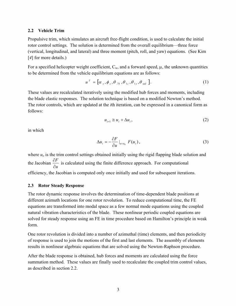
Figure 3 shows the correlation of the centrifugal force acting on the blade stations. The UMARC calculated values are compared with the flight test data obtained on the Bell 406 helicopter. The centrifugal forces measured during the flight test are available at the two blade stations— 26,600 lb at inboard blade station 24.25 (r/R = 0.116) (5) and 20,600 lb at outboard blade station 96 (r/R = 0.457) (6). Comparing the UMARC results obtained using nonuniform FE beam model with the flight test data, we observe an excellent correlation. Also shown in the figure is the analytical result obtained with a simple uniform blade assumption. As expected, the result obtained using the uniform blade shows a poor correlation. This is most likely due to the high nonuniformity of the helicopter blade; rotor analysis with a simple uniform blade model can generate erroneous results.
Blad
eN
atur
alFr
eque
ncy
(per
rev.
)
0
1
2
3
4
5
6
7
Model 406 Experimental Data
UMARC Code Prediction
FirstLag
First Flap SecondFlap
SecondLag
Torsion
Correlation of Rotor Blade Natural FrequenciesΩ = 395 r.p.m.
8
Figure 3. Correlation of CFs along the blade span.
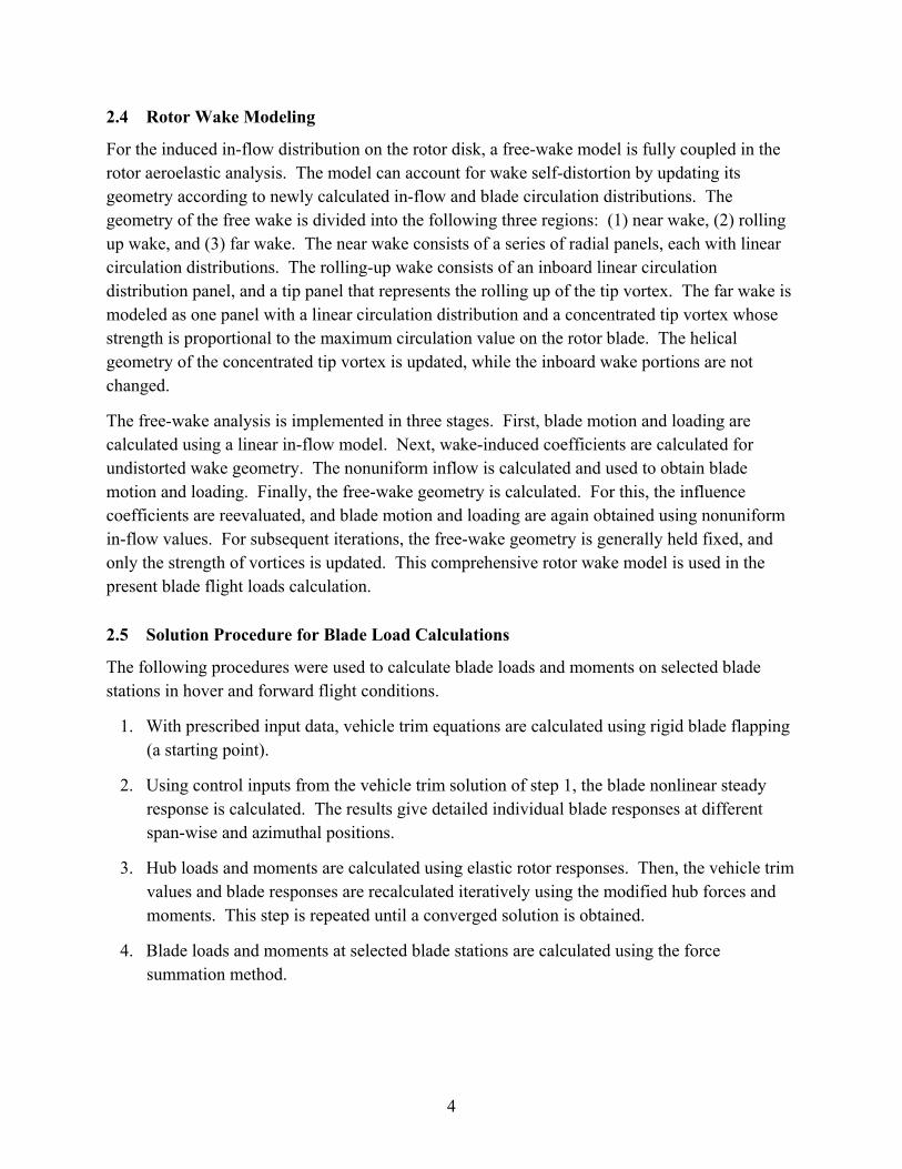
The computed blade bending moments were also correlated with the flight test data. In reference (5), three flap bending moment values are given at three inboard blade stations—stations 31 (r/R = 0.148), 40 (r/R = 0.191), and 50 (r/R = 0.238), respectively. In reference (6), only one bending value is given at the outboard blade station 96 (r/R = 0.457). These flight values were replicated and shown in table 3. Also, shown in the fourth column of the table are the peak-to-peak values of the moments. The peak-to-peak value is a good indication of loading on the structural component. It is seen that the bending moment is largest inboard and decreases outboard.
Figure 4 shows the correlation of the UMARC flap-bending moments with the flight test data. There are some discrepancies between the UMARC results and the flight test data. However, considering the complexities associated with rotor loads and vibration analysis, a reasonably good agreement is observed. In particular, the general trend and the peak-to-peak magnitude of the moments are well correlated with flight test data, especially at inboard blade stations.
Blade Station (r/R)
Cen
trifu
galF
orce
(lbf)
0 0.2 0.4 0.6 0.8 10
10000
20000
30000
40000
50000
Uniform Blade AssumptionUMARC Code Prediction (Non-Uniform Blade FEM Model)Flight Test Data (Model 406LM)
Correlation of Axial Blade Loads on OH-58D KW Blade
Blade TipBlade Root
VN = 120 knots, GW = 4500 lbs
9
Table 3. Flap bending moments of Bell model 406T helicopter main rotor blade.
Blade Station
(r/R)
Mean Value (in-lbf)
Oscillatory Value
(in-lbf)
Peak-to-peak Value (in-lbf)
0.148 2125 2725± 5450 0.191 1725 2360± 4720 0.238 1275 2000± 4000 0.457 –180 780± 1560
Figure 4. Correlation of flap bending moment along blade span (µ = 0.28).
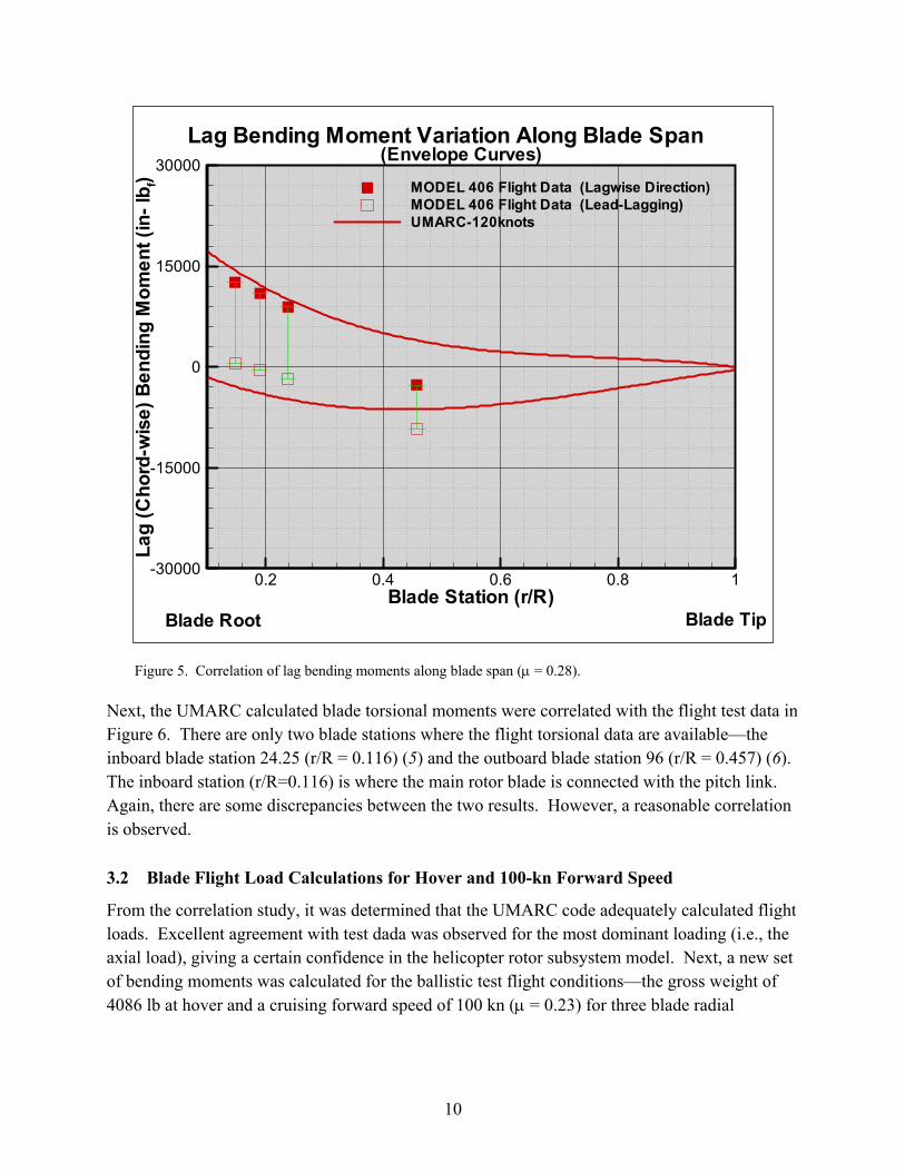
Figure 5 shows the correlation of UMARC lag bending moments with flight test data. Again, there are some discrepancies between the analytical results and the test data. A comparison reveals that the UMARC values are slightly greater than the test data values. However, a reasonable correlation with the test data is observed, and the general trend is especially well correlated.
Blade Station (r/R)
Flap
Bend
ing
Mom
ent(
in-l
b f)
0.2 0.4 0.6 0.8 1-10000
-5000
0
5000
10000MODEL 406 DATA (Flapping Up)MODEL 406 DATA (Flapping Down)UMARC-120knots
Flap Bending Moment Variation Along Blade Span(Envelope Curves)
Blade TipBlade Root
10
Figure 5. Correlation of lag bending moments along blade span (µ = 0.28).
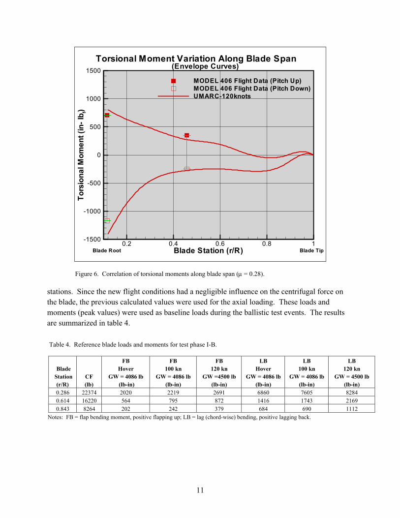
Next, the UMARC calculated blade torsional moments were correlated with the flight test data in Figure 6. There are only two blade stations where the flight torsional data are available—the inboard blade station 24.25 (r/R = 0.116) (5) and the outboard blade station 96 (r/R = 0.457) (6). The inboard station (r/R=0.116) is where the main rotor blade is connected with the pitch link. Again, there are some discrepancies between the two results. However, a reasonable correlation is observed.
3.2 Blade Flight Load Calculations for Hover and 100-kn Forward Speed
From the correlation study, it was determined that the UMARC code adequately calculated flight loads. Excellent agreement with test dada was observed for the most dominant loading (i.e., the axial load), giving a certain confidence in the helicopter rotor subsystem model. Next, a new set of bending moments was calculated for the ballistic test flight conditions—the gross weight of 4086 lb at hover and a cruising forward speed of 100 kn (µ = 0.23) for three blade radial
Blade Station (r/R)
Lag
(Cho
rd-w
ise)
Bend
ing
Mom
ent(
in-l
b f)
0.2 0.4 0.6 0.8 1-30000
-15000
0
15000
30000MODEL 406 Flight Data (Lagwise Direction)MODEL 406 Flight Data (Lead-Lagging)UMARC-120knots
Lag Bending Moment Variation Along Blade Span(Envelope Curves)
Blade Root Blade Tip
11
Figure 6. Correlation of torsional moments along blade span (µ = 0.28).
stations. Since the new flight conditions had a negligible influence on the centrifugal force on the blade, the previous calculated values were used for the axial loading. These loads and moments (peak values) were used as baseline loads during the ballistic test events. The results are summarized in table 4.
Table 4. Reference blade loads and moments for test phase I-B.
Blade
Station (r/R)
CF (lb)
FB Hover
GW = 4086 lb (lb-in)
FB 100 kn
GW = 4086 lb(lb-in)
FB 120 kn
GW =4500 lb(lb-in)
LB Hover
GW = 4086 lb (lb-in)
LB 100 kn
GW = 4086 lb (lb-in)
LB 120 kn
GW = 4500 lb (lb-in)
0.286 22374 2020 2219 2691 6860 7605 8284 0.614 16220 564 795 872 1416 1743 2169 0.843 8264 202 242 379 684 690 1112
Notes: FB = flap bending moment, positive flapping up; LB = lag (chord-wise) bending, positive lagging back.
Blade Station (r/R)
Tors
iona
lMom
ent(
in-l
b f)
0.2 0.4 0.6 0.8 1-1500
-1000
-500
0
500
1000
1500MODEL 406 Flight Data (Pitch Up)MODEL 406 Flight Data (Pitch Down)UMARC-120knots
Torsional Moment Variation Along Blade Span(Envelope Curves)
Blade Root Blade Tip
12
4. Summary
An aeroelastic analysis was conducted to calculate flight loads on the OH-58D KW main rotor blade for hover and cruise forward-flight conditions. Centrifugal force and flap and lag bending moments were calculated using the UMARC code. The calculated loads were correlated with flight test data for the Bell model 406LM helicopter to validate the analysis. The correlation showed good general agreement between the test data and analytical results. After the correlation study, blade loads were calculated for the desired ballistic test conditions.
In the present study, the UMARC comprehensive helicopter aeroelastic analysis, based on FE methodology in both space and time coordinates, was conducted to analytically calculate the flight loads. In spite of it being computer-intensive, its benefit must be appreciated as a powerful analytical tool to validate simple design-oriented analysis.
13
5. References
1. Polyak, S. F. Detailed Test Plan for U.S. Army OH-58D Kiowa Warrior Live Fire Test and Evaluation: Main Rotor Blade Ballistic Vulnerability Test Phase I-B (Quasi-Static); ARL-MR-0549, U.S. Army Research Laboratory: Aberdeen Proving Ground, MD, March 2003.
2. Bir, G. S.; Chopra, I.; Kim, K. C.; Wang, J.; Smith, E.; Vellaichamy, S.; Ganguli, R.; Nixon, M; Torok, S. University of Maryland Advanced Rotorcraft Code (UMARC) Theory Manual; AERO report no. 94-18; University of Maryland, College Park, MD, July 1994.
3. Kim, K. C. Helicopter Trim Calculation in Forward Flight. Proceedings of the 1993 Summer Computer Simulation Conference, ISBN:1-5655-057-9, Boston, MA, July 1993, pp 374–379.
4. Kim, K. C. Analytical Investigation Into the Helicopter Vibration Resulting From Main Rotor Blade (MRB) Ballistic Damage; ARL-TR-1985; U.S. Army Research Laboratory: Aberdeen Proving Ground, MD, June 1999.
5. Bell Helicopter TEXTRON. Fatigue Test of The Model 406T Main Rotor Blade, Inboard Section, PART No 406-015-001, PART I –Test Plan & PART II – Test Results; report no. 406-998-001; Fort Worth, TX, February 1986.
6. Bell Helicopter TEXTRON. Fatigue Test of The Model 406T Main Rotor Blade, Outboard Section, PART No 406-015-001, Part II – Test Results; report no. 406-998-002; Fort Worth, TX, March 1986.
7. Bell Helicopter TEXTRON. OH-58D Air Vehicle Technical Description Data; report no. 406-099-026; Fort Worth, TX, May 1984.
8. Bell Helicopter TEXTRON. Model 406 Performance Analysis; report no. 406-099-080; Fort Worth, TX, August 1983.
14
List of Abbreviations and Symbols
A Rotor disk area, πR2 cm Mean blade chord length
CW Helicopter weight coefficient, 2)( RAWΩρ
E Young’s modulus EIy Effective flap bending stiffness EIz Effective lag (chord) bending stiffness G Shear modulus GJ Effective sectional torsion stiffness Iy, Iz Blade cross-sectional moment of inertia about y and z axis, respectively J Polar moment of inertia li Length of the ith beam element mo Reference blade section mass Nb Number of rotor blades R Blade radius uT Row vector of unknowns in vehicle trim equations u Blade displacement in the axial direction V Helicopter forward speed v Blade displacement in the lead-lag direction W Helicopter weight w Blade displacement in the flap-wise direction αs Longitudinal shaft tilt θ.75 Main rotor collective pitch angle at 75% blade radius θ1c, θ1s Lateral and longitudinal cyclic trim pitch angles, respectively θtail Tail rotor collective pitch angle at root
µ Advance ratio, R
VΩ
σ Rotor solidity ratio, Rc N mb
π
φ Elastic blade twist about the elastic axis φs Lateral shaft tilt ρ Air density Ω Rotor rotational speed
NO. OF NO. OF COPIES ORGANIZATION COPIES ORGANIZATION
15
1 DEFENSE TECHNICAL (PDF INFORMATION CENTER Only) DTIC OCA 8725 JOHN J KINGMAN RD STE 0944 FT BELVOIR VA 22060-6218 1 COMMANDING GENERAL US ARMY MATERIEL CMD AMCRDA TF 5001 EISENHOWER AVE ALEXANDRIA VA 22333-0001 1 INST FOR ADVNCD TCHNLGY THE UNIV OF TEXAS AT AUSTIN 3925 W BRAKER LN STE 400 AUSTIN TX 78759-5316 1 US MILITARY ACADEMY MATH SCI CTR EXCELLENCE MADN MATH THAYER HALL WEST POINT NY 10996-1786 1 DIRECTOR US ARMY RESEARCH LAB AMSRD ARL D DR D SMITH 2800 POWDER MILL RD ADELPHI MD 20783-1197 1 DIRECTOR US ARMY RESEARCH LAB AMSRD ARL CS IS R 2800 POWDER MILL RD ADELPHI MD 20783-1197 3 DIRECTOR US ARMY RESEARCH LAB AMSRD ARL CI OK TL 2800 POWDER MILL RD ADELPHI MD 20783-1197 3 DIRECTOR US ARMY RESEARCH LAB AMSRD ARL CS IS T 2800 POWDER MILL RD ADELPHI MD 20783-1197
ABERDEEN PROVING GROUND 1 DIR USARL AMSRD ARL CI OK TP (BLDG 4600)
NO. OF NO. OF COPIES ORGANIZATION COPIES ORGANIZATION
16
1 OASD C3I J BUCHHEISTER RM 3D174 6000 DEFENSE PENTAGON WASHINGTON DC 20301-6000 1 OUSD(AT)/S&T AIR WARFARE R MUTZELBURG RM 3E139 3090 DEFENSE PENTAGON WASHINGTON DC 20301-3090 1 OUSD(AT)/S&T LAND WARFARE A VIILU RM 3B1060 3090 DEFENSE PENTAGON WASHINGTON DC 20310-3090 1 UNDER SECY OF THE ARMY DUSA OR RM 2E660 102 ARMY PENTAGON WASHINGTON DC 20310-0102 1 ASST SECY ARMY ACQSTN LOGISTICS & TECH SAAL ZP RM 2E661 103 ARMY PENTAGON WASHINGTON DC 20310-0103 1 ASST SECY ARMY ACQSTN LOGISTICS & TECH SAAL ZS RM 3E448 103 ARMY PENTAGON WASHINGTON DC 20310-0103 1 DIRECTOR FORCE DEV DAPR FDZ RM 3A522 460 ARMY PENTAGON WASHINGTON DC 20310-0460 1 US ARMY TRADOC ANL CTR ATRC W A KEINTZ WSMR NM 88002-5502 1 USARL AMSRD ARL SL M J PALOMO WSMR NM 88002-5513
1 USARL AMSRD ARL SL EA R FLORES WSMR NM 88002-5513 1 USARL AMSRD ARL SL EI J NOWAK FT MONMOUTH NJ 07703-5601
ABERDEEN PROVING GROUND 1 US ARMY DEV TEST COM CSTE DTC TT T APG MD 21005-5055 1 US ARMY EVALUATION CTR CSTE AEC SVE R BOWEN 4120 SUSQUEHANNA AVE APG MD 21005-3013 1 US ARMY EVALUATION CTR CSTE AEC SVE S R POLIMADEI 4120 SUSQUEHANNA AVE APG MD 21005-3013
1 US ARMY EVALUATION CTR CSTE AEC SV L R LAUGHMAN 4120 SUSQUEHANNA AVE APG MD 21005-3013 13 DIR USARL AMSRD ARL SL J BEILFUSS P DEITZ AMSRD ARL SL B J FRANZ M PERRY P TANENBAUM AMSRD ARL SL BB D BELY D FARENWALD S JUARASCIO M RITONDO AMSRD ARL SL BD R GROTE

NO. OF COPIES ORGANIZATION
17
AMSRD ARL SL BE L ROACH AMSRD ARL SL E M STARKS AMSRD ARL SL EC J FEENEY E PANUSKA
NO. OF COPIES ORGANIZATION
18
1 NASA LANGLEY RESCH CTR VEHICLE TECH DIR M NIXON MS 266 HAMPTON VA 23665 1 US ARMY EVALUATION CTR CSTE AEC SV LF 4120 SUSQUEHANNA AVE APG MD 21005
ABERDEEN PROVING GROUND 20 DIR USARL AMSRD ARL SL B AMSRD ARL SL BB D JORDAN M KUNKEL S MOULSDALE B WALTHER AMSRD ARL SL BD S POLYAK B SMITH J FRIES D TEN BROECK K KIM (10 CPS) AMSRD ARL SL BE E FIORAVANTE
![Active Helicopter Rotor Control Using Blade-Mounted Actuators2-1 Block diagram of coupled rotor and inflow dynamics. Adapted from Pitt and Peters [35]. ..... 34 2-2 Helicopter rotor](https://static.fdocuments.in/doc/165x107/5f440e16ded27235c7483c01/active-helicopter-rotor-control-using-blade-mounted-actuators-2-1-block-diagram.jpg)