TOGAF 9 Fundamental: 4. Key Terminology Romi Satria Wahono [email protected] .

UNCLASSIFIED
Development of Virtual Blade Model for Modelling Helicopter Rotor Downwash in OpenFOAM
Stefano Wahono
Aerospace Division
Defence Science and Technology Organisation
DSTO-TR-2931
ABSTRACT This report documents the development of a computational model to simulate the complex flow induced by helicopter rotors, using an open-source computational fluid dynamics (CFD) code, OpenFOAMTM. This computational code is now being used to perform large-scale multi-physics simulations of the flow field around helicopters including exhaust plumes and their airframe impingement. The rotor downwash model was validated against available experimental data on rotor-fuselage interactions published by the Georgia Institute of Technology. The OpenFOAM predicted result was also shown to compare favourably with ANSYS Fluent predictions.
RELEASE LIMITATION
Approved for public release
UNCLASSIFIED

UNCLASSIFIED
UNCLASSIFIED
Produced by Aerospace Division DSTO Defence Science and Technology Organisation 506 Lorimer St Fishermans Bend, Victoria 3207 Australia Telephone: 1300 3333 362 Fax: (03) 9626 7999 AR 015-836 Commonwealth of Australia 2014 December 2013 APPROVED FOR PUBLIC RELEASE

UNCLASSIFIED
UNCLASSIFIED
Development of Virtual Blade Model for Modelling Helicopter Rotor Downwash in OpenFOAM
Executive Summary The Infrared Signatures and Aerothermodynamics (IRSA) group within DSTO is tasked with providing measurement-validated infrared signature models of air vehicles to the Australian Defence Force (ADF). In general, both fixed and rotary-wing aircraft will exhibit a significant area of unobscured hot exhaust surface. For such aircraft, the infrared signature is dominated by direct emissions from these unobscured hot surfaces, while the signature contribution from surface reflections and plume emissions can largely be neglected without great loss of accuracy. However, for low-observable aircraft, like helicopters fitted with infrared suppressors, a lack of observable exhaust surfaces means that this simplification does not apply. Infrared-suppressed helicopters are becoming increasingly important to the ADF and an understanding of their infrared signature requires a much more comprehensive understanding of their associated air and exhaust flows. Infrared suppression systems principally function by denying direct line-of-sight to hot engine exhaust surfaces at tactically critical viewing aspects. Consequently, aircraft fitted with infrared suppression systems have signatures which are dominated by exhaust plume emissions, emissions from airframe surfaces incidentally heated by exhaust impingement and indirect reflections of directly obscured hot surfaces on rotor blades, wings, cavities, etc. In the case of a suppressed helicopter, the ability to model the complex interaction between the hot engine exhaust plume and the rotor downwash is essential to the prediction of its infrared signature. Downwash-plume-crosswind interaction determines the magnitude and disposition of volumetric exhaust gas emission and localised surface emission due to plume impingement. This report documents the development of a computational model to simulate the complex flow induced by helicopter rotors, using an open-source computational fluid dynamics (CFD) code, OpenFOAMTM. This computational code is now being used to perform large-scale multi-physics simulations of the flow field around helicopters including exhaust plumes and their airframe impingement. These simulations exploit the benefit of combining free open-source software with historically inexpensive computer cluster hardware performance to accurately model the signatures of low-observable aircraft.

UNCLASSIFIED
UNCLASSIFIED
Author
Stefano Wahono Aerospace Division Stefano Wahono graduated with double degree in Mechanical and Aerospace Engineering in 2004 from Monash University with first class honours. He then undertook research work at Monash University in the experimental and computational fluid mechanics, particularly on the mechanics of spray formation and swirling jets. In 2006, Stefano took up a position as an aircraft structural integrity engineer for the RAAF with QinetiQ Australia. During his time at QinetiQ, Stefano undertook various structural integrity management and regulation work for the RAAF, which included undertaking of the structural life assessment of the PC-9/A fleet, structural life analysis and certification of the Electronic Warfare Self Protection on the AP-3C fleet, and the Ageing Aircraft Structural Audit for the F/A-18 fleet. Since 2009, Stefano has worked at DSTO on a variety of projects including using computational fluid dynamics to significantly re-design the flow path and performance of DSTO’s Concept-2 infrared suppressor for the CH-47D. Stefano also used CFD to analyse the airwake about the LHD flight deck for helicopter operations. Stefano is a member of the Infrared Signatures and Aerothermodynamics group within Aerospace Division. His current primary research interest is in the area of complex turbulent flows around aircraft and in propulsion system elements for accurate signature prediction.
____________________ ________________________________________________

UNCLASSIFIED DSTO-TR-2931
UNCLASSIFIED
Contents
1. INTRODUCTION............................................................................................................... 1
2. PHYSICAL MODEL AND ASSUMPTIONS................................................................. 3
2.1 Overview of Rotor Blade Modelling Techniques in CFD ................................ 3
2.2 Overview of Rotor Aerodynamics ......................................................................... 4
2.2.1 Brief Description of a Helicopter Rotor................................................ 4
2.2.2 Blade Geometry ....................................................................................... 6
2.2.3 Rotor Coning and Flapping ................................................................... 6
2.3 Model Description.................................................................................................... 8
2.3.1 The Virtual Blade Model ........................................................................ 8
2.3.2 Frame of Reference Transformations.................................................... 9
2.3.3 Blade Forces Calculation ...................................................................... 11
2.3.4 Blade Section Lift and Drag ................................................................. 13
2.3.5 Blade Tip Effect...................................................................................... 14
2.3.6 Momentum Sources .............................................................................. 14
2.3.7 Rotor Trim Model.................................................................................. 17
2.3.8 Dimensionless Parameters ................................................................... 19
2.3.9 Summary................................................................................................. 20
3. MODEL IMPLEMENTATION IN OPENFOAM........................................................ 21
3.1 Overview .................................................................................................................. 21
3.2 Applicable OpenFOAM Version ......................................................................... 21
3.3 The Flow Solvers..................................................................................................... 22
3.3.1 Overview of RANS Solvers in OpenFOAM ...................................... 22
3.3.2 Overview of the rhoSimpleFoam Solver ............................................ 23
3.3.3 Creating a New rhoSimpleSourceFoam Solver................................. 25
3.3.4 The basicSource Class ........................................................................... 27
3.3.5 Overview of the VBM Library Classes ............................................... 28
3.4 The VBM Library in OpenFOAM ....................................................................... 31
3.4.1 The rotorDiskSource Class ................................................................... 31
3.4.2 The rotorDiskSource Input/Output (IO) ........................................... 34
3.4.3 The Rotor trimModel Class.................................................................. 35
3.5 Compiling the Code ............................................................................................... 37

UNCLASSIFIED DSTO-TR-2931
UNCLASSIFIED
3.5.1 Preparation ............................................................................................. 37
3.5.2 Linking the VBM Library to the Standard OpenFOAM Libraries . 38
3.5.3 Compiling the VBM Library (librotorDiskSource.so) ...................... 39
3.6 Updating the VBM Code for Compatibility with Future OpenFOAM Version...................................................................................................................... 40
4. CASE SETUP IN OPENFOAM USING THE ROTORDISKSOURCE LIBRARY 42
4.1 Case Setup ................................................................................................................ 42
4.1.1 File Structure .......................................................................................... 42
4.1.2 Time Directory (Output) ...................................................................... 45
4.2 Specifying the rotorDiskSource Properties in the sourceProperties Dictionary File ......................................................................................................... 46
4.2.1 Basic Selection Mechanism................................................................... 46
4.2.2 Specifying Basic rotorDiskSource Coefficients ................................. 48
4.2.3 Specifying Blade Trim Parameters...................................................... 50
4.2.4 Specifying Blade Geometry and Section Profile................................ 51
4.2.5 Specifying Section Profile Lift and Drag Curves .............................. 52
4.3 Mesh Requirement ................................................................................................. 53
4.3.1 Generating Rotor Disk Mesh Using ANSYS Gambit and ANSYS TGrid for Use in OpenFOAM.............................................................. 56
4.4 Setting Up the Boundary Conditions.................................................................. 58
4.4.1 Overview of Boundary Patches and Boundary Conditions in OpenFOAM............................................................................................ 59
4.4.2 Setting Up Boundary Conditions for an OpenFOAM Case ............ 60
4.4.3 Rotor Disk Boundary Conditions in OpenFOAM ............................ 61
4.5 Solution Driving Strategy ..................................................................................... 65
4.5.1 Overview ................................................................................................ 65
4.5.2 Appropriateness of Boundary Conditions......................................... 66
4.5.3 Appropriateness of Initial Condition ................................................. 67
4.5.4 Cell Orthogonality Consideration....................................................... 68
4.5.5 Selection of Numerical Discretisation Scheme.................................. 69
4.5.6 Selection of Linear Solvers ................................................................... 76
4.5.7 Under-Relaxation Factors..................................................................... 77
4.6 Plotting Results on the Rotor Disk Surface using ParaviewTM...................... 80

UNCLASSIFIED DSTO-TR-2931
UNCLASSIFIED
4.6.1 Plotting Flow-field Variables on the Rotor Disk using a New Plane Source in Paraview ..................................................................... 80
4.6.2 Plotting Flow-field Variables on the Rotor Disk using a VTK File. 81
5. VALIDATION AND VERIFICATION TEST CASE.................................................. 82
5.1 Overview .................................................................................................................. 82
5.2 Summary of Georgia Institute of Technology (Georgia Tech) Rotor-Airframe Interaction Experimental Setup.......................................................... 82
5.3 CFD Model ............................................................................................................... 83
5.3.1 Geometry and Mesh.............................................................................. 83
5.3.2 Boundary Conditions............................................................................ 84
5.3.3 Rotor Modelling..................................................................................... 85
5.3.4 FV Discretisation Scheme and Linear Solvers ................................... 85
5.3.5 ANSYS Fluent Case Setup.................................................................... 86
5.3.6 Solution Driving Strategy and Residual Trend................................. 86
5.4 Verification and Validation Result ..................................................................... 87
5.4.1 Calculated Rotor Thrust and Moments.............................................. 87
5.4.2 Untrimmed Rotor Simulation Result.................................................. 88
5.4.3 The Effect of Thrust and Moments Trimming................................... 97
6. CONCLUSIONS AND RECOMMENDATIONS..................................................... 102
7. REFERENCES .................................................................................................................. 102
APPENDIX A SOURCE CODE FOR THE ROTORDISKSOURCE........................ 106
A.1. High Level Description of the Source Code Files.................. 106
A.2. Source Code for the rotorDiskSource....................................... 110
UNCLASSIFIED DSTO-TR-2931
UNCLASSIFIED
A.2.1 rotorDiskSource.H ......................................................... 110
A.2.2 rotorDiskSource.C.......................................................... 115
A.2.3 rotorDiskSourceTemplates.C ....................................... 128
A.2.4 rotorDiskSourceI.H........................................................ 129
A.2.5 bladeModel.H................................................................. 130
A.2.6 bladeModel.C ................................................................. 132
A.2.7 profileModel.H............................................................... 135
A.2.8 profileModel.C ............................................................... 137
A.2.9 profileModelList.H ........................................................ 139
A.2.10 profileModelList.C......................................................... 141
A.2.11 lookupProfile.H.............................................................. 143
A.2.12 lookupProfile.C .............................................................. 145
A.2.13 seriesProfile.H ................................................................ 147
A.2.14 seriesProfile.C................................................................. 149
A.2.15 trimModel.H................................................................... 151
A.2.16 trimModel.C ................................................................... 153
A.2.17 trimModelNew.C........................................................... 154
A.2.18 fixedTrim.H .................................................................... 155
A.2.19 fixedTrim.C..................................................................... 157
A.2.20 targetForceTrim.H ......................................................... 159
A.2.21 targetForceTrim.C.......................................................... 161
A.2.22 Make/files....................................................................... 165
A.2.23 Make/options................................................................. 165
APPENDIX B A SAMPLE CASE SET UP USING THE GEORGIA TECH VALIDATION CASE FOR RUNNING RHOSIMPLESOURCEFOAM SOLVER WITH ROTORDISKSOURCE ACTIVE......................................................... 166
B.1. Overview........................................................................................ 166
B.2. Case Configuration Files............................................................. 167
UNCLASSIFIED DSTO-TR-2931
UNCLASSIFIED
B.2.1 Constant/polyMesh/boundary................................... 167
B.2.2 constant/RASProperties ............................................... 168
B.2.3 constant/thermophysicalProperties ........................... 169
B.2.4 constant/transportProperties....................................... 170
B.2.5 constant/sourcesProperties.......................................... 171
B.2.6 0/p ................................................................................... 174
B.2.7 0/U................................................................................... 175
B.2.8 0/T ................................................................................... 176
B.2.9 0/k.................................................................................... 177
B.2.10 0/epsilon ......................................................................... 178
B.2.11 0/mut............................................................................... 179
B.2.12 0/alphat........................................................................... 180
B.2.13 system/controlDict........................................................ 181
B.2.14 system/fvSchemes......................................................... 182
B.2.15 system/fvSolution ......................................................... 183
B.2.16 system/decomposeParDict .......................................... 185
B.2.17 monitorResiduals ........................................................... 186
B.2.18 runCaseOnSeadragonCluster....................................... 187

UNCLASSIFIED DSTO-TR-2931
UNCLASSIFIED
List of Figures
Figure 2.1: Rotor disk schematic showing definition of and r............................................... 5
Figure 2.2: Blade motion schematic at an arbitrary azimuthal position, , on the rotor disk............................................................................................................................................................. 7
Figure 2.3: A schematic of the RSP, LRF and TPP on a flapping and coning blade .............. 8
Figure 2.4: Schematic of the blade element in the RSP stationary cylindrical frame of reference and the LRF rotating cylindrical frame of reference ................................................ 10
Figure 2.5: Blade element ............................................................................................................. 11
Figure 2.6: Schematic of the forces acting on the blade element in the LRF ......................... 12
Figure 2.7: Typical structured mesh used to model the rotor disk using the VBM ............. 15
Figure 3.1: Implementation of the SIMPLE algorithm in rhoSimpleFoam......................... 24
Figure 3.2: UEqn.H in rhoSimpleFoam ...................................................................................... 24
Figure 3.3: Modified UEqn.H in rhoSimpleFoam with basicSource term............................. 25
Figure 3.4: Directory structure for an application in OpenFOAM ......................................... 26
Figure 3.5: Modified Make/files and Make/options for compiling rhoSimpleSourceFoam........................................................................................................................................................... 26
Figure 3.6: Class hierarchy of basicSource class in OpenFOAM ............................................ 27
Figure 3.7: Overview of the directory and file structure of the VBM source code in OpenFOAM..................................................................................................................................... 29
Figure 3.8: Class declaration in rotorDiskSource.H showing inheritance from basicSource........................................................................................................................................................... 30
Figure 3.9: Implementation of the virtual void addSup() in the rotorDiskSource class...... 31
Figure 3.10: Adding rotorDiskSource class to the basicSource runTimeSelectionTable ..... 31
Figure 3.11: Implementation of the VBM using rotorDiskSource class and rhoSimpleSourceFoam solver in OpenFOAM ........................................................................... 33
Figure 3.12: Linux shell output of rotorDiskSource during runtime ..................................... 34
Figure 3.13: Implementation of the targetForceTrim model in the rotorDiskSource class . 36

UNCLASSIFIED DSTO-TR-2931
UNCLASSIFIED
Figure 3.14: Linux shell output of targetForceTrim class during runtime..................... 37
Figure 3.15: Content of the “Make/options” needed to compile rotorDiskSource ............. 39
Figure 3.16: Content of the “Make/files” needed to compile rotorDiskSource ................... 39
Figure 4.1: OpenFOAM minimal case directory structure required for running a RANS simulation using the rotorDiskSource library............................................................................ 43
Figure 4.2: Source term model selector in the sourceProperties file ...................................... 47
Figure 4.3: Basic rotorDiskCoeffs parameters in the sourceProperties file ........................... 48
Figure 4.4: Methods of specifying inlet flow into the rotor disk in the sourceProperties file........................................................................................................................................................... 49
Figure 4.5: Cyclic and collective pitch trim parameters in the sourceProperties file........... 50
Figure 4.6: Blade geometry and profile specification in the sourceProperties file............... 52
Figure 4.7: Airfoil section lift and drag curves specification in the sourceProperties file... 53
Figure 4.8: An example of rotor disk mesh using structured hexahedral cells .................... 54
Figure 4.9: An example of pyramid cells attachment on the rotor disk mesh in a fully unstructured tetrahedral cell domain – generated using ANSYS TGrid ............................... 55
Figure 4.10: OpenFOAM user environment .............................................................................. 56
Figure 4.11: polyMesh directory structure in an OpenFOAM case........................................ 57
Figure 4.12: polyMesh directory structure in an OpenFOAM case........................................ 58
Figure 4.13: Boundary patch hierarchy in an OpenFOAM case (reproduced from Reference 13) ................................................................................................................................... 60
Figure 4.14: Using the “timeVarying” option of the flowRateInletVelocity boundary condition across a mass flow rate inlet boundary ................................................... 68
Figure 4.15: Recommended URF setup for running rhoSimpleSourceFoam solver for a moderately compressible flow case ............................................................................................. 77
Figure 5.1: Georgia Tech rotor - airframe interaction wind tunnel experimental setup – reproduced from Reference 23 ..................................................................................................... 83
Figure 5.2: Mesh configuration.................................................................................................... 84
Figure 5.3: Cl and Cd profiles for NACA 0015 airfoil over a range of AOA ........................ 86

UNCLASSIFIED DSTO-TR-2931
UNCLASSIFIED
Figure 5.4: Residual curves of the Georgia Tech case run using the rhoSimpleSourceFoam solver ................................................................................................................................................ 87
Figure 5.5: Mean static gauge pressure contour plot on the x-z plane which passes through the rotor disk centre ....................................................................................................................... 89
Figure 5.6: Mean static gauge pressure contour plot on the y-z plane which passes through the rotor disk centre ....................................................................................................................... 90
Figure 5.7: Computed mean Cp on the fuselage without force and moment trimming...... 91
Figure 5.8: Comparison of measured and computed mean Cp on the fuselage without force and moment trimming......................................................................................................... 92
Figure 5.9: Schematic representation of the instantaneous flow-field above the fuselage – reproduced from Reference 22 ..................................................................................................... 92
Figure 5.10: Gauge static pressure contour on the rotor disk top surface............................. 93
Figure 5.11: Gauge static pressure contour on the rotor disk bottom surface ...................... 93
Figure 5.12: Streamlines coloured by velocity magnitude. Velocity magnitude contour plot is shown on the rotor disk bottom surface ................................................................................. 94
Figure 5.13: Contour plot of mean downwash velocity measured 12.7 mm below the rotor disk - negative values denote upflow........................................................................................ 95
Figure 5.14: Velocity measurement location at Reference 20 .................................................. 96
Figure 5.15: Comparison of measured and computed mean dtreamwise velocity profile (Top) and downwash velocity profile (Bottom) at Z/r=0.178 ................................................. 97
Figure 5.16: Comparison of measured and computed mean Cp on the fuselage with the thrust and moment trimming activated...................................................................................... 99
Figure 5.17: Comparison of measured and computed streamwise velocity (Top) and downwash velocity (Bottom) at Z/r=0.178 with the thrust and moment trimming activated......................................................................................................................................................... 100
Figure 5.18: Mean Cp on the fuselage with the thrust and moment trimming activated and using a tip factor of 0.96............................................................................................................... 101
Figure 6.1: Flow streamlines coloured by temperature used for visualising the interaction between the exhaust plume and the rotor downwash around the MRH-90 in hover outside of ground effect............................................................................................................................. 103
Figure 6.2: Predicted MRH-90 fuselage temperature in hover with different prevailing relative wind angles. .................................................................................................................... 103

UNCLASSIFIED DSTO-TR-2931
UNCLASSIFIED
List of Tables
Table 3.1: List of standard OpenFOAM flow solvers that are applicable to the IRSA Group ............................................................................................................................................... 22
Table 4.1: Brief description of the files in a standard OpenFOAM case .............................. 44
Table 4.2: Specifying writeData control in the controlDict File ............................................ 46
Table 4.3: Mapping of ANSYS Fluent boundary conditions to standard OpenFOAM numerical type boundary conditions .......................................................................................... 62
Table 4.4: Mapping of ANSYS Fluent discretisation schemes to standard OpenFOAM discretisation schemes – excluding Laplacian schemes............................................................ 70
Table 4.5: Surface normal gradient discretisation schemes for specifying Laplacian schemes in OpenFOAM................................................................................................................. 74
Table 4.6: Recommended second order accurate discretisation scheme set up for use with the rhoSimpleFoam solver ............................................................................................................ 75
Table 4.7: Recommended linear Solver Set Up for Use with the rhoSimpleSourceFoam Solver................................................................................................................................................ 78
Table 5.1: Calculated rotor thrust and moments..................................................................... 88
Table 5.2: Rotor trim parameters for the GIT validation case ............................................... 98
Table A.1: Summary of all source files in the rotorDiskSource code ................................. 106
Table B.1: Summary of a sample rhoSimpleSourceFoam case configuration files........... 166

UNCLASSIFIED DSTO-TR-2931
UNCLASSIFIED
Glossary ADF Australian Defence Force
ADO Australian Defence Organisation
AOA Angle-Of-Attack
AOD Air Operation Division
AVD Air Vehicles Division
BET Blade Element Theory
C++ Object-Oriented Programming Language
CFD Computational Fluid Dynamics
CPU Central Processing Unit
DSTO Defence Science and Technology Organisation
FV Finite Volume
FVM FV Method
GIT Georgia Institute of Technology
GUI Graphical User Interface
HPC High Performance Computer
IO Input/Output
IR Infra Red
IRSA Infrared Signatures and Aerothermodynamics
LDV Laser Doppler Velocimetry
LRF Local Rotor Frame of reference
NVD Normalised Variation Diminishing
OpenCFD Trademark holder of OpenFOAM CFD Code
OpenFOAM Open Field Operation And Manipulation
PBS Portable Batch System
PDE Partial Differential Equation
PISO Pressure Implicit with Splitting of Operators
RANS Reynolds Averaged Navier Stokes Equation
RSP Rotor Shaft Plane
RWO Rotary Wing Operations
SIMPLE Semi-Implicit Method for Pressure Linked Equations
TPP Rotor Tip Path Plane
TVD Total Variation Diminishing
URF Under Relaxation Factor
VBM Virtual Blade Element Method
VTK Visualisation Tool Kit file format

UNCLASSIFIED DSTO-TR-2931
UNCLASSIFIED
Notation rotor blade angular velocity (rad/s)
zr ,, stationary cylindrical coordinate system local to the rotor plane for zero RSP pitch-bank angles
zyx ,, global Cartesian coordinate system
r radial position vector along the blade span
rotor azimuth angle
LRFr unit radial vector in the LRF rotating cylindrical frame of reference
LRF unit vector tangential to the instantaneous blade path in the LRF rotating cylindrical frame of reference
LRFz unit vector normal to the instantaneous blade path in the LRF rotating cylindrical frame of reference
RSPr unit radial vector in the RSP rotating cylindrical frame of reference
RSP unit vector tangential to the line of constant radius in the RSP rotating cylindrical frame of reference
RSPz unit vector normal to the RSP rotating cylindrical frame of reference
rotor disk solidity ratio
bN number of blade on the rotor
J rotor advance ratio
R rotor disk radius (m)
g blade geometric angle-of-attack (deg)
collective blade collective angle-of-attack (deg)
sincos BA blade longitudinal and lateral cyclic pitch angles (deg)
total blade flapping angle (deg)
0 blade coning angle (deg)
sincos 11 sc first harmonic components of the blade longitudinal and lateral flapping angles (deg)
i induced angle-of-attack (deg)

UNCLASSIFIED DSTO-TR-2931
UNCLASSIFIED
e blade effective angle-of-attack (deg)
LRFi induced angle-of-attack in the rotor LRF rotating cylindrical frame of reference (deg)
LRFe blade effective angle-of-attack in the rotor LRF rotating cylindrical frame of reference (deg)
blade twist angle (deg)
zyx vvv ,, velocity components (m/s) in the stationary global Cartesian frame of reference
RSPRSPRSP zyx vvv ,, velocity components (m/s) in the RSP stationary Cartesian frame
of reference
LRFLRFLRF zr vvv ,, velocity components (m/s) in the LRF rotating cylindrical frame
of reference following the blade path
LRFv '
total relative fluid velocity component with respect to the blade tangential velocity (m/s) in the direction parallel to the blade motion in the LRF rotating cylindrical frame of reference
lf sectional blade force (N) in the direction perpendicular to the blade chord, obtained using the 2D Lifting Line theory
df sectional blade force (N) in the direction parallel to the blade chord, obtained using the 2D Lifting Line theory
LRFzf sectional blade force (N) in the direction normal to the blade path in the LRF rotating cylindrical frame of reference
LRFf sectional blade force (N) in the direction tangential to the blade
path in the LRF rotating cylindrical frame of reference
LRFLRFLRF zr FFF ,, time-averaged blade force components (N) in the LRF rotating
cylindrical frame of reference
RSPRSPRSP zr FFF ,, time-averaged blade force components (N) in the RSP rotating
cylindrical frame of reference
RSPRSPRSP zyx FFF ,, time-averaged blade force components (N) in the RSP stationary
Cartesian frame of reference
zyx FFF ,, time-averaged blade force components (N) in the stationary global Cartesian frame of reference
lC blade 2D lift coefficient
dC blade 2D drag coefficient
localU magnitude of local velocity vector relative to each blade element, neglecting the velocity component in the radial direction (m/s)

UNCLASSIFIED DSTO-TR-2931
UNCLASSIFIED
T total rotor thrust (N) in the global Cartesian frame of reference
Q total rotor torque (N) in the global Cartesian frame of reference
uS volumetric momentum source in vector form in the global Cartesian frame of reference (force per unit computational cell volume)
TC rotor disk coefficient of thrust
MxC rotor disk coefficient of pitching moment
MyC rotor disk coefficient of rolling moment
k turbulent kinetic energy 22 sm
turbulent dissipation rate 32 sm
turbI turbulent intensity (%)
t flow time s
fluid density 3mkg
fluid molecular viscosity smkg .
t turbulent viscosity smkg .
p pressure pa
u velocity vector sm /
U freestream velocity
p a reference static pressure based on the freestream condition
C a coefficient in the k turbulence models
HD equivalent hydraulic diameter used for evaluating the turbulence length scale in a wall bounded channel

UNCLASSIFIED DSTO-TR-2931
UNCLASSIFIED 1
1. Introduction
The Infrared Signatures and Aerothermodynamics (IRSA) group within DSTO is tasked with providing measurement-validated infrared (IR) signature models of air vehicles to the Australian Defence Force (ADF). An important element of the IR signature modelling is the ability to model the transport of the hot exhaust plume around a helicopter under the influence of the rotor downwash. The transport of the hot exhaust plume around the helicopter fuselage may have an important fuselage heating effect due to the impingement of the hot plume on the fuselage. This needs to be modelled correctly to produce an accurate temperature distribution on the engine nacelles, fuselage, rotor blades, and tail boom. An accurate temperature distribution on the fuselage, nacelles and exhaust plume is a critical input for generating an accurate IR signature prediction for the entire platform. The transport of the hot exhaust plume around a helicopter is dependant on several different factors, such as: the freestream flow; the turbulent air-wake due to the interaction between the freestream flow and the fuselage; as well as the rotor downwash flow. It is therefore critical that the Computational Fluid Dynamics (CFD) modelling tools used for predicting both the flow and temperature fields are able to accurately model the interaction between each of the different flow features before the heat transfer rates and the temperature distribution on the fuselage can be accurately predicted. ANSYS Fluent CFD software has been used within the group for simulating the flow around a helicopter. The flow through the rotor plane is modelled in ANSYS Fluent using an additional add-on code called “Virtual Blade Element Model” (VBM) which is available by request from ANSYS distributor1. Furthermore, at Reference 1 DSTO developed in-house a separate VBM code, as an add-on to ANSYS Fluent based on Reference 2. Since early 2010, IRSA has been evaluating another CFD code, OpenFOAM, which is an open source code and is made available to the public for free (Reference 3), to complement the use of ANSYS Fluent. Unlike ANSYS Fluent, OpenFOAM avoids licensing costs and thus offers the potential to run high fidelity simulations using a large High Performance Computing (HPC) cluster at a significantly lower cost than that required by ANSYS. However, several gaps in the OpenFOAM2 capabilities for performing the CFD simulation, as typically required for simulating the flow around the helicopter, have been identified. Most notable is the lack of a VBM to model the flow induced by a helicopter rotor. Consequently, a task was raised to develop the VBM capability using the OpenFOAM code. This development task was jointly carried out with OpenCFD Ltd.3 in the United Kingdom, which is the original producer of the OpenFOAM code. It should be noted that a significant portion of the model development is based on the work presented
1 LEAP, Pty. Ltd. is the sole distributor for ANSYS Fluent in Australia. 2 OpenFOAM Version 1.7.x 3 OpenCFD, Ltd. is now wholly owned by ESI, Ltd..

UNCLASSIFIED DSTO-TR-2931
UNCLASSIFIED 2
at References 1, 2 and 4. This report provides a detailed mathematical description of the VBM, its implementation in the OpenFOAM environment, and the model validation against available experimental data. This report is divided into six sections. A thorough description of the mathematical model employed in the VBM is presented at Section 2. The model implementation using the C++ programming language and the OpenFOAM library, including an overview of the code structure is discussed in Section 3. Section 4 describes the procedure for setting up a simulation case with the VBM in OpenFOAM. Sections 5 reports on the code validation and verification results using available experimental data. Finally, the conclusions and recommendations arising from this development task are discussed in Section 6. Following this development effort, a CFD simulation of the flow around the MRH-90 in hover and its effect on fuselage heating was carried out. This work is presented at Reference 5, and was considered to be a suitable test case for evaluating the OpenFOAM accuracy in performing the complex-geometry complex-flow CFD simulations typically required by IRSA.

UNCLASSIFIED DSTO-TR-2931
UNCLASSIFIED 3
2. Physical Model and Assumptions
2.1 Overview of Rotor Blade Modelling Techniques in CFD
The airflow induced by the moving blades in a helicopter rotor is generally unsteady and consists of complex flow features. As the blade moves through the air, tip vortices are generated on the blade tip, which will interact with the air induced through the rotor plane along the rotor axis. This interaction typically produces a very complex three-dimensional unsteady swirling air-wake with cascading tip vortices at the boundary of the rotor downwash. The downwash flow pattern may also vary depending on the ratio of the rotor blade linear speed and the helicopter forward speed (known as the “advance ratio”). Several techniques exist for modelling the flow through a helicopter rotor using CFD. These techniques vary in terms of the model complexity and the associated computational cost. The selected model must consider the objective of the simulation ranging from determining detailed blade characteristics (e.g. blade stall behaviour or accurate prediction of rotor lift and drag), to cases where only the time-averaged cumulative effects of the rotating blades on the rotor air-wake and its interaction with the fuselage is considered important. The latter scenario is deemed to be appropriate for predicting the transport of the hot exhaust plume and its impingement on the fuselage skin for the purpose of IR-signature prediction. The most common technique used in CFD for computing the time-averaged flow-field is the Reynolds-Averaged Navier-Stokes (RANS) simulation. In the RANS simulation, the fluctuating velocity field is removed from the system of equations. Turbulence is modelled by introducing a modelling quantity called “turbulence viscosity” to model the increase in the stress in the flow due to turbulence. When using the RANS simulation the time-averaged effect of the rotor blade moving through the air can be modelled as time-averaged momentum sources introduced in the cell region swept by the rotor blades. This region is modelled as a disk with a finite thickness made up of a collection of computational cells. The rotor disk orientation corresponds to the orientation of the Rotor Shaft Plane (RSP), and the disk radius corresponds to the actual blade radius. In this simplified rotor model, there is no need to physically model the individual rotor blades in the domain. Consequently, the mesh does not need to be regenerated or “moved” as the blade moves through the air. Therefore, the resulting computational mesh has a substantially lower cell count when compared to modelling the entire blade geometry, which also significantly reduces the mesh generation time. Two variants of the simplified rotor model exist. The pressure disk rotor model approximates a helicopter rotor or propeller in a time averaged manner using inflow and outflow boundary conditions at the disk’s circular surfaces (which are the top and bottom surfaces of the cylinder). This yields a pressure jump across the disk varying with radius

UNCLASSIFIED DSTO-TR-2931
UNCLASSIFIED 4
and azimuth. Such model is known as the “Fan” boundary condition. Alternatively, Zori et al (Reference 4) developed a more accurate technique that replaces the rotor system with momentum sources placed in the rotor disk region, yielding indirectly a pressure jump across the disk which varies with the disk radial and azimuthal coordinates. Using this technique, the momentum sources are calculated using the well-known Blade Element Theory (BET) which approximates the blade forces at each point in the rotor disk region by using an airfoil lookup table that provides the two-dimensional (2D) lift and drag coefficients for the blade airfoil considered. The latter rotor modelling technique is known as VBM, which is the model adopted for the current development task. The VBM model only allows for accurate aerodynamic predictions when no flow separation occurs on the actual blade for a particular helicopter control input and flight condition. This limitation is largely imposed by the use of 2D lifting line and drag line curves for calculating the blade forces in the rotor disk region. Furthermore, for modelling helicopter rotor in flight, the VBM requires the user to know a priori the correct orientation of the rotor TPP for a particular blade collective and cyclic pitch trim, and flight condition. The orientation of the RSP must correspond to the orientation of the rotor disk in the CFD mesh. Note that the rotor disk pitch and bank angles are calculated from the mesh, while the TPP is constructed during runtime using the blade flap angle as the blades rotate. Therefore, the origin and angle of the TPP are different from the origin and angle of the RSP as defined by the mesh. This will be discussed further in Section 2.3. The rotor blade flap angle profile for a particular helicopter type and flight condition can typically be obtained using various flight dynamics modelling software, such as FlightLab (Reference 6). The Rotary Wing Operation (RWO) group within the Air Operation Division (AOD) maintains a collection of validated FlightLab models for a range of ADO helicopter types. 2.2 Overview of Rotor Aerodynamics
A brief overview of the rotor aerodynamics will be discussed in this section prior to the description of the VBM. This overview will lay the necessary foundation including the conventions used in the implementation of the BET in a RANS algorithm. 2.2.1 Brief Description of a Helicopter Rotor
A schematic of the blade in the rotor plane system is shown in Figure 2.1. It is conventional to assume that the rotor rotation direction is counter-clockwise (viewed from above). Thus, this direction of rotation in the model is assumed to have a positive angular velocity, . In forward flight, and assuming a positive angular velocity, the right side of the rotor disk is termed the advancing side, while the left side is termed the retreating side. The two terms are due to the difference in the relative velocity experienced by the blade when the helicopter flies forward. A cylindrical coordinate system is used to describe any arbitrary position inside the rotor disk model which represents the RSP. This coordinate system has the origin located at the

UNCLASSIFIED DSTO-TR-2931
UNCLASSIFIED 5
disk centre. The variables r and refer to the radial and azimuthal position of the blade, which are also used for the polar coordinates on the rotor disk. The RSP coordinate system will be further transformed using the flap angle into the Local Rotor Frame of reference (LRF) which follows the motion of the blade path. This transformation will be further discussed in Section 2.3.2.
Figure 2.1: Rotor disk schematic showing definition of and r
Another important scaling factor is the rotor disk solidity, . The solidity is the ratio of the total blade area to the total disk area. For a non-tapered (constant chord) blade, the solidity is given by:
R
cNb
[Equation 2.1]
In forward flight, the forward velocity of the aircraft is commonly described in terms of “advance ratio”. Advance ratio, J, is the ratio of the blade tip linear velocity to the aircraft forward velocity, V .
R
VJ
[Equation 2.2]
180
270
advancing side 90
0
retreating side
forward velocity, V r
Rotor disk

UNCLASSIFIED DSTO-TR-2931
UNCLASSIFIED 6
2.2.2 Blade Geometry
A helicopter blade was traditionally made of a symmetric airfoil (Reference 7). However, many modern helicopters now incorporate non-symmetrical high-lift airfoil shapes. The lift on a blade section is produced by increasing the effective Angle-Of-Attack (AOA) of the blade relative to the blade motion and local fluid velocity angle. The blade AOA is determined by the collective pitch input and the cyclic pitch input from the helicopter control sticks. The collective pitch applies a constant AOA to the blade independent of its azimuthal position in the rotor disk plane, while the cyclic pitch applies a harmonically varying AOA on the blade depending on its azimuthal position. The superposition of the two pitch inputs can be described by the following equation: sincos BAcollectiveg [Equation 2.3]
where g is the geometric angle of attack, collective is the collective pitch angle, A and
B are the blade cosine and sine pitch angles. Furthermore, the rotor blade is normally twisted along its length. The model will allow for a linear twist to be accounted for in the calculation. Compounding the blade twist angle on the collective pitch and cyclic pitch angles will yield the following blade geometric AOA: rBAcollectiveg sincos [Equation 2.4]
2.2.3 Rotor Coning and Flapping
Figure 2.2 shows a schematic of the blade motion. The basic motion of the blade is essentially rigid body rotation about the rotor hub. However, most rotor blades must be allowed to flap vertically as they rotate for stability reasons (Reference 7). The flapping motion (shown in Figure 2.2 as the direction) is largely due to the asymmetric velocity distribution on the rotor plane as the blade travels from the advancing side of the rotor to the retreating side when the helicopter is moving forward. Furthermore, most modern helicopter rotors also allow the blade to rotate in the direction of the disk plane. This motion is called blade “lead-lag” (shown in Figure 2.2 as the direction) and has been neglected in the development of the current model. The asymmetric velocity distribution on the rotor plane in forward flight causes asymmetry of lift (Reference 7). During hover, the lift is uniform across the entire rotor disk. However, in forward flight, as the helicopter gains airspeed, the advancing blade develops greater lift than the retreating blade because of the increased relative airspeed. This asymmetry of lift is compensated for by allowing the blade to flap. The increased relative airspeed (and corresponding lift increase) on the advancing blade causes the blade to flap upward. On the other hand, decreasing speed and lift on the retreating blade causes it to flap downward. This flapping process alters the effective angle of attack of the blade as each blade rotates, and further causes the upward-flapping, advancing blade to produce less lift, and the downward-flapping, retreating blade to produce a corresponding lift increase. The result is a balanced lift distribution across the disk.

UNCLASSIFIED DSTO-TR-2931
UNCLASSIFIED 7
Rotor blades on helicopters flap in response to the centrifugal and aerodynamic forces they experience. The flapping and coning motion of the blade could not be physically modelled in the VBM as such a model would require the solution to the blade equation of motion, taking into account the structural stiffness and response of the blade to the aerodynamic forces. However, if the blade flapping and coning motion is known a-priori, the model can account for the coning and the first harmonics by transforming the velocity components from the RSP to the LRF (see Figure 2.3). In the current model development, flapping is defined to be positive for upward motion of the blade.
Figure 2.2: Blade motion schematic at an arbitrary azimuthal position, , on the rotor disk
The blade flap harmonic modes can be decomposed into longitudinal flapping and lateral flapping. Thus, assuming that the blade is rigid along its span, the blade flap angle, , must be expressed as a Fourier series: ...2sin2cossincos 22110 scsc [Equation 2.5]
The first term in Equation 2.5 is termed the blade coning angle. Only the first sine and cosine terms in the equation are considered in the current model. Furthermore, the flapping velocity t / , which typically contributes to the velocity normal to the blade path, has been neglected. Figure 2.3 shows a sketch of the blade in flapping and coning planes and the definition of the rotor TPP and RSP. Note that while the rotor disk in the mesh represents the RSP, the rotor disk region modelled in the VBM corresponds to the LRF, not the RSP. The LRF is a moving frame of reference that follows the blade path as it flaps and cones.
g
Rotor shaft

UNCLASSIFIED DSTO-TR-2931
UNCLASSIFIED 8
Figure 2.3: A schematic of the RSP, LRF and TPP on a flapping and coning blade
2.3 Model Description
2.3.1 The Virtual Blade Model
The numerical model used for predicting the momentum sources in the rotor disk region adopted in this report was first introduced by Rajagopalan et al. (References 8 and 9). Since then, several studies have been carried out to investigate the validity of this model in a simplified environment where accurate experimental data can be taken. These studies (available at References 4 and 10) have shown that well-known, qualitative features of the rotor wake are well approximated by this model. Furthermore, these references also show that the numerically predicted flow-field and the experimentally measured flow-field data are quantitatively in good agreement. At References 2 and 11, the numerical algorithm introduced by Zori et al. (Reference 4) was implemented in the Fluent environment. Furthermore, at Reference 1 DSTO independently developed an in-house implementation of the VBM in Fluent. The model implemented in OpenFOAM follows closely the numerical algorithm presented at References 1, 2 and 4. The model implementation in Reference 11 addresses several shortcomings of the previous model at Reference 4. The most notable shortcoming is that accurate aerodynamic predictions are only possible if the rotors operate at desired thrust and zero moment about the hub. This is attained by perturbing the collective (thrust) and the cyclic (moments) blade pitch angles (a procedure performed by trim routines embedded in the VBM model) until the desired rotor thrust and moments are achieved during the simulation. The numerical trim routine implemented in the OpenFOAM VBM model utilises a Newton-Raphson iterative method to account for the non-linear relation between blade pitch and rotor performance. As previously discussed in Section 2.1, the VBM model approximates the time-averaged effect of the rotor blades in the flow-field by explicitly introducing momentum sources
1800
TPP
RSP
c10
x
z
LRFzLRFz
RSPz

UNCLASSIFIED DSTO-TR-2931
UNCLASSIFIED 9
inside the disk volume swept by the spinning rotor. This volume is referred to as the rotor disk region. The procedure used to calculate the momentum sources can be summarised as follows:
1. The flow-field around the rotor disk region is solved.
2. The blade forces on each point in the rotor disk region are calculated using: the local fluid velocity; the modelled blade geometric angles; the blade 2D lifting line; and the blade 2D drag curve.
3. The momentum sources imparted by the blade onto the fluid are approximated using the calculated blade forces at each point in the rotor disk region.
4. Check convergence and return to step 1, if necessary.
2.3.2 Frame of Reference Transformations
The following frame of reference transformations are applied to transform the local velocity vector acting on each blade element from the global stationary Cartesian frame to a rotating frame of reference that follows the blade path (termed the LRF):
1. The Global Cartesian Frame of Reference. The Navier-Stokes Equations are solved in the global Cartesian frame of reference during the simulation. This frame of reference are defined by the three orthogonal base vectors, x ,y and z. The three components of the velocity vector of the fluid in this frame of reference are denoted as xv , yv and zv .
2. The RSP Stationary Cartesian Frame of Reference. To account for the RSP pitch and bank angle, the local velocity vector acting one each blade element is transformed from the global Cartesian frame to the RSP Cartesian frame using the following equation:
z
y
x
z
y
x
v
v
v
v
v
v
RSP
RSP
RSP
cossin0
sincos0
001
cos0sin
010
sin0cos
[Equation 2.6]
where the RSP pitch angle, , and bank angle, , are calculated using the RSP normal
vector, RSPz with respect to the global z direction (i.e. 0 and 0 for a non tilted
rotor disk).
3. The RSP Rotating Cylindrical Frame of Reference. The local velocity vector in the RSP stationary Cartesian frame is transformed into the RSP rotating cylindrical frame using the following equation:
UNCLASSIFIED DSTO-TR-2931
UNCLASSIFIED 10
RSP
RSP
RSP
RSP
RSP
RSP
z
y
x
z
r
v
v
v
v
v
v
100
0cossin
0sincos
[Equation 2.7]
where the angle is the rotor azimuth angle in the stationary RSP cylindrical frame of reference, and is related to the stationary RSP Cartesian system as follows:
22 yxrRSP and
x
yRSP
1tan [Equation 2.8]
The x and y coordinates used in Equation 2.8 are Cartesian coordinates in the stationary RSP frame of reference.
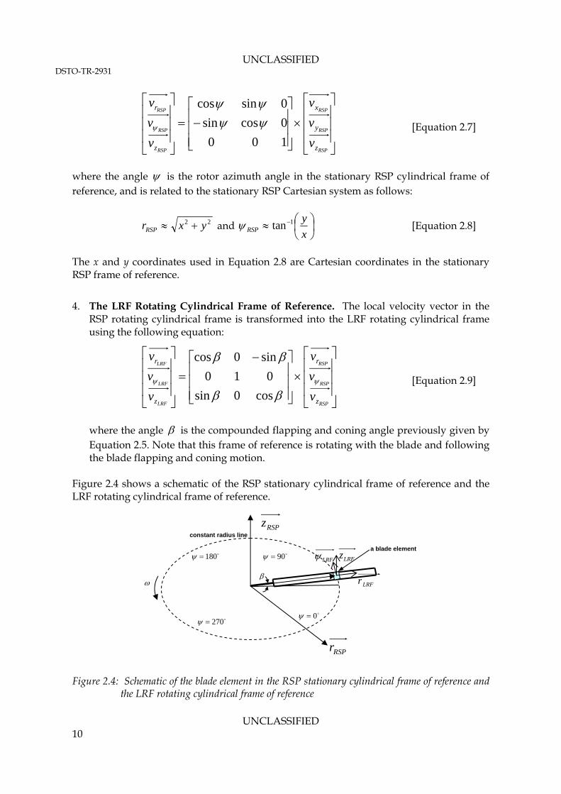
4. The LRF Rotating Cylindrical Frame of Reference. The local velocity vector in the RSP rotating cylindrical frame is transformed into the LRF rotating cylindrical frame using the following equation:
RSP
RSP
RSP
LRF
LRF
LRF
z
r
z
r
v
v
v
v
v
v
cos0sin
010
sin0cos
[Equation 2.9]
where the angle is the compounded flapping and coning angle previously given by Equation 2.5. Note that this frame of reference is rotating with the blade and following the blade flapping and coning motion.
Figure 2.4 shows a schematic of the RSP stationary cylindrical frame of reference and the LRF rotating cylindrical frame of reference.
Figure 2.4: Schematic of the blade element in the RSP stationary cylindrical frame of reference and
the LRF rotating cylindrical frame of reference
180
270
constant radius line
90
0
a blade element
RSPz
RSPr
LRFzLRF
LRFr

UNCLASSIFIED DSTO-TR-2931
UNCLASSIFIED 11
2.3.3 Blade Forces Calculation
A schematic of the blade element representation in the LRF rotating cylindrical frame of reference is shown at Figure 2.5. It is important to note that the coordinate system shown in this figure is already in the LRF rotating cylindrical frame of reference. The blade element area is given by:
).( rrA [Equation 2.10] Since the blade is not physically modelled in the VBM, each cell in the rotor disk region is assumed to represent a blade element. However, it is important to note that the computational cells in the disk mesh are in the RSP frame of reference, NOT in the LRF frame of reference. Each cell in the rotor disk region can be described by the radial position vector relative to
the disk origin, r (x,y,z) and the rotor azimuth angle, . As previously discussed in
Section 2.3.2(3), the vector r and azimuth angle are approximated using the Cartesian coordinates of each cell relative to the rotor disk centre in the mesh in the stationary RSP
frame of reference. The same vector r and azimuth angle have been used for the calculation of the force acting on each cell in the LRF frame of reference. Therefore, it is expected that some errors are introduced in the calculation due to this approximation. However, this error was deemed acceptably small when the RSP pitch and bank angles are small (typically less than five degrees), and when the compounded blade flap and cone angles are also small (typically less than five degrees).
Figure 2.5: Blade element
A schematic of the drag and lift forces acting on the blade element at any arbitrary coordinate in the LRF is shown in Figure 2.6.
0
90
a blade element
LRFr
LRF
LRFr
LRFLRFLRFr .

UNCLASSIFIED DSTO-TR-2931
UNCLASSIFIED 12
Figure 2.6: Schematic of the forces acting on the blade element in the LRF
LRFi is the induced AOA in the LRF, which is given by:
LRF
LRF
LRF v
vzi
'
tan 1 [Equation 2.11]
where LRFzv was previously calculated using Equation 2.9.
LRFv ' is the total relative fluid
velocity with respect to the blade tangential velocity, and is given by:
LRFrvvLRFLRF
' [Equation 2.12]
where the first term in Equation 2.12 refers to the local fluid velocity in the direction parallel to the blade path as previously given in Equation 2.9, and the second term refers to the blade linear velocity component in the direction parallel to the blade path. The velocity component acting on the blade element in the direction orthogonal to the blade path,
LRFzv is previously given by Equation 2.9.
To estimate the forces acting on fluid particles, consider the forces acting on the two-dimensional blade section shown in Figure 2.6. Note that the positive rotation of the airfoil is in the positive z-direction. Components of the blade force acting in the normal and tangential direction to the blade chord are given by the following equations:
LRFLRFLRF idilz fff sincos [Equation 2.13]
LRFLRFLRF idil fff cossin [Equation 2.14]
zero lift axis
lift,
drag,
lf
df
LRFzf
LRFf
LRFi
LRFiLRFe
LRFi
LRFg
LRFv' LRFzv

UNCLASSIFIED DSTO-TR-2931
UNCLASSIFIED 13
2.3.4 Blade Section Lift and Drag
The blade sectional lift, lf , and sectional drag, df , on each blade element (seen in
Equations 2.13 and 2.14) are calculated based on the effective AOA seen by the blade element and the airfoil lift and drag coefficients. From Figure 2.6, the effective AOA seen by each blade element (
LRFe ) is given by:
LRFLRFLRF ige [Equation 2.15]
Using the effective AOA, the sectional lift and drag coefficients can be obtained as a function of AOA using a predefined lookup table. The lookup tables are user inputs which can be obtained using the two-dimensional lifting line theory for a given blade airfoil shape. It is important to note that this model neglects any compressibility effect due to the moving blade. The blade lift coefficient is assumed to be directly proportional to the
effective AOA, i.e. LRFelC .
The sectional forces acting on the blade are given by:
llocall cCUf 2
2
1 [Equation 2.16]
dlocald cCUf 2
2
1 [Equation 2.17]
where: c is the chord length at the location of the blade element, lC and dC are the sectional lift and drag coefficient respectively, and
localU is the local induced fluid velocity experienced by the blade element.
The local velocity is given by the following expression for each blade element:
22 'LRFLRF
vvU zlocal [Equation 2.18]
The radial fluid velocity component in the rotor disk region has not been included in
Equation 2.18 in accordance to the BET assumption. LRFzv and
LRFv ' were previously
calculated using Equation 2.9 and Equation 2.12 respectively. The blade sectional lift and drag in Equations 2.16 and 2.17 can subsequently be substituted into Equations 2.13 and 2.14 to obtain the rotor thrust and torque forces which are the forces normal and parallel to the rotor disk plane respectively.

UNCLASSIFIED DSTO-TR-2931
UNCLASSIFIED 14
Finally the elemental thrust, torque, and power on each blade element can be calculated using:
drfNdTLRFzb [Equation 2.19]
rdrfNdQLRFb [Equation 2.20]
rdrfNdQdPLRFb . [Equation 2.21]
where bN is the number of blades in the rotor disk. The total forces on the rotor disk are
obtained by integrating over the blade span from root to tip. The root cutout can be modelled as a “hole” in the centre of the disk. 2.3.5 Blade Tip Effect
As previously discussed, at each spanwise location of the blade (which is equal to the radial direction of the rotor disk) local lift and drag forces are computed assuming two-dimensional flow. This assumption is violated in close proximity to the blade tip due to the presence of increasingly strong secondary flow around this area. To account for the loss of blade lift near the tip, a simple correction factor was applied to the force calculations in the region near the edge of the rotor disk. In the corrected model, the blade lift is assumed to be zero for blade elements that are located outward of a certain user-selected threshold value. This threshold is in the form of a radial distance from the rotor disk origin, normalised by the rotor disk radius. For example, a value of 0.96 means that from a normalized span of 0.96 outward, the lift forces are set to zero while the drag forces are still accounted for (using the two-dimensional assumption). Hence, using this example, the last four per cent of the blade span produces no lift (just recirculation around the blade) while it still produces drag. A tip loss factor of 0.96 is typical for a helicopter rotor (Reference 12). 2.3.6 Momentum Sources
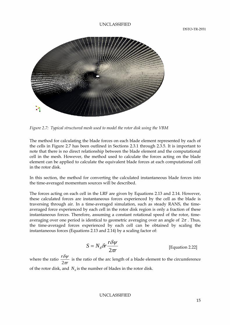
Figure 2.7 shows a typical structured mesh used for CFD modelling of a rotor disk using the VBM. The rotor disk is represented in the CFD model by a collection of cells (in this case of hexahedral form). In the VBM, momentum sources that represent the effect of the blade forces on the fluid flow are introduced in each of the computational cells in the rotor disk region.
UNCLASSIFIED DSTO-TR-2931
UNCLASSIFIED 15
Figure 2.7: Typical structured mesh used to model the rotor disk using the VBM
The method for calculating the blade forces on each blade element represented by each of the cells in Figure 2.7 has been outlined in Sections 2.3.1 through 2.3.5. It is important to note that there is no direct relationship between the blade element and the computational cell in the mesh. However, the method used to calculate the forces acting on the blade element can be applied to calculate the equivalent blade forces at each computational cell in the rotor disk. In this section, the method for converting the calculated instantaneous blade forces into the time-averaged momentum sources will be described. The forces acting on each cell in the LRF are given by Equations 2.13 and 2.14. However, these calculated forces are instantaneous forces experienced by the cell as the blade is traversing through air. In a time-averaged simulation, such as steady RANS, the time-averaged force experienced by each cell in the rotor disk region is only a fraction of these instantaneous forces. Therefore, assuming a constant rotational speed of the rotor, time-averaging over one period is identical to geometric averaging over an angle of 2 . Thus, the time-averaged forces experienced by each cell can be obtained by scaling the instantaneous forces (Equations 2.13 and 2.14) by a scaling factor of:
r
rrNS b 2
[Equation 2.22]
where the ratio r
r
2
is the ratio of the arc length of a blade element to the circumference
of the rotor disk, and bN is the number of blades in the rotor disk.

UNCLASSIFIED DSTO-TR-2931
UNCLASSIFIED 16
Applying the scaling factor in Equation 2.22 to the instantaneous forces given by Equations 2.13 and 2.14 yields the resultant time-averaged forces acting on each cell as:
r
rrNfSfF bzzz LRFLRFLRF
2
.. [Equation 2.23]
r
rrNfSfF bLRFLRFLRF
2
.. [Equation 2.24]
For a structured mesh in the rotor disk, the term rr. is equivalent to the blade element area A (refer to Equation 2.10). This assumption is only valid if the cell is of the form of a hexahedra, where the sides are parallel to the radial lines and the other two sides are lying on concentric circles. Therefore, the mean forces acting on each cell can be calculated as follows:
cell
cell
cellzb
cellzr
Af
NF
LRFLRF
2
[Equation 2.25]
cell
cell
cell
b
cell r
Af
NF
LRFLRF
2
[Equation 2.26]
This implementation limits the cell type that can be used for meshing the rotor disk region in the CFD model to only structured hexahedral cells. The forces on each cell given by Equations 2.25 and 2.26 are forces in the LRF rotating cylindrical frame of reference. Therefore, these forces need to be transformed back into the RSP rotating cylindrical frame of reference using the following operation:
LRF
LRF
LRF
RSP
RSP
RSP
z
r
z
r
F
F
F
F
F
F
cos0sin
010
sin0cos
[Equation 2.27]
Following this transformation, the forces in the rotor RSP rotating cylindrical frame of reference need to be transformed into the RSP stationary Cartesian frame of reference using the following equation:

UNCLASSIFIED DSTO-TR-2931
UNCLASSIFIED 17
RSP
RSP
RSP
RSP
RSP
RSP
z
r
z
y
x
F
F
F
F
F
F
100
0cossin
0sincos
[Equation 2.28]
The calculated forces in the RSP stationary Cartesian frame of reference can finally be transformed to the global Cartesian frame using the rotor disk pitch and bank angles as follows:
RSP
RSP
RSP
z
y
x
z
y
x
F
F
F
F
F
F
cossin0
sincos0
001
cos0sin
010
sin0cos
[Equation 2.29] Finally, the rotor forces in the global Cartesian frame can be converted into volumetric momentum sources on every cell in the rotor disk region by dividing the cell forces by the cell volume as follows:
cellcell
cellU FV
S 1
[Equation 2.30]
where cellF is the force vector in the global Cartesian frame at every cell in the rotor disk
region as given by Equation 2.29, and cellV is the cell volume.
2.3.7 Rotor Trim Model
According to Reference 4, accurate aerodynamic predictions are only possible if the rotors are operating at the correct thrust level. This means that a trimming computation is needed during the CFD simulation if the blade parameters necessary to achieve the correct thrust level are not known a priori. Furthermore, during a steady hover or level flight, the rotor moments are generally zero; hence, this must be accurately represented by the VBM during the simulation. At any arbitrary flight mode, the total thrust and rotor pitching and rolling moments acting on the rotor disk can be calculated by integrating the cell forces across the entire rotor disk region as follows:

UNCLASSIFIED DSTO-TR-2931
UNCLASSIFIED 18
nCell
iiRSPiii
nCell
iiRSPiii
nCell
iRSPi
roll
pitch
thrust
yrF
xrF
zF
M
M
F
1
1
1
.
.
.
[Equation 2.31]
The effect of flapping hinge offset is neglected from the moment calculations, shown in Equation 2.31. Since the relationship between the rotor aerodynamic parameters and the blade pitch is non-linear, an iterative technique is needed to obtain a converged trim result. In such a method, the collective and cyclic pitch angles are iteratively perturbed in the simulation in order to achieve the desired thrust coefficient, and eliminate the moments around the hub. The updates to the blade angles, which are treated as a control input at each trim iteration, can be obtained using a Newton-Raphson method applied to a linearised system of coupled equations relating the rotor response (i.e. the rotor thrust and moments) to the control vector.
Let the control input vector be denoted by x , and the rotor response vector be denoted by
y , as follows:
B
Axcollective
, and
roll
pitch
thrust
M
M
F
y
A first order Taylor expansion for the rotor response about x can then be written as:
... xJxyxxy [Equation 2.32]
where xxy is the rotor response vector due to the new control input vector xx . Equation 2.32 can then be re-arranged into:
xyxxyxJ [Equation 2.33] The tensor J is the Jacobian of the dependant quantities (response variables in terms of the control input (i.e. thrust, pitching and rolling moments), and is given by the following tensor:

UNCLASSIFIED DSTO-TR-2931
UNCLASSIFIED 19
B
M
A
MMB
M
A
MMB
F
A
FF
rollroll
collective
roll
pitchpitch
collective
pitch
thrustthrust
collective
thrust
[Equation 2.34]
Each term in the Jacobian tensor can be discretised using first order Taylor expansion for solving with the Newton-Raphson method. For example, the Jacobian for the thrust can be discretised into:
22
initthrustinitthrustthrust FFF [Equation 2.35]
Equation 2.35 is solved for an initial guess value of BAcollective ,, . Following the initial
solution a perturbed solution is obtained from the small perturbation angle of 2 . The iterations stop and an estimate for the changes to the perturbed angles
BAcollective ,, is obtained in the form of:
)1()0(
)0(
)0(
.
roll
pitch
thrustcollective
rollroll
collective
roll
pitchpitch
collective
pitch
thrustthrust
collective
thrust
roll
pitch
thrust
M
M
F
B
A
B
M
A
MMB
M
A
MMB
F
A
FF
M
M
F
[Equation 2.36]
Note that for this method to work the Jacobian must be constructed from a frozen flow-field and perturbing the pitch angles independently. With the new as the initial guess, the above iterative procedure continues until the target thrust and moments are achieved, and the flow-field is converged. 2.3.8 Dimensionless Parameters
It is sometimes convenient to specify the target thrust and moments acting on the rotor disk by using a set of dimensionless parameters. The following dimensionless parameters are commonly used to describe the rotor performance:
Coefficient of Thrust: 2diskdisk
thrustT
RA
FC
[Equation 2.37]

UNCLASSIFIED DSTO-TR-2931
UNCLASSIFIED 20
Coefficient of Pitching Moment: diskdiskdisk
pitchMx
RRA
MC
2 [Equation 2.38]
Coefficient of Rolling Moment: diskdiskdisk
rollMy
RRA
MC 2
[Equation 2.39]
In the current implementation, the rotor trim model utilises the total rotor thrust and moment values as the desired trim target. However, the dimensionless parameters are commonly used for specifying the desired rotor performance. Therefore, the target forces and moments must be calculated from the dimensionless parameters using Equations 2.37 through 2.39. 2.3.9 Summary
A VBM model for modelling the flow through a simplified rotor disk in a RANS simulation has been described in detail in this section. This model, which is derived from the well-known BET, accounts for the time-averaged effect of the motion of the blade in a rotor disk region embedded inside a larger computational domain used in CFD. The model introduces volumetric momentum sources in each computational cell that collectively make up the rotor disk region. The momentum sources are computed based on the time-averaged blade forces (per unit cell volume) imparted by the blade onto the fluid as it traverses through the air. The VBM also accounts for the blade flapping and coning. Furthermore, the blade collective pitch, cyclic pitch, and twist angles are mathematically modelled in the VBM. The model description presented in this section will form the basis of its implementation in OpenFOAM, which will be presented in Section 3.

UNCLASSIFIED DSTO-TR-2931
UNCLASSIFIED 21
3. Model Implementation in OpenFOAM
3.1 Overview
This section describes the specific implementation of the VBM in the OpenFOAM environment. The description contained in this Section will focus on providing the reader with an overview of the code structure, as well as the integration of the VBM with the flow solver in OpenFOAM. A complete copy of the code is provided at Appendix A. As previously described in Section 2, the VBM essentially introduces momentum sources in the cells that collectively make up the rotor disk region. Therefore, the description of the implementation of this model in OpenFOAM will begin by describing how these additional momentum sources are incorporated into the global fluid momentum equations that are solved by the RANS solvers. Following this, a detailed explanation of the object-orientation structure used in the VBM will be presented. A procedure on how to compile the code in the OpenFOAM environment will be given at the end of this Section. In order to understand the way in which the OpenFOAM library and solvers work, some background knowledge of C++, the base language of OpenFOAM, is required. A description of the C++ language, the object-oriented programming paradigm, and its best practice are outside the scope of this report. However, the OpenFOAM User Guide (Reference 13) and Programming Guide (Reference 14) provide a good overview of the general code structure, the use of object-orientation paradigm in OpenFOAM, and several base classes and operators used in OpenFOAM. The description contained in this Section of the report shall assume that the reader has some familiarity with the C++ object-oriented paradigm, but minimal knowledge of the OpenFOAM classes and solvers. 3.2 Applicable OpenFOAM Version
OpenFOAM is continuously updated through the use of its online repository at Reference 3. The final version of the code developed in this report was ensured to be fully compatible with OpenFOAM version 2.1.x (dated 26 June 2012). Consequently, all OpenFOAM code described in this report refers to the aforementioned version release. Due to potential changes implemented in the base OpenFOAM code between version updates, the VBM code delivered in this report may not compile or run with the later version. However, to an experienced OpenFOAM user, relatively minor changes can be implemented in the current VBM code to make it compatible with the later releases of OpenFOAM. Similarly, the VBM code delivered in this report is not guaranteed to be compatible with any OpenFOAM versions earlier than the version 2.1.x (dated 26 June 2012).

UNCLASSIFIED DSTO-TR-2931
UNCLASSIFIED 22
3.3 The Flow Solvers
3.3.1 Overview of RANS Solvers in OpenFOAM
The standard OpenFOAM distribution includes a collection of top-level flow solvers. These flow solvers are the top-most level executable files in OpenFOAM, and are differentiated based on the flow physics that are being solved. Table 3.1 provides a set of examples of the variety of OpenFOAM standard solvers that are typically used in the IRSA group. Note that the standard OpenFOAM distribution includes a larger number of standard solvers than that shown in Table 3.1. Table 3.1: List of standard OpenFOAM flow solvers that are applicable to the IRSA Group
Basic' CFD Solver
laplacianFoamSolves a simple Laplace equation, e.g. for thermal diffusionin a solid
potentialFoamSimple potential flow solver which can be used to generatestarting fields for full Navier-Stokes codes
Incompressible Flow Solvers
boundaryFoamSteady-state solver for incompressible, 1D turbulent flow, typically to generate boundary layer conditions at an inlet, for use in a simulation
icoFoamTransient solver for incompressible, laminar flow of Newtonianfluids
simpleFoamSteady-state solver for incompressible, turbulent flow based on SIMPLE algorithm
SRFSimpleFoamSteady-state solver for incompressible, turbulent flow of non-Newtonian fluids in a single rotating frame
pisoFoam Transient solver for incompressible flow based on PISO algorithm
Compressible Flow SolversrhoSimpleFoam simpleFoam solver for compressible flow
rhoSimplecFoamSteady-state SIMPLEC solver for laminar or turbulent RANSflow of compressible fluids
rhoPimpleFoamLarge time-step transient solver for compressible flow usingthe PIMPLE (merged PISO-SIMPLE) algorithm
rhoCentralFoamDensity-based compressible flow solver based on central upwind schemes of Kurganov and Tadmor
Heat Transfer and Buoyancy Driven Flow Solvers
buoyantBaffleSimpleFoamSteady-state solver for buoyant, turbulent flow of compressiblefluids using thermal baffles
buoyantBoussinesqSimpleFoamSteady-state solver for buoyant, turbulent flow of incompressible fluids based on SIMPLE algorithm and Boussinesq approximation
buoyantSimpleFoamSteady-state solver for buoyant, turbulent flow of compressible fluids based on SIMPLE algorithm
Combustion
rhoReactingFoamSolver for combustion with chemical reactions using densitybased thermodynamics package
fireFoam Transient Solver for Fires and turbulent diffusion flames
PDRFoamSolver for compressible premixed/partially-premixed combustion with turbulence modelling
dieselEngineFoam Solver for diesel engine spray and combustion
The VBM code was developed to be compatible with any of the above listed flow solvers. However, further modification to the standard flow solvers may be needed to implement the VBM model in the solvers.

UNCLASSIFIED DSTO-TR-2931
UNCLASSIFIED 23
In this report, an example of how one may modify the off-the-shelf steady-state compressible flow solver, rhoSimpleFoam, to include the VBM calculation in the simulation will be provided. However, the same procedure can be applied to any of the above listed flow solvers. 3.3.2 Overview of the rhoSimpleFoam Solver
The standard rhoSimpleFoam source code can be found in the following path: $FOAM_APPLICATIONS/solvers/compressible/rhoSimpleFoam rhoSimpleFoam, like any other flow solver in OpenFOAM, is largely procedural since it is a close representation of solution algorithms and equations, which are procedural in nature (Reference 13). Therefore, users do not necessarily need a deep knowledge of object-oriented paradigm and C++ programming to write a solver but should know the principles behind object-oriented paradigm and classes, and to have a basic knowledge of some C++ code syntax. An understanding of the underlying equations, models and solution method and algorithms is deemed to be far more important in developing new flow solvers in OpenFOAM. The main implementation of rhoSimpleFoam is contained in the file rhoSimpleFoam.C. As the name implies, the solution algorithm is based on the Semi-Implicit Pressure-Linked Equation (SIMPLE) algorithm (Reference 13) which is shown graphically in Figure 3.1. As shown in Figure 3.1, the algorithm basically consists of:
1. assembling of the discretised momentum equations into a matrix,
2. solving the momentum equations by first treating the pressure gradient term explicitly,
3. solving the pressure equation based on the computed momentum field, and
4. computing the pressure-corrected momentum field for the next flow iteration.
In this implementation, the additional momentum sources that are introduced by the VBM will be incorporated explicitly into the momentum matrix . The assembling of the momentum matrix is contained in the file UEqn.H which is reproduced in Figure 3.2. The momentum matrix, UEqn, assembled in the code in Figure 3.2 incorporates both the convective term and diffusive terms in the momentum equation; however, no source terms are present in the above code.

UNCLASSIFIED DSTO-TR-2931
UNCLASSIFIED 24
Figure 3.1: Implementation of the SIMPLE algorithm in rhoSimpleFoam
Figure 3.2: UEqn.H in rhoSimpleFoam
In OpenFOAM, there already a C++ class exists that allows generic source terms to be added to the momentum equation. This class is called “basicSource” class, and its source code lives in the following path $FOAM_SRC/finiteVolume/cfdTools/general/fieldSources/basicSources The class constructor to the basicSources class will be described later in Section 3.3.4. However, it is useful to know at this stage that the UEqn.H can be modified as shown in Figure 3.3 to incorporate a source term in the momentum equation. Furthermore, it is equally important to note at this stage that the basicSource class is an “abstract class”, which means it contains no specific implementation of the source terms that are to be introduced in the momentum equation. This specific implementation will be derived from the VBM implementation as described in Section 3.3.5.
// Solve the Momentum Equation tmp<fvVectorMatrix> UEqn ( fvm::div(phi, U) + turbulence->divDevRhoReff(U) ); UEqn().relax(); solve(UEqn() == -fvc::grad(p));
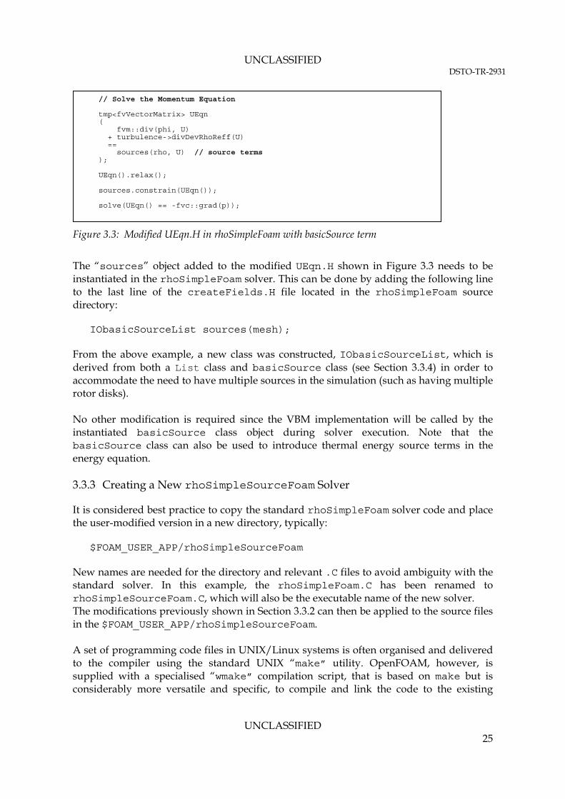
UNCLASSIFIED DSTO-TR-2931
UNCLASSIFIED 25
Figure 3.3: Modified UEqn.H in rhoSimpleFoam with basicSource term
The “sources” object added to the modified UEqn.H shown in Figure 3.3 needs to be instantiated in the rhoSimpleFoam solver. This can be done by adding the following line to the last line of the createFields.H file located in the rhoSimpleFoam source directory: IObasicSourceList sources(mesh); From the above example, a new class was constructed, IObasicSourceList, which is derived from both a List class and basicSource class (see Section 3.3.4) in order to accommodate the need to have multiple sources in the simulation (such as having multiple rotor disks). No other modification is required since the VBM implementation will be called by the instantiated basicSource class object during solver execution. Note that the basicSource class can also be used to introduce thermal energy source terms in the energy equation. 3.3.3 Creating a New rhoSimpleSourceFoam Solver
It is considered best practice to copy the standard rhoSimpleFoam solver code and place the user-modified version in a new directory, typically: $FOAM_USER_APP/rhoSimpleSourceFoam New names are needed for the directory and relevant .C files to avoid ambiguity with the standard solver. In this example, the rhoSimpleFoam.C has been renamed to rhoSimpleSourceFoam.C, which will also be the executable name of the new solver. The modifications previously shown in Section 3.3.2 can then be applied to the source files in the $FOAM_USER_APP/rhoSimpleSourceFoam. A set of programming code files in UNIX/Linux systems is often organised and delivered to the compiler using the standard UNIX “make” utility. OpenFOAM, however, is supplied with a specialised “wmake” compilation script, that is based on make but is considerably more versatile and specific, to compile and link the code to the existing
// Solve the Momentum Equation tmp<fvVectorMatrix> UEqn ( fvm::div(phi, U) + turbulence->divDevRhoReff(U) == sources(rho, U) // source terms ); UEqn().relax(); sources.constrain(UEqn()); solve(UEqn() == -fvc::grad(p));

UNCLASSIFIED DSTO-TR-2931
UNCLASSIFIED 26
OpenFOAM library. The process of compiling a new code or library in OpenFOAM using the wmake script is given at Reference 14. OpenFOAM applications are organised using a standard convention that requires the source code of each application to be placed in a directory whose name is that of the application. The top level source file takes the application name with the .C extension. This convention must be adhered to when creating new solvers or applications in OpenFOAM. For example, the source code for the newly created rhoSimpleSourceFoam solver would reside in a directory rhoSimpleSourceFoam and the top level file would be rhoSimpleSourceFoam.C as shown in Figure 3.4. The directory must also contain a “Make” sub-directory containing two files, “options” and “files”.
Figure 3.4: Directory structure for an application in OpenFOAM
The final step that needs to be done prior to compiling the new solver, rhoSimpleSourceFoam, is to modify the Make/files and Make/options to include the entries shown in Figure 3.5.
Figure 3.5: Modified Make/files and Make/options for compiling rhoSimpleSourceFoam
$ cat Make/files rhoSimpleSourceFoam.C EXE = $(FOAM_USER_APPBIN)/rhoSimpleSourceFoam // The EXE variable determines where the new executable binary will be // placed. It is important to use $(FOAM_USER_APPBIN) path instead of // the standard $(FOAM_APPBIN) for revision control. $ cat Make/options EXE_INC = \ -I$(LIB_SRC)/thermophysicalModels/basic/lnInclude \ -I$(LIB_SRC)/turbulenceModels \ -I$(LIB_SRC)/turbulenceModels/compressible/RAS/RASModel \ -I$(LIB_SRC)/finiteVolume/cfdTools \ -I$(LIB_SRC)/finiteVolume/lnInclude \ -I$(LIB_SRC)/meshTools/lnInclude EXE_LIBS = \ -lbasicThermophysicalModels \ -lspecie \ -lcompressibleTurbulenceModel \ -lcompressibleRASModels \ -lfiniteVolume \ -lmeshTools
$FOAM_USER_APP/rhoSimpleSourceFoam
rhoSimpleSourceFoam.C
HeaderFiles.H
Make
files
options

UNCLASSIFIED DSTO-TR-2931
UNCLASSIFIED 27
Finally the new rhoSimpleSourceFoam solver can be compiled by executing wmake from the code parent directory using the following commands: $ cd $FOAM_USER_APP/rhoSimpleSourceFoam $ wmake 3.3.4 The basicSource Class
The momentum sources introduced by the VBM will be implemented in the flow solver through the use of the class basicSource. Therefore, before the newly developed VBM model can be introduced, it is important for the reader to first understand the implementation of the basicSource class in OpenFOAM.
Figure 3.6: Class hierarchy of basicSource class in OpenFOAM
Figure 3.6 shows the basicSource class hierarchy. The hierarchy diagram has been generated using doxygen. Further details on doxygen legend can be found at Reference 15. As seen from this figure, the VBM code will be implemented as a new class, called “rotorDiskSource”, which will inherit attributes from the basicSource class. Since the basicSource class is an abstract class with no implementation (by using virtual functions), the implementation of the VBM using this class in the flow solver can be made by adding the VBM libraries into the runTimeSelectionTable of this class. This means that the rotorDiskSource class (and all other classes derived from the rotorDiskSource class) that contains the specific implementation of the VBM will contain a series of functions that can be “hooked-up” with the virtual functions in the
rotorDiskSource The new class containing the implementation of the VBM in OpenFOAM.

UNCLASSIFIED DSTO-TR-2931
UNCLASSIFIED 28
basicSource class. Virtual functions that are used in the implementation of the rotorDiskSource class are listed below:
virtual void isActive(). This virtual function reads the input dictionary of the source model and determines if the source is active during a simulation.
virtual bool read (const dictionary &dict). This virtual function reads the input dictionary of the source model for relevant parameters to be used in the model implementation.
virtual void addSup(fvMatrix<type> &UEqn, const label fieldI). This virtual function adds the momentum sources explicitly into the passed momentum matrix.
Interested users and readers are recommended to further explore the functionality provided by the basicSource class by reviewing its source code. One of the major advantages of using the basicSource class as a template abstract class for deriving the VBM library is that multiple source term objects of different kind can be spawned in the simulation. This means that the simulation can include multiple rotor disks, multiple heat source terms, and multiple porosity terms. The basicSource class is a registeredIOObject class, which means any basicSource object spawned during runtime is automatically tracked globally by the solver. However, since the basicSource class is an abstract class, the specific implementation of the source term (e.g. VBM or heat source term) can vary depending on the specific classes that are derived from this basicSource class. Some examples of such derived classes are rotorDiskSource (VBM), actuationDiskSource (momentum sink) and porousMedia (porosity momentum sink). 3.3.5 Overview of the VBM Library Classes
The VBM code developed in OpenFOAM comprises multiple C++ classes. The file structure grouped by the class name is shown in Figure 3.7. Calculation of the blade forces and momentum source terms using the methodology outlined in Section 2 is implemented in the main class, rotorDiskSource. A hard copy of all the source code included in Figure 3.7 is available from Appendix A, sorted by the class hierarchy.

UNCLASSIFIED DSTO-TR-2931
UNCLASSIFIED 29
Figure 3.7: Overview of the directory and file structure of the VBM source code in OpenFOAM
As previously discussed, the rotorDiskSource class must inherit from the abstract base class basicSource in order to be implemented in the flow solvers. This is reflected in the file rotorDiskSource.H (Appendix A.2.1), which includes the class declaration statement shown in Figure 3.8. The rotorDiskSource.H also contains a declaration for the class constructor function, all private and public data members, as well as all the private and public member functions of the rotorDiskSource class. It is important to note that because this class inherits from the basicSource class, any change in the
[rotorDiskSource] | |---- [Make] | |---- files | \---- options | |---- [bladeModel] | |---- bladeModel.C | \---- bladeModel.H | |----- [profileModel] | | | |---- [lookup] | | |---- lookupProfile.C | | \---- lookupProfile.H | | | |---- profileModel.C | |---- profileModel.H | |---- profileModelList.C | |---- profileModelList.H | | | \---- [series] | |---- seriesProfile.C | \---- seriesProfile.H | |---- rotorDiskSource.C |---- rotorDiskSource.H |---- rotorDiskSourceI.H |---- rotorDiskSourceTemplates.C | \----- [trimModel] | |---- [fixed] | |---- fixedTrim.C | \---- fixedTrim.H | |---- [targetForce] | |---- targetForceTrim.C | \---- targetForceTrim.H | \---- [trimModel] |---- trimModel.C |---- trimModel.H \---- trimModelNew.C
The main class for the VBM implementation. This class inherits from the basicSource class.
An abstract class for different methods of constructing the Cl and Cd lookup tables. It allows for easy addition of new methods of constructing the blade Cl and Cd curves. The class “lookup” inherits from profileModel and uses linear interpolation to construct the Cl andCd curves. The class “series” inherits from profileModel and uses a harmonic function to construct the Cl and Cd curves.
A class for constructing the blade geometrical angle of attack as a function of the disk radial and azimuthal positions.
An abstract class for different rotor trim models. It allows for easy addition of new trim models.
Classes that inherit from the abstract class trimModel, and contain different implementations of the rotor trim model, i.e.
- fixed: No trimming - targetForce: Perturb the blade AOA to
achieve the user specified target forces and moments

UNCLASSIFIED DSTO-TR-2931
UNCLASSIFIED 30
constructor of the basicSource class in a later release of OpenFOAM must also be propagated to this class.
Figure 3.8: Class declaration in rotorDiskSource.H showing inheritance from basicSource
In order for the rotorDiskSource class to “hook-up” with the basicSource class, the following two criteria must be satisfied:
1. The class must contain implementations of the basicSource class virtual functions listed in previously in Section 3.3.4, and
2. The class must inherit from the basicSource class, have a specific typeName, and contain an implementation that allows for the class to be registered in the runTimeSelectionTable of the basicSource class.
The implementation of the two criteria above in the rotorDiskSource will be discussed in the following paragraphs. Implementation of the basicSource virtual functions in rotorDiskSource. The implementation of the virtual function addSup() which returns the momentum sources to the flow solvers is shown in Figure 3.9. Note that the addSup() in the rotorDiskSource actually calls another protected internal member function calculate() included in the rotorDiskSource. Similarly, the implementation of the virtual functions read() and writeData() can also be found in the rotorDiskSource.C. Adding the rotorDiskSource class to the runTimeSelectionTable. The basicSource is an abstract class that allows for new source models to be introduced and registered to its runTimeSelectionTable. This mechanism allows the user to select the different source models to be run with the flow solvers without re-compiling the entire base code prior to each run. In the case of the rotorDiskSource, this process is done using a static member function in the rotorDiskSource.C as shown in Figure 3.10. Note that this process is generic in OpenFOAM, and can be copied for adding any new source models or boundary conditions in the future.
$cat rotorDiskSource.H class rotorDiskSource : public basicSource {
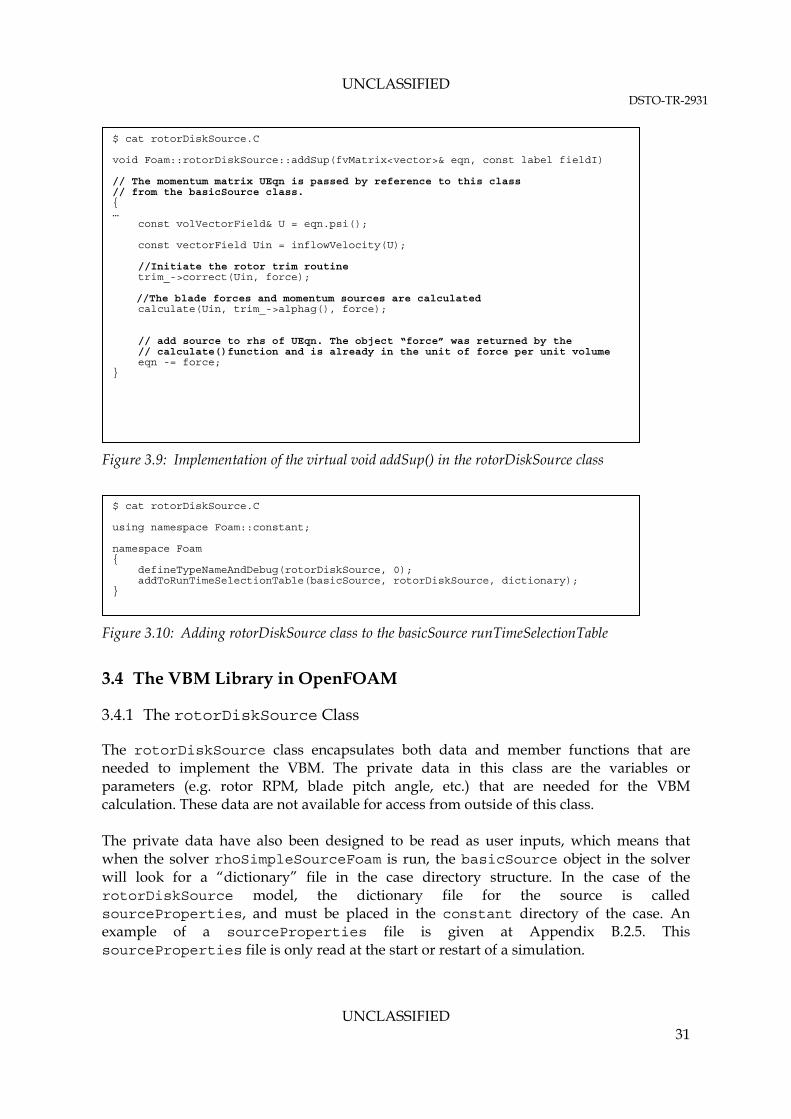
UNCLASSIFIED DSTO-TR-2931
UNCLASSIFIED 31
Figure 3.9: Implementation of the virtual void addSup() in the rotorDiskSource class
Figure 3.10: Adding rotorDiskSource class to the basicSource runTimeSelectionTable
3.4 The VBM Library in OpenFOAM
3.4.1 The rotorDiskSource Class
The rotorDiskSource class encapsulates both data and member functions that are needed to implement the VBM. The private data in this class are the variables or parameters (e.g. rotor RPM, blade pitch angle, etc.) that are needed for the VBM calculation. These data are not available for access from outside of this class. The private data have also been designed to be read as user inputs, which means that when the solver rhoSimpleSourceFoam is run, the basicSource object in the solver will look for a “dictionary” file in the case directory structure. In the case of the rotorDiskSource model, the dictionary file for the source is called sourceProperties, and must be placed in the constant directory of the case. An example of a sourceProperties file is given at Appendix B.2.5. This sourceProperties file is only read at the start or restart of a simulation.
$ cat rotorDiskSource.C using namespace Foam::constant; namespace Foam { defineTypeNameAndDebug(rotorDiskSource, 0); addToRunTimeSelectionTable(basicSource, rotorDiskSource, dictionary); }
$ cat rotorDiskSource.C void Foam::rotorDiskSource::addSup(fvMatrix<vector>& eqn, const label fieldI) // The momentum matrix UEqn is passed by reference to this class // from the basicSource class. { … const volVectorField& U = eqn.psi(); const vectorField Uin = inflowVelocity(U); //Initiate the rotor trim routine trim_->correct(Uin, force); //The blade forces and momentum sources are calculated calculate(Uin, trim_->alphag(), force); // add source to rhs of UEqn. The object “force” was returned by the // calculate()function and is already in the unit of force per unit volume eqn -= force; }

UNCLASSIFIED DSTO-TR-2931
UNCLASSIFIED 32
A flowchart showing the implementation of the rotorDiskSource class in the OpenFOAM rhoSimpleSourceFoam solver is shown in Figure 3.11. However, the rotorDiskSource class has been written as a generic class that can readily be implemented in any of the other OpenFOAM flow solvers (previously listed in Table 3.1) by following the method previously outlined in Sections 3.3.2 through 3.3.3. The class declaration and definition for rotorDiskSource is given in the rotorDiskSource.H. The main implementation of the class is given in the rotorDiskSource.C. The bulk implementation of the BET is given in the Foam::rotorDiskSource::calculate() function in rotorDiskSource.C. A notable feature in the code structure is that calculation of the local blade geometric AOA is not implemented inside the rotorDiskSource class, but in a separate trimModel class (refer to Figure 3.13). This allows the future addition of a new trim model while avoiding significant re-structure of the rotorDiskSource class. Further description of the trimModel class will be given in Section 3.4.3. Other features of the rotorDiskSource class that allow for ease of future expansion are as follows:
1. Addition of new Lifting Line Models (in profileModel class). Currently two different models are implemented, i.e:
a. using a Lookup Table (profileModel::lookupProfile class), and
b. using Fourier Series (profileModel::seriesProfile class). The series definition is hard-coded in the seriesProfile.C file, and is defined by the following series equation:
n
ieffilL iCC
1
sin [Equation 3.1]
n
ieffiDD iCC
1
cos
2. Addition of new blade geometric models (in bladeModel class). Currently the blade can only be tapered linearly (i.e. the blade chord varies linearly with the cell radial distance from the rotor disk origin). The model also accommodates multiple taper angles along the blade radius. Future blade models may allow the variation of the blade chord along the radius to be described using a more complex function.

UNCLASSIFIED DSTO-TR-2931
UNCLASSIFIED 33
Figure 3.11: Implementation of the VBM using rotorDiskSource class and rhoSimpleSourceFoam
solver in OpenFOAM
START
INIT MESH AND FLUX FIELD
SOLVE MOMENTUM EQN USING EXPLICIT
PRESSURE
<SIMPLE> SOLVE
PRESSURE EQN
CORRECT VELOCITY USING
PRESSURE
SOLVE TURBULENCE MODEL EQNS
ADD SOURCE TERM
<basicSource>
CONVERGED?
END
INIT ROTOR OBJECT <rotorDiskSource>
Mesh information, current velocity field
CALCULATE EFFECTIVE AOA ON
EACH CELL
CALCULATE LOCAL THRUST AND DRAG
<Blade Element Theory>
CONVERT BODY FORCES TO VOLUMETRIC
MOMENTUM SOURCE
INIT BLADE TRIM MODEL
<trimModel>
INIT BLADE LIFTING LINE MODEL
<profileModel>
TRIM CONVERGED
?
CALCULATE GLOBAL ROTOR DISK MOMENTS
AND THRUST
CALCULATE BLADE GEOMETRIC AOA
<bladeModel>
CALCULATE LOCAL INFLOW ANGLE
CALCULATE FLAPPING
BLADE TRIMMING LOOP:Perturb blade cyclic and collective pitch angles
Calculation in the Local Rotor Disk Cyclindrical Coordinate
READ sourceProperties
rotorDiskSource Class rhoSimpleSourceFoam Solver
YES
YES
NO
NO
Momentum sources are returned in the Global Cartesian Frame
Helper Classes
WRITE ROTOR FORCE [volVectorField]
IOObject NO_READ AUTO WRITE
NOTE: 1. Shaded boxes indicate separate classes
Return local blade geometric AOA
Return lift and drag lookup database
SOLVER SIMPLE ITERATION

UNCLASSIFIED DSTO-TR-2931
UNCLASSIFIED 34
3.4.2 The rotorDiskSource Input/Output (IO)
In the current implementation, the user must specify the rotor characteristics as input using the sourceProperties (Appendix B.2.5) file, which must be placed in the constant directory of each case. This file is read during the class construction by the function Foam::rotorDiskSource::read(). Any changes made by user to the sourceProperties file will be monitored and effected continuously during runtime at each iteration. The rotorDiskSource output consists of the following:
1. Field variable data output. In the current implementation, the lift and drag forces per unit cell volume are written out for post-processing as a vector field data type. The body forces can be visualised using paraview using a similar filter to that used to visualise the velocity field.
2. RunTime console output. In the current implementation, the rotor disk global pitching and rolling moments, and the total thrust is printed to the screen of the running Linux shell. An example of this output is given in Figure 3.12.
Additional data quantities, such as cell inflow angle, the cell’s cylindrical coordinate, and the cell’s effective AOA, can be written out using the provided templated function Foam::RotorDiskSource::writeField(), which is implemented in the source file rotorDiskSourceTemplates.C.
Figure 3.12: Linux shell output of rotorDiskSource during runtime

UNCLASSIFIED DSTO-TR-2931
UNCLASSIFIED 35
3.4.3 The Rotor trimModel Class
The trimModel class is an abstract class that carries out the blade trimming calculation required by the rotorDiskSource. The trimModel class is not derived from the rotorDiskSource. A private object called “trim_” of class type trimModel is instantiated inside the rotorDiskSource class during its construction. This trim_ object acts as the conduit between the trimming routine and the rotorDiskSource class during the calculation of the rotor forces. The implementation of the trimModel as an abstract class allows for different trim models to be added in the future without needing to alter any other part of the code. Currently, two classes are derived from the trimModel, which are user-selectable from the sourceProperties file. The two sub-classes provide two different trimming algorithms, as described below:
1. trimModel::fixedTrim class. The fixedTrim calculates the compounded blade geometric AOA variation with respect to cell radial and azimuthal position based on constant blade collective pitch angles and cyclic pitch coefficients. These coefficients must be provided by the user in the sourceProperties file. The use of this class is equivalent to an “untrimmed” VBM model.
2. trimModel::targetForceTrim class. The targetForceTrim class perturbs the local blade geometric AOA at a frozen flow state (at each flow solver iteration) to find a combination of blade collective pitch angles and cyclic pitch coefficients that will return the global thrust and moments on the rotor disk that match the user-specified target rotor thrust and moments. To use this trim model, the following parameters must be specified in the sourceProperties file:
a. The target global rotor thrust, rolling and pitching moments.
b. The initial guess of the blade collective pitch angle and cyclic pitch coefficients (refer to Equation 2.4).
c. The interval (in flow iterations) in-between trimming routines.
d. The angles by which the local blade AOA needs to be perturbed during trimming. The default value is 0.05 degree.
e. The under-relaxation factor for the newly calculated AOA during trimming. Note that this factor should be kept at one unless the trimming routine is unable to find a trimmed solution within its iteration limits.
The maximum number of iterations, and the minimum force and moments residuals allowed during trimming before a solution is deemed converged (or fully trimmed) are not user-specifiable. Currently, these are set to default values of 50 and 1x10⁻⁸ for the maxIter and residuals tolerance respectively. These values are hard-coded in the constructor function of the trimModel::targetForceTrim class, which can be found in the targetForceTrim.C file.
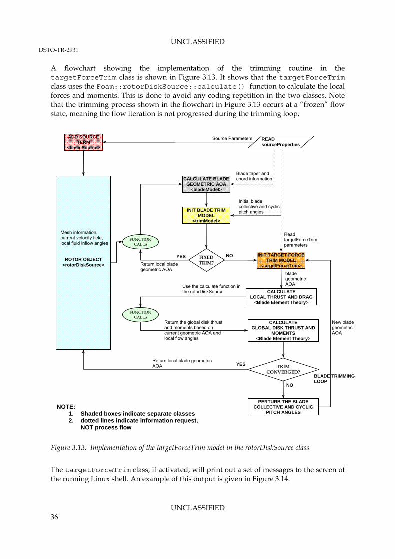
UNCLASSIFIED DSTO-TR-2931
UNCLASSIFIED 36
A flowchart showing the implementation of the trimming routine in the targetForceTrim class is shown in Figure 3.13. It shows that the targetForceTrim class uses the Foam::rotorDiskSource::calculate() function to calculate the local forces and moments. This is done to avoid any coding repetition in the two classes. Note that the trimming process shown in the flowchart in Figure 3.13 occurs at a “frozen” flow state, meaning the flow iteration is not progressed during the trimming loop.
Figure 3.13: Implementation of the targetForceTrim model in the rotorDiskSource class
The targetForceTrim class, if activated, will print out a set of messages to the screen of the running Linux shell. An example of this output is given in Figure 3.14.
ADD SOURCE TERM
<basicSource>
ROTOR OBJECT <rotorDiskSource>
INIT BLADE TRIM MODEL
<trimModel>
CALCULATE BLADE GEOMETRIC AOA
<bladeModel>
READ sourceProperties
Mesh information, current velocity field, local fluid inflow angles
Initial blade collective and cyclic pitch angles
Blade taper and chord information
Source Parameters
FIXED TRIM?
FUNCTION CALLS
YES INIT TARGET FORCE TRIM MODEL
<targetForceTrim>
NO
Return local blade geometric AOA
CALCULATE LOCAL THRUST AND DRAG
<Blade Element Theory>
Read targetForceTrim parameters
FUNCTION CALLS
Use the calculate function in the rotorDiskSource
blade geometric AOA
CALCULATE GLOBAL DISK THRUST AND
MOMENTS <Blade Element Theory>
TRIM CONVERGED?
PERTURB THE BLADE COLLECTIVE AND CYCLIC
PITCH ANGLES
New blade geometric AOA
Return the global disk thrust and moments based on current geometric AOA and local flow angles
Return local blade geometric AOA YES
NO
NOTE: 1. Shaded boxes indicate separate classes 2. dotted lines indicate information request,
NOT process flow
BLADE TRIMMING LOOP

UNCLASSIFIED DSTO-TR-2931
UNCLASSIFIED 37
Figure 3.14: Linux shell output of targetForceTrim class during runtime
3.5 Compiling the Code
The steps required to compile rotorDiskSource as a non-executable library in OpenFOAM differs to that required to compile an executable solver (e.g. rhoSimpleSourceFoam). A set of instructions on how to compile the rotorDiskSource will be given in the following paragraphs. 3.5.1 Preparation
Prior to code compilation, all the VBM library source codes (previously shown in Figure 3.7) can be placed at any location on the machine while maintaining the directory structure and naming; however, it is recommended that the source codes are placed at the following standard path, which is separate from the standard OpenFOAM source codes:
New blade pitch to be used in the next flow iteration (collective and cyclic)

UNCLASSIFIED DSTO-TR-2931
UNCLASSIFIED 38
${WM_PROJECT_USER_DIR}/lib It is considered a good practice to keep any third-party code separates from the standard OpenFOAM library. Linking the VBM library to the standard OpenFOAM library will be done during compilation. The code compilation must be done from inside the rotorDiskSource directory. The first step of the compilation involves cleaning the directory from any previous compilation artefacts, such as any “.o” or “.dep” files. This can be done as follows: $ cd ${WM_PROJECT_USER_DIR}/lib/rotorDiskSource $ rmdepall; wclean 3.5.2 Linking the VBM Library to the Standard OpenFOAM Libraries
By default, the compiler links to shared object library files in the following directory paths, which are specified with the -L option in the wmake:
1. The ${FOAM_LIBBIN} path;
2. Platform dependent paths set in files in the ${WM_DIR}/rules/${WM_ARCH} directory, e.g./usr/X11/lib and ${MPICH_ARCH_PATH}/lib;
3. Other directories specified in the Make/options file.
It is considered standard practice for any third-party object files or executables be placed in the ${FOAM_USER_LIBBIN}, which is separate from the standard OpenFOAM installation path. The ${FOAM_USER_LIBBIN} is a standard OpenFOAM environment variable set during installation. However, the user must check if ${FOAM_USER_LIBBIN} is valid on their OpenFOAM installation. This can be done using the standard utility foamInstallationTest. The library files to be linked must be specified using the -l option and removing the lib prefix and “.so” extension from the library file name, e.g. libbasicThermophysicalModels.so is included with the flag -lbasicThermophysicalModels. By default, wmake loads the following libraries for any third-party code compilation:
1. The libOpenFOAM.so library from the ${FOAM_LIBBIN} directory;
2. Platform dependent libraries specified in set in files in the ${WM_DIR}/rules/${WM_ARCH} , e.g. /usr/X11/lib/libm.so and ${LAM_ARCH_PATH}/lib/liblam.so;
3. Other libraries specified in the Make/options file. The following standard OpenFOAM libraries must also be linked during compilation of the rotorDiskSource:
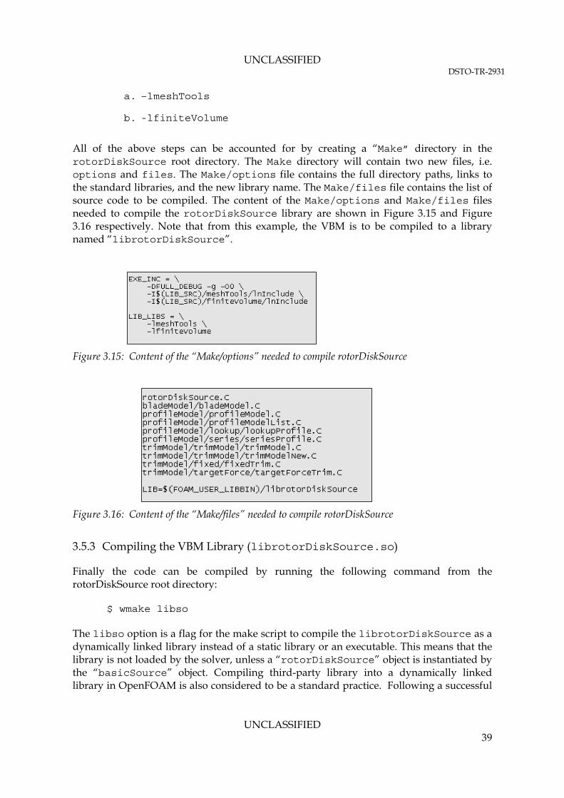
UNCLASSIFIED DSTO-TR-2931
UNCLASSIFIED 39
a. –lmeshTools
b. -lfiniteVolume
All of the above steps can be accounted for by creating a “Make” directory in the rotorDiskSource root directory. The Make directory will contain two new files, i.e. options and files. The Make/options file contains the full directory paths, links to the standard libraries, and the new library name. The Make/files file contains the list of source code to be compiled. The content of the Make/options and Make/files files needed to compile the rotorDiskSource library are shown in Figure 3.15 and Figure 3.16 respectively. Note that from this example, the VBM is to be compiled to a library named “librotorDiskSource”.
Figure 3.15: Content of the “Make/options” needed to compile rotorDiskSource
Figure 3.16: Content of the “Make/files” needed to compile rotorDiskSource
3.5.3 Compiling the VBM Library (librotorDiskSource.so)
Finally the code can be compiled by running the following command from the rotorDiskSource root directory: $ wmake libso The libso option is a flag for the make script to compile the librotorDiskSource as a dynamically linked library instead of a static library or an executable. This means that the library is not loaded by the solver, unless a “rotorDiskSource” object is instantiated by the “basicSource” object. Compiling third-party library into a dynamically linked library in OpenFOAM is also considered to be a standard practice. Following a successful

UNCLASSIFIED DSTO-TR-2931
UNCLASSIFIED 40
compilation, a librotorDiskSource.so binary file should be available at ${FOAM_USER_LIBBIN} path. 3.6 Updating the VBM Code for Compatibility with Future OpenFOAM Version
All classes included in the VBM library developed in this report are only dependant on the structure of the basicSource class. Therefore, any changes in the OpenFOAM solver(s) or other standard OpenFOAM libraries in the future versions should not be detrimental to the VBM library. However, this library must be re-compiled with every new OpenFOAM release prior to its use. The procedure for compiling the code is described in Section 3.5. Furthermore, any necessary solver modifications as described in Section 3.3.3 will also be required. Changes made to the structure of the basicSource class in future OpenFOAM versions may cause compilation of the VBM library code to fail. However, should this occur, it is expected that the changes required to the VBM codes will be minimal, and are expected to only be made to the constructor of the rotorDiskSource class. While it is almost impossible to predict what changes may occur in the future OpenFOAM versions, the following steps may serve as a starting point to identify the changes required to the VBM code should it fail to compile with a future OpenFOAM version:
1. Check that the library names included in the Make/options file are still relevant. These dependency libraries are the standard OpenFOAM libraries that contain low-level classes that are not likely to change in future release. These libraries are:
a. lmeshTools. The VBM libraries need the lmeshTools for getting access to mesh information, such as cellZone and faceZone, cell addressing, etc.
b. lfiniteVolume. The VBM libraries need the lfiniteVolume for getting access to FVM related information in the mesh, such as the cell-centres, cell-face flux field, templated data type and operation (volVectorField, coordinateSystems), etc.
2. Check that the names and constructors of the basicSource class’s virtual functions implemented in the rotorDiskSource class are still relevant. These virtual functions are:
a. virtual void addSup ( fvMatrix<vector>& eqn, const label fieldI );
b. virtual void writeData ( Ostream&) const;
c. virtual bool read ( const dictionary& dict );
3. The names and constructors of the virtual functions listed in point 2 above can be checked at the following path:

UNCLASSIFIED DSTO-TR-2931
UNCLASSIFIED 41
${FOAM_SRC}/finiteVolume/cfdTools/general/fieldSources/basicSource/basicSource The implementation of these virtual functions in the rotorDiskSource class can be found in both rotorDiskSource.H and rotorDiskSource.C. The names and constructors of these functions in the rotorDiskSource must match those in the basicSource class.

UNCLASSIFIED DSTO-TR-2931
UNCLASSIFIED 42
4. Case Setup in OpenFOAM using the rotorDiskSource Library
4.1 Case Setup
This section provides an overview of a typical case setup in OpenFOAM. Unlike many other commercial CFD packages, such as ANSYS, the standard OpenFOAM distribution does not have a Graphical User Interface (GUI) that may aid the user in preparing a case. Case preparation in OpenFOAM typically involves the manual preparation of all the required input and mesh files. These files must adhere to a specific format and use specific keywords as given in the Chapter 4 of the OpenFOAM User Guide (Reference 13). Furthermore, the required files and formats vary significantly depending on the OpenFOAM solvers and Boundary Conditions to be used. Therefore, to limit the scope of this report, only the case set up relevant to running a compressible RANS simulation using the rotorDiskSource will be discussed. 4.1.1 File Structure
An OpenFOAM case is defined using a series of standard files that are arranged with a specific directory structure and naming convention. This standard structure of files and directories is shown in Figure 4.1. Different OpenFOAM solvers and libraries may require additional input files in the case setup, which may not be shown in Figure 4.1. Basic descriptions of each file shown in Figure 4.1 are given in Table 4.1. An example of a case setup using the VBM with a steady state RANS solver is provided in Appendix B. An OpenFOAM case directory can be placed anywhere in the hard-drive space; however, it is normally located at a standard location given by the standard environmental variable, ${FOAM_RUN}. In setting up a new case, all file names and directory names as shown in Figure 4.1 must be preserved. The directory name of the case root directory as indicated in Figure 4.1 may be changed to better reflect the case name. All cases must be run using a shell terminal from the case root directory location. It is important to note that the input format for each of the files described in Table 4.1 follows some general principles of C++ source code as follows (Reference 14):
1. Files have free form, with no particular meaning assigned to any column and no need to indicate continuation across lines.
2. Lines have no particular meaning except to a // comment delimiter which makes OpenFOAM ignore any text that follows it until the end of line.
3. A comment over multiple lines is done by enclosing the text between /* and */delimiters.

UNCLASSIFIED DSTO-TR-2931
UNCLASSIFIED 43
Figure 4.1: OpenFOAM minimal case directory structure required for running a RANS
simulation using the rotorDiskSource library
<Case root directory>
system
controlDict
fvSchemes
fvSolution
decomposeParDict
constant
RASProperties
thermophysicalProperties
sourceProperties
polyMesh
Mesh related files
0
p
U
k
Epsilon or Omega
T
mut
alphat

UNCLASSIFIED DSTO-TR-2931
UNCLASSIFIED 44
Table 4.1: Brief description of the files in a standard OpenFOAM case
Directory Name File Name Description
Chapter in OpenFOAM User Guide (Reference 13)
system ControlDict
A dictionary file where run control parameters are set including start/end time, time step and parameters for data output. This file is continuously monitored for change during runTime.
Chapter 4.3
fvSchemes A dictionary file where discretisation schemes used in the solution are specified. This file is continuously monitored for change during runTime.
Chapter 4.4
fvSolution A dictionary file where the linear matrix solvers, tolerances and other algorithm controls are specified for the run. This file is continuously monitored for change during runTime.
Chapter 4.5
decomposeParDict
A dictionary file where the domain decomposition methods and the number of sub-domains to be used on a parallel MPI run are specified. This file is only read when the decomposePar command is run as a pre-processing step.
Chapter 3.4
constant RASProperties A dictionary file where the turbulence modelling technique is
specified, i.e. kEpsilon, kOmegaSST, etc. Chapter 7.2
thermophysicalProperties
A dictionary file where the fluid thermophysical model and properties are specified (e.g. constant specific heat model with evaluation of enthalpy).
Chapter 7.1
transportProperties A dictionary file where the transport model (e.g. Newtonian,
Bird-Carreau, etc) and the fluid molecular viscosity is specified Chapter 7.1
sourceProperties A dictionary file where all zones with source term models are
specified, including the rotorDiskSource. N/A
constant/ polyMesh boundary
Automatically generated mesh file that contains a list of patches (or domain boundaries), containing a dictionary entry for each patch, declared using the patch name, e.g. wall or inlet patch. The patch name can be updated manually by the user by modifying entries in this file.
Chapter 5.2.1
faces Automatically generated mesh file that contains a list of faces, each face being a list of indices to vertices in the points list, where the first entry in the list represents face 0, etc.
Chapter 5.1
neighbour
The polyMesh description is based around faces and as such, internal cells connect 2 cells and boundary faces address a cell and a boundary patch. Each face is therefore assigned an ‘owner’ cell and ‘neighbour’ cell so that the connectivity across a given face can simply be described by the owner and neighbour cell labels. This file is automatically generated during mesh conversion.
Chapter 5.1
owner See description for neighbour file above. Chapter 5.1
Table continues over page …

UNCLASSIFIED DSTO-TR-2931
UNCLASSIFIED 45
Table continued …
Directory Name File Name Description
Chapter in OpenFOAM User Guide (Reference 13)
points Automatically generated mesh file that contains a list of points in the mesh, defined by a vector in units of metres (m). The points are compiled into a list and each point is referred to by a label, which represents its position in the list, starting from zero.
Chapter 5.1
0
p, U, T, mut, alphat, epsilon, omega, R, k
A Boundary Condition (BC) must be specified for every patches that exist in the constant/polyMesh/boundary file. In OpenFOAM, each flow variables that are solved must have a BC specified against each patch. This means, the 0 directory must have p and U files as a minimum when solving a laminar flow. When solving a turbulent flow using RANS "mut", epsilon or omega and k must exist. When solving a compressible flow, T and alphat must exist. Each file must also contain the initial field solution, whether specified as a “uniform” value, or as a list of non-uniform values.
Chapter 5.2.2 through Chapter 5.2.4
The various inputs specified in the files listed in Table 4.1 contain “token” or keywords. Such method of specifying inputs is called “dictionary entries”. A dictionary is an entity that contains data entries that can be retrieved by the I/O by means of keywords. Therefore, these files are commonly referred to as “dictionary files” in OpenFOAM. Furthermore, the keyword entries follow the general format: <keyword> <dataEntry1> … <dataEntryN>; <keyword> <dataEntry>; As described in Reference 13, most OpenFOAM data files are themselves dictionaries containing a set of keyword entries. Dictionaries provide the means for organising entries into logical categories and can be specified hierarchically so that any dictionary can itself contain one or more dictionary entries. The format for a dictionary is to specify the dictionary name followed by keyword entries enclosed in curly braces {} as follows: <dictionaryNames> { <keyword> <dataEntry>; <keyword> <dataEntry1> <dataEntry2> … <dataEntryN>; } 4.1.2 Time Directory (Output)
Before solving for a flow case, a directory named “0” must exist as shown in Table 4.1. This “0” directory is the first time directory, named after the “start time”. Note that the solver will look for the same time directory number which matches that specified by the keyword startTime in the controlDict file, and usually equals “0”. The “0” directory contains the initial field values and the boundary conditions for all flow variables that are going to be solved. A typical boundary conditions setup that can be used for running both

UNCLASSIFIED DSTO-TR-2931
UNCLASSIFIED 46
incompressible and compressible external aerodynamic flow with field momentum sources present in the domain will be discussed later in Section 4.4. Results are written out in the manner specified by the keywords writeControl and writeInterval in the controlDict file. Allowable parameters for these are specified in Table 4.2. Results are written out into a time directory with the directory name corresponding to the current iteration count or the flow time step. Table 4.2: Specifying writeData control in the controlDict File
Keyword AllowableValue Description
stopAt endTime Stops at time specified by the endTime keyword entry.
writeNow Stops simulation on completion of current time step and writes data.
noWriteNow Stops simulation on completion of current time step and does not write out data.
nextWrite Stops simulation on completion of next scheduled write time, specified by writeControl.
deltaT [floating point] Time step of the simulation. If steady, it can be specified as 1 to be used as the iteration counter.
writeControl timeStep Controls the timing of write output to file. Writes data every writeInterval time steps.
runTime Writes data every writeInterval seconds of simulated time.
adjustableRunTime
Writes data every writeInterval seconds of simulated time, adjusting the time steps to coincide with the writeInterval if necessary — used in cases with automatic time step adjustment (based on Courant Criteria).
cpuTime Writes data every writeInterval seconds of CPU time.
clockTime Writes data out every writeInterval seconds of real time.
writeInterval [floating point] Scalar used in conjunction with writeControl described above.
purgeWrite [floating point]
Integer representing a limit on the number of time directories that are stored by overwriting time directories on a cyclic basis. Example of t0 = 5s, Δt = 1s and purgeWrite 2; data written into 2 directories, 6 and 7, before returning to write the data at 8 s in 6, data at 9 s into 7, etc. To disable the time directory limit, specify purgeWrite 0; For steady-state solutions, results from previous iterations can be continuously overwritten by specifying purgeWrite 1;
4.2 Specifying the rotorDiskSource Properties in the sourceProperties Dictionary File
4.2.1 Basic Selection Mechanism
In order to use the rotorDiskSource library in a simulation, a sourceProperties file containing the parameters required by the rotorDiskSource library must exist in the constant directory for the case considered.

UNCLASSIFIED DSTO-TR-2931
UNCLASSIFIED 47
As previously discussed in Section 3.3.4, an abstract class (basicSource) is used in the solver. The implementation of this basicSource class depends on the “type” entry in the case sourceProperties4 dictionary file as shown in Figure 4.2. This selection mechanism allows user to specify multiple source regions in the computational domains with differing implementations. An example of this is the ability to specify two source regions where one region contains the VBM model, and the other contains a heat source. In the example shown in Figure 4.2, a rotorDisk object, arbitrarily named “mainrotor”, is instantiated in the domain for all computational cells included in the “fluid-mainRotor” cellZone5. When a rotorDisk type source object is selected, the user must then define all parameters inside the rotorDiskCoeffs keyword entry as required by rotorDiskSource class as described in Section 4.2.2 through Section 4.2.4. Multiple rotorDisk regions are allowed, provided that each cellZone representing the rotor disk region is attached to only one object. An example of this is also shown in Figure 4.2, where a second rotorDisk, named “tailrotor” object, is instantiated in the domain on all cells included in the fluid-tailRotor cellZone. There is no limit on the number of rotorDisk objects that can be instantiated in a computational domain.
Figure 4.2: Source term model selector in the sourceProperties file
4 Note that sourceProperties file is a common “dictionary” file that is read by many different source term implementations in OpenFOAM. 5 The term cellZone in OpenFOAM refers to the same cell-zone in the ANSYS Fluent terminology.

UNCLASSIFIED DSTO-TR-2931
UNCLASSIFIED 48
4.2.2 Specifying Basic rotorDiskSource Coefficients
All keyword entries shown in Figure 4.3 must be specified for each rotorDisk object. In an incompressible simulation, the fluid density, rho, is not computed; hence, a reference value for rho must be specified using the keyword rhoRef.
Figure 4.3: Basic rotorDiskCoeffs parameters in the sourceProperties file
The keyword geometryMode indicates the method that rotorDiskSource will use to determine the rotor disk origin. When the “auto” mode is selected, the code will calculate the origin of the rotor disk cellZone using a cell volume-weighting method. The origin vector is mathematically described by Equation 4.1:
cellIi
cellIii
diskV
CVO [Equation 4.1]
where iV is the cell volume, and iC is the cell-centre position vector.
The rotor disk axis will also be calculated using the orientation of the face normal vectors on each cell included in the rotor disk cellZone. The rotor disk axis vector is determined by summing the face area vector on every cell included in the rotor disk cellZone that are closely aligned with the pointAbove vector. The axis is expressed as a unit vector, which is mathematically shown in Equation 4.2:

UNCLASSIFIED DSTO-TR-2931
UNCLASSIFIED 49
cellIf
cellIf
disk
i
i
S
SN [Equation 4.2]
where if
S is the surface area vector of each cell face that is normal to the disk surface.
The user must always check for the correctness of the calculated rotor disk origin and axis during runtime by looking at the runtime log printed to the screen. For the main rotor, the refDirection and pointAbove are vectors in the direction of the positive X-axis and positive Z-axis in the mesh respectively. It is good practice to create the helicopter and rotor disk model in the mesh with the helicopter nose pointing in the negative X-direction direction, and the lift vector pointing close to the positive Z-direction. These refDirection and pointAbove vectors are used in the code to construct the Cartesian to cyclindrical coordinate transformation matrix, and do not have to precisely reflect the orientation of the freestream flow and lift vector. The keyword rpm is the rotor blade speed in revolutions per minute (RPM). This quantity needs to be an integer, and is specified as positive when the rotor blade is rotating counter-clockwise when viewed from above (i.e. a view in the negative-lift direction). The keyword nBlades is the number of rotor blades in the rotor. The keyword inletFlowType specifies the type of inlet flow into the rotorDisk region. When this is specified as “local”, the code will use the local velocity value in the rotorDisk region. Otherwise, a user-defined velocity profile on the rotorDisk can be specified by setting this parameter value to either “fixed” or “surfaceNormal”. An example of the latter settings is shown in Figure 4.4.
Figure 4.4: Methods of specifying inlet flow into the rotor disk in the sourceProperties file
The keyword tipEffect specifies the blade radius position over which the momentum source in the disk will be reduced to zero. This parameter is specified as a non-dimensionalised radial position on the disk normalised by the rotor radius, i.e. a value of 1
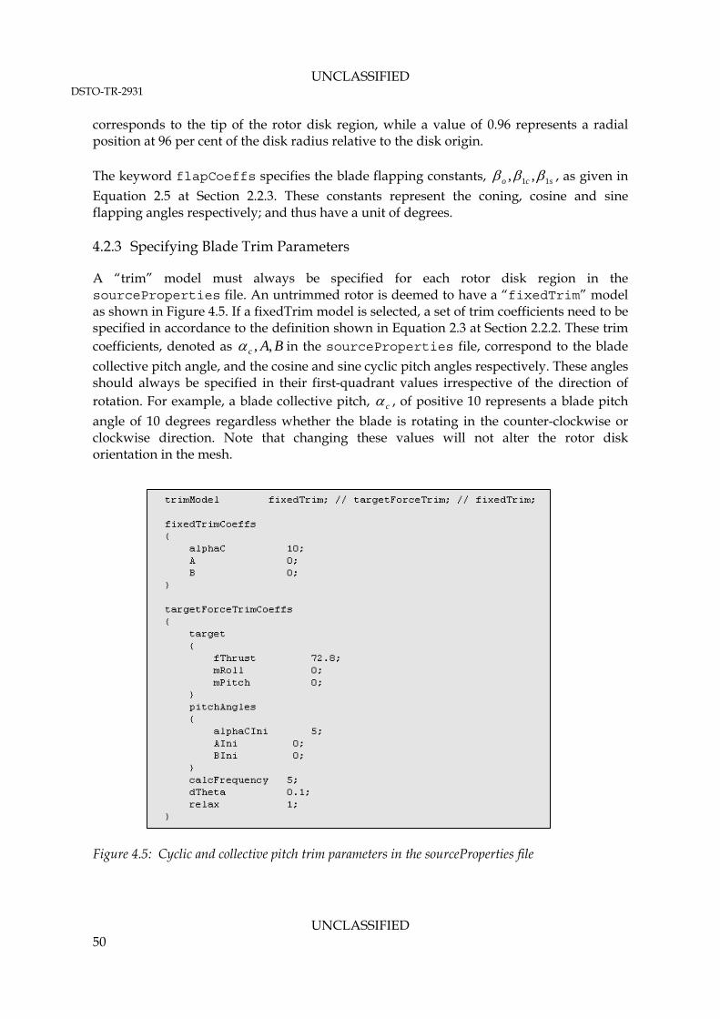
UNCLASSIFIED DSTO-TR-2931
UNCLASSIFIED 50
corresponds to the tip of the rotor disk region, while a value of 0.96 represents a radial position at 96 per cent of the disk radius relative to the disk origin. The keyword flapCoeffs specifies the blade flapping constants, sco 11 ,, , as given in
Equation 2.5 at Section 2.2.3. These constants represent the coning, cosine and sine flapping angles respectively; and thus have a unit of degrees. 4.2.3 Specifying Blade Trim Parameters
A “trim” model must always be specified for each rotor disk region in the sourceProperties file. An untrimmed rotor is deemed to have a “fixedTrim” model as shown in Figure 4.5. If a fixedTrim model is selected, a set of trim coefficients need to be specified in accordance to the definition shown in Equation 2.3 at Section 2.2.2. These trim coefficients, denoted as BAc ,, in the sourceProperties file, correspond to the blade
collective pitch angle, and the cosine and sine cyclic pitch angles respectively. These angles should always be specified in their first-quadrant values irrespective of the direction of rotation. For example, a blade collective pitch, c , of positive 10 represents a blade pitch
angle of 10 degrees regardless whether the blade is rotating in the counter-clockwise or clockwise direction. Note that changing these values will not alter the rotor disk orientation in the mesh.
Figure 4.5: Cyclic and collective pitch trim parameters in the sourceProperties file

UNCLASSIFIED DSTO-TR-2931
UNCLASSIFIED 51
The blade trimming calculation can be “activated” by specifying “targetForceTrim” as the trimModel. When blade trimming is carried out in the simulation, the fixedTrimCoeffs entries will be ignored by the code. Instead, the user must specify the targetForceTrimCoeffs entries as shown in Figure 4.5. As previously discussed in Section 2.3.7 and Section 3.4.3, the trimming is done by perturbing the blade collective and cyclic pitch angles at a frozen flow state (at each flow solver iteration) to find a combination of blade collective and cyclic pitch angles that will return the global thrust and moments on the rotor disk that match the user-specified target rotor thrust and moments. The keyword fThrust shown in Figure 4.5 specifies the desired total thrust acting on the disk in Newtons. The keywords mRoll and mPitch specify the desired total rolling and pitching moments acting on the disk in Newton-meters. Usually the rotor total thrust and moments for a particular flight condition are specified by the Original Equipment Manufacturer (OEM) as non-dimensionalised quantities of coefficients of thrust and coefficients of moments as given by Equations 2.37 through 2.39 in Section 2.3.7. The keyword alphaCIni, AIni and BIni are the initial guesses of the blade collective pitch angle and cyclic pitch coefficients (refer to Equation 2.36 in Section 2.3.7). The keyword calcFrequency specifies the interval (in flow iterations) in-between trimming routines. The keyword dTheta specifies the angles by which the local blade AOA needs to be perturbed during trimming (the default value is 0.05 degree). The URF for the newly calculated AOA during trimming is specified by the keyword relax as shown in Figure 4.5. Note that for stability reasons, this factor should be kept at one unless the trimming routine is unable to find a trimmed solution within its iteration limits. This iteration limit in the trimming loop is “hard-coded” to be 50 iterations, in the source file “targetForceTrim.C”. However, the user may override this setting by adding a keyword nIter and specifying an integer value in the line following the relax keyword. 4.2.4 Specifying Blade Geometry and Section Profile
A blade geometry and blade section profile must be specified for each of the rotor objects created in the “sourceProperties” file. An example of a setup for a linearly tapering blade with a NACA0015 section is shown in Figure 4.6. In this example, the blade has zero twist along its radius, and is linearly tapered from a chord length of 0.086 m at r = 0.45 m, to a chord length of 0.075 m at its tip. The blade radius is shown to be 0.8 m. Note that currently only a linear taper is supported by the code.

UNCLASSIFIED DSTO-TR-2931
UNCLASSIFIED 52
Figure 4.6: Blade geometry and profile specification in the sourceProperties file
The “NACA0015” shown in Figure 4.6 can be arbitrarily named. However, this naming must correspond to the “profile” entry setup as described later in Section 4.2.5. The setup shown also allows the blade to be defined in multiple segments, where in each segment an independent section profile, and a linear variation of twist angle and taper, can be defined. Each blade segment can be defined using a pair of entries specifying the segment start and end radii, blade twist angle, and chord. 4.2.5 Specifying Section Profile Lift and Drag Curves
Following the blade geometry and section profile specification, the lift and drag curves for a range of AOA must be specified for each blade segment. Using the example shown in Figure 4.6, NACA0015 lift and drag curves as a function of AOA must be specified. This is shown in Figure 4.7. As shown in Figure 4.7, there are two ways of specifying the lift and drag curves for the selected NACA0015 airfoil, i.e. using a “series” mode or a “lookup” mode. In the “series” mode, the Cl curve is represented using a sine series, while the Cd curve is represented using a cosine series as shown by the equations in the same Figure. The numbers shown in the sourceProperties file (Figure 4.7) are the ith coefficient ilC
and idC for the respective series equations. These coefficients have been generated by
fitting the Cl and Cd versus AOA using the sine or cosine series respectively. The fitted raw data for the Cl and Cd must cover AOA ranging from – to +. In the “lookup” mode, the lift and drag curves are described using point data as shown in Figure 4.7. During computation, the values for Cl and Cd for any AOA are linearly interpolated from the point data specified in the sourceProperties file. The data must cover AOA ranging from – to +.
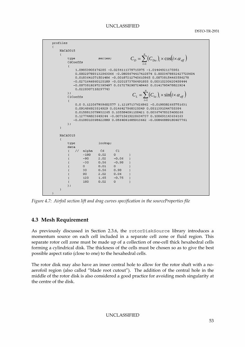
UNCLASSIFIED DSTO-TR-2931
UNCLASSIFIED 53
Figure 4.7: Airfoil section lift and drag curves specification in the sourceProperties file
4.3 Mesh Requirement
As previously discussed in Section 2.3.6, the rotorDiskSource library introduces a momentum source on each cell included in a separate cell zone or fluid region. This separate rotor cell zone must be made up of a collection of one-cell thick hexahedral cells forming a cylindrical disk. The thickness of the cells must be chosen so as to give the best possible aspect ratio (close to one) to the hexahedral cells. The rotor disk may also have an inner central hole to allow for the rotor shaft with a no-aerofoil region (also called “blade root cutout”). The addition of the central hole in the middle of the rotor disk is also considered a good practice for avoiding mesh singularity at the centre of the disk.
n
ieffiDD iCC
1
cos
n
ieffilL iCC
1
sin

UNCLASSIFIED DSTO-TR-2931
UNCLASSIFIED 54
An example of this setup is shown in Figure 4.8. Note that due to the specific implementation of the momentum source terms (discussed in Section 2.3.6), only hexahedral cells are allowed in the rotor disk region.
Figure 4.8: An example of rotor disk mesh using structured hexahedral cells
Although the rotor disk region can only be constructed from hexahedral cells, other parts of the domain may be constructed using any other type of cells, i.e. tetrahedral or polyhedral. However, if tetrahedral cells are used in the domain, a series of pyramid shaped cells need to be attached on the rotor disk surfaces in order to smoothly blend the hexahedral cells in the rotor disk region to the tetrahedral cells in the domain. An example of this is shown in Figure 4.9.
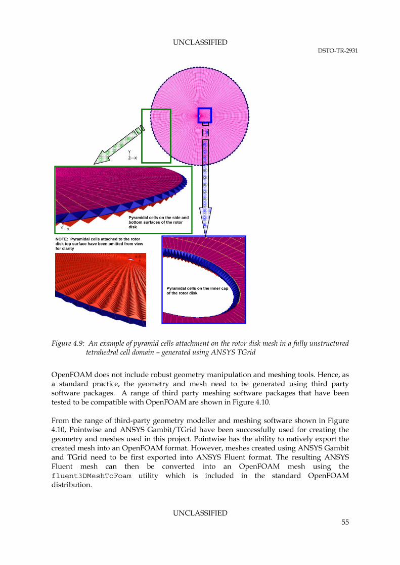
UNCLASSIFIED DSTO-TR-2931
UNCLASSIFIED 55
Figure 4.9: An example of pyramid cells attachment on the rotor disk mesh in a fully unstructured
tetrahedral cell domain – generated using ANSYS TGrid
OpenFOAM does not include robust geometry manipulation and meshing tools. Hence, as a standard practice, the geometry and mesh need to be generated using third party software packages. A range of third party meshing software packages that have been tested to be compatible with OpenFOAM are shown in Figure 4.10. From the range of third-party geometry modeller and meshing software shown in Figure 4.10, Pointwise and ANSYS Gambit/TGrid have been successfully used for creating the geometry and meshes used in this project. Pointwise has the ability to natively export the created mesh into an OpenFOAM format. However, meshes created using ANSYS Gambit and TGrid need to be first exported into ANSYS Fluent format. The resulting ANSYS Fluent mesh can then be converted into an OpenFOAM mesh using the fluent3DMeshToFoam utility which is included in the standard OpenFOAM distribution.
Pyramidal cells on the side and bottom surfaces of the rotor disk
Pyramidal cells on the inner cap of the rotor disk
NOTE: Pyramidal cells attached to the rotor disk top surface have been omitted from view for clarity

UNCLASSIFIED DSTO-TR-2931
UNCLASSIFIED 56
Figure 4.10: OpenFOAM user environment
The ANSYS Gambit and ANSYS TGrid software are widely available within DSTO. Therefore, only the method of generating the rotor disk mesh using ANSYS Gambit and TGrid will be discussed in this report. 4.3.1 Generating Rotor Disk Mesh Using ANSYS Gambit and ANSYS TGrid for Use in OpenFOAM
Reference 1 provides a detailed discussion on the development of the VBM in the ANSYS Fluent environment. A detailed procedure on how to create the rotor disk mesh in a CFD model using ANSYS Gambit and TGrid is also included in Section 3.2 of Reference 1. Therefore, this procedure will not be repeated in this report. However, during review of Reference 1, it was found that the use of prismatic cells to construct the rotor disk is not appropriate for the VBM method (refer to Section 2.3.6). Therefore, it is recommended that the rotor disk region is constructed in ANSYS Gambit (or any other preferred geometry modelling software) using structured hexahedral cells only. Pyramidal cell caps can then be placed on the rotor disk surfaces to transition the hexahedral cells to the tetrahedral cells for meshing the fluid domain as per the guidance given in Reference 1. Following the procedure given at Reference 1, the mesh can be saved as a Fluent type mesh file format (.msh)6. Although the OpenFOAM translation routine, “fluent3DMeshToFoam” is able to translate the .msh file into OpenFOAM format, it was found that the same routine performs better with ANSYS Fluent case file format (.cas). Therefore, it is considered to be a good practice to load the ANSYS Gambit/TGrid generated mesh into ANSYS Fluent, and then save the mesh into a “dummy” case file (in .cas format).
6 IMPORTANT: the Fluent case file will need to be written in ASCII format for translation into OpenFOAM format.

UNCLASSIFIED DSTO-TR-2931
UNCLASSIFIED 57
Conversion of an ANSYS Fluent case into an OpenFOAM format requires the user to first set up a standard OpenFOAM case directory structure (previously shown in Figure 3.7) in the intended OpenFOAM working path. For the purpose of importing the mesh from a Fluent format into OpenFOAM, the “polyMesh” directory inside the case directory structure must be empty. The conversion routine will subsequently populate this directory to contain the files needed to define the mesh in OpenFOAM. Prior to the mesh conversion, the “dummy” ANSYS Fluent case file needs to be copied into the OpenFOAM case “root directory”. This is the top level location in the case directory structure. Following this, the mesh conversion can be started by issuing the following command from the Bash shell terminal from the case root directory location: $ fluent3DMeshToFoam –scale <factor> <filename.cas> -writeZones -writeSets The input <factor> is the mesh geometric scaling factor to be applied during conversion, e.g. if the mesh was created in the unit of mm, the entry <factor> should be replaced with 0.001. The input <filename.cas> should be replaced with the ANSYS Fluent case filename, including the full or relative path to the ANSYS Fluent case file. Following a successful mesh conversion, the polyMesh directory will be populated with the files as shown in Figure 4.11. Details on the mesh topology and conventions used in OpenFOAM are available from Chapter 5 of Reference 13.
Figure 4.11: polyMesh directory structure in an OpenFOAM case
The “points”, “cells”, and “faces” files contain a long list of numbers which are used for cell and face addressing. The “boundary” file contains the patch definition in the mesh. It is important to note that the patch definitions contained in the “boundary” file are not the boundary conditions for the case. The boundary conditions need to be set up in the “0” directory in the case directory. Boundary conditions setup will be discussed in Section 4.4. Prior to setting up the boundary conditions for the case, the user should check if the separate cellZone or region that the rotor disk was created in has been preserved

UNCLASSIFIED DSTO-TR-2931
UNCLASSIFIED 58
correctly during the mesh conversion. The simplest way to check this is to make sure that the “cellZone” file located in the polyMesh directory has at least two separate cellZone as indicated in Figure 4.12. The final step involved in the process of preparing an OpenFOAM mesh from an ANSYS Fluent mesh is to reorder the mesh addressing in the domain to improve the computational performance of the solvers. The reordering procedure involves rearranging the points, faces and cells addressing to improve the bandwidth of the FV Matrix, once constructed, during runtime. In general, the faces and cells are reordered so that the neighboring cells are near each other in the zone and in memory. Since most of the computational loops are over faces (e.g. calculation of the cell face flux), it is best to place two adjacent cells next to each other in the memory addressing slots. The imported mesh can be reordered by issuing the following command from the case root directory: $ renumberMesh -overwrite
Figure 4.12: polyMesh directory structure in an OpenFOAM case
4.4 Setting Up the Boundary Conditions
The OpenFOAM mesh conversion utility, fluent3DMeshToFoam, will attempt to capture the ANSYS Fluent boundary condition definitions as much as possible. However, since there is no clear, direct correspondence between the OpenFOAM and ANSYS Fluent boundary conditions, the user must make manual adjustments in the OpenFOAM case
Total number of cellZones (or regions) in the mesh
rotor disk region name
Total cell count in rotor disk region

UNCLASSIFIED DSTO-TR-2931
UNCLASSIFIED 59
prior to running the case. The following sub-sections will provide a high-level overview of boundary conditions that are readily available in OpenFOAM for typical cases involving the use of VBM. 4.4.1 Overview of Boundary Patches and Boundary Conditions in OpenFOAM
Following a successful mesh conversion from an ANSYS Fluent mesh format to an OpenFOAM format, a “boundary” file will be automatically created by fluent3DMeshToFoam and placed inside the polyMesh directory. The “boundary” file contains the type associated with each imported domain boundary surface included in the Fluent mesh that are readily recognisable by the fluent3DMeshToFoam. These boundary types include: patch, wall, symmetry plane, and cyclic plane. If a 2D mesh is imported, then a pair of empty plane or wedge plane will be created to simulate the symmetry plane or the cyclic plane for the 2D planar and 2D axisymmetric case respectively. Note that a 2D mesh is not suitable for using the rotorDiskSource library. In OpenFOAM, a boundary surface is generally broken up into a set of patches. One patch may include one or more enclosed areas of the boundary surface which do not necessarily need to be physically connected (Reference 13). The type definition included in the boundary file is therefore only associated with the mesh hierarchy. In addition to the type definition included in the boundary file, a numerical boundary condition must also be defined for each boundary surface. In summary, there are two attributes associated with a “patch” that are described below in their natural hierarchy. Figure 4.13 also shows the names of different patch types introduced at each level of the hierarchy.
Base type. The type of patch described purely in terms of geometry or a data ‘communication link’.
Numerical type. The boundary conditions describing the treatment of field variables on a particular base type patch. These are split into two categories:
a. Primitive type. The base numerical patch condition assigned to a field variable on the patch. Some examples of these are: the Dirichlet Condition (fixdValue), zero Neumann Condition (zeroGradient), etc.
b. Derived type. A complex patch condition, derived from the primitive type, assigned to a field variable on the patch. Some examples of these are: the totalPressure, inletOutlet, flowRateInletVelocity, etc.

UNCLASSIFIED DSTO-TR-2931
UNCLASSIFIED 60
Figure 4.13: Boundary patch hierarchy in an OpenFOAM case (reproduced from Reference 13)
4.4.2 Setting Up Boundary Conditions for an OpenFOAM Case
As discussed in the previous Section, the OpenFOAM mesh conversion utility, fluent3DMeshToFoam, is capable of recognising the “base type” of each boundary patch. This means that boundary surfaces with the following attributes: wall; symmetry plane; and periodic (cyclic); are automatically setup in the boundary file. However, all other derived types, such as: velocity inlet, pressure inlet, pressure outlet, etc, from ANSYS Fluent are assigned a basic type of patch in the boundary file. Whilst each of these boundary condition types carries a specific numerical definition in ANSYS Fluent, they are not made available to the public. Therefore, a set of numerical boundary conditions that is considered to be equivalent to that in ANSYS Fluent was investigated. In addition to setting up the “base type” for each of the boundary surfaces in the boundary file, a “numerical type” must also be assigned for each of the field variables at each of the boundary surfaces included in the mesh. Setting up the numerical boundary conditions in OpenFOAM involves creating a series of text files in a “0” directory as previously shown in Figure 3.7. An example of an OpenFOAM case that was used for validating the rotorDiskSource code has also been enclosed in this report (in Appendix B), and may serve as a template for setting up future cases. Further details on the more specific format of these boundary condition files are provided at Chapter 5.2 of the OpenFOAM User Guide at Reference 13. Table 4.3 provides a map translating the commonly used ANSYS Fluent boundary conditions to those that are readily available in OpenFOAM. The OpenFOAM boundary conditions shown in the map are not exhaustive, and are typically the simplest available types. There is very limited information on some of these boundary conditions available in the OpenFOAM User Guide (Reference 13, Chapter 5.2). Thus, in the author’s opinion, the simplest way to learn more about the types of boundary conditions that are available in OpenFOAM and their numerical implementation is through the source code. The source

UNCLASSIFIED DSTO-TR-2931
UNCLASSIFIED 61
code for all available boundary conditions in OpenFOAM can be found at the following path: ${FOAM_SRC}/finiteVolume/fields/fvPatchFields/derived The method and entries required to set up a boundary condition in OpenFOAM are not necessarily uniform across all types. However, description of such methods required to setup each boundary condition available in OpenFOAM is considered to be beyond the scope of the current report. Nonetheless, the sample cases provided in Appendix B of this report provide some examples on how the boundary conditions are typically set up in a case involving a helicopter in forward flight. The boundary conditions setup can be found in the files located inside the “0” directory of the case as given in Appendices B.2.6 through B.2.12. These files need to be created manually in every case set up. The methods required for specifying any other boundary conditions apart from those included in Appendix B can always be obtained from the source code. 4.4.3 Rotor Disk Boundary Conditions in OpenFOAM
The construction of the rotor disk geometry as shown in Figure 4.8 and Figure 4.9 requires construction of several internal surfaces bounding the disk. Following the meshing of the rotor disk, it is customary to define these disk internal surfaces as “interior” type boundaries in ANSYS Gambit and ANSYS TGrid. Unfortunately, there is currently no boundary condition in OpenFOAM that is equivalent to the “interior” type that is available in ANSYS Fluent (and most of other commercial CFD packages, such as ANSYS CFX). Any “interior” type boundaries in the ANSYS Fluent mesh will be ignored during the conversion; hence such boundary will not appear in the “polyMesh/boundary” file in the OpenFOAM mesh. However, the geometry definition of the surface of such boundaries is retained in the OpenFOAM mesh in the form of a “faceZone”. This faceZone may still prove useful for post-processing the result using paraview. Therefore, it is still considered to be beneficial to place the “interior” type surface or boundary when creating the ANSYS Fluent mesh for post-processing purposes. Section 4.6 will provide limited guidance on how an “interior” surface may be used for post-processing in OpenFOAM using paraview.

UNCLASSIFIED DSTO-TR-2931
UNCLASSIFIED 62
Table 4.3: Mapping of ANSYS Fluent boundary conditions to standard OpenFOAM numerical type boundary conditions
OpenFOAM 2.1.x "Numerical Type" in Time Directory (If simulation is started from 0, the Time Directory is 0)
ANSYS Fluent BC Type
OpenFOAM 2.1.x "Base Type" in constant/ polyMesh/ boundary
0/p 0/U 0/k 0/epsilon
mass flow rate inlet
patch zeroGradient; waveTransmissive
1
flowRateInletVelocity fixedValue; mappedFixedValue
2;
turbulentIntensityKineticEnergyInlet
fixedValue; mappedFixedValue
2;
compressible::turbulentMixingLengthDissipationRateInlet
3
velocity inlet patch zeroGradient; waveTransmissive
1
fixedValue; uniformFixedValue; mappedFixedValue
2
fixedValue; mappedFixedValue
2;
turbulentIntensityKineticEnergyInlet
fixedValue; mappedFixedValue
2;
turbulentMixingLengthDissipationRateInlet
3
pressure inlet patch fixedValue; totalPressure
4
zeroGradient; pressureInletVelocity
5
outletInlet outletInlet
pressure outlet patch zeroGradient; totalPressure
4;
inletOutlet; pressureInletOutletVelocity
6
inletOutlet inletOutlet
wall - no slip wall zeroGradient fixedValue7 fixedValue
8;
compressible::kqRWallFunction
10
zeroGradient9;
compressible::epsilonWallFunction
10
wall - slip wall slip slip slip slip
interior N/A N/A N/A N/A N/A
symmetry symmetry symmetryPlane symmetryPlane symmetryPlane symmetryPlane
periodic cyclic cyclic cyclic cyclic cyclic
N/A empty13
empty empty empty empty
N/A wedge14
wedge wedge wedge wedge
Table continues over page…

UNCLASSIFIED DSTO-TR-2931
UNCLASSIFIED 63
…Table continued
OpenFOAM 2.1.x "Numerical Type" in Time Directory (If simulation is started from 0, the Time Directory is 0)
ANSYS Fluent BC Type
OpenFOAM 2.1.x "Base Type" in constant/ polyMesh/ boundary
0/omega 0/T 0/mut 0/alphat
mass flow rate inlet
patch fixedValue; mappedFixedValue
2;
compressible::turbulentMixingLengthDissipationRateInlet
3
fixedValue; mappedFixedValue
2;
totalTemperature
4
calculated calculated
velocity inlet patch fixedValue; mappedFixedValue
2;
fixedValue; mappedFixedValue
2;
calculated calculated
pressure inlet patch outletInlet zeroGradient; outletInlet; inletOutletTotalTemperature
11
calculated calculated
pressure outlet
patch inletOutlet zeroGradient; inletOutlet; inletOutletTotalTemperature
11;
calculated calculated
wall - no slip wall zeroGradient9;
compressible::epsilonOmegaFunction
10
zeroGradient; compressible::temperatureThermoBaffle1D
12
mutKWallFunction15
; mutUWallFunction
16
alphatWallFunction; alphatJayatillekeWallFunction
wall - slip wall slip slip slip slip
Note:
1. waveTransmissive is a boundary conditions that may be used if strong pressure reflection on the boundary is detected during the simulation, that causes numerical instability to develop. Otherwise, the use of zeroGradient is recommended.
2. mappedFixedValue is used when the distribution of the “value” across the boundary is not uniform and is known. For example: parabolic velocity inlet.

UNCLASSIFIED DSTO-TR-2931
UNCLASSIFIED 64
3. The compressible::turbulentMixingLengthDissipationRateInlet can only be used for compressible flow solvers (e.g. rhoSimpleFoam). If an incompressible flow solver is used (e.g. simpleFOAM), use the equivalent turbulentMixingLengthDissipationRateInlet.
4. totalPressure and totalTemperature should be used when running a compressible flow solver.
5. Use pressureInletVelocity for U when totalPressure is used for p.
6. Use pressureInletOutletVelocity for U when totalPressure is used for p.
7. Set value to “uniform 0”.
8. Set turbulent kinetic energy at the wall (k) to zero only when the mesh resolution at the wall is adequate to resolve the flow to the wall (low Reynolds number mesh). Otherwise, use wall function.
9. Use zeroGradient for epsilon and/or omega at the wall only when the mesh resolution at the wall is adequate to resolve the flow to the wall (low Reynolds number mesh). Otherwise, use wall function.
10. These BCs are for compressible flow solvers. When running an incompressible flow solver, remove the “compressible::” from the BC type name.
11. Use inletOutletTotalTemperature on a pressure boundary when totalTemperature is specified at an inlet boundary.
12. BC for calculating 1D normal conduction through a thin wall. zeroGradient condition for temperature at a wall will result in an adiabatic wall.
13. BC for the “front” and “back” planes of a planar 2D mesh – only used in a 2D simulation.
14. BC for the wedge planes of an axisymmetric 2D mesh – only used in a 2D axisymmetric simulation.
15. Wall function for turbulent vicosity based on near wall values of turbulent kinetic energy (k).
16. Wall function for turbulent vicosity based on near wall values of velocity.

UNCLASSIFIED DSTO-TR-2931
UNCLASSIFIED 65
4.5 Solution Driving Strategy
4.5.1 Overview
The steady-state RANS solvers included in the standard OpenFOAM distribution are pressure-based segregated solvers that are based on the SIMPLE algorithm. The numerical stability of such RANS algorithm is often determined by a range of interacting factors. These factors are generally associated with:
1. appropriateness of the boundary conditions chosen; 2. appropriateness of the chosen initial condition; 3. the orthogonality of the cell faces in the mesh; 4. the number of PDEs being solved simultaneously during the simulation; 5. the method of solving the coupled PDEs, either by using a segregated method
(explicit coupling with quasi-linearisation) or direct implicit coupling method; 6. selection of the numerical discretisation scheme for each term in the PDEs being
solved; 7. selection of linear solvers employed in the algorithm, and 8. selection of the under-relaxation factors.
The original SIMPLE method was first introduced by Patankar and Spalding at Reference 16. The method was further extended for compressible flow and heat transfer application at Reference 17. However, its suitability is often only limited to weakly compressible flow (Ma < 0.7). In general, the SIMPLE algorithm seeks to convert the continuity equation into an equation for pressure (often referred to as “pressure corrector”), and to use the corrected pressure to correct the initial solution of the momentum equation. The solution is then iterated until a “converged solution” is reached, meaning the pressure corrector becomes zero anywhere in the solution. This particular method, while proven to be low-cost and effective in solving the steady-state version of the Navier-Stokes equations, is inherently unstable because the solution may change abruptly from one iteration to the next, leading to a divergence in the calculation. Therefore, an appropriate combination of solver settings and solution control methods needs to be applied to the case to stabilise the run. Unfortunately due to the diverse flow regimes (even when the simulated flow is only limited to the incompressible and compressible flow regimes), there is no single method that will ensure a stable simulation for all possible flow conditions and flow regimes while at the same time maintaining a reasonable accuracy of the solution. For example, using a Gauss upwind discretisation scheme (1st order accurate scheme) for all convective terms in the momentum equation may lead to a more numerically stable run than using a Gauss linear scheme (2nd order accurate scheme). However, this may lead to a less accurate solution as the upwind scheme introduces a higher degree of numerical diffusion (artificial diffusion) in the solution. An alternative method would be to start the run with a Gauss upwind scheme for the convective terms until the pressure field is fully developed in the domain, then switching to the Gauss linear scheme in the more advanced stage of the iteration to get a better converged solution. The numerical stability may also be enhanced by heavily under-relaxing the pressure field, which may dampen any numerical fluctuations that occur in the pressure solution.

UNCLASSIFIED DSTO-TR-2931
UNCLASSIFIED 66
In an OpenFOAM case, the numerical discretisation schemes are specified in the fvSchemes file located inside the system directory of the case. The linear solver settings and solution control methods are set using the fvSolution file located inside the system directory of the case. Users will need to create these files manually following the specifications given in Section 4.4 and Section 4.5 of the OpenFOAM User Guide (Reference 13). While the User Guide (Reference 13) provides some explanations of the numerical schemes and linear solver settings that are available in OpenFOAM, they are by no means exhaustive. Therefore, it may also be useful to refer to the sample case files provided in Appendix B of this report. The following sub-sections will discuss some of the more important considerations that may help in stabilising the steady RANS simulation in OpenFOAM using the simpleFoam or rhoSimpleFoam solvers. These strategies are generally applicable, but not limited, to cases typically considered by IRSA, e.g. transport of hot exhaust plumes around a helicopter in-flight. 4.5.2 Appropriateness of Boundary Conditions
Inappropriate boundary conditions are the most common cause for numerical instability in performing a steady RANS simulation. This difficulty with setting-up proper boundary conditions for a problem set has largely been alleviated in a lot of market-leading commercial CFD packages (such as ANSYS Fluent or ANSYS CFX) for many commonly considered flow cases. Many of the commercial CFD packages now employ an extensive use of GUI to simplify the case set up procedure, and at the same time automate the process of setting up the numerical boundary condition type for each of the field variables. The main reasoning behind this automation is to minimise the chance of human error by minimising the amount of user’s input. However, this has an adverse effect of obscuring the actual implementation of the boundary conditions from the user. In OpenFOAM, the user has the ability to set every boundary condition that is required to solve each equation (refer to Section 4.4). However, this may also lead to inappropriate specification of boundary conditions which causes the system of equations to be “numerically stiff”, and eventually leading to a divergence solution during the iteration. To minimise the chance of setting-up a numerically stiff case, the user needs to consider the following factors:
1. Avoid using a Dirichlet type condition (e.g. fixedValue) for both the pressure and velocity on a boundary. For example, if a fixedValue velocity is set at an inlet boundary, a zeroGradient pressure must be selected on that boundary.
2. A case must not have fixedValue pressure being setup on all boundaries in a computational domain, nor a zeroGradient pressure being setup on all boundaries.
3. If the flow is compressible, a totalPressure boundary condition must be used for pressure on all inlet and outlet boundaries (refer to Table 4.3).

UNCLASSIFIED DSTO-TR-2931
UNCLASSIFIED 67
4. Use the inletOutlet or pressureInletOutletVelocity type boundary conditions for velocity on a pressure boundary for incompressible flow and compressible flow cases respectively. This is particularly important on boundaries where “back-flow” is expected. This is because the inletOutlet type is a “mixed condition” that sets a zeroGradient condition on the boundary face if the face flux vector on that face is pointing out of the domain, and sets a fixedValue condition if the face flux vector on that face is pointing into the domain (i.e. backflow). inletOutlet is also a better boundary condition for turbulence quantities across a pressure boundary.
5. Ramp-up the velocity (or mass flow rate) at the inlet boundary by using the “timeVarying” set up of the fixedValue or flowRateInletVelocity boundary conditions. An example of how to use the time-varying option with the flowRateInletVelocity is shown at Figure 4.14. Note that a volumetric flow rate (instead of a mass flow rate) must be defined for flowRateInletVelocity when used with an incompressible flow solver (e.g. simpleFoam).
4.5.3 Appropriateness of Initial Condition
An initial condition must be set for each of the field variables being solved. The initial conditions are set up using the keyword internalField (refer to the sample case setup at Appendix B). The simplest type of initial condition in OpenFOAM is as follows: internalField “uniform (0 0 0)” for a vector field; internalField “uniform 0” for a scalar field. Starting the simulation from a zero solution is known to potentially cause numerical instability in the flow-field at later stages during the iteration. Regions in the flow-field with strong gradients (such as the engine exhaust exit plane in a helicopter simulation) are particularly prone to numerical instability. Therefore, where a complex simulation is concerned (such as flow around a helicopter in forward flight with hot exhaust plume), it is recommended that the solution is developed gradually. In such a scenario, the simulation may be started from a quiescent condition by first running a potential flow solver (potentialFoam) or incompressible flow solver (simpleFoam) without modelling the compressible flow feature. This will initially establish the pressure field and rough wake field around the helicopter. The incompressible solution can subsequently be mapped or interpolated into a new compressible flow case with the exhaust plume activated. Ramping up the exhaust plume flow rate will also aid in stabilising the run. The standard distribution of OpenFOAM comes with a utility to map or interpolate field solution between meshes or cases. The following command can be used to map fields: $ mapFields –consistent –sourceTime <time> -targetTime <time> <sourceCasePath>
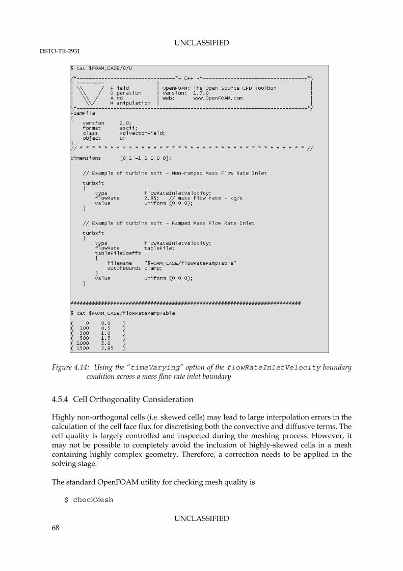
UNCLASSIFIED DSTO-TR-2931
UNCLASSIFIED 68
Figure 4.14: Using the “timeVarying” option of the flowRateInletVelocity boundary
condition across a mass flow rate inlet boundary
4.5.4 Cell Orthogonality Consideration
Highly non-orthogonal cells (i.e. skewed cells) may lead to large interpolation errors in the calculation of the cell face flux for discretising both the convective and diffusive terms. The cell quality is largely controlled and inspected during the meshing process. However, it may not be possible to completely avoid the inclusion of highly-skewed cells in a mesh containing highly complex geometry. Therefore, a correction needs to be applied in the solving stage. The standard OpenFOAM utility for checking mesh quality is $ checkMesh

UNCLASSIFIED DSTO-TR-2931
UNCLASSIFIED 69
The user must observe the reported average value and maximum value of the mesh non-orthogonality from running the checkMesh utility. An average value of less than 30 is considered good. At least 1 or 2 nonOrthogonalCorrectors are needed when checkMesh reports an average value of higher than 50. The number of nonOrthogonalCorrectors can be set in the “system/fvSolution” file of the case, under the keyword nNonOrthogonalCorrectors. If checkMesh reports a maximum cell non-orthogonality of higher than 50, it is recommended that a leastSquares method is used for calculating the gradient terms, instead of the Gauss linear scheme. The discretisation scheme for the gradient term is set in the case “system/fvSchemes” file, under the keyword gradSchemes. 4.5.5 Selection of Numerical Discretisation Scheme
OpenFOAM requires the user to set up the discretisation schemes that are to be used for each PDE being solved. These include all gradient terms, convective terms (divergence term), diffusion terms (laplacian term), and surface normal gradient terms. The numerical schemes are specified in the “system/fvSchemes” file for each case. Section 4.4 of the OpenFOAM User Guide (Reference 13) contains some limited explanations on the numerical discretisation setup in a case. An example of the fvSchemes file has also been included in the attached sample case files at Appendix B.2.14. There are several differences in the way the discretisation schemes are setup (or selected) in OpenFOAM and ANSYS Fluent cases. A map translating the commonly used ANSYS Fluent numerical schemes (or discretisation schemes) to those that are readily available in OpenFOAM is shown in Table 4.4. Due to the limited information available from the ANSYS Fluent manual, some educated judgement was applied to deduce the possible implementation of the same discretisation scheme in Fluent. It is considered a standard practice to start a complex flow simulation (using steady pressure-based RANS formulation) with first order accurate schemes for the divergence terms (i.e. Gauss upwind). The residuals are then monitored during runtime. The solution may be restarted using higher order-schemes (such as Gauss linear) when the residuals have shown a significant drop (approximately by two orders of magnitude), and any instabilities in the pressure residuals have gradually disappeared. A more conservative approach would be to restart the solution using higher order schemes from a fully converged first order accurate solution.
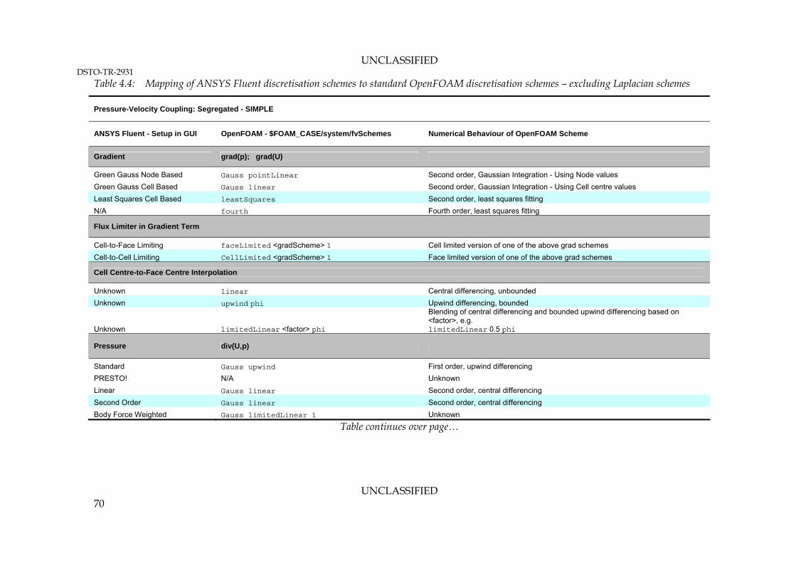
UNCLASSIFIED DSTO-TR-2931
UNCLASSIFIED 70
Table 4.4: Mapping of ANSYS Fluent discretisation schemes to standard OpenFOAM discretisation schemes – excluding Laplacian schemes
Pressure-Velocity Coupling: Segregated - SIMPLE
ANSYS Fluent - Setup in GUI OpenFOAM - $FOAM_CASE/system/fvSchemes Numerical Behaviour of OpenFOAM Scheme
Gradient grad(p); grad(U)
Green Gauss Node Based Gauss pointLinear Second order, Gaussian Integration - Using Node values
Green Gauss Cell Based Gauss linear Second order, Gaussian Integration - Using Cell centre values
Least Squares Cell Based leastSquares Second order, least squares fitting
N/A fourth Fourth order, least squares fitting
Flux Limiter in Gradient Term
Cell-to-Face Limiting faceLimited <gradScheme> 1 Cell limited version of one of the above grad schemes
Cell-to-Cell Limiting CellLimited <gradScheme> 1 Face limited version of one of the above grad schemes
Cell Centre-to-Face Centre Interpolation
Unknown linear Central differencing, unbounded
Unknown upwind phi Upwind differencing, bounded
Unknown limitedLinear <factor> phi
Blending of central differencing and bounded upwind differencing based on <factor>, e.g. limitedLinear 0.5 phi
Pressure div(U,p)
Standard Gauss upwind First order, upwind differencing
PRESTO! N/A Unknown
Linear Gauss linear Second order, central differencing
Second Order Gauss linear Second order, central differencing
Body Force Weighted Gauss limitedLinear 1 Unknown
Table continues over page…
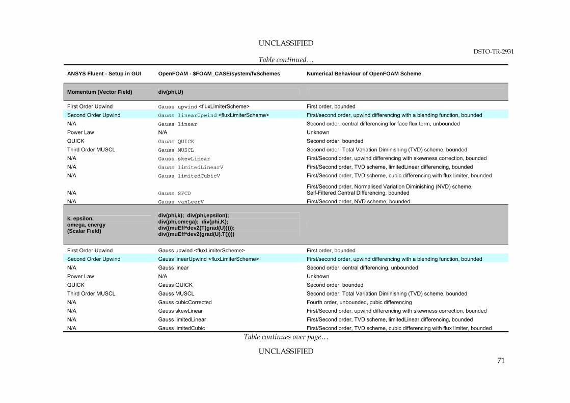
UNCLASSIFIED DSTO-TR-2931
UNCLASSIFIED 71
Table continued…
ANSYS Fluent - Setup in GUI OpenFOAM - $FOAM_CASE/system/fvSchemes Numerical Behaviour of OpenFOAM Scheme
Momentum (Vector Field) div(phi,U)
First Order Upwind Gauss upwind <fluxLimiterScheme> First order, bounded
Second Order Upwind Gauss linearUpwind <fluxLimiterScheme> First/second order, upwind differencing with a blending function, bounded
N/A Gauss linear Second order, central differencing for face flux term, unbounded
Power Law N/A Unknown
QUICK Gauss QUICK Second order, bounded
Third Order MUSCL Gauss MUSCL Second order, Total Variation Diminishing (TVD) scheme, bounded
N/A Gauss skewLinear First/Second order, upwind differencing with skewness correction, bounded
N/A Gauss limitedLinearV First/Second order, TVD scheme, limitedLinear differencing, bounded
N/A Gauss limitedCubicV First/Second order, TVD scheme, cubic differencing with flux limiter, bounded
N/A Gauss SFCD First/Second order, Normalised Variation Diminishing (NVD) scheme, Self-Filtered Central Differencing, bounded
N/A Gauss vanLeerV First/Second order, NVD scheme, bounded
k, epsilon, omega, energy (Scalar Field)
div(phi,k); div(phi,epsilon); div(phi,omega); div(phi,K); div((muEff*dev2(T(grad(U))))); div((muEff*dev2(grad(U).T())))
First Order Upwind Gauss upwind <fluxLimiterScheme> First order, bounded
Second Order Upwind Gauss linearUpwind <fluxLimiterScheme> First/second order, upwind differencing with a blending function, bounded
N/A Gauss linear Second order, central differencing, unbounded
Power Law N/A Unknown
QUICK Gauss QUICK Second order, bounded
Third Order MUSCL Gauss MUSCL Second order, Total Variation Diminishing (TVD) scheme, bounded
N/A Gauss cubicCorrected Fourth order, unbounded, cubic differencing
N/A Gauss skewLinear First/Second order, upwind differencing with skewness correction, bounded
N/A Gauss limitedLinear First/Second order, TVD scheme, limitedLinear differencing, bounded
N/A Gauss limitedCubic First/Second order, TVD scheme, cubic differencing with flux limiter, bounded
Table continues over page…
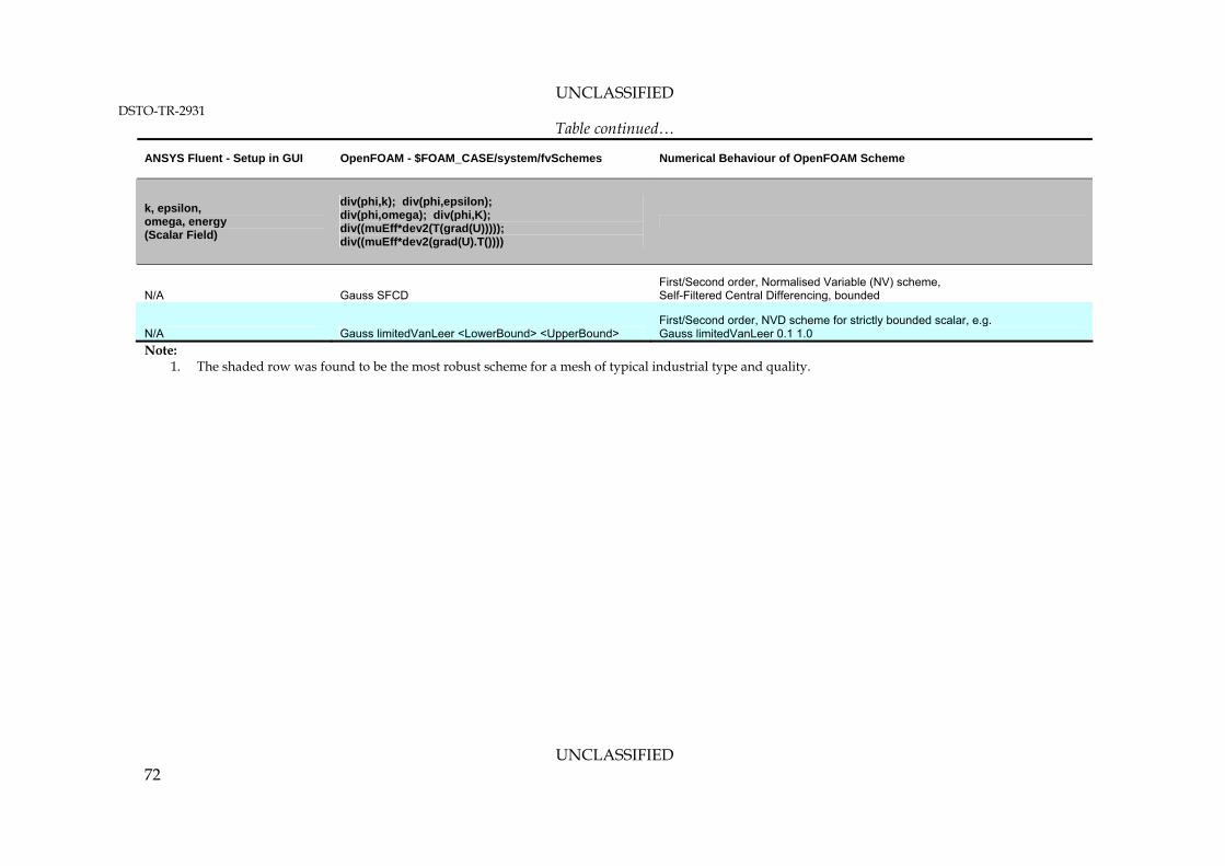
UNCLASSIFIED DSTO-TR-2931
UNCLASSIFIED 72
Table continued…
ANSYS Fluent - Setup in GUI OpenFOAM - $FOAM_CASE/system/fvSchemes Numerical Behaviour of OpenFOAM Scheme
k, epsilon, omega, energy (Scalar Field)
div(phi,k); div(phi,epsilon); div(phi,omega); div(phi,K); div((muEff*dev2(T(grad(U))))); div((muEff*dev2(grad(U).T())))
N/A Gauss SFCD First/Second order, Normalised Variable (NV) scheme, Self-Filtered Central Differencing, bounded
N/A Gauss limitedVanLeer <LowerBound> <UpperBound> First/Second order, NVD scheme for strictly bounded scalar, e.g. Gauss limitedVanLeer 0.1 1.0
Note: 1. The shaded row was found to be the most robust scheme for a mesh of typical industrial type and quality.

UNCLASSIFIED DSTO-TR-2931
UNCLASSIFIED 73
The central differencing interpolation (Gauss linear) used in the convective flux reconstruction is second order accurate, which often causes numerical oscillations during a steady RANS simulation. On the other hand, the upwind differencing scheme does not induce numerical oscillations, but is numerically very diffusive. Hence, a blend between the two schemes is the preferred method in most cases. The simplest method to blend the central differencing scheme with the upwind differencing scheme is by introducing a blending function into the interpolation scheme. This method is implemented in the Gauss linearUpwind scheme, which is similar to the ANSYS Fluent’s second order upwind discretisation scheme. Furthermore, there exist a large number of other flux reconstruction schemes, such as the TVD and NVD schemes, that attempt to apply various form of flux limiting schemes to increase the boundedness of the scheme. While these schemes may reduce numerical oscillations and at the same time achieve higher than first order accuracy, they have not been found to be significantly more robust than the linearUpwind scheme. It is also important to note that the overall accuracy of the Gauss schemes is limited to second order despite the use of higher order flux reconstruction schemes (i.e. Gauss cubicCorrected scheme will still be second order accurate despite the fourth order accurate interpolation scheme being used). Generally, in the author’s opinion, the bounded second order linearUpwind scheme with a faceLimited option provides an optimum balance between numerical stability and order of accuracy. However, for a strictly bounded scalar, such as turbulence kinetic energy, a vanLeer or limitedLinear TVD schemes may provide better damping to any numerical oscillation that may arise in the solution, particularly if strong gradients are expected to occur in the domain (Reference 18). All Laplacian terms have been excluded from Table 4.4 as there is no sufficient information available to deduce the type of Laplacian Schemes used in ANSYS Fluent. In OpenFOAM, a numerical scheme must be specified for all Laplacian terms found in the PDEs that are being solved. These are also specified in the “system/fvSchemes” file for each case. The Gauss scheme is the only choice of discretisation, and it requires a selection of both an interpolation scheme for the diffusion coefficient, and a surface normal gradient scheme. The following example illustrates the method of specifying a Laplacian discretisation scheme in OpenFOAM. Consider a typical Laplacian term found in the incompressible Navier-Stokes Equation,
U This is represented in OpenFOAM syntax as: laplacian(nu,U)

UNCLASSIFIED DSTO-TR-2931
UNCLASSIFIED 74
The Gauss scheme can be applied to the above Laplacian term by applying a divergence
scheme to the velocity gradient term, U . Note that the term U must be evaluated as a
surface normal gradient of velocity U at the face centre (in a similar fashion to the flux evaluation in the convection term). Thus, to summarise, the entries required are: laplacian(nu,U) Gauss <interpolationScheme> <snGradScheme>; The interpolation scheme can be chosen from those listed in Table 4.4. It is recommended that linear interpolation is used. The user must then specify the Surface Normal Gradient (snGrad) scheme from those listed in Table 4.5. Table 4.5: Surface normal gradient discretisation schemes for specifying Laplacian schemes in
OpenFOAM
OpenFOAM - $FOAM_CASE/system/fvSchemes Numerical Behaviour of OpenFOAM Scheme
snGrad Scheme
corrected Unbounded, second order, conservative
uncorrected Bounded, first order, non-conservative
limited <ψ>1 Blending of corrected and uncorrected schemes
bounded First order for bounded scalars ONLY
fourth Unbounded, fourth order, conservative
Note: 1. The shaded row was found to be the most robust for a mesh of typical industrial type and quality. The <ψ> corresponds to a floating point number between 0 and 1 (refer to the following paragraph for further explanation). The “corrected” and “fourth” snGrad schemes were found to induce numerical instability when used with an unstructured tetrahedral mesh. Therefore, it is recommended that the limited <ψ> scheme is used for most cases. According to Reference 13, the blending coefficient (0 ≤ ψ ≤ 1.0) for the limited scheme is based on the following criteria:
Selection of the appropriate blending coefficient to use should be based on the cell orthogonality measure. As a rule of thumb, when the maximum non-orthogonality in the mesh is found to be higher than 50°, the “Gauss linear limited 0.5” scheme should be used, and if the maximum cell non-orthogonality is found to be higher than 70°, the “Gauss linear limited 0.333” should be used. The simplest way to test the appropriateness of the choice of the Laplacian scheme is by running a potential flow solver (i.e. potentialFoam) using the prepared mesh. The
potentialFoam solves the potential flow equation ( 0.;02 Up ), which is the

UNCLASSIFIED DSTO-TR-2931
UNCLASSIFIED 75
Laplacian of the pressure (laplace(1,p) Gauss linear limited 0.5;). Thus, any numerical instability that arises during the potentialFoam simulation is solely due to the discretisation of the Laplacian term. A summary of the optimum second order discretisation schemes for running compressible flow cases typically considered within the IRSA group is shown in Table 4.6. Note that since the momentum source introduced by the rotorDiskSource library is an explicit source term, no additional discretisation scheme needs to be specified in the fvScheme file apart from those required by the solver. Table 4.6: Recommended second order accurate discretisation scheme set up for use with the
rhoSimpleFoam solver
Term / keyword in fvSchemes FV Scheme Comment
ddtSchemes
default steadyState; rhoSimpleFOAM compressible flow solver
gradSchemes
default cellLimited Gauss linear 1; Use "cellLimited Gauss pointLinear 1" if Mach > 0.5.
grad(U) cellLimited leastSquares 1; Cell-to-Cell flux limited to 1 neighbouring cell. LeastSquares fit interpolation.
grad(p) cellLimited Gauss linear 1; Can be changed to leastSquares if large number of highly non-orthogonal cells exist in the mesh.
grad(K) faceLimited Gauss linear 1; Cell-to-Face flux limited to 1 neighbouring cell. Linear interpolation (central differencing).
divSchemes
default none;
div(phi,U) Gauss linearUpwindV grad(U); grad(U) is the flux limited scheme - set in the gradSchemes.
div(U,p) Gauss linear; Use Gauss linear only to maintain accuracy for the pressure equation.
div(phi,k) Gauss limitedLinear 0.5; The coefficient "0.5" can be reduced to "0.1" to set the scheme closer to upwind behaviour. Gauss linearUpwind with flux limiter can also be used. Alternatively, use Gauss vanLeer.
div(phi,epsilon) Gauss limitedLinear 0.5; The coefficient "0.5" can be reduced to "0.1" to set the scheme closer to upwind behaviour. Gauss linearUpwind with flux limiter can also be used. Alternatively, use Gauss vanLeer.
Table continues over page…

UNCLASSIFIED DSTO-TR-2931
UNCLASSIFIED 76
Table continued…
Term / keyword in fvSchemes FV Scheme Comment
div(phi,omega) Gauss limitedLinear 0.5; The coefficient "0.5" can be reduced to "0.1" to set the scheme closer to upwind behaviour. Gauss linearUpwind with flux limiter can also be used. Alternatively, use Gauss vanLeer.
div(phi,K) Gauss linearUpwind grad(K); grad(K) is the flux limited scheme - set in the gradSchemes.
div(muEff*dev2(grad(U).T()))) Gauss linear; Use Gauss linear only to maintain accuracy for the turbulence modelling.
div(nuEff*dev(T(grad(U))))) Gauss linear; Use Gauss linear only to maintain accuracy for the turbulence modelling.
laplacianSchemes
default none; Default can be set to "Gauss linear limited 0.333". All the other Laplacian entries will be omitted.
laplacian(muEff,U) Gauss linear limited 0.333; Can be omitted if the default is used. It is recommended all laplacian terms used the same scheme.
laplacian((rho*(1/|A(U))),p) Gauss linear limited 0.333; Can be omitted if the default is used.
laplacian(alphaEff,h) Gauss linear limited 0.333; Can be omitted if the default is used.
laplacian(DkEff,k) Gauss linear limited 0.333; Can be omitted if the default is used.
laplacian(DepsilonEff,epsilon) Gauss linear limited 0.333; Can be omitted if the default is used.
laplacian(DomegaEff,omega) Gauss linear limited 0.333; Can be omitted if the default is used.
interpolationSchemes
default linear; upwind phi;
Can be changed to leastSquares for highly non-orthogonal mesh at a higher CPU cost. “upwind phi” scheme provides a bounded upwind interpolation.
snGradSchemes
default limited 0.333; flux limited scheme with non-orthogonal correction.
4.5.6 Selection of Linear Solvers
The type of linear solver used for solving each of the PDEs must be specified by the user in the “fvSolution” file located in the “system” directory of a case. Section 4.5 of Reference 13 contains some limited explanations on the setup of solution method for a

UNCLASSIFIED DSTO-TR-2931
UNCLASSIFIED 77
case. An example of the fvSolution file has also been included in the attached case files at Appendix B.2.15. There are several differences between the linear solver setup in OpenFOAM and ANSYS Fluent. ANSYS Fluent by default sets up the multigrid solver to be used for all PDEs. While, the same set up can also be used in an OpenFOAM case, it is not a recommended setting. Table 4.7 shows the recommended linear solver set up for a compressible OpenFOAM case. 4.5.7 Under-Relaxation Factors
Under-Relaxation Factors (URF) can be used to stabilise a steady-state RANS simulation run. In an OpenFOAM case, the URFs are setup in the “system/fvSolution” file under the keyword “relaxationFactors”. The most commonly accepted set of URFs as recommended in the ANSYS Fluent User Manual is to use a URF of 0.3 for pressure, and 0.7 for the momentum equation. Furthermore, ANSYS Fluent recommends using a URF ranging from 0.7 to 0.9 for the energy and turbulence model equations. This particular setup has been found to be unsuitable for running steady highly compressible flow cases in OpenFOAM. Severe numerical instability growth in the pressure field has been seen in the early iterations, which eventually led to numerical divergence. A recommended URF setup for running a steady compressible flow case using OpenFOAM is shown in Figure 4.15. The recommended URF for pressure is ranging between 0.001 and 0.1. Flow cases with higher Mach numbers will tend to require a lower URF for pressure during the early iterations (typically for the first 1000 – 2000 iterations). The URF for pressure may be increased in the later iterations to speed up convergence.
Figure 4.15: Recommended URF setup for running rhoSimpleSourceFoam solver for a moderately
compressible flow case

UNCLASSIFIED DSTO-TR-2931
UNCLASSIFIED 78
Table 4.7: Recommended linear Solver Set Up for Use with the rhoSimpleSourceFoam Solver
PDE Linear Solver Type
Recommended Setup (optimised)
Alternative Setups Comments
p
Preconditioned Conjugate Gradient Method (PCG)
p { solver PCG; preconditioner { preconditioner GAMG; tolerance 1e-05; relTol 1e-03; smoother DICGaussSeidel; nPreSweeps 0; nPostSweeps 2; nBottomSweeps 2; cacheAgglomeration false; nCellsInCoarsestLevel 20; agglomerator faceAreaPair; mergeLevels 1; } tolerance 1e-06; relTol 1e-02; }
p { solver GAMG; tolerance 1e-06; relTol 1e-02; smoother GaussSeidel; nPreSweeps 1; nPostSweeps 2; nBottomSweeps 2; cacheAgglomeration true; nCellsInCoarsestLevel 20; agglomerator faceAreaPair; mergeLevels 1; } ALTERNATIVELY p { solver PCG; // Use PBiCG for transonic preconditioner DIC; // Use DILU for transonic tolerance 1e-06; relTol 1e-02; }
The recommended setup uses the smoothed Geometric Algebraic Multi Grid (GAMG) solver as the matrix preconditioner for the PCG solver. This results in a highly optimised solution method for pressure as the GAMG preconditioner dramatically reduces the number of PCG iterations needed. However, the user may opt to use the GAMG as the main solver as a cheaper alternative. Another more expensive alternative would be to use the PCG solver with a Cholevsky method preconditioner (DIC). If the maximum Mach Number in the field is higher than 0.6, it is recommended that the 'transonic' options is enabled in the system/fvSolution file by adding the following entry: SIMPLE { transonic yes; } If the transonic option is enabled, the PBiCG solver must be used in place of PCG. The transonic option, when enabled, will write the p matrix in its full non-symmetric form. The PCG solver is only for solvng a symmetric matrix equation, while the PBiCG is the PCG counterpart for solving non-symmetric matrix equation.
Table continues over page…

UNCLASSIFIED DSTO-TR-2931
UNCLASSIFIED 79
Table continued…
PDE Linear Solver Type
Recommended Setup (optimised)
Alternative Setups Comments
U, h, k, epsilon, omega, R, nuTilda
Geometric Algebraic Multi Grid (GAMG) Solver
"(U|h|k|epsilon|omega|R|nuTilda)" { solver GAMG; tolerance 1e-08; relTol 1e-02; smoother GaussSeidel; nPreSweeps 1; nPostSweeps 2; nBottomSweeps 2; cacheAgglomeration true; nCellsInCoarsestLevel 20; agglomerator faceAreaPair; mergeLevels 1; }
"(U|h|k|epsilon|omega|R|nuTilda)" { solver smoothSolver; smoother GaussSeidel; tolerance 1e-08; relTol 1e-02; } ALTERNATIVELY "(U|h|k|epsilon|omega|R|nuTilda)" { solver PBiCG; smoother DILU; tolerance 1e-07; relTol 1e-02; }
It is recommended to use the the same solver type for U,h, k, epsilon, omega, and R. epsilon, omega, or R must be specified depending on the selection of turbulence model. Note that the expression "(U|h|k|epsilon|omega|R)" represents the boolean operation "or" wildcard. The recommended setup uses the GAMG solver with a GaussSeidel smoother. A cheaper alternative is to use the Gauss-Seidel solver (smoothSolver). Using the PBiCG is considered to be the most robust and accurate solution method, however at a higher computing cost. The Incomplete L-U Decomposition method (DILU) can be used as a preconditioner for the PBiCG solver. If any instability in the turbulence quantities develops during a simulation run, it is recommended to create a separate entry for "(k|epsilon|omega|R)", and using the smoothSolver for these PDEs.

UNCLASSIFIED DSTO-TR-2931
UNCLASSIFIED 80
4.6 Plotting Results on the Rotor Disk Surface using ParaviewTM
ParaviewTM is a third-party post-processing software that is included in the standard distribution of OpenFOAM. An extensive user guide is readily available from the Paraview official website at Reference 19. The discussion here will be limited to the important aspects of post-processing results generated using the rhoSimpleSourceFoam solver and the rotorDiskSource library. Readers are assumed to have a working knowledge of how to use Paraview’s basic functionality. As previously discussed in Section 4.3 and Section 4.4, the rotor disk surfaces are created using ANSYS TGrid as “interior” type surfaces. Since OpenFOAM does not recognise an interior type surface as a boundary condition, the rotor disk surfaces are translated into a “faceZone” during the mesh translation routine. Two methods are available in Paraview for plotting the flow-field variables on the rotor disk surface, i.e.: 1. By defining a new plane source7 in Paraview which has the same dimensions, position
and orientation as the rotor disk surface. This method can be difficult to implement if the exact position and orientation of the disk is unknown.
2. By converting the rotor disk region contained in the OpenFOAM mesh into a VTK format, which can then be readily read into Paraview. This is the preferred method, as the disk surface mesh and geometrical information preserved as a faceZone in the OpenFOAM mesh can then be read directly in the Paraview environment.
4.6.1 Plotting Flow-field Variables on the Rotor Disk using a New Plane Source in Paraview
After loading up the OpenFOAM case and data into Paraview, a new rotor disk surface plane can be defined in Paraview by selecting the following menu entry: Sources > Disk The dimensions, radial resolution and circumferential resolution of the newly created plane source must be set to correspond to the rotor disk mesh. Following this, the user must then apply a “transform” filter to the newly created disk to re-position and re-orient the disk to the correct location and orientation. This can be done through the following menu entry: Filters > Alphabetical > Transform
7 The term “source” in Paraview refers to a geometry definition (for example: a surface plane, cylinder, etc.) that is created exclusively within the Paraview environment.

UNCLASSIFIED DSTO-TR-2931
UNCLASSIFIED 81
Finally, the flow-field data can be mapped onto the newly created disk using the following menu entry: Filters > Alphabetical > Resample With Dataset Note that for the “Resample With Dataset” filter to work, the user must first select the main case name entry in the Selection Tree. 4.6.2 Plotting Flow-field Variables on the Rotor Disk using a VTK File
To use this method, the OpenFOAM mesh containing the rotor disk source region must first be exported into a VTK format. This can be done using the following command from the root directory of the corresponding OpenFOAM case: $ foamToVTK –latestTime The foamToVTK utility will write the mesh and point data into a new directory named VTK. Inside the VTK directory, each patch and faceZone is arranged into a separate directory. The user must then identify the name of the faceZone that corresponds to the rotor disk surface. The VTK file that is located inside the directory with the faceZone name contains the point and cell data for the corresponding faceZone surface. The newly created VTK file can be read into the Paraview environment using the standard “file > open” menu entry in Paraview, and can be subsequently used as the “source” for the “Resample With Dataset” filter as previously described in Section 4.6.1. This method is more efficient than the previous one as it does not require the user to know the exact position and orientation of the rotor disk surface.

UNCLASSIFIED DSTO-TR-2931
UNCLASSIFIED 82
5. Validation and Verification Test Case
5.1 Overview
An experimental dataset based on a rotor - fuselage aerodynamic interaction study is available from References 20 through 24. This dataset was identified as a suitable validation case for the rotorDiskSource model in OpenFOAM. The same case has been previously used by the ANSYS Fluent team at Reference 2 for validating the Fluent VBM model. The validation effort consists of modelling the wind tunnel experiment described in Reference 20 (which will be referred to hereafter as the Georgia Tech case) using both OpenFOAM and ANSYS Fluent. The results from both CFD packages will be compared to the experimental data. The OpenFOAM result will also be compared to the ANSYS Fluent result for verification purposes. The ANSYS Fluent VBM Model (version 9.0) provided by ANSYS directly (Reference 25) was used in this work. 5.2 Summary of Georgia Institute of Technology (Georgia Tech) Rotor-Airframe Interaction Experimental Setup
The wind tunnel experiment in Reference 20 involves placement of a simple fuselage body in a 2.3 m x 2.74 m low speed wind tunnel with a uniform freestream velocity. The tunnel freestream turbulence level was measured to be below 1 per cent. A two-bladed teetering rotor was placed above the fuselage to simulate a helicopter rotor. Using this setup, the rotor and the airframe were linked solely through the flow-field. Figure 5.1 shows a schematic of the experimental setup, which has been reproduced from Reference 20. According to References 20, 22 and 23, the fuselage geometry was a cylinder with a hemispherical nose. The cylinder diameter was 134 mm. The total length of the fuselage was 1,350 mm. The rotor hub was located 274.2 mm above the fuselage, and was placed along the fuselage symmetry line, at an axial length of 914 mm downstream from the fuselage nose tip. The rotor blade was made with an un-tapered NACA 0015 profile, with an 86 mm chord length. The rotor diameter was 914 mm. The blade hub diameter was 24.5 mm. The blade collective pitch angle was preset at 10 degrees during the experiment. The rotor plane was tilted at 6 degrees forward to simulate the forward flight condition, and the rotor speed was set at a constant 2100 rpm. In the experiment reported in Reference 22, the advance ratio (which is defined as the ratio of the tunnel freestream velocity to the rotor tip speed) was set to 0.10. This advance ratio was for a tunnel freestream velocity of 10 m/s. During the experiment, coning of the blade was measured to be negligible due to the stiffness of the blade and the absence of hinges at the rotor hub; however, the blade was free to flap laterally and longitudinally. The blade flapping angles were measured by

UNCLASSIFIED DSTO-TR-2931
UNCLASSIFIED 83
tracking the position of the blade tip. Reference 23 reported that the blade’s longitudinal and lateral flapping angles were 4.06 deg and 2.03 deg upwards respectively. The cylindrical fuselage in Reference 23 was instrumented with 94 static pressure taps. Furthermore, velocity field measurements at several locations in the flow-field were taken using the Laser Doppler Velocimetry (LDV) technique.
Figure 5.1: Georgia Tech rotor - airframe interaction wind tunnel experimental setup – reproduced
from Reference 23
5.3 CFD Model
5.3.1 Geometry and Mesh
A CFD model of the Georgia Tech experiment was created as part of the current validation effort. The geometry and mesh were created using the ANSYS Gambit and TGrid software. The mesh was then converted to an OpenFOAM mesh using the fluent3DMeshToFoam utility. Unstructured tetrahedral cells were used to mesh the entire computational domain, which comprises of approximately 1.4 million cells. The tetrahedral cells in the domain and on the fuselage wall were then converted to unstructured polyhedral cells to increase computational efficiency. The rotor domain mesh was of structured hexahedral type with approximately 30,000 cells. The computational domain was a 5.5m x 2.7m x 2.3m block.
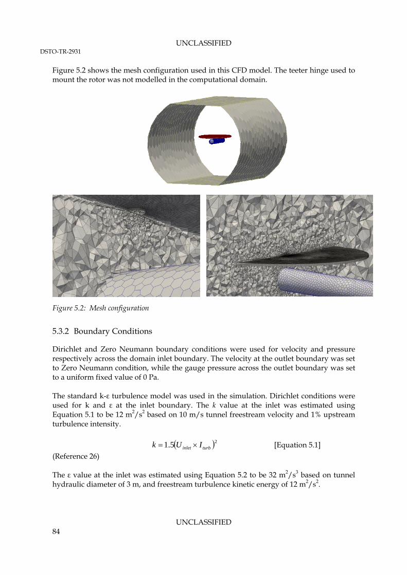
UNCLASSIFIED DSTO-TR-2931
UNCLASSIFIED 84
Figure 5.2 shows the mesh configuration used in this CFD model. The teeter hinge used to mount the rotor was not modelled in the computational domain.
Figure 5.2: Mesh configuration
5.3.2 Boundary Conditions
Dirichlet and Zero Neumann boundary conditions were used for velocity and pressure respectively across the domain inlet boundary. The velocity at the outlet boundary was set to Zero Neumann condition, while the gauge pressure across the outlet boundary was set to a uniform fixed value of 0 Pa. The standard k-ε turbulence model was used in the simulation. Dirichlet conditions were used for k and ε at the inlet boundary. The k value at the inlet was estimated using Equation 5.1 to be 12 m2/s2 based on 10 m/s tunnel freestream velocity and 1% upstream turbulence intensity.
25.1 turbinlet IUk [Equation 5.1]
(Reference 26) The ε value at the inlet was estimated using Equation 5.2 to be 32 m2/s3 based on tunnel hydraulic diameter of 3 m, and freestream turbulence kinetic energy of 12 m2/s2.

UNCLASSIFIED DSTO-TR-2931
UNCLASSIFIED 85
HD
kC
07.0
5.175.0 [Equation 5.2]
(Reference 26) where: HD is the tunnel hydraulic diameter,
C is a k-ε model constant (commonly accepted value is 0.09).
Zero Neumann conditions were used for k and ε at the outlet boundary. Non-slip wall conditions were used on all the domain boundaries except at the domain inflow and outflow boundaries. Zero Neumann conditions were used for pressure at walls, while the velocity is set to zero. The standard k and ε wall functions were used on all walls. The computed turbulent viscosity, ύ, was fitted with a standard wall function on the wall. The boundary condition set up for the Georgia Tech case is provided at Appendices B.2.6 through B.2.12. 5.3.3 Rotor Modelling
All of the rotor modelling parameters that are measured in the experiment (summarised in Section 5.2) can be incorporated into the VBM. It is important to point out that the pitch angle of the teetering rotor in the Georgia Tech experiment was fixed at 10° collective without any possibility of adjusting the cyclic pitch. The same collective pitch was entered as a rotor parameter in the VBM; however, the cyclic pitch has been assumed to be zero. The 2D lifting line and drag curves for the NACA 0015 airfoil were obtained from running a 2D panel method code called XFoil. The Cl and Cd profiles for a range of AOA are shown in Figure 5.3. 5.3.4 FV Discretisation Scheme and Linear Solvers
The same FV discretisation schemes as those presented in Table 4.6 were used to run the Georgia Tech case. The pressure equation was solved using the Geometric-Algebraic Multi Grid solver with a Gauss-Seidel smoother. All the other equations were solved using an iterative Gauss-Seidel method (smoothSolver). The iterative solver tolerances were set to 10-7 for the pressure solver, and 10-8 for all the other equations. An under relaxation factor of 0.2 was used for the pressure field during the simulation run. All other field variables were under-relaxed by a factor of 0.3 during runtime.

UNCLASSIFIED DSTO-TR-2931
UNCLASSIFIED 86
Samples of the FV discretisation scheme and linear solver setup for the Georgia Tech case are provided at Appendix B.2.14 and Appendix B.2.15 respectively.
Figure 5.3: Cl and Cd profiles for NACA 0015 airfoil over a range of AOA
5.3.5 ANSYS Fluent Case Setup
For verification purposes, an identical mesh and geometry to that used in OpenFOAM was setup and run using ANSYS Fluent. In ANSYS Fluent, the equations were initially discretised using first order upwind schemes. The schemes were later changed to second order upwind after 1000 iterations. The Multi-Grid solver was used for all equations in ANSYS Fluent. 5.3.6 Solution Driving Strategy and Residual Trend
The OpenFOAM case was initially run for 1000 iterations using the Gauss upwind (first order upwind) scheme for all the divergence terms. The schemes were then switched to

UNCLASSIFIED DSTO-TR-2931
UNCLASSIFIED 87
the Gauss linearUpwind (second order upwind) scheme from the 1000th iteration onwards, until convergence was achieved. The Flow-field convergence was observed after 4000 iterations. Figure 5.4 shows the residual curves for an OpenFOAM run of the untrimmed Georgia Tech case. The residuals are seen to exhibit cyclic behaviour at convergence, possibly due to some unsteadiness in the flow-field which cannot be modelled using the steady-state RANS model.
Figure 5.4: Residual curves of the Georgia Tech case run using the rhoSimpleSourceFoam solver
5.4 Verification and Validation Result
The Georgia Tech Rotor-Airframe experiment was simulated for both the untrimmed rotor and trimmed rotor conditions. In the untrimmed rotor simulation, the blade collective and cyclic pitch angles were set to the experimentally measured values. However, in the trimmed rotor simulation, the blade collective and cyclic pitch angles were allowed to change during the simulation until the experimentally measured total rotor thrust was obtained in the simulation. Due to the lack of data, the rotor pitching and rolling moments in the experiment were assumed to be zero for the trimmed rotor condition (See Section 5.4.3). 5.4.1 Calculated Rotor Thrust and Moments
A comparison between converged rotor disk thrust and moments obtained using different solvers is shown in Table 5.1. It shows that the predicted rotor thrust obtained using the simpleFoam (incompressible) solver for the untrimmed condition compares well with the

UNCLASSIFIED DSTO-TR-2931
UNCLASSIFIED 88
experimentally measured value of 72.8 N. The rhoSimpleFoam (compressible) solver and ANSYS Fluent are shown to under-predict the rotor thrust. Table 5.1: Calculated rotor thrust and moments
Total Rotor Disk
Flow Solver Untrimmed / Trimmed?
Blade Cyclic Pitch Angles
Blade Collective
Angle Thrust (N) Pitching Moment
(N.m)
Rolling Moment
(N.m)
Untrimmed 0° (Lat and
Long) 1
10° 1 71.96 2.72 -2.08
simpleFoam (Incompressible)
Trimmed 2.37° (Lat)
-2.88 (Long) 12° 72.8
2 0 0
Untrimmed 0° (Lat and
Long) 1
10° 1 66.93 2.46 -1.99
rhoSimpleSourceFoam (Compressible)
Trimmed 2.24° (Lat)
-2.54 (Long) 11.2° 72.8
2 0 0
ANSYS Fluent (Incompressible)
Untrimmed 0° (Lat and
Long) 1
10° 1 68.158 3.05 -3.32
Note:
1. Based on experimentally measured values (Reference 24).
2. Based on experimentally measured Coefficient of Thrust of 0.0092 (Reference 24).
5.4.2 Untrimmed Rotor Simulation Result
Pressure Field The mean static gauge pressure contour plots on the x-z plane and on the y-z plane passing through the rotor disk centre for the untrimmed rotor run are shown in Figure 5.5 and Figure 5.6 respectively. The figures show that the mean pressure field obtained using OpenFOAM and ANSYS Fluent compare favourably. Furthermore, result obtained using the modified OpenFOAM compressible flow solver (rhoSimpleSourceFoam) was also shown to be similar to that obtained using the incompressible flow solver (simpleFoam). From Figure 5.5, the effect of the forward tilt of the rotor disk plane is seen by the formation of a low pressure region at the forward tip of the rotor disk plane. Furthermore, Figure 5.6 shows that the lateral pressure distribution is not symmetrical although no lateral tilt is present on the rotor disk. The lateral pressure imbalance on the rotor disk is consistent with the predicted non-zero disk moments in the calculation. However, the actual rotor moments acting on the disk were not measured during these experiments; hence further comparison is prevented.

UNCLASSIFIED DSTO-TR-2931
UNCLASSIFIED 89
Figure 5.5: Mean static gauge pressure contour plot on the x-z plane which passes through the
rotor disk centre
ANSYS Fluent
simpleFOAM
rhoSimpleSourceFoam
Pa
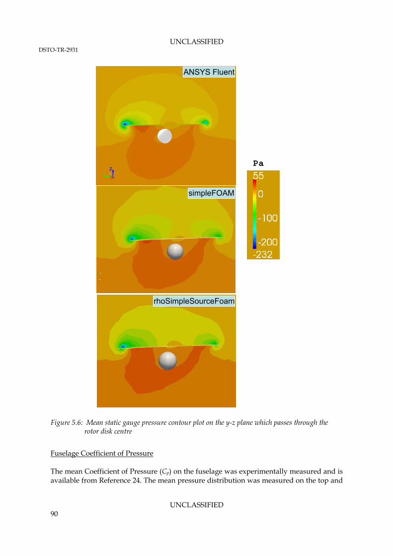
UNCLASSIFIED DSTO-TR-2931
UNCLASSIFIED 90
Figure 5.6: Mean static gauge pressure contour plot on the y-z plane which passes through the
rotor disk centre
Fuselage Coefficient of Pressure The mean Coefficient of Pressure (Cp) on the fuselage was experimentally measured and is available from Reference 24. The mean pressure distribution was measured on the top and
ANSYS Fluent
simpleFOAM
rhoSimpleSourceFoam
Pa

UNCLASSIFIED DSTO-TR-2931
UNCLASSIFIED 91
bottom surfaces, and on the port and starboard sides of the fuselage. Figure 5.7 shows the contour plot of Cp and pressure tapping locations on the fuselage. The Cp on the fuselage was defined as follows:
2
2
1
U
PPC wall
p
[Equation 5.3] (Reference 24)
Figure 5.7: Computed mean Cp on the fuselage without force and moment trimming
Figure 5.8 shows a comparison between the CFD computed Cp on the fuselage and the experimentally measured values. The comparison shows that the predicted Cp using both the OpenFOAM incompressible and compressible flow solvers compares favourably with the ANSYS Fluent’s prediction. However, both the OpenFOAM and ANSYS Fluent results have failed to capture the experimentally measured pressure peaks on the top and port sides of the fuselage. According to Reference 24, the disagreements in the pressure peaks occur at the locations where the blade tip vortices impinge on the fuselage body, as illustrated by the schematic shown at Figure 5.9. The momentum sources introduced by the VBM are based on time-averaged forces acting on the blade; thus, it cannot capture transient flow features, such as: formation of the blade tip vortices; and the effect of the blade passage as it moves through air. According to Reference 11, a possible explanation of the strong under-prediction of the pressure peak on the top surface of the fuselage near the nose is that it is due to the presence of a periodic tip vortex that retards the freestream airflow, causing a rise in the stagnation pressure at this location. Furthermore, although the blade thickness has been ignored in the present simulations, this may have a more pronounced effect on the pressure field when the blade is passing in
Note: The red and blue lines on the fuselage indicate locations of static pressure taps during the Georgia Tech experiment

UNCLASSIFIED DSTO-TR-2931
UNCLASSIFIED 92
close proximity to the fuselage surface. At this instance, the narrow space between the fuselage and the blade is expected to create a “venturi effect”, which causes local interaction between the rotor downwash and the freestream flow.
Figure 5.8: Comparison of measured and computed mean Cp on the fuselage without force and
moment trimming
Figure 5.9: Schematic representation of the instantaneous flow-field above the fuselage –
reproduced from Reference 22
-1
-0.5
0
0.5
1
1.5
0 0.5 1 1.5 2 2.5 3
Cp
-1.5
-1
-0.5
0
0.5
1
1.5
0 1 2 3
x/R
-0.5
0
0.5
1
1.5
2
0 0.5 1 1.5 2 2.5 3
Cp
-2
-1.5
-1
-0.5
0
0.5
1
1.5
0 1 2 3
x/R
Fuselage Top Fuselage Bottom
Fuselage Starboard Side Fuselage Port Side

UNCLASSIFIED DSTO-TR-2931
UNCLASSIFIED 93
A comparison between the gauge static pressure contour produced using ANSYS Fluent and the simpleFoam solver on the top surface of the rotor disk is shown in Figure 5.10. The same comparison for the rotor disk bottom surface is shown in Figure 5.11. These figures show that the pressure distribution patterns on the disk surfaces are generally similar in both the ANSYS Fluent and the OpenFOAM results. However, ANSYS Fluent predicts much lower pressure occurring on the front part of the disk compared to that shown in the OpenFOAM result.
Figure 5.10: Gauge static pressure contour on the rotor disk top surface
Figure 5.11: Gauge static pressure contour on the rotor disk bottom surface
Pa
ANSYS Fluent
simpleFoam
Pa
ANSYS Fluent
simpleFoam

UNCLASSIFIED DSTO-TR-2931
UNCLASSIFIED 94
Velocity Field Figure 5.12 shows a comparison between the flow streamlines coloured by velocity magnitude computed using OpenFOAM and ANSYS Fluent. It can be seen that the two results compare favourably to each other, albeit there are slight differences in the colour contrast and line thickness between the two results. There is no experimental data available that enables comparison with the streamlines. The “tip vortices” shown in Figure 5.12 are not the blade tip vortices; rather these are vortices that are formed due to the pressure gradient that exists between the top and bottom surfaces of the rotor disk, similar to those formed on the tip of a fixed wing. The comparison shows that generally the rotor flow is convected downstream by the freestream.
Figure 5.12: Streamlines coloured by velocity magnitude. Velocity magnitude contour plot is
shown on the rotor disk bottom surface
ANSYS Fluent
Mag(U)(m/s)
simpleFoam

UNCLASSIFIED DSTO-TR-2931
UNCLASSIFIED 95
Reference 20 provides the time-averaged measurement of the rotor downwash velocity normalised by the freestream velocity at a plane located 12.7 mm below the rotor disk. Contour plots of the rotor downwash velocity were generated from the CFD results to enable comparison with experimental data. This comparison is shown at Figure 5.13.
Figure 5.13: Contour plot of mean downwash velocity measured 12.7 mm below the rotor disk -
negative values denote upflow
Figure is reproduced from Reference 20
simpleFOAM
ANSYS Fluent
Uz/U(m/s)
FWD Side Aft Side

UNCLASSIFIED DSTO-TR-2931
UNCLASSIFIED 96
From Figure 5.13, the OpenFOAM result generally agrees very well with the experimentally measured values. The mean downwash velocity distribution is shown by both the CFD results and the experimental data to be asymmetrical with respect to the longitudinal axis. The upflow region near the hub is clearly seen on the retreating side of the rotor disk. There is also an upflow region observed in both results throughout the front part of the disk. According to Reference 20, the upflow region near the hub is largely attributed to the flow separation on the blade downstream of the hub, and the rotation imparted to the flow by the viscous effect near the hub. The strongest downwash flow is shown in both the experimental data and the OpenFOAM result to occur at around 70 and 290 rotor azimuth degrees towards the aft side of the disk, near the blade tip. The experimental data at Reference 20 includes a plot of the normalised velocity profile at a vertical location below the rotor disk, at z/R=0.178 (refer to Figure 5.14). The profile was measured along the fuselage body centreline axis. The same plot was constructed from the CFD results and compared to the available experimental data. This comparison is shown in Figure 5.15. From Figure 5.15, it can be seen that OpenFOAM under-predicts the streamwise velocity component compared to Fluent by approximately 14 per cent. However, there is a good agreement between the Fluent and OpenFOAM predicted downwash velocity profile, and the experimentally measured values.
Figure 5.14: Velocity measurement location at Reference 20
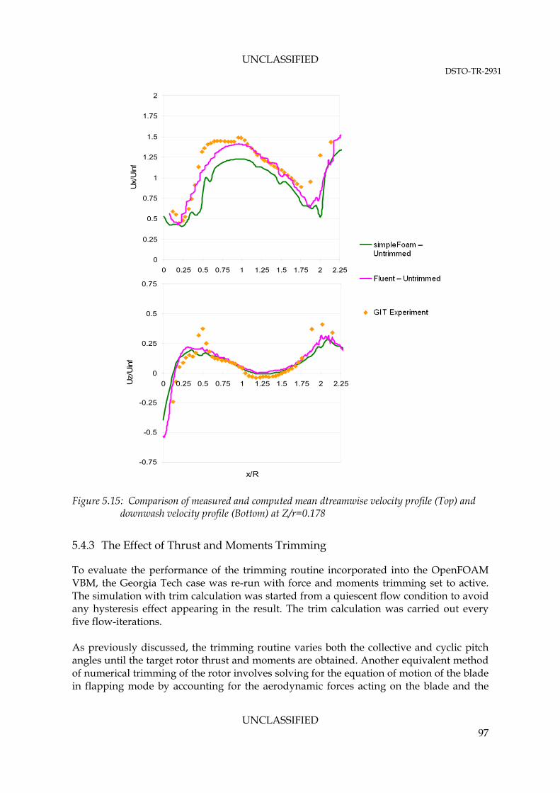
UNCLASSIFIED DSTO-TR-2931
UNCLASSIFIED 97
Figure 5.15: Comparison of measured and computed mean dtreamwise velocity profile (Top) and
downwash velocity profile (Bottom) at Z/r=0.178
5.4.3 The Effect of Thrust and Moments Trimming
To evaluate the performance of the trimming routine incorporated into the OpenFOAM VBM, the Georgia Tech case was re-run with force and moments trimming set to active. The simulation with trim calculation was started from a quiescent flow condition to avoid any hysteresis effect appearing in the result. The trim calculation was carried out every five flow-iterations. As previously discussed, the trimming routine varies both the collective and cyclic pitch angles until the target rotor thrust and moments are obtained. Another equivalent method of numerical trimming of the rotor involves solving for the equation of motion of the blade in flapping mode by accounting for the aerodynamic forces acting on the blade and the
0
0.25
0.5
0.75
1
1.25
1.5
1.75
2
0 0.25 0.5 0.75 1 1.25 1.5 1.75 2 2.25
Ux/
Uin
f
-0.75
-0.5
-0.25
0
0.25
0.5
0.75
0 0.25 0.5 0.75 1 1.25 1.5 1.75 2 2.25
x/R
Uz/
Uin
f
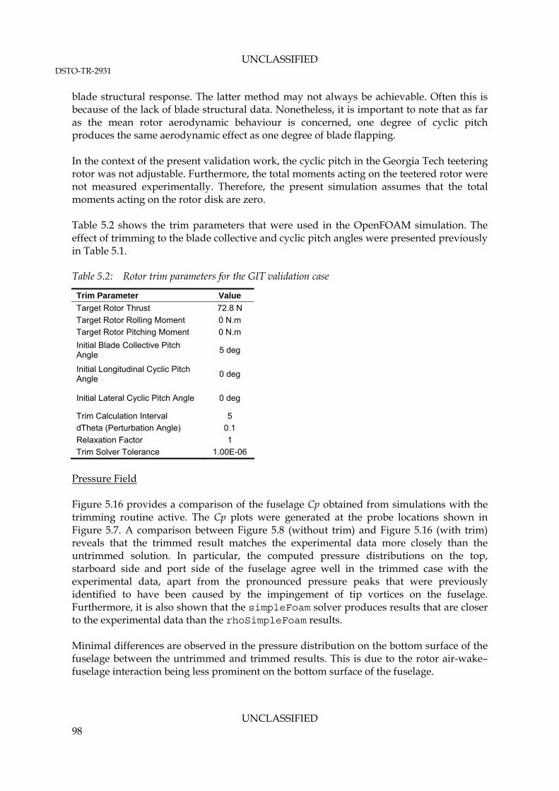
UNCLASSIFIED DSTO-TR-2931
UNCLASSIFIED 98
blade structural response. The latter method may not always be achievable. Often this is because of the lack of blade structural data. Nonetheless, it is important to note that as far as the mean rotor aerodynamic behaviour is concerned, one degree of cyclic pitch produces the same aerodynamic effect as one degree of blade flapping. In the context of the present validation work, the cyclic pitch in the Georgia Tech teetering rotor was not adjustable. Furthermore, the total moments acting on the teetered rotor were not measured experimentally. Therefore, the present simulation assumes that the total moments acting on the rotor disk are zero. Table 5.2 shows the trim parameters that were used in the OpenFOAM simulation. The effect of trimming to the blade collective and cyclic pitch angles were presented previously in Table 5.1. Table 5.2: Rotor trim parameters for the GIT validation case
Trim Parameter Value
Target Rotor Thrust 72.8 N
Target Rotor Rolling Moment 0 N.m
Target Rotor Pitching Moment 0 N.m
Initial Blade Collective Pitch Angle
5 deg
Initial Longitudinal Cyclic Pitch Angle
0 deg
Initial Lateral Cyclic Pitch Angle 0 deg
Trim Calculation Interval 5
dTheta (Perturbation Angle) 0.1
Relaxation Factor 1
Trim Solver Tolerance 1.00E-06
Pressure Field Figure 5.16 provides a comparison of the fuselage Cp obtained from simulations with the trimming routine active. The Cp plots were generated at the probe locations shown in Figure 5.7. A comparison between Figure 5.8 (without trim) and Figure 5.16 (with trim) reveals that the trimmed result matches the experimental data more closely than the untrimmed solution. In particular, the computed pressure distributions on the top, starboard side and port side of the fuselage agree well in the trimmed case with the experimental data, apart from the pronounced pressure peaks that were previously identified to have been caused by the impingement of tip vortices on the fuselage. Furthermore, it is also shown that the simpleFoam solver produces results that are closer to the experimental data than the rhoSimpleFoam results. Minimal differences are observed in the pressure distribution on the bottom surface of the fuselage between the untrimmed and trimmed results. This is due to the rotor air-wake– fuselage interaction being less prominent on the bottom surface of the fuselage.

UNCLASSIFIED DSTO-TR-2931
UNCLASSIFIED 99
Figure 5.16: Comparison of measured and computed mean Cp on the fuselage with the thrust and
moment trimming activated
Velocity Field The effect of thrust and moments trimming on the downwash velocity profile is shown in Figure 5.17. The figure shows that no significant improvement is gained by activating the thrust and moment trimming. However, the trim feature can be useful if the blade collective and cyclic pitch angles are not known, but the rotor disk total thrust and moments are known.
-1.5
-1
-0.5
0
0.5
1
1.5
0 0.5 1 1.5 2 2.5 3
x/R-2
-1.5
-1
-0.5
0
0.5
1
1.5
0 0.5 1 1.5 2 2.5 3
x/R
-1
-0.5
0
0.5
1
1.5
0 0.5 1 1.5 2 2.5 3
p
-0.5
0
0.5
1
1.5
2
0 0.5 1 1.5 2 2.5 3
p
Fuselage Top Fuselage Bottom
Fuselage Starboard Side Fuselage Port Side
Note: The blue dotted lines highlight the area of improvement whencompared to the plotted data shown previously in Figure 5.8.

UNCLASSIFIED DSTO-TR-2931
UNCLASSIFIED 100
Figure 5.17: Comparison of measured and computed streamwise velocity (Top) and downwash
velocity (Bottom) at Z/r=0.178 with the thrust and moment trimming activated
Tip Effect Figure 5.18 shows the effect of using a tip factor of 0.96 instead of 1.0 on the fuselage Cp, to account for the loss of lift near the blade tip. It can be seen from this figure that the predicted Cp trends on the fuselage top and port side surfaces have been slightly improved from the previous results shown in Figure 5.16. The value of 0.96 is considered to be typical. Therefore, it is recommended that a tip factor is specified in the simulation.
0
0.25
0.5
0.75
1
1.25
1.5
1.75
2
0 0.25 0.5 0.75 1 1.25 1.5 1.75 2 2.25
Ux/
Uin
f
-0.75
-0.5
-0.25
0
0.25
0.5
0.75
0 0.25 0.5 0.75 1 1.25 1.5 1.75 2 2.25
x/R
Uz/
Uin
f

UNCLASSIFIED DSTO-TR-2931
UNCLASSIFIED 101
Figure 5.18: Mean Cp on the fuselage with the thrust and moment trimming activated and using a
tip factor of 0.96
-0.5
0
0.5
1
1.5
2
0 0.5 1 1.5 2 2.5 3
p
-1.5
-1
-0.5
0
0.5
1
1.5
0 0.5 1 1.5 2 2.5 3
x/R
Fuselage Top
Fuselage Port Side

UNCLASSIFIED DSTO-TR-2931
UNCLASSIFIED 102
6. Conclusions and Recommendations
A new OpenFOAM library, rotorDiskSource, has been developed to include the effect of helicopter rotor flow into existing OpenFOAM steady-state RANS flow solvers. Being part of a free open-source software suite allows high performance computer cluster hardware to be used at minimum cost. This allows large-scale whole-of-airframe computations to be routinely made in support of accurate infrared signature modelling. In the new library, rotorDiskSource, the helicopter rotor is approximated as a thin one-cell-thick disk. The mean flow through the rotor is approximated by introducing time-averaged momentum sources on the rotor disk, which are calculated based on the two-dimensional Blade Element Theory. The rotorDiskSource model incorporates a range of blade characteristics, such as: the blade lifting line and drag profiles, variations in the blade collective and cyclic pitch angles, blade flapping and coning effect, as well as rotor thrust and moments trimming. Integration of the rotorDiskSource library into existing OpenFOAM RANS flow solvers has also been demonstrated. An experimental dataset based on a rotor - fuselage aerodynamic interaction study done at the Georgia Institute of Technology was identified as a suitable validation case for the rotorDiskSource model in OpenFOAM. The same case has been previously used by the ANSYS Fluent team at Reference 2 for validating the Fluent VBM model. The validation effort consists of modelling the Georgia Tech wind tunnel experiment using both OpenFOAM and ANSYS Fluent. The mean velocity and pressure fields predicted by both OpenFOAM and ANSYS Fluent software were shown to agree well with the time-averaged experimental data. However, both the OpenFOAM and ANSYS Fluent models failed to capture the effect of vortex shedding from the blade tip. Nonetheless, this shortcoming is to be expected from the current model, as only time-averaged momentum sources are being introduced on the rotor disk. The VBM is also not expected to capture any other transient flow features. Having completed validation, the rotorDiskSource library is being used to model the transport of the hot exhaust plume around various ADF helicopter types for a range of flight conditions. An example whole-of-aircraft flow-field prediction can be seen for the MRH-90 in Figure 6.1 and Figure 6.2. The details of these results and related modelling will be published in forthcoming DSTO reports.

UNCLASSIFIED DSTO-TR-2931
UNCLASSIFIED 103
Figure 6.1: Flow streamlines coloured by temperature used for visualising the interaction between
the exhaust plume and the rotor downwash around the MRH-90 in hover outside of ground effect.
Figure 6.2: Predicted MRH-90 fuselage temperature in hover with different prevailing relative
wind angles.
Note: Temperature is shown in Kelvin.
-150 Deg Wind (Portside)
-30 Deg Wind (Portside)
+150 Deg Wind (Starboard side)
+30 Deg Wind (Starboard side)
Note: 1. Temperature is shown in Kelvin. 2. The exhaust gas is visualised using iso-temperature contour plot. 3. The prevailing wind is relative to the aircraft heading.

UNCLASSIFIED DSTO-TR-2931
UNCLASSIFIED 104
7. References
1. Saripalli, S. R., “Virtual Blade Element Model Developments to Study Rotor Down Wash Effects (U)”, DSTO Technical Report, DSTO-TR-2311, June 2009.
2. Ruith, M. R., and Wirogo, S., “Unstructured, Multiplex Rotor Source Model with Thrust and Moment Trimming – Fluent’s VBE Model, AIAA 2005-5217, 23rd AIAA Applied Aerodynamics Conference, Toronto, Canada, 9 June 2005.
3. OpenCFD, http://www.openfoam.com, “OpenFOAM Official Website”, OpenFoam Foundation, ESI, Ltd., France.
4. Zori, L. A. J. and Rajagopalan, R. G., “Navier-Stokes Calculation of Rotor-Airframe Interaction in Forward Flight”, Journal of the American Helicopter Society, Vol. 40, Issue 2, 1995.
5. Wahono, S., “CFD Simulation of MRH-90 in Hover using OpenFOAM”, Draft DSTO Technical Report, TBA.
6. Advanced Rotorcraft Technology, Inc., “FlightLab”, Computer Software, March 2003.
7. Prouty, R. W., “Helicopter Aerodynamics”, Second Edition, Phillips Business information, Inc., 2007.
8. Rajagopalan, R. G. and Lim C. K., “Laminar Flow Analysis of a Rotor in Hover”, Journal of American Helicopter Society, Vol .36(1), 1991.
9. Rajagopalan, R. G. and Mahur, S. R., “Three Dimensional Analysis of a Rotor in Forward Flight”, Journal of American Helicopter Society, Vol. 38, Issue 3, 1993.
10. Poling D.R., Rosenstein H. and Rajagopalan R.G., “Use of a Navier-Stokes Code in Understanding Tiltrotor Flowfields in Hover”, Journal of American Helicopter Society, Vol.43, pp. 103-109, 1998.
11. Ruith, M. R., “Unstructured, Multiplex Rotor Source Model with Thrust and Moment Trimming – Fluent’s VBM Model”, Fluent Technical Notes, TN293, June 2005.
12. Johnson, W., “Helicopter Theory”, Dover Publications, 1994.
13. OpenCFD, “OpenFOAM User Guide”, Version 2.1.1, 16 May 2012.
14. OpenCFD, “OpenFOAM Programmer’s Guide”, Version 1.6, 24 July 2009.
15. OpenCFD, http://www.openfoam.org/docs/cpp/, “OpenFOAM Source Guide - Doxygen”, OpenFoam Foundation, ESI, Ltd., France.
16. Caretto, L. S., Gosman, A. D., Patankar, S. V., and Spalding, D. B., “Two Calculation Procedures for Steady, Three-Dimensional Flows with Recirculation, Proc. 3rd International Conferences for Numerical Methods in Fluid Dynamics, Paris, 1972.
17. Patankar, S. V., “Numerical Heat Transfer and Fluid Flow”, McGraw-Hill, New York, 1980.

UNCLASSIFIED DSTO-TR-2931
UNCLASSIFIED 105
18. Yee, C. S., Warming, R. F., and Harten, A., “Implicit Total Variation Diminishing (TVD) Schemes for Steady-State Calculations”, NASA Technical Memorandum, N83-23085, March 1983.
19. Kitware, Inc., http://paraview.org/paraview/help/documentation.html, “Paraview Official Website”.
20. Liou, S. G., Komerath, N. M., and McMahon, H. M., “Velocity Measurements of Airframe Effects on a Rotor in Low-Speed Forward Flight”, Journal of Aircraft, Vol. 26, Issue. 4, 1989.
21. Brand, A., Komerath, N. M., and McMahon, H. M., “Results from Laser Sheet Visualization of a Periodic Rotor Wake”, Journal of Aircraft, Vol. 26, Issue. 5, 1989.
22. Liou, S. G., Komerath, N. M., and McMahon, H. M., “Velocity Field of a Cylinder in the Wake of a Rotor in Forward Flight”, Journal of Aircraft, Vol. 27, Issue. 9, 1990.
23. Liou, S. G., Komerath, N. M., and McMahon, H. M., “Measurements of the Interaction Between a Rotor Tip Vortex and a Cylinder”, AIAA Journal, Vol. 28, Issue. 6, 1990.
24. Mavris, D. N., Komerath, N. M., and McMahon, H. M., “Prediction of Aerodynamic Rotor-Airframe Interactions in Forward Flight”, Journal of American Helicopter Society, October 1989.
25. Leap, Pty. Ltd., Fluent VBM UDF Version 9.0, Computer Code, Personal Communication via email, 5 January 2011.
26. OpenCFD, “OpenFOAM Andvanced Training Guide”, Version 1.6, 26 April 2010.

UNCLASSIFIED DSTO-TR-2931
UNCLASSIFIED 106
Appendix A Source Code for the rotorDiskSource
A.1. High Level Description of the Source Code Files
This Appendix contains the source code needed for the implementation of the VBM in OpenFOAM 2.1.x. The code needs to be compiled as an OpenFOAM library following the instructions given in Section 3.5. Table A.1 shows a complete list of all files included in the overall code along with a brief description of the content of each file. A hardcopy of all files is included in Section A.2 of this Appendix, arranged following the order shown in Table A.1. Comments in the code have been shown in blue to improve readability. Table A.1: Summary of all source files in the rotorDiskSource code
File Name Location Description rotorDiskSource.H rotorDiskSource Contains the class definition for the main
rotorDiskSource class. It is derived from the basicSource class.
rotorDiskSource.C rotorDiskSource Contains the main implementation of the rotorDiskSource Class. It contains the class constructor and several private member functions and implementation of the basicSource class virtual functions. The basic geometrical information of the rotor disk radius, centre, orientation, cell face areas are also subtracted from the mesh in this class. These procedures are contained in the following private functions: rotorDiskSource::createCoordinateSystem(), rotorDiskSource::constructGeometry(), and rotorDiskSource::setFaceArea(). The momentum source calculation is included in the member function rotorDiskSource::calculate(). The momentum source is added to the solver in the function rotorDiskSource::adSup().
rotorDiskSourceTemplates.C rotorDiskSource Contains a templated function rotorDiskSource::writeField() which can be used to write out to external data file any variable computed in the rotorDiskSource class as a field variable.
rotorDiskSourceI.H rotorDiskSource Contains the implementation of several data access functions as protected public member functions. These functions are handy for accessing and passing various protected and private data in the rotorDiskSource to any external classes.
Table continues over page …

UNCLASSIFIED DSTO-TR-2931
UNCLASSIFIED 107
Table continued … File Name Location Description rotorDiskSource.dep rotorDiskSource This file was automatically generated using the wmake
utility. It contains a list of all dependencies and their corresponding paths to the other standard OpenFOAM classes included in the OpenFOAM 2.1.x standard distribution.
bladeModel.H rotorDiskSource/ bladeModel
Contains the class definition of bladeModel class. This class is the container class for various blade geometry features as defined in the sourceProperties file, such as the blade radial section, twist angle and chord.
bladeModel.C rotorDiskSource/ bladeModel
Contains the constructor for bladeModel class and a linear interpolation function. Linear interpolation of the chord and twist angles between radial sections in the rotor disk is implemented in this class. This class is constructed in the Foam::rotorDiskSource class as a private object called “blade_”. The bladeModel::interpolate() function is called inside the rotorDiskSource::calculate() function.
profileModel.H rotorDiskSource/ profileModel
Contains the class definition of profileModel class. This class is the container class for various lifting and drag line profiles as defined in the sourceProperties file. The profileModel class is an abstract class for the two methods of specifying the blade section lift and drag coefficients curves, i.e. the “lookup” method and the “series” method.
profileModel.C rotorDiskSource/ profileModel
Contains the constructor for profileModel class and a virtual function, profileModel::Cdl() which calculates and returns the Cd and Cl for a given AOA. This class is constructed in the Foam::rotorDiskSource class as a private object called “profile_”. The profileModel::Cdl() function is called inside the rotorDiskSource::calculate() function.
profileModelList.H rotorDiskSource/ profileModel
Contains the class definition of profileModelList class. This class is derived from the template Foam::PtrList class which takes the profileModel class as its type.
profileModelList.C rotorDiskSource/ profileModel
Contains the constructor for profileModelList class and a virtual function, profileModelList::connectBlades() which sets the bladeModel – to - profileModel addressing.
Table continues over page …

UNCLASSIFIED DSTO-TR-2931
UNCLASSIFIED 108
Table continued … File Name Location Description lookupProfile.H rotorDiskSource/
profileModel/lookup Contains the class definition of lookupProfile class, which inherits from the abstract class Foam::profileModel. This class holds the Cd, Cl and AOA data. This class is only constructed during runtime if “lookup” entry is specified in the sourceProperties file.
lookupProfile.C rotorDiskSource/ profileModel/lookup
Contains the constructor for lookupProfile class and the implementation of the virtual function Foam::profileModel::Cdl(). This function looks-up the supplied Cl, Cd Vs AOA data from the sourceProperties file, and then linearly interpolates the Cl and Cd for a supplied AOA.
seriesProfile.H rotorDiskSource/ profileModel/series
Contains the class definition of seriesProfile class, which inherits from the abstract class Foam::profileModel. This class holds the Cd, Cl and AOA data. This class is only constructed during runtime if “series” entry is specified in the sourceProperties file.
seriesProfile.C rotorDiskSource/ profileModel/series
Contains the constructor for seriesProfile class and the implementation of the virtual function Foam::profileModel::Cdl(). This function reads the supplied coefficients for calculating Cl and Cd for a given AOA from the sourceProperties file, and then calculate the Cl and Cd based on the Fourier series equations specified in Section 3.4.1.
trimModel.H rotorDiskSource/ trimModel/ trimModel
Contains the class definition of trimModel class. This class is the container (abstract) class for various blade trimming methods as defined in the sourceProperties file. In the current implementation, there are two trimming methods available, i.e. the “fixed trim” and the “targetForce” trim. The default is fixed trim method, which is equivalent to an untrimmed solution.
trimModel.C rotorDiskSource/ trimModel/ trimModel
Contains the constructor for trimModel class and a virtual function, trimModel::correct(). This virtual function returns the updated blade forces when called using the new blade pitch parameters. This class is constructed in the Foam::rotorDiskSource class as a private object called “trim_”. . The trimModel::correct() function is called inside the rotorDiskSource::addSup() function.
Table continues over page …

UNCLASSIFIED DSTO-TR-2931
UNCLASSIFIED 109
Table continued … File Name Location Description trimModelNew.C rotorDiskSource/
trimModel/ trimModel
Contains a procedure to create “clones” of the trimModel class objects during runtime to account for multiple rotor objects.
fixedTrim.H rotorDiskSource/ trimModel/fixed
Contains the class definition of fixedTrim class, which inherits from the abstract class Foam::trimModel. This class reads blade collective and cyclic pitch angles from the sourceProperties file, and returns the geometric angle of attack. This class is only constructed during runtime if “fixed” trim entry is specified in the sourceProperties file.
fixedTrim.C rotorDiskSource/ trimModel/fixed
Contains the constructor for fixedTrim class and the implementation of the virtual functions Foam::trimModel::alphag() and Foam::trimModel::correct(). In this class, the Foam::trimModel::correct() function does nothing.
targetForceTrim.H rotorDiskSource/ trimModel/ targetForce
Contains the class definition of targetForceTrim class, which inherits from the abstract class Foam::trimModel. This class reads blade collective and cyclic pitch angles from the sourceProperties file, and returns the updated geometric angle of attack after a force and moments trimming calculation is carried out. This class is only constructed during runtime if “targetForce” trim entry is specified in the sourceProperties file.
targetForceTrim.C rotorDiskSource/ trimModel/ targetForce
Contains the constructor for targetForceTrim class and the implementation of the virtual functions Foam::trimModel::alphag() and Foam::trimModel::correct(). The implementation of the force and moments trimming using the Newton-Raphson method as described in Section 2.3.7 is contained in the Foam::targetForceTrim::correct() function inside this class.
files rotorDiskSource/ Make
Contains a list of .C files to be compiled using wmake libso. The compiled library name is also specified in this file.
Options rotorDiskSource/ Make
Contains a list of compiler options and include files to be included in the library compilation using wmake libso.

UNCLASSIFIED DSTO-TR-2931
UNCLASSIFIED 110
A.2. Source Code for the rotorDiskSource
A.2.1 rotorDiskSource.H
/*---------------------------------------------------------------------------*\ ========= | \\ / F ield | OpenFOAM: The Open Source CFD Toolbox \\ / O peration | \\ / A nd | Copyright (C) 2011-2012 OpenFOAM Foundation \\/ M anipulation | ------------------------------------------------------------------------------- License This file is part of OpenFOAM. OpenFOAM is free software: you can redistribute it and/or modify it under the terms of the GNU General Public License as published by the Free Software Foundation, either version 3 of the License, or (at your option) any later version. OpenFOAM is distributed in the hope that it will be useful, but WITHOUT ANY WARRANTY; without even the implied warranty of MERCHANTABILITY or FITNESS FOR A PARTICULAR PURPOSE. See the GNU General Public License for more details. You should have received a copy of the GNU General Public License along with OpenFOAM. If not, see <http://www.gnu.org/licenses/>. Class Foam::rotorDiskSource Description Cell based momentum source Source approximates the mean effects of rotor forces on a cylindrical region within the domain Sources described by: rotorDiskSourceCoeffs { fieldNames (U); // names of fields on which to apply source rhoName rho; // density field if compressible case nBlades 3; // number of blades tipEffect 0.96; // normalised radius above which lift = 0 inletFlowType local; // inlet flow type specification geometryMode auto; // geometry specification refDirection (-1 0 0); // reference direction // - used as reference for psi angle trimModel fixed; // fixed || targetForce flapCoeffs { beta0 0; // coning angle [deg] beta1 0; // lateral flapping coeff beta2 0; // longitudinal flapping coeff } blade { ... } profiles { ... } } Where: geometryMode = auto : determine rototor co-ord system from cells specified : specified co-ord system

UNCLASSIFIED DSTO-TR-2931
UNCLASSIFIED 111
inletFlowType = fixed : specified velocity surfaceNormal : specified normal velocity (positive towards rotor) local : use local flow conditions SourceFiles rotorDiskSource.C rotorDiskSourceTemplates.C \*---------------------------------------------------------------------------*/ #ifndef rotorDiskSource_H #define rotorDiskSource_H #include "basicSource.H" #include "cylindricalCS.H" #include "NamedEnum.H" #include "bladeModel.H" #include "profileModelList.H" #include "volFieldsFwd.H" #include "dimensionSet.H" // * * * * * * * * * * * * * * * * * * * * * * * * * * * * * * * * * * * * * // namespace Foam { // Forward declaration of classes class trimModel; /*---------------------------------------------------------------------------*\ Class rotorDiskSource Declaration \*---------------------------------------------------------------------------*/ class rotorDiskSource : public basicSource { public: enum geometryModeType { gmAuto, gmSpecified }; static const NamedEnum<geometryModeType, 2> geometryModeTypeNames_; enum inletFlowType { ifFixed, ifSurfaceNormal, ifLocal }; static const NamedEnum<inletFlowType, 3> inletFlowTypeNames_; protected: // Helper structures to encapsulate flap and trim data // Note: all input in degrees (converted to radians internally) struct flapData // on-the-fly data encapsulation declaration { scalar beta0; // coning angle scalar beta1; // lateral flapping coeff scalar beta2; // longitudinal flapping coeff }; // Protected data //- Name of density field word rhoName_; //- Reference density if rhoName = 'none' scalar rhoRef_;

UNCLASSIFIED DSTO-TR-2931
UNCLASSIFIED 112
//- Rotor debug mode bool rotorDebug_; //- Rotational speed [rad/s] // Positive anti-clockwise when looking along -ve lift direction scalar omega_; //- Number of blades label nBlades_; //- Inlet flow type inletFlowType inletFlow_; //- Inlet velocity for specified iinflow vector inletVelocity_; //- Tip effect [0-1] // Ratio of blade radius beyond which lift=0 scalar tipEffect_; //- Blade flap coefficients [rad/s] flapData flap_; //- Cell centre positions in local rotor frame // (Cylindrical r, theta, z) List<point> x_; //- Rotation tensor for flap angle List<tensor> R_; //- Inverse rotation tensor for flap angle List<tensor> invR_; //- Area [m2] List<scalar> area_; //- Rotor co-ordinate system (r, theta, z) cylindricalCS coordSys_; //- Maximum radius scalar rMax_; //- A list of psi angle in the rotor zone for IO List<scalar> psiList_; //- Trim model autoPtr<trimModel> trim_; //- Blade data bladeModel blade_; //- Profile data profileModelList profiles_; //- Rotor bank angle scalar bankAng_; //- Rotor pitch angle scalar pitchAng_; //- Transofrmation from Carteisan to Pitch/Bank plane tensor PB_; //- Transformation from Pitch Bank plane to Cartesian tensor invPB_; // Protected Member Functions //- Check data void checkData(); //- Set the face areas per cell, and optionally correct the rotor axis void setFaceArea(vector& axis, const bool correct); //- Create the co-ordinate system void createCoordinateSystem(); //- Construct geometry void constructGeometry();

UNCLASSIFIED DSTO-TR-2931
UNCLASSIFIED 113
//- Return the inlet flow-field tmp<vectorField> inflowVelocity(const volVectorField& U) const; //- Helper function to write rotor values template<class Type> void writeField ( const word& name, const List<Type>& values, const bool writeNow = false ) const; public: //- Runtime type information TypeName("rotorDisk"); // Constructors //- Construct from components rotorDiskSource ( const word& name, const word& modelType, const dictionary& dict, const fvMesh& mesh ); //- Destructor virtual ~rotorDiskSource(); // Member Functions // Access //- Return the cell centre positions in local rotor frame // (Cylindrical r, theta, z) inline const List<point>& x() const; //- Return the rotor co-ordinate system (r, theta, z) inline const cylindricalCS& coordSys() const; //- Return rhoName_ inline const word& getRhoName() const; //- Return rhoRef_ inline const scalar& getRhoRef() const; // Evaluation //- Calculate forces void calculate ( const vectorField& U, const scalarField& alphag, vectorField& force, const bool divideVolume = true, const bool output = true ) const; // Source term addition //- Source term to fvMatrix<vector> virtual void addSup(fvMatrix<vector>& eqn, const label fieldI); // I-O //- Write the source properties virtual void writeData(Ostream&) const; //- Read source dictionary virtual bool read(const dictionary& dict); };

UNCLASSIFIED DSTO-TR-2931
UNCLASSIFIED 114
// * * * * * * * * * * * * * * * * * * * * * * * * * * * * * * * * * * * * * // } // End namespace Foam // * * * * * * * * * * * * * * * * * * * * * * * * * * * * * * * * * * * * * // #include "rotorDiskSourceI.H" // * * * * * * * * * * * * * * * * * * * * * * * * * * * * * * * * * * * * * // #ifdef NoRepository #include "rotorDiskSourceTemplates.C" #endif // * * * * * * * * * * * * * * * * * * * * * * * * * * * * * * * * * * * * * // #endif // ************************************************************************* //

UNCLASSIFIED DSTO-TR-2931
UNCLASSIFIED 115
A.2.2 rotorDiskSource.C
/*---------------------------------------------------------------------------*\ ========= | \\ / F ield | OpenFOAM: The Open Source CFD Toolbox \\ / O peration | \\ / A nd | Copyright (C) 2011-2012 OpenFOAM Foundation \\/ M anipulation | ------------------------------------------------------------------------------- License This file is part of OpenFOAM. OpenFOAM is free software: you can redistribute it and/or modify it under the terms of the GNU General Public License as published by the Free Software Foundation, either version 3 of the License, or (at your option) any later version. OpenFOAM is distributed in the hope that it will be useful, but WITHOUT ANY WARRANTY; without even the implied warranty of MERCHANTABILITY or FITNESS FOR A PARTICULAR PURPOSE. See the GNU General Public License for more details. You should have received a copy of the GNU General Public License along with OpenFOAM. If not, see <http://www.gnu.org/licenses/>. \*---------------------------------------------------------------------------*/ #include "rotorDiskSource.H" #include "addToRunTimeSelectionTable.H" #include "mathematicalConstants.H" #include "trimModel.H" #include "unitConversion.H" #include "fvMatrices.H" #include "syncTools.H" using namespace Foam::constant; // * * * * * * * * * * * * * Static Member Functions * * * * * * * * * * * * // namespace Foam { defineTypeNameAndDebug(rotorDiskSource, 0); addToRunTimeSelectionTable(basicSource, rotorDiskSource, dictionary); template<> const char* NamedEnum<rotorDiskSource::geometryModeType, 2>:: names[] = { "auto", "specified" }; const NamedEnum<rotorDiskSource::geometryModeType, 2> rotorDiskSource::geometryModeTypeNames_; template<> const char* NamedEnum<rotorDiskSource::inletFlowType, 3>:: names[] = { "fixed", "surfaceNormal", "local" }; const NamedEnum<rotorDiskSource::inletFlowType, 3> rotorDiskSource::inletFlowTypeNames_; } // * * * * * * * * * * * * Protected Member Functions * * * * * * * * * * * // void Foam::rotorDiskSource::checkData() { // set inflow type switch (selectionMode()) { case smCellSet: case smCellZone: case smAll:

UNCLASSIFIED DSTO-TR-2931
UNCLASSIFIED 116
{ // set the profile ID for each blade section profiles_.connectBlades(blade_.profileName(), blade_.profileID()); switch (inletFlow_) { case ifFixed: { coeffs_.lookup("inletVelocity") >> inletVelocity_; break; } case ifSurfaceNormal: { scalar UIn ( readScalar(coeffs_.lookup("inletNormalVelocity")) ); inletVelocity_ = -coordSys_.e3()*UIn; break; } case ifLocal: { // do nothing break; } default: { FatalErrorIn("void rotorDiskSource::checkData()") << "Unknown inlet velocity type" << abort(FatalError); } } break; } default: { FatalErrorIn("void rotorDiskSource::checkData()") << "Source cannot be used with '" << selectionModeTypeNames_[selectionMode()] << "' mode. Please use one of: " << nl << selectionModeTypeNames_[smCellSet] << nl << selectionModeTypeNames_[smCellZone] << nl << selectionModeTypeNames_[smAll] << exit(FatalError); } } } void Foam::rotorDiskSource::setFaceArea(vector& axis, const bool correct) { area_ = 0.0; static const scalar tol = 0.8; const label nInternalFaces = mesh_.nInternalFaces(); const polyBoundaryMesh& pbm = mesh_.boundaryMesh(); const vectorField& Sf = mesh_.Sf(); const scalarField& magSf = mesh_.magSf(); vector n = vector::zero; // calculate cell addressing for selected cells labelList cellAddr(mesh_.nCells(), -1); UIndirectList<label>(cellAddr, cells_) = identity(cells_.size()); labelList nbrFaceCellAddr(mesh_.nFaces() - nInternalFaces, -1); // add internal field contributions for (label faceI = 0; faceI < nInternalFaces; faceI++) { const label own = cellAddr[mesh_.faceOwner()[faceI]]; const label nbr = cellAddr[mesh_.faceNeighbour()[faceI]]; if ((own != -1) && (nbr == -1)) { vector nf = Sf[faceI]/magSf[faceI]; if ((nf & axis) > tol) { area_[own] += magSf[faceI];

UNCLASSIFIED DSTO-TR-2931
UNCLASSIFIED 117
n += Sf[faceI]; } } else if ((own == -1) && (nbr != -1)) { vector nf = Sf[faceI]/magSf[faceI]; if ((-nf & axis) > tol) { area_[nbr] += magSf[faceI]; n -= Sf[faceI]; } } } forAll(pbm, patchI) { const polyPatch& pp = pbm[patchI]; if (pp.coupled()) { forAll(pp, i) { label faceI = pp.start() + i; label nbrFaceI = faceI - nInternalFaces; label own = mesh_.faceOwner()[faceI]; nbrFaceCellAddr[nbrFaceI] = cellAddr[own]; } } } // correct for parallel running syncTools::swapBoundaryFaceList(mesh_, nbrFaceCellAddr); // add boundary contributions forAll(pbm, patchI) { const polyPatch& pp = pbm[patchI]; const vectorField& Sfp = mesh_.Sf().boundaryField()[patchI]; const scalarField& magSfp = mesh_.magSf().boundaryField()[patchI]; if (pp.coupled()) { forAll(pp, j) { const label faceI = pp.start() + j; const label own = cellAddr[mesh_.faceOwner()[faceI]]; const label nbr = nbrFaceCellAddr[faceI - nInternalFaces]; const vector nf = Sfp[j]/magSfp[j]; if ((own != -1) && (nbr == -1) && ((nf & axis) > tol)) { area_[own] += magSfp[j]; n += Sfp[j]; } } } else { forAll(pp, j) { const label faceI = pp.start() + j; const label own = cellAddr[mesh_.faceOwner()[faceI]]; const vector nf = Sfp[j]/magSfp[j]; if ((own != -1) && ((nf & axis) > tol)) { area_[own] += magSfp[j]; n += Sfp[j]; } } } } if (correct) { reduce(n, sumOp<vector>()); axis = n/mag(n); } }

UNCLASSIFIED DSTO-TR-2931
UNCLASSIFIED 118
void Foam::rotorDiskSource::createCoordinateSystem() { // construct the local rotor co-prdinate system vector origin(vector::zero); vector axis(vector::zero); vector refDir(vector::zero); geometryModeType gm = geometryModeTypeNames_.read(coeffs_.lookup("geometryMode")); switch (gm) { case gmAuto: { // determine rotation origin (cell volume weighted) scalar sumV = 0.0; const scalarField& V = mesh_.V(); const vectorField& C = mesh_.C(); forAll(cells_, i) { const label cellI = cells_[i]; sumV += V[cellI]; origin += V[cellI]*C[cellI]; } reduce(origin, sumOp<vector>()); reduce(sumV, sumOp<scalar>()); origin /= sumV; // determine first radial vector vector dx1(vector::zero); scalar magR = -GREAT; forAll(cells_, i) { const label cellI = cells_[i]; vector test = C[cellI] - origin; if (mag(test) > magR) { dx1 = test; magR = mag(test); } } reduce(dx1, maxMagSqrOp<vector>()); magR = mag(dx1); // determine second radial vector and cross to determine axis forAll(cells_, i) { const label cellI = cells_[i]; vector dx2 = C[cellI] - origin; if (mag(dx2) > 0.5*magR) { axis = dx1 ^ dx2; if (mag(axis) > SMALL) { break; } } } reduce(axis, maxMagSqrOp<vector>()); axis /= mag(axis); // correct the axis direction using a point above the rotor { vector pointAbove(coeffs_.lookup("pointAbove")); vector dir = pointAbove - origin; dir /= mag(dir); if ((dir & axis) < 0) { axis *= -1.0; } } coeffs_.lookup("refDirection") >> refDir; // set the face areas and apply correction to calculated axis // e.g. if cellZone is more than a single layer in thickness setFaceArea(axis, true);

UNCLASSIFIED DSTO-TR-2931
UNCLASSIFIED 119
break; } case gmSpecified: { coeffs_.lookup("origin") >> origin; coeffs_.lookup("axis") >> axis; coeffs_.lookup("refDirection") >> refDir; setFaceArea(axis, false); break; } default: { FatalErrorIn("rotorDiskSource::createCoordinateSystem()") << "Unknown geometryMode " << geometryModeTypeNames_[gm] << ". Available geometry modes include " << geometryModeTypeNames_ << exit(FatalError); } } coordSys_ = cylindricalCS("rotorCoordSys", origin, axis, refDir, false); // BEWARE WHEN USING THIS cylindricalCS CLASS. IT IS INCOMPLETE! /* // ========== THIS METHOD RETURNS SEG FAULT ON MRH90 CASE ============= // // Calculate rotor pitch and bank angles from local co-ordinate system // normalised pitch-bank plane normal vector nNPB = coordSys_.e3()/mag(coordSys_.e3()); // Projection of normal onto cartesian Y-Z plane vector nPBYZ = vector(0, coordSys_.e3().y(), coordSys_.e3().z()); vector nNPBYZ = nPBYZ/mag(nPBYZ); // Projection of normal onto cartesian X-Z plane vector nPBXZ = vector(coordSys_.e3().x(), 0, coordSys_.e3().z()); vector nNPBXZ = nPBXZ/mag(nPBXZ); // Rotation of PB plane about X axis (bank angle) bankAng_ = -acos(nNPB & nNPBYZ)*(coordSys_.e3().y()/mag(coordSys_.e3().y())); // Rotation of PB plane about Y axis (pitch angle) pitchAng_ = acos(nNPB & nNPBXZ)*(coordSys_.e3().x()/mag(coordSys_.e3().x())); */ // ======================================================================== // // alternative way of calculating pitch and bank angles bankAng_ = atan2(coordSys_.e3().y(), coordSys_.e3().z()); pitchAng_ = atan2(coordSys_.e3().x(), coordSys_.e3().z()); // Tensor for transforming from Cartesian into Pitch/Bank Plane scalar cp = cos(pitchAng_); scalar sp = sin(pitchAng_); scalar cb = cos(bankAng_); scalar sb = sin(bankAng_); PB_ = tensor(cp, sp*sb, sp*cb, 0, cb, -sb, -sp, cp*sb, cp*cb); /* // Alternative way of constructing the rotational tensor scalar cp = cos(pitchAng_); scalar sp = sin(pitchAng_); scalar cb = cos(-bankAng_); scalar sb = sin(-bankAng_); // rotation tensor about the cartesian X-Axis by bankAng_ tensor bankRotate = tensor(1, 0, 0, 0, cb, sb, 0, -sb, cb); // rotation tensor about the cartesian Y-axis by pitchAng_ tensor pitchRotate = tensor(cp, 0, -sp, 0, 1, 0, sp, 0, cp); // combined bank and pitch rotations PB_ = pitchRotate * bankRotate; // manual check of the combined rotational tensor //PB_ = tensor(cp, -sp*sb, -sp*cb, 0, cb, -sb, sp, cp*sb, cp*cb); */ // Tensor for transforming from Pitch/Bank Plane into Cartesian invPB_ = PB_.T();

UNCLASSIFIED DSTO-TR-2931
UNCLASSIFIED 120
const scalar sumArea = gSum(area_); const scalar diameter = Foam::sqrt(4.0*sumArea/mathematical::pi); Info<< " =================================== " << nl << " # Using rotorDiskSource 20120822 # " << nl << " =================================== " << nl << endl; Info<< " Rotor gometry:" << nl << " - disk diameter = " << diameter << nl << " - disk area = " << sumArea << nl << " - origin = " << coordSys_.origin() << nl << " - r-axis = " << coordSys_.e1() << nl << " - psi-axis = " << coordSys_.e2() << nl << " - z-axis = " << coordSys_.e3() << nl << " - disk pitch angle = " << pitchAng_ << nl << " - disk bank angle = " << bankAng_ << endl; } void Foam::rotorDiskSource::constructGeometry() { const vectorField& C = mesh_.C(); forAll(cells_, i) { if (area_[i] > ROOTVSMALL) { const label cellI = cells_[i]; // position in (planar) rotor co-ordinate system x_[i] = coordSys_.localPosition(C[cellI]); // cache max radius rMax_ = max(rMax_, x_[i].x()); // swept angle relative to rDir axis [radians] in range 0 -> 2*pi scalar psi = x_[i].y(); if (rotorDebug_) { psiList_[i] = radToDeg(psi); } // blade flap angle [radians] scalar beta = flap_.beta0 - flap_.beta1*cos(psi) - flap_.beta2*sin(psi); // determine rotation tensor to convert from planar system into the // rotor cone system scalar c = cos(beta); scalar s = sin(beta); R_[i] = tensor(c, 0, -s, 0, 1, 0, s, 0, c); invR_[i] = R_[i].T(); } } // reduce rMax_ for parallel running reduce(rMax_, maxOp<scalar>()); } Foam::tmp<Foam::vectorField> Foam::rotorDiskSource::inflowVelocity ( const volVectorField& U ) const { switch (inletFlow_) { case ifFixed: case ifSurfaceNormal: { return tmp<vectorField> ( new vectorField(mesh_.nCells(), inletVelocity_) ); break; } case ifLocal: { return U.internalField();

UNCLASSIFIED DSTO-TR-2931
UNCLASSIFIED 121
break; } default: { FatalErrorIn ( "Foam::tmp<Foam::vectorField> " "Foam::rotorDiskSource::inflowVelocity" "(const volVectorField&) const" ) << "Unknown inlet flow specification" << abort(FatalError); } } return tmp<vectorField>(new vectorField(mesh_.nCells(), vector::zero)); } // * * * * * * * * * * * * * * * Constructors * * * * * * * * * * * * * * * // Foam::rotorDiskSource::rotorDiskSource ( const word& name, const word& modelType, const dictionary& dict, const fvMesh& mesh ) : basicSource(name, modelType, dict, mesh), rhoName_("none"), rhoRef_(1.2), rotorDebug_(false), omega_(0.0), nBlades_(0), inletFlow_(ifLocal), inletVelocity_(vector::zero), tipEffect_(1.0), flap_(), x_(cells_.size(), vector::zero), R_(cells_.size(), I), invR_(cells_.size(), I), area_(cells_.size(), 0.0), coordSys_(false), rMax_(0.0), psiList_(cells_.size(), 0.0), trim_(trimModel::New(*this, coeffs_)), blade_(coeffs_.subDict("blade")), profiles_(coeffs_.subDict("profiles")) { read(dict); } // * * * * * * * * * * * * * * * * Destructor * * * * * * * * * * * * * * * // Foam::rotorDiskSource::~rotorDiskSource() {} // * * * * * * * * * * * * * * * Member Functions * * * * * * * * * * * * * // void Foam::rotorDiskSource::calculate ( const vectorField& U, const scalarField& alphag, vectorField& force, const bool divideVolume, const bool output ) const { const vectorField& C = mesh_.C(); const scalarField& V = mesh_.V(); const bool compressible = rhoName_ != "none"; tmp<volScalarField> trho ( compressible ? mesh_.lookupObject<volScalarField>(rhoName_) : volScalarField::null() );

UNCLASSIFIED DSTO-TR-2931
UNCLASSIFIED 122
// logging info scalar dragEff = 0.0; scalar liftEff = 0.0; scalar AOAmin = GREAT; scalar AOAmax = -GREAT; scalar epsMin = GREAT; scalar epsMax = -GREAT; scalar CdMin = 10.0; scalar CdMax = VSMALL; scalar ClMin = 10.0; scalar ClMax = VSMALL; scalar totalThrust = 0.0; scalar totalPitchingMoment = 0.0; scalar totalRollingMoment = 0.0; // begin looping over all rotor cells forAll(cells_, i) { if (area_[i] > ROOTVSMALL) { const label cellI = cells_[i]; const scalar radius = x_[i].x(); const scalar psi = x_[i].y(); // velocity in local cylindrical reference frame // the localVector function below is just for position vector. //vector Uc = coordSys_.localVector(U[cellI]); // velocity in local cylindrical reference frame // This assumes that the Uz is the same as the rotorDiskPlane normal axis. // aligning U to the pitch bank angle plane vector Upb = PB_ & U[cellI]; vector Uc = vector ( Upb.x()*cos(psi)+Upb.y()*sin(psi), -Upb.x()*sin(psi)+Upb.y()*cos(psi), Upb.z() ); /* // transforming velocity to rotor local cylindrical frame // using the dot products of the two systems' base vectors const vector e1Global = vector (1, 0, 0); const vector e2Global = vector (0, 1, 0); const vector e3Global = vector (0, 0, 1); vector Uc = vector (0, 0, 0); Uc.x() = U[cellI].x() * (coordSys_.e1() & e1Global) + U[cellI].y() * (coordSys_.e2() & e1Global) + U[cellI].z() * (coordSys_.e3() & e1Global); Uc.y() = U[cellI].x() * (coordSys_.e1() & e2Global) + U[cellI].y() * (coordSys_.e2() & e2Global) + U[cellI].z() * (coordSys_.e3() & e2Global); Uc.z() = U[cellI].x() * (coordSys_.e1() & e3Global) + U[cellI].y() * (coordSys_.e2() & e3Global) + U[cellI].z() * (coordSys_.e3() & e3Global); // ==> This method does not work because the coordSys_.e1(), e2() // and e3() does not return the base vectors of r, psi, z in terms of // i, j, k for each cell. In fact only e3() vector is correct. // e1() and e2() were found to not vary with cell position. */ // transform from rotor cylindrical into local coning system Uc = R_[i] & Uc; // set radial component of velocity to zero Uc.x() = 0.0; // total Utheta //scalar Ut = radius*omega_ + Uc.y(); // set blade normal component of velocity Uc.y() = radius*omega_ - Uc.y();

UNCLASSIFIED DSTO-TR-2931
UNCLASSIFIED 123
// air angle (rad) //scalar eps = atan2(Uc.z(), fabs(Ut)); scalar eps = atan2(-Uc.z(), Uc.y()); if (eps < -mathematical::pi) { eps = (2.0*mathematical::pi + eps); } if (eps > mathematical::pi) { eps = (eps - 2.0*mathematical::pi); } epsMin = min(epsMin, eps); epsMax = max(epsMax, eps); // determine blade data for this radius // i2 = index of upper radius bound data point in blade list scalar twist = 0.0; scalar chord = 0.0; label i1 = -1; label i2 = -1; scalar invDr = 0.0; blade_.interpolate(radius, twist, chord, i1, i2, invDr); // flip geometric angle if blade is spinning in reverse (clockwise) scalar alphaGeom = alphag[i] + twist; if (omega_ < 0) { alphaGeom = mathematical::pi - alphaGeom; } // effective angle of attack scalar alphaEff = alphaGeom - atan2(-Uc.z(), Uc.y()); if (alphaEff < -mathematical::pi) { alphaEff = (2.0*mathematical::pi + alphaEff); } if (alphaEff > mathematical::pi) { alphaEff = (alphaEff - 2.0*mathematical::pi); } AOAmin = min(AOAmin, alphaEff); AOAmax = max(AOAmax, alphaEff); // determine profile data for this radius and angle of attack const label profile1 = blade_.profileID()[i1]; const label profile2 = blade_.profileID()[i2]; scalar Cd1 = 0.0; scalar Cl1 = 0.0; profiles_[profile1].Cdl(alphaEff, Cd1, Cl1); scalar Cd2 = 0.0; scalar Cl2 = 0.0; profiles_[profile2].Cdl(alphaEff, Cd2, Cl2); scalar Cd = invDr*(Cd2 - Cd1) + Cd1; scalar Cl = invDr*(Cl2 - Cl1) + Cl1; CdMin = min(CdMin, fabs(Cd)); CdMax = max(CdMax, fabs(Cd)); ClMin = min(ClMin, fabs(Cl)); ClMax = max(ClMax, fabs(Cl)); // apply tip effect for blade lift scalar tipFactor = 1.0; if ((radius/rMax_) > tipEffect_) { tipFactor = 0.0; } //scalar tipFactor = neg(radius/rMax_ - tipEffect_); // calculate forces perpendicular to blade scalar pDyn = 0.5*magSqr(Uc); if (compressible)

UNCLASSIFIED DSTO-TR-2931
UNCLASSIFIED 124
{ pDyn *= trho()[cellI]; } scalar f = pDyn*chord*nBlades_*area_[i]/radius/mathematical::twoPi; // forces in blade coordinate system //scalar ftc = (f*Cd*cos(eps) - tipFactor*f*Cl*sin(eps)); //scalar fnc = (f*Cd*sin(eps) + tipFactor*f*Cl*cos(eps)); // Implementation of Kim et al [7th OpenFOAM Workshop] scalar ftc = (f*Cd*cos(eps) + tipFactor*f*Cl*sin(eps)); scalar fnc = (-f*Cd*sin(eps) + tipFactor*f*Cl*cos(eps)); //vector localForce = vector(0.0, -f*Cd, tipFactor*f*Cl); vector localForce = vector(0.0, -ftc, fnc); if (compressible) { // accumulate forces dragEff += localForce.y(); liftEff += localForce.z(); } else { dragEff += rhoRef_*localForce.y(); liftEff += rhoRef_*localForce.z(); } if (rotorDebug_) { if (i == 0) { Info << "CellI psi radius alphaEff " << "eps Cl Cd f fn fth" << nl << endl; } Info << cellI << " " << psiList_[cellI] << " " << radius << " " << radToDeg(alphaEff) << " " << radToDeg(eps) << " " << Cl << " " << Cd << " " << f << " " << localForce.y() << " " << localForce.z() << endl; } // convert force from local coning system into rotor cylindrical localForce = invR_[i] & localForce; // convert force to global cartesian co-ordinate system // similarly to the localVector function, the globalVector is // only meant for the position vector. //force[cellI] = coordSys_.globalVector(localForce); // convert force to global cartesian co-ordinate system // the line below assumes that there is zero tilt on the rotorDiskPlane localForce = vector ( localForce.x()*cos(psi) - localForce.y()*sin(psi), localForce.x()*sin(psi) + localForce.y()*cos(psi), localForce.z() ); force[cellI] = invPB_ & localForce; /* // transforming force from rotor local cylindrical to global cartesian // using the dot products of the two systems' base vectors vector globalForce = vector (0, 0, 0); globalForce.x() = localForce.x() * (coordSys_.e1() & e1Global) + localForce.y() * (coordSys_.e2() & e1Global) + localForce.z() * (coordSys_.e3() & e1Global); globalForce.y() = localForce.x() * (coordSys_.e1() & e2Global) + localForce.y() * (coordSys_.e2() & e2Global) + localForce.z() * (coordSys_.e3() & e2Global); globalForce.z() = localForce.x() * (coordSys_.e1() & e3Global) + localForce.y() * (coordSys_.e2() & e3Global) + localForce.z() * (coordSys_.e3() & e3Global);

UNCLASSIFIED DSTO-TR-2931
UNCLASSIFIED 125
force[cellI] = globalForce; // ==> This method does not work because the coordSys_.e1(), e2() // and e3() does not return the base vectors of r, psi, z in terms of // i, j, k for each cell. In fact only e3() vector is correct. // e1() and e2() were found to not vary with cell position. */ if (compressible) { // calculate global thrust and moment vector moment = force[cellI]^(C[cellI] - coordSys_.origin()); totalThrust += force[cellI] & coordSys_.e3(); totalPitchingMoment += moment & coordSys_.e2(); totalRollingMoment += moment & coordSys_.e1(); } else { vector moment = force[cellI]^(C[cellI] - coordSys_.origin()); totalThrust += (rhoRef_ * (force[cellI] & coordSys_.e3())); totalPitchingMoment += (rhoRef_ * (moment & coordSys_.e2())); totalRollingMoment += (rhoRef_ * (moment & coordSys_.e1())); } if (divideVolume) { // calculate momentum source force[cellI] /= V[cellI]; } } } if (output) { reduce(AOAmin, minOp<scalar>()); reduce(AOAmax, maxOp<scalar>()); reduce(epsMin, minOp<scalar>()); reduce(epsMax, maxOp<scalar>()); reduce(dragEff, sumOp<scalar>()); reduce(liftEff, sumOp<scalar>()); reduce(totalThrust, sumOp<scalar>()); reduce(totalPitchingMoment, sumOp<scalar>()); reduce(totalRollingMoment, sumOp<scalar>()); Info<< type() << " output:" << nl << " min/max(AOA) = " << radToDeg(AOAmin) << ", " << radToDeg(AOAmax) << nl << " min/max(induced AOA) = " << radToDeg(epsMin) << ", " << radToDeg(epsMax) << nl << " Effective blade drag = " << dragEff << nl << " Effective blade lift = " << liftEff << nl << " Total Thrust = " << totalThrust << nl << " Total Pitching Moment = " << totalPitchingMoment << nl << " Total Rolling Moment = " << totalRollingMoment << endl; } } void Foam::rotorDiskSource::addSup(fvMatrix<vector>& eqn, const label fieldI) { dimensionSet dims = dimless; if (eqn.dimensions() == dimForce) { coeffs_.lookup("rhoName") >> rhoName_; dims.reset(dimForce/dimVolume); } else { coeffs_.lookup("rhoRef") >> rhoRef_; dims.reset(dimForce/dimVolume/dimDensity); } volVectorField force ( IOobject ( "rotorForce", mesh_.time().timeName(), mesh_, IOobject::NO_READ,

UNCLASSIFIED DSTO-TR-2931
UNCLASSIFIED 126
IOobject::NO_WRITE ), mesh_, dimensionedVector("zero", dims, vector::zero) ); const volVectorField& U = eqn.psi(); const vectorField Uin = inflowVelocity(U); trim_->correct(Uin, force); calculate(Uin, trim_->alphag(), force); // add source to rhs of eqn eqn += -force; if (mesh_.time().outputTime()) { force.write(); } } void Foam::rotorDiskSource::writeData(Ostream& os) const { os << indent << name_ << endl; dict_.write(os); } bool Foam::rotorDiskSource::read(const dictionary& dict) { if (basicSource::read(dict)) { coeffs_.lookup("fieldNames") >> fieldNames_; applied_.setSize(fieldNames_.size(), false); // read if rotorDebug is active coeffs_.lookup("rotorDebugMode") >> rotorDebug_; // read co-ordinate system/geometry invariant properties scalar rpm(readScalar(coeffs_.lookup("rpm"))); omega_ = rpm/60.0*mathematical::twoPi; coeffs_.lookup("nBlades") >> nBlades_; inletFlow_ = inletFlowTypeNames_.read(coeffs_.lookup("inletFlowType")); coeffs_.lookup("tipEffect") >> tipEffect_; const dictionary& flapCoeffs(coeffs_.subDict("flapCoeffs")); flapCoeffs.lookup("beta0") >> flap_.beta0; flapCoeffs.lookup("beta1") >> flap_.beta1; flapCoeffs.lookup("beta2") >> flap_.beta2; flap_.beta0 = degToRad(flap_.beta0); flap_.beta1 = degToRad(flap_.beta1); flap_.beta2 = degToRad(flap_.beta2); // create co-ordinate system createCoordinateSystem(); // read co-odinate system dependent properties checkData(); constructGeometry(); // reading rhoName_ coeffs_.lookup("rhoName") >> rhoName_; coeffs_.lookup("rhoRef") >> rhoRef_; trim_->read(coeffs_); if (debug) { writeField("alphag", trim_->alphag()(), true); writeField("faceArea", area_, true); }

UNCLASSIFIED DSTO-TR-2931
UNCLASSIFIED 127
return true; } else { return false; } } // ************************************************************************* //

UNCLASSIFIED DSTO-TR-2931
UNCLASSIFIED 128
A.2.3 rotorDiskSourceTemplates.C
/*---------------------------------------------------------------------------*\ ========= | \\ / F ield | OpenFOAM: The Open Source CFD Toolbox \\ / O peration | \\ / A nd | Copyright (C) 2011 OpenFOAM Foundation \\/ M anipulation | ------------------------------------------------------------------------------- License This file is part of OpenFOAM. OpenFOAM is free software: you can redistribute it and/or modify it under the terms of the GNU General Public License as published by the Free Software Foundation, either version 3 of the License, or (at your option) any later version. OpenFOAM is distributed in the hope that it will be useful, but WITHOUT ANY WARRANTY; without even the implied warranty of MERCHANTABILITY or FITNESS FOR A PARTICULAR PURPOSE. See the GNU General Public License for more details. You should have received a copy of the GNU General Public License along with OpenFOAM. If not, see <http://www.gnu.org/licenses/>. \*---------------------------------------------------------------------------*/ #include "rotorDiskSource.H" #include "volFields.H" // * * * * * * * * * * * * Protected Member Functions * * * * * * * * * * * // template<class Type> void Foam::rotorDiskSource::writeField ( const word& name, const List<Type>& values, const bool writeNow ) const { typedef GeometricField<Type, fvPatchField, volMesh> fieldType; if (mesh_.time().outputTime() || writeNow) { tmp<fieldType> tfld ( new fieldType ( IOobject ( name, mesh_.time().timeName(), mesh_, IOobject::NO_READ, IOobject::NO_WRITE ), mesh_, dimensioned<Type>("zero", dimless, pTraits<Type>::zero) ) ); Field<Type>& fld = tfld().internalField(); if (cells_.size() != values.size()) { FatalErrorIn("") << "cells_.size() != values_.size()" << abort(FatalError); } forAll(cells_, i) { const label cellI = cells_[i]; fld[cellI] = values[i]; } tfld().write(); } } // ************************************************************************* //

UNCLASSIFIED DSTO-TR-2931
UNCLASSIFIED 129
A.2.4 rotorDiskSourceI.H
/*---------------------------------------------------------------------------*\ ========= | \\ / F ield | OpenFOAM: The Open Source CFD Toolbox \\ / O peration | \\ / A nd | Copyright (C) 2012 OpenFOAM Foundation \\/ M anipulation | ------------------------------------------------------------------------------- License This file is part of OpenFOAM. OpenFOAM is free software: you can redistribute it and/or modify it under the terms of the GNU General Public License as published by the Free Software Foundation, either version 3 of the License, or (at your option) any later version. OpenFOAM is distributed in the hope that it will be useful, but WITHOUT ANY WARRANTY; without even the implied warranty of MERCHANTABILITY or FITNESS FOR A PARTICULAR PURPOSE. See the GNU General Public License for more details. You should have received a copy of the GNU General Public License along with OpenFOAM. If not, see <http://www.gnu.org/licenses/>. \*---------------------------------------------------------------------------*/ #include "rotorDiskSource.H" const Foam::List<Foam::point>& Foam::rotorDiskSource::x() const { return x_; } const Foam::cylindricalCS& Foam::rotorDiskSource::coordSys() const { return coordSys_; } const Foam::word& Foam::rotorDiskSource::getRhoName() const { return rhoName_; } const Foam::scalar& Foam::rotorDiskSource::getRhoRef() const { return rhoRef_; } // ************************************************************************* //

UNCLASSIFIED DSTO-TR-2931
UNCLASSIFIED 130
A.2.5 bladeModel.H
/*---------------------------------------------------------------------------*\ ========= | \\ / F ield | OpenFOAM: The Open Source CFD Toolbox \\ / O peration | \\ / A nd | Copyright (C) 2011 OpenFOAM Foundation \\/ M anipulation | ------------------------------------------------------------------------------- License This file is part of OpenFOAM. OpenFOAM is free software: you can redistribute it and/or modify it under the terms of the GNU General Public License as published by the Free Software Foundation, either version 3 of the License, or (at your option) any later version. OpenFOAM is distributed in the hope that it will be useful, but WITHOUT ANY WARRANTY; without even the implied warranty of MERCHANTABILITY or FITNESS FOR A PARTICULAR PURPOSE. See the GNU General Public License for more details. You should have received a copy of the GNU General Public License along with OpenFOAM. If not, see <http://www.gnu.org/licenses/>. Class Foam::bladeModel Description Blade model class SourceFiles bladeModel.C \*---------------------------------------------------------------------------*/ #ifndef bladeModel_H #define bladeModel_H #include "List.H" #include "dictionary.H" // * * * * * * * * * * * * * * * * * * * * * * * * * * * * * * * * * * * * * // namespace Foam { /*---------------------------------------------------------------------------*\ Class bladeModel Declaration \*---------------------------------------------------------------------------*/ class bladeModel { protected: // Protected data //- Corresponding profile name per section List<word> profileName_; //- Corresponding profile ID per section List<label> profileID_; //- Radius [m] List<scalar> radius_; //- Twist [deg] on input, converted to [rad] List<scalar> twist_; //- Chord [m] List<scalar> chord_; //- File name (optional) fileName fName_; // Protected Member Functions

UNCLASSIFIED DSTO-TR-2931
UNCLASSIFIED 131
//- Return ture if file name is set bool readFromFile() const; //- Return the interpolation indices and gradient void interpolateWeights ( const scalar& xIn, const List<scalar>& values, label& i1, label& i2, scalar& ddx ) const; public: //- Constructor bladeModel(const dictionary& dict); //- Destructor virtual ~bladeModel(); // Member functions // Access //- Return const access to the profile name list const List<word>& profileName() const; //- Return const access to the profile ID list const List<label>& profileID() const; //- Return const access to the radius list const List<scalar>& radius() const; //- Return const access to the twist list const List<scalar>& twist() const; //- Return const access to the chord list const List<scalar>& chord() const; // Edit //- Return non-const access to the profile ID list List<label>& profileID(); // Evaluation //- Return the twist and chord for a given radius virtual void interpolate ( const scalar radius, scalar& twist, scalar& chord, label& i1, label& i2, scalar& invDr ) const; }; // * * * * * * * * * * * * * * * * * * * * * * * * * * * * * * * * * * * * * // } // End namespace Foam // * * * * * * * * * * * * * * * * * * * * * * * * * * * * * * * * * * * * * // #endif // ************************************************************************* //

UNCLASSIFIED DSTO-TR-2931
UNCLASSIFIED 132
A.2.6 bladeModel.C
/*---------------------------------------------------------------------------*\ ========= | \\ / F ield | OpenFOAM: The Open Source CFD Toolbox \\ / O peration | \\ / A nd | Copyright (C) 2011-2012 OpenFOAM Foundation \\/ M anipulation | ------------------------------------------------------------------------------- License This file is part of OpenFOAM. OpenFOAM is free software: you can redistribute it and/or modify it under the terms of the GNU General Public License as published by the Free Software Foundation, either version 3 of the License, or (at your option) any later version. OpenFOAM is distributed in the hope that it will be useful, but WITHOUT ANY WARRANTY; without even the implied warranty of MERCHANTABILITY or FITNESS FOR A PARTICULAR PURPOSE. See the GNU General Public License for more details. You should have received a copy of the GNU General Public License along with OpenFOAM. If not, see <http://www.gnu.org/licenses/>. \*---------------------------------------------------------------------------*/ #include "bladeModel.H" #include "unitConversion.H" #include "Tuple2.H" #include "vector.H" #include "IFstream.H" // * * * * * * * * * * * * * Protected Member Functions * * * * * * * * * * // bool Foam::bladeModel::readFromFile() const { return fName_ != fileName::null; } void Foam::bladeModel::interpolateWeights ( const scalar& xIn, const List<scalar>& values, label& i1, label& i2, scalar& ddx ) const { i2 = 0; label nElem = values.size(); if (nElem == 1) { i1 = i2; ddx = 0.0; return; } else { while ((values[i2] < xIn) && (i2 < nElem)) { i2++; } if (i2 == nElem) { i2 = nElem - 1; i1 = i2; ddx = 0.0; return; } else { i1 = i2 - 1; ddx = (xIn - values[i1])/(values[i2] - values[i1]); }

UNCLASSIFIED DSTO-TR-2931
UNCLASSIFIED 133
} } // * * * * * * * * * * * * * * * * Constructors * * * * * * * * * * * * * * // Foam::bladeModel::bladeModel(const dictionary& dict) : profileName_(), profileID_(), radius_(), twist_(), chord_(), fName_(fileName::null) { List<Tuple2<word, vector> > data; if (readFromFile()) { IFstream is(fName_); is >> data; } else { dict.lookup("data") >> data; } if (data.size() > 0) { profileName_.setSize(data.size()); profileID_.setSize(data.size()); radius_.setSize(data.size()); twist_.setSize(data.size()); chord_.setSize(data.size()); forAll(data, i) { profileName_[i] = data[i].first(); profileID_[i] = -1; radius_[i] = data[i].second()[0]; twist_[i] = degToRad(data[i].second()[1]); chord_[i] = data[i].second()[2]; } } else { FatalErrorIn("Foam::bladeModel::bladeModel(const dictionary&)") << "No blade data specified" << exit(FatalError); } } // * * * * * * * * * * * * * * * * * Destructor * * * * * * * * * * * * * * // Foam::bladeModel::~bladeModel() {} // * * * * * * * * * * * * Public Member Functions * * * * * * * * * * * * // const Foam::List<Foam::word>& Foam::bladeModel::profileName() const { return profileName_; } const Foam::List<Foam::label>& Foam::bladeModel::profileID() const { return profileID_; } const Foam::List<Foam::scalar>& Foam::bladeModel::radius() const { return radius_; } const Foam::List<Foam::scalar>& Foam::bladeModel::twist() const { return twist_;

UNCLASSIFIED DSTO-TR-2931
UNCLASSIFIED 134
} const Foam::List<Foam::scalar>& Foam::bladeModel::chord() const { return chord_; } Foam::List<Foam::label>& Foam::bladeModel::profileID() { return profileID_; } void Foam::bladeModel::interpolate ( const scalar radius, scalar& twist, scalar& chord, label& i1, label& i2, scalar& invDr ) const { interpolateWeights(radius, radius_, i1, i2, invDr); twist = invDr*(twist_[i2] - twist_[i1]) + twist_[i1]; chord = invDr*(chord_[i2] - chord_[i1]) + chord_[i1]; } // ************************************************************************* //

UNCLASSIFIED DSTO-TR-2931
UNCLASSIFIED 135
A.2.7 profileModel.H
/*---------------------------------------------------------------------------*\ ========= | \\ / F ield | OpenFOAM: The Open Source CFD Toolbox \\ / O peration | \\ / A nd | Copyright (C) 2011 OpenFOAM Foundation \\/ M anipulation | ------------------------------------------------------------------------------- License This file is part of OpenFOAM. OpenFOAM is free software: you can redistribute it and/or modify it under the terms of the GNU General Public License as published by the Free Software Foundation, either version 3 of the License, or (at your option) any later version. OpenFOAM is distributed in the hope that it will be useful, but WITHOUT ANY WARRANTY; without even the implied warranty of MERCHANTABILITY or FITNESS FOR A PARTICULAR PURPOSE. See the GNU General Public License for more details. You should have received a copy of the GNU General Public License along with OpenFOAM. If not, see <http://www.gnu.org/licenses/>. Class Foam::profileModel Description Abstract class for profile models SourceFiles profileModel.C \*---------------------------------------------------------------------------*/ #ifndef profileModel_H #define profileModel_H #include "autoPtr.H" #include "runTimeSelectionTables.H" #include "dictionary.H" // * * * * * * * * * * * * * * * * * * * * * * * * * * * * * * * * * * * * * // namespace Foam { /*---------------------------------------------------------------------------*\ Class profileModel Declaration \*---------------------------------------------------------------------------*/ class profileModel { protected: // Protected data //- Coefficients dictionary const dictionary dict_; //- Name of profile model const word name_; //- File name (optional) fileName fName_; // Protected Member Functions //- Return ture if file name is set bool readFromFile() const; public: //- Runtime type information TypeName("profileModel");

UNCLASSIFIED DSTO-TR-2931
UNCLASSIFIED 136
// Declare run-time constructor selection table declareRunTimeSelectionTable ( autoPtr, profileModel, dictionary, ( const dictionary& dict, const word& modelName ), (dict, modelName) ); // Selectors //- Return a reference to the selected basicSource model static autoPtr<profileModel> New(const dictionary& dict); //- Constructor profileModel(const dictionary& dict, const word& modelName); //- Destructor virtual ~profileModel(); // Member functions // Access //- Return const access to the source name const word& name() const; // Evaluation //- Return the Cd and Cl for a given angle-of-attack virtual void Cdl ( const scalar alpha, scalar& Cd, scalar& Cl ) const = 0; }; // * * * * * * * * * * * * * * * * * * * * * * * * * * * * * * * * * * * * * // } // End namespace Foam // * * * * * * * * * * * * * * * * * * * * * * * * * * * * * * * * * * * * * // #endif // ************************************************************************* //

UNCLASSIFIED DSTO-TR-2931
UNCLASSIFIED 137
A.2.8 profileModel.C
/*---------------------------------------------------------------------------*\ ========= | \\ / F ield | OpenFOAM: The Open Source CFD Toolbox \\ / O peration | \\ / A nd | Copyright (C) 2011 OpenFOAM Foundation \\/ M anipulation | ------------------------------------------------------------------------------- License This file is part of OpenFOAM. OpenFOAM is free software: you can redistribute it and/or modify it under the terms of the GNU General Public License as published by the Free Software Foundation, either version 3 of the License, or (at your option) any later version. OpenFOAM is distributed in the hope that it will be useful, but WITHOUT ANY WARRANTY; without even the implied warranty of MERCHANTABILITY or FITNESS FOR A PARTICULAR PURPOSE. See the GNU General Public License for more details. You should have received a copy of the GNU General Public License along with OpenFOAM. If not, see <http://www.gnu.org/licenses/>. \*---------------------------------------------------------------------------*/ #include "profileModel.H" #include "addToRunTimeSelectionTable.H" // * * * * * * * * * * * * * * * * * * * * * * * * * * * * * * * * * * * * * // namespace Foam { defineTypeNameAndDebug(profileModel, 0); defineRunTimeSelectionTable(profileModel, dictionary); } // * * * * * * * * * * * * * Protected Member Functions * * * * * * * * * * // bool Foam::profileModel::readFromFile() const { return fName_ != fileName::null; } // * * * * * * * * * * * * * * * * Constructors * * * * * * * * * * * * * * // Foam::profileModel::profileModel(const dictionary& dict, const word& name) : dict_(dict), name_(name), fName_(fileName::null) { dict.readIfPresent("fileName", fName_); } // * * * * * * * * * * * * * * * * * Destructor * * * * * * * * * * * * * * // Foam::profileModel::~profileModel() {} // * * * * * * * * * * * Public Member Functions * * * * * * * * * * * * * // const Foam::word& Foam::profileModel::name() const { return name_; } Foam::autoPtr<Foam::profileModel> Foam::profileModel::New ( const dictionary& dict ) { const word& modelName(dict.dictName());

UNCLASSIFIED DSTO-TR-2931
UNCLASSIFIED 138
const word modelType(dict.lookup("type")); Info<< " - creating " << modelType << " profile " << modelName << endl; dictionaryConstructorTable::iterator cstrIter = dictionaryConstructorTablePtr_->find(modelType); if (cstrIter == dictionaryConstructorTablePtr_->end()) { FatalErrorIn("profileModel::New(const dictionary&)") << "Unknown profile model type " << modelType << nl << nl << "Valid model types are :" << nl << dictionaryConstructorTablePtr_->sortedToc() << exit(FatalError); } return autoPtr<profileModel>(cstrIter()(dict, modelName)); } // ************************************************************************* //

UNCLASSIFIED DSTO-TR-2931
UNCLASSIFIED 139
A.2.9 profileModelList.H
/*---------------------------------------------------------------------------*\ ========= | \\ / F ield | OpenFOAM: The Open Source CFD Toolbox \\ / O peration | \\ / A nd | Copyright (C) 2011 OpenFOAM Foundation \\/ M anipulation | ------------------------------------------------------------------------------- License This file is part of OpenFOAM. OpenFOAM is free software: you can redistribute it and/or modify it under the terms of the GNU General Public License as published by the Free Software Foundation, either version 3 of the License, or (at your option) any later version. OpenFOAM is distributed in the hope that it will be useful, but WITHOUT ANY WARRANTY; without even the implied warranty of MERCHANTABILITY or FITNESS FOR A PARTICULAR PURPOSE. See the GNU General Public License for more details. You should have received a copy of the GNU General Public License along with OpenFOAM. If not, see <http://www.gnu.org/licenses/>. Class Foam::profileModelList Description Base class for profile models SourceFiles profileModelList.C \*---------------------------------------------------------------------------*/ #ifndef profileModelList_H #define profileModelList_H #include "PtrList.H" #include "profileModel.H" // * * * * * * * * * * * * * * * * * * * * * * * * * * * * * * * * * * * * * // namespace Foam { /*---------------------------------------------------------------------------*\ Class profileModelList Declaration \*---------------------------------------------------------------------------*/ class profileModelList : public PtrList<profileModel> { protected: // Protected data //- Dictionary const dictionary dict_; public: //- Constructor profileModelList(const dictionary& dict, const bool readFields = true); //- Destructor ~profileModelList(); // Member Functions //- Set blade->profile addressing void connectBlades ( const List<word>& names,

UNCLASSIFIED DSTO-TR-2931
UNCLASSIFIED 140
List<label>& addr ) const; }; // * * * * * * * * * * * * * * * * * * * * * * * * * * * * * * * * * * * * * // } // End namespace Foam // * * * * * * * * * * * * * * * * * * * * * * * * * * * * * * * * * * * * * // #endif // ************************************************************************* //
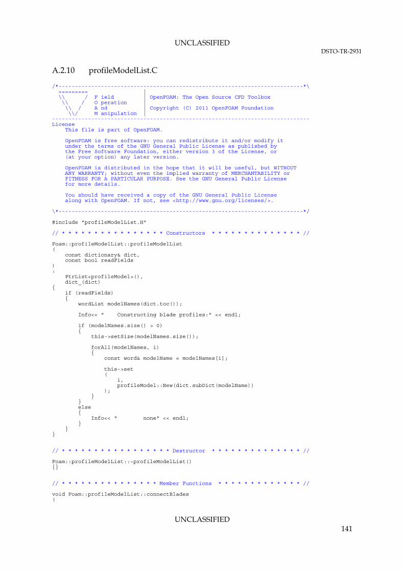
UNCLASSIFIED DSTO-TR-2931
UNCLASSIFIED 141
A.2.10 profileModelList.C
/*---------------------------------------------------------------------------*\ ========= | \\ / F ield | OpenFOAM: The Open Source CFD Toolbox \\ / O peration | \\ / A nd | Copyright (C) 2011 OpenFOAM Foundation \\/ M anipulation | ------------------------------------------------------------------------------- License This file is part of OpenFOAM. OpenFOAM is free software: you can redistribute it and/or modify it under the terms of the GNU General Public License as published by the Free Software Foundation, either version 3 of the License, or (at your option) any later version. OpenFOAM is distributed in the hope that it will be useful, but WITHOUT ANY WARRANTY; without even the implied warranty of MERCHANTABILITY or FITNESS FOR A PARTICULAR PURPOSE. See the GNU General Public License for more details. You should have received a copy of the GNU General Public License along with OpenFOAM. If not, see <http://www.gnu.org/licenses/>. \*---------------------------------------------------------------------------*/ #include "profileModelList.H" // * * * * * * * * * * * * * * * * Constructors * * * * * * * * * * * * * * // Foam::profileModelList::profileModelList ( const dictionary& dict, const bool readFields ) : PtrList<profileModel>(), dict_(dict) { if (readFields) { wordList modelNames(dict.toc()); Info<< " Constructing blade profiles:" << endl; if (modelNames.size() > 0) { this->setSize(modelNames.size()); forAll(modelNames, i) { const word& modelName = modelNames[i]; this->set ( i, profileModel::New(dict.subDict(modelName)) ); } } else { Info<< " none" << endl; } } } // * * * * * * * * * * * * * * * * * Destructor * * * * * * * * * * * * * * // Foam::profileModelList::~profileModelList() {} // * * * * * * * * * * * * * * * Member Functions * * * * * * * * * * * * * // void Foam::profileModelList::connectBlades (

UNCLASSIFIED DSTO-TR-2931
UNCLASSIFIED 142
const List<word>& names, List<label>& addr ) const { // construct the addressing between blade sections and profiles forAll(names, bI) { label index = -1; const word& profileName = names[bI]; forAll(*this, pI) { const profileModel& pm = this->operator[](pI); if (pm.name() == profileName) { index = pI; break; } } if (index == -1) { List<word> profileNames(size()); forAll(*this, i) { const profileModel& pm = this->operator[](i); profileNames[i] = pm.name(); } FatalErrorIn("void Foam::connectBlades(List<word>& names) const") << "Profile " << profileName << " could not be found " << "in profile list. Available profiles are" << profileNames << exit(FatalError); } else { addr[bI] = index; } } } // ************************************************************************* //

UNCLASSIFIED DSTO-TR-2931
UNCLASSIFIED 143
A.2.11 lookupProfile.H
/*---------------------------------------------------------------------------*\ ========= | \\ / F ield | OpenFOAM: The Open Source CFD Toolbox \\ / O peration | \\ / A nd | Copyright (C) 2011 OpenFOAM Foundation \\/ M anipulation | ------------------------------------------------------------------------------- License This file is part of OpenFOAM. OpenFOAM is free software: you can redistribute it and/or modify it under the terms of the GNU General Public License as published by the Free Software Foundation, either version 3 of the License, or (at your option) any later version. OpenFOAM is distributed in the hope that it will be useful, but WITHOUT ANY WARRANTY; without even the implied warranty of MERCHANTABILITY or FITNESS FOR A PARTICULAR PURPOSE. See the GNU General Public License for more details. You should have received a copy of the GNU General Public License along with OpenFOAM. If not, see <http://www.gnu.org/licenses/>. Class Foam::lookupProfile Description Look-up based profile data - drag and lift coefficients are lineraly interpolated based on the supplied angle of attack Input in list format: data ( (AOA1 Cd1 Cl2) (AOA2 Cd2 Cl2) ... (AOAN CdN CdN) ); where: AOA = angle of attack [deg] converted to [rad] internally Cd = drag coefficient Cl = lift coefficient SourceFiles lookupProfile.C \*---------------------------------------------------------------------------*/ #ifndef lookupProfile_H #define lookupProfile_H #include "profileModel.H" #include "List.H" // * * * * * * * * * * * * * * * * * * * * * * * * * * * * * * * * * * * * * // namespace Foam { /*---------------------------------------------------------------------------*\ Class lookupProfile Declaration \*---------------------------------------------------------------------------*/ class lookupProfile : public profileModel { protected: // Protected data //- List of angle-of-attack values [deg] on input, converted to [rad] List<scalar> AOA_;

UNCLASSIFIED DSTO-TR-2931
UNCLASSIFIED 144
//- List of drag coefficient values List<scalar> Cd_; //- List of lift coefficient values List<scalar> Cl_; // Protected Member Functions //- Return the interpolation indices and gradient void interpolateWeights ( const scalar& xIn, const List<scalar>& values, label& i1, label& i2, scalar& ddx ) const; public: //- Runtime type information TypeName("lookup"); //- Constructor lookupProfile(const dictionary& dict, const word& modelName); // Member functions // Evaluation //- Return the Cd and Cl for a given angle-of-attack virtual void Cdl(const scalar alpha, scalar& Cd, scalar& Cl) const; }; // * * * * * * * * * * * * * * * * * * * * * * * * * * * * * * * * * * * * * // } // End namespace Foam // * * * * * * * * * * * * * * * * * * * * * * * * * * * * * * * * * * * * * // #endif // ************************************************************************* //

UNCLASSIFIED DSTO-TR-2931
UNCLASSIFIED 145
A.2.12 lookupProfile.C
/*---------------------------------------------------------------------------*\ ========= | \\ / F ield | OpenFOAM: The Open Source CFD Toolbox \\ / O peration | \\ / A nd | Copyright (C) 2011-2012 OpenFOAM Foundation \\/ M anipulation | ------------------------------------------------------------------------------- License This file is part of OpenFOAM. OpenFOAM is free software: you can redistribute it and/or modify it under the terms of the GNU General Public License as published by the Free Software Foundation, either version 3 of the License, or (at your option) any later version. OpenFOAM is distributed in the hope that it will be useful, but WITHOUT ANY WARRANTY; without even the implied warranty of MERCHANTABILITY or FITNESS FOR A PARTICULAR PURPOSE. See the GNU General Public License for more details. You should have received a copy of the GNU General Public License along with OpenFOAM. If not, see <http://www.gnu.org/licenses/>. \*---------------------------------------------------------------------------*/ #include "lookupProfile.H" #include "addToRunTimeSelectionTable.H" #include "vector.H" #include "unitConversion.H" #include "IFstream.H" // * * * * * * * * * * * * * * * * * * * * * * * * * * * * * * * * * * * * * // namespace Foam { defineTypeNameAndDebug(lookupProfile, 0); addToRunTimeSelectionTable(profileModel, lookupProfile, dictionary); } // * * * * * * * * * * * * Protected Member Functions * * * * * * * * * * * // void Foam::lookupProfile::interpolateWeights ( const scalar& xIn, const List<scalar>& values, label& i1, label& i2, scalar& ddx ) const { i2 = 0; label nElem = values.size(); if (nElem == 1) { i1 = i2; ddx = 0.0; return; } else { while ((values[i2] < xIn) && (i2 < nElem)) { i2++; } if (i2 == nElem) { i2 = nElem - 1; i1 = i2; ddx = 0.0; return; } else { i1 = i2 - 1;

UNCLASSIFIED DSTO-TR-2931
UNCLASSIFIED 146
ddx = (xIn - values[i1])/(values[i2] - values[i1]); } } } // * * * * * * * * * * * * * * * * Constructors * * * * * * * * * * * * * * // Foam::lookupProfile::lookupProfile ( const dictionary& dict, const word& modelName ) : profileModel(dict, modelName), AOA_(), Cd_(), Cl_() { List<vector> data; if (readFromFile()) { IFstream is(fName_); is >> data; } else { dict.lookup("data") >> data; } if (data.size() > 0) { AOA_.setSize(data.size()); Cd_.setSize(data.size()); Cl_.setSize(data.size()); forAll(data, i) { AOA_[i] = degToRad(data[i][0]); Cd_[i] = data[i][1]; Cl_[i] = data[i][2]; } } else { FatalErrorIn ( "Foam::lookupProfile::lookupProfile" "(" "const dictionary&, " "const word&" ")" ) << "No profile data specified" << exit(FatalError); } } // * * * * * * * * * * * * * * * Member Functions * * * * * * * * * * * * * // void Foam::lookupProfile::Cdl(const scalar alpha, scalar& Cd, scalar& Cl) const { label i1 = -1; label i2 = -1; scalar invAlpha = -1.0; interpolateWeights(alpha, AOA_, i1, i2, invAlpha); Cd = invAlpha*(Cd_[i2] - Cd_[i1]) + Cd_[i1]; Cl = invAlpha*(Cl_[i2] - Cl_[i1]) + Cl_[i1]; } // ************************************************************************* //

UNCLASSIFIED DSTO-TR-2931
UNCLASSIFIED 147
A.2.13 seriesProfile.H
/*---------------------------------------------------------------------------*\ ========= | \\ / F ield | OpenFOAM: The Open Source CFD Toolbox \\ / O peration | \\ / A nd | Copyright (C) 2011-2012 OpenFOAM Foundation \\/ M anipulation | ------------------------------------------------------------------------------- License This file is part of OpenFOAM. OpenFOAM is free software: you can redistribute it and/or modify it under the terms of the GNU General Public License as published by the Free Software Foundation, either version 3 of the License, or (at your option) any later version. OpenFOAM is distributed in the hope that it will be useful, but WITHOUT ANY WARRANTY; without even the implied warranty of MERCHANTABILITY or FITNESS FOR A PARTICULAR PURPOSE. See the GNU General Public License for more details. You should have received a copy of the GNU General Public License along with OpenFOAM. If not, see <http://www.gnu.org/licenses/>. Class Foam::seriesProfile Description Series-up based profile data - drag and lift coefficients computed as sum of cosine series Cd = sum_i(CdCoeff)*cos(i*AOA) Cl = sum_i(ClCoeff)*sin(i*AOA) where: AOA = angle of attack [deg] converted to [rad] internally Cd = drag coefficent Cl = lift coefficent Input in two (arbitrary length) lists: CdCoeffs (coeff1 coeff2 ... coeffN); ClCoeffs (coeff1 coeff2 ... coeffN); SourceFiles seriesProfile.C \*---------------------------------------------------------------------------*/ #ifndef seriesProfile_H #define seriesProfile_H #include "profileModel.H" #include "List.H" // * * * * * * * * * * * * * * * * * * * * * * * * * * * * * * * * * * * * * // namespace Foam { /*---------------------------------------------------------------------------*\ Class seriesProfile Declaration \*---------------------------------------------------------------------------*/ class seriesProfile : public profileModel { protected: // Protected data //- List of drag coefficient values List<scalar> CdCoeffs_; //- List of lift coefficient values List<scalar> ClCoeffs_;

UNCLASSIFIED DSTO-TR-2931
UNCLASSIFIED 148
// Protected Member Functions // Evaluate //- Drag scalar evaluateDrag ( const scalar& xIn, const List<scalar>& values ) const; //- Lift scalar evaluateLift ( const scalar& xIn, const List<scalar>& values ) const; public: //- Runtime type information TypeName("series"); //- Constructor seriesProfile(const dictionary& dict, const word& modelName); // Member functions // Evaluation //- Return the Cd and Cl for a given angle-of-attack virtual void Cdl(const scalar alpha, scalar& Cd, scalar& Cl) const; }; // * * * * * * * * * * * * * * * * * * * * * * * * * * * * * * * * * * * * * // } // End namespace Foam // * * * * * * * * * * * * * * * * * * * * * * * * * * * * * * * * * * * * * // #endif // ************************************************************************* //

UNCLASSIFIED DSTO-TR-2931
UNCLASSIFIED 149
A.2.14 seriesProfile.C
/*---------------------------------------------------------------------------*\ ========= | \\ / F ield | OpenFOAM: The Open Source CFD Toolbox \\ / O peration | \\ / A nd | Copyright (C) 2011-2012 OpenFOAM Foundation \\/ M anipulation | ------------------------------------------------------------------------------- License This file is part of OpenFOAM. OpenFOAM is free software: you can redistribute it and/or modify it under the terms of the GNU General Public License as published by the Free Software Foundation, either version 3 of the License, or (at your option) any later version. OpenFOAM is distributed in the hope that it will be useful, but WITHOUT ANY WARRANTY; without even the implied warranty of MERCHANTABILITY or FITNESS FOR A PARTICULAR PURPOSE. See the GNU General Public License for more details. You should have received a copy of the GNU General Public License along with OpenFOAM. If not, see <http://www.gnu.org/licenses/>. \*---------------------------------------------------------------------------*/ #include "seriesProfile.H" #include "addToRunTimeSelectionTable.H" #include "IFstream.H" // * * * * * * * * * * * * * * * * * * * * * * * * * * * * * * * * * * * * * // namespace Foam { defineTypeNameAndDebug(seriesProfile, 0); addToRunTimeSelectionTable(profileModel, seriesProfile, dictionary); } // * * * * * * * * * * * * Protected Member Functions * * * * * * * * * * * // Foam::scalar Foam::seriesProfile::evaluateDrag ( const scalar& xIn, const List<scalar>& values ) const { scalar result = 0.0; forAll(values, i) { result += values[i]*cos(i*xIn); } return result; } Foam::scalar Foam::seriesProfile::evaluateLift ( const scalar& xIn, const List<scalar>& values ) const { scalar result = 0.0; forAll(values, i) { result += values[i]*sin(i*xIn); } return result; } // * * * * * * * * * * * * * * * * Constructors * * * * * * * * * * * * * * // Foam::seriesProfile::seriesProfile

UNCLASSIFIED DSTO-TR-2931
UNCLASSIFIED 150
( const dictionary& dict, const word& modelName ) : profileModel(dict, modelName), CdCoeffs_(), ClCoeffs_() { if (readFromFile()) { IFstream is(fName_); is >> CdCoeffs_ >> ClCoeffs_; } else { dict.lookup("CdCoeffs") >> CdCoeffs_; dict.lookup("ClCoeffs") >> ClCoeffs_; } if (CdCoeffs_.empty()) { FatalErrorIn ( "Foam::seriesProfile::seriesProfile" "(" "const dictionary&, " "const word&" ")" ) << "CdCoeffs must be specified" << exit(FatalError); } if (ClCoeffs_.empty()) { FatalErrorIn ( "Foam::seriesProfile::seriesProfile" "(" "const dictionary&, " "const word&" ")" ) << "ClCoeffs must be specified" << exit(FatalError); } } // * * * * * * * * * * * * * * * Member Functions * * * * * * * * * * * * * // void Foam::seriesProfile::Cdl(const scalar alpha, scalar& Cd, scalar& Cl) const { Cd = evaluateDrag(alpha, CdCoeffs_); Cl = evaluateLift(alpha, ClCoeffs_); } // ************************************************************************* //

UNCLASSIFIED DSTO-TR-2931
UNCLASSIFIED 151
A.2.15 trimModel.H
/*---------------------------------------------------------------------------*\ ========= | \\ / F ield | OpenFOAM: The Open Source CFD Toolbox \\ / O peration | \\ / A nd | Copyright (C) 2012 OpenFOAM Foundation \\/ M anipulation | ------------------------------------------------------------------------------- License This file is part of OpenFOAM. OpenFOAM is free software: you can redistribute it and/or modify it under the terms of the GNU General Public License as published by the Free Software Foundation, either version 3 of the License, or (at your option) any later version. OpenFOAM is distributed in the hope that it will be useful, but WITHOUT ANY WARRANTY; without even the implied warranty of MERCHANTABILITY or FITNESS FOR A PARTICULAR PURPOSE. See the GNU General Public License for more details. You should have received a copy of the GNU General Public License along with OpenFOAM. If not, see <http://www.gnu.org/licenses/>. Class Foam::trimModel Description Trim model abstract class SourceFiles trimModel.C \*---------------------------------------------------------------------------*/ #ifndef trimModel_H #define trimModel_H #include "rotorDiskSource.H" #include "dictionary.H" #include "runTimeSelectionTables.H" // * * * * * * * * * * * * * * * * * * * * * * * * * * * * * * * * * * * * * // namespace Foam { /*---------------------------------------------------------------------------*\ Class trimModel Declaration \*---------------------------------------------------------------------------*/ class trimModel { protected: // Protected data //- Reference to the rotor source model const rotorDiskSource& rotor_; //- Name of model const word name_; //- Coefficients dictionary dictionary coeffs_; public: //- Run-time type information TypeName("trimModel"); // Declare runtime constructor selection table declareRunTimeSelectionTable (

UNCLASSIFIED DSTO-TR-2931
UNCLASSIFIED 152
autoPtr, trimModel, dictionary, ( const rotorDiskSource& rotor, const dictionary& dict ), (rotor, dict) ); // Constructors //- Construct from components trimModel ( const rotorDiskSource& rotor, const dictionary& dict, const word& name ); // Selectors //- Return a pointer to the selected trim model static autoPtr<trimModel> New ( const rotorDiskSource& rotor, const dictionary& dict ); //- Destructor virtual ~trimModel(); // Member functions //- Read virtual void read(const dictionary& dict); //- Return the geometric angle of attack [rad] virtual tmp<scalarField> alphag() const = 0; //- Correct the model virtual void correct(const vectorField& U, vectorField& force) = 0; }; // * * * * * * * * * * * * * * * * * * * * * * * * * * * * * * * * * * * * * // } // End namespace Foam // * * * * * * * * * * * * * * * * * * * * * * * * * * * * * * * * * * * * * // #endif // ************************************************************************* //

UNCLASSIFIED DSTO-TR-2931
UNCLASSIFIED 153
A.2.16 trimModel.C
/*---------------------------------------------------------------------------*\ ========= | \\ / F ield | OpenFOAM: The Open Source CFD Toolbox \\ / O peration | \\ / A nd | Copyright (C) 2012 OpenFOAM Foundation \\/ M anipulation | ------------------------------------------------------------------------------- License This file is part of OpenFOAM. OpenFOAM is free software: you can redistribute it and/or modify it under the terms of the GNU General Public License as published by the Free Software Foundation, either version 3 of the License, or (at your option) any later version. OpenFOAM is distributed in the hope that it will be useful, but WITHOUT ANY WARRANTY; without even the implied warranty of MERCHANTABILITY or FITNESS FOR A PARTICULAR PURPOSE. See the GNU General Public License for more details. You should have received a copy of the GNU General Public License along with OpenFOAM. If not, see <http://www.gnu.org/licenses/>. \*---------------------------------------------------------------------------*/ #include "trimModel.H" // * * * * * * * * * * * * * * Static Data Members * * * * * * * * * * * * * // namespace Foam { defineTypeNameAndDebug(trimModel, 0); defineRunTimeSelectionTable(trimModel, dictionary); } // * * * * * * * * * * * * * * * * Constructors * * * * * * * * * * * * * * // Foam::trimModel::trimModel ( const rotorDiskSource& rotor, const dictionary& dict, const word& name ) : rotor_(rotor), name_(name), coeffs_(dictionary::null) { read(dict); } // * * * * * * * * * * * * * * * * * Destructor * * * * * * * * * * * * * * // Foam::trimModel::~trimModel() {} // * * * * * * * * * * * * * * * Member Functions * * * * * * * * * * * * * // void Foam::trimModel::read(const dictionary& dict) { coeffs_ = dict.subDict(name_ + "Coeffs"); } // ************************************************************************* //
UNCLASSIFIED DSTO-TR-2931
UNCLASSIFIED 154
A.2.17 trimModelNew.C
/*---------------------------------------------------------------------------*\ ========= | \\ / F ield | OpenFOAM: The Open Source CFD Toolbox \\ / O peration | \\ / A nd | Copyright (C) 2012 OpenFOAM Foundation \\/ M anipulation | ------------------------------------------------------------------------------- License This file is part of OpenFOAM. OpenFOAM is free software: you can redistribute it and/or modify it under the terms of the GNU General Public License as published by the Free Software Foundation, either version 3 of the License, or (at your option) any later version. OpenFOAM is distributed in the hope that it will be useful, but WITHOUT ANY WARRANTY; without even the implied warranty of MERCHANTABILITY or FITNESS FOR A PARTICULAR PURPOSE. See the GNU General Public License for more details. You should have received a copy of the GNU General Public License along with OpenFOAM. If not, see <http://www.gnu.org/licenses/>. \*---------------------------------------------------------------------------*/ #include "trimModel.H" // * * * * * * * * * * * * * * * * Constructors * * * * * * * * * * * * * * // Foam::autoPtr<Foam::trimModel> Foam::trimModel::New ( const rotorDiskSource& rotor, const dictionary& dict ) { const word modelType(dict.lookup(typeName)); Info<< " Selecting " << typeName << " " << modelType << endl; dictionaryConstructorTable::iterator cstrIter = dictionaryConstructorTablePtr_->find(modelType); if (cstrIter == dictionaryConstructorTablePtr_->end()) { FatalErrorIn ( "trimModel::New(const rotorDiskSource&, const dictionary&)" ) << "Unknown " << typeName << " type " << modelType << nl << nl << "Valid " << typeName << " types are:" << nl << dictionaryConstructorTablePtr_->sortedToc() << exit(FatalError); } return autoPtr<trimModel>(cstrIter()(rotor, dict)); } // ************************************************************************* //

UNCLASSIFIED DSTO-TR-2931
UNCLASSIFIED 155
A.2.18 fixedTrim.H
/*---------------------------------------------------------------------------*\ ========= | \\ / F ield | OpenFOAM: The Open Source CFD Toolbox \\ / O peration | \\ / A nd | Copyright (C) 2012 OpenFOAM Foundation \\/ M anipulation | ------------------------------------------------------------------------------- License This file is part of OpenFOAM. OpenFOAM is free software: you can redistribute it and/or modify it under the terms of the GNU General Public License as published by the Free Software Foundation, either version 3 of the License, or (at your option) any later version. OpenFOAM is distributed in the hope that it will be useful, but WITHOUT ANY WARRANTY; without even the implied warranty of MERCHANTABILITY or FITNESS FOR A PARTICULAR PURPOSE. See the GNU General Public License for more details. You should have received a copy of the GNU General Public License along with OpenFOAM. If not, see <http://www.gnu.org/licenses/>. Class Foam::fixedTrim Description Fixed trim coefficients SourceFiles fixedTrim.C \*---------------------------------------------------------------------------*/ #ifndef fixedTrim_H #define fixedTrim_H #include "trimModel.H" // * * * * * * * * * * * * * * * * * * * * * * * * * * * * * * * * * * * * * // namespace Foam { /*---------------------------------------------------------------------------*\ Class fixedTrim Declaration \*---------------------------------------------------------------------------*/ class fixedTrim : public trimModel { protected: // Protected data //- Geometric angle of attack [rad] scalarField alphag_; public: //- Run-time type information TypeName("fixedTrim"); //- Constructor fixedTrim(const rotorDiskSource& rotor, const dictionary& dict); //- Destructor virtual ~fixedTrim(); // Member functions //- Read void read(const dictionary& dict);

UNCLASSIFIED DSTO-TR-2931
UNCLASSIFIED 156
//- Return the geometric angle of attack [rad] virtual tmp<scalarField> alphag() const; //- Correct the model virtual void correct(const vectorField& U, vectorField& force); }; // * * * * * * * * * * * * * * * * * * * * * * * * * * * * * * * * * * * * * // } // End namespace Foam // * * * * * * * * * * * * * * * * * * * * * * * * * * * * * * * * * * * * * // #endif // ************************************************************************* //

UNCLASSIFIED DSTO-TR-2931
UNCLASSIFIED 157
A.2.19 fixedTrim.C
/*---------------------------------------------------------------------------*\ ========= | \\ / F ield | OpenFOAM: The Open Source CFD Toolbox \\ / O peration | \\ / A nd | Copyright (C) 2012 OpenFOAM Foundation \\/ M anipulation | ------------------------------------------------------------------------------- License This file is part of OpenFOAM. OpenFOAM is free software: you can redistribute it and/or modify it under the terms of the GNU General Public License as published by the Free Software Foundation, either version 3 of the License, or (at your option) any later version. OpenFOAM is distributed in the hope that it will be useful, but WITHOUT ANY WARRANTY; without even the implied warranty of MERCHANTABILITY or FITNESS FOR A PARTICULAR PURPOSE. See the GNU General Public License for more details. You should have received a copy of the GNU General Public License along with OpenFOAM. If not, see <http://www.gnu.org/licenses/>. \*---------------------------------------------------------------------------*/ #include "fixedTrim.H" #include "addToRunTimeSelectionTable.H" #include "unitConversion.H" #include "mathematicalConstants.H" using namespace Foam::constant; // * * * * * * * * * * * * * * Static Data Members * * * * * * * * * * * * * // namespace Foam { defineTypeNameAndDebug(fixedTrim, 0); addToRunTimeSelectionTable(trimModel, fixedTrim, dictionary); } // * * * * * * * * * * * * * * * * Constructors * * * * * * * * * * * * * * // Foam::fixedTrim::fixedTrim(const rotorDiskSource& rotor, const dictionary& dict) : trimModel(rotor, dict, typeName), alphag_(rotor.cells().size(), 0.0) { read(dict); } // * * * * * * * * * * * * * * * * * Destructor * * * * * * * * * * * * * * // Foam::fixedTrim::~fixedTrim() {} // * * * * * * * * * * * * * * * Member Functions * * * * * * * * * * * * * // void Foam::fixedTrim::read(const dictionary& dict) { trimModel::read(dict); scalar alphaC = degToRad(readScalar(coeffs_.lookup("alphaC"))); scalar A = degToRad(readScalar(coeffs_.lookup("A"))); scalar B = degToRad(readScalar(coeffs_.lookup("B"))); const List<vector>& x = rotor_.x(); forAll(alphag_, i) { scalar psi = x[i].y(); alphag_[i] = alphaC + A*cos(psi) + B*sin(psi); } }

UNCLASSIFIED DSTO-TR-2931
UNCLASSIFIED 158
Foam::tmp<Foam::scalarField> Foam::fixedTrim::alphag() const { return tmp<scalarField>(alphag_); } void Foam::fixedTrim::correct(const vectorField& U, vectorField& force) { // do nothing - untrimmed model } // ************************************************************************* //
UNCLASSIFIED DSTO-TR-2931
UNCLASSIFIED 159
A.2.20 targetForceTrim.H
/*---------------------------------------------------------------------------*\ ========= | \\ / F ield | OpenFOAM: The Open Source CFD Toolbox \\ / O peration | \\ / A nd | Copyright (C) 2012 OpenFOAM Foundation \\/ M anipulation | ------------------------------------------------------------------------------- License This file is part of OpenFOAM. OpenFOAM is free software: you can redistribute it and/or modify it under the terms of the GNU General Public License as published by the Free Software Foundation, either version 3 of the License, or (at your option) any later version. OpenFOAM is distributed in the hope that it will be useful, but WITHOUT ANY WARRANTY; without even the implied warranty of MERCHANTABILITY or FITNESS FOR A PARTICULAR PURPOSE. See the GNU General Public License for more details. You should have received a copy of the GNU General Public License along with OpenFOAM. If not, see <http://www.gnu.org/licenses/>. Class Foam::targetForceTrim Description Target force trim coefficients SourceFiles targetForceTrim.C \*---------------------------------------------------------------------------*/ #ifndef targetForceTrim_H #define targetForceTrim_H #include "trimModel.H" #include "tensor.H" #include "vector.H" // * * * * * * * * * * * * * * * * * * * * * * * * * * * * * * * * * * * * * // namespace Foam { /*---------------------------------------------------------------------------*\ Class targetForceTrim Declaration \*---------------------------------------------------------------------------*/ class targetForceTrim : public trimModel { protected: // Protected data //- Number of iterations between calls to 'correct' label calcFrequency_; //- Target force [N] vector target_; //- Pitch angles (collective, roll, pitch) [rad] vector alpha_; //- Maximum number of iterations in trim routine label nIter_; //- Convergence tolerance scalar tol_; //- Under-relaxation coefficient scalar relax_;
UNCLASSIFIED DSTO-TR-2931
UNCLASSIFIED 160
//- Perturbation angle used to determine jacobian scalar dTheta_; // Protected member functions //- Calculate the rotor forces vector calcForce ( const vectorField& U, const scalarField& alphag, vectorField& force ) const; public: //- Run-time type information TypeName("targetForceTrim"); //- Constructor targetForceTrim(const rotorDiskSource& rotor, const dictionary& dict); //- Destructor virtual ~targetForceTrim(); // Member functions //- Read void read(const dictionary& dict); //- Return the geometric angle of attack [rad] virtual tmp<scalarField> alphag() const; //- Correct the model virtual void correct(const vectorField& U, vectorField& force); }; // * * * * * * * * * * * * * * * * * * * * * * * * * * * * * * * * * * * * * // } // End namespace Foam // * * * * * * * * * * * * * * * * * * * * * * * * * * * * * * * * * * * * * // #endif // ************************************************************************* //

UNCLASSIFIED DSTO-TR-2931
UNCLASSIFIED 161
A.2.21 targetForceTrim.C
/*---------------------------------------------------------------------------*\ ========= | \\ / F ield | OpenFOAM: The Open Source CFD Toolbox \\ / O peration | \\ / A nd | Copyright (C) 2012 OpenFOAM Foundation \\/ M anipulation | ------------------------------------------------------------------------------- License This file is part of OpenFOAM. OpenFOAM is free software: you can redistribute it and/or modify it under the terms of the GNU General Public License as published by the Free Software Foundation, either version 3 of the License, or (at your option) any later version. OpenFOAM is distributed in the hope that it will be useful, but WITHOUT ANY WARRANTY; without even the implied warranty of MERCHANTABILITY or FITNESS FOR A PARTICULAR PURPOSE. See the GNU General Public License for more details. You should have received a copy of the GNU General Public License along with OpenFOAM. If not, see <http://www.gnu.org/licenses/>. \*---------------------------------------------------------------------------*/ #include "targetForceTrim.H" #include "addToRunTimeSelectionTable.H" #include "unitConversion.H" #include "mathematicalConstants.H" using namespace Foam::constant; // * * * * * * * * * * * * * * Static Data Members * * * * * * * * * * * * * // namespace Foam { defineTypeNameAndDebug(targetForceTrim, 0); addToRunTimeSelectionTable(trimModel, targetForceTrim, dictionary); } // * * * * * * * * * * * * Protected Member Functions * * * * * * * * * * * // Foam::vector Foam::targetForceTrim::calcForce ( const vectorField& U, const scalarField& alphag, vectorField& force ) const { rotor_.calculate(U, alphag, force, false); const labelList& cells = rotor_.cells(); const vectorField& C = rotor_.mesh().C(); const vector& origin = rotor_.coordSys().origin(); const vector& rollAxis = rotor_.coordSys().e1(); const vector& pitchAxis = rotor_.coordSys().e2(); const vector& yawAxis = rotor_.coordSys().e3(); vector f(vector::zero); forAll(cells, i) { label cellI = cells[i]; vector moment = force[cellI]^(C[cellI] - origin); //cross product f[0] += force[cellI] & yawAxis; //dot product f[1] += moment & pitchAxis; f[2] += moment & rollAxis; } reduce(f, sumOp<vector>()); return f; }

UNCLASSIFIED DSTO-TR-2931
UNCLASSIFIED 162
// * * * * * * * * * * * * * * * * Constructors * * * * * * * * * * * * * * // Foam::targetForceTrim::targetForceTrim ( const rotorDiskSource& rotor, const dictionary& dict ) : trimModel(rotor, dict, typeName), calcFrequency_(-1), target_(vector::zero), alpha_(vector::zero), nIter_(50), tol_(1e-8), relax_(1.0), dTheta_(degToRad(0.05)) { read(dict); } // * * * * * * * * * * * * * * * * * Destructor * * * * * * * * * * * * * * // Foam::targetForceTrim::~targetForceTrim() {} // * * * * * * * * * * * * * * * Member Functions * * * * * * * * * * * * * // void Foam::targetForceTrim::read ( const dictionary& dict ) { trimModel::read(dict); const dictionary& targetDict(coeffs_.subDict("target")); const bool IsCompressible = rotor_.getRhoName() != "none"; if (IsCompressible != 0) { target_[0] = readScalar(targetDict.lookup("fThrust")); target_[1] = readScalar(targetDict.lookup("mPitch")); target_[2] = readScalar(targetDict.lookup("mRoll")); } if (IsCompressible == 0) { target_[0] = (readScalar(targetDict.lookup("fThrust")))/(rotor_.getRhoRef()); target_[1] = (readScalar(targetDict.lookup("mPitch")))/(rotor_.getRhoRef()); target_[2] = (readScalar(targetDict.lookup("mRoll")))/(rotor_.getRhoRef()); } const dictionary& pitchAngleDict(coeffs_.subDict("pitchAngles")); alpha_[0] = degToRad(readScalar(pitchAngleDict.lookup("alphaCIni"))); alpha_[1] = degToRad(readScalar(pitchAngleDict.lookup("AIni"))); alpha_[2] = degToRad(readScalar(pitchAngleDict.lookup("BIni"))); coeffs_.lookup("calcFrequency") >> calcFrequency_; coeffs_.readIfPresent("nIter", nIter_); coeffs_.readIfPresent("tol", tol_); coeffs_.readIfPresent("relax", relax_); if (coeffs_.readIfPresent("dTheta", dTheta_)) { dTheta_ = degToRad(dTheta_); } } Foam::tmp<Foam::scalarField> Foam::targetForceTrim::alphag() const { const List<vector>& x = rotor_.x(); tmp<scalarField> ta(new scalarField(x.size())); scalarField& a = ta(); forAll(a, i)

UNCLASSIFIED DSTO-TR-2931
UNCLASSIFIED 163
{ scalar psi = x[i].y(); a[i] = alpha_[0] + alpha_[1]*cos(psi) + alpha_[2]*sin(psi); } return ta; } void Foam::targetForceTrim::correct(const vectorField& U, vectorField& force) { if (rotor_.mesh().time().timeIndex() % calcFrequency_ == 0) { // iterate to find new pitch angles to achieve target force scalar err = GREAT; label iter = 0; tensor J(tensor::zero); while ((err > tol_) && (iter < nIter_)) { // cache initial alpha vector vector alpha0(alpha_); // set initial values // gets re-initialised everytime this function is called vector old = calcForce(U, alphag(), force); // construct Jacobian by perturbing the pitch angles // by +/-(dTheta_/2) for (label pitchI = 0; pitchI < 3; pitchI++) { alpha_[pitchI] -= dTheta_/2.0; vector f0 = calcForce(U, alphag(), force); alpha_[pitchI] += dTheta_; vector f1 = calcForce(U, alphag(), force); vector ddTheta = (f1 - f0)/dTheta_; J[pitchI + 0] = ddTheta[0]; J[pitchI + 3] = ddTheta[1]; J[pitchI + 6] = ddTheta[2]; alpha_ = alpha0; } // calculate the change in pitch angle vector vector dAlpha = inv(J) & (target_ - old); // update pitch angles vector alphaNew = alpha_ + relax_*dAlpha; // update error err = mag(alphaNew - alpha_); // update for next iteration alpha_ = alphaNew; // next iteration iter++; } const bool IsCompressible = rotor_.getRhoName() != "none"; if (iter == nIter_) { WarningIn ( "void Foam::targetForceTrim::correct" "(" "const vectorField&, " "vectorField&" ")" ) << " Trim routine not converged in " << iter << " iterations, max residual = " << err << endl; } else { if (IsCompressible) {

UNCLASSIFIED DSTO-TR-2931
UNCLASSIFIED 164
Info<< type() << ": Target Force and Moments " << nl << " Target Thrust = " << target_.x() << nl << " Target Pitching Moment = " << target_.y() << nl << " Target Rolling Moment = " << target_.z() << nl << " isCompressible = " << IsCompressible << endl; } if (!IsCompressible) { Info<< type() << ": Target Force and Moments " << nl << " Target Thrust = " << (target_.x()*rotor_.getRhoRef()) << nl << " Target Pitching Moment = " << (target_.y()*rotor_.getRhoRef()) << nl << " Target Rolling Moment = " << (target_.z()*rotor_.getRhoRef()) << nl << " isCompressible = " << IsCompressible << endl; } Info<< type() << ": converged in " << iter << " iterations" << nl << " residual = " << err << endl; } Info<< " new pitch angles:" << nl << " alphaC = " << radToDeg(alpha_[0]) << nl << " A = " << radToDeg(alpha_[1]) << nl << " B = " << radToDeg(alpha_[2]) << nl << endl; } } // ************************************************************************* //

UNCLASSIFIED DSTO-TR-2931
UNCLASSIFIED 165
A.2.22 Make/files
rotorDiskSource.C bladeModel/bladeModel.C profileModel/profileModel.C profileModel/profileModelList.C profileModel/lookup/lookupProfile.C profileModel/series/seriesProfile.C trimModel/trimModel/trimModel.C trimModel/trimModel/trimModelNew.C trimModel/fixed/fixedTrim.C trimModel/targetForce/targetForceTrim.C LIB=$(FOAM_USER_LIBBIN)/librotorDiskSource A.2.23 Make/options
EXE_INC = \ -DFULL_DEBUG -g -O0 \ -I$(LIB_SRC)/meshTools/lnInclude \ -I$(LIB_SRC)/finiteVolume/lnInclude LIB_LIBS = \ -lmeshTools \ -lfiniteVolume

UNCLASSIFIED DSTO-TR-2931
UNCLASSIFIED 166
Appendix B A Sample Case Set Up using the Georgia Tech Validation Case for Running
rhoSimpleSourceFoam Solver with rotorDiskSource Active
B.1. Overview
This appendix provides a copy of the OpenFOAM case files used for running the Georgia Tech Rotor-Airframe Validation Case using OpenFOAM 2.1.x. The purpose of this appendix is to provide user with an example of a typical case setup needed for running a steady compressible (pressure-based) solver, rhoSimpleSourceFoam, using the rotorDiskSource library. The mesh files have been omitted from this Appendix. However, to aid in providing a context for the boundary conditions set up, the “constant/polyMesh/boundary” file have been included. The “boundary” file provides the list of the names of the domain boundary patches included in the mesh. The current setup assumes that there is one rotor disk cellZone included in the mesh, named rotorcell. The targetForce trim is used with the same trim parameters as those specified in Section 5.4.3. Table B.1 presents a sorted list of the case configuration files shown in Section B.2. To improve readability, comments in the code have been shown in blue. Table B.1: Summary of a sample rhoSimpleSourceFoam case configuration files
Section path/filename (path is assumed to be relative to the case PWD)
Description
constant/polyMesh/boundary Contains patch names and addressing. This file is part of the mesh files, which is automatically generated during mesh conversion process, or by using blockMesh
constant/RASProperties Contains RANS turbulence model selection constant/thermophysicalProperties Contains the fluid thermophysical properties, such as
molecular viscosity and Prandtl number constant/transportProperties Contains the fluid transport model selection, such as
Newtonian or Bird-Carreau, etc… constant/sourcesProperties Contains selections and definitions of field sources,
such as the rotorDiskSource Multiple sources (even of varying types) must be defined in this file.
0/p Boundary condition for pressure 0/U Boundary condition for velocity 0/T Boundary condition for temperature 0/k Boundary condition for turbulent kinetic energy 0/epsilon Boundary condition for turbulent dissipation rate
Table continues over page …
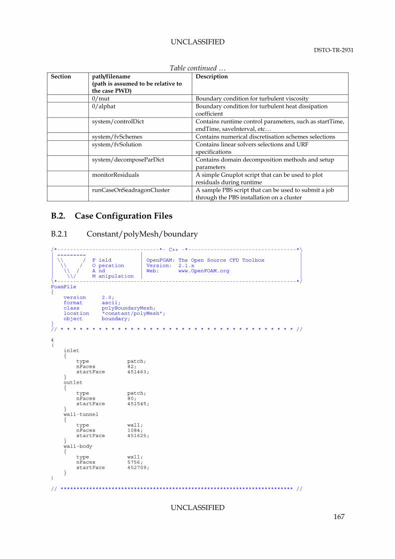
UNCLASSIFIED DSTO-TR-2931
UNCLASSIFIED 167
Table continued … Section path/filename
(path is assumed to be relative to the case PWD)
Description
0/mut Boundary condition for turbulent viscosity 0/alphat Boundary condition for turbulent heat dissipation
coefficient system/controlDict Contains runtime control parameters, such as startTime,
endTime, saveInterval, etc… system/fvSchemes Contains numerical discretisation schemes selections system/fvSolution Contains linear solvers selections and URF
specifications system/decomposeParDict Contains domain decomposition methods and setup
parameters monitorResiduals A simple Gnuplot script that can be used to plot
residuals during runtime runCaseOnSeadragonCluster A sample PBS script that can be used to submit a job
through the PBS installation on a cluster
B.2. Case Configuration Files
B.2.1 Constant/polyMesh/boundary
/*--------------------------------*- C++ -*----------------------------------*\ | ========= | | | \\ / F ield | OpenFOAM: The Open Source CFD Toolbox | | \\ / O peration | Version: 2.1.x | | \\ / A nd | Web: www.OpenFOAM.org | | \\/ M anipulation | | \*---------------------------------------------------------------------------*/ FoamFile { version 2.0; format ascii; class polyBoundaryMesh; location "constant/polyMesh"; object boundary; } // * * * * * * * * * * * * * * * * * * * * * * * * * * * * * * * * * * * * * // 4 ( inlet { type patch; nFaces 82; startFace 451463; } outlet { type patch; nFaces 80; startFace 451545; } wall-tunnel { type wall; nFaces 1084; startFace 451625; } wall-body { type wall; nFaces 5756; startFace 452709; } ) // ************************************************************************* //

UNCLASSIFIED DSTO-TR-2931
UNCLASSIFIED 168
B.2.2 constant/RASProperties
/*--------------------------------*- C++ -*----------------------------------*\ | ========= | | | \\ / F ield | OpenFOAM: The Open Source CFD Toolbox | | \\ / O peration | Version: dev | | \\ / A nd | Web: www.OpenFOAM.org | | \\/ M anipulation | | \*---------------------------------------------------------------------------*/ FoamFile { version 2.0; format ascii; class dictionary; object RASProperties; } // * * * * * * * * * * * * * * * * * * * * * * * * * * * * * * * * * * * * * // RASModel kEpsilon; //realizableKE; turbulence on; printCoeffs on; kEpsilonCoeffs { Cmu 0.09; C1 1.44; C2 1.92; C3 -0.33; sigmak 1.0; sigmaEps 1.11; //Original value is 1.44 Prt 1.0; } // ************************************************************************* //

UNCLASSIFIED DSTO-TR-2931
UNCLASSIFIED 169
B.2.3 constant/thermophysicalProperties
/*--------------------------------*- C++ -*----------------------------------*\ | ========= | | | \\ / F ield | OpenFOAM: The Open Source CFD Toolbox | | \\ / O peration | Version: 2.0.0 | | \\ / A nd | Web: www.OpenFOAM.org | | \\/ M anipulation | | \*---------------------------------------------------------------------------*/ FoamFile { version 2.0; format ascii; class dictionary; location "constant"; object thermophysicalProperties; } // * * * * * * * * * * * * * * * * * * * * * * * * * * * * * * * * * * * * * // thermoType hPsiThermo<pureMixture<constTransport<specieThermo<hConstThermo<perfectGas>>>>>; mixture { specie { nMoles 1; molWeight 28.966; } thermodynamics { Cp 1006.43; Hf 0.0; //not used – no heat release } transport { mu 17.894e-06; Pr 0.7; } } // ************************************************************************* //

UNCLASSIFIED DSTO-TR-2931
UNCLASSIFIED 170
B.2.4 constant/transportProperties
/*--------------------------------*- C++ -*----------------------------------*\ | ========= | | | \\ / F ield | OpenFOAM: The Open Source CFD Toolbox | | \\ / O peration | Version: dev | | \\ / A nd | Web: www.OpenFOAM.org | | \\/ M anipulation | | \*---------------------------------------------------------------------------*/ FoamFile { version 2.0; format ascii; class dictionary; object transportProperties; } // * * * * * * * * * * * * * * * * * * * * * * * * * * * * * * * * * * * * * // transportModel Newtonian; nu nu [0 2 -1 0 0 0 0] 1.5e-05; // ************************************************************************* //

UNCLASSIFIED DSTO-TR-2931
UNCLASSIFIED 171
B.2.5 constant/sourcesProperties
/*--------------------------------*- C++ -*----------------------------------*\ | ========= | | | \\ / F ield | OpenFOAM: The Open Source CFD Toolbox | | \\ / O peration | Version: dev | | \\ / A nd | Web: www.OpenFOAM.org | | \\/ M anipulation | | \*---------------------------------------------------------------------------*/ FoamFile { version 2.0; format ascii; class dictionary; location "constant"; object sourcesProperties; } // * * * * * * * * * * * * * * * * * * * * * * * * * * * * * * * * * * * * * // mainrotor //arbitrary object name { type rotorDisk; active on; timeStart 0.0; duration 100000.0; selectionMode cellZone; cellZone rotorcell; rotorDiskCoeffs { fieldNames (U); rhoName none; rhoRef 1.225; rotorDebugMode false; rotorURF 1.0; // geometryMode specified; // origin (0.456998 0.0 0.137100); // axis (0 0 1); // refDirection (1 0 0); geometryMode auto; refDirection (1 0 0); pointAbove (0 0 1); rpm 2100; nBlades 2; inletFlowType local; tipEffect 0.96; flapCoeffs { beta0 0; beta1 1.94; beta2 2.03; } trimModel targetForceTrim; // targetForceTrim; // fixedTrim; fixedTrimCoeffs { alphaC 10; A 0; B 0; } targetForceTrimCoeffs { target { fThrust 72.8; mRoll 0; mPitch 0; } pitchAngles { alphaCIni 5;

UNCLASSIFIED DSTO-TR-2931
UNCLASSIFIED 172
AIni 0; BIni 0; } calcFrequency 5; dTheta 0.1; relax 1; } blade { //radius twist chord data ( // (NACA0015-ser ( 0 0 0.086)) // (NACA0015-ser (0.456978 0 0.086)) (NACA0015-Lookup ( 0 0 0.086)) (NACA0015-Lookup (0.456978 0 0.086)) ); } profiles { NACA0015-ser { type series; CdCoeffs ( 1.09853905176285 -0.0254111379715975 -1.01464921175951 0.000297893132963066 -0.0805674417410576 0.0003478832627729604 0.0183641071501486 -0.00187212740610965 0.00738154463596278 -0.0271646860125189 -0.0201573706491855 0.00310230620458444 -0.00738192972395497 0.0172792907248443 0.0141795478822924 0.0228307118297743 ); ClCoeffs ( 0.0 0.122067939602577 1.12197137626962 -0.0198082665751631 0.091486923514929 0.0146427968325049 0.0511391044755384 0.0158813079932265 0.105584091108421 0.00367478325400266 0.127744823649244 -0.00715619228634737 0.100691143636163 -0.0108010398622889 0.0564061685913662 -0.00846889180607761 ); } NACA0015-Lookup { type lookup; data ( //alpha Cd Cl ( -180 0.02 0 ) ( -175 0.06 0.49 ) ( -170 0.13 0.75 ) ( -165 0.24 0.68 ) ( -160 0.3 0.65 ) ( -140 1.04 1 ) ( -120 1.65 0.75 ) ( -110 1.85 0.48 ) ( -100 2.02 0.21 ) ( -90 2.02 -0.06 ) ( -80 1.96 -0.34 ) ( -70 1.84 -0.61 ) ( -60 1.66 -0.88 ) ( -50 1.39 -1.15 ) ( -30 0.56 -0.98 ) ( -20 0.35 -0.75 ) ( -19 0.28 -0.76 ) ( -18 0.21 -0.77 ) ( -17 0.17 -0.78 ) ( -16 0.15 -0.79 ) ( -15 0.14 -0.83 ) ( -14 0.14 -0.86 ) ( -13 0.1 -0.93 ) ( -12 0.04 -1 ) ( -11 0.02 -0.99 ) ( -10 0.02 -0.94 ) ( -9 0.02 -0.87 ) ( -8 0.02 -0.79 ) ( -7 0.01 -0.7 ) ( -6 0.01 -0.61 )

UNCLASSIFIED DSTO-TR-2931
UNCLASSIFIED 173
( -5 0.01 -0.52 ) ( -4 0.01 -0.43 ) ( -3 0.01 -0.32 ) ( -2 0.01 -0.22 ) ( -1 0.01 -0.11 ) ( 0 0.01 0 ) ( 1 0.01 0.11 ) ( 2 0.01 0.22 ) ( 3 0.01 0.32 ) ( 4 0.01 0.43 ) ( 5 0.01 0.52 ) ( 6 0.01 0.61 ) ( 7 0.01 0.7 ) ( 8 0.02 0.79 ) ( 9 0.02 0.87 ) ( 10 0.02 0.94 ) ( 11 0.02 0.99 ) ( 12 0.04 1 ) ( 13 0.1 0.93 ) ( 14 0.14 0.86 ) ( 15 0.14 0.83 ) ( 16 0.15 0.79 ) ( 17 0.17 0.78 ) ( 18 0.21 0.77 ) ( 19 0.28 0.76 ) ( 20 0.35 0.75 ) ( 30 0.56 0.98 ) ( 50 1.39 1.15 ) ( 60 1.66 0.88 ) ( 70 1.84 0.61 ) ( 80 1.96 0.34 ) ( 90 2.02 0.06 ) ( 100 2.02 -0.21 ) ( 110 1.85 -0.48 ) ( 120 1.65 -0.75 ) ( 140 1.04 -1 ) ( 160 0.3 -0.65 ) ( 165 0.24 -0.68 ) ( 170 0.13 -0.75 ) ( 175 0.06 -0.49 ) ( 180 0.02 0 ) ); } } } } /* ADD NEW ROTOR HERE tailrotor //arbitrary object name { type rotorDisk; active on; timeStart 0.0; duration 100000.0; selectionMode cellZone; cellZone rotorcell; rotorDiskCoeffs { … } */ // *********************************************************************** //

UNCLASSIFIED DSTO-TR-2931
UNCLASSIFIED 174
B.2.6 0/p
/*--------------------------------*- C++ -*----------------------------------*\ | ========= | | | \\ / F ield | OpenFOAM: The Open Source CFD Toolbox | | \\ / O peration | Version: dev | | \\ / A nd | Web: www.OpenFOAM.org | | \\/ M anipulation | | \*---------------------------------------------------------------------------*/ FoamFile { version 2.0; format ascii; class volScalarField; object p; } // * * * * * * * * * * * * * * * * * * * * * * * * * * * * * * * * * * * * * // dimensions [1 -1 -2 0 0 0 0]; internalField uniform 101325; boundaryField { wall-tunnel { type zeroGradient; } wall-body { type zeroGradient; } outlet { type totalPressure; U U; phi phi; rho rho; psi psi; gamma 1.4; p0 uniform 101325; } inlet { type zeroGradient; } } // ************************************************************************* //
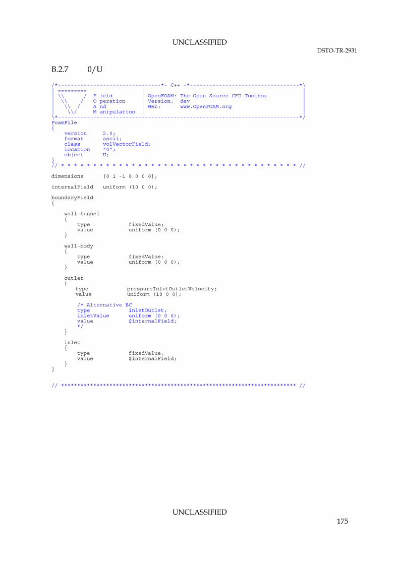
UNCLASSIFIED DSTO-TR-2931
UNCLASSIFIED 175
B.2.7 0/U
/*--------------------------------*- C++ -*----------------------------------*\ | ========= | | | \\ / F ield | OpenFOAM: The Open Source CFD Toolbox | | \\ / O peration | Version: dev | | \\ / A nd | Web: www.OpenFOAM.org | | \\/ M anipulation | | \*---------------------------------------------------------------------------*/ FoamFile { version 2.0; format ascii; class volVectorField; location "0"; object U; } // * * * * * * * * * * * * * * * * * * * * * * * * * * * * * * * * * * * * * // dimensions [0 1 -1 0 0 0 0]; internalField uniform (10 0 0); boundaryField { wall-tunnel { type fixedValue; value uniform (0 0 0); } wall-body { type fixedValue; value uniform (0 0 0); } outlet { type pressureInletOutletVelocity; value uniform (10 0 0); /* Alternative BC type inletOutlet; inletValue uniform (0 0 0); value $internalField; */ } inlet { type fixedValue; value $internalField; } } // ************************************************************************* //
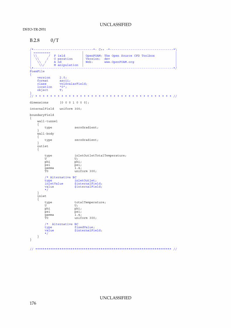
UNCLASSIFIED DSTO-TR-2931
UNCLASSIFIED 176
B.2.8 0/T
/*--------------------------------*- C++ -*----------------------------------*\ | ========= | | | \\ / F ield | OpenFOAM: The Open Source CFD Toolbox | | \\ / O peration | Version: dev | | \\ / A nd | Web: www.OpenFOAM.org | | \\/ M anipulation | | \*---------------------------------------------------------------------------*/ FoamFile { version 2.0; format ascii; class volScalarField; location "0"; object T; } // * * * * * * * * * * * * * * * * * * * * * * * * * * * * * * * * * * * * * // dimensions [0 0 0 1 0 0 0]; internalField uniform 300; boundaryField { wall-tunnel { type zeroGradient; } wall-body { type zeroGradient; } outlet { type inletOutletTotalTemperature; U U; phi phi; psi psi; gamma 1.4; T0 uniform 300; /* Alternative BC type inletOutlet; inletValue $internalField; value $internalField; */ } inlet { type totalTemperature; U U; phi phi; psi psi; gamma 1.4; T0 uniform 300; /* Alternative BC type fixedValue; value $internalField; */ } } // ************************************************************************* //

UNCLASSIFIED DSTO-TR-2931
UNCLASSIFIED 177
B.2.9 0/k
/*--------------------------------*- C++ -*----------------------------------*\ | ========= | | | \\ / F ield | OpenFOAM: The Open Source CFD Toolbox | | \\ / O peration | Version: 2.0.x | | \\ / A nd | Web: www.OpenFOAM.org | | \\/ M anipulation | | \*---------------------------------------------------------------------------*/ FoamFile { version 2.0; format ascii; class volScalarField; location "0"; object k; } // * * * * * * * * * * * * * * * * * * * * * * * * * * * * * * * * * * * * * // dimensions [0 2 -2 0 0 0 0]; internalField uniform 0.00375; boundaryField { wall-tunnel { type compressible::kqRWallFunction; value uniform 0.00375; } wall-body { type compressible::kqRWallFunction; value uniform 0.00375; } outlet { type inletOutlet; inletValue uniform 0.00375; value uniform 0.00375; } inlet { type turbulentIntensityKineticEnergyInlet; intensity 0.01; value uniform 12; //based on avgU of 10 m/s } } // ************************************************************************* //

UNCLASSIFIED DSTO-TR-2931
UNCLASSIFIED 178
B.2.10 0/epsilon
/*--------------------------------*- C++ -*----------------------------------*\ | ========= | | | \\ / F ield | OpenFOAM: The Open Source CFD Toolbox | | \\ / O peration | Version: 2.0.x | | \\ / A nd | Web: www.OpenFOAM.org | | \\/ M anipulation | | \*---------------------------------------------------------------------------*/ FoamFile { version 2.0; format ascii; class volScalarField; location "0"; object epsilon; } // * * * * * * * * * * * * * * * * * * * * * * * * * * * * * * * * * * * * * // dimensions [0 2 -3 0 0 0 0]; internalField uniform 0.0005; boundaryField { wall-tunnel { type compressible::epsilonWallFunction; Cmu 0.09; kappa 0.41; E 9.8; value uniform 0.0005; } wall-body { type compressible::epsilonWallFunction; Cmu 0.09; kappa 0.41; E 9.8; value uniform 0.0005; } outlet { type inletOutlet; inletValue uniform 0.0005; value uniform 0.0005; } inlet { type compressible::turbulentMixingLengthDissipationRateInlet; mixingLength 0.21; // 0.07 x Tunnel Dia value uniform 32; // based on k of 12 } } // ************************************************************************* //

UNCLASSIFIED DSTO-TR-2931
UNCLASSIFIED 179
B.2.11 0/mut
/*--------------------------------*- C++ -*----------------------------------*\ | ========= | | | \\ / F ield | OpenFOAM: The Open Source CFD Toolbox | | \\ / O peration | Version: 2.0.x | | \\ / A nd | Web: www.OpenFOAM.org | | \\/ M anipulation | | \*---------------------------------------------------------------------------*/ FoamFile { version 2.0; format ascii; class volScalarField; location "0"; object mut; } // * * * * * * * * * * * * * * * * * * * * * * * * * * * * * * * * * * * * * // dimensions [1 -1 -1 0 0 0 0]; internalField uniform 0; boundaryField { wall-tunnel { type mutkWallFunction; Cmu 0.09; kappa 0.41; E 9.8; value uniform 0; } wall-body { type mutkWallFunction; Cmu 0.09; kappa 0.41; E 9.8; value uniform 0; } outlet { type calculated; value uniform 0; } inlet { type calculated; value uniform 0; } } // ************************************************************************* //

UNCLASSIFIED DSTO-TR-2931
UNCLASSIFIED 180
B.2.12 0/alphat
/*--------------------------------*- C++ -*----------------------------------*\ | ========= | | | \\ / F ield | OpenFOAM: The Open Source CFD Toolbox | | \\ / O peration | Version: 2.0.x | | \\ / A nd | Web: www.OpenFOAM.org | | \\/ M anipulation | | \*---------------------------------------------------------------------------*/ FoamFile { version 2.0; format ascii; class volScalarField; location "0"; object alphat; } // * * * * * * * * * * * * * * * * * * * * * * * * * * * * * * * * * * * * * // dimensions [1 -1 -1 0 0 0 0]; internalField uniform 0; boundaryField { wall-tunnel { type alphatWallFunction; Prt 0.85; value uniform 0; } wall-body { type alphatWallFunction; Prt 0.85; value uniform 0; } outlet { type calculated; value uniform 0; } inlet { type calculated; value uniform 0; } } // ************************************************************************* //

UNCLASSIFIED DSTO-TR-2931
UNCLASSIFIED 181
B.2.13 system/controlDict
/*--------------------------------*- C++ -*----------------------------------*\ | ========= | | | \\ / F ield | OpenFOAM: The Open Source CFD Toolbox | | \\ / O peration | Version: dev | | \\ / A nd | Web: www.OpenFOAM.org | | \\/ M anipulation | | \*---------------------------------------------------------------------------*/ FoamFile { version 2.0; format ascii; class dictionary; object controlDict; } // * * * * * * * * * * * * * * * * * * * * * * * * * * * * * * * * * * * * * // libs ("librotorDiskSource.so"); application rhoSimpleSourceFoam; startFrom startTime; startTime 0; stopAt endTime; //writeNow; endTime 6000; deltaT 1; writeControl timeStep; writeInterval 1000; purgeWrite 5; writeFormat ascii; writePrecision 12; writeCompression uncompressed; timeFormat general; timePrecision 6; runTimeModifiable yes; // ************************************************************************* //

UNCLASSIFIED DSTO-TR-2931
UNCLASSIFIED 182
B.2.14 system/fvSchemes
/*--------------------------------*- C++ -*----------------------------------*\ | ========= | | | \\ / F ield | OpenFOAM: The Open Source CFD Toolbox | | \\ / O peration | Version: dev | | \\ / A nd | Web: www.OpenFOAM.org | | \\/ M anipulation | | \*---------------------------------------------------------------------------*/ FoamFile { version 2.0; format ascii; class dictionary; object fvSchemes; } // * * * * * * * * * * * * * * * * * * * * * * * * * * * * * * * * * * * * * // ddtSchemes { default steadyState; } gradSchemes { default leastSquares; //Gauss linear; //Gauss pointLinear; grad(p) Gauss linear; grad(U) faceLimited Gauss linear 1; limitedGrad(h) cellLimited Gauss linear 1; } divSchemes { default none; div(phi,U) Gauss upwind grad(U); //1st order upwind //div(phi,U) Gauss linearUpwindV grad(U); //2nd order blended upwind div(phi,h) Gauss upwind; //div(phi,h) Gauss linearUpwind limitedGrad(h); //2nd order blended upwind div(phi,k) Gauss upwind; div(phi,epsilon) Gauss upwind; div(phi,k) Gauss limitedLinear 0.5; // TVD 2nd Order Scheme div(phi,epsilon) Gauss limitedLinear 0.5; div(phi,K) Gauss upwind; div(U,p) Gauss linear; div((nuEff*dev(T(grad(U))))) Gauss linear; div((muEff*dev2(T(grad(U))))) Gauss linear; } laplacianSchemes { default Gauss linear limited 0.333; } interpolationSchemes { default linear; } snGradSchemes { default limited 0.333; } fluxRequired { default no; p; } // ************************************************************************* //

UNCLASSIFIED DSTO-TR-2931
UNCLASSIFIED 183
B.2.15 system/fvSolution
/*--------------------------------*- C++ -*----------------------------------*\ | ========= | | | \\ / F ield | OpenFOAM: The Open Source CFD Toolbox | | \\ / O peration | Version: dev | | \\ / A nd | Web: www.OpenFOAM.org | | \\/ M anipulation | | \*---------------------------------------------------------------------------*/ FoamFile { version 2.0; format ascii; class dictionary; object fvSolution; } // * * * * * * * * * * * * * * * * * * * * * * * * * * * * * * * * * * * * * // solvers { p { solver GAMG; tolerance 1e-7; relTol 0.1; smoother GaussSeidel; nPreSweeps 0; nPostSweeps 2; cacheAgglomeration on; agglomerator faceAreaPair; nCellsInCoarsestLevel 10; mergeLevels 1; } U { solver smoothSolver; smoother GaussSeidel; tolerance 1e-8; relTol 0.1; nSweeps 1; } k { solver smoothSolver; smoother GaussSeidel; tolerance 1e-8; relTol 0.1; nSweeps 1; } epsilon { solver smoothSolver; smoother GaussSeidel; tolerance 1e-8; relTol 0.1; nSweeps 1; } h { solver smoothSolver; smoother GaussSeidel; tolerance 1e-8; relTol 0.1; nSweeps 1; } } SIMPLE { nNonOrthogonalCorrectors 0; // pRefCell 0; // pRefValue 0;

UNCLASSIFIED DSTO-TR-2931
UNCLASSIFIED 184
rhoMin rhoMin [1 -3 0 0 0] 1; rhoMax rhoMax [1 -3 0 0 0] 1.4; residualControl { p 1e-8; U 1e-9; "(k|epsilon)" 1e-9; } } relaxationFactors { rho 1.0; p 0.2; U 0.3; k 0.3; epsilon 0.3; h 0.3; } cache { grad(U); } // ************************************************************************* //

UNCLASSIFIED DSTO-TR-2931
UNCLASSIFIED 185
B.2.16 system/decomposeParDict
/*--------------------------------*- C++ -*----------------------------------*\ | ========= | | | \\ / F ield | OpenFOAM: The Open Source CFD Toolbox | | \\ / O peration | Version: 1.7.0 | | \\ / A nd | Web: www.OpenFOAM.com | | \\/ M anipulation | | \*---------------------------------------------------------------------------*/ FoamFile { version 2.0; format ascii; class dictionary; object decomposeParDict; } // * * * * * * * * * * * * * * * * * * * * * * * * * * * * * * * * * * * * * // numberOfSubdomains 256; //method simple; //method metis; //method parMetis; method scotch; simpleCoeffs { n (28 1 1); delta 0.001; } hierarchicalCoeffs { n (4 2 1); delta 0.0001; order xyz; } manualCoeffs { dataFile "cellDecomposition"; } metisCoeffs { processorWeights (1 1 1 1 1 1 1 1 ); } distributed no; roots (); // ************************************************************************* //

UNCLASSIFIED DSTO-TR-2931
UNCLASSIFIED 186
B.2.17 monitorResiduals
# to run this script issue the commands: # $ gnuplot monitorResiduals set logscale y set grid plot "< cat script.log | grep Ux | cut -d' ' -f9 | tr -d ','" t "Ux" with lines, "< cat script.log | grep Uy | cut -d' ' -f9 | tr -d ','" t "Uy" with lines, "< cat script.log | grep 'for omega,'| cut -d' ' -f9 | tr -d ','" t "omega" with lines, "< cat script.log | grep Uz, | cut -d' ' -f9 | tr -d ','" t "Uz" with lines, "< cat script.log | grep 'for h,' | cut -d' ' -f9 | tr -d ','" t "energy" with lines, "< cat script.log | grep local | cut -d' ' -f9 | tr -d ','" t "local_continuity" with lines, "< cat script.log | grep 'for p,' | cut -d' ' -f9 | tr -d ','" t "p" with lines pause 1 # update interval (s) reread #live plotting mode #### Uncomment all four lines below to save the plot to a png file #### #set terminal png #set size 1,1 #set output "residuals.png" #replot # File name: save.plt - save a Gnuplot plot as a PostScript file # to save the current plot as a postscript file issue the commands: # gnuplot> load 'saveplot' # gnuplot> !mv my-plot.ps another-file.ps # set size 1.0, 0.6 # set terminal postscript portrait enhanced mono dashed lw 1 "Helvetica" 14 # set output "my-plot.ps" # replot

UNCLASSIFIED DSTO-TR-2931
UNCLASSIFIED 187
B.2.18 runCaseOnSeadragonCluster
#!/bin/bash # ### PBS ### #PBS -N GTITrimmed #PBS -S /bin/bash -j oe -k o -r n #PBS -l walltime=100:00:00 #PBS -l select=16:ncpus=16:mpiprocs=16 ### PBS -l select=32:ncpus=16:mpiprocs=16 ### PBS -l select=28:ncpus=16:mpiprocs=16 ### qsub -l select=8:ncpus=16:mpiprocs=16 ./Allrun ### ### select=number_of_nodes (1 to 32 nodes in cluster) ### ncpus=number_of_cores_per_node (for dual AMD 6220 processor nodes, ncpus=16) ### mpiprocs=number_of_mpi_processes_per_node (mpiprocs=16) ### source /data1/OpenFOAM/OpenFOAM-SGIRHEL62-2.1.X_X8664_07JUNE12_REPO/setup.sh DP SGIMPI export NCORES=`cat $PBS_NODEFILE | wc -l` ####################### cd $PBS_O_WORKDIR # NOTE THAT THIS SCRIPT MUST BE SUBMITTED FROM THE WORK DIRECTORY ####################### rm -rf processor* log logs script.log . $WM_PROJECT_DIR/bin/tools/RunFunctions unset FOAM_SIGFPE echo ' ' > script.log echo 'Starting the Run' >> script.log echo '==============================' >> script.log echo "PBS: Allocated $NCORES core(s) on node(s) "`cat $PBS_NODEFILE | sort -u` >> script.log echo "PBS: Submitted to $PBS_QUEUE@$PBS_O_HOST" >> script.log echo "PBS: Working directory is $PBS_O_WORKDIR" >> script.log echo "PBS: Job identifier is $PBS_JOBID" >> script.log echo "PBS: Job name is $PBS_JOBNAME" >> script.log echo '==============================' >> script.log echo ' ' # System variables HOST=`uname -n` OSTYPE=`uname -s` echo 'running on '$HOST $OSTYPE ' using mpi routine '$FOAM_MPI >> script.log echo '' >> script.log CURDIR=`pwd` runApplication foamInstallationTest cat log.foamInstallationTest >> script.log runApplication checkMesh cat log.checkMesh >> script.log # Tell PBS of available nodes on the cluster export MPI_DSM_CPULIST="0-15:allhosts" ### Add job sequence here ### decomposePar -force -cellDist > log.decomposePar 2>&1 cat log.decomposePar >> script.log foamJob -parallel -screen rhoSimpleSourceFoam >> script.log 2>&1 foamLog log reconstructPar > log.reconstructPar 2>&1 cat log.reconstructPar >> script.log rm -rf processor* echo '' echo =========================================== echo RUN IS FINISHED echo =========================================== echo ''

Page classification: UNCLASSIFIED
DEFENCE SCIENCE AND TECHNOLOGY ORGANISATION
DOCUMENT CONTROL DATA 1. DLM/CAVEAT (OF DOCUMENT)
2. TITLE Development of Virtual Blade Model for Modelling Helicopter Rotor Downwash in OpenFOAM
3. SECURITY CLASSIFICATION (FOR UNCLASSIFIED REPORTS THAT ARE LIMITED RELEASE USE (L) NEXT TO DOCUMENT CLASSIFICATION) Document (U) Title (U) Abstract (U)
4. AUTHOR(S) Stefano Wahono
5. CORPORATE AUTHOR DSTO Defence Science and Technology Organisation 506 Lorimer St Fishermans Bend Victoria 3207 Australia
6a. DSTO NUMBER DSTO-TR-2931
6b. AR NUMBER AR-015-836
6c. TYPE OF REPORT Technical Report
7. DOCUMENT DATE December 2013
8. FILE NUMBER 2013/1020983/1
9. TASK NUMBER 07/225
10. TASK SPONSOR Commander AOSG
11. NO. OF PAGES 188
12. NO. OF REFERENCES 26
13. DOWNGRADING/DELIMITING INSTRUCTIONS To be reviewed three years after date of publication
14. RELEASE AUTHORITY Chief, Aerospace Division
15. SECONDARY RELEASE STATEMENT OF THIS DOCUMENT Approved for Public release OVERSEAS ENQUIRIES OUTSIDE STATED LIMITATIONS SHOULD BE REFERRED THROUGH DOCUMENT EXCHANGE, PO BOX 1500, EDINBURGH, SA 5111 16. DELIBERATE ANNOUNCEMENT No Limitations 17. CITATION IN OTHER DOCUMENTS Yes 18. DSTO RESEARCH LIBRARY THESAURUS Computational Fluid Dynamics, CFD, rotor downwash, helicopter rotor, blade element, Infrared Signatures, OpenFOAM, ANSYS Fluent 19. ABSTRACT This report documents the development of a computational model to simulate the complex flow induced by helicopter rotors, using an open-source computational fluid dynamics (CFD) code, OpenFOAMTM. This computational code is now being used to perform large-scale multi-physics simulations of the flow field around helicopters including exhaust plumes and their airframe impingement. The rotor downwash model was validated against available experimental data on rotor-fuselage interactions published by the Georgia Institute of Technology. The OpenFOAM predicted result was also shown to compare favourably with ANSYS Fluent predictions.
Page classification: UNCLASSIFIED