Analysis of Crack Width Calculation of Steel Fibre and ...
8
50 DARNIOJI ARCHITEKTŪRA IR STATYBA 2014. No. 1(6) JOURNAL OF SUSTAINABLE ARCHITECTURE AND CIVIL ENGINEERING ISSN 2029–9990 Analysis of Crack Width Calculation of Steel Fibre and Ordinary Reinforced Concrete Flexural Members Šarūnas Kelpša * , Mindaugas Augonis, Mindaugas Daukšys, Algirdas Augonis Kaunas University of Technology, Faculty of Civil Engineering and Architecture, Studentu st. 48, LT-51367 Kaunas, Lithuania. *Corresponding author: [email protected] http://dx.doi.org/10.5755/j01.sace.6.1.6336 It is known that steel fibre can reduce the crack width of reinforced concrete flexural members however generally accepted crack width calculation method does not exist yet. The residual tensile strength which is used for crack width calculations should be obtained from tests. Three crack width calculation methods of steel fibre and ordinary reinforced concrete flexural members are discussed in this paper. All these methods have been derived using Eurocode 2 provisions, which are intended to the members without the fibre. Experimental cracking results of small cross section flexural members reinforced with steel fibre and ordinary reinforcement are also discussed. A scatter of the residual tensile strength which is obtained from three point bending test and its influence to the crack width is also reviewed briefly. Calculated crack widths are compared to the experimental results. It is determined that due to lack of the specimens the large deviations of residual flexural tensile strength can be obtained and it can cause the significant errors of calculated crack widths. Keywords: Steel fibre, residual tensile strength, crack width, CMOD, SFRC. 1. Introduction The application of steel fibre has been investigated over the past few decades. Today the steel fibre is commonly used in slabs on grade and sprayed concrete although other application areas exist. The wider practice of the fibre is still restricted because there is no generally accepted design method. Also, the application of the steel fibre in structural design is limited due to the efficiency of steel fibre which has to be established from tests every time (Jansson 2007; Ulbinas, 2012). Depending on fibre content and its parameters the steel fibre can change properties of concrete slightly: compressive, tensile strength and modulus of elasticity. However, the steel fibre changes a nature of concrete collapse most highly: steel fibres enhance the post-cracking properties of concrete and the collapse becomes more ductile. Steel fibre reinforced concrete (SFRC) has load bearing capacity even after cracking. Depending on the fibre parameters and the fibre content the post cracking strength can be higher or lower than the tensile (peak) strength of SFRC (Naaman, 2003; Ulbinas, 2012; Vandewalle, 2007). After the cracking of steel fibre and ordinary reinforced concrete members, the steel fibre can transfer tensile stresses across the cracks and so it leads to a reduction of the crack widths. When the residual tensile strength of SFRC is higher than the tensile strength, then strain/deflection hardening post cracking behaviour is achieved. In this case, more cracks will open if the load is still increasing after the cracking.. Whereas when the residual tensile strength is lower than the tensile strength of SFRC, then strain/ deflection softening behaviour is achieved and no more cracks will open. Depending on stress-strain distribution in the section, the strain hardening is achieved using larger amount of the fibre than for the case of deflection hardening behaviour (Jansson, 2007; Jansson et. al., 2008; Naaman, 2003). In order to determine material properties of the SFRC some different tests methods were proposed: three and four point bending tests, round and square panel tests, wedge splitting tests and uniaxial tension tests. It is established, that the size of specimens determines a scatter of results – as the cracked area is bigger as the scatter of the results is lower. Although the residual tensile stress (axial post- cracking strength) of SFRC is determined indirectly and with the large scatter of the results, however the three point bending test method is common, because of simplicity of it (Jansson, 2007; Jansson et. al., 2008; Parmentier et. al., 2008; Vandewalle et. al., 2008). The composite reinforcement (steel fibre and ordinary reinforcement) allows us to reduce the width of the cracks and to enhance stiffness of the flexural members. (Ulbinas, et. al. 2009). RILEM TC 162-TDF (hereafter RILEM) has published the recommendations in 2003 (RILEM TC 162-
Transcript of Analysis of Crack Width Calculation of Steel Fibre and ...
50
DARNIOJI ARCHITEKTŪRA IR STATYBA2014. No. 1(6)
JOURNAL OF SUSTAINABLE ARCHITECTURE AND CIVIL ENGINEERINGISSN 2029–9990
Analysis of Crack Width Calculation of Steel Fibre and Ordinary Reinforced Concrete Flexural Members
Šarūnas Kelpša*, Mindaugas Augonis, Mindaugas Daukšys, Algirdas Augonis
Kaunas University of Technology, Faculty of Civil Engineering and Architecture, Studentu st. 48, LT-51367 Kaunas, Lithuania.
*Corresponding author: [email protected]
http://dx.doi.org/10.5755/j01.sace.6.1.6336
It is known that steel fibre can reduce the crack width of reinforced concrete flexural members however generally accepted crack width calculation method does not exist yet. The residual tensile strength which is used for crack width calculations should be obtained from tests. Three crack width calculation methods of steel fibre and ordinary reinforced concrete flexural members are discussed in this paper. All these methods have been derived using Eurocode 2 provisions, which are intended to the members without the fibre. Experimental cracking results of small cross section flexural members reinforced with steel fibre and ordinary reinforcement are also discussed. A scatter of the residual tensile strength which is obtained from three point bending test and its influence to the crack width is also reviewed briefly. Calculated crack widths are compared to the experimental results. It is determined that due to lack of the specimens the large deviations of residual flexural tensile strength can be obtained and it can cause the significant errors of calculated crack widths.
Keywords: Steel fibre, residual tensile strength, crack width, CMOD, SFRC.
1. Introduction
The application of steel fibre has been investigated over the past few decades. Today the steel fibre is commonly used in slabs on grade and sprayed concrete although other application areas exist. The wider practice of the fibre is still restricted because there is no generally accepted design method. Also, the application of the steel fibre in structural design is limited due to the efficiency of steel fibre which has to be established from tests every time (Jansson 2007; Ulbinas, 2012).
Depending on fibre content and its parameters the steel fibre can change properties of concrete slightly: compressive, tensile strength and modulus of elasticity. However, the steel fibre changes a nature of concrete collapse most highly: steel fibres enhance the post-cracking properties of concrete and the collapse becomes more ductile. Steel fibre reinforced concrete (SFRC) has load bearing capacity even after cracking. Depending on the fibre parameters and the fibre content the post cracking strength can be higher or lower than the tensile (peak) strength of SFRC (Naaman, 2003; Ulbinas, 2012; Vandewalle, 2007).
After the cracking of steel fibre and ordinary reinforced concrete members, the steel fibre can transfer tensile stresses across the cracks and so it leads to a reduction of the crack widths. When the residual tensile strength of SFRC is higher than the tensile strength, then strain/deflection hardening post cracking behaviour is achieved. In this case,
more cracks will open if the load is still increasing after the cracking.. Whereas when the residual tensile strength is lower than the tensile strength of SFRC, then strain/deflection softening behaviour is achieved and no more cracks will open. Depending on stress-strain distribution in the section, the strain hardening is achieved using larger amount of the fibre than for the case of deflection hardening behaviour (Jansson, 2007; Jansson et. al., 2008; Naaman, 2003).
In order to determine material properties of the SFRC some different tests methods were proposed: three and four point bending tests, round and square panel tests, wedge splitting tests and uniaxial tension tests. It is established, that the size of specimens determines a scatter of results – as the cracked area is bigger as the scatter of the results is lower. Although the residual tensile stress (axial post-cracking strength) of SFRC is determined indirectly and with the large scatter of the results, however the three point bending test method is common, because of simplicity of it (Jansson, 2007; Jansson et. al., 2008; Parmentier et. al., 2008; Vandewalle et. al., 2008).
The composite reinforcement (steel fibre and ordinary reinforcement) allows us to reduce the width of the cracks and to enhance stiffness of the flexural members. (Ulbinas, et. al. 2009). RILEM TC 162-TDF (hereafter RILEM) has published the recommendations in 2003 (RILEM TC 162-
51
TDF 2003) and there is offered the crack width calculation method of steel fibre and ordinary reinforced concrete flexural members. In order to get a better agreement between tests and calculation results other scientists have analysed this method and made their corrections then (Jansson et. al., 2010; Löfgren, 2007).
The estimation of cracking moment and three crack width calculation methods of steel fibre and ordinary reinforced concrete flexural members are discussed in this article. In order to examine calculation results the experimental program was performed. The residual flexural tensile strength (fR,1) of SFRC, compressive and tensile strengths of concrete and the SFRC as well as modulus of elasticity of the concrete were measured during these tests. The crack widths of the small cross section flexural concrete members reinforced with steel fibre and ordinary reinforcement were also measured. The experimental crack widths of full scale beams reinforced with steel fibre and ordinary reinforcement were taken from the reference (Ulbinas 2012). Comprehensive analysis and the comparison of calculated crack widths and the experimental results are also executed in this paper.
2. Methods
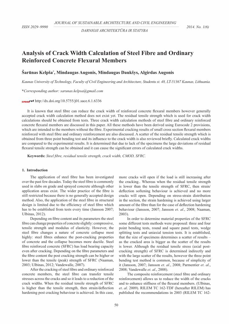
2.1. Verification of crack openingA cross section of SFRC member is uncracked until
tensile stress does not exceed the critical value. Theretofore by provisions of EC2 the full section is assumed to be elastic (Fig. 1). Steel fibre can change the tensile strength of concrete depending on fibre parameters. However in the calculations of the crack width opening of SFRC members it can be assumed approximately that the tensile strength of SFRC is equal to tensile strength of concrete (Jansson 2007). In more details, the tensile strength of SFRC is studied in the other publications – Naaman 2003, etc. In this case a cracking moment is calculated according to a formula (1):
reinforcement were also measured. The experimental crack
widths of full scale beams reinforced with steel fibre and
ordinary reinforcement were taken from the reference
(Ulbinas 2012). Comprehensive analysis and the
comparison of calculated crack widths and the experimental
results are also executed in this paper.
2. Methods
2.1. Verification of crack opening
A cross section of SFRC member is uncracked until
tensile stress does not exceed the critical value. Theretofore
by provisions of EC2 the full section is assumed to be
elastic (Fig. 1). Steel fibre can change the tensile strength of
concrete depending on fibre parameters. However in the
calculations of the crack width opening of SFRC members it
can be assumed approximately that the tensile strength of
SFRC is equal to tensile strength of concrete (Jansson
2007). In more details, the tensile strength of SFRC is
studied in the other publications – Naaman 2003, etc. In this
case a cracking moment is calculated according to a formula
(1):
elctmcrcWfM ⋅= ,
and strain distribution given in Fig. 1 (singly reinforced
section).
Fig. 1. Stress and strain distribution in uncracked section of SFRC
flexural member
The stress and strain distribution is analogical in
doubly reinforced section, but the top reinforcement should
be considered in that case.
2.2.Crack width calculation method proposed by RILEM TC
162-TDF
For the crack width calculation of steel fibre and
ordinary reinforced concrete members RILEM has proposed
an application of crack width calculation method given in
old ENV 1992-1-1:1991. The calculation method of ENV
1992-1-1:1991 was supplemented marginally. The
coefficient which reduces average crack spacing was
involved. This coefficient depends on parameters of the
steel fibre. Furthermore, the stress in tensile reinforcement
(σs and σ
sr) should be calculated considering that the steel
fibres, which cross the crack, take over the residual tensile
stresses (σfb
) uniformly through the all crack height. The
stress and strain distribution in the cracked section is given
in Fig. 2. In this case, the residual tensile stress is taken over
in a part of the crack height. Such stress distribution could
be obtained when the flexural member has a notch. Here afb
is the section height where the steel fibre does not take over
the residual tensile stress. In other cases, when there is no
factors, which can reduce the area of the residual tensile
stress, then afb
= 0.
Fig. 2. Stress and strain distribution in cracked section of SFRC
flexural member
The method proposed by RILEM indicates that the
residual tensile stress should be calculated according to the
formula (2) (RILEM TC 162-TDF 2003):
1,45.0
Rmfbf=σ ,
(2)
where: fRm,1
– the mean value of the flexural residual tensile
strength, obtained by three–point bending test method. In
more details this test are discussed in section 2.4.
According to the above discussed method the crack
width is calculated by the formula (3):
smrmksw εβ = ,
(3)
where: wk – the final crack width, s
rm – the average final
crack spacing, εsm
– the mean strain in the tension
reinforcement, β – coefficient relating the average crack
width with the design value (for load induced cracking β =
1.7).
The mean strain in the tension reinforcement εsm
is
calculated according to the formula (4):
⎥
⎥
⎦
⎤
⎢
⎢
⎣
⎡
⎟⎟
⎠
⎞
⎜⎜
⎝
⎛
−=
2
211
s
sr
s
s
sm
E σ
σ
ββ
σ
ε ,
(4)
where: σs – the stress in the tensile reinforcement calculated
on the basis of a cracked section (Fig. 2), σsr
– the stress in
the tensile reinforcement calculated on the basis of a
cracked section under loading conditions causing first
cracking (Fig. 2), β1 – coefficient which takes account of the
bond properties of the bars, β2 – coefficient which takes
account of the duration of the loading or of repeated
loading. The stresses in the tension reinforcement σs1
and
σsr1
can be obtained from the system of equilibrium
equations of forces and moments. This system for singly
reinforced SFRC flexural members (when afb
= 0) is given
in the equation (5):
(1)
where: fctm (fctm,fl) – mean value of axial (flexural) tensile strength of concrete (SFRC); Wel – elastic resisting moment of reinforced concrete member.
In analysis of the crack width which is given in section 3, the cracking moment is calculated according to a stress and strain distribution given in Fig. 1 (singly reinforced section).
Fig. 1. Stress and strain distribution in uncracked section of SFRC flexural member
The stress and strain distribution is analogical in doubly reinforced section, but the top reinforcement should be considered in that case.
2.2. Crack width calculation method proposed by RILEM TC 162-TDF
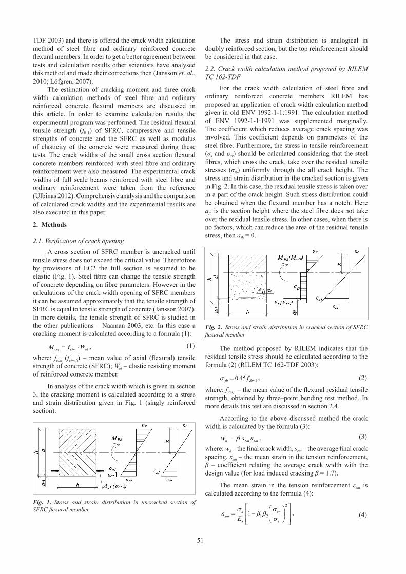
For the crack width calculation of steel fibre and ordinary reinforced concrete members RILEM has proposed an application of crack width calculation method given in old ENV 1992-1-1:1991. The calculation method of ENV 1992-1-1:1991 was supplemented marginally. The coefficient which reduces average crack spacing was involved. This coefficient depends on parameters of the steel fibre. Furthermore, the stress in tensile reinforcement (σs and σsr) should be calculated considering that the steel fibres, which cross the crack, take over the residual tensile stresses (σfb) uniformly through the all crack height. The stress and strain distribution in the cracked section is given in Fig. 2. In this case, the residual tensile stress is taken over in a part of the crack height. Such stress distribution could be obtained when the flexural member has a notch. Here afb is the section height where the steel fibre does not take over the residual tensile stress. In other cases, when there is no factors, which can reduce the area of the residual tensile stress, then afb = 0.
Fig. 2. Stress and strain distribution in cracked section of SFRC flexural member
The method proposed by RILEM indicates that the residual tensile stress should be calculated according to the formula (2) (RILEM TC 162-TDF 2003):
reinforcement were also measured. The experimental crack
widths of full scale beams reinforced with steel fibre and
ordinary reinforcement were taken from the reference
(Ulbinas 2012). Comprehensive analysis and the
comparison of calculated crack widths and the experimental
results are also executed in this paper.
2. Methods
2.1. Verification of crack opening
A cross section of SFRC member is uncracked until
tensile stress does not exceed the critical value. Theretofore
by provisions of EC2 the full section is assumed to be
elastic (Fig. 1). Steel fibre can change the tensile strength of
concrete depending on fibre parameters. However in the
calculations of the crack width opening of SFRC members it
can be assumed approximately that the tensile strength of
SFRC is equal to tensile strength of concrete (Jansson
2007). In more details, the tensile strength of SFRC is
studied in the other publications – Naaman 2003, etc. In this
case a cracking moment is calculated according to a formula
(1):
elctmcrcWfM ⋅= ,
and strain distribution given in Fig. 1 (singly reinforced
section).
Fig. 1. Stress and strain distribution in uncracked section of SFRC
flexural member
The stress and strain distribution is analogical in
doubly reinforced section, but the top reinforcement should
be considered in that case.
2.2.Crack width calculation method proposed by RILEM TC
162-TDF
For the crack width calculation of steel fibre and
ordinary reinforced concrete members RILEM has proposed
an application of crack width calculation method given in
old ENV 1992-1-1:1991. The calculation method of ENV
1992-1-1:1991 was supplemented marginally. The
coefficient which reduces average crack spacing was
involved. This coefficient depends on parameters of the
steel fibre. Furthermore, the stress in tensile reinforcement
(σs and σ
sr) should be calculated considering that the steel
fibres, which cross the crack, take over the residual tensile
stresses (σfb
) uniformly through the all crack height. The
stress and strain distribution in the cracked section is given
in Fig. 2. In this case, the residual tensile stress is taken over
in a part of the crack height. Such stress distribution could
be obtained when the flexural member has a notch. Here afb
is the section height where the steel fibre does not take over
the residual tensile stress. In other cases, when there is no
factors, which can reduce the area of the residual tensile
stress, then afb
= 0.
Fig. 2. Stress and strain distribution in cracked section of SFRC
flexural member
The method proposed by RILEM indicates that the
residual tensile stress should be calculated according to the
formula (2) (RILEM TC 162-TDF 2003):
1,45.0
Rmfbf=σ ,
(2)
where: fRm,1
– the mean value of the flexural residual tensile
strength, obtained by three–point bending test method. In
more details this test are discussed in section 2.4.
According to the above discussed method the crack
width is calculated by the formula (3):
smrmksw εβ = ,
(3)
where: wk – the final crack width, s
rm – the average final
crack spacing, εsm
– the mean strain in the tension
reinforcement, β – coefficient relating the average crack
width with the design value (for load induced cracking β =
1.7).
The mean strain in the tension reinforcement εsm
is
calculated according to the formula (4):
⎥
⎥
⎦
⎤
⎢
⎢
⎣
⎡
⎟⎟
⎠
⎞
⎜⎜
⎝
⎛
−=
2
211
s
sr
s
s
sm
E σ
σ
ββ
σ
ε ,
(4)
where: σs – the stress in the tensile reinforcement calculated
on the basis of a cracked section (Fig. 2), σsr
– the stress in
the tensile reinforcement calculated on the basis of a
cracked section under loading conditions causing first
cracking (Fig. 2), β1 – coefficient which takes account of the
bond properties of the bars, β2 – coefficient which takes
account of the duration of the loading or of repeated
loading. The stresses in the tension reinforcement σs1
and
σsr1
can be obtained from the system of equilibrium
equations of forces and moments. This system for singly
reinforced SFRC flexural members (when afb
= 0) is given
in the equation (5):
(2)
where: fRm,1 – the mean value of the flexural residual tensile strength, obtained by three–point bending test method. In more details this test are discussed in section 2.4.
According to the above discussed method the crack width is calculated by the formula (3):
reinforcement were also measured. The experimental crack
widths of full scale beams reinforced with steel fibre and
ordinary reinforcement were taken from the reference
(Ulbinas 2012). Comprehensive analysis and the
comparison of calculated crack widths and the experimental
results are also executed in this paper.
2. Methods
2.1. Verification of crack opening
A cross section of SFRC member is uncracked until
tensile stress does not exceed the critical value. Theretofore
by provisions of EC2 the full section is assumed to be
elastic (Fig. 1). Steel fibre can change the tensile strength of
concrete depending on fibre parameters. However in the
calculations of the crack width opening of SFRC members it
can be assumed approximately that the tensile strength of
SFRC is equal to tensile strength of concrete (Jansson
2007). In more details, the tensile strength of SFRC is
studied in the other publications – Naaman 2003, etc. In this
case a cracking moment is calculated according to a formula
(1):
elctmcrcWfM ⋅= ,
and strain distribution given in Fig. 1 (singly reinforced
section).
Fig. 1. Stress and strain distribution in uncracked section of SFRC
flexural member
The stress and strain distribution is analogical in
doubly reinforced section, but the top reinforcement should
be considered in that case.
2.2.Crack width calculation method proposed by RILEM TC
162-TDF
For the crack width calculation of steel fibre and
ordinary reinforced concrete members RILEM has proposed
an application of crack width calculation method given in
old ENV 1992-1-1:1991. The calculation method of ENV
1992-1-1:1991 was supplemented marginally. The
coefficient which reduces average crack spacing was
involved. This coefficient depends on parameters of the
steel fibre. Furthermore, the stress in tensile reinforcement
(σs and σ
sr) should be calculated considering that the steel
fibres, which cross the crack, take over the residual tensile
stresses (σfb
) uniformly through the all crack height. The
stress and strain distribution in the cracked section is given
in Fig. 2. In this case, the residual tensile stress is taken over
in a part of the crack height. Such stress distribution could
be obtained when the flexural member has a notch. Here afb
is the section height where the steel fibre does not take over
the residual tensile stress. In other cases, when there is no
factors, which can reduce the area of the residual tensile
stress, then afb
= 0.
Fig. 2. Stress and strain distribution in cracked section of SFRC
flexural member
The method proposed by RILEM indicates that the
residual tensile stress should be calculated according to the
formula (2) (RILEM TC 162-TDF 2003):
1,45.0
Rmfbf=σ ,
(2)
where: fRm,1
– the mean value of the flexural residual tensile
strength, obtained by three–point bending test method. In
more details this test are discussed in section 2.4.
According to the above discussed method the crack
width is calculated by the formula (3):
smrmksw εβ = ,
(3)
where: wk – the final crack width, s
rm – the average final
crack spacing, εsm
– the mean strain in the tension
reinforcement, β – coefficient relating the average crack
width with the design value (for load induced cracking β =
1.7).
The mean strain in the tension reinforcement εsm
is
calculated according to the formula (4):
⎥
⎥
⎦
⎤
⎢
⎢
⎣
⎡
⎟⎟
⎠
⎞
⎜⎜
⎝
⎛
−=
2
211
s
sr
s
s
sm
E σ
σ
ββ
σ
ε ,
(4)
where: σs – the stress in the tensile reinforcement calculated
on the basis of a cracked section (Fig. 2), σsr
– the stress in
the tensile reinforcement calculated on the basis of a
cracked section under loading conditions causing first
cracking (Fig. 2), β1 – coefficient which takes account of the
bond properties of the bars, β2 – coefficient which takes
account of the duration of the loading or of repeated
loading. The stresses in the tension reinforcement σs1
and
σsr1
can be obtained from the system of equilibrium
equations of forces and moments. This system for singly
reinforced SFRC flexural members (when afb
= 0) is given
in the equation (5):
(3)
where: wk – the final crack width, srm – the average final crack spacing, εsm – the mean strain in the tension reinforcement, β – coefficient relating the average crack width with the design value (for load induced cracking β = 1.7).
The mean strain in the tension reinforcement εsm is calculated according to the formula (4):
reinforcement were also measured. The experimental crack
widths of full scale beams reinforced with steel fibre and
ordinary reinforcement were taken from the reference
(Ulbinas 2012). Comprehensive analysis and the
comparison of calculated crack widths and the experimental
results are also executed in this paper.
2. Methods
2.1. Verification of crack opening
A cross section of SFRC member is uncracked until
tensile stress does not exceed the critical value. Theretofore
by provisions of EC2 the full section is assumed to be
elastic (Fig. 1). Steel fibre can change the tensile strength of
concrete depending on fibre parameters. However in the
calculations of the crack width opening of SFRC members it
can be assumed approximately that the tensile strength of
SFRC is equal to tensile strength of concrete (Jansson
2007). In more details, the tensile strength of SFRC is
studied in the other publications – Naaman 2003, etc. In this
case a cracking moment is calculated according to a formula
(1):
elctmcrcWfM ⋅= ,
and strain distribution given in Fig. 1 (singly reinforced
section).
Fig. 1. Stress and strain distribution in uncracked section of SFRC
flexural member
The stress and strain distribution is analogical in
doubly reinforced section, but the top reinforcement should
be considered in that case.
2.2.Crack width calculation method proposed by RILEM TC
162-TDF
For the crack width calculation of steel fibre and
ordinary reinforced concrete members RILEM has proposed
an application of crack width calculation method given in
old ENV 1992-1-1:1991. The calculation method of ENV
1992-1-1:1991 was supplemented marginally. The
coefficient which reduces average crack spacing was
involved. This coefficient depends on parameters of the
steel fibre. Furthermore, the stress in tensile reinforcement
(σs and σ
sr) should be calculated considering that the steel
fibres, which cross the crack, take over the residual tensile
stresses (σfb
) uniformly through the all crack height. The
stress and strain distribution in the cracked section is given
in Fig. 2. In this case, the residual tensile stress is taken over
in a part of the crack height. Such stress distribution could
be obtained when the flexural member has a notch. Here afb
is the section height where the steel fibre does not take over
the residual tensile stress. In other cases, when there is no
factors, which can reduce the area of the residual tensile
stress, then afb
= 0.
Fig. 2. Stress and strain distribution in cracked section of SFRC
flexural member
The method proposed by RILEM indicates that the
residual tensile stress should be calculated according to the
formula (2) (RILEM TC 162-TDF 2003):
1,45.0
Rmfbf=σ ,
(2)
where: fRm,1
– the mean value of the flexural residual tensile
strength, obtained by three–point bending test method. In
more details this test are discussed in section 2.4.
According to the above discussed method the crack
width is calculated by the formula (3):
smrmksw εβ = ,
(3)
where: wk – the final crack width, s
rm – the average final
crack spacing, εsm
– the mean strain in the tension
reinforcement, β – coefficient relating the average crack
width with the design value (for load induced cracking β =
1.7).
The mean strain in the tension reinforcement εsm
is
calculated according to the formula (4):
⎥
⎥
⎦
⎤
⎢
⎢
⎣
⎡
⎟⎟
⎠
⎞
⎜⎜
⎝
⎛
−=
2
211
s
sr
s
s
sm
E σ
σ
ββ
σ
ε ,
(4)
where: σs – the stress in the tensile reinforcement calculated
on the basis of a cracked section (Fig. 2), σsr
– the stress in
the tensile reinforcement calculated on the basis of a
cracked section under loading conditions causing first
cracking (Fig. 2), β1 – coefficient which takes account of the
bond properties of the bars, β2 – coefficient which takes
account of the duration of the loading or of repeated
loading. The stresses in the tension reinforcement σs1
and
σsr1
can be obtained from the system of equilibrium
equations of forces and moments. This system for singly
reinforced SFRC flexural members (when afb
= 0) is given
in the equation (5):
(4)
52
where: σs – the stress in the tensile reinforcement calculated on the basis of a cracked section (Fig. 2), σsr – the stress in the tensile reinforcement calculated on the basis of a cracked section under loading conditions causing first cracking (Fig. 2), β1 – coefficient which takes account of the bond properties of the bars, β2 – coefficient which takes account of the duration of the loading or of repeated loading. The stresses in the tension reinforcement σs1 and σsr1 can be obtained from the system of equilibrium equations of forces and moments. This system for singly reinforced SFRC flexural members (when afb = 0) is given in the equation (5):
( )
( )
( )⎪
⎪
⎩
⎪⎪
⎨
⎧
=−⎟
⎠
⎞
⎜
⎝
⎛−+⎟
⎠
⎞
⎜
⎝
⎛+−
=−−−
−
0
362
0
2
11
11
2
1
Ekssfb
fbss
e
s
M
x
dAσ
xh
xhbσ
xhbσAσ
xdα
bxσ
,
(5)
The average crack spacing srm
is calculated according
to the formula (6):
⎟⎟
⎠
⎞
⎜⎜
⎝
⎛
⎟⎟
⎠
⎞
⎜⎜
⎝
⎛
+=
φρ
φ
/
50
25.05021
L
kks
r
b
rm
,
(6)
where: b – reinforcement bar diameter, k
1 – a coefficient
which takes account of the bond properties of the
reinforcement, k2 – a coefficient which takes account of the
form of strain distribution, ρr – the effective reinforcement
ratio (As1
/Ac,eff
), L – steel fibre length, – steel fibre
diameter. 50/(L/ ) ≤ 1 – a RILEM proposed coefficient,
which considers the influence of the steel fibre on the
average crack spacing. However, this coefficient only
considers the influence of length and diameter of the steel
fibre, but it does not consider the fibre content.
It is also important to note the fact for the flexural
members the effective tension area (Ac,eff
) should be lesser
value of 2.5b(h – d) or b(h – x)/3. When the depth of tension
zone is small enough, then the second expression is used to
determine the effective tension area of the concrete (ENV
1992-1-1:1991, EN 1992-1-1:2004).
2.3. Supplemented and corrected EN 1992-1-1:2004 crack
width calculation methods
It is possible to calculate the crack width of steel fibre
and ordinary reinforced concrete flexural members
according to a new EN 1992-1-1:2004 (hereafter EC2)
method. However it should be done some modifications,
analogical as in RILEM method. Here the crack width is
calculated according to the formula (7) (supplemented
method of EC2).
( )cmsmr,kεεsw −=
max
, (7)
where: sr,max
– the maximum crack spacing; εsm
– the mean
strain in the reinforcement; εcm
– the mean strain in the
concrete between the cracks.
The difference of the strain (εsm
and εcm
):
( )
s
s
s
effpe
effp
effct
ts
cmsm
EE
f
k
σ
ρα
ρ
σ
εε 6.0
1,
,
,
≥
+−
=− ,
(8)
where: σs – the stress in the tension reinforcement assuming
the cracked section. Determination of σs was discused above
(Fig. 2). kt – a factor dependent on the duration of the load,
fct,eff
– the mean value of the tensile strength of the concrete
effective at the time when the cracks may first be expected
to occur, ρp,eff
– reinforcement ratio for longitudinal
reinforcement (ρp,eff
= ρr), α
e – ratio E
s/E
cm, where E
cm and
Es is the secant modulus of elasticity of the concrete and the
steel bars.
The expression of the maximum crack spacing is also
supplemented with the coefficient which was suggested by
RILEM. Then the maximum crack spacing:
⎟⎟
⎠
⎞
⎜⎜
⎝
⎛
⎟
⎟
⎠
⎞
⎜
⎜
⎝
⎛
+=
φρ
φ
/
50
425.04.3
,
21max,
L
kkcs
effp
r
,
(9)
where: c – the cover to the longitudinal reinforcement, ρp,eff
– the effective reinforcement ratio, – the reinforcement
bar diameter, k1 – the coefficient which takes account of the
bond properties of the bonded reinforcement, k2 – the
coefficient which takes account of the distribution of strain.
The coefficients k1 and k
2 are the same as in RILEM
method.
However, the RILEM proposed coefficient (50/(L/ ))
does not reflect accurately the influence of the fibre content
on the distance between the cracks. Whereas the crack
spacing differs together with the change of the fibre content,
therefore Löfgren, Jansson and the others have proposed the
slightly different expression (10) of the maximum crack
spacing in their publications (Jansson et. al. 2010, Löfgren
2007). There is no RILEM proposed coefficient in this
expression, however the coefficient k5 is used to reduce
maximum crack spacing depending on the residual tensile
stress. Whereas the residual tensile stress depends on the
parameters of steel fibre (aspect ratio – lfb
/dfb
), therefore this
coefficient also considers aspect ratio.
effp
rkkkcs
,
521max,425.04.3
ρ
φ
+= , (10)
where: the discussed coefficient k5 is calculated according to
the formula (11). The other coefficients were discussed
above.
⎟⎟
⎠
⎞
⎜⎜
⎝
⎛
−=
ctm
resft
f
f
k.
51 , (11)
where: fft.res
– the residual tensile stress of SFRC (fft.res
= σfb
).
2.4. Experimental program
The experimental program was performed in Kaunas
University of Technology in order to determine the
influence of the steel fibre for the cracking of steel fibre and
ordinary reinforced concrete flexural members. During the
experiments the influence of F–CMOD (Load – crack
mouth opening displacement) was obtained and then the
residual flexural tensile strength (fR,1
) and limit of
proportionality (LOP) were estimated. These tests were
performed according to requirements of the EN
14651:2005+A1:2007 standard, which is analogical as given
in RILEM TC 162-TDF (2002). The tests were performed
under CMOD control. The test scheme is given in Fig. 3.
. (5)
The average crack spacing srm is calculated according to the formula (6):
( )
( )
( )⎪
⎪
⎩
⎪⎪
⎨
⎧
=−⎟
⎠
⎞
⎜
⎝
⎛−+⎟
⎠
⎞
⎜
⎝
⎛+−
=−−−
−
0
362
0
2
11
11
2
1
Ekssfb
fbss
e
s
M
x
dAσ
xh
xhbσ
xhbσAσ
xdα
bxσ
,
(5)
The average crack spacing srm
is calculated according
to the formula (6):
⎟⎟
⎠
⎞
⎜⎜
⎝
⎛
⎟⎟
⎠
⎞
⎜⎜
⎝
⎛
+=
φρ
φ
/
50
25.05021
L
kks
r
b
rm
,
(6)
where: b – reinforcement bar diameter, k
1 – a coefficient
which takes account of the bond properties of the
reinforcement, k2 – a coefficient which takes account of the
form of strain distribution, ρr – the effective reinforcement
ratio (As1
/Ac,eff
), L – steel fibre length, – steel fibre
diameter. 50/(L/ ) ≤ 1 – a RILEM proposed coefficient,
which considers the influence of the steel fibre on the
average crack spacing. However, this coefficient only
considers the influence of length and diameter of the steel
fibre, but it does not consider the fibre content.
It is also important to note the fact for the flexural
members the effective tension area (Ac,eff
) should be lesser
value of 2.5b(h – d) or b(h – x)/3. When the depth of tension
zone is small enough, then the second expression is used to
determine the effective tension area of the concrete (ENV
1992-1-1:1991, EN 1992-1-1:2004).
2.3. Supplemented and corrected EN 1992-1-1:2004 crack
width calculation methods
It is possible to calculate the crack width of steel fibre
and ordinary reinforced concrete flexural members
according to a new EN 1992-1-1:2004 (hereafter EC2)
method. However it should be done some modifications,
analogical as in RILEM method. Here the crack width is
calculated according to the formula (7) (supplemented
method of EC2).
( )cmsmr,kεεsw −=
max
, (7)
where: sr,max
– the maximum crack spacing; εsm
– the mean
strain in the reinforcement; εcm
– the mean strain in the
concrete between the cracks.
The difference of the strain (εsm
and εcm
):
( )
s
s
s
effpe
effp
effct
ts
cmsm
EE
f
k
σ
ρα
ρ
σ
εε 6.0
1,
,
,
≥
+−
=− ,
(8)
where: σs – the stress in the tension reinforcement assuming
the cracked section. Determination of σs was discused above
(Fig. 2). kt – a factor dependent on the duration of the load,
fct,eff
– the mean value of the tensile strength of the concrete
effective at the time when the cracks may first be expected
to occur, ρp,eff
– reinforcement ratio for longitudinal
reinforcement (ρp,eff
= ρr), α
e – ratio E
s/E
cm, where E
cm and
Es is the secant modulus of elasticity of the concrete and the
steel bars.
The expression of the maximum crack spacing is also
supplemented with the coefficient which was suggested by
RILEM. Then the maximum crack spacing:
⎟⎟
⎠
⎞
⎜⎜
⎝
⎛
⎟
⎟
⎠
⎞
⎜
⎜
⎝
⎛
+=
φρ
φ
/
50
425.04.3
,
21max,
L
kkcs
effp
r
,
(9)
where: c – the cover to the longitudinal reinforcement, ρp,eff
– the effective reinforcement ratio, – the reinforcement
bar diameter, k1 – the coefficient which takes account of the
bond properties of the bonded reinforcement, k2 – the
coefficient which takes account of the distribution of strain.
The coefficients k1 and k
2 are the same as in RILEM
method.
However, the RILEM proposed coefficient (50/(L/ ))
does not reflect accurately the influence of the fibre content
on the distance between the cracks. Whereas the crack
spacing differs together with the change of the fibre content,
therefore Löfgren, Jansson and the others have proposed the
slightly different expression (10) of the maximum crack
spacing in their publications (Jansson et. al. 2010, Löfgren
2007). There is no RILEM proposed coefficient in this
expression, however the coefficient k5 is used to reduce
maximum crack spacing depending on the residual tensile
stress. Whereas the residual tensile stress depends on the
parameters of steel fibre (aspect ratio – lfb
/dfb
), therefore this
coefficient also considers aspect ratio.
effp
rkkkcs
,
521max,425.04.3
ρ
φ
+= , (10)
where: the discussed coefficient k5 is calculated according to
the formula (11). The other coefficients were discussed
above.
⎟⎟
⎠
⎞
⎜⎜
⎝
⎛
−=
ctm
resft
f
f
k.
51 , (11)
where: fft.res
– the residual tensile stress of SFRC (fft.res
= σfb
).
2.4. Experimental program
The experimental program was performed in Kaunas
University of Technology in order to determine the
influence of the steel fibre for the cracking of steel fibre and
ordinary reinforced concrete flexural members. During the
experiments the influence of F–CMOD (Load – crack
mouth opening displacement) was obtained and then the
residual flexural tensile strength (fR,1
) and limit of
proportionality (LOP) were estimated. These tests were
performed according to requirements of the EN
14651:2005+A1:2007 standard, which is analogical as given
in RILEM TC 162-TDF (2002). The tests were performed
under CMOD control. The test scheme is given in Fig. 3.
(6)
where: φb – reinforcement bar diameter, k1 – a coefficient which takes account of the bond properties of the reinforcement, k2 – a coefficient which takes account of the form of strain distribution, ρr – the effective reinforcement ratio (As1/Ac,eff), L – steel fibre length, φ – steel fibre diameter. 50/(L/φ) ≤ 1 – a RILEM proposed coefficient, which considers the influence of the steel fibre on the average crack spacing. However, this coefficient only considers the influence of length and diameter of the steel fibre, but it does not consider the fibre content.
It is also important to note the fact for the flexural members the effective tension area (Ac,eff) should be lesser value of 2.5b(h – d) or b(h – x)/3. When the depth of tension zone is small enough, then the second expression is used to determine the effective tension area of the concrete (ENV 1992-1-1:1991, EN 1992-1-1:2004).
2.3. Supplemented and corrected EN 1992-1-1:2004 crack width calculation methods
It is possible to calculate the crack width of steel fibre and ordinary reinforced concrete flexural members according to a new EN 1992-1-1:2004 (hereafter EC2) method. However it should be done some modifications, analogical as in RILEM method. Here the crack width is calculated according to the formula (7) (supplemented method of EC2).
( )
( )
( )⎪
⎪
⎩
⎪⎪
⎨
⎧
=−⎟
⎠
⎞
⎜
⎝
⎛−+⎟
⎠
⎞
⎜
⎝
⎛+−
=−−−
−
0
362
0
2
11
11
2
1
Ekssfb
fbss
e
s
M
x
dAσ
xh
xhbσ
xhbσAσ
xdα
bxσ
,
(5)
The average crack spacing srm
is calculated according
to the formula (6):
⎟⎟
⎠
⎞
⎜⎜
⎝
⎛
⎟⎟
⎠
⎞
⎜⎜
⎝
⎛
+=
φρ
φ
/
50
25.05021
L
kks
r
b
rm
,
(6)
where: b – reinforcement bar diameter, k
1 – a coefficient
which takes account of the bond properties of the
reinforcement, k2 – a coefficient which takes account of the
form of strain distribution, ρr – the effective reinforcement
ratio (As1
/Ac,eff
), L – steel fibre length, – steel fibre
diameter. 50/(L/ ) ≤ 1 – a RILEM proposed coefficient,
which considers the influence of the steel fibre on the
average crack spacing. However, this coefficient only
considers the influence of length and diameter of the steel
fibre, but it does not consider the fibre content.
It is also important to note the fact for the flexural
members the effective tension area (Ac,eff
) should be lesser
value of 2.5b(h – d) or b(h – x)/3. When the depth of tension
zone is small enough, then the second expression is used to
determine the effective tension area of the concrete (ENV
1992-1-1:1991, EN 1992-1-1:2004).
2.3. Supplemented and corrected EN 1992-1-1:2004 crack
width calculation methods
It is possible to calculate the crack width of steel fibre
and ordinary reinforced concrete flexural members
according to a new EN 1992-1-1:2004 (hereafter EC2)
method. However it should be done some modifications,
analogical as in RILEM method. Here the crack width is
calculated according to the formula (7) (supplemented
method of EC2).
( )cmsmr,kεεsw −=
max
, (7)
where: sr,max
– the maximum crack spacing; εsm
– the mean
strain in the reinforcement; εcm
– the mean strain in the
concrete between the cracks.
The difference of the strain (εsm
and εcm
):
( )
s
s
s
effpe
effp
effct
ts
cmsm
EE
f
k
σ
ρα
ρ
σ
εε 6.0
1,
,
,
≥
+−
=− ,
(8)
where: σs – the stress in the tension reinforcement assuming
the cracked section. Determination of σs was discused above
(Fig. 2). kt – a factor dependent on the duration of the load,
fct,eff
– the mean value of the tensile strength of the concrete
effective at the time when the cracks may first be expected
to occur, ρp,eff
– reinforcement ratio for longitudinal
reinforcement (ρp,eff
= ρr), α
e – ratio E
s/E
cm, where E
cm and
Es is the secant modulus of elasticity of the concrete and the
steel bars.
The expression of the maximum crack spacing is also
supplemented with the coefficient which was suggested by
RILEM. Then the maximum crack spacing:
⎟⎟
⎠
⎞
⎜⎜
⎝
⎛
⎟
⎟
⎠
⎞
⎜
⎜
⎝
⎛
+=
φρ
φ
/
50
425.04.3
,
21max,
L
kkcs
effp
r
,
(9)
where: c – the cover to the longitudinal reinforcement, ρp,eff
– the effective reinforcement ratio, – the reinforcement
bar diameter, k1 – the coefficient which takes account of the
bond properties of the bonded reinforcement, k2 – the
coefficient which takes account of the distribution of strain.
The coefficients k1 and k
2 are the same as in RILEM
method.
However, the RILEM proposed coefficient (50/(L/ ))
does not reflect accurately the influence of the fibre content
on the distance between the cracks. Whereas the crack
spacing differs together with the change of the fibre content,
therefore Löfgren, Jansson and the others have proposed the
slightly different expression (10) of the maximum crack
spacing in their publications (Jansson et. al. 2010, Löfgren
2007). There is no RILEM proposed coefficient in this
expression, however the coefficient k5 is used to reduce
maximum crack spacing depending on the residual tensile
stress. Whereas the residual tensile stress depends on the
parameters of steel fibre (aspect ratio – lfb
/dfb
), therefore this
coefficient also considers aspect ratio.
effp
rkkkcs
,
521max,425.04.3
ρ
φ
+= , (10)
where: the discussed coefficient k5 is calculated according to
the formula (11). The other coefficients were discussed
above.
⎟⎟
⎠
⎞
⎜⎜
⎝
⎛
−=
ctm
resft
f
f
k.
51 , (11)
where: fft.res
– the residual tensile stress of SFRC (fft.res
= σfb
).
2.4. Experimental program
The experimental program was performed in Kaunas
University of Technology in order to determine the
influence of the steel fibre for the cracking of steel fibre and
ordinary reinforced concrete flexural members. During the
experiments the influence of F–CMOD (Load – crack
mouth opening displacement) was obtained and then the
residual flexural tensile strength (fR,1
) and limit of
proportionality (LOP) were estimated. These tests were
performed according to requirements of the EN
14651:2005+A1:2007 standard, which is analogical as given
in RILEM TC 162-TDF (2002). The tests were performed
under CMOD control. The test scheme is given in Fig. 3.
(7)
where: sr,max – the maximum crack spacing; εsm – the mean strain in the reinforcement; εcm – the mean strain in the concrete between the cracks.
The difference of the strain (εsm and εcm):
( )
( )
( )⎪
⎪
⎩
⎪⎪
⎨
⎧
=−⎟
⎠
⎞
⎜
⎝
⎛−+⎟
⎠
⎞
⎜
⎝
⎛+−
=−−−
−
0
362
0
2
11
11
2
1
Ekssfb
fbss
e
s
M
x
dAσ
xh
xhbσ
xhbσAσ
xdα
bxσ
,
(5)
The average crack spacing srm
is calculated according
to the formula (6):
⎟⎟
⎠
⎞
⎜⎜
⎝
⎛
⎟⎟
⎠
⎞
⎜⎜
⎝
⎛
+=
φρ
φ
/
50
25.05021
L
kks
r
b
rm
,
(6)
where: b – reinforcement bar diameter, k
1 – a coefficient
which takes account of the bond properties of the
reinforcement, k2 – a coefficient which takes account of the
form of strain distribution, ρr – the effective reinforcement
ratio (As1
/Ac,eff
), L – steel fibre length, – steel fibre
diameter. 50/(L/ ) ≤ 1 – a RILEM proposed coefficient,
which considers the influence of the steel fibre on the
average crack spacing. However, this coefficient only
considers the influence of length and diameter of the steel
fibre, but it does not consider the fibre content.
It is also important to note the fact for the flexural
members the effective tension area (Ac,eff
) should be lesser
value of 2.5b(h – d) or b(h – x)/3. When the depth of tension
zone is small enough, then the second expression is used to
determine the effective tension area of the concrete (ENV
1992-1-1:1991, EN 1992-1-1:2004).
2.3. Supplemented and corrected EN 1992-1-1:2004 crack
width calculation methods
It is possible to calculate the crack width of steel fibre
and ordinary reinforced concrete flexural members
according to a new EN 1992-1-1:2004 (hereafter EC2)
method. However it should be done some modifications,
analogical as in RILEM method. Here the crack width is
calculated according to the formula (7) (supplemented
method of EC2).
( )cmsmr,kεεsw −=
max
, (7)
where: sr,max
– the maximum crack spacing; εsm
– the mean
strain in the reinforcement; εcm
– the mean strain in the
concrete between the cracks.
The difference of the strain (εsm
and εcm
):
( )
s
s
s
effpe
effp
effct
ts
cmsm
EE
f
k
σ
ρα
ρ
σ
εε 6.0
1,
,
,
≥
+−
=− ,
(8)
where: σs – the stress in the tension reinforcement assuming
the cracked section. Determination of σs was discused above
(Fig. 2). kt – a factor dependent on the duration of the load,
fct,eff
– the mean value of the tensile strength of the concrete
effective at the time when the cracks may first be expected
to occur, ρp,eff
– reinforcement ratio for longitudinal
reinforcement (ρp,eff
= ρr), α
e – ratio E
s/E
cm, where E
cm and
Es is the secant modulus of elasticity of the concrete and the
steel bars.
The expression of the maximum crack spacing is also
supplemented with the coefficient which was suggested by
RILEM. Then the maximum crack spacing:
⎟⎟
⎠
⎞
⎜⎜
⎝
⎛
⎟
⎟
⎠
⎞
⎜
⎜
⎝
⎛
+=
φρ
φ
/
50
425.04.3
,
21max,
L
kkcs
effp
r
,
(9)
where: c – the cover to the longitudinal reinforcement, ρp,eff
– the effective reinforcement ratio, – the reinforcement
bar diameter, k1 – the coefficient which takes account of the
bond properties of the bonded reinforcement, k2 – the
coefficient which takes account of the distribution of strain.
The coefficients k1 and k
2 are the same as in RILEM
method.
However, the RILEM proposed coefficient (50/(L/ ))
does not reflect accurately the influence of the fibre content
on the distance between the cracks. Whereas the crack
spacing differs together with the change of the fibre content,
therefore Löfgren, Jansson and the others have proposed the
slightly different expression (10) of the maximum crack
spacing in their publications (Jansson et. al. 2010, Löfgren
2007). There is no RILEM proposed coefficient in this
expression, however the coefficient k5 is used to reduce
maximum crack spacing depending on the residual tensile
stress. Whereas the residual tensile stress depends on the
parameters of steel fibre (aspect ratio – lfb
/dfb
), therefore this
coefficient also considers aspect ratio.
effp
rkkkcs
,
521max,425.04.3
ρ
φ
+= , (10)
where: the discussed coefficient k5 is calculated according to
the formula (11). The other coefficients were discussed
above.
⎟⎟
⎠
⎞
⎜⎜
⎝
⎛
−=
ctm
resft
f
f
k.
51 , (11)
where: fft.res
– the residual tensile stress of SFRC (fft.res
= σfb
).
2.4. Experimental program
The experimental program was performed in Kaunas
University of Technology in order to determine the
influence of the steel fibre for the cracking of steel fibre and
ordinary reinforced concrete flexural members. During the
experiments the influence of F–CMOD (Load – crack
mouth opening displacement) was obtained and then the
residual flexural tensile strength (fR,1
) and limit of
proportionality (LOP) were estimated. These tests were
performed according to requirements of the EN
14651:2005+A1:2007 standard, which is analogical as given
in RILEM TC 162-TDF (2002). The tests were performed
under CMOD control. The test scheme is given in Fig. 3.
(8)
where: σs – the stress in the tension reinforcement assuming the cracked section. Determination of σs was discused above (Fig. 2). kt – a factor dependent on the duration of the load, fct,eff – the mean value of the tensile strength of the concrete effective at the time when the cracks may first be expected to occur, ρp,eff – reinforcement ratio for longitudinal reinforcement (ρp,eff = ρr), αe – ratio Es/Ecm, where Ecm and Es is the secant modulus of elasticity of the concrete and the steel bars.
The expression of the maximum crack spacing is also supplemented with the coefficient which was suggested by RILEM. Then the maximum crack spacing:
( )
( )
( )⎪
⎪
⎩
⎪⎪
⎨
⎧
=−⎟
⎠
⎞
⎜
⎝
⎛−+⎟
⎠
⎞
⎜
⎝
⎛+−
=−−−
−
0
362
0
2
11
11
2
1
Ekssfb
fbss
e
s
M
x
dAσ
xh
xhbσ
xhbσAσ
xdα
bxσ
,
(5)
The average crack spacing srm
is calculated according
to the formula (6):
⎟⎟
⎠
⎞
⎜⎜
⎝
⎛
⎟⎟
⎠
⎞
⎜⎜
⎝
⎛
+=
φρ
φ
/
50
25.05021
L
kks
r
b
rm
,
(6)
where: b – reinforcement bar diameter, k
1 – a coefficient
which takes account of the bond properties of the
reinforcement, k2 – a coefficient which takes account of the
form of strain distribution, ρr – the effective reinforcement
ratio (As1
/Ac,eff
), L – steel fibre length, – steel fibre
diameter. 50/(L/ ) ≤ 1 – a RILEM proposed coefficient,
which considers the influence of the steel fibre on the
average crack spacing. However, this coefficient only
considers the influence of length and diameter of the steel
fibre, but it does not consider the fibre content.
It is also important to note the fact for the flexural
members the effective tension area (Ac,eff
) should be lesser
value of 2.5b(h – d) or b(h – x)/3. When the depth of tension
zone is small enough, then the second expression is used to
determine the effective tension area of the concrete (ENV
1992-1-1:1991, EN 1992-1-1:2004).
2.3. Supplemented and corrected EN 1992-1-1:2004 crack
width calculation methods
It is possible to calculate the crack width of steel fibre
and ordinary reinforced concrete flexural members
according to a new EN 1992-1-1:2004 (hereafter EC2)
method. However it should be done some modifications,
analogical as in RILEM method. Here the crack width is
calculated according to the formula (7) (supplemented
method of EC2).
( )cmsmr,kεεsw −=
max
, (7)
where: sr,max
– the maximum crack spacing; εsm
– the mean
strain in the reinforcement; εcm
– the mean strain in the
concrete between the cracks.
The difference of the strain (εsm
and εcm
):
( )
s
s
s
effpe
effp
effct
ts
cmsm
EE
f
k
σ
ρα
ρ
σ
εε 6.0
1,
,
,
≥
+−
=− ,
(8)
where: σs – the stress in the tension reinforcement assuming
the cracked section. Determination of σs was discused above
(Fig. 2). kt – a factor dependent on the duration of the load,
fct,eff
– the mean value of the tensile strength of the concrete
effective at the time when the cracks may first be expected
to occur, ρp,eff
– reinforcement ratio for longitudinal
reinforcement (ρp,eff
= ρr), α
e – ratio E
s/E
cm, where E
cm and
Es is the secant modulus of elasticity of the concrete and the
steel bars.
The expression of the maximum crack spacing is also
supplemented with the coefficient which was suggested by
RILEM. Then the maximum crack spacing:
⎟⎟
⎠
⎞
⎜⎜
⎝
⎛
⎟
⎟
⎠
⎞
⎜
⎜
⎝
⎛
+=
φρ
φ
/
50
425.04.3
,
21max,
L
kkcs
effp
r
,
(9)
where: c – the cover to the longitudinal reinforcement, ρp,eff
– the effective reinforcement ratio, – the reinforcement
bar diameter, k1 – the coefficient which takes account of the
bond properties of the bonded reinforcement, k2 – the
coefficient which takes account of the distribution of strain.
The coefficients k1 and k
2 are the same as in RILEM
method.
However, the RILEM proposed coefficient (50/(L/ ))
does not reflect accurately the influence of the fibre content
on the distance between the cracks. Whereas the crack
spacing differs together with the change of the fibre content,
therefore Löfgren, Jansson and the others have proposed the
slightly different expression (10) of the maximum crack
spacing in their publications (Jansson et. al. 2010, Löfgren
2007). There is no RILEM proposed coefficient in this
expression, however the coefficient k5 is used to reduce
maximum crack spacing depending on the residual tensile
stress. Whereas the residual tensile stress depends on the
parameters of steel fibre (aspect ratio – lfb
/dfb
), therefore this
coefficient also considers aspect ratio.
effp
rkkkcs
,
521max,425.04.3
ρ
φ
+= , (10)
where: the discussed coefficient k5 is calculated according to
the formula (11). The other coefficients were discussed
above.
⎟⎟
⎠
⎞
⎜⎜
⎝
⎛
−=
ctm
resft
f
f
k.
51 , (11)
where: fft.res
– the residual tensile stress of SFRC (fft.res
= σfb
).
2.4. Experimental program
The experimental program was performed in Kaunas
University of Technology in order to determine the
influence of the steel fibre for the cracking of steel fibre and
ordinary reinforced concrete flexural members. During the
experiments the influence of F–CMOD (Load – crack
mouth opening displacement) was obtained and then the
residual flexural tensile strength (fR,1
) and limit of
proportionality (LOP) were estimated. These tests were
performed according to requirements of the EN
14651:2005+A1:2007 standard, which is analogical as given
in RILEM TC 162-TDF (2002). The tests were performed
under CMOD control. The test scheme is given in Fig. 3.
(9)
where: c – the cover to the longitudinal reinforcement, ρp,eff – the effective reinforcement ratio, φ – the reinforcement bar diameter, k1 – the coefficient which takes account of the bond properties of the bonded reinforcement, k2 – the coefficient which takes account of the distribution of strain. The coefficients k1 and k2 are the same as in RILEM method.
However, the RILEM proposed coefficient (50/(L/φ)) does not reflect accurately the influence of the fibre content on the distance between the cracks. Whereas the crack spacing differs together with the change of the fibre content, therefore Löfgren, Jansson and the others have proposed the slightly different expression (10) of the maximum crack spacing in their publications (Jansson et. al., 2010; Löfgren, 2007). There is no RILEM proposed coefficient in this expression, however the coefficient k5 is used to reduce maximum crack spacing depending on the residual tensile stress. Whereas the residual tensile stress depends on the parameters of steel fibre (aspect ratio – lfb/dfb), therefore this coefficient also considers aspect ratio.
( )
( )
( )⎪
⎪
⎩
⎪⎪
⎨
⎧
=−⎟
⎠
⎞
⎜
⎝
⎛−+⎟
⎠
⎞
⎜
⎝
⎛+−
=−−−
−
0
362
0
2
11
11
2
1
Ekssfb
fbss
e
s
M
x
dAσ
xh
xhbσ
xhbσAσ
xdα
bxσ
,
(5)
The average crack spacing srm
is calculated according
to the formula (6):
⎟⎟
⎠
⎞
⎜⎜
⎝
⎛
⎟⎟
⎠
⎞
⎜⎜
⎝
⎛
+=
φρ
φ
/
50
25.05021
L
kks
r
b
rm
,
(6)
where: b – reinforcement bar diameter, k
1 – a coefficient
which takes account of the bond properties of the
reinforcement, k2 – a coefficient which takes account of the
form of strain distribution, ρr – the effective reinforcement
ratio (As1
/Ac,eff
), L – steel fibre length, – steel fibre
diameter. 50/(L/ ) ≤ 1 – a RILEM proposed coefficient,
which considers the influence of the steel fibre on the
average crack spacing. However, this coefficient only
considers the influence of length and diameter of the steel
fibre, but it does not consider the fibre content.
It is also important to note the fact for the flexural
members the effective tension area (Ac,eff
) should be lesser
value of 2.5b(h – d) or b(h – x)/3. When the depth of tension
zone is small enough, then the second expression is used to
determine the effective tension area of the concrete (ENV
1992-1-1:1991, EN 1992-1-1:2004).
2.3. Supplemented and corrected EN 1992-1-1:2004 crack
width calculation methods
It is possible to calculate the crack width of steel fibre
and ordinary reinforced concrete flexural members
according to a new EN 1992-1-1:2004 (hereafter EC2)
method. However it should be done some modifications,
analogical as in RILEM method. Here the crack width is
calculated according to the formula (7) (supplemented
method of EC2).
( )cmsmr,kεεsw −=
max
, (7)
where: sr,max
– the maximum crack spacing; εsm
– the mean
strain in the reinforcement; εcm
– the mean strain in the
concrete between the cracks.
The difference of the strain (εsm
and εcm
):
( )
s
s
s
effpe
effp
effct
ts
cmsm
EE
f
k
σ
ρα
ρ
σ
εε 6.0
1,
,
,
≥
+−
=− ,
(8)
where: σs – the stress in the tension reinforcement assuming
the cracked section. Determination of σs was discused above
(Fig. 2). kt – a factor dependent on the duration of the load,
fct,eff
– the mean value of the tensile strength of the concrete
effective at the time when the cracks may first be expected
to occur, ρp,eff
– reinforcement ratio for longitudinal
reinforcement (ρp,eff
= ρr), α
e – ratio E
s/E
cm, where E
cm and
Es is the secant modulus of elasticity of the concrete and the
steel bars.
The expression of the maximum crack spacing is also
supplemented with the coefficient which was suggested by
RILEM. Then the maximum crack spacing:
⎟⎟
⎠
⎞
⎜⎜
⎝
⎛
⎟
⎟
⎠
⎞
⎜
⎜
⎝
⎛
+=
φρ
φ
/
50
425.04.3
,
21max,
L
kkcs
effp
r
,
(9)
where: c – the cover to the longitudinal reinforcement, ρp,eff
– the effective reinforcement ratio, – the reinforcement
bar diameter, k1 – the coefficient which takes account of the
bond properties of the bonded reinforcement, k2 – the
coefficient which takes account of the distribution of strain.
The coefficients k1 and k
2 are the same as in RILEM
method.
However, the RILEM proposed coefficient (50/(L/ ))
does not reflect accurately the influence of the fibre content
on the distance between the cracks. Whereas the crack
spacing differs together with the change of the fibre content,
therefore Löfgren, Jansson and the others have proposed the
slightly different expression (10) of the maximum crack
spacing in their publications (Jansson et. al. 2010, Löfgren
2007). There is no RILEM proposed coefficient in this
expression, however the coefficient k5 is used to reduce
maximum crack spacing depending on the residual tensile
stress. Whereas the residual tensile stress depends on the
parameters of steel fibre (aspect ratio – lfb
/dfb
), therefore this
coefficient also considers aspect ratio.
effp
rkkkcs
,
521max,425.04.3
ρ
φ
+= , (10)
where: the discussed coefficient k5 is calculated according to
the formula (11). The other coefficients were discussed
above.
⎟⎟
⎠
⎞
⎜⎜
⎝
⎛
−=
ctm
resft
f
f
k.
51 , (11)
where: fft.res
– the residual tensile stress of SFRC (fft.res
= σfb
).
2.4. Experimental program
The experimental program was performed in Kaunas
University of Technology in order to determine the
influence of the steel fibre for the cracking of steel fibre and
ordinary reinforced concrete flexural members. During the
experiments the influence of F–CMOD (Load – crack
mouth opening displacement) was obtained and then the
residual flexural tensile strength (fR,1
) and limit of
proportionality (LOP) were estimated. These tests were
performed according to requirements of the EN
14651:2005+A1:2007 standard, which is analogical as given
in RILEM TC 162-TDF (2002). The tests were performed
under CMOD control. The test scheme is given in Fig. 3.
(10)
where: the discussed coefficient k5 is calculated according to the formula (11). The other coefficients were discussed above.
( )
( )
( )⎪
⎪
⎩
⎪⎪
⎨
⎧
=−⎟
⎠
⎞
⎜
⎝
⎛−+⎟
⎠
⎞
⎜
⎝
⎛+−
=−−−
−
0
362
0
2
11
11
2
1
Ekssfb
fbss
e
s
M
x
dAσ
xh
xhbσ
xhbσAσ
xdα
bxσ
,
(5)
The average crack spacing srm
is calculated according
to the formula (6):
⎟⎟
⎠
⎞
⎜⎜
⎝
⎛
⎟⎟
⎠
⎞
⎜⎜
⎝
⎛
+=
φρ
φ
/
50
25.05021
L
kks
r
b
rm
,
(6)
where: b – reinforcement bar diameter, k
1 – a coefficient
which takes account of the bond properties of the
reinforcement, k2 – a coefficient which takes account of the
form of strain distribution, ρr – the effective reinforcement
ratio (As1
/Ac,eff
), L – steel fibre length, – steel fibre
diameter. 50/(L/ ) ≤ 1 – a RILEM proposed coefficient,
which considers the influence of the steel fibre on the
average crack spacing. However, this coefficient only
considers the influence of length and diameter of the steel
fibre, but it does not consider the fibre content.
It is also important to note the fact for the flexural
members the effective tension area (Ac,eff
) should be lesser
value of 2.5b(h – d) or b(h – x)/3. When the depth of tension
zone is small enough, then the second expression is used to
determine the effective tension area of the concrete (ENV
1992-1-1:1991, EN 1992-1-1:2004).
2.3. Supplemented and corrected EN 1992-1-1:2004 crack
width calculation methods
It is possible to calculate the crack width of steel fibre
and ordinary reinforced concrete flexural members
according to a new EN 1992-1-1:2004 (hereafter EC2)
method. However it should be done some modifications,
analogical as in RILEM method. Here the crack width is
calculated according to the formula (7) (supplemented
method of EC2).
( )cmsmr,kεεsw −=
max
, (7)
where: sr,max
– the maximum crack spacing; εsm
– the mean
strain in the reinforcement; εcm
– the mean strain in the
concrete between the cracks.
The difference of the strain (εsm
and εcm
):
( )
s
s
s
effpe
effp
effct
ts
cmsm
EE
f
k
σ
ρα
ρ
σ
εε 6.0
1,
,
,
≥
+−
=− ,
(8)
where: σs – the stress in the tension reinforcement assuming
the cracked section. Determination of σs was discused above
(Fig. 2). kt – a factor dependent on the duration of the load,
fct,eff
– the mean value of the tensile strength of the concrete
effective at the time when the cracks may first be expected
to occur, ρp,eff
– reinforcement ratio for longitudinal
reinforcement (ρp,eff
= ρr), α
e – ratio E
s/E
cm, where E
cm and
Es is the secant modulus of elasticity of the concrete and the
steel bars.
The expression of the maximum crack spacing is also
supplemented with the coefficient which was suggested by
RILEM. Then the maximum crack spacing:
⎟⎟
⎠
⎞
⎜⎜
⎝
⎛
⎟
⎟
⎠
⎞
⎜
⎜
⎝
⎛
+=
φρ
φ
/
50
425.04.3
,
21max,
L
kkcs
effp
r
,
(9)
where: c – the cover to the longitudinal reinforcement, ρp,eff
– the effective reinforcement ratio, – the reinforcement
bar diameter, k1 – the coefficient which takes account of the
bond properties of the bonded reinforcement, k2 – the
coefficient which takes account of the distribution of strain.
The coefficients k1 and k
2 are the same as in RILEM
method.
However, the RILEM proposed coefficient (50/(L/ ))
does not reflect accurately the influence of the fibre content
on the distance between the cracks. Whereas the crack
spacing differs together with the change of the fibre content,
therefore Löfgren, Jansson and the others have proposed the
slightly different expression (10) of the maximum crack
spacing in their publications (Jansson et. al. 2010, Löfgren
2007). There is no RILEM proposed coefficient in this
expression, however the coefficient k5 is used to reduce
maximum crack spacing depending on the residual tensile
stress. Whereas the residual tensile stress depends on the
parameters of steel fibre (aspect ratio – lfb
/dfb
), therefore this
coefficient also considers aspect ratio.
effp
rkkkcs
,
521max,425.04.3
ρ
φ
+= , (10)
where: the discussed coefficient k5 is calculated according to
the formula (11). The other coefficients were discussed
above.
⎟⎟
⎠
⎞
⎜⎜
⎝
⎛
−=
ctm
resft
f
f
k.
51 , (11)
where: fft.res
– the residual tensile stress of SFRC (fft.res
= σfb
).
2.4. Experimental program
The experimental program was performed in Kaunas
University of Technology in order to determine the
influence of the steel fibre for the cracking of steel fibre and
ordinary reinforced concrete flexural members. During the
experiments the influence of F–CMOD (Load – crack
mouth opening displacement) was obtained and then the
residual flexural tensile strength (fR,1
) and limit of
proportionality (LOP) were estimated. These tests were
performed according to requirements of the EN
14651:2005+A1:2007 standard, which is analogical as given
in RILEM TC 162-TDF (2002). The tests were performed
under CMOD control. The test scheme is given in Fig. 3.
(11)
where: fft.res – the residual tensile stress of SFRC (fft.res = σfb).
2.4. Experimental programThe experimental program was performed in Kaunas
University of Technology in order to determine the influence of the steel fibre for the cracking of steel fibre and ordinary reinforced concrete flexural members. During the experiments the influence of F–CMOD (Load – crack mouth opening displacement) was obtained and then the residual flexural tensile strength (fR,1) and limit of proportionality (LOP) were estimated. These tests were performed according to requirements of the EN 14651:2005+A1:2007 standard, which is analogical as given in RILEM TC 162-TDF (2002). The tests were performed under CMOD control. The test scheme is given in Fig. 3.
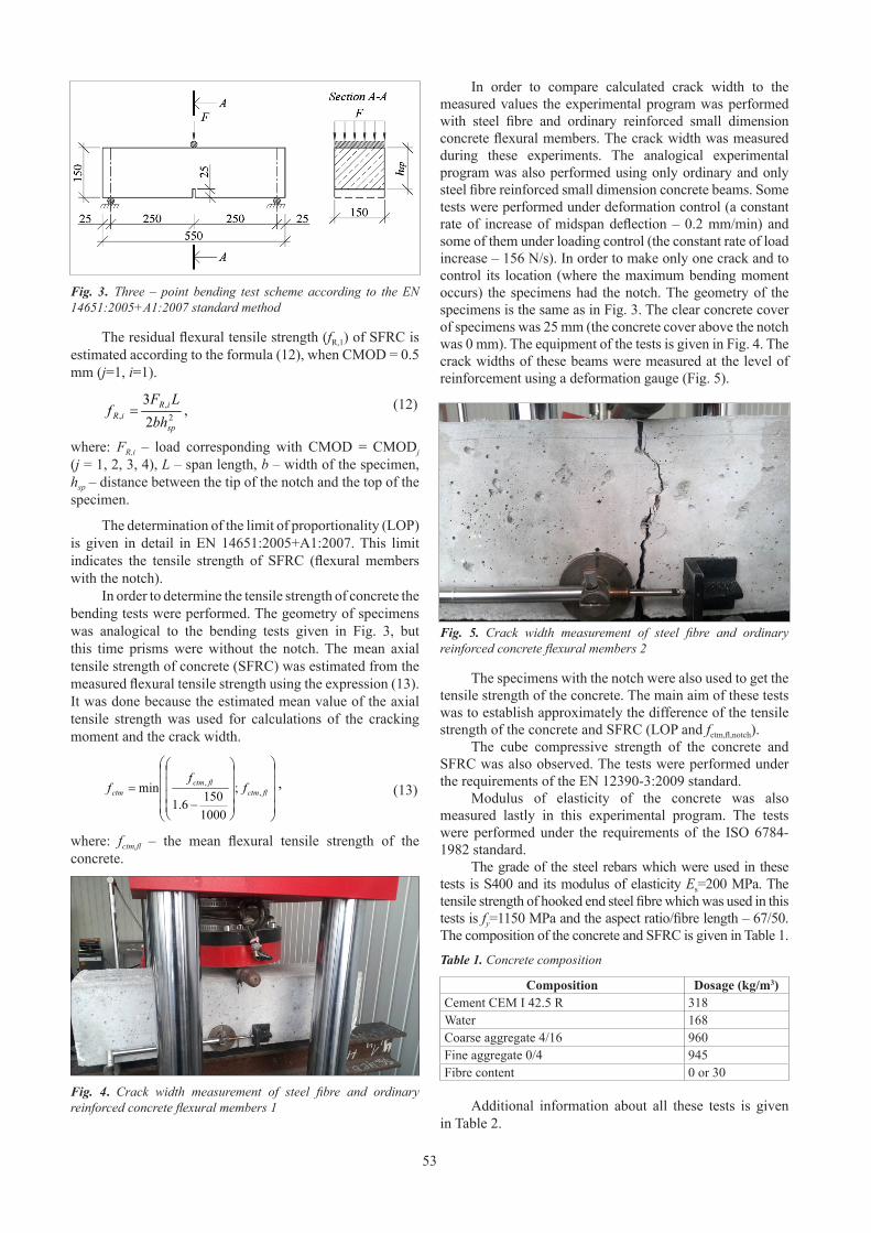
53
Fig. 3. Three – point bending test scheme according to the EN 14651:2005+A1:2007 standard method
The residual flexural tensile strength (fR,1) of SFRC is estimated according to the formula (12), when CMOD = 0.5 mm (j=1, i=1).
Fig. 3. Three – point bending test scheme according to the EN
14651:2005+A1:2007 standard method
The residual flexural tensile strength (fR,1
) of SFRC is
estimated according to the formula (12), when CMOD = 0.5
mm (j=1, i=1).
2
,
,
2
3
sp
iR
iR
bh
LF
f = , (12)
where: FR,i
– load corresponding with CMOD = CMODj (j =
1, 2, 3, 4), L – span length, b – width of the specimen, hsp
–
distance between the tip of the notch and the top of the
specimen.
The determination of the limit of proportionality (LOP)
is given in detail in EN 14651:2005+A1:2007. This limit
indicates the tensile strength of SFRC (flexural members
with the notch).
In order to determine the tensile strength of concrete
the bending tests were performed. The geometry of
specimens was analogical to the bending tests given in Fig.
3, but this time prisms were without the notch. The mean
axial tensile strength of concrete (SFRC) was estimated
from the measured flexural tensile strength using the
expression (13). It was done because the estimated mean
value of the axial tensile strength was used for calculations
of the cracking moment and the crack width.
⎟
⎟
⎟
⎟
⎠
⎞
⎜
⎜
⎜
⎜
⎝
⎛
⎟
⎟
⎟
⎟
⎠
⎞
⎜
⎜
⎜
⎜
⎝
⎛
−
=flctm
flctm
ctmf
f
f,
,
;
1000
150
6.1
min, (13)
where: fctm,fl
– the mean flexural tensile strength of the
concrete.
Fig. 4. Crack width measurement of steel fibre and ordinary
reinforced concrete flexural members 1
In order to compare calculated crack width to the
measured values the experimental program was performed
with steel fibre and ordinary reinforced small dimension
concrete flexural members. The crack width was measured
during these experiments. The analogical experimental
program was also performed using only ordinary and only
steel fibre reinforced small dimension concrete beams.
Some tests were performed under deformation control (a
constant rate of increase of midspan deflection – 0.2
mm/min) and some of them under loading control (the
constant rate of load increase – 156 N/s). In order to make
only one crack and to control its location (where the
maximum bending moment occurs) the specimens had the
notch. The geometry of the specimens is the same as in Fig.
3. The clear concrete cover of specimens was 25 mm (the
concrete cover above the notch was 0 mm). The equipment
of the tests is given in Fig. 4. The crack widths of these
beams were measured at the level of reinforcement using a
deformation gauge (Fig. 5).
Fig. 5. Crack width measurement of steel fibre and ordinary
reinforced concrete flexural members 2
The specimens with the notch were also used to get the
tensile strength of the concrete. The main aim of these tests
was to establish approximately the difference of the tensile
strength of the concrete and SFRC (LOP and fctm,fl,notch
).
The cube compressive strength of the concrete and
SFRC was also observed. The tests were performed under
the requirements of the EN 12390-3:2009 standard.
Modulus of elasticity of the concrete was also
measured lastly in this experimental program. The tests
were performed under the requirements of the ISO 6784-
1982 standard.
The grade of the steel rebars which were used in these
tests is S400 and its modulus of elasticity Es=200 MPa. The
tensile strength of hooked end steel fibre which was used in
this tests is fy=1150 MPa and the aspect ratio/fibre length –
67/50. The composition of the concrete and SFRC is given
in Table 1.
Table 1. Concrete composition
Composition Dosage (kg/m3
)
Cement CEM I 42.5 R 318
Water 168
Coarse aggregate 4/16 960
Fine aggregate 0/4 945
Fibre content 0 or 30
Additional information about all these tests is given in
Table 2.
(12)
where: FR,i – load corresponding with CMOD = CMODj (j = 1, 2, 3, 4), L – span length, b – width of the specimen, hsp – distance between the tip of the notch and the top of the specimen.
The determination of the limit of proportionality (LOP) is given in detail in EN 14651:2005+A1:2007. This limit indicates the tensile strength of SFRC (flexural members with the notch).
In order to determine the tensile strength of concrete the bending tests were performed. The geometry of specimens was analogical to the bending tests given in Fig. 3, but this time prisms were without the notch. The mean axial tensile strength of concrete (SFRC) was estimated from the measured flexural tensile strength using the expression (13). It was done because the estimated mean value of the axial tensile strength was used for calculations of the cracking moment and the crack width.
Fig. 3. Three – point bending test scheme according to the EN
14651:2005+A1:2007 standard method
The residual flexural tensile strength (fR,1
) of SFRC is
estimated according to the formula (12), when CMOD = 0.5
mm (j=1, i=1).
2
,
,
2
3
sp
iR
iR
bh
LF
f = , (12)
where: FR,i
– load corresponding with CMOD = CMODj (j =
1, 2, 3, 4), L – span length, b – width of the specimen, hsp
–
distance between the tip of the notch and the top of the
specimen.
The determination of the limit of proportionality (LOP)
is given in detail in EN 14651:2005+A1:2007. This limit
indicates the tensile strength of SFRC (flexural members
with the notch).
In order to determine the tensile strength of concrete
the bending tests were performed. The geometry of
specimens was analogical to the bending tests given in Fig.
3, but this time prisms were without the notch. The mean
axial tensile strength of concrete (SFRC) was estimated
from the measured flexural tensile strength using the
expression (13). It was done because the estimated mean
value of the axial tensile strength was used for calculations
of the cracking moment and the crack width.
⎟
⎟
⎟
⎟
⎠
⎞
⎜
⎜
⎜
⎜
⎝
⎛
⎟
⎟
⎟
⎟
⎠
⎞
⎜
⎜
⎜
⎜
⎝
⎛
−
=flctm
flctm
ctmf
f
f,
,
;
1000
150
6.1
min, (13)
where: fctm,fl
– the mean flexural tensile strength of the
concrete.
Fig. 4. Crack width measurement of steel fibre and ordinary
reinforced concrete flexural members 1
In order to compare calculated crack width to the
measured values the experimental program was performed
with steel fibre and ordinary reinforced small dimension
concrete flexural members. The crack width was measured
during these experiments. The analogical experimental
program was also performed using only ordinary and only
steel fibre reinforced small dimension concrete beams.
Some tests were performed under deformation control (a
constant rate of increase of midspan deflection – 0.2
mm/min) and some of them under loading control (the
constant rate of load increase – 156 N/s). In order to make
only one crack and to control its location (where the
maximum bending moment occurs) the specimens had the
notch. The geometry of the specimens is the same as in Fig.
3. The clear concrete cover of specimens was 25 mm (the
concrete cover above the notch was 0 mm). The equipment
of the tests is given in Fig. 4. The crack widths of these
beams were measured at the level of reinforcement using a
deformation gauge (Fig. 5).
Fig. 5. Crack width measurement of steel fibre and ordinary
reinforced concrete flexural members 2
The specimens with the notch were also used to get the
tensile strength of the concrete. The main aim of these tests
was to establish approximately the difference of the tensile
strength of the concrete and SFRC (LOP and fctm,fl,notch
).
The cube compressive strength of the concrete and
SFRC was also observed. The tests were performed under
the requirements of the EN 12390-3:2009 standard.
Modulus of elasticity of the concrete was also
measured lastly in this experimental program. The tests
were performed under the requirements of the ISO 6784-
1982 standard.
The grade of the steel rebars which were used in these
tests is S400 and its modulus of elasticity Es=200 MPa. The
tensile strength of hooked end steel fibre which was used in
this tests is fy=1150 MPa and the aspect ratio/fibre length –
67/50. The composition of the concrete and SFRC is given
in Table 1.
Table 1. Concrete composition
Composition Dosage (kg/m3
)
Cement CEM I 42.5 R 318
Water 168
Coarse aggregate 4/16 960
Fine aggregate 0/4 945
Fibre content 0 or 30
Additional information about all these tests is given in
Table 2.
(13)
where: fctm,fl – the mean flexural tensile strength of the concrete.
Fig. 4. Crack width measurement of steel fibre and ordinary reinforced concrete flexural members 1
In order to compare calculated crack width to the measured values the experimental program was performed with steel fibre and ordinary reinforced small dimension concrete flexural members. The crack width was measured during these experiments. The analogical experimental program was also performed using only ordinary and only steel fibre reinforced small dimension concrete beams. Some tests were performed under deformation control (a constant rate of increase of midspan deflection – 0.2 mm/min) and some of them under loading control (the constant rate of load increase – 156 N/s). In order to make only one crack and to control its location (where the maximum bending moment occurs) the specimens had the notch. The geometry of the specimens is the same as in Fig. 3. The clear concrete cover of specimens was 25 mm (the concrete cover above the notch was 0 mm). The equipment of the tests is given in Fig. 4. The crack widths of these beams were measured at the level of reinforcement using a deformation gauge (Fig. 5).
Fig. 5. Crack width measurement of steel fibre and ordinary reinforced concrete flexural members 2
The specimens with the notch were also used to get the tensile strength of the concrete. The main aim of these tests was to establish approximately the difference of the tensile strength of the concrete and SFRC (LOP and fctm,fl,notch).
The cube compressive strength of the concrete and SFRC was also observed. The tests were performed under the requirements of the EN 12390-3:2009 standard.
Modulus of elasticity of the concrete was also measured lastly in this experimental program. The tests were performed under the requirements of the ISO 6784-1982 standard.
The grade of the steel rebars which were used in these tests is S400 and its modulus of elasticity Es=200 MPa. The tensile strength of hooked end steel fibre which was used in this tests is fy=1150 MPa and the aspect ratio/fibre length – 67/50. The composition of the concrete and SFRC is given in Table 1.
Table 1. Concrete composition
Composition Dosage (kg/m3)Cement CEM I 42.5 R 318Water 168Coarse aggregate 4/16 960Fine aggregate 0/4 945Fibre content 0 or 30
Additional information about all these tests is given in Table 2.

54
3. Results
3.1 Experimental resultsTests results are presented in Table 3 and in Fig. 6 –
Fig. 8.
Table 3. Estimated properties of concrete and SFRC
Test No. Fibre content, kg/m3
Parameter notation Value, MPa
1 30 fRm,1 3.071 30 LOP 4.242 – fctm,fl 4.465 – fctm,fl,notch 3.659 – fcm.cub 47.0410 30 fcm,fb.cub 49.6611 30 Ecm 32988
It can be seen from the Table 3 that the case of the deflection softening is obtained when the fibre content is 30 kg/m3, because the mean residual tensile strength (fRm,1) is less than the limit of the proportionality (LOP). In comparison of the results of the tests No. 2 and No. 5 it is observed that the mean flexural tensile strength (fctm,fl) of the specimens with the notch is less. The earlier fracture of the specimens with the notch was obtained due to stress concentrations. The difference of the results could be influenced slightly because of the different loading control. Considering to this fact we can state that flexural tensile strength of SFRC is higher than the limit of proportionality (LOP).
In analogical comparison of the results of the tests No. 1 and No. 5 (LOP with fctm,fl,notch), it can be seen that the steel fibre increased significantly the average flexural fracture stress. The number of the specimens with the steel fibre was 12 and the minimum value of LOP was obtained 3.82 MPa. However, only 3 specimens without the steel fibre were tested and the minimum fracture stress value reached 3.59 MPa. Therefore, it can be seen from Table 3 and from above mentioned results that the flexural tensile strength is influenced strongly of the distribution of the steel fibre.
Due to the small content of the steel fibre and the sufficiently long fibres the compressive strength of the concrete was changed marginally. The similar results have been obtained by L. Vandewalle (Vandewalle, 2007).
The residual tensile strength fR,1 is determined when CMOD=0.5 mm. The stress – CMOD curves of SFRC is obtained experimentally and is presented in Fig 6. Here we can see that the distribution of the fibres influences strongly on the residual flexural tensile strength and the scatter of the results is very high. The difference between minimum and maximum values of fR,1 almost reaches the average value (ΔfR,1 = 2.61 MPa < fRm,1 = 3.07 MPa), and the coefficient of variation is equal to 0.234. The analogically high scatter of the results has been observed by other researchers’ who have performed the experimental research by the same method (Parmentier et. al., 2008; Vandewalle et. al., 2008).
Fig. 6. Residual flexural tensile strength – CMOD curves (Test No.1)
Fig. 7 presents F-w curves of 6 specimens from No. 3 and No. 4 tests. It can be seen, that the 30 kg/m3 content of steel fibre not only increased the strength of the member, but also reduced significantly the crack width at the same loading level. For example, when bending moment was equal to 17 kNm, then the crack width of the members without the steel fibre reached 4.8 mm, and the crack of the members with the steel fibre – 0.065 mm. However, the load difference from the moment when the crack opens until the fracture of the member is not high for the small cross section members and for the members with the small reinforcement ratio. Whereas when the steel fibre was used this difference was higher more than two times.
Table 2. Information of tests (45 specimens)
Test No.
Description of specimens
Geometry of specimens, mm
Number of specimens
Fibre content, kg/m3
Rebars LoadingMeasured
parameter or relation
1 Prisms with notch 600x150x150 12 30 – under deformation control F–CMOD, fRm,1, LOP2 Prisms without notch 600x150x150 3 – – under deformation control fctm,fl
3 Beams with notch 600x150x150 3 – 1ø6 S400 under deformation control F-w (relation)4 Beams with notch 600x150x150 3 30 1ø6 S400 under deformation control F-w (relation)5 Prisms with notch 600x150x150 2 – – under force control fctm,fl,notch
6 Beams with notch 600x150x150 2 30 – under force control F-w (relation)7 Beams with notch 600x150x150 2 – 1ø6 S400 under force control F-w (relation)8 Beams with notch 600x150x150 2 30 1ø6 S400 under force control F-w (relation)9 Cubes 100x100x100 4 – – under force control fcm.cub
10 Cubes 100x100x100 9 30 – under force control fcm,fb.cub
11 Prisms 300x100x100 3 – – under force control Ecm
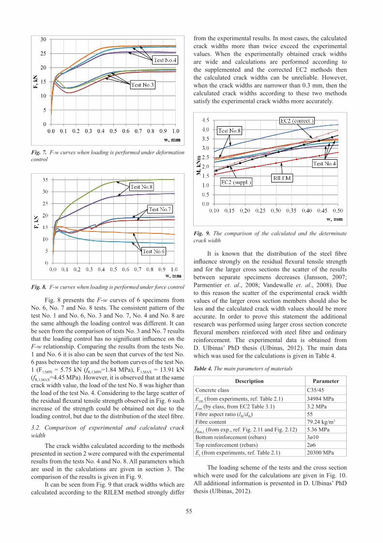
55
Fig. 7. F-w curves when loading is performed under deformation control
Fig. 8. F-w curves when loading is performed under force control
Fig. 8 presents the F-w curves of 6 specimens from No. 6, No. 7 and No. 8 tests. The consistent pattern of the test No. 1 and No. 6, No. 3 and No. 7, No. 4 and No. 8 are the same although the loading control was different. It can be seen from the comparison of tests No. 3 and No. 7 results that the loading control has no significant influence on the F-w relationship. Comparing the results from the tests No. 1 and No. 6 it is also can be seen that curves of the test No. 6 pass between the top and the bottom curves of the test No. 1 (F1,MIN = 5.75 kN (fR,1,MIN=1.84 MPa), F1,MAX = 13.91 kN (fR,1,MAX=4.45 MPa). However, it is observed that at the same crack width value, the load of the test No. 8 was higher than the load of the test No. 4. Considering to the large scatter of the residual flexural tensile strength observed in Fig. 6 such increase of the strength could be obtained not due to the loading control, but due to the distribution of the steel fibre.
3.2. Comparison of experimental and calculated crack width
The crack widths calculated according to the methods presented in section 2 were compared with the experimental results from the tests No. 4 and No. 8. All parameters which are used in the calculations are given in section 3. The comparison of the results is given in Fig. 9.
It can be seen from Fig. 9 that crack widths which are calculated according to the RILEM method strongly differ
from the experimental results. In most cases, the calculated crack widths more than twice exceed the experimental values. When the experimentally obtained crack widths are wide and calculations are performed according to the supplemented and the corrected EC2 methods then the calculated crack widths can be unreliable. However, when the crack widths are narrower than 0.3 mm, then the calculated crack widths according to these two methods satisfy the experimental crack widths more accurately.
Fig. 9. The comparison of the calculated and the determinate crack width
It is known that the distribution of the steel fibre influence strongly on the residual flexural tensile strength and for the larger cross sections the scatter of the results between separate specimens decreases (Jansson, 2007; Parmentier et. al., 2008; Vandewalle et. al., 2008). Due to this reason the scatter of the experimental crack width values of the larger cross section members should also be less and the calculated crack width values should be more accurate. In order to prove this statement the additional research was performed using larger cross section concrete flexural members reinforced with steel fibre and ordinary reinforcement. The experimental data is obtained from D. Ulbinas’ PhD thesis (Ulbinas, 2012). The main data which was used for the calculations is given in Table 4.
Table 4. The main parameters of materials
Description ParameterConcrete class C35/45Ecm (from experiments, ref. Table 2.1) 34984 MPafctm (by class, from EC2 Table 3.1) 3.2 MPaFibre aspect ratio (lfb/dfb) 55Fibre content 79.24 kg/m3
fRm,1 (from exp., ref. Fig. 2.11 and Fig. 2.12) 5.36 MPaBottom reinforcement (rebars) 3ø10Top reinforcement (rebars) 2ø6Es (from experiments, ref. Table 2.1) 20300 MPa
The loading scheme of the tests and the cross section which were used for the calculations are given in Fig. 10. All additional information is presented in D. Ulbinas’ PhD thesis (Ulbinas, 2012).
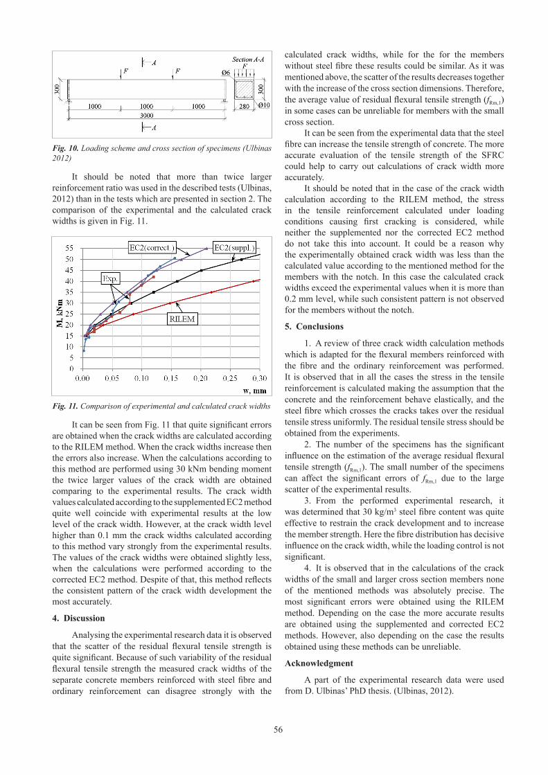
56
Fig. 10. Loading scheme and cross section of specimens (Ulbinas 2012)
It should be noted that more than twice larger reinforcement ratio was used in the described tests (Ulbinas, 2012) than in the tests which are presented in section 2. The comparison of the experimental and the calculated crack widths is given in Fig. 11.
Fig. 11. Comparison of experimental and calculated crack widths
It can be seen from Fig. 11 that quite significant errors are obtained when the crack widths are calculated according to the RILEM method. When the crack widths increase then the errors also increase. When the calculations according to this method are performed using 30 kNm bending moment the twice larger values of the crack width are obtained comparing to the experimental results. The crack width values calculated according to the supplemented EC2 method quite well coincide with experimental results at the low level of the crack width. However, at the crack width level higher than 0.1 mm the crack widths calculated according to this method vary strongly from the experimental results. The values of the crack widths were obtained slightly less, when the calculations were performed according to the corrected EC2 method. Despite of that, this method reflects the consistent pattern of the crack width development the most accurately.
4. Discussion
Analysing the experimental research data it is observed that the scatter of the residual flexural tensile strength is quite significant. Because of such variability of the residual flexural tensile strength the measured crack widths of the separate concrete members reinforced with steel fibre and ordinary reinforcement can disagree strongly with the
calculated crack widths, while for the for the members without steel fibre these results could be similar. As it was mentioned above, the scatter of the results decreases together with the increase of the cross section dimensions. Therefore, the average value of residual flexural tensile strength (fRm,1) in some cases can be unreliable for members with the small cross section.
It can be seen from the experimental data that the steel fibre can increase the tensile strength of concrete. The more accurate evaluation of the tensile strength of the SFRC could help to carry out calculations of crack width more accurately.
It should be noted that in the case of the crack width calculation according to the RILEM method, the stress in the tensile reinforcement calculated under loading conditions causing first cracking is considered, while neither the supplemented nor the corrected EC2 method do not take this into account. It could be a reason why the experimentally obtained crack width was less than the calculated value according to the mentioned method for the members with the notch. In this case the calculated crack widths exceed the experimental values when it is more than 0.2 mm level, while such consistent pattern is not observed for the members without the notch.
5. Conclusions
1. A review of three crack width calculation methods which is adapted for the flexural members reinforced with the fibre and the ordinary reinforcement was performed. It is observed that in all the cases the stress in the tensile reinforcement is calculated making the assumption that the concrete and the reinforcement behave elastically, and the steel fibre which crosses the cracks takes over the residual tensile stress uniformly. The residual tensile stress should be obtained from the experiments.
2. The number of the specimens has the significant influence on the estimation of the average residual flexural tensile strength (fRm,1). The small number of the specimens can affect the significant errors of fRm,1 due to the large scatter of the experimental results.
3. From the performed experimental research, it was determined that 30 kg/m3 steel fibre content was quite effective to restrain the crack development and to increase the member strength. Here the fibre distribution has decisive influence on the crack width, while the loading control is not significant.
4. It is observed that in the calculations of the crack widths of the small and larger cross section members none of the mentioned methods was absolutely precise. The most significant errors were obtained using the RILEM method. Depending on the case the more accurate results are obtained using the supplemented and corrected EC2 methods. However, also depending on the case the results obtained using these methods can be unreliable.
Acknowledgment
A part of the experimental research data were used from D. Ulbinas’ PhD thesis. (Ulbinas, 2012).
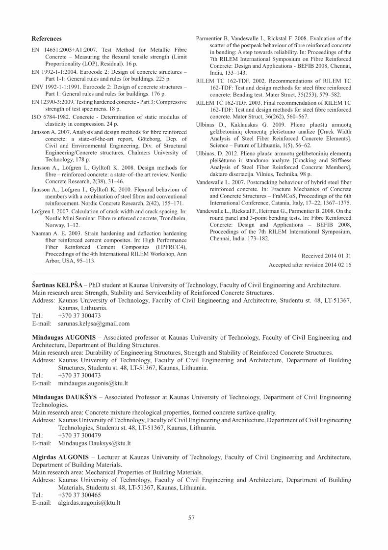
57
References
EN 14651:2005+A1:2007. Test Method for Metallic Fibre Concrete – Measuring the flexural tensile strength (Limit Proportionality (LOP), Residual). 16 p.
EN 1992-1-1:2004. Eurocode 2: Design of concrete structures – Part 1-1: General rules and rules for buildings. 225 p.
ENV 1992-1-1:1991. Eurocode 2: Design of concrete structures – Part 1: General rules and rules for buildings. 176 p.
EN 12390-3:2009. Testing hardened concrete - Part 3: Compressive strength of test specimens. 18 p.
ISO 6784-1982. Concrete - Determination of static modulus of elasticity in compression. 24 p.
Jansson A. 2007. Analysis and design methods for fibre reinforced concrete: a state-of-the-art report, Göteborg, Dep. of Civil and Environmental Engineering, Div. of Structural Engineering/Concrete structures, Chalmers University of Technology, 178 p.
Jansson A., Löfgren I., Gylltoft K. 2008. Design methods for fibre – reinforced concrete: a state–of–the art review. Nordic Concrete Research, 2(38), 31–46.
Jansson A., Löfgren I., Gylltoft K. 2010. Flexural behaviour of members with a combination of steel fibres and conventional reinforcement. Nordic Concrete Research, 2(42), 155–171.
Löfgren I. 2007. Calculation of crack width and crack spacing. In: Nordic Mini Seminar: Fibre reinforced concrete, Trondheim, Norway, 1–12.
Naaman A. E. 2003. Strain hardening and deflection hardening fiber reinforced cement composites. In: High Performance Fiber Reinforced Cement Composites (HPFRCC4), Proceedings of the 4th International RILEM Workshop, Ann Arbor, USA, 95–113.
Parmentier B, Vandewalle L, Rickstal F. 2008. Evaluation of the scatter of the postpeak behaviour of fibre reinforced concrete in bending: A step towards reliability. In: Proceedings of the 7th RILEM International Symposium on Fibre Reinforced Concrete: Design and Applications - BEFIB 2008, Chennai, India, 133–143.
RILEM TC 162-TDF. 2002. Recommendations of RILEM TC 162-TDF: Test and design methods for steel fibre reinforced concrete: Bending test. Mater Struct, 35(253), 579–582.
RILEM TC 162-TDF. 2003. Final recommendation of RILEM TC 162-TDF: Test and design methods for steel fibre reinforced concrete. Mater Struct, 36(262), 560–567.
Ulbinas D., Kaklauskas G. 2009. Plieno pluoštu armuotų gelžbetoninių elementų pleišėtumo analizė [Crack Width Analysis of Steel Fiber Reinforced Concrete Elements]. Science – Future of Lithuania, 1(5), 56–62.
Ulbinas, D. 2012. Plieno plaušu armuotų gelžbetoninių elementų pleišėtumo ir standumo analyze [Cracking and Stiffness Analysis of Steel Fiber Reinforced Concrete Members], daktaro disertacija. Vilnius, Technika, 98 p.
Vandewalle L. 2007. Postcracking behaviour of hybrid steel fiber reinforced concrete. In: Fracture Mechanics of Concrete and Concrete Structures – FraMCoS, Proceedings of the 6th International Conference, Catania, Italy, 17–22, 1367–1375.
Vandewalle L., Rickstal F., Heirman G., Parmentier B. 2008. On the round panel and 3-point bending tests. In: Fibre Reinforced Concrete: Design and Applications – BEFIB 2008, Proceedings of the 7th RILEM International Symposium, Chennai, India. 173–182.
Received 2014 01 31 Accepted after revision 2014 02 16
Šarūnas KELPŠA – PhD student at Kaunas University of Technology, Faculty of Civil Engineering and Architecture.Main research area: Strength, Stability and Serviceability of Reinforced Concrete Structures. Address: Kaunas University of Technology, Faculty of Civil Engineering and Architecture, Studentu st. 48, LT-51367,
Kaunas, Lithuania.Tel.: +370 37 300473E-mail: [email protected]
Mindaugas AUGONIS – Associated professor at Kaunas University of Technology, Faculty of Civil Engineering and Architecture, Department of Building Structures.Main research area: Durability of Engineering Structures, Strength and Stability of Reinforced Concrete Structures. Address: Kaunas University of Technology, Faculty of Civil Engineering and Architecture, Department of Building
Structures, Studentu st. 48, LT-51367, Kaunas, Lithuania.Tel.: +370 37 300473E-mail: [email protected]
Mindaugas DAUKŠYS – Associated Professor at Kaunas University of Technology, Department of Civil Engineering Technologies.Main research area: Concrete mixture rheological properties, formed concrete surface quality.Address: Kaunas University of Technology, Faculty of Civil Engineering and Architecture, Department of Civil Engineering
Technologies, Studentu st. 48, LT-51367, Kaunas, Lithuania.Tel.: +370 37 300479E-mail: [email protected]
Algirdas AUGONIS – Lecturer at Kaunas University of Technology, Faculty of Civil Engineering and Architecture, Department of Building Materials.Main research area: Mechanical Properties of Building Materials.Address: Kaunas University of Technology, Faculty of Civil Engineering and Architecture, Department of Building
Materials, Studentu st. 48, LT-51367, Kaunas, Lithuania.Tel.: +370 37 300465E-mail: [email protected]