Shear crack width assessment in concrete structures by 2D ...

134 TRANSPORTATION RESEARCH RECORD 1449
Factors Affecting Crack Width of Continuously Reinforced Concrete Pavement
YOUNG-CHAN SUH AND B. FRANK McCULLOUGH
Crack width is an important factor affecting the behavior and performance of continuously reinforced concrete pavement (CRCP). Wide cracks can lead to various pavement distresses, including spalling, punchouts, and steel rupture. Various factors affecting CRCP crack width were evaluated on the basis of the width measurements of 208 transverse cracks randomly selected from a series of experimental test sections constructed in Houston, Tex. The crack widths were measured at various times and slab temperatures by using a microscope with a graduated eyepiece. It was found from a statistical analysis of the collected data that the factors that significantly affect crack width are construction season, coarse aggregate type, amount of steel, and time of crack occurrence. Thus, hot weather placement produced much wider cracks than cool weather placement. The use of siliceous river gravel resulted in cracks wider than those associated with the use of limestone, and the difference was larger at lower temperatures. The greater the amount of longitudinal steel, the narrower the crack width. Cracks occurring during the first 3 days of construction were significantly wider than those that occurred later. Finally, the effect of crack spacing on crack width was found to be insignificant.
Crack width is an important factor affecting the behavior and performance of continuously reinforced concrete pavement (CRCP). For effective performance crack width should be narrow enough to provide sufficient aggregate interlocking and to avoid infiltration of appreciable amounts of water through the crack.
Excessive crack openings can lead to the loss of load transfer, causing excessive flexing of the concrete slab under traffic (with the resultant spalling of the concrete). They can also lead to punchouts, steel rupture, the infiltration of incompressible material (causing spalling and blowups), and water seepage that can reduce roadbed support and that can cause rusting of the steel (1). A maximum allowable crack width of 0.04 in. was suggested by AASHTO (2) on the basis of the consideration of spalling and water penetration.
Crack width varies with temperature; cracks are wider in cold weather when the concrete slab has contracted than in hot weather when the individual concrete slabs have expanded. Crack width also changes with age. Drying shrinkage (which occurs after the initial crack formation) and incompressible foreign material entering the crack both contribute to the increase in crack width (3,4). The rate of increase, however, decreases with time (1). Many literature sources (1,5,6) have indicated that the crack width varies with the depth of the crack, being greatest at the surface and progressively smaller with increasing depth. It is a well-accepted fact that the crack width is a function of the amount of
Y. C. Suh, Korea Institute of Construction Technology, Seoul, Republic of Korea. B. F. McCullough, Center for Transportation Research, University of Texas, Austin, Tex. 78712.
longitudinal steel, in which the greater the amount of longitudinal steel, the smaller the crack width (1,7). This is true because crack width is a function of steel stress and the effectiveness of the bond between the concrete and steel near the crack. In this paper various design and construction factors affecting crack width are evaluated on the basis of field measurements of crack widths taken from a series of experimental test sections.
EXPERIMENTAL TEST SECTIONS
The experiment included CRCP test projects constructed at four locations in Houston (8). 'They were placed during two different seasons (summer and winter). For convenience the following abbreviations for the projects will be used in this paper:
SH6-summer: These test sections were placed on State Highway 6 in the summer (June 1989).
BW8-winter: These test sections were placed on Beltway 8 in the winter (November 1989).
SH6-winter: These test sections were placed on State Highway 6 in the winter (January 1990).
IH45-winter: These test sections were placed on Interstate Highway 45 in the winter (January 1990).
With each project, 1,840 ft of CRCP was placed; one-half of the length (920 ft) used siliceous river gravel (SRG) and the other half used limestone (LS) as the coarse aggregate. Each of these lengths was subdivided into four test sections so that each section was 230 ft long (8).
One of the four sections for each coarse aggregate type used the same quantity of longitudinal steel specified in the Texas design standard (8), CRCP(B)-89B (hereafter termed medium steel). Two other test sections used about 0.1 percent higher quantity and lower quantity, respectively, of longitudinal steel than the medium steel (hereafter termed high steel and low steel, respectively). These three test sections used a 3/4-in.-diameter bar (No. 6 bar). The fourth test section used medium steel with a larger-size bar (a 7/8-in.-diameter or No. 7 bar) for investigating the interactive effect of bond area and concrete volume ratio.
EXPERIMENTS
A total of 208 transverse cracks was selected: sixty-four cracks (8 cracks from each of eight sections) were selected from SH6-summer, and 48 cracks (6 cracks from each of eight sections) were

Suh and McCullough
selected from each of the BW8-winter, SH6-winter, and IH45-winter projects. The cracks were randomly selected within a section by using a random number table (9).
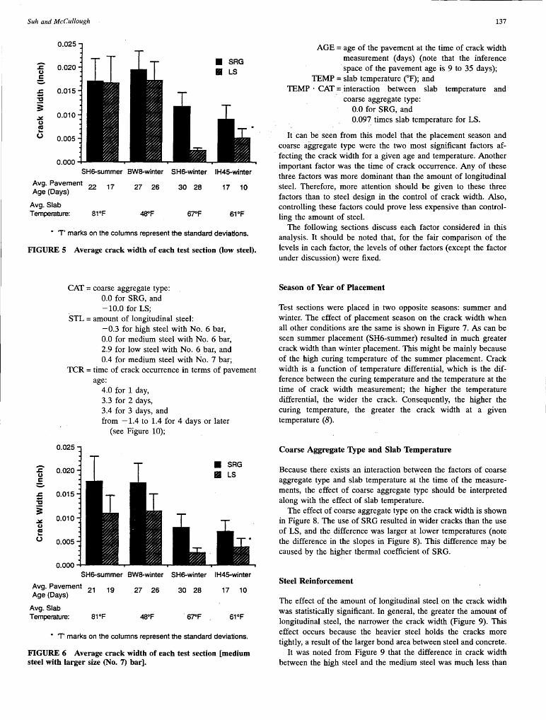
The crack widths were measured at various times and slab temperatures by using a microscope with a graduated eyepiece (Figure 1 ). The microscope contained a vernier scale and was capable of measuring to the closest 0.001 in. Measurements were performed by one operator so as to reduce measurement error caused by operator variance. Slab temperatures were measured at three positions along the thickness of the slab: top (1 in. from the surface), middle (center of the slab), and bottom (1 in. from the bottom).
The temperatures at these three positions were correlated with the crack width, which was measured under various time and temperature conditions, to select the position at which the temperatures most nearly identified with the crack width. The typical plots of correlations are given in Figure 2. These plots indicate that the slab temperatures at the top give the best correlation with the crack widths. Accordingly, the slab temperatures at the top were used to represent the slab temperature in this crack width study. Summarized in Table 1 are the time of crack width measurements and the corresponding slab temperature.
It should be noted that the crack widths were measured near the center of the traffic lane. At first, three locations along the crack, near both ends and at the center of the traffic lane, were measured and were averaged to represent the width of the crack. But because there was no significant difference between the average of the crack widths measured at three locations and the crack width measured at the center, the crack width at the center location was therefore used.
The averages and standard deviations of the crack widths collected from the test sections are shown in Figures 3 through 6 for the four different steel reinforcement designs. The T marks on the columns in the figures represent the standard deviations of the crack widths. It is apparent that a difference in average crack width exists between the pavements with different types of coarse aggregate; sections with SRG showed greater crack widths than those with LS in all the cases except for the high steel sections placed on State Highway 6 in the summer (Figure 3), in which the order is opposite but the difference is negligible, considering the standard deviation.
FIGURE 1 Crack width measurement with a measuring microscope.
135
~ 0.025
0 SAG u e. 0.020 • LS 0
~ 0
:c; O.Q15 0 0
i • • .:.:: 0.010 • • u ca ... (.) 0.005
40 45 50
(a) Slab Temperature-Top (oF)
~ 0.025 u e. 0.020 0
~ 0
:c; O.Q15 0 0 i ' 0
.:.:: • • u 0.010 • ca ... (.) 0.005
40 45 50
(b) Slab Temperature-Middle (oF)
~ 0.025
CJ
g 0.020 0 0
~ :c; O.Q15 0 0
i o• • 0.010 • • .:.:: • CJ
ca ... (.) 0.005
40 45 so (c) Slab Temperature-Bottom {°F)
FIGURE 2 Correlation of slab temperature at various positions with corresponding crack width.
FACTORS AFFECTING CRACK WIDTH
0
•
55
55
55
Because the measurements of the crack widths were conducted at different conditions in terms of slab temperature and pavement age, it was difficult to extract additional information from Figures 3 through 6. To identify and evaluate the factors affecting the crack width, the crack width data were statistically analyzed by using the General Linear Model (GLM) procedure in the SAS.
The variables considered in that analysis included project (with two different seasons), coarse aggregate type, amount of longitudinal steel, time of crack occurrence, crack spacing, pavement age, and slab temperature. Some of the two-factor interactions were

136 TRANSPORTATION RESEARCH RECORD 1449
TABLE 1 Time of Crack Width Measurements and Corresponding Slab Temperature
SH6-summer 1st Date 6128189
Measurement Time 6:12AM Slabtemo. 73.3
2nd Date 6128189 Measurement Time 1:54 PM
Slab temp. 79.4
3rd Date 6129189 Measurement Time 1:28 PM
Slabtemo. 76.5 4th Date 716189
Measurement Time 6:30AM Slab temp. 76.1
5th Date 7/19/89 Measurement Time 3:05 PM
Slab temp. 96.3 Construction SAG sections 6116/89
Date LS sections 6119/89
also investigated in the analysis. They include crack spacingcoarse aggregate type, amount of steel-coarse aggregate type, and slab temperature-coarse aggregate type.
In theory there is a nonlinear relationship between pavement age and crack width that is mainly a result of the nonlinearities of drying shrinkage and creep. However, because the range of pavement ages at the time of crack width measurements represented a relatively short time period (9 to 35 days after construction), a linear relationship was assumed.
The GLM analysis indicated that the significant factors affecting crack width at the 0.05 level included project, coarse aggregate type, amount of longitudinal steel, time of crack occurrence, pavement age, slab temperature, and the interaction between slab temperature and coarse aggregate type. (They were significant even at the significance level of 0.0001.) Crack spacing and the inter-
0.025
• SAG 0.020
• LS
0.015
0.010
0.005
0.000 SH6-summer BW8-winter SH6-winter IH45-winter
Avg. Pavement 22 18
Age (Days)
Avg. Slab Temperature: 81°F
27 26
48°F
30 28 17 10
67°F 61°F
• 'T' marks on the columns represent the standard deviations.
FIGURE 3 Average crack width of each test section (high steel).
TEST SECTION BW8-winter SHS-winter IH45-winter
12120/89 2/1/90 1/31/90
1:14 PM 10:42AM 9:00AM
54.4 65.8 58.2
12121/89 211/90 1/31/90
6:50 AM 3:50 PM 11:30 AM •. -42.7 ·. '. "64.2 61.3
12121/89 2/13190 1/31/90
9:50AM 12:00NOON 3:05 PM
44.2 69.9 62.2 12121/89 2/13190 2/14/90 12:50 PM 2:00 PM 4:30 PM
47.6 73.4 70.2 12121/89 2/14190 2/15/90 2:00 PM 7:55AM 8:57 AM
48.8 63.5 65.7 11124189 1/10-11/90 1114190 11125189 1111-12/90 1/21190
actions of crack spacing-coarse aggregate type and amount of steel-coarse aggregate type were not significant at the 0.05 level. The R2 value of the model was 0.82, indicating a good fit. The model can_ be expressed as:
CW= 34.1 + PROJ +CAT+ STL + TCR + 0.15 ·AGE
- 0.50 · TEMP + TEMP · CAT
where
CW = crack width in 0.001 in.; PROJ = project and season of placement:
14.9 for SH6-summer, 1.5 for BW8-winter, 0.0 for SH6-winter, and 0. 7 for IH45-winter;
0.025
0.020
0.015
0.010
0.005
0.000
• q~G • LS
SH6-summer BW8-winter SH6-winter IH45-winter
Avg. Pavement 17 Age (Days)
Avg. Slab Temperature: 81°F
14 27 26
48"F
30 28. 17 10
67°F 61°F
• T' marks on the columns represent the standard deviations.
FIGURE 4 Average crack width of each test section (medium steel).
Suh and McCullough
0.025
0.020
0.015
0.010
0.005
0.000 SH6-summer BWS-winter SH6-winter IH45-winter
Avg. Pavement 22 17 Age (Days)
27 26 30 28 17 10
Avg. Slab Temperature: 81°F 48°F 67°F 61°F
* 'T' marks on the columns represent the standard deviations.
FIGURE 5 Average crack width of each test section Oow steel).
~ CJ ca ... (.)
CAT= coarse aggregate type: 0.0 for SRG, and -10.0 for LS;
STL = amount of longitudinal steel: -0.3 for high steel with No. 6 bar, 0.0 for medium steel with No. 6 bar, 2.9 for low steel with No. 6 bar, and 0.4 for medium steel with No. 7 bar;
TCR = time of crack occurrence in terms of pavement
0.025
0.020
0.015
0.010
0.005
0.000
age: 4.0 for 1 day, 3.3 for 2 days, 3.4 for 3 days, and from -1.4 to 1.4 for 4 days or later
(see Figure 10);
SH6-summer BWS-winter SH6-winter IH45-winter
Avg. Pavement 21 19 Age (Days)
27 26 30 28 17 10
Avg. Slab Temperature: 81°F 48°F 67°F 61°F
• 'T' marks on the columns represent the standard deviations.
FIGURE 6 Average crack width of each test section [medium steel with larger size (No. 7) bar].
137
AGE = age of the pavement at the time of crack width measurement (days) (note that the inference
-space of the pavement age is 9 to 35 days); TEMP = slab temperature (°F); and
TEMP · CAT =.interaction between slab temperature and coarse aggregate type:
0.0 for SRG, and 0.097 times slab temperature for LS.
It can be seen from this model that the placement season and coarse aggregate type were the two most significant factors affecting the crack width for a given age and temperature. Another important factor was the time of crack occurrence. Any of these three factors was more dominant than the amount of longitudinal steel. Therefore, more attention should be given to these three factors than to steel design in the control of crack width. Also, controlling these factors could prove less expensive than controlling the amount of steel.
The following sections discuss each factor considered in this analysis. It should be noted that, for the fair comparison of the levels in each factor, the levels of other factors (except the factor under discussion) were fixed.
Season of Year of Placement
Test sections were placed in two opposite seasons: summer and winter. The effect of placement season on the crack width when all other conditions are the same is shown in Figure 7. As can be seen summer placement (SH6-summer) resulted in much greater crack width than winter placement. This might be mainly because of the high curing temperature of the summer placement. Crack width is a function of temperature differential, which is the difference between the curing temperature and the temperature at the time of crack width measurement; the higher the temperature differential, the wider the crack. Consequently, the higher the curing temperature, the greater the crack width at a given temperature (8).
Coarse Aggregate Type and Slab Temperature
Because there exists an interaction between the factors of coarse aggregate type and slab temperature at the time of the measurements, the effect of coarse aggregate type should be interpreted along with the effect of slab temperature.
The effect of coarse aggregate type on the crack width is shown in Figure 8. The use of SRG resulted in wider cracks than the use of LS, and the difference was larger at lower temperatures (note the difference in the slopes in Figure 8). This difference may be caused by the higher thermal coefficient of SRG.
Steel Reinforcement
The effect of the amount of longitudinal steel on the crack width was statistically significant. In general, the greater the amount of longitudinal steel, the narrower the crack width (Figure 9). This effect occurs because the heavier steel holds the cracks more tightly, a result of the larger bond area between steel and concrete.
It was noted from Figure 9 that the difference in crack width between the high steel and the medium steel was much less than

138 TRANSPORTATION RESEARCH RECORD 1449
0.03
:c-u c 0.02 :::. .c ~· j ~ 0.01 u ca .. (,)
0.00 SH6-summer BW8-winter SH6-winter IH45-winter
Project
FIGURE 7 Effect of placement season on crack width.
Temperature (°F)
FIGURE 8 Effect of coarse aggregate type and slab temperature on crack width.
0.030
:2' (,) 0.028 g
.i= :c; 0.026 "i .>I! (,) 0.024 ca ...
(.)
0.022
0.020 Low Medium High
Amount of steel
100
FIGURE 9 Effect of longitudinal steel design on crack width.
that between the low steel and the medium steel, even though the differences in the amount of steel were about the same.
The effect of the size of the steel bar on crack width is also shown in Figure 9. The use of a larger bar (one having the same total amount of steel) resulted in slightly greater crack width; the use of No. 7 bars (7/8 in. in diameter) instead of No. 6 bars (3/4 in. in diameter) resulted in a slightly wider crack. This might be because of the smaller total bond area between steel and concrete of the larger-size bar (crack width is minimized by the bond between steel and concrete). It should be noted, however, that the increase in crack width by use of No. 7 bars instead of No. 6 bars was very small.
Time of Crack Occurrence
One of the unique findings of the study was the effect of the time of crack occurrence on the crack width. The cracks that occurred during the first 3 days after construction were significantly wider than those that occurred later (Figure 10).
0.028
:c 0.026 B u 11 B g .c 0.024
Iii a -a B Iii Iii i 0 .. 022 II Iii •• II
B .x Iii u Cll 0.020 .. CJ
0.018
0.016 0 3 6 9 12 15 18 21
Time of Crack Occurrence (Days after Construction)
FIGURE 10 Effect of time of crack occurrence on crack width.

Suh and McCullough 139
(1) Drying Shrinkage after Formation of Early-Age Crack
(2) Drying Shrinkage after Formation of Later-Age Crack
CD CD ca ~ c "C ~ en CD CD E c i= ~ CD c 0 c:
~ ~ CD a:
Pavement Age
FIGURE 11 Conceptual explanation of wider crack width of early-age cracks by difference in residual shrinkage.
As mentioned previously, drying shrinkage serves to explain the greater crack width of early-age cracks. Once a crack occurs its width increases as a result of the drying shrinkage of the concrete (3). It is believed that the increase in crack width is a function of the residual shrinkage (drying shrinkage after formation of the crack), and an early-age crack will have higher residual shrinkage than a later-age crack (Figure 11), consequently resulting in greater crack width.
Crack Spacing
It is generally believed that the greater the crack spacing, the greater the crack width. But the effect of crack spacing (slab length between the adjacent two cracks) on crack width was not statistically significant at the significance level of 0.05. Shown in Figure 12 is the plot of the crack width versus the crack spacing, indicating no significant correlation between crack spacing and
0.03 • ••• •
:c- • - • u 0.02 -.. , g ... • !'\ •• 9> •• • •••• s:. •• • • •
~ . --- . - • • . . .:: •• I\ i • •• • - • •• ... ·r' . -• • • ~ 0.01 •'::I:• •e u ....... • ca ·-. -- • • .. • •• -· • • • (.) • • • • • • •
·-~· ., •• - •
• • 0.00 0 10 20 30 40 50 60
Crack Spacing (feet)
FIGURE 12 Relationship between crack spacing and crack width, showing no significant correlatfon.
70
crack width. Each point on the graph has not standardized other variables (e.g., temperature). It should. also be recognized that the process of selecting a specific crack to study had an impact on the observations. Previous studies have always found a correlation between the average crack width for a given temperature and the average crack spacing.
SUMMARY OF FINDINGS
Various factors affecting crack width have been discussed on the basis of a statistical analysis conducted on the crack width data collected from the experimental test sections. Findings from the statistical analysis can be summarized as follows:
1. Hot weather placement resulted in much wider cracks than cool weather placement.
2. The use of SRG resulted in greater crack width than the use of LS, and the difference was larger at lower temperatures. This difference might be caused by the different thermal coefficients of the two coarse aggregate types used in the concretes .
3. The larger the amount of longitudinal steel, the narrower the crack width. However the difference in crack width between the high steel and the medium steel was less than that between the low steel and the medium steel.
4. Cracks occurring during the first 3 days of construction were significantly wider than those occurring later. Because early-age cracks are more prevalent with summer placement than with winter placement (8), special care should be taken during hot weather placement to reduce early-age cracks .
5. The effect of crack spacing on crack width was not significant owing to the nature of the data collection and analysis.
6. In the control of crack width, more attention should be given to the placement season, coarse aggregate type, and the time of crack occurrence (rather than to steel design). Controlling these factors could prove less expensive than controlling the amount of steel.

140
REFERENCES
1. Burke, J.E., and J. S. Dhamrait. A Twenty-Year Report on the Illinois Continuously Reinforced Concrete Pavements. In Highway Research Record 239, HRB, National Research Council, Washington, D.C., 1968.
2. Guide for Design of Pavement Structures, AASHTO, Washington, D.C., 1986.
3. Hughes, B. P., and T. Mahmood. An Investigation of Early Thermal Cracking in Concrete and the Recommendations in BS 8007. The Structural Engineer, Vol. 66, No. 4/16, Feb. 1988.
4. Russell, H. W., and J. D. Lindsay. Three-Year Performance Report on Experimental Continuously Reinforced Concrete Pavement in Illinois. Highway Research Board Proceedings, HRB, National Research Council, Washington, D.C., 1950.
5. Zollinger, D. G. Investigation of Punchout Distress of Continuously Reinforced Concrete Pavement. Ph.D. dissertation. University of Illinois, Urbana-Champaign, 1989.
TRANSPOR'IATION RESEARCH RECORD 1449
6. NCHRP Synthesis of Highway Practice 16: Continuously Reinforced Concrete Pavement. HRB, National Research Council, Washington, D.C., 1973.
7. Lindsay, J. D. A Ten-Year Report on the Illinois Continuously Reinforced Pavement. Bulletin 214, HRB, National Research Council, Washington, D.C., 1959.
8. Suh, Y. C. Early-Age Behavior of CRC Pavement and Calibration of the Failure Prediction Model in CRCP-7. Ph.D. dissertation. The University of Texas, Austin, May 1991.
9. Anderson, V. L., and R. A. McLean. Design of Experiments: A Realistic Approach. Marcel Dekker, Inc., New York.
Publication of this paper sponsored by Committee on Rigid Pavement Design.