ANALYSIS OF CONCRETE SLABS SUPPORTED ON...
21
MÉTODOS NUMÉRICOS EN INGENIERÍA R. Abascal, J. Domínguez y G. Bugeda (Eds.) © SEMNI, España 1999 1 ANALYSIS OF CONCRETE SLABS SUPPORTED ON SOIL Joaquim Barros • Departamento de Engenharia Civil • Escola de Engenharia da Universidade do Minho • Azurém, 4800 Guimarães, Portugal e-mail: [email protected] Palabras clave: Material non-linear analysis, steel fibre reinforced concrete, fracture energy, strain softening, strain stiffening, soil load bearing capacity Resumen: A numerical model for material non-linear analysis of concrete slabs supported on soil is described in this work. In this model, the cracked concrete is regarded as cracks with concrete between cracks. The behaviour of the concrete between cracks is simulated by the conventional theory of plasticity. The behaviour of the cracks is defined by their constitutive laws using the concrete fracture properties. Smeared multifixed and rotating crack models are available in the model. Concrete can be reinforced with sets of smeared bars of different materials and geometric properties, as well as with discrete steel fibres. A tension-stiffening model that takes into account the concrete fracture properties and the reinforcement characteristics is used for the reinforced cracked concrete. Main effects of the fibre reinforcement are reproduced in the model, introducing the material fracture energy and a convenient softening law in the crack constitutive law, and using a new stress-strain relationship for the behaviour in compression. Soil supporting the concrete slab is simulated with springs perpendicular to the slab middle surface. The soil non-linear behaviour and the loss of contact between slab and soil are accounted for. Concrete slabs supported on soil are analysed with the model proposed. Safety of wire mesh reinforced concrete slabs and steel fibre reinforced concrete slabs is discussed. A comparison with conventional design methods is performed. The influences of the soil load bearing capacity, as well as the loss contact between soil and slab on the behaviour of slab-soil system are analysed.
Transcript of ANALYSIS OF CONCRETE SLABS SUPPORTED ON...
MÉTODOS NUMÉRICOS EN INGENIERÍA R. Abascal, J. Domínguez y G. Bugeda (Eds.)
© SEMNI, España 1999
1
ANALYSIS OF CONCRETE SLABS SUPPORTED ON SOIL
Joaquim Barros
• Departamento de Engenharia Civil • Escola de Engenharia da Universidade do Minho
• Azurém, 4800 Guimarães, Portugal e-mail: [email protected]
Palabras clave: Material non-linear analysis, steel fibre reinforced concrete, fracture energy, strain softening, strain stiffening, soil load bearing capacity Resumen: A numerical model for material non-linear analysis of concrete slabs supported on soil is described in this work. In this model, the cracked concrete is regarded as cracks with concrete between cracks. The behaviour of the concrete between cracks is simulated by the conventional theory of plasticity. The behaviour of the cracks is defined by their constitutive laws using the concrete fracture properties. Smeared multifixed and rotating crack models are available in the model. Concrete can be reinforced with sets of smeared bars of different materials and geometric properties, as well as with discrete steel fibres. A tension-stiffening model that takes into account the concrete fracture properties and the reinforcement characteristics is used for the reinforced cracked concrete. Main effects of the fibre reinforcement are reproduced in the model, introducing the material fracture energy and a convenient softening law in the crack constitutive law, and using a new stress-strain relationship for the behaviour in compression. Soil supporting the concrete slab is simulated with springs perpendicular to the slab middle surface. The soil non-linear behaviour and the loss of contact between slab and soil are accounted for. Concrete slabs supported on soil are analysed with the model proposed. Safety of wire mesh reinforced concrete slabs and steel fibre reinforced concrete slabs is discussed. A comparison with conventional design methods is performed. The influences of the soil load bearing capacity, as well as the loss contact between soil and slab on the behaviour of slab-soil system are analysed.
Joaquim Barros
2
1. INTRODUCTION
In the last two decades the increase on computer power and software facilities, as well as a
significant effort on the experimental research about material constitutive laws, contributed to the development of several computer programs for numerical simulation of concrete structures. However, numerical simulation of a slab supported on soil remains a difficult task. Accurate simulation of the behaviour of this kind of structures is only feasible if the numerical model takes into account the non-linear behaviour of the concrete, soil and reinforcement, as well as the soil-slab interaction.
In recent years, steel fibre reinforced concrete (SFRC) has been extensively applied in
industrial floors with recognised economical and technical benefits1,2,3. Some experimental research with concrete slabs on soil (or other similar support like rubber or cork layers4) has been performed in order to evaluate the enhance in the load carrying capacity and concrete cracking behaviour due to fibre reinforcement5. These tests revealed that steel fibres can replace the conventional reinforcement in industrial floors.
The first approach to design slabs on soil was proposed by Westergaard6, using the
elasticity theory. Since materials are assumed linear elastic and the design condition is based on concrete tensile strength, very thick plain concrete slabs are obtained with this approach. In the beginning of sixties Losberg7 and Meyerhof8 developed similar theories based on the yield line theory for reinforced concrete laminar structures. However, these theories are not able to reproduce the deformational behaviour of a slab-soil system until collapse load. Nowadays, design of SFRC slabs is usually performed with models devised for structures of conventional concrete, wherefore fibre-reinforcing effects are not simulated appropriately. Therefore, the numerical simulation of the behaviour of SFRC slabs supported on soil is an actual challenge for the computational mechanics community.
The present work aims to contribute to the on going research effort on the numerical
simulation of concrete slabs supported on soil. Concrete slabs can be reinforced with smeared steel roads and/or steel fibres. Main changes on concrete behaviour due to fibre reinforcement were evaluated from experimental research and introduced in the material constitutive laws9. A design of a concrete slab on soil using a linear elastic finite element computer code is compared with an analysis using the numerical model described in this work. The influence of simulating the loss of contact between the slab and the soil and the influence of the soil constitutive law in a material non-linear analysis of a slab supported on soil are discussed.
Joaquim Barros
3
2. NUMERICAL MODEL
2.1 Introduction
In the present work concrete cracking is simulated under the framework of smeared crack
concepts. Smeared crack concepts can be categorised into fixed, multifixed and rotating crack models9,10,11. These crack models are available in the computational code developed. According to the present model the total strain increment of cracked concrete, ∆ε , is due to the strain increment in the fracture zone, ∆ε cr (the width of the finite element over which the micro-cracks are smeared out) and to the strain increment in concrete between cracks, ∆ε ep
co , ∆ ∆ ∆ε ε ε= ep
co cr+ . (1) In order to simulate the progressive damage induced by plasticity and cracking, a plane shell element is discretized in layers throughout element thickness. Each layer is considered in plane stress state. The concrete shell can be reinforced with conventional smeared steel bars or/and steel fibres. The plane shell was formulated under the well-known Reissner-Mindlin theory12.
2.1 Concrete constitutive laws
For the concrete between cracks, stress and strain increment vectors are related by the
constitutive law cocoD εσ ∆=∆ (2) where coD is the concrete tangent constitutive matrix,
⎥⎥⎦
⎤
⎢⎢⎣
⎡= co
s
combco
DD
Dφ
φ, (3)
combD is the in-plane material stiffness matrix and co
sD is the out-plane shear stiffness matrix.
Joaquim Barros
4
2.2.1 - Linear elastic uncracked concrete
For homogeneous, isotropic and linear elastic materials, the submatrix combD in (3) is the
elastic in-plane material stiffness matrix, coembD , ,
⎥⎥⎥⎥⎥
⎦
⎤
⎢⎢⎢⎢⎢
⎣
⎡
−−=
2100
0101
1 2,
c
c
c
c
ccoemb
EDυ
υυ
υ (4)
where Ec is the instantaneous modulus of elasticity and cυ is Poisson’s coefficient. In this work, the material behaviour on transverse shear deformation is considered on linear elastic state. Therefore, the material stiffness matrix in shear has the form
⎥⎦
⎤⎢⎣
⎡==
1001
, cco
escos GFDD (5)
where cG is the concrete transversal modulus of elasticity and F is a correction shear factor13. 2.2.2 - Linear elastic cracked concrete
For linear elastic cracked concrete (ecr), the submatrix combD in (3) is designated by co
ecrmbD , , defined by the following expression10
⎭⎬⎫
⎩⎨⎧
⎥⎦⎤
⎢⎣⎡ +−==
−co
emb
Tcoemb
Tcrcoemb
coemb
coecrmb
comb DNNDNDNDDDD ,
1
,,,,ˆˆˆˆˆ
(6)
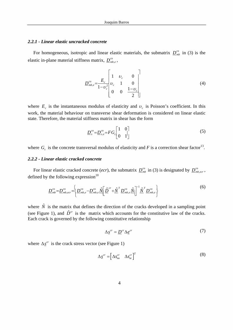
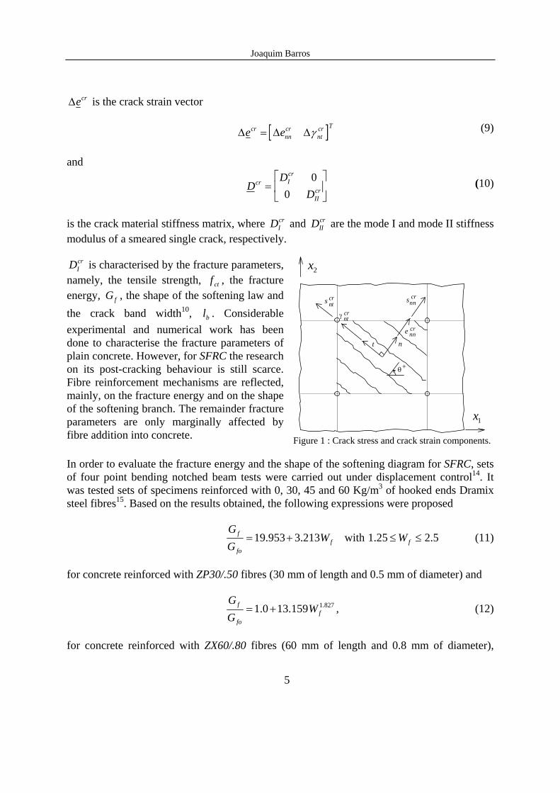
where $N is the matrix that defines the direction of the cracks developed in a sampling point (see Figure 1), and $Dcr is the matrix which accounts for the constitutive law of the cracks. Each crack is governed by the following constitutive relationship
∆ ∆s D ecr cr cr= (7) where ∆scr is the crack stress vector (see Figure 1)
[ ]∆ ∆ ∆s s scrnncr
ntcr T
= (8)
Joaquim Barros
5
∆ecr is the crack strain vector
[ ]∆ ∆ ∆e ecrnncr
ntcr T
= γ (9)
and
DD
Dcr I
cr
IIcr=
⎡
⎣⎢
⎤
⎦⎥
00
(10)
is the crack material stiffness matrix, where DI
cr and DIIcr are the mode I and mode II stiffness
modulus of a smeared single crack, respectively. DI
cr is characterised by the fracture parameters, namely, the tensile strength, f ct , the fracture energy, Gf , the shape of the softening law and the crack band width10, bl . Considerable experimental and numerical work has been done to characterise the fracture parameters of plain concrete. However, for SFRC the research on its post-cracking behaviour is still scarce. Fibre reinforcement mechanisms are reflected, mainly, on the fracture energy and on the shape of the softening branch. The remainder fracture parameters are only marginally affected by fibre addition into concrete.
t
snn
+
crs crnt
ntγ cr
e crnn
n
1x
2x
θ
Figure 1 : Crack stress and crack strain components.
In order to evaluate the fracture energy and the shape of the softening diagram for SFRC, sets of four point bending notched beam tests were carried out under displacement control14. It was tested sets of specimens reinforced with 0, 30, 45 and 60 Kg/m3 of hooked ends Dramix steel fibres15. Based on the results obtained, the following expressions were proposed
ffo
f WGG
213.3953.19 += with 5.225.1 ≤≤ fW (11)
for concrete reinforced with ZP30/.50 fibres (30 mm of length and 0.5 mm of diameter) and
827.1159.130.1 ffo
f WGG
+= , (12)
for concrete reinforced with ZX60/.80 fibres (60 mm of length and 0.8 mm of diameter),
Joaquim Barros
6
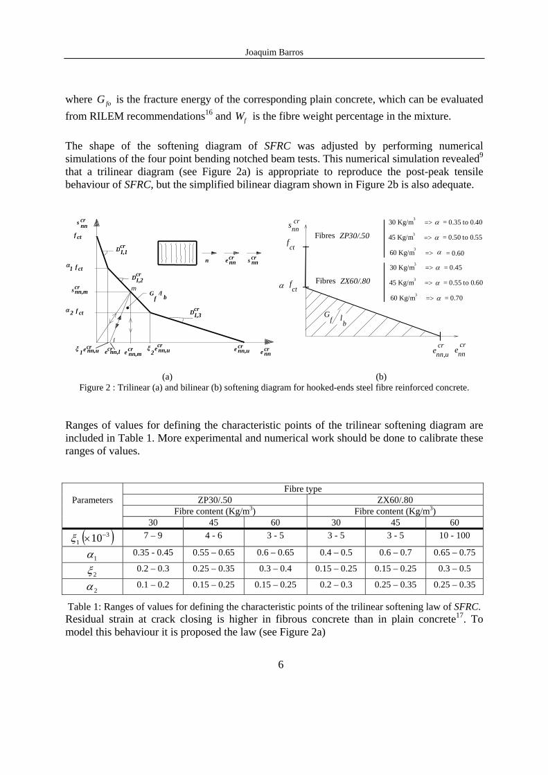
where foG is the fracture energy of the corresponding plain concrete, which can be evaluated from RILEM recommendations16 and Wf is the fibre weight percentage in the mixture. The shape of the softening diagram of SFRC was adjusted by performing numerical simulations of the four point bending notched beam tests. This numerical simulation revealed9 that a trilinear diagram (see Figure 2a) is appropriate to reproduce the post-peak tensile behaviour of SFRC, but the simplified bilinear diagram shown in Figure 2b is also adequate.
s nncr
f ct
f ct1
s nn,mcr
2 ctf
ecrnn,u1 2 nn,uecrnn,ue cr cre nnnn,lecr
nn,mcre
I,3Dcr
crDI,2
crDI,1
Gf b/l
n nnecrnns cr
α
α
ξ ξ
m
l
snncr
fct
enncr
α fct
Gf l
b
Fibres ZP30/.50
30 Kg/m3 α = 0.35 to 0.40=>
45 Kg/m3 α = 0.50 to 0.55=>
60 Kg/m3 α = 0.60=>
enn,ucr
Fibres ZX60/.80
30 Kg/m3 α = 0.45=>
45 Kg/m3 α = 0.55 to 0.60=>
60 Kg/m3 α = 0.70=>
(a) (b)
Figure 2 : Trilinear (a) and bilinear (b) softening diagram for hooked-ends steel fibre reinforced concrete. Ranges of values for defining the characteristic points of the trilinear softening diagram are included in Table 1. More experimental and numerical work should be done to calibrate these ranges of values.
Fibre type Parameters ZP30/.50 ZX60/.80
Fibre content (Kg/m3) Fibre content (Kg/m3) 30 45 60 30 45 60
1ξ ( )310−× 7 – 9 4 - 6 3 - 5 3 - 5 3 - 5 10 - 100
1α 0.35 - 0.45 0.55 – 0.65 0.6 – 0.65 0.4 – 0.5 0.6 – 0.7 0.65 – 0.75
2ξ 0.2 – 0.3 0.25 – 0.35 0.3 – 0.4 0.15 – 0.25 0.15 – 0.25 0.3 – 0.5
2α 0.1 – 0.2 0.15 – 0.25 0.15 – 0.25 0.2 – 0.3 0.25 – 0.35 0.25 – 0.35
Table 1: Ranges of values for defining the characteristic points of the trilinear softening law of SFRC. Residual strain at crack closing is higher in fibrous concrete than in plain concrete17. To model this behaviour it is proposed the law (see Figure 2a)
Joaquim Barros
7
e enn l
crnn mcr
, ,= η (13) where enn m
cr, is the maximum attained crack strain normal to the crack, and
( )[ ]⎥⎥⎦
⎤
⎢⎢⎣
⎡⎟⎟⎠
⎞⎜⎜⎝
⎛−−−−=
f
ffcrmnn d
lC
We exp11000exp1 ,η (14)
with l f and d f being the fibre length and fibre diameter. For C parameter it is advanced a value of 165, but more experimental research is needed to calibrate this parameter. The fracture mode II modulus, DII
cr , is obtained from the expression10
D GIIcr
c=−ββ1
(15)
where β is the shear retention factor determined from
p
crunn
crnn
ee
⎥⎥⎦
⎤
⎢⎢⎣
⎡−=
,
1β (p=1, 2 or 3) (16)
for plain concrete, with enn u
cr, being the ultimate normal crack strain (see Figure 2), and
⎟⎟⎠
⎞⎜⎜⎝
⎛−= cr
unn
crnn
f
f
f ee
ld
WM
,
expβ (17)
for SFRC. M parameter must be evaluated from experimental research. Based on the reduced data available, a value of 980 is proposed for M. The shear retention factor for conventionally reinforced concrete is evaluated from an expression proposed by Cervenka18
2
1
ln
CCecr
nn⎟⎟⎠
⎞⎜⎜⎝
⎛
−=β (18)
with
Joaquim Barros
8
015.0
005.057 ,
1
−+=
eefeqC
ρ, C eq ef
e
2 10 2 50 005
0 015= −
−.
..
,ρ (19)
where efeq ,ρ is the equivalent effective reinforcement9
ρ ρ θeq ef i ef ii
nr
, , cos==∑ 4
1 (20)
nr is the number of sets of reinforcing layers crossing the crack, ρi ef, is the effective reinforcing ratio19 of layer i and θi is the angle between the reinforcing layer i and the crack direction. 2.2.3 - Elasto-plastic uncracked concrete
For elasto-plastic (ep) uncracked concrete, the in-plane material stiffness matrix combD in (3)
is defined by
aDah
DaaDDDD co
embT
coemb
Tcoembco
embco
epmbcomb
,
,,,, +−== (21)
where a is the flow vector and h is the hardening modulus20. The hardening modulus depends on the equivalent stress-plastic strain relationship used for concrete in compression. For plain concrete this relationship is based on the stress-strain relationship proposed by CEB-FIP Model Code 199019. However, the uniaxial compression tests under displacement control have shown that this expression is not appropriate to simulate the post-peak behaviour of SFRC9. Based on the results obtained with uniaxial compression tests a new expression was proposed for SFRC14. In the plasticity approach concrete strain, coε , is decomposed into an
elastic, coeε , and a plastic, co
pε , contributions. Inserting this decomposition into the expression proposed for SFRC14 holds
01
1
1
2
1
=−⎟⎟⎠
⎞⎜⎜⎝
⎛+++⎟⎟
⎠
⎞⎜⎜⎝
⎛−+
⎟⎟⎠
⎞⎜⎜⎝
⎛+
coc
cop
c
pA
coc
copc
cccco
pcoc
c fB
pBq
BfAq
εε
εεσσσε
εσ (22)
with
Joaquim Barros
9
c
c
EEA 1= , q p A= − −1 , co
ccEB 1ε= (23)
where f
cooc
coc W0002.011 +=εε , (24)
p Wf= − −10 0 919 0 394. . exp( . ) (25) for ZP30/.50 fibres and f
coc
coc W00026.0101 +=εε , (26)
p Wf= − −10 0 722 0144. . exp( . ) (27) for ZX60/.80 fibres. 1cE is the secant modulus of elasticity19 and co
oc1ε and coc1ε are the strain at
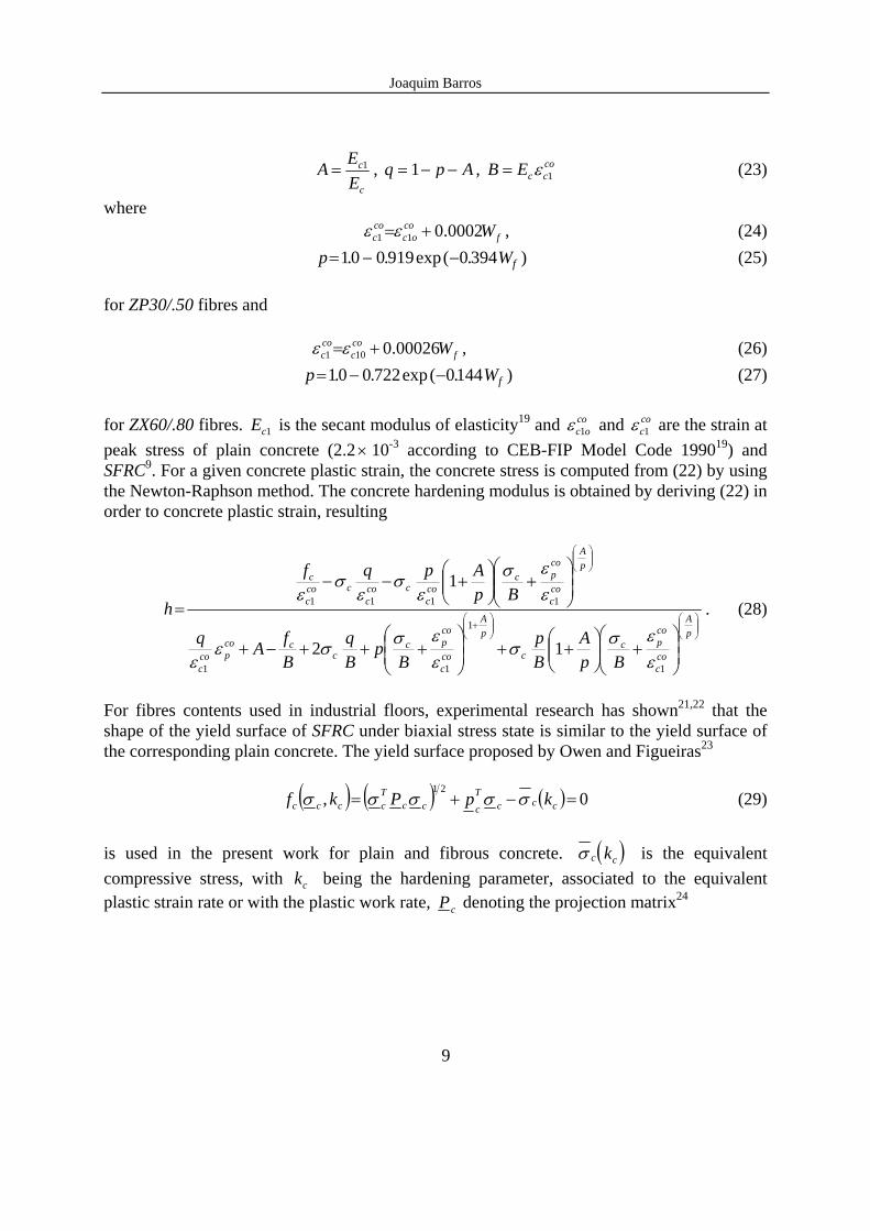
peak stress of plain concrete (2.2× 10⁻³ according to CEB-FIP Model Code 199019) and SFRC9. For a given concrete plastic strain, the concrete stress is computed from (22) by using the Newton-Raphson method. The concrete hardening modulus is obtained by deriving (22) in order to concrete plastic strain, resulting
⎟⎟⎠
⎞⎜⎜⎝
⎛⎟⎟⎠
⎞⎜⎜⎝
⎛+
⎟⎟⎠
⎞⎜⎜⎝
⎛
⎟⎟⎠
⎞⎜⎜⎝
⎛+⎟⎟
⎠
⎞⎜⎜⎝
⎛++⎟
⎟⎠
⎞⎜⎜⎝
⎛+++−+
⎟⎟⎠
⎞⎜⎜⎝
⎛+⎟⎟
⎠
⎞⎜⎜⎝
⎛+−−
=pA
coc
copc
c
pA
coc
copc
ccco
pcoc
pA
coc
copc
coc
ccoc
ccoc
c
BpA
Bp
Bp
Bq
BfAq
BpApqf
h
1
1
11
1111
12
1
εεσσ
εεσσε
ε
εεσ
εσ
εσ
ε. (28)
For fibres contents used in industrial floors, experimental research has shown21,22 that the shape of the yield surface of SFRC under biaxial stress state is similar to the yield surface of the corresponding plain concrete. The yield surface proposed by Owen and Figueiras23 ( ) ( ) ( ) 0,
21=−+= ccc
T
cccTcccc kpPkf σσσσσ (29)
is used in the present work for plain and fibrous concrete. ( )σ c ck is the equivalent compressive stress, with kc being the hardening parameter, associated to the equivalent plastic strain rate or with the plastic work rate, Pc denoting the projection matrix24
Joaquim Barros
10
P
a b bb a bb b a
c
c =
⎡
⎣
⎢⎢⎢⎢
⎤
⎦
⎥⎥⎥⎥
000
0 0 0
(30)
and pc being the projection vector,
[ ]
p d p
d
cT
=
=
1
1 1 1 0. (31)
Scalar parameters a, b, c and d are defined as
a =⎛⎝⎜
⎞⎠⎟
0 3552
2., b = ⎛⎝⎜
⎞⎠⎟ −
0 3552
13552
2. ., c = ×3 1355. , d =
0 3552
.. (32)
2.2.4 - Elasto-plastic cracked concrete
For elasto-plastic cracked concrete (epcr), the submatrix combD of (3) is obtained from the
following expression
⎭⎬⎫
⎩⎨⎧
⎥⎦⎤
⎢⎣⎡ +−==
−co
epmb
Tcoepmb
Tcrcoepmb
coepmb
coepcrmb
comb DNNDNDNDDDD ,
1
,,,,ˆˆˆˆˆ (33)
where co
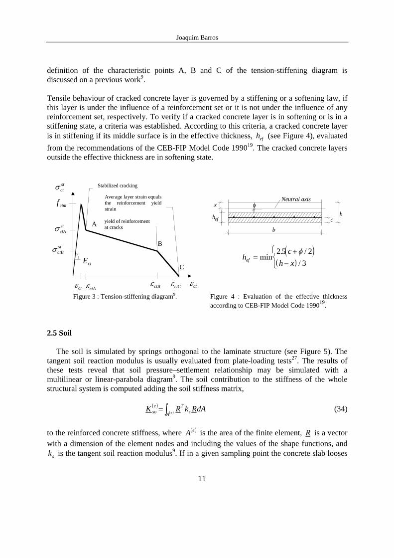
epmbD , was defined in (21). 2.3 - Reinforcement material constitutive laws In the present model a plain or fibrous concrete laminate structure can be reinforced with sets of smeared steel bars. The stress-strain relationship of a steel bar can be simulated by a linear-parabola diagram or by a multilinear diagram9. The material non-linear behaviour of a steel bar is reproduced under the elasto-plasticity framework9. 2.4 -Tension stiffening model A tension-stiffening model was developed for laminar concrete structures that can be reinforced with several sets of smeared bars with different orientation and properties. This model is based on the principles proposed by Link et al.25 and Massicotte et al.26, and can be represented by the post-peak stress-strain trilinear diagram illustrated in Figure 3. The
Joaquim Barros
11
definition of the characteristic points A, B and C of the tension-stiffening diagram is discussed on a previous work9. Tensile behaviour of cracked concrete layer is governed by a stiffening or a softening law, if this layer is under the influence of a reinforcement set or it is not under the influence of any reinforcement set, respectively. To verify if a cracked concrete layer is in softening or is in a stiffening state, a criteria was established. According to this criteria, a cracked concrete layer is in stiffening if its middle surface is in the effective thickness, efh (see Figure 4), evaluated from the recommendations of the CEB-FIP Model Code 199019. The cracked concrete layers outside the effective thickness are in softening state.
εct
Eci
εcrεctCεctBεctA
σ ctBst
σ ctAst
σ ctst
f ctm
C
B
A
Stabilized cracking
yield of reinforcementat cracks
Average layer strain equalsthe reinforcement yieldstrain
hefh
b
c
φxNeutral axis
( )( )
hc
h xef =+
−
⎧⎨⎩
min. /
/2 5 2
3φ
Figure 3 : Tension-stiffening diagram9. Figure 4 : Evaluation of the effective thickness according to CEB-FIP Model Code 199019.
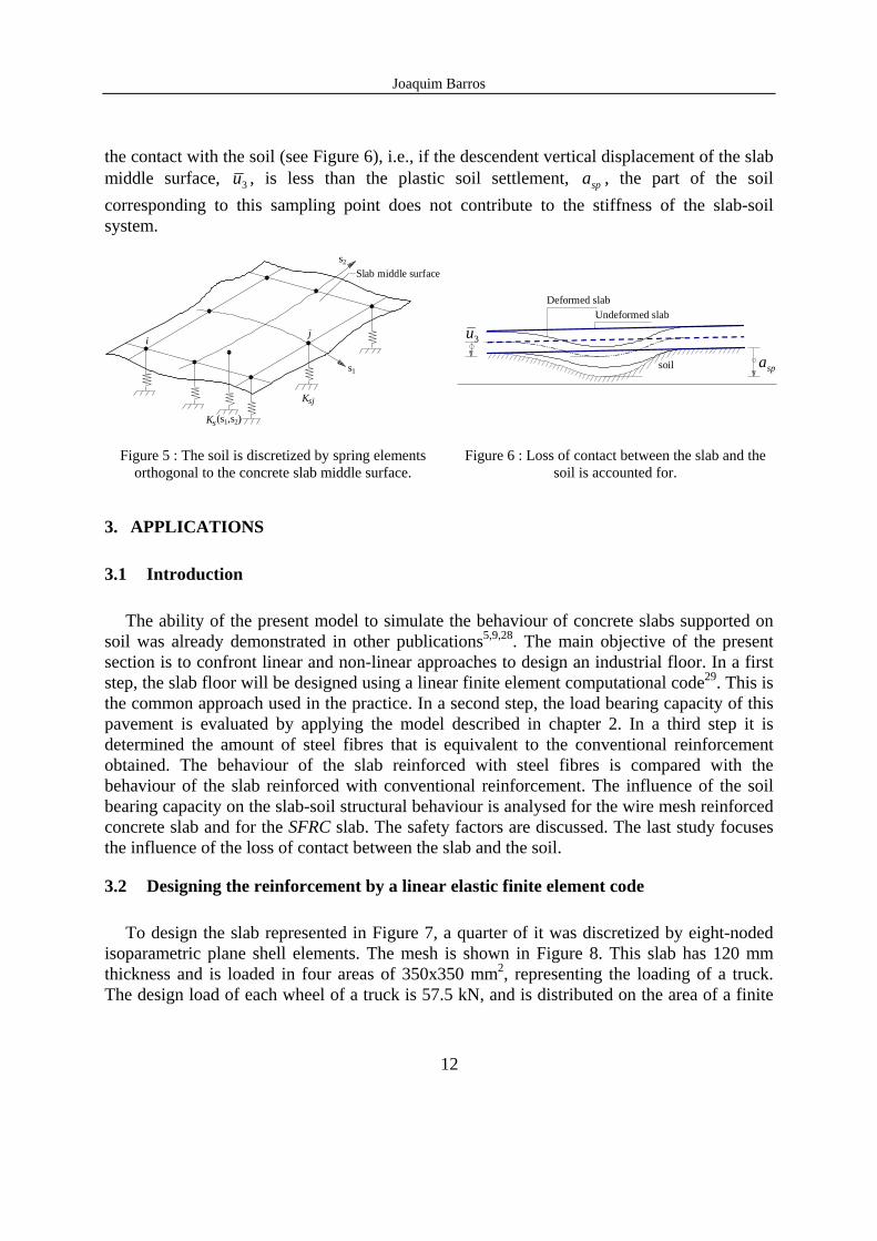
2.5 Soil The soil is simulated by springs orthogonal to the laminate structure (see Figure 5). The tangent soil reaction modulus is usually evaluated from plate-loading tests27. The results of these tests reveal that soil pressure–settlement relationship may be simulated with a multilinear or linear-parabola diagram9. The soil contribution to the stiffness of the whole structural system is computed adding the soil stiffness matrix, ( )
( )∫= eA sTe
so dARkRK (34)
to the reinforced concrete stiffness, where ( )eA is the area of the finite element, R is a vector with a dimension of the element nodes and including the values of the shape functions, and
sk is the tangent soil reaction modulus9. If in a given sampling point the concrete slab looses
Joaquim Barros
12
the contact with the soil (see Figure 6), i.e., if the descendent vertical displacement of the slab middle surface, 3u , is less than the plastic soil settlement, spa , the part of the soil corresponding to this sampling point does not contribute to the stiffness of the slab-soil system.
Slab middle surface
(s1,s2)
ji
Ksj
Ks
s2
s1
spa3u
soil
Undeformed slabDeformed slab
Figure 5 : The soil is discretized by spring elements orthogonal to the concrete slab middle surface.
Figure 6 : Loss of contact between the slab and the soil is accounted for.
3. APPLICATIONS
3.1 Introduction
The ability of the present model to simulate the behaviour of concrete slabs supported on soil was already demonstrated in other publications5,9,28. The main objective of the present section is to confront linear and non-linear approaches to design an industrial floor. In a first step, the slab floor will be designed using a linear finite element computational code29. This is the common approach used in the practice. In a second step, the load bearing capacity of this pavement is evaluated by applying the model described in chapter 2. In a third step it is determined the amount of steel fibres that is equivalent to the conventional reinforcement obtained. The behaviour of the slab reinforced with steel fibres is compared with the behaviour of the slab reinforced with conventional reinforcement. The influence of the soil bearing capacity on the slab-soil structural behaviour is analysed for the wire mesh reinforced concrete slab and for the SFRC slab. The safety factors are discussed. The last study focuses the influence of the loss of contact between the slab and the soil.
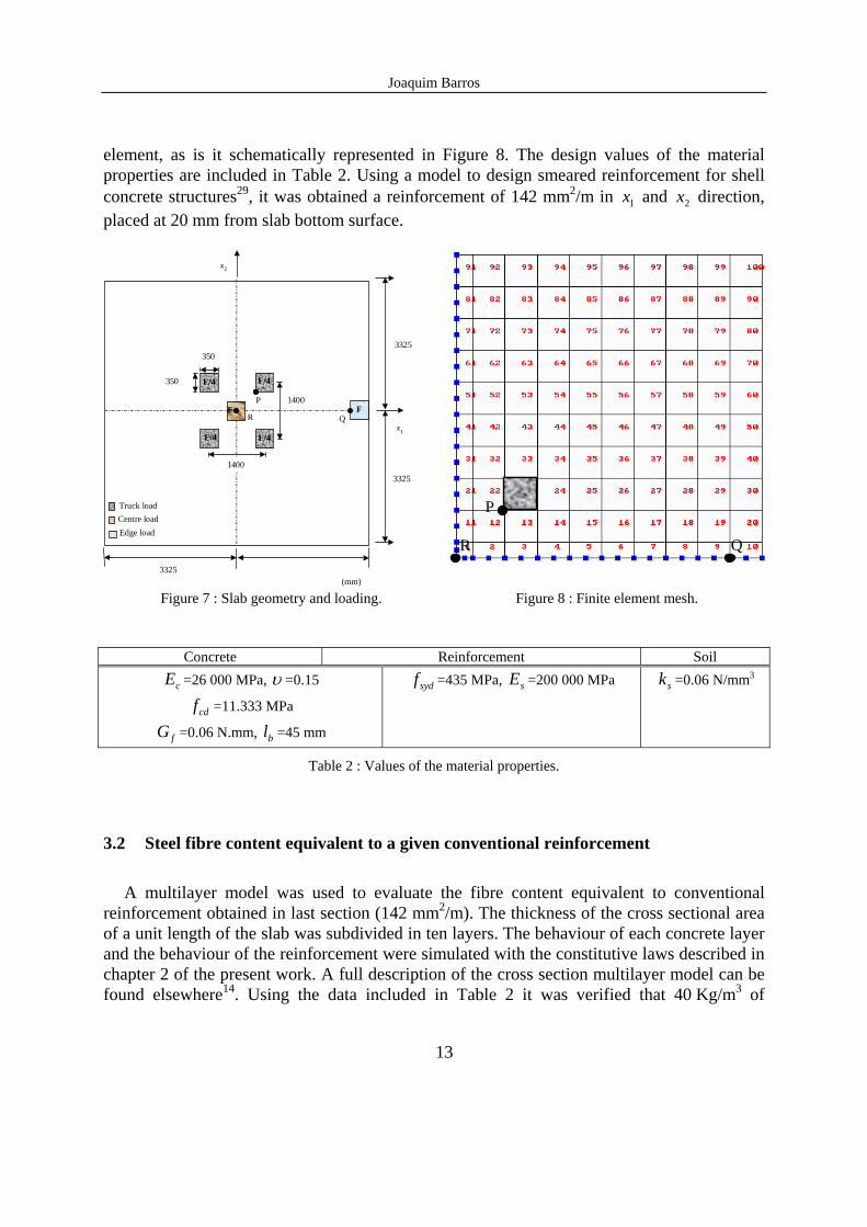
3.2 Designing the reinforcement by a linear elastic finite element code To design the slab represented in Figure 7, a quarter of it was discretized by eight-noded isoparametric plane shell elements. The mesh is shown in Figure 8. This slab has 120 mm thickness and is loaded in four areas of 350x350 mm2, representing the loading of a truck. The design load of each wheel of a truck is 57.5 kN, and is distributed on the area of a finite
Joaquim Barros
13
element, as is it schematically represented in Figure 8. The design values of the material properties are included in Table 2. Using a model to design smeared reinforcement for shell concrete structures29, it was obtained a reinforcement of 142 mm2/m in 1x and 2x direction, placed at 20 mm from slab bottom surface.
3325
14003325
3325
(mm)
1400
350
350
2x
F/4
1x
Truck loadCentre loadEdge load
P
R QF F
F/4
F/4F/4
P
QR
Figure 7 : Slab geometry and loading. Figure 8 : Finite element mesh.
Concrete Reinforcement Soil
cE =26 000 MPa, υ =0.15
cdf =11.333 MPa
fG =0.06 N.mm, bl =45 mm
sydf =435 MPa, sE =200 000 MPa sk =0.06 N/mm3
Table 2 : Values of the material properties.
3.2 Steel fibre content equivalent to a given conventional reinforcement
A multilayer model was used to evaluate the fibre content equivalent to conventional reinforcement obtained in last section (142 mm2/m). The thickness of the cross sectional area of a unit length of the slab was subdivided in ten layers. The behaviour of each concrete layer and the behaviour of the reinforcement were simulated with the constitutive laws described in chapter 2 of the present work. A full description of the cross section multilayer model can be found elsewhere14. Using the data included in Table 2 it was verified that 40 Kg/m3 of
Joaquim Barros
14
ZX60/.80 hooked ends steel fibres provides a maximum resisting moment similar to the maximum resisting moment registered in the cross section reinforced with the wire mesh. It should be pointed that the SFRC slabs have identical resistance under positive and negative moments, which is equivalent to slabs conventionally reinforced in both faces (2x142 = 284mm2/m).
3.3 Material non-linear analysis
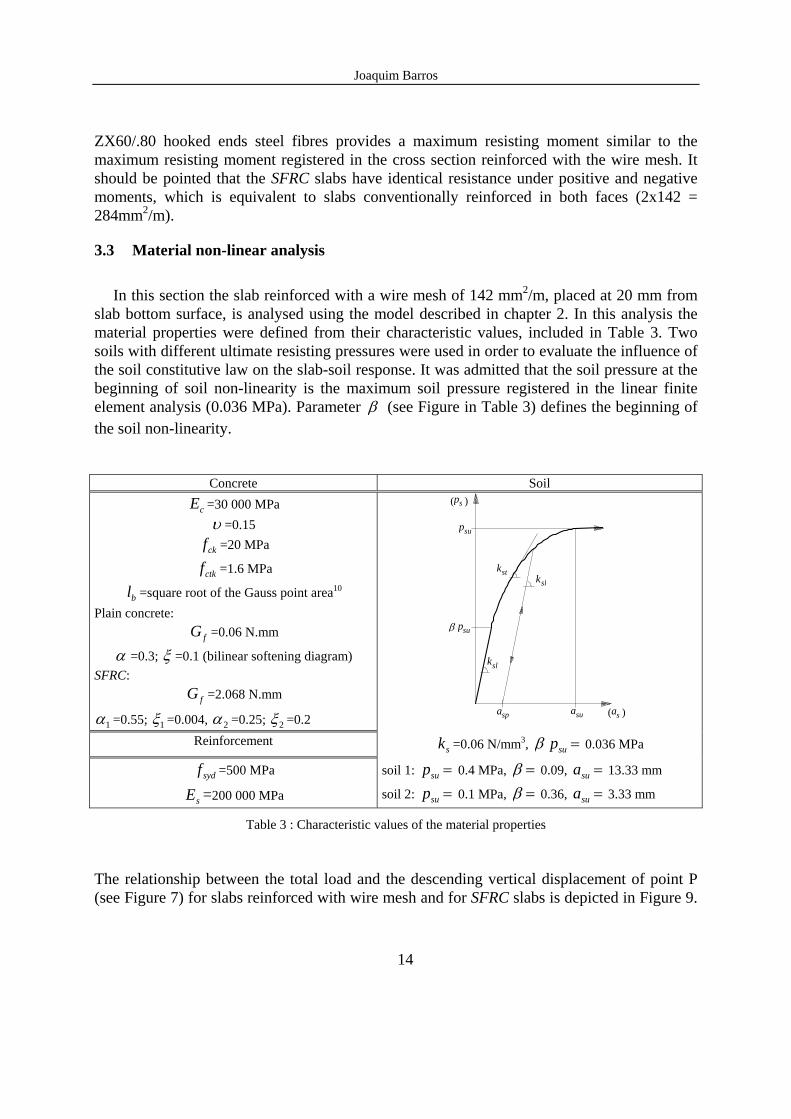
In this section the slab reinforced with a wire mesh of 142 mm2/m, placed at 20 mm from slab bottom surface, is analysed using the model described in chapter 2. In this analysis the material properties were defined from their characteristic values, included in Table 3. Two soils with different ultimate resisting pressures were used in order to evaluate the influence of the soil constitutive law on the slab-soil response. It was admitted that the soil pressure at the beginning of soil non-linearity is the maximum soil pressure registered in the linear finite element analysis (0.036 MPa). Parameter β (see Figure in Table 3) defines the beginning of the soil non-linearity.
Concrete Soil
cE =30 000 MPa υ =0.15
ckf =20 MPa
ctkf =1.6 MPa
bl =square root of the Gauss point area10 Plain concrete:
fG =0.06 N.mm
α =0.3; ξ =0.1 (bilinear softening diagram) SFRC:
fG =2.068 N.mm
1α =0.55; 1ξ =0.004, 2α =0.25; 2ξ =0.2 asp asu
psu
β psu
kstksl
ksl
as( )
ps( )
Reinforcement sk =0.06 N/mm3, =supβ 0.036 MPa
sydf =500 MPa
sE =200 000 MPa soil 1: =sup 0.4 MPa, =β 0.09, =sua 13.33 mm
soil 2: =sup 0.1 MPa, =β 0.36, =sua 3.33 mm
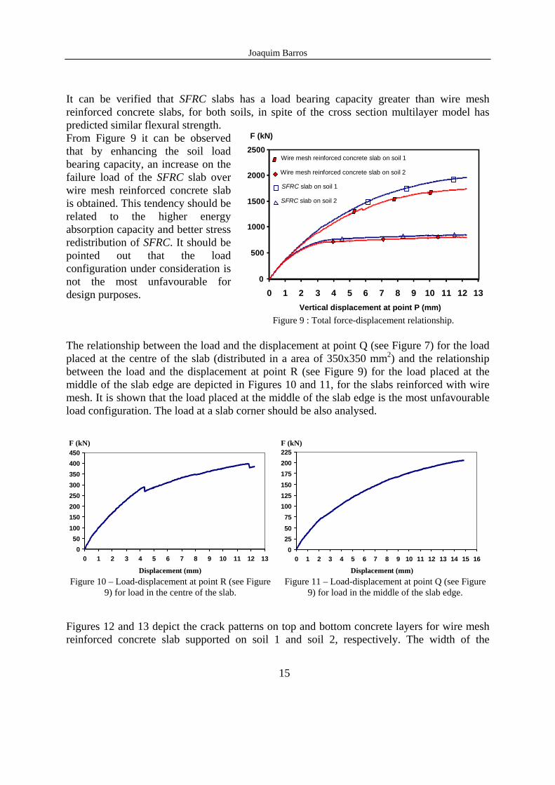
Table 3 : Characteristic values of the material properties The relationship between the total load and the descending vertical displacement of point P (see Figure 7) for slabs reinforced with wire mesh and for SFRC slabs is depicted in Figure 9.
Joaquim Barros
15
It can be verified that SFRC slabs has a load bearing capacity greater than wire mesh reinforced concrete slabs, for both soils, in spite of the cross section multilayer model has predicted similar flexural strength. From Figure 9 it can be observed that by enhancing the soil load bearing capacity, an increase on the failure load of the SFRC slab over wire mesh reinforced concrete slab is obtained. This tendency should be related to the higher energy absorption capacity and better stress redistribution of SFRC. It should be pointed out that the load configuration under consideration is not the most unfavourable for design purposes.
0
500
1000
1500
2000
2500
0 1 2 3 4 5 6 7 8 9 10 11 12 13Vertical displacement at point P (mm)
F (kN)
Wire mesh reinforced concrete slab on soil 1
Wire mesh reinforced concrete slab on soil 2
SFRC slab on soil 1
SFRC slab on soil 2
Figure 9 : Total force-displacement relationship. The relationship between the load and the displacement at point Q (see Figure 7) for the load placed at the centre of the slab (distributed in a area of 350x350 mm2) and the relationship between the load and the displacement at point R (see Figure 9) for the load placed at the middle of the slab edge are depicted in Figures 10 and 11, for the slabs reinforced with wire mesh. It is shown that the load placed at the middle of the slab edge is the most unfavourable load configuration. The load at a slab corner should be also analysed.
050
100150200250300350400450
0 1 2 3 4 5 6 7 8 9 10 11 12 13
F (kN)
Displacement (mm) Figure 10 – Load-displacement at point R (see Figure
9) for load in the centre of the slab.
0255075
100125150175200225
0 1 2 3 4 5 6 7 8 9 10 11 12 13 14 15 16
F (kN)
Displacement (mm) Figure 11 – Load-displacement at point Q (see Figure
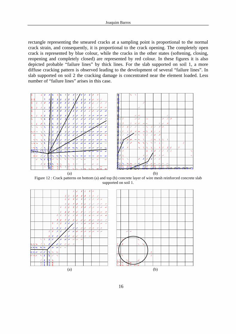
9) for load in the middle of the slab edge. Figures 12 and 13 depict the crack patterns on top and bottom concrete layers for wire mesh reinforced concrete slab supported on soil 1 and soil 2, respectively. The width of the
Joaquim Barros
16
rectangle representing the smeared cracks at a sampling point is proportional to the normal crack strain, and consequently, it is proportional to the crack opening. The completely open crack is represented by blue colour, while the cracks in the other states (softening, closing, reopening and completely closed) are represented by red colour. In these figures it is also depicted probable “failure lines” by thick lines. For the slab supported on soil 1, a more diffuse cracking pattern is observed leading to the development of several “failure lines”. In slab supported on soil 2 the cracking damage is concentrated near the element loaded. Less number of “failure lines” arises in this case.
(a) (b)
Figure 12 : Crack patterns on bottom (a) and top (b) concrete layer of wire mesh reinforced concrete slab supported on soil 1.
(a) (b)
Joaquim Barros
17
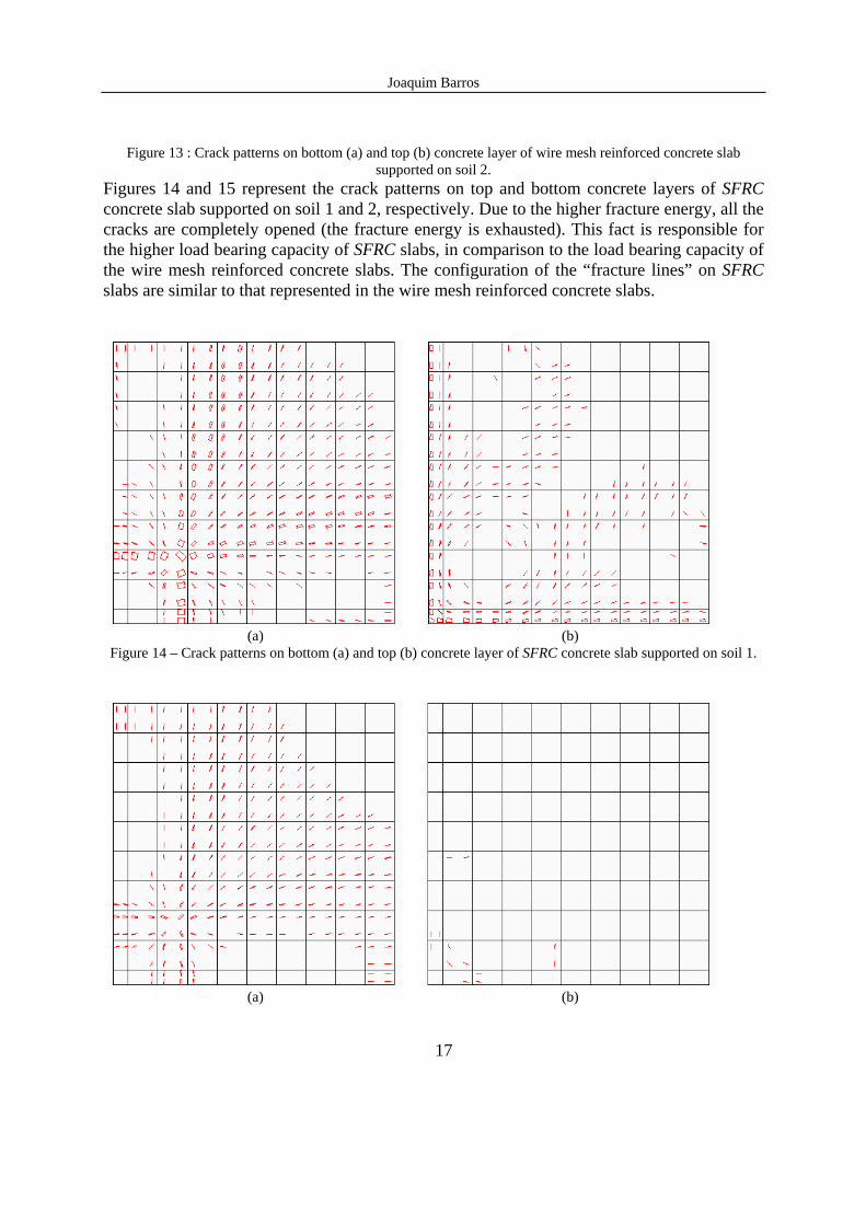
Figure 13 : Crack patterns on bottom (a) and top (b) concrete layer of wire mesh reinforced concrete slab supported on soil 2.
Figures 14 and 15 represent the crack patterns on top and bottom concrete layers of SFRC concrete slab supported on soil 1 and 2, respectively. Due to the higher fracture energy, all the cracks are completely opened (the fracture energy is exhausted). This fact is responsible for the higher load bearing capacity of SFRC slabs, in comparison to the load bearing capacity of the wire mesh reinforced concrete slabs. The configuration of the “fracture lines” on SFRC slabs are similar to that represented in the wire mesh reinforced concrete slabs.
(a) (b)
Figure 14 – Crack patterns on bottom (a) and top (b) concrete layer of SFRC concrete slab supported on soil 1.
(a) (b)
Joaquim Barros
18
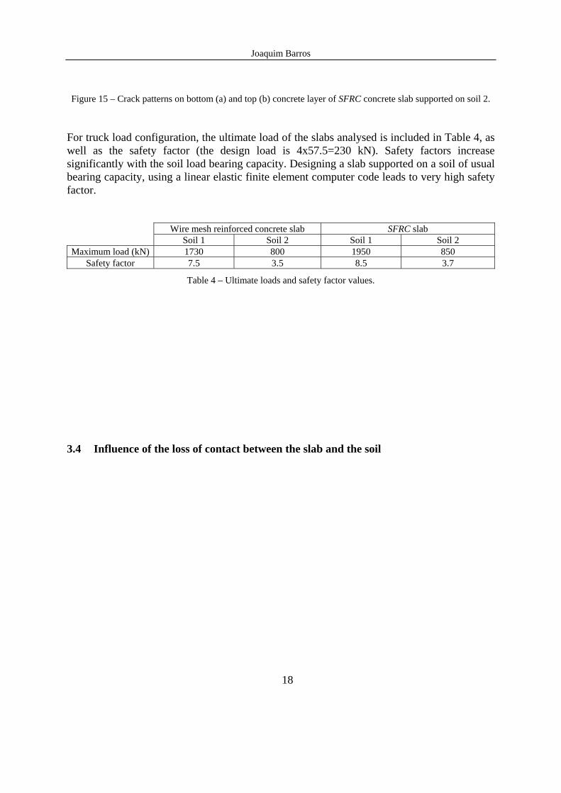
Figure 15 – Crack patterns on bottom (a) and top (b) concrete layer of SFRC concrete slab supported on soil 2. For truck load configuration, the ultimate load of the slabs analysed is included in Table 4, as well as the safety factor (the design load is 4x57.5=230 kN). Safety factors increase significantly with the soil load bearing capacity. Designing a slab supported on a soil of usual bearing capacity, using a linear elastic finite element computer code leads to very high safety factor.
Wire mesh reinforced concrete slab SFRC slab Soil 1 Soil 2 Soil 1 Soil 2
Maximum load (kN) 1730 800 1950 850 Safety factor 7.5 3.5 8.5 3.7
Table 4 – Ultimate loads and safety factor values.
3.4 Influence of the loss of contact between the slab and the soil
Joaquim Barros
19
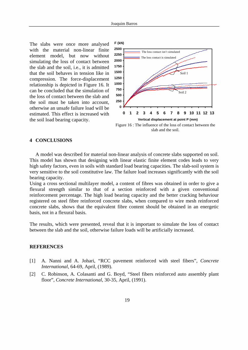
The slabs were once more analysed with the material non-linear finite element model, but now without simulating the loss of contact between the slab and the soil, i.e., it is admitted that the soil behaves in tension like in compression. The force-displacement relationship is depicted in Figure 16. It can be concluded that the simulation of the loss of contact between the slab and the soil must be taken into account, otherwise an unsafe failure load will be estimated. This effect is increased with the soil load bearing capacity.
0250
500750
10001250
150017502000
22502500
0 1 2 3 4 5 6 7 8 9 10 11 12 13Vertical displacement at point P (mm)
F (kN)
Soil 2
Soil 1
The loss contact isn’t simulated
The loss contact is simulated
Figure 16 : The influence of the loss of contact between the
slab and the soil.
4 CONCLUSIONS
A model was described for material non-linear analysis of concrete slabs supported on soil.
This model has shown that designing with linear elastic finite element codes leads to very high safety factors, even in soils with standard load bearing capacities. The slab-soil system is very sensitive to the soil constitutive law. The failure load increases significantly with the soil bearing capacity. Using a cross sectional multilayer model, a content of fibres was obtained in order to give a flexural strength similar to that of a section reinforced with a given conventional reinforcement percentage. The high load bearing capacity and the better cracking behaviour registered on steel fibre reinforced concrete slabs, when compared to wire mesh reinforced concrete slabs, shows that the equivalent fibre content should be obtained in an energetic basis, not in a flexural basis. The results, which were presented, reveal that it is important to simulate the loss of contact between the slab and the soil, otherwise failure loads will be artificially increased.
REFERENCES
[1] A. Nanni and A. Johari, “RCC pavement reinforced with steel fibers”, Concrete
International, 64-69, April, (1989). [2] C. Robinson, A. Colasanti and G. Boyd, “Steel fibers reinforced auto assembly plant
floor”, Concrete International, 30-35, April, (1991).
Joaquim Barros
20
[3] P.C. Tatnall and L. Kuitenbrouwer, “Steel fiber reinforced concrete in industrial floors”, Concrete International, 43-47, December, (1992).
[4] H. Falkner and M. Teutsch, Comperative investigations of plain and steel fibre reinforced industrial ground slabs, Institut Fur Baustoffe, Massivbau und Brandschutz, Nº 102, (1993).
[5] J.A.O. Barros and J.A. Figueiras, ”Experimental behaviour of fiber concrete slabs on soil”, Journal Mechanics of Cohesive-frictional Materials, 3, 277-290, (1998).
[6] H.M. Westergaard, “Stresses in concrete pavements computed by theoretical analysis”, Publ. Roads 7, (1926-27).
[7] A. Losberg, Design methods for structurally reinforced concrete pavements, Transactions of Chalmers University of Technology Gothenburg, Sweden, (1961).
[8] G.G. Meyerhof, “Load carrying capacity of concrete pavements”, Journal of the Soil Mechanics and Foundations Division, June, (1962).
[9] J.A.O.Barros, Comportamento do betão reforçado com fibras - análise experimental e simulação numérica PhD dissertation, Civil Eng. Dept., Faculty of Engineering, University of Oporto, Portugal (in Portuguese), (1995).
[10] Rots, J.G., Computational modeling of concrete fracture, PhD Dissertation, Delft University of Technology, (1988).
[11] R. De Borst and P. Nauta, “Non-orthogonal cracks in a smeared finite element model”, Eng. Computations, 2, 35-46, March, (1985).
[12] E. Reissner, “The effect of transverse shear deformation on the bending elastic plates”, Jour. Appl. Mech., 12, 69-76, (1945).
[13] T.S. Chow, “On the propagation of flexural waves in an orthotropic laminated plate and its response to an impulsive load”, Jour. of Composite Materials, 5, 306-319, (1971).
[14] J.A.O. Barros, J.A. Figueiras, “Flexural behavior of steel fiber reinforced concrete: testing and modelling”, Journal of Materials in Civil Engineering, ASCE. (accepted to be published)
[15] Bekaert Specification, Dramix fibres hors fils d’acier pour reinforcement de betón et mortier, Bekaert N.V., (1991).
[16] RILEM TC 50-FMC, “Determination of fracture energy of mortar and concrete by means of three-point bend tests on notched beams”, Materials and Structures, 18(106), 285-290, (1985).
[17] V.S. Gopalaratnam and S.P. Shah, “Tensile failure of steel fibre-reinforced mortar”, Jour. of Eng. Mech., ASCE, 113(5), 635-653, May, (1987).
[18] V. Cervenka, H. Pukl and R. Eligehausen, “Computer simulation of anchoring technique and design of concrete structures”, Proc. Second Intern. Conf. on Computer Aided Analysis and Desing of Concrete Structures, Zell am See, Austria, 1-19, (1990).
Joaquim Barros
21
[19] CEB-FIP Model Code 1990. Comite Euro-International du Beton, Bulletin d’Information nº 213/214, Ed. Thomas Telford, (1993).
[20] G. Hofstetter and H.A. Mang, Computational mechanics of reinforced concrete structures, Ed. Vieweg, (1995).
[21] W. S. Yin, E.C.M. Su, M.A. Mansur and T.T.C. Hsu, “Biaxial tests of plain and fiber concrete”, ACI Materials Journal, 86(3), 236-243, May-June (1989).
[22] L.A. Traina, S.A. Mansour, “Biaxial strength and deformational behaviour of plain and steel fiber concrete”, ACI Materials Journal, 88(4), 354-363, July-Aug. (1991).
[23] Figueiras, J.A., Ultimate load analysis of anisotropic and reinforced concrete plates and shells, Ph.D. Thesis, C/Ph/72/83, Uni. College of Swansea, (1983).
[24] Feenstra, P.H., Computational aspects of biaxial stress in plain and reinforced concrete, PhD Thesis Delft University of Technology, (1993).
[25] R.A. Link, A.E. Elwi, A. Scanlon, “Biaxial tension stiffening due to generally oriented reinforced layers”, Jour. of Eng. Mech., ASCE, 115(8), 1647-1662, August, (1989).
[26] B. Massicote, A.E. Elwi, J.G. MacGregor, “Tension-stiffening model for planar reinforced concrete members”, Jour. of Struct. Eng., ASCE, 116(11), 3039-3058, November, (1990).
[27] ASTM D 1194-72, Bearing capacity of soil for static load and spread footing, (1972). [28] J.A. Barros and J.A. Figueiras, “Simulação numérica do comportamento de lajes de
betão reforçado com fibras de aço apoiadas em solo”, 6º Encontro Nacional sobre Estruturas Pré-Esforçadas, Lisboa, LNEC, 1-57 a 1-70, Novembro, (1996).
[29] Alvaro F.M. Azevedo and J.A. Barros, Manual de utilização do programa FEMIX-versão 3.0, FEMopen Consultoria e Software de Engenharia, 1998.