Slabs and Flat Slabs - concretecentre.com · Slabs and Flat Slabs ... • Punching shear –e.g....
40
EC2 Webinar - Autumn 2017 Lecture 5/1 Slabs and Flat Slabs Lecture 5 19 th October 2017 Contents – Lecture 5 • Designing for shear in slabs - including punching shear • Detailing – Solid slabs • Flat Slab Design – includes flexure worked example • Exercise - Punching shear
Transcript of Slabs and Flat Slabs - concretecentre.com · Slabs and Flat Slabs ... • Punching shear –e.g....

EC2 Webinar - Autumn 2017 Lecture 5/1
Slabs and Flat Slabs
Lecture 5
19th October 2017
Contents – Lecture 5
• Designing for shear in slabs - including punching shear
• Detailing – Solid slabs
• Flat Slab Design – includes flexure worked example
• Exercise - Punching shear

EC2 Webinar - Autumn 2017 Lecture 5/2
Designing for shear in slabs
• When shear reinforcement is not required – e.g.
usually one and two-way spanning slabs
• Punching shear – e.g. flat slabs and pad foundations
Shear
There are three approaches to designing for shear:
• When shear reinforcement is not required e.g. usually slabs
• When shear reinforcement is required e.g. Beams, see Lecture 3
• Punching shear requirements e.g. flat slabs
The maximum shear strength in the UK should not exceed that of class C50/60 concrete

EC2 Webinar - Autumn 2017 Lecture 5/3
Shear resistance without shear reinforcement
where:
k = 1 + √√√√(200/d) ≤≤≤≤ 2.0
ρρρρl = Asl/bwd ≤≤≤≤ 0.02
Asl = area of the tensile reinforcement,
bw = smallest width of the cross-section in the tensile area [mm]
σσσσ cp = NEd/Ac < 0.2 fcd [MPa] Compression +ve
NEd = axial force in the cross-section due to loading or pre-stressing [in N]
Ac = area of concrete cross section [mm2]
VRd,c = [0.12k(100 ρ l fck)1/3 + 0.15σcp] bwd (6.2.a)
with a minimum of
VRd,c = (0.035k3/2fck
1/2 + 0.15 σcp) bwd (6.2.b)
Without Shear ReinforcementEC2: Cl. 6.2.2 Concise: 7.2

EC2 Webinar - Autumn 2017 Lecture 5/4
Shear – vRd,c- Concise Table 7.1 or 15.6
vRd,c resistance of members without shear reinforcement, MPa
As
(bd) %
Effective depth, d (mm)
≤≤≤≤200 225 250 275 300 350 400 450 500 600 750
0.25 0.54 0.52 0.50 0.48 0.47 0.45 0.43 0.41 0.40 0.38 0.36
0.50 0.59 0.57 0.56 0.55 0.54 0.52 0.51 0.49 0.48 0.47 0.45
0.75 0.68 0.66 0.64 0.63 0.62 0.59 0.58 0.56 0.55 0.53 0.51
1.00 0.75 0.72 0.71 0.69 0.68 0.65 0.64 0.62 0.61 0.59 0.57
1.25 0.80 0.78 0.76 0.74 0.73 0.71 0.69 0.67 0.66 0.63 0.61
1.50 0.85 0.83 0.81 0.79 0.78 0.75 0.73 0.71 0.70 0.67 0.65
1.75 0.90 0.87 0.85 0.83 0.82 0.79 0.77 0.75 0.73 0.71 0.68
2.00 0.94 0.91 0.89 0.87 0.85 0.82 0.80 0.78 0.77 0.74 0.71
k 2.00 1.94 1.89 1.85 1.82 1.76 1.71 1.67 1.63 1.58 1.52
Table derived from: vRd,c = 0.12 k (100ρI fck)(1/3) ≥ 0.035 k1.5 fck
0.5 where k = 1 + √(200/d) ≤ 2 and ρI = As/(bd) ≤ 0.02
Note: This table has been prepared for fck = 30. Where ρI exceeds 0.40% the following factors may be used:
fck 25 28 32 35 40 45 50
factor 0.94 0.98 1.02 1.05 1.10 1.14 1.19
Shear in Slabs
Most slabs do not require shear
reinforcement
∴Check VEd < VRd,c
Where VRd,c is shear resistance of
members without reinforcement
vRd,c = 0.12 k (100 ρI fck)1/3
≥ 0.035 k1.5 fck0.5
Where VEd > VRd,c,
shear reinforcement is required
and the strut inclination method
should be used
How-to Compendium p21

EC2 Webinar - Autumn 2017 Lecture 5/5
Punching shear
Punching shear symbols
ui = ith perimeter.
u1 = basic control perimeter at 2d
u1* = reduced basic control perimeter
u0 = column perimeter
d = average effective depth
k = coeff. depending on column shape –see Table 6.1
W1 = a shear distribution factor – see 6.4.3(3)
Punching shear does not use the Variable Strut inclination method
and is similar to BS 8110 methods
• The basic control perimeter is set at 2d from the loaded area
• The shape of control perimeters have rounded corners
bz
by
2d 2d 2d
2du1
u1 u1
Punching ShearEC2:Cl. 6.4 Concise: Figure 8.3
• Where shear reinforcement is required the shear resistance is the
sum of the concrete and shear reinforcement resistances.

EC2 Webinar - Autumn 2017 Lecture 5/6
Punching Shear EC2: Cl. 6.4.3 & 6.4.4
When calculating vRd,c:
6.4.3 (2)
6.4.4 (1)
For structures where:
• lateral stability does not
depend on frame action
• adjacent spans do not differ
by more than 25%
the approximate values for
β shown may be used:
The applied shear stress should be taken as:
vEd = β β β β VEd/ui d where ββββ =1 + k(MEd/VEd)u1/W1
Punching Shear
EC2 Webinar - Autumn 2017 Lecture 5/7
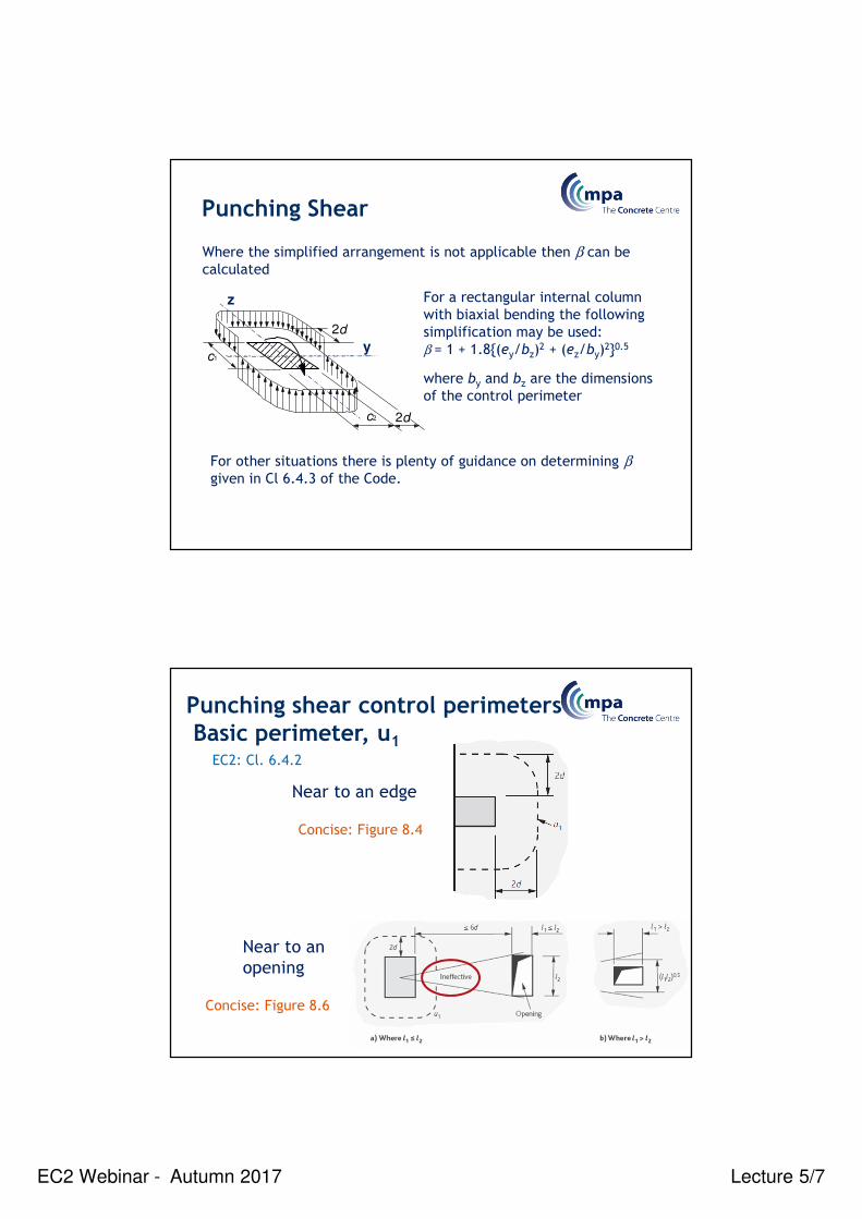
For a rectangular internal column
with biaxial bending the following
simplification may be used:
β = 1 + 1.8{(ey/bz)2 + (ez/by)
2}0.5
where by and bz are the dimensions
of the control perimeter
For other situations there is plenty of guidance on determining βgiven in Cl 6.4.3 of the Code.
Where the simplified arrangement is not applicable then β can be
calculated
c1
c2
2d
2d
y
z
Punching Shear
Punching shear control perimetersBasic perimeter, u1
Near to an
opening
Near to an edge
Concise: Figure 8.4
Concise: Figure 8.6
EC2: Cl. 6.4.2
EC2 Webinar - Autumn 2017 Lecture 5/8
kd
Outer control
perimeter
Outer perimeter of shear
reinforcement
1.5d (2d if > 2d from
column)
0.75d
0.5dA A
Section A - A
0.75d
0.5d
Outer control
perimeter
kd
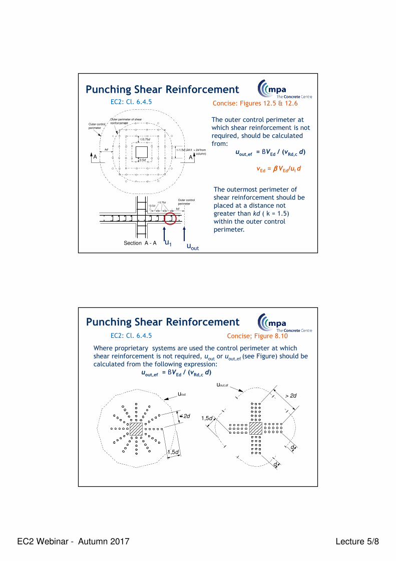
The outer control perimeter at
which shear reinforcement is not
required, should be calculated
from:
uout,ef = βVEd / (vRd,c d)
The outermost perimeter of
shear reinforcement should be
placed at a distance not
greater than kd ( k = 1.5)
within the outer control
perimeter.
Punching Shear Reinforcement EC2: Cl. 6.4.5 Concise: Figures 12.5 & 12.6
u1 uout
vEd = β β β β VEd/ui d
1,5d
2d
d
d
> 2d
1,5d
uout
uout,ef
Where proprietary systems are used the control perimeter at which
shear reinforcement is not required, uout or uout,ef (see Figure) should be
calculated from the following expression:
uout,ef = βVEd / (vRd,c d)
Punching Shear ReinforcementEC2: Cl. 6.4.5 Concise; Figure 8.10

EC2 Webinar - Autumn 2017 Lecture 5/9
EC 2: Concise:
Where shear reinforcement is required it should be calculated in
accordance with the following expression:
vRd,cs = 0.75 vRd,c + 1.5 (d/sr) Asw fywd,ef (1/(u1d)) sinα (6.52)
Asw = area of shear reinforcement in each perimeter around the col.
sr = radial spacing of layers of shear reinforcement
α = angle between the shear reinforcement and the plane of slab
fywd,ef = effective design strength of the punching shear reinforcement,
= 250 + 0.25 d ≤ fywd (MPa.)
d = mean effective depth of the slabs (mm)
Vv v
u dEd
Ed Rd,max
0
β= ≤ = 0.5 ν fcdMax. shear stress at column face,
Punching Shear Reinforcement Cl. 6.4.5, Equ 6.52 8.5
EC2 Equ 6.53
EC 2: Concise:
Vv v
u dEd
Ed Rd,max
0
β= ≤ = 0.5 ν fcdMax. shear stress at column face,
the u0 perimeter
Punching Shear Reinforcement Cl. 6.4.5 (3), Equ 6.53 8.6
c1 and c2 are illustrated
in Concise Figure 8.5

EC2 Webinar - Autumn 2017 Lecture 5/10
Check vEd ≤ 2 vRdc at basic control perimeter ( NA check)
Note: UK NA says ‘first’ control perimeter, but the paper* on which
this guidance is based says ‘basic’ control perimeter
The minimum area of a link leg (or equivalent), Asw,min, is given by the
following expression:
Asw,min (1.5 sinα + cosα)/(sr st) ≥ (0,08 √(fck))/fyk EC2 equ 9.11
Asw,min ≥ (0,053 sr st √(fck)) /fyk For vertical links
*FRASER, AS & JONES, AEK. Effectiveness of punching shear reinforcement to EN 1992-1-1:2004. The Structural Engineer ,19 May 2009.
Punching Shear Reinforcement
Punching shearWorked example
From Worked Examples to EC2: Volume 1
Example 3.4.10

EC2 Webinar - Autumn 2017 Lecture 5/11
Punching shear at column C2
• At C2 the ultimate column reaction is 1204.8 kN
• Effective depths are 260mm & 240mm
• Reinforcement: ρly = 0.0085, ρlz = 0.0048
Design information
400 mm Square
Column
300 mm flat slab
C30/37 concrete
Punching shear
uoutu1
u0
2d
A few definitions:
EC2 Webinar - Autumn 2017 Lecture 5/12
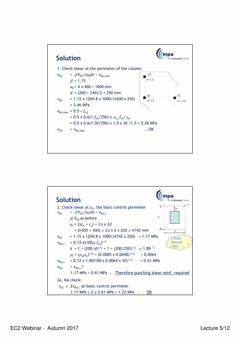
Solution
1. Check shear at the perimeter of the column
vEd = β VEd/(u0d) < vRd,max
β = 1.15
u0= 4 x 400 = 1600 mm
d = (260 + 240)/2 = 250 mm
vEd = 1.15 x 1204.8 x 1000/(1600 x 250)
= 3.46 MPa
vRd,max = 0.5 ν fcd
= 0.5 x 0.6(1-fck/250) x αcc fck/γm
= 0.5 x 0.6(1-30/250) x 1.0 x 30 /1.5 = 5.28 MPa
vEd < vRd,max ...OK
β = 1,4
β = 1,5
β = 1,15
C
B A
Solution2. Check shear at u1, the basic control perimeter
vEd = β VEd/(u1d) < vRd,c
β, VEd as before
u1= 2(cz + cy) + 2π x 2d
= 2(400 + 400) + 2π x 2 x 250 = 4742 mm
vEd = 1.15 x 1204.8 x 1000/(4742 x 250) = 1.17 MPa
vRd,c = 0.12 k(100ρl fck)1/3
k = 1 + (200/d)1/2 = 1 + (200/250)1/2 = 1.89
ρl = (ρlyρlx)1/2 = (0.0085 x 0.0048) 1/2 = 0.0064
vRd,c = 0.12 x 1.89(100 x 0.0064 x 30)1/3 = 0.61 MPa
vEd > vRd,c ?
1.17 MPa > 0.61 MPa ... Therefore punching shear reinf. required
2a. NA check:
vEd ≤ 2vRd,c at basic control perimeter
1.17 MPa ≤ 2 x 0.61 MPa = 1.22 MPa - OK
ρ from
flexural
calcs

EC2 Webinar - Autumn 2017 Lecture 5/13
Solution
3. Perimeter at which punching shear no longer required
uout = β VEd/(dvRd,c)
= 1.15 x 1204.8 x 1000/(250 x 0.61)
= 9085 mm
Rearrange: uout = 2(cx + cy) + 2π rout
rout = (uout - 2(cx + cy))/(2π)
= (9085 – 1600)/(2π) = 1191 mm
Position of outer perimeter of reinforcement from column face:
r = 1191 – 1.5 x 250 = 816 mm
Maximum radial spacing of reinforcement:
sr,max = 0.75 x 250 = 187 mm, say 175 mm
Solution
4. Area of reinforcement
Asw ≥ (vEd – 0.75vRd,c)sru1/(1.5fywd,ef)
fywd,ef = (250 + 0.25d) = 312 MPa
Asw ≥ (1.17 – 0.75 x 0.61) x 175 x 4741/(1.5 x 312)
≥ 1263 mm2/perim.
Minimum area of a link leg:
Asw,min ≥ (0.053 sr st √(fck)) /fyk = 0.053 x 175 x 350 x √30 / 500
≥ 36 mm2
1H10 is 78.5 mm2 dia.
16H10 = 1256 mm2 / per perim
See layout on next slide
could use H8s (50 mm2) but
would need 26 per perimeter So
use H10s (same price as H8s!)

EC2 Webinar - Autumn 2017 Lecture 5/14
Solution
Detailing - Solid slabs

EC2 Webinar - Autumn 2017 Lecture 5/15
• Generally: as for beams.
• Where partial fixity exists, but not taken into account in design:
Internal supports: As,top ≥ 0,25As for Mmax in adjacent span
End supports: As,top ≥ 0,15As for Mmax in adjacent span
• This top reinforcement should extend ≥ 0,2 adjacent span
≥ 2h
h
• Reinforcement at free edges should include ‘u’ bars and
longitudinal bars
Detailing – Solid slabs
Rules for one-way and two-way solid slabs
EC2: Cl. 9.3
• Secondary reinforcement 20% of principal reinforcement
in one-way slabs
Flat Slab Design

EC2 Webinar - Autumn 2017 Lecture 5/16
Flat Slab Design - Contents
Flat slabs - Introduction
EC2 particular rules for flat slabs
Initial sizing
Analysis methods - BM’s and Shear Force
Design constraints
– Punching shear
– Deflection
– Moment transfer from slab to column
What are flat slabs?
• Solid concrete floors of constant thickness
• They have flat soffits
Flat Slabs - Introduction

EC2 Webinar - Autumn 2017 Lecture 5/17
Waffle Slab
Drop Panel
Column Head
Flat Slabs - Introduction
Flat Slabs - Introduction
1. COBIAX
2. BUBBLEDECK
VOIDED SLABS

EC2 Webinar - Autumn 2017 Lecture 5/18
What is the shear resistance governed by the crushing of
compression struts?
Poll Q1:Shear resistance of a beam section
a. VEd
b. VRd,c
c. VRd,max
d. VRd,s
Particular rules for flat slabs
EC2 sections relevant to Flat Slabs:
• Section 6 Ultimate Limit States
– cl 6.4 Punching (shear) & PD 6687 cl 2.16, 2.17 & 2.1.8
• Section 9 Detailing of members and particular rules
– Cl 9.4 Flat slabs
9.4.1 Slab at internal columns
9.4.2 Slab at edge and corner columns
9.4.3 Punching shear reinforcement
• Annex I (Informative) Analysis of flat slabs and shear walls
I.1 Flat Slabs
I.1.1 General
I.1.2 Equivalent frame analysis
I.1.3 Irregular column layout
The Concrete Society, Technical Report 64 - Guide to the
Design and Construction of Reinforced Concrete Flat Slabs

EC2 Webinar - Autumn 2017 Lecture 5/19
EC2: Figure I.1 Concise Figure 5.11
Column strip
Middle strip
Column strip
Column strip Middle strip Column strip
Particular rules for flat slabs
Distribution of moments
Distribution of moments
EC2: Table I.1 Concise: Table 5.2
Particular rules for flat slabs

EC2 Webinar - Autumn 2017 Lecture 5/20
• Arrangement of reinforcement should reflect behaviour
under working conditions.
• At internal columns 0.5At should be placed in a width =
0.25 × panel width.
• At least two bottom bars should pass through internal
columns in each orthogonal directions.
Particular rules for flat slabs
EC2: Cl. 9.4 Concise: 12.4.1
• Design reinforcement at edge and corner reinforcement
should be placed within be
cz
cy
y
be = cz + y
A
cz
cyy
A
be = z + y/2
z
A
Particular rules for flat slabsEC2: Figure 9.9, I.1.2(5) Concise Figure 5.12
• The maximum moment that can be transferred from the
slab to the column should be limited to 0.17bed2fck

EC2 Webinar - Autumn 2017 Lecture 5/21
Edge and corner columns have limited
capacity to transfer moments from slab –
redistribution may be necessary
Moment transfer
Rebar arrangement
Figure 47
Figure 8
3 methods:
1. Simple span to depth table
2. Use Economic Concrete Frame Elements
Imposed Load, Qk (kN/m2) 2.5 5 7.5 10
Multiple Span 28 26 25 23
Initial sizing

EC2 Webinar - Autumn 2017 Lecture 5/22
3 methods:
1. Simple span to depth table
2. Use Economic Concrete Frame Elements
3. Use Concept.xls
Initial sizing
Initial sizing

EC2 Webinar - Autumn 2017 Lecture 5/23
8m
Initial sizing
Equivalent frame method
• Elastic Plane Frame – Equivalent Frame Method, Annex I
• Tabular Method - Equivalent Frame Method, Annex I
• Yield Line
– Plastic method of design
• Finite Element Analysis
– Elastic method
– Elasto plastic
Analysis Methods

EC2 Webinar - Autumn 2017 Lecture 5/24
Elastic Plane Frame – Equivalent Frame Method, Annex I
• Apply in both directions – Y and Z
• Method of Analysis for Bending Moments & SF’s
• Equivalent Frame - the Beams are the Slab width
• Kslab = use full panel width for vertical loads.
• Kslab = use 40% panel width for horizontal loads. Annex
I.1.2.(1)
Analysis Methods
Analysis Methods
Load cases
NA – can use single load case provided:
• Variable load ≤ 1.25 x Permanent load
• Variable load ≤ 5.0 kN/m2
Condition of using single load case is that Support BM’s should be
reduced by 20% except at cantilever supports
Limitation of negative
moments, N1 and N2
Mt,max

EC2 Webinar - Autumn 2017 Lecture 5/25
TR 64 – Figure 14
Reduction in maximum hogging moment
at columns
Analysis Methods
≥ nl2(l1-2hc/3)2/8
Analysis Methods – Equi Frame
Distribution of Design Bending Moments, Annex I
Table I.1 Column Strip Middle Strip
Negative 60 - 80% 40 - 20%
Positive 50 - 70% 50 - 30%
At = Reinforcement area to resist full negative moment. Cl 9.4.1

EC2 Webinar - Autumn 2017 Lecture 5/26
Analysis Methods – Equi Frame
400 mm2/m
100 mm2/m
100 mm2/m
200 mm2/m
200 mm2/m
Distribution of Design Bending Moments - Example
Table I.1 Column Strip Middle Strip
Negative 75% 25%
At = Reinforcement area to resist full negative moment. Cl 9.4.1
= 1600 mm2
Column strip = 1200 mm2 Middle strip = 400 mm2
Equivalent frame method

EC2 Webinar - Autumn 2017 Lecture 5/27
Equivalent frame method
Equivalent frame method - Elastic Plane Frame
• Computer software normally used to assess bending moments and
shear forces
• Design for full load in both directions
• RC spreadsheet TCC33.xls will carry out the analysis and design
Analysis Methods

EC2 Webinar - Autumn 2017 Lecture 5/28
e.g. use coefficients from Concise Tables 15.2 to determine bending
moments and shear forces. BM = coeff x n x span2 SF = coeff x n x span
• Design for full load in both directions
• Frame lateral stability must not be dependent on slab-col connections
• There must be at least three approx equal spans.
• Note: No column BM’s given in table.
Analysis Methods - Tabular Method
A little more accurate:
– Suitable for regular
grids and spans of
similar length
– Design for full load
in both directions
– Suitable for 2-span
– Note: No column
BM’s given in table
Concise Table 15.3
Analysis Methods - Tabular Method

EC2 Webinar - Autumn 2017 Lecture 5/29
Yield Line Method
Equilibrium and work methods.
‘work method’
External energy expended by
the displacement of loads
Internal energy dissipated by
the yield lines rotating
=
Analysis Methods
Yield Line Method
Suitable for:
◦ irregular layouts
◦ Slabs supported on 2 or 3
edges only
Detailed guidance and numerous
worked examples contained in:
Practical Yield Line Design
Deflection design to simplified rules
Analysis Methods

EC2 Webinar - Autumn 2017 Lecture 5/30
Finite Element Method
Suitable for:
◦ irregular layouts
◦ slabs with service openings
◦ post tensioned design
(specialist software)
Common pitfalls:
◦ Use long term E-values (typically 1/3 to 1/2 short term value)
◦ Use cracked section properties (typically 1/2 gross
properties) by adjusting E-value to suit
◦ Therefore appropriate E-values are usually 4 to 8 kN/mm2
Analysis Methods
Finite Element - Design moments

EC2 Webinar - Autumn 2017 Lecture 5/31
Punching Shear - EC2: cl 6.4 and cl 9.4.3
• Traditional links
• Shear Rails
Design Constraints
Shape 51
Shape 22
Shape 47
Deflection:
Wherever possible use the span/effective depth ratios, cl 7.4.2 (2)
Span is based on the longer span and the K factor is 1.2
Reduction factor for brittle finishes for spans greater than 8.5m
Design Constraints

EC2 Webinar - Autumn 2017 Lecture 5/32
Moment Transfer from slab to column:
Edge and corner columns have limited capacity to transfer moments
from slab – redistribution may be necessary (Annex I.1.2 (5), EC2 cl
9.4.2 & TR 64)
Mt, max = 0.17 be d2 fck
Design Constraints
Effective
width, be.
Flat slab worked example
Flexure
From Worked Examples to EC2: Volume 1
Example 3.4.

EC2 Webinar - Autumn 2017 Lecture 5/33
Introduction to worked example
This is example 3.4
of Worked examples
to Eurocode 2:
Volume 1.
• Nominal cover = 30mm
Design information
Design strip along grid line C
Assume strip is 6 m wide
Slab is 300 mm deep
Determine the reinforcement
– slab along grid line C.

EC2 Webinar - Autumn 2017 Lecture 5/34
Flat slab
Worked example
For the previous flat
slab example determine:
• Sagging reinforcement
in the span 1-2
and
• Hogging reinforcement
at support 29600
Analysis
gk = 0.30 x 25 + 1.0 = 8.5 kN/m2
qk = 4.0 kN/m2
n = 1.25 x 8.5 + 1.5 x 4.0 = 16.6 kN/m2
Analysis: using coefficients from Concise Table 15.3:(Adjacent spans are 9.6 and 8.6 m. 8.6/9.6 = 0.89: i.e. > 85% so
using coefficients is appropriate.)
Effective span = 9.6 – 2 x 0.4/2 + 2 x 0.3/2 = 9.5 m
In panel: sagging moment,
MEd = (1.25 x 8.5 x 0.09 + 1.5 x 4 x0.100) x 6.0 x 9.52 = 842.7 kNm
Actions:
Along support 2: hogging moment
MEd = 16.6 x 0.106 x 6.0 x 9.52 = 952.8 kNm
NB. Exp(6.10b) used!
See Note to Concise Table 15.3 for support of 2-span slab
EC2 Webinar - Autumn 2017 Lecture 5/35
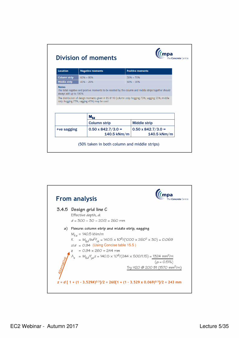
Division of moments
MMMMEdEdEdEd
Column strip Middle strip
+ve sagging 0.50 x 842.7/3.0 =
140.5 kNm/m
0.50 x 842.7/3.0 =
140.5 kNm/m
(50% taken in both column and middle strips)
From analysis
(Using Concise table 15.5 )
z = d [ 1 + (1 - 3.529K)0.5]/2 = 260[1 + (1 – 3.529 x 0.069)0.5]/2 = 243 mm

EC2 Webinar - Autumn 2017 Lecture 5/36
Hogging Moments
(Using Concise Table 15.5)
z = d [ 1 + (1 - 3.529K)0.5]/2 = 260[1 + (1 – 3.529 x 0.109)0.5]/2 = 232 mm
MMMMEdEdEdEd
Column strip Middle strip
-ve hogging 0.700.700.700.70 x 952.8/3.0 =
222.3 kNm/m
0.300.300.300.30 x 952.8/3.0 =
95.3 kNm/m
(70% taken in column strip and 30% in middle strip)
Hogging Moments
(Using Concise table 15.5 )
z = d [ 1 + (1 - 3.529K)0.5]/2 = 260[1 + (1 – 3.529 x 0.047)0.5]/2
= 248 mm ≤ 0.95d ≤ 247 mm
= 247
0.047

EC2 Webinar - Autumn 2017 Lecture 5/37
Reinforcement distribution
Total area of reinforcement:
As,tot = 2213 x 3 + 887 x 3 = 9300 mm2
50% As,tot = 9300/2 = 4650 mm2
This is spread over a width of 1.5 m
As,req = 4650/1.5 = 3100 mm2/m
Use H20 @ 100 ctrs T(3140 mm2/m)
Remaining column strip:
As,req = (2213 x 3 – 4650)/1.5 = 1326 mm2/m
Use H20 @ 200 ctrs T(1570 mm2/m)
Or use H16 @ 100 ctrs(1540 mm2/m)
Middle strip: As,req = 887 mm2/m
Use H16 @ 200 ctrs T(1010mm2/m)
Or use H12 @ 100 ctrs (1130mm2/m)
Exercise
Lecture 5
Check an edge column for punching shear

EC2 Webinar - Autumn 2017 Lecture 5/38
Punching shearExercise
Based on the flat slab in section 3.4 of
Worked Examples to EC2: Volume 1
Punching shear at column C1
• At C1 the ultimate column reaction is 609.5 kN
• Effective depths are 260mm & 240mm
• Reinforcement: ρly = 0.0080, ρlz = 0.0069
Design information
400 mm Square
Column
300 mm flat slab
C30/37 concrete

EC2 Webinar - Autumn 2017 Lecture 5/39
Punching shear exerciseFor the previous flat slab
example:
a) Check the shear stress at
the perimeter of column
C1. The u0 perimeter.
b) Check the shear stress at
the basic perimeter, u1.
c) Determine the distance
of the uout perimeter
from the face of column
C1.
d) Determine the area of
shear reinforcement
required on a perimeter.
i.e. find Asw for the u1
perimeter.
9600
C1
Working space