Airfoile Noise Optimization
10
Airfoil optimization for noise emission problem and aerodynamic performance criterion on small scale wind turbines Tuhfe Göçmen a, * , Barıs ¸ Özerdem a, b a Department of Mechanical Engineering, _ Izmir Institute of Technology, Gülbahçe, 35430 Urla-Izmir, Turkey b Department of Energy Systems Engineering, Bahcesehir University, 34353 Besiktas-Istanbul, Turkey article info Article history: Received 13 September 2011 Received in revised form 17 May 2012 Accepted 18 May 2012 Available online 18 June 2012 Keywords: Small scale wind turbine Noise emission Aerodynamic performance Aero-acoustics Airfoil optimization abstract Noise emission is one of the major concerns in wind turbine industry and especially for small scale wind turbines, which are mostly erected to the urban areas; the concern is turning into a problem. This paper focuses on the optimization of six airfoils which are widely used on small scale wind turbines in terms of the noise emission and performance criteria and the numerical computations are performed for a typical 10 kW wind turbine. The main purpose of this optimization process is to decrease the noise emission levels while increasing the aerodynamic performance of a small scale wind turbine by adjusting the shape of the airfoil. The sources of the broadband noise emission are defined and their dominancy is investigated with respect to the operating conditions. While redesigning, together with the principals of reducing the airfoil self-noise, the aerodynamic prospects of increasing the performance have been taken into account. The codes which are based on aero-acoustic empirical models and a collection of well- known aerodynamic functions are used in this study. The results obtained from the numerical analysis of the optimization process have shown that, the considered commercial airfoils for small scale wind turbines are improved in terms of aero-acoustics and aerodynamics. The pressure sides of the baseline airfoils have been manipulated together with the trailing edge and redesigned airfoils have lower levels of noise emission and higher lift to drag ratios. Ó 2012 Elsevier Ltd. All rights reserved. 1. Introduction The technological research on sustainable energy has been propagating and accelerating all around the world as a result of the energy politics gained today. In this context, the wind power is playing an important role contributing to this development. The small scale wind turbines seem to contribute a lot to this devel- opment, especially in Turkey, because of its potential and the recent legal arrangement done on this subject. However, the wind turbine noise is one of the major obstacles on the widespread use of wind power. The main sources of wind turbine noise may be divided into two: mechanical noise which includes the noise from the fans, generator, gear box etc., and the aerodynamic noise which is orig- inated from the interaction between the rotor and the wind. Nowadays the mechanical noise is mostly handled; therefore the main engineering effort is being made on the subject of aero- dynamic noise research [1]. There are five self-noise mechanisms on an airfoil, aerodynamically: Turbulent boundary layer trailing edge noise, separation e stall noise, laminar boundary layer vortex shedding noise, trailing edge bluntness e vortex shedding noise and turbulent inflow noise [2]. Some early researchers were considering the tip vortex formation as the fifth noise mechanism [3]. Turbulent boundary layer trailing edge noise; is the noise that is occurred due to the formation of turbulence and wakes around the trailing edge of the airfoil. Separation e stall noise exists where the flow is separated around the airfoil. Laminar boundary layer vortex shedding noise occurs when a laminar boundary layer exists on any side of an airfoil. Trailing edge bluntness e vortex shedding noise is the noise that is formed due to the vortex shedding caused by the bluntness of the trailing edge. Turbulent inflow noise is due to the characteristics of the incoming flow. The optimization process, which is based on the geometrical changes done on the airfoils, has been applied to profiles of FX 63- 137, S822, S834, SD2030, SG6043 and SH3055. They are chosen to be optimized since they may be considered to be in widely use in small scale wind turbines [4]. The optimization process starts with the prediction of noise generation and the results of such analysis can be found in the studies of Kim et al. [5] in which turbulent inflow and turbulent * Corresponding author. Tel.: þ90 232 7506789; fax: þ90 232 7506701. E-mail address: [email protected] (T. Göçmen). Contents lists available at SciVerse ScienceDirect Energy journal homepage: www.elsevier.com/locate/energy 0360-5442/$ e see front matter Ó 2012 Elsevier Ltd. All rights reserved. http://dx.doi.org/10.1016/j.energy.2012.05.036 Energy 46 (2012) 62e71
-
Upload
luca-anzidei -
Category
Documents
-
view
227 -
download
0
description
Airfoile Noise Optimization
Transcript of Airfoile Noise Optimization

at SciVerse ScienceDirect
Energy 46 (2012) 62e71
Contents lists available
Energy
journal homepage: www.elsevier .com/locate/energy
Airfoil optimization for noise emission problem and aerodynamic performancecriterion on small scale wind turbines
Tuhfe Göçmen a,*, Barıs Özerdem a,b
aDepartment of Mechanical Engineering, _Izmir Institute of Technology, Gülbahçe, 35430 Urla-Izmir, TurkeybDepartment of Energy Systems Engineering, Bahcesehir University, 34353 Besiktas-Istanbul, Turkey
a r t i c l e i n f o
Article history:Received 13 September 2011Received in revised form17 May 2012Accepted 18 May 2012Available online 18 June 2012
Keywords:Small scale wind turbineNoise emissionAerodynamic performanceAero-acousticsAirfoil optimization
* Corresponding author. Tel.: þ90 232 7506789; faE-mail address: [email protected] (T. Göçm
0360-5442/$ e see front matter � 2012 Elsevier Ltd.http://dx.doi.org/10.1016/j.energy.2012.05.036
a b s t r a c t
Noise emission is one of the major concerns in wind turbine industry and especially for small scale windturbines, which are mostly erected to the urban areas; the concern is turning into a problem. This paperfocuses on the optimization of six airfoils which are widely used on small scale wind turbines in terms ofthe noise emission and performance criteria and the numerical computations are performed for a typical10 kW wind turbine. The main purpose of this optimization process is to decrease the noise emissionlevels while increasing the aerodynamic performance of a small scale wind turbine by adjusting theshape of the airfoil. The sources of the broadband noise emission are defined and their dominancy isinvestigated with respect to the operating conditions. While redesigning, together with the principals ofreducing the airfoil self-noise, the aerodynamic prospects of increasing the performance have been takeninto account. The codes which are based on aero-acoustic empirical models and a collection of well-known aerodynamic functions are used in this study. The results obtained from the numerical analysisof the optimization process have shown that, the considered commercial airfoils for small scale windturbines are improved in terms of aero-acoustics and aerodynamics. The pressure sides of the baselineairfoils have been manipulated together with the trailing edge and redesigned airfoils have lower levelsof noise emission and higher lift to drag ratios.
� 2012 Elsevier Ltd. All rights reserved.
1. Introduction
The technological research on sustainable energy has beenpropagating and accelerating all around the world as a result of theenergy politics gained today. In this context, the wind power isplaying an important role contributing to this development. Thesmall scale wind turbines seem to contribute a lot to this devel-opment, especially in Turkey, because of its potential and the recentlegal arrangement done on this subject. However, the wind turbinenoise is one of the major obstacles on the widespread use of windpower. The main sources of wind turbine noise may be divided intotwo: mechanical noise which includes the noise from the fans,generator, gear box etc., and the aerodynamic noise which is orig-inated from the interaction between the rotor and the wind.Nowadays the mechanical noise is mostly handled; therefore themain engineering effort is being made on the subject of aero-dynamic noise research [1]. There are five self-noise mechanismson an airfoil, aerodynamically: Turbulent boundary layer trailing
x: þ90 232 7506701.en).
All rights reserved.
edge noise, separation e stall noise, laminar boundary layer vortexshedding noise, trailing edge bluntness e vortex shedding noiseand turbulent inflow noise [2]. Some early researchers wereconsidering the tip vortex formation as the fifth noise mechanism[3].
Turbulent boundary layer trailing edge noise; is the noise that isoccurred due to the formation of turbulence and wakes around thetrailing edge of the airfoil. Separation e stall noise exists where theflow is separated around the airfoil. Laminar boundary layer vortexshedding noise occurs when a laminar boundary layer exists on anyside of an airfoil. Trailing edge bluntness e vortex shedding noise isthe noise that is formed due to the vortex shedding caused by thebluntness of the trailing edge. Turbulent inflow noise is due to thecharacteristics of the incoming flow.
The optimization process, which is based on the geometricalchanges done on the airfoils, has been applied to profiles of FX 63-137, S822, S834, SD2030, SG6043 and SH3055. They are chosen tobe optimized since they may be considered to be in widely use insmall scale wind turbines [4].
The optimization process starts with the prediction of noisegeneration and the results of such analysis can be found in thestudies of Kim et al. [5] in which turbulent inflow and turbulent
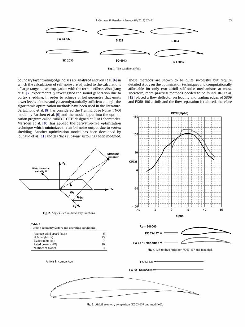
Fig. 1. The baseline airfoils.
T. Göçmen, B. Özerdem / Energy 46 (2012) 62e71 63
boundary layer trailing edge noises are analyzed and Son et al. [6] inwhich the calculations of self-noise are adjusted to the calculationsof large range noise propagation with the terrain effects. Also, Jianget al. [7] experimentally investigated the sound generation due tovortex shedding. In order to achieve airfoil geometry that emitslower levels of noise and yet aerodynamically sufficient enough, thealgorithmic optimization methods have been used in the literature.Bertagnolio et al. [8] has considered the Trailing Edge Noise (TNO)model by Parchen et al. [9] and the model is put into the optimi-zation program called “AIRFOILOPT” designed at Risø Laboratories.Marsden et al. [10] has applied the derivative-free optimizationtechnique which minimizes the airfoil noise output due to vortexshedding. Another optimization model has been developed byJouhaud et al. [11] and 2D Naca subsonic airfoil has been modified.
Fig. 2. Angles used in directivity functions.
Table 1Turbine geometry factors and operating conditions.
Average wind speed (m/s) 6Hub height (m) 25Blade radius (m) 7Rated power (kW) 10Number of blades 3
Fig. 3. Airfoil geometry compariso
Those methods are shown to be quite successful but requiredetailed study on the optimization techniques and computationallyaffordable for only two airfoil self-noise mechanisms at most.Therefore, more practical methods needed to be found. Bai et al.[12] placed a flow deflector on leading and trailing edges of S809and FX60-100 airfoils and the flow separation is reduced, therefore
n (FX 63-137 and modified).
Fig. 4. Lift to drag ratios for FX 63-137 and modified.

Fig. 5. SPL spectra for FX 63-137 and modified.
T. Göçmen, B. Özerdem / Energy 46 (2012) 62e7164
noise is decreased where lift to drag ratio is increased. A morepractical airfoil shape optimization has been done by decreasingthe maximum thickness of the baseline airfoil basically [13]. Thisstudy is based on the geometrical approaches around the pressureside and the trailing edge of the profile. Those geometricalapproaches include thinner trailing edge and engraved surface inthe lower part of the airfoil and all five mechanisms of airfoil self-noise have been taken into account. With this study, it was plannedto reveal the basic geometrical specifications that an airfoil shouldhave in order to reduce small scale wind turbine noise emissionlevels and six airfoils have been studied as examples. It is concludedthat considered commercially available airfoils can be improved toemit lower self-noise and have better aerodynamic performances.
2. Material and method
The XFOIL code is used to predict the aerodynamic perfor-mances of the airfoils [14] which are shown in Fig. 1. The linearvorticity stream function panel method is used in this numericalapproach and 2D flow field is constructed by three components:free stream flow, airfoil surface vortex sheet, and source sheet. Thedomain which is composed of airfoil contour and the wake is dis-cretized into panels and each panel is assumed to have a linearvorticity profile and constant source strength. According to thestudy done by Hoogedoorn et al. [15], XFOIL has been validatedespecially for high Reynolds numbers which is the case of this study
Fig. 6. Airfoil geometry compar
and is said to have capability to perform separation and stallcalculations accurately.
While comparing the aerodynamic performances, according tothe study edited by Spera et al. [16] the ratio of lift coefficient todrag coefficient is considered as the most important criterion.
The NAFNoise code [20] is used for the prediction of the airfoilself-noise and the numerical algorithm is based on the semi-empirical models that are achieved by Brooks et al. [3], for thefirst four noise sources. For the last noise source that is listed as theturbulent inflow noise, the semi-empirical formula obtained byAmiet et al. [17] is taken into account. The validation of NAFNoise isstudied by Moriarty et al. [18] for Mach number of 0.2 which is thecase of this study.
2.1. Semi-empirical noise models
2.1.1. Turbulent boundary layer trailing edge noiseThis is the first and perhaps the most common airfoil self - noise
source especially for high Reynolds numbers. Based on the studiesdone by Brooks et al. [3] the turbulent boundary layer trailing edgenoise along the pressure side of the airfoil is modeled as;
SPLp ¼ 10log
d*pM
5LDh
r2e
!þ A
�StpSt1
�þ ðK1 � 3Þ þ DK1 (1)
And for the suction side;
ison (S822 and modified).

Fig. 7. Lift to drag ratios for S822 and modified.
T. Göçmen, B. Özerdem / Energy 46 (2012) 62e71 65
SPLs ¼ 10log
d*sM
5LDh
r2e
!þ A
�StsSt1
�þ ðK1 � 3Þ (2)
Fig. 8. SPL spectra for S
where d* ¼ d*(a, Rec) is the boundary layer displacement thickness,based on a, the angle of attack, and Rec, the Reynolds number basedon chord. The subscript p refers to the pressure side and s to thesuction side of the airfoil. Other parameters in Eqs. (1) and (2) are L,the span of the airfoil section; re, the effective observer distance;and A, an empirical spectral shape based on the Strouhal number,St ¼ (fd*/U), where f is the frequency, and U is the local meanvelocity. Three other empirical relations are also used,St1 ¼ 0.02M�0.6, K1 ¼ K1 (Rec), and DK1 ¼ DK1 (a, Red*). Also, Dh, thedirectivity function is defined in the equations since it is a correc-tion factor considering the distance between source and theobserver and therefore the Doppler effect and it may be describedas [1];
DhðQeFeÞz2sin2
�1=2Qe
�sin2 Fe
ð1þMcos QeÞð1þ ðM �McÞcos QeÞ2(3)
where M is the Mach number for airfoil section and Mc is theconvective Mach number and Qe and Fe are the directivity angleswhich are determined by Fig. 2.
2.1.2. Separation e stall noiseFor an airfoil, as the angle of attack, a, increases within its bound-
aries, the separation around the suction side of the profile increasesand that situation becomes more dominant on producing the noise.The semi e empirical formula of separation e stall noise, SPLa is verysimilar to Eq. (2) except that it has a remarkable dependency on a.
The resulting scalingmodel for turbulent boundary layer trailingedge noise with noise due to separation and stall characteristics isthen [1];
SPLTBL�TE ¼ 10log�10SPLp=10 þ 10SPLs=10 þ 10SPLa=10
�(4)
2.1.3. Laminar boundary layer vortex shedding noiseSince the characteristic of that type of noise is feedback ampli-
fication, it is tonal and therefore is not disturbing for larger scalewind turbines with higher Reynolds number. However, it is stilla major concern for small scale ones which are the subject of this
822 and modified.

Fig. 9. Airfoil geometry comparison (S834 and modified).
Fig. 10. Lift to drag ratios for S834 and modified.
T. Göçmen, B. Özerdem / Energy 46 (2012) 62e7166
study. The laminar boundary layer vortex shedding noise isdescribed by Brooks et al. [3] as;
SPLLBL�VS ¼ 10log
d*pM
5LDh
r2e
!þ G1
St0
St0peak
!þ G2
�Rec
ðRecÞ0
�
þ G3ðaÞ(5)
where most of the variables are already defined in Eq. (1) Otherthan those, which are G1, G2, and G3 are empirical functions, St0 isthe Strouhal number based on dp, St0peak ¼ St0peak(Rec) and it is thepeak Strouhal number and (Rec)o is a reference Reynolds numberdepending on the angle of attack.
2.1.4. Trailing edge bluntness e vortex shedding noiseSince this source of noise emission from wind turbines is
directly related with the airfoil geometry, the model includes somegeometry-defined parameters. Trailing edge bluntness e vortexshedding noise is described as;
SPLTEB�VS ¼ 10log
d*pM
5LDh
r2e
!þ G4
0@ h
d*avg;J
1A
þ G5
0@ h
d*avg;J;
St00
St00peak
1A (6)
where h is the trailing edge thickness, d*avg is the averagedisplacement thickness for both sides of the airfoil, J is the solidangle between both airfoil surfaces just upstream of the trailingedge, St00 is the Strouhal number based on h, St00peak ¼ St00peak(h/d
*avg) is
the peak Strouhal number; and G4 and G5 are empirical functions ofthese parameters.
2.1.5. Turbulent inflow noiseThe incoming flow characteristics play an important role in this
type of noise emission from the wind turbines. Different from theprevious four models, this semi e empirical formula is studied byAmiet et al. [17].
SPLInflow ¼ SPLHInflow þ 10log�
LFC1þ LFC
�(7)
SPLHInflow ¼ 10log
r20c
20lL
2r2eM3u2I2
K3�1þ K2
�73
DL
!þ 58:4 (8)
LFC ¼ 10S2MK2b�2 (9)
S2 ¼ 2pK
b2þ 1þ 2:4
K
b2
!�1!�1
(10)
where ro is the air density, co is the speed of sound, l is a turbulencelength scale, u is the meanwind speed, I is the turbulence intensity,
K ¼ pfc/U, is the local wave number, where f is the frequency ofinterest, c is the local airfoil chord length, and U is the local velocityover the airfoil section, DL is a low-frequency directivity function,LFC is a low e frequency correction factor, S is the compressibleSears function; and b2 ¼ 1�M2.
3. Results and discussion
During the optimization process, main idea was to change theshape of the pressure side of the airfoil since it is aerodynamicallycritical. Also the trailing edge of each airfoil has been well studiedsince most of the self-noise is originated from that location. Notethat the calculations are done for a typical 10 kWwind turbinewitha radius of 7 m. The flow characteristics around the airfoils havebeen identified using the studies of Ünveren et al. [19] and thewindspeed is averagely taken to be 6 m/s for a hub height of 25 m. TheReynolds number of that flow is calculated around 3.0 � 105
and Mach number calculation gives a value of 0.02 for an
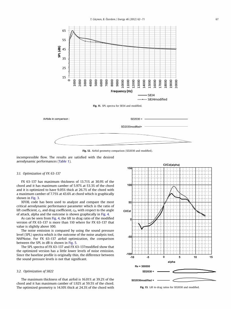
Fig. 11. SPL spectra for S834 and modified.
Fig. 12. Airfoil geometry comparison (SD2030 and modified).
T. Göçmen, B. Özerdem / Energy 46 (2012) 62e71 67
incompressible flow. The results are satisfied with the desiredaerodynamic performances (Table 1).
3.1. Optimization of FX 63-137
FX 63-137 has maximum thickness of 13.71% at 30.9% of thechord and it has maximum camber of 5.97% at 53.3% of the chordand it is optimized to have 9.05% thick at 26.7% of the chord witha maximum camber of 7.75% at 43.6% at chord which is graphicallyshown in Fig. 3.
XFOIL code has been used to analyze and compare the mostcritical aerodynamic performance parameter which is the ratio oflift coefficient, cL, and drag coefficient, cD, with respect to the angleof attack, alpha and the outcome is shown graphically in Fig. 4.
As can be seen from Fig. 4, the lift to drag ratio of the modifiedversion of FX 63-137 is more than 110 where for FX 63-137 thatvalue is slightly above 100.
The noise emission is compared by using the sound pressurelevel (SPL) spectra which is the outcome of the noise analysis tool,NAFNoise. For FX 63-137 airfoil optimization, the comparisonbetween the SPL in dB is shown in Fig. 5.
The SPL spectra of FX 63-137 and FX 63-137modified show thatthe optimized version has a little lower levels of noise emission.Since the baseline profile is originally thin, the difference betweenthe sound pressure levels is not that significant.
Fig. 13. Lift to drag ratios for SD2030 and modified.
3.2. Optimization of S822
The maximum thickness of that airfoil is 16.01% at 39.2% of thechord and it has maximum camber of 1.92% at 59.5% of the chord.The optimized geometry is 14.10% thick at 24.3% of the chord with
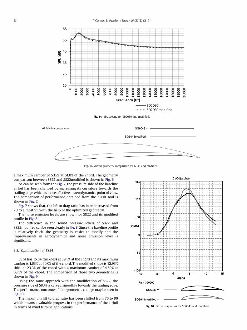
Fig. 14. SPL spectra for SD2030 and modified.
Fig. 15. Airfoil geometry comparison (SG6043 and modified).
Fig. 16. Lift to drag ratios for SG6043 and modified.
T. Göçmen, B. Özerdem / Energy 46 (2012) 62e7168
a maximum camber of 5.15% at 61.0% of the chord. The geometrycomparison between S822 and S822modified is shown in Fig. 6.
As can be seen from the Fig. 7, the pressure side of the baselineairfoil has been changed by increasing its curvature towards thetrailing edgewhich is more effective in aerodynamics point of view.The comparison of performance obtained from the XFOIL tool isshown in Fig. 7.
Fig. 7 shows that, the lift to drag ratio has been increased from70 to almost 95 with the help of the optimized geometry.
The noise emission levels are shown for S822 and its modifiedprofile in Fig. 8.
The difference in the sound pressure levels of S822 andS822modified can be seen clearly in Fig. 8. Since the baseline profileis relatively thick, the geometry is easier to modify and theimprovements in aerodynamics and noise emission level issignificant.
3.3. Optimization of S834
S834 has 15.0% thickness at 39.5% at the chord and its maximumcamber is 1.63% at 60.0% of the chord. The modified shape is 12.93%thick at 23.3% of the chord with a maximum camber of 4.69% at63.1% of the chord. The comparison of those two geometries isshown in Fig. 9.
Using the same approach with the modification of S822, thepressure side of S834 is carved smoothly towards the trailing edge.The performance outcome of that geometric change may be seen inFig. 10.
The maximum lift to drag ratio has been shifted from 70 to 90which means a valuable progress in the performance of the airfoilin terms of wind turbine applications.
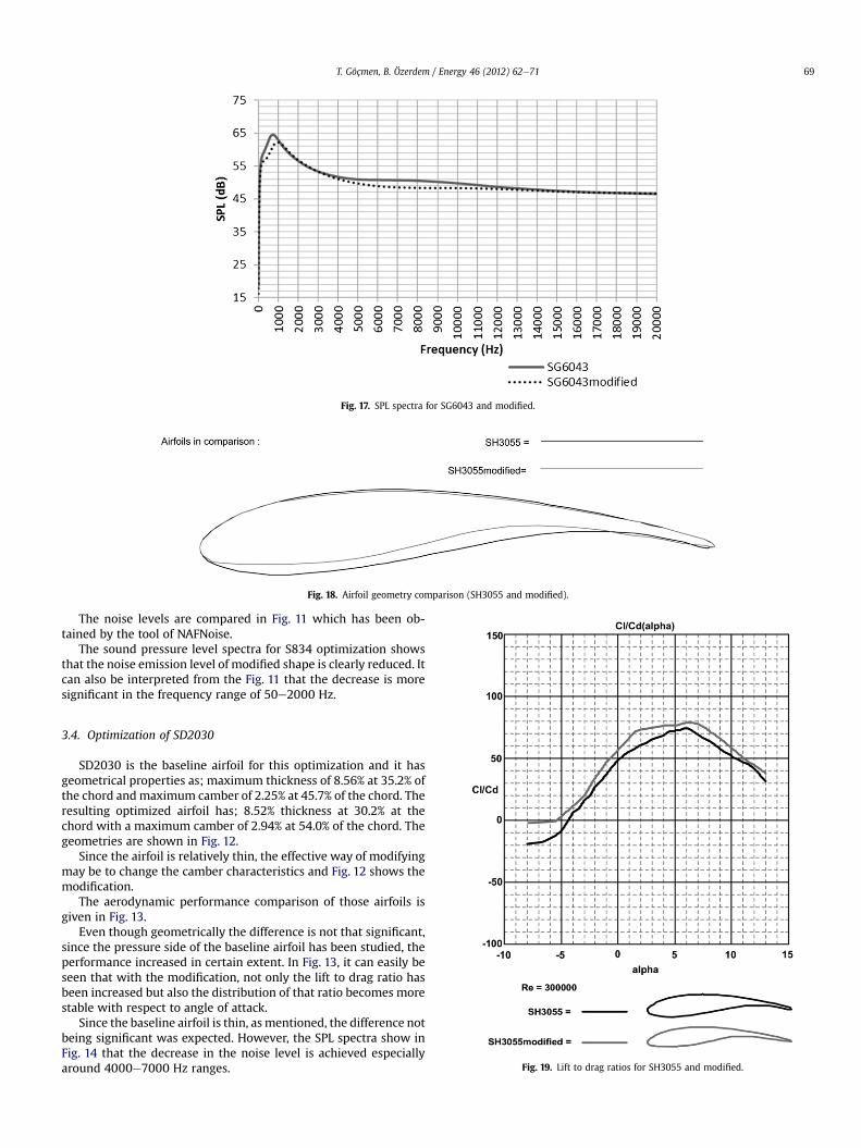
Fig. 17. SPL spectra for SG6043 and modified.
Fig. 18. Airfoil geometry comparison (SH3055 and modified).
T. Göçmen, B. Özerdem / Energy 46 (2012) 62e71 69
The noise levels are compared in Fig. 11 which has been ob-tained by the tool of NAFNoise.
The sound pressure level spectra for S834 optimization showsthat the noise emission level of modified shape is clearly reduced. Itcan also be interpreted from the Fig. 11 that the decrease is moresignificant in the frequency range of 50e2000 Hz.
Fig. 19. Lift to drag ratios for SH3055 and modified.
3.4. Optimization of SD2030
SD2030 is the baseline airfoil for this optimization and it hasgeometrical properties as; maximum thickness of 8.56% at 35.2% ofthe chord andmaximum camber of 2.25% at 45.7% of the chord. Theresulting optimized airfoil has; 8.52% thickness at 30.2% at thechord with a maximum camber of 2.94% at 54.0% of the chord. Thegeometries are shown in Fig. 12.
Since the airfoil is relatively thin, the effective way of modifyingmay be to change the camber characteristics and Fig. 12 shows themodification.
The aerodynamic performance comparison of those airfoils isgiven in Fig. 13.
Even though geometrically the difference is not that significant,since the pressure side of the baseline airfoil has been studied, theperformance increased in certain extent. In Fig. 13, it can easily beseen that with the modification, not only the lift to drag ratio hasbeen increased but also the distribution of that ratio becomes morestable with respect to angle of attack.
Since the baseline airfoil is thin, asmentioned, the difference notbeing significant was expected. However, the SPL spectra show inFig. 14 that the decrease in the noise level is achieved especiallyaround 4000e7000 Hz ranges.

Fig. 20. SPL spectra for SH3055 and modified.
T. Göçmen, B. Özerdem / Energy 46 (2012) 62e7170
3.5. Optimization of SG6043
SG6043 is another relatively thin airfoil used in the small scalewind turbines with a thickness of 10.0% at 32.3% of the chord andmaximum camber of 5.45% at 48.8% of the chord. SG6043modifiedwhich is the optimized airfoil has a maximum thickness of 7.13% at25.9% of the chord and its camber is distributed with a maximumvalue of 6.98% at 46.6% of the chord. They are seen schematically inFig. 15.
The optimization process of SG6043 includes the changes madein thickness and camber distribution, as can be seen in Fig. 15. Theoutcome of this optimized pressure side aerodynamically is shownin Fig. 16.
SG6043modified has higher maximum lift to drag ratio aroundits design angle of attack, adesign. Fig. 16 also shows that the valuesof cL/cD of the optimized shape are below the ones that belong tothe baseline airfoil. However, since corresponding angle of attacksare already in the regionwhere stall occurs, the performance of thewind turbine will be at its minimum regardless to its lift to dragratio. Thus, the optimization may still be considered satisfactory interms of aerodynamic performance.
The airfoil self-noise characteristics of those two profiles aregiven in Fig. 17.
The noise emission levels differ tremendously especially forrelatively lower frequencies because of the fact that the modifiedshape of SG6043 profile has smoother trailing edge and the overallthickness is lower.
3.6. Optimization of SH3055
SH3055 is one of the widely used airfoil in small scale windturbine business and it is really successful in terms of consumersatisfaction. However, this optimization process shows that eventhis profile may be modified to have lower noise emission levelswhile its performance is increased.
The maximum thickness of SH3055 is 15.11% at 25.2% of thechord and the maximum camber of this profile is 5.40% at 62.9% ofthe chord. The modified version, SH3055 modified, is 13.14% thickat 26.5% of the chord where the maximum camber is 6.57% at 57.4%
of the chord. The geometrical comparison of those two airfoils isincluded in Fig. 18.
As can be seen from Fig. 18, especially towards the leading edge,the overall thickness of the baseline airfoil is reduced. The reasonfor that is the trailing edge performance of SH3055 is satisfactoryand no need for further improvements. However, by sharpening thenose section of the profile has improved the flow uniformityaround the airfoil and therefore reduced the additional boundarylayer formation which directly reduces noise and increases theperformance.
The performance criteria of the airfoils mentioned above iscompared in Fig. 19.
The cL/cD distribution of SH3055 modified is not only higher butalso more stable meaning that there is no significant peak pointswhich is important for the turbine to perform at its best in variousangles of attack.
As can be seen from Fig. 20, the noise emission level of SH3055 isalso decreased quite significantly.
4. Conclusion
Airfoil low noise and high performance design optimization hasbeen carried out for a typical three bladed, 10 kW wind turbinewhich has a radius of 7m. In this study, FX 63-137, S822, S834,SD2030, SG6043 and SH3055 which are the most widely usedairfoils on the small scale wind turbine have been studied and eachof them have been developed to have lower noise emission andhigher aerodynamic performance, separately. In order to achievethat goal, the flow analysis tool XFOIL and airfoil self-noise analysistool NAFNoise have been used. While changing the geometry of theairfoils, especially the pressure side and the trailing edge charac-teristics have been modified since they are the most critical loca-tions particularly for aerodynamic and aero-acoustic concerns,respectively. In order to compare those two outcomes of the opti-mization, lift to drag criterion and SPL spectra has been drawn. Thedifference between the baseline and optimized versions of rela-tively thinner airfoils are not seen significantly because thegeometrical changes made on those thin profiles are not allowedto be substantial. However, even for the thin profiles, the
T. Göçmen, B. Özerdem / Energy 46 (2012) 62e71 71
improvement in noise and performance characteristics is clearlyshown. It can be seen that, with the geometrical optimizationapplied, the lift to drag ratios are increased whereas the noiseemission levels are decreased up to 5 dB. Each of the optimizedairfoils has been shown to have better aerodynamic performanceand lower noise emission than their baseline profiles.
Nomenclature
d* boundary layer displacement thickness, ma, alpha the angle of attack, degRec Reynolds number based on chordL span of the airfoil section, mre, effective observer distance, mA empirical spectral shape based on theSt Strouhal numberf frequency, HzU local mean velocity, m/sDh directivity functionM Mach numberMc convective Mach numberQe, Fe directivity anglesSPLa separation e stall noise, dBSPLTBL-TE turbulent boundary layer trailing edge noise, dBSPLp trailing edge noise along the pressure side of the airfoilSPLs trailing edge noise along the suction side of the airfoilSPLLBL-VS laminar boundary layer vortex shedding noise, dBG1, G2, G3empirical functionsSt0 Strouhal number based on dp*St0peak peak Strouhal number(Rec)o reference Reynolds number depending on the angle of
attackSPLTEB-VS trailing edge bluntness e vortex shedding noise, dBh trailing edge thickness, md*avg average displacement thickness for both sides of the
airfoil, mJ solid angle between both airfoil surfaces just upstream of
the trailing edge, degSt00 Strouhal number based on hSt00peak peak Strouhal number based on hG4, G5 empirical functionsSPLInflow turbulent inflow noise, dBro air density, kg/m3
co speed of sound, m/sl turbulence length scale, mu mean wind speed, m/sI turbulence intensity, %K local wave number
c local airfoil chord length, mDL low-frequency directivity functionLFC low-frequency correction factorS compressible Sears function
References
[1] Wagner S, Bareiss R, Guidati G. Wind turbine noise. Germany: Springer Verlag;1996.
[2] Leloudas G, JZhu W, Sørensen JN, Shen WZ, Hjort S. Prediction and reductionof noise for a 2.3 MW wind Turbine, the Science of making torque from wind.Journal of Physics: Conference Series 2007;75:1e9.
[3] Brooks TF, Pope DS, Marcolini MA. Airfoil self-noise and prediction. NASARef. Pub; 1989. p. 1218.
[4] Migliore P, Oerlemans S. Wind tunnel aeroacoustic tests of six airfoils for useon small wind turbines. National Renewable Energy Laboratory; 2003.
[5] Kim H, Lee S, Son E, Lee S, Lee S. Aerodynamic noise analysis of large hori-zontal axis wind turbines considering fluid-structure interaction. RenewableEnergy 2012;42:46e53.
[6] Son E, Kim H, Kim H, Choi W, Lee S. Integrated numerical method for theprediction of wind turbine noise and the long range propagation. CurrentApplied Physics 2010;10:S316e9.
[7] Jiang M, Li XD, Zhou JJ. Experimental and numerical investigation on soundgeneration from airfoil-flow interaction. Applied Mathematics andMechanics-English Edition 2011;32(6):765e76.
[8] Bertagnolio F, Madsen HA, Bak C. Trailing edge noise model validation andapplication to airfoil optimization. Journal of Solar Energy-Transactions ofASME 2010;132(3).
[9] Parchen R. Progress report DRAW: a prediction scheme for trailing edge noisebased on detailed boundary-layer characteristics. The Netherlands: TNOInstitute of Applied Physics. Report No. HAG-RPT-980023, http://www.tno.nl/index.cfm; 1998.
[10] Marsden AL, Wang M, Dennis JE, Moin P. Suppression of vortex-sheddingnoise via derivative-free shape optimization. Physics of Fluids 2004;16(10):L83e6.
[11] Jouhaud JC, Sagaut P, Montagnac M, Laurenceau J. A surrogate-model basedmultidisciplinary shape optimization method with application to a 2Dsubsonic airfoil. Computers and Fluids 2007;36(3):520e9.
[12] Bai YL, Ma XY, Ming X. Lift enhancement of airfoil and tip flow control forwind turbine. Applied Mathematics and Mechanics-English Edition 2011;32(7):825e36.
[13] Kim T, Lee S, Kim H, Lee S. Design of low noise airfoil with high aero-dynamic performance for use on small wind turbines. Science China 2010;53:75e9.
[14] Drela M. XFOIL: an analysis and design system for low Reynolds numberairfoils. In: Mueller TJ, editor. Low Reynolds numbers aerodynamics, lecturenotes in engineering. New York: Springer; 1989. p. 54e61.
[15] Hoogendoorn E, Jacobs GB, Beyene A. Aero-elastic behavior of a flexible bladefor wind turbine application: a 2D computational study. Energy 2010;35:778e85.
[16] Spera DA. Wind turbine technology. 2nd ed. New York: ASME Press; 2009.[17] Amiet RK. Acoustic radiation from an airfoil in a turbulent stream. Journal of
Sound Vibration 1975;41(4):407e20.[18] Moriarty P. NAFNoise user’s guide; 2005. Golden Colorado.[19] Ünveren C. Wind Resource Assessment on the Campus Area of Izmir Institute
of Technology: Use of Multi Point Data Source MSc thesis, Izmir Institute ofTechnology, 2010.
[20] Moriarty P, Migliore P. Semi-empirical aeroacoustic noise prediction code forwind turbines. National Renewable Energy Laboratory; 2003.