AIRCRAFT STRUCTURES for ENGINEERING STUDENTS...
12
Elementary aeroelasticity Aircraft structures, being extremely flexible, are prone to distortion under load. When these loads are caused by aerodynamic forces, which themselves depend on the geo- metry of the structure and the orientation of the various structural components to the surrounding airflow, then structural distortion results in changes in aerodynamic load, leading to further distortion and so on. The interaction of aerodynamic and elastic forces is known as aeroelasticity. Two distinct types of aeroelastic problem occur. One involves the interaction of aerodynamic and elastic forces of the type described above. Such interactions may exhibit divergent tendencies in a too flexible structure, leading to failure, or, in an adequately stiff structure, converge until a condition of stable equilibrium is reached. In this type of problem static or steady state systems of aerodynamic and elastic forces produce such aeroelastic phenomena as divergence and control reversal. The second class of problem involves the inertia of the structure as well as aerodynamic and elastic forces. Dynamic loading systems, of which gusts are of primary importance, induce oscillations of structural components. If the natural or resonant frequency of the component is in the region of the frequency of the applied loads then the amplitude of the oscillations may diverge, causing failure. Also, as we observed in Chapter 8, the presence of fluctuating loads is a fatigue hazard. For obvious reasons we refer to these prob- lems as dynamic. Included in this group are flutter, buffeting and dynamic response. The various aeroelastic problems may be conveniently summarized in the form of a ‘tree’ as follows Aeroelasticity a Dynamic . . . Dynamic Static stability.. . Static stability 4-7 I Load Divergence Control Flutter Buffeting Dynamic distribution reversal response
-
Upload
hoangthuan -
Category
Documents
-
view
215 -
download
1
Transcript of AIRCRAFT STRUCTURES for ENGINEERING STUDENTS...

Elementary aeroelasticity
Aircraft structures, being extremely flexible, are prone to distortion under load. When these loads are caused by aerodynamic forces, which themselves depend on the geo- metry of the structure and the orientation of the various structural components to the surrounding airflow, then structural distortion results in changes in aerodynamic load, leading to further distortion and so on. The interaction of aerodynamic and elastic forces is known as aeroelasticity.
Two distinct types of aeroelastic problem occur. One involves the interaction of aerodynamic and elastic forces of the type described above. Such interactions may exhibit divergent tendencies in a too flexible structure, leading to failure, or, in an adequately stiff structure, converge until a condition of stable equilibrium is reached. In this type of problem static or steady state systems of aerodynamic and elastic forces produce such aeroelastic phenomena as divergence and control reversal. The second class of problem involves the inertia of the structure as well as aerodynamic and elastic forces. Dynamic loading systems, of which gusts are of primary importance, induce oscillations of structural components. If the natural or resonant frequency of the component is in the region of the frequency of the applied loads then the amplitude of the oscillations may diverge, causing failure. Also, as we observed in Chapter 8, the presence of fluctuating loads is a fatigue hazard. For obvious reasons we refer to these prob- lems as dynamic. Included in this group are flutter, buffeting and dynamic response.
The various aeroelastic problems may be conveniently summarized in the form of a ‘tree’ as follows
Aeroelasticity a Dynamic . . . Dynamic Static stability.. . Static
stability 4-7 I Load Divergence Control Flutter Buffeting Dynamic
distribution reversal response

13.1 load distribution and divergence 541
In this chapter we shall concentrate on the purely structural aspects of aeroelasticity; its effect on aircraft static and dynamic stability is treated in books devoted primarily to aircraft stability and control''2.
r i o a d di stribution and divergence Redistribution of aerodynamic loads and divergence are closely related aeroelastic phenomena; we shall therefore consider them simultaneously. It is essential in the design of structural components that the aerodynamic load distribution on the com- ponent is known. Wing distortion, for example, may produce significant changes in lift distribution from that calculated on the assumption of a rigid wing, especially in instances of high wing loadings such as those experienced in manoeuvres and gusts. To estimate actual lift distributions the aerodynamicist requires to know the incidence of the wing at all stations along its span. Obviously this is affected by any twisting of the wing which may be present.
Let us consider the case of a simple straight wing with the centre of twist (or flexural centre, see Chapters 9 and 10) behind the aerodynamic centre (see Fig. 13.1). The moment of the lift vector about the centre of twist causes an increase in wing incidence which produces a further increase in lift, leading to another increase in incidence and so on. At speeds below a critical value, called the divergence speed, the increments in lift converge to a condition of stable equilibrium in which the torsional moment of the aerodynamic forces about the centre of twist is balanced by the torsional rigidity of the wing. The calculation of lift distribution then proceeds from a knowledge of the distribution of twist along the wing. For a straight wing the redistribution of lift usually causes an outward spanwise movement of the centre of pressure, resulting in greater bending moments at the wing root. In the case of a swept wing a reduction in streamwise incidence of the outboard sections due to bending deflections causes a movement of the centre of pressure towards the wing root.
All aerodynamic surfaces of the aircraft suffer similar load redistribution due to distortion.
13.1 .I Wing torsional divergence (two-dimensional case)
The most common divergence problem is the torsional divergence of a wing. It is useful, initially, to consider the case of a wing of area S without ailerons and in a
Li f t A
Wing twist, Centre of twist
I Aerodynamic centre
Fig. 13.1 Increase of wing incidence due to wing twist.

542 Elementary aeroelasticity
L
t
AC
Fig. 13.2 Determination of wing divergence speed (two-dimensional case).
two-dimensional flow, as shown in Fig. 13.2. The torsional stiffness of the wing, which we shall represent by a spring of stiffness K , resists the moment of the lift vector, L, and the wing pitching moment Mo, acting at the aerodynamic centre of the wing section. For moment equilibrium of the wing section about the aerodynamic centre we have
Mo + Lec = KO (13.1)
where ec is the distance of the aerodynamic centre forward of the flexural centre expressed in terms of the wing chord, c, and 8 is the elastic twist of the wing. From aerodynamic theory
MO = ~ ~ v ’ s c c M , ~ , L = 4pv2scL Substituting in Eq. (13.1) yields
$ ~ V ~ S ( C C M , O + ecCL) = KO
or, since
in which (Y is the initial wing incidence or, in other words, the incidence corresponding to given flight conditions assuming that the wing is rigid and CL.o is the wing lift coefficient at zero incidence, then
-pv2s C C M , ~ + eCL:, + ec- (a + e) = Ke 2 l [ acL aa 1 where aCL/aa is the wing lift curve slope. Rearranging gives
or
(13.2)
13.1 Load distribution and divergence 543
Equation (13.2) shows that divergence occurs (Le. 6 becomes infinite) when
1 2 a c L K = -pV Sec- 2 d a
The divergence speed v d is then
(13.3)
We see from Eq. (13.3) that vd may be increased either by stiffening the wing (increas- ing K ) or by reducing the distance ec between the aerodynamic and flexural centres. The former approach involves weight and cost penalties so that designers usually prefer to design a wing structure with the flexural centre as far forward as possible. If the aerodynamic centre coincides with or is aft of the flexural centre then the wing is stable at all speeds.
-- 13.1.2 Wing _ _ U . r _ l l . _ _ I I m . - " - _ _ U - ~ - - ~ ~ torsional divergence (finite wing) ..__*.I____
1.-
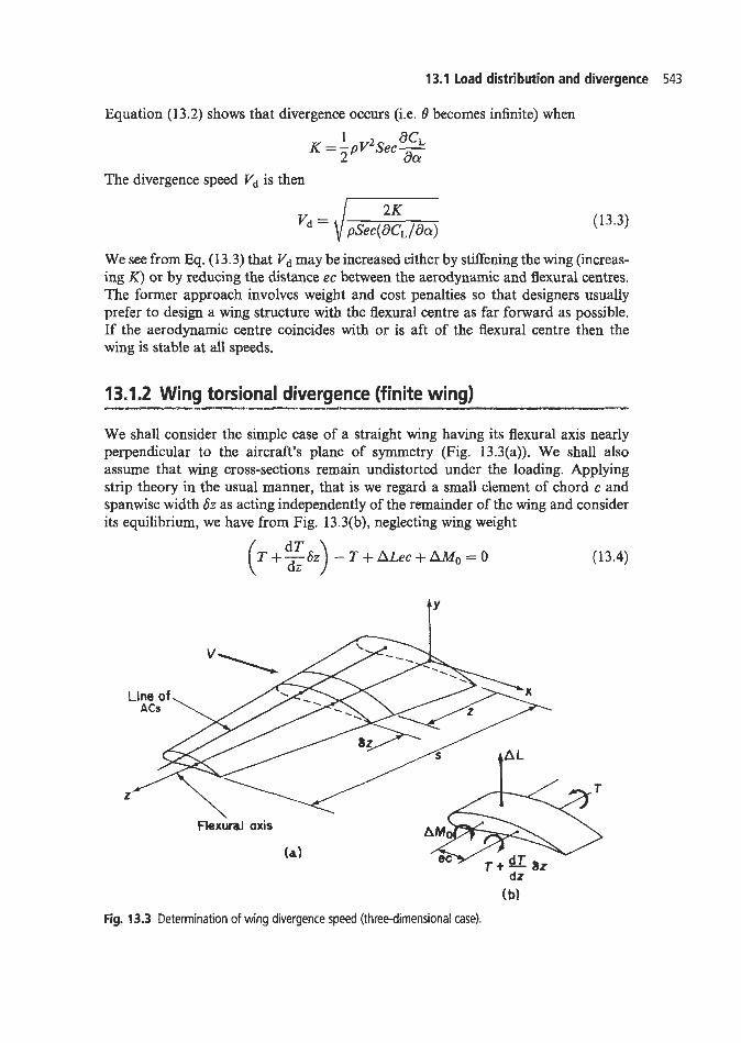
We shall consider the simple case of a straight wing having its flexural axis nearly perpendicular to the aircraft's plane of symmetry (Fig. 13.3(a)). We shall also assume that wing cross-sections remain undistorted under the loading. Applying strip theory in the usual manner, that is we regard a small element of chord c and spanwise width 6z as acting independently of the remainder of the wing and consider its equilibrium, we have from Fig. 13.3(b), neglecting wing weight
( T +g&) - T + ALec + AM, = 0 (13.4)
AY
Line of ACs
z
Flexural axis
dz (bl
Fig. 13.3 Determination of wing divergence speed (three-dimensional case).

544 Elementary aeroelasticity
where T is the applied torque at any spanwise section z and AL and AMo are the lift and pitching moment on the elemental strip acting at its aerodynamic centre. As Sz approaches zero, Eq. (13.4) becomes
dT dL dMo -+ ec-+- = 0 dz d z d z (13.5)
In Eq. (13.4)
AL = -pV2cSz-(a 1 OCl + e) 2 Sa
where dcl /acu is the local two-dimensional lift curve slope and
in which c,,~ is the local pitching moment coefficient about the aerodynamic centre. Also from torsion theory (see Chapter 3) T = GJ dO/dz. Substituting for L, Mo and T in Eq. (13.5) gives
(13.6) d28 4 pV2ec2 (acl /&)e - - $ p V2e? (del /da)a - i pV2c2c,,o -+ dz2
- GJ GJ GJ
Equation (13.6) is a second-order differential equation in 0 having a solution of the standard form
(13.7)
where
and A and B are unknown constants that are obtained from the boundary conditions; namely, 6 = 0 when z = 0 at the wing root and de/& = 0 at z = s since the torque is zero at the wing tip. From the first of these
and from the second
Hence
+ a (tanhsinAz+cosXz- 1) 6 = [ e(zTaa) I
or rearranging
(13.8)
(13.9)

13.1 load distribution and divergence 545
Therefore, at divergence when the elastic twist, 6, becomes infinite
cos As = 0
so that 7r
h = ( 2 n + 1 ) - for n=0,1,2, ...:oo (13.10)
The smallest value corresponding to the divergence speed vd occurs when n = 0, thus 2
As = 7r/2
or
from which
A2 = 3/4s2
(13.11)
Mathematical solutions of the type given in Eq. (13.10) rarely apply with any accuracy to actual wing or tail surfaces. However, they do give an indication of the order of the divergence speed, vd . In fact, when the two-dimensional lift-curve slope, d c l / a a , is used they lead to conservative estimates of v d . It has been shown that when acl/aa is replaced by the three-dimensional lift-curve slope of the finite wing, values of Vd become very close to those determined from more sophisticated aerodynamic and aeroelastic theory.
The lift distribution on a straight wing, accounting for the elastic twist, is found by introducing a relationship between incidence and lift distribution from aerodynamic theory. In the case of simple strip theory the local wing lift coefficient, c1 , is given by
in which the distribution of elastic twist 6 is known from Eq. (13.9).
----- P -1 ____.- 13.1.3 Swept wing divergence
In the calculation of divergence speeds of straight wings the flexural axis was taken to be nearly perpendicular to the aircraft’s plane of symmetry. Bending of such wings has no influence on divergence, this being entirely dependent on the twisting of the wing about its flexural axis. This is no longer the case for a swept wing where the spanwise axes are inclined to the aircraft’s plane of symmetry. Let us consider the swept wing of Fig. 13.4. The wing lift distribution causes the wing to bend in an upward direction. Points A and B on a line perpendicular to the reference axis will deflect by approximately the same amount, but this will be greater than the deflection of A’ which means that bending reduces the streamwise incidence of the wing. The corresponding negative increment of lift opposes the elastic twist, thereby reducing the possibility of wing divergence. In fact, the divergence speed of swept wings is so high that it poses no problems for the designer. Diederich and Budiansky in 1948

546 Elementary aeroelasticity
Reference \
axis ii"p Fig. 13.4 Effect of wing sweep on wing divergence speed.
showed that wings with moderate or large sweepback cannot diverge. The opposite of course is true for swept-forward wings where bending deflections have a destabilizing effect and divergence speeds are extremely low. The determination of lift distributions and divergence speeds for swept-forward wings is presented in Ref. 3.
The flexibility of the major aerodynamic surfaces (wings, vertical and horizontal tails) adversely affects the effectiveness of the corresponding control surfaces (ailerons, rudder and elevators). For example, the downward deflection of an aileron causes a nose down twisting of the wing which consequently reduces the aileron incidence. Thus, the wing twist tends to reduce the increase in lift produced by the aileron deflec- tion, and thereby the rolling moment to a value less than that for a rigid wing. The aerodynamic twisting moment on the wing due to aileron deflection increases as the square of the speed but the elastic restoring moment is constant since it depends on the torsional stiffness of the wing structure. Therefore, ailerons become markedly less effective as the speed increases until, at a particular speed, the aileron reversal speed, aileron deflection does not produce any rolling moment at all. At higher speeds reversed aileron movements are necessary in that a positive increment of wing lift requires an upward aileron deflection and vice versa.
Similar, less critical, problems arise in the loss of effectiveness and reversal of the rudder and elevator controls. They are complicated by the additional deformations of the fuselage and tailplane-fuselage attachment points, which may be as important as the deformations of the tailplane itself. We shall concentrate in this section on the problem of aileron effectiveness and reversal.
13.2.1 Aileron effectiveness and reversal (two-dimensional case)
We shall illustrate the problem by investigating, as in Section 13.1, the case of a wing- aileron combination in a two-dimensional flow. In Fig. 13.5 an aileron deflection < produces changes A L and A M , in the wing lift, L, and wing pitching moment M,;

13.2 Control effectiveness and reversal 547
L + AL
Spring stiffness K
V ____t
t- Fig. Aileron effectiveness and reversal speed (two-dimensional tax,.
these in turn cause an elastic twist, 8, of the wing. Thus
(13.12)
where aCL/aa has been previously defined and aCL/a( is the rate of change of lift coefficient with aileron angle. Also
in which aCM,o/at is the rate of change of wing pitching moment coefficient with aileron deflection. The moment produced by these increments in lift and pitching moment is equilibrated by an increment of torque AT about the flexural axis. Hence
Isolating e from Eq. (13.14) gives
pv2sc[(acL/a t )e f a c M , O / a d < e = K - $pv2Sce(aCL/aa)
Substituting for B in Eq. (13.12) we have
i f v 2 s c { ( a c L / a t ) e f acM,O/%) acL I acL] E K - 3 p V2Sce ( dCL/da) aa at
which simplifies to
(13.15)

548 Elementary aeroelasticity
The increment of wing lift is therefore a linear function of aileron deflection and becomes zero, that is aileron reversal occurs, when
Hence the aileron reversal speed, Vr, is, from Eq. (13.17)
(1 3.17)
(13.18)
We may define aileron effectiveness at speeds below the reversal speed in terms of
aileron effectiveness = AL/ALR (13.19)
the lift ALR produced by an aileron deflection on a rigid wing. Thus
where
(1 3.20)
Hence, substituting in Eq. (13.19) for AL from Eq. (13.16) and ALR from Eq. (13.20), we have
Equation (13.21) may be expressed in terms of the wing divergence speed Vd and aileron reversal speed V, , using Eqs (1 3.3) and (1 3.18) respectively; hence
1 - V’/V? 1 - V’/Vi
aileron effectiveness = (13.22)
We see that when V, = V,, which occurs when aCL/at = -(acM,o/at)/e, then the aileron is completely effective at all speeds. Such a situation arises because the nose-down wing twist caused by aileron deflection is cancelled by the nose-up twist produced by the increase in wing lift.
Although the analysis described above is based on a two-dimensional case it is sometimes used in practice to give approximate answers for finite wings. The method is to apply the theory to a representative wing cross-section at an arbitrary spanwise station and use the local wing section properties in the formulae.
13.2.2 Aileron effectiveness and reversal (finite wing)
We shall again apply strip theory to investigate the aeroelastic effects of aileron deflec- tion on a finite wing. In Fig. 13.6(a) the deflection of the aileron through an angle t produces a rolling velocity p radlsec, having the sense shown. The wing incidence at any section z is thus reduced due to p by an amount p z / V. The downward aileron deflection shown here coincides with an upward deflection on the opposite wing, thereby contributing to the rolling velocity p . The incidence of the opposite wing is therefore increased by this direction of roll. Since we are concerned with aileron

13.2 Control effectiveness and reversal 549
t’
Lines
z’
A’
X
>
T
cc;y, +-!!I az dz
( b)
Fig. 13.6 Aileron effectiveness and reversal speed (finite wing).
effects we consider the antisymmetric lift and pitching moment produced by aileron deflection. Thus, in Fig. 13.6(b), the forces and moments are changes from the level flight condition.
The lift AL on the strip shown in Fig. 13.6(b) is given by
(13.23)
where dcl /aa has been previously defined and ac, /a< is the rate of change of local wing lift coefficient with aileron angle. The function fa(.) represents aileron forces and moments along the span; for 0 < z < sl,fa(z) = 0 and for s1 < z < S , f a ( Z ) = 1. The pitching moment AMo on the elemental strip is given by
( 1 3.24) AM0 = 1 T p V 2 ? 6 z - f a ( z ) E a c m o a<
in which acm,/a< is the rate of change of local pitching moment coefficient with aileron angle.
Considering the moment equilibrium of the elemental strip of Fig. 13.6(b) we obtain, neglecting wing weight
c ~ z + ALec + AMo = 0 dz or substituting for AL and AMo from Eqs (13.23) and (13.24)
(13.25)

550 Elementary aeroelasticity
Substituting for T in Eq. (13.26) from torsion theory (7‘ = GJd8/dz) and rearranging we have
d28 ;pv2ec‘acl/aa ;pv2c2 [ acl PZ acl d z 2
e=- e - - - e-fa(z)C - *f,cz)(] (13.27) GJ GJ aa v at aC -+
Writing
we obtain
It may be shown that the solution of Eq. (13.28), satisfying the boundary conditions
8 = 0 a t z = O and dO/dz=O a t z = s
is
] (13.29) sinXz 5 sin X(s - sl) cos xr x [fa(z){ 1 - cos X(z - SI)} -
where
cos X(z - sl) = 0 when z < s1
The spanwise variation of total local wing lift coefficient is given by strip theory as
(13.30)
where 8 is known from Eq. (13.29) and a is the steady flight wing incidence. The aileron effectiveness is often measured in terms of the wing-tip helix angle
(ps/ V ) per unit aileron displacement during a steady roll. In this condition the rolling moments due to a given aileron deflection, [, wing twist and aerodynamic damping are in equilibrium so that from Fig. 13.6(a) and Eq. (13.23) and noting that ailerons on opposite wings both contribute to the rolling, we have
from which
(13.31)
(13.32)

13.3 Structural vibration 551
Substituting for 8 from Eq. (13.29) into Eq. (13.32) gives
Hence
1 sinX(s - sl) . sin Xz q{ (%+: 2) [r,e){l -cosx(z-s ] ) ) - cos As
(13.33)
Therefore, aileron effectiveness (ps / V ) / < is given by
Integration of the right-hand side of the above equation gives
1 8cm.o - e(acl /aa)
-- < (13.34)
The aileron reversal speed occurs when the aileron effectiveness is zero. Thus, equat- ing the numerator of Eq. (13.34) to zero, we obtain the transcendental equation
(%+: %) (COSXS - C O S X S ~ ) + cosXs = 0 (13.35) a€
Alternative methods of obtaining divergence and control reversal speeds employ matrix or energy procedures. Details of such treatments may be found in Ref. 3.
The remainder of this chapter is concerned with dynamic problems of aeroelasticity, of whichflutter is of primary importance. Flutter has been defined as the dynamic instability of an elastic body in an airstream and is produced by aerodynamic forces which result from the deflection of the elastic body from its undeformed state. The determination of critical or Jlutter speeds for the continuous structure of