Airbus Catia V5 Wireframe and Surface.pdf
17
AIRBUS UK CATIA V5 Foundation Course DMS42189 Page 1 of 17 Issue 1 ANS-UG0300112 Compiled by: Kevin Burke Kevin Burke Date: 16/Apr/2003 Approved by: Date: Authorised by: Date: AIRBUS UK Ltd. All rights reserved. Foundation Course Wireframe and Surfacing Overview
-
Upload
periclesleite -
Category
Documents
-
view
392 -
download
53
Transcript of Airbus Catia V5 Wireframe and Surface.pdf
AIRBUS UK CATIA V5 Foundation Course
DMS42189 Page 1 of 17 Issue 1ANS-UG0300112
Compiled by: Kevin Burke
Kevin BurkeDate: 16/Apr/2003
Approved by:
Date:
Authorised by:
Date:
AIRBUS UK Ltd. All rights reserved.
Foundation CourseWireframe and
Surfacing Overview
AIRBUS UK CATIA V5 Foundation Course
DMS42189 Page 2 of 17 Issue 1ANS-UG0300112
Contents
Session 7 – An overview of Wireframe and Surfacing...........3An Introduction to Generative Shape Design ........................................................... 4Accessing the Generative Shape Design Workbench ............................................... 5Generative Shape Design Toolbars and Icons........................................................... 6
Extrude Surface ..................................................................................................... 7Offset Surface........................................................................................................ 8Loft Surface......................................................................................................... 10Fill Surface .......................................................................................................... 12Projection ............................................................................................................ 13Split Surface ........................................................................................................ 14Join Surface ......................................................................................................... 15Extrapolate Surface ............................................................................................. 16Intersection .......................................................................................................... 17
AIRBUS UK CATIA V5 Foundation Course
DMS42189 Page 3 of 17 Issue 1ANS-UG0300112
Session 7 – An overview of Wireframeand Surfacing
On completion of this session the trainee will:
♦ Be able to access the Generative Shape Design Workbench. ♦ Be capable of creating Extruded Surfaces.
♦ Be able to create Offset Surfaces.
♦ Have a basic understanding of how to Loft a Surface.
♦ Be able to create a basic Fill Surface.
♦ Be able to Project elements onto Surfaces and Split them.
♦ Use the Join command to Join Surfaces together.
♦ Create an Extrapolated a Surface.
♦ Be able to Intersect Surfaces.
AIRBUS UK CATIA V5 Foundation Course
DMS42189 Page 4 of 17 Issue 1ANS-UG0300112
An Introduction to Generative Shape Design
There are various Workbenches within Catia where you can create both wireframeand Surface type elements. The majority can be found under the Shape andMechanical Design Functions.
For the purpose of this overview into Wireframe and Surfacing we will be using theGenerative Shape Design Workbench.
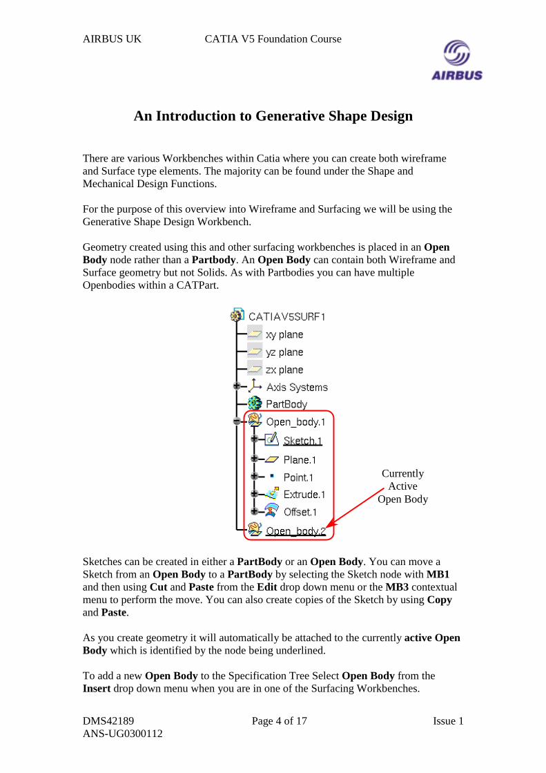
Geometry created using this and other surfacing workbenches is placed in an OpenBody node rather than a Partbody. An Open Body can contain both Wireframe andSurface geometry but not Solids. As with Partbodies you can have multipleOpenbodies within a CATPart.
Sketches can be created in either a PartBody or an Open Body. You can move aSketch from an Open Body to a PartBody by selecting the Sketch node with MB1and then using Cut and Paste from the Edit drop down menu or the MB3 contextualmenu to perform the move. You can also create copies of the Sketch by using Copyand Paste.
As you create geometry it will automatically be attached to the currently active OpenBody which is identified by the node being underlined.
To add a new Open Body to the Specification Tree Select Open Body from theInsert drop down menu when you are in one of the Surfacing Workbenches.
CurrentlyActive
Open Body
AIRBUS UK CATIA V5 Foundation Course
DMS42189 Page 5 of 17 Issue 1ANS-UG0300112
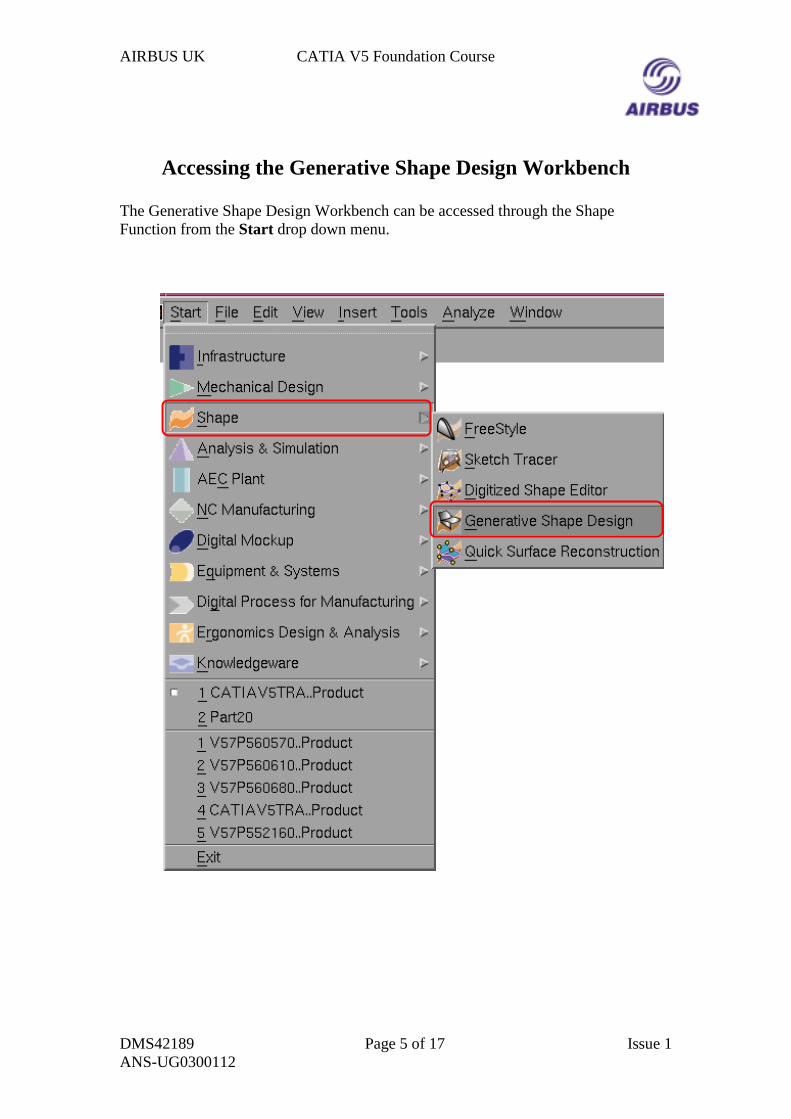
Accessing the Generative Shape Design Workbench
The Generative Shape Design Workbench can be accessed through the ShapeFunction from the Start drop down menu.
AIRBUS UK CATIA V5 Foundation Course
DMS42189 Page 6 of 17 Issue 1ANS-UG0300112
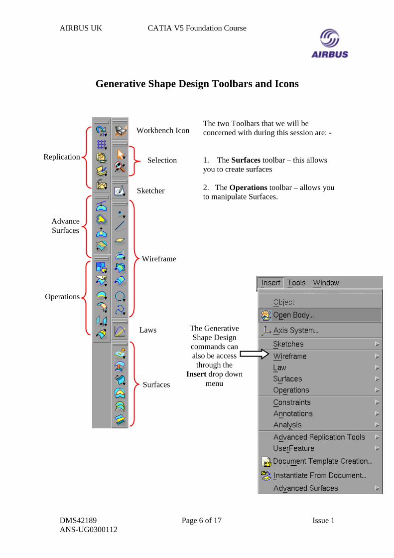
Generative Shape Design Toolbars and Icons
The two Toolbars that we will beconcerned with during this session are: -
1. The Surfaces toolbar – this allowsyou to create surfaces
2. The Operations toolbar – allows youto manipulate Surfaces.
Replication
AdvanceSurfaces
Operations
Wireframe
Surfaces
Laws
Sketcher
Workbench Icon
Selection
The GenerativeShape Designcommands canalso be access
through theInsert drop down
menu
AIRBUS UK CATIA V5 Foundation Course
DMS42189 Page 7 of 17 Issue 1ANS-UG0300112
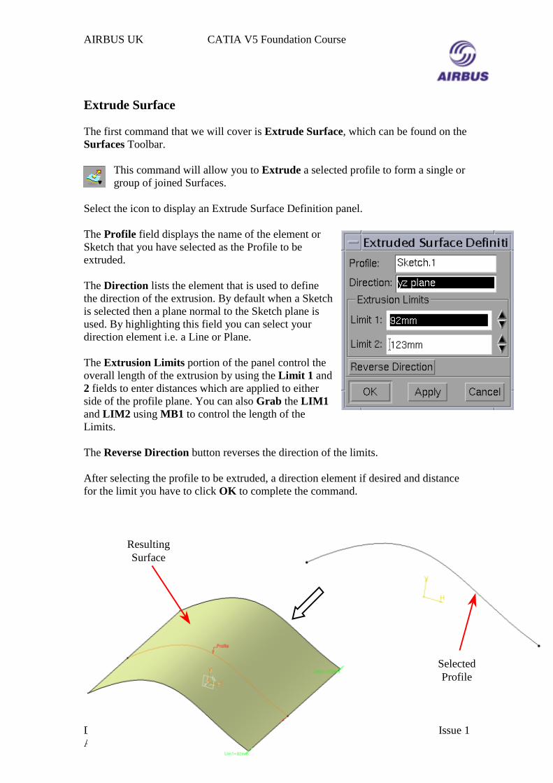
Extrude Surface
The first command that we will cover is Extrude Surface, which can be found on theSurfaces Toolbar.
This command will allow you to Extrude a selected profile to form a single orgroup of joined Surfaces.
Select the icon to display an Extrude Surface Definition panel.
The Profile field displays the name of the element orSketch that you have selected as the Profile to beextruded.
The Direction lists the element that is used to definethe direction of the extrusion. By default when a Sketchis selected then a plane normal to the Sketch plane isused. By highlighting this field you can select yourdirection element i.e. a Line or Plane.
The Extrusion Limits portion of the panel control theoverall length of the extrusion by using the Limit 1 and2 fields to enter distances which are applied to eitherside of the profile plane. You can also Grab the LIM1and LIM2 using MB1 to control the length of theLimits.
The Reverse Direction button reverses the direction of the limits.
After selecting the profile to be extruded, a direction element if desired and distancefor the limit you have to click OK to complete the command.
SelectedProfile
ResultingSurface
AIRBUS UK CATIA V5 Foundation Course
DMS42189 Page 8 of 17 Issue 1ANS-UG0300112
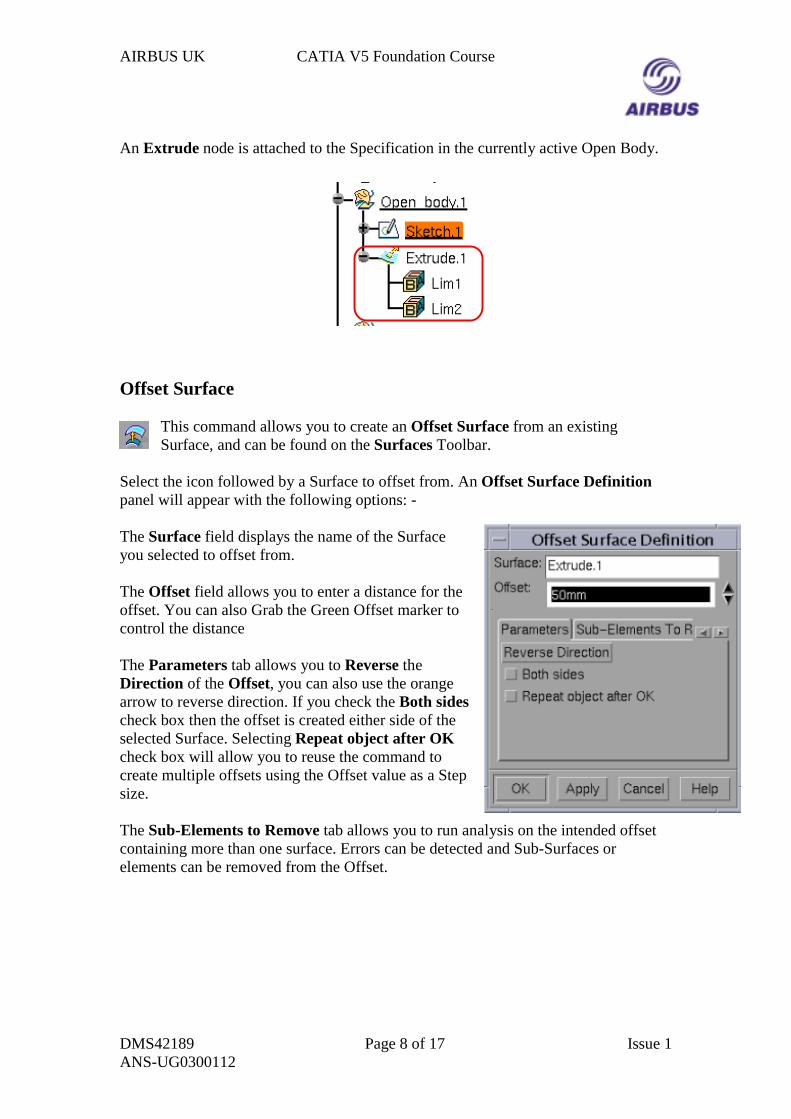
An Extrude node is attached to the Specification in the currently active Open Body.
Offset Surface
This command allows you to create an Offset Surface from an existingSurface, and can be found on the Surfaces Toolbar.
Select the icon followed by a Surface to offset from. An Offset Surface Definitionpanel will appear with the following options: -
The Surface field displays the name of the Surfaceyou selected to offset from.
The Offset field allows you to enter a distance for theoffset. You can also Grab the Green Offset marker tocontrol the distance
The Parameters tab allows you to Reverse theDirection of the Offset, you can also use the orangearrow to reverse direction. If you check the Both sidescheck box then the offset is created either side of theselected Surface. Selecting Repeat object after OKcheck box will allow you to reuse the command tocreate multiple offsets using the Offset value as a Stepsize.
The Sub-Elements to Remove tab allows you to run analysis on the intended offsetcontaining more than one surface. Errors can be detected and Sub-Surfaces orelements can be removed from the Offset.
AIRBUS UK CATIA V5 Foundation Course
DMS42189 Page 9 of 17 Issue 1ANS-UG0300112
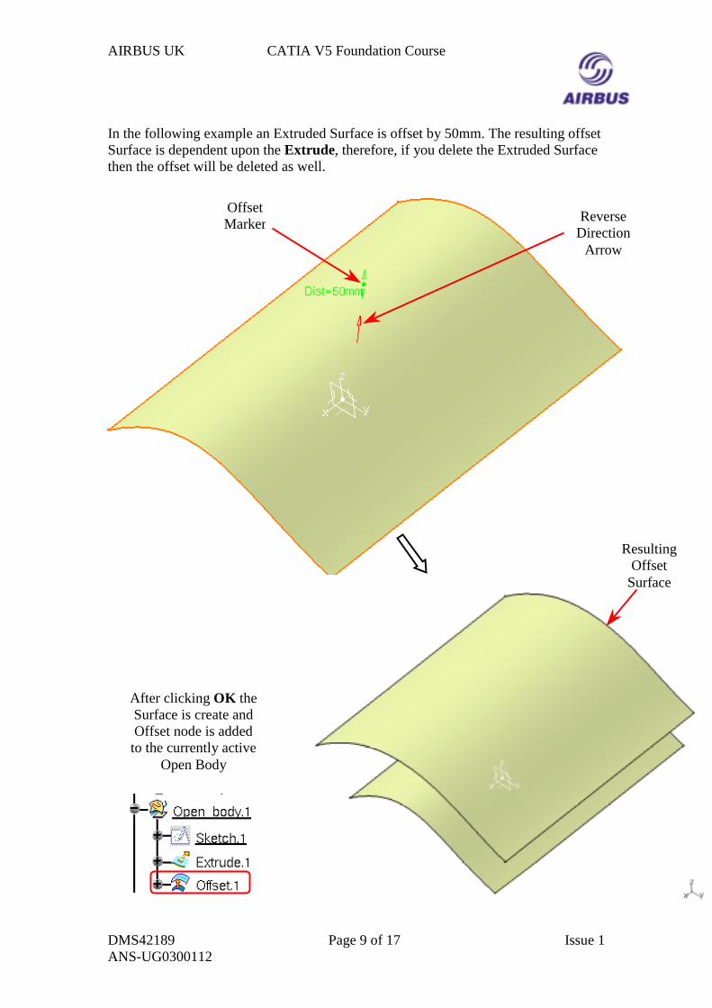
In the following example an Extruded Surface is offset by 50mm. The resulting offsetSurface is dependent upon the Extrude, therefore, if you delete the Extruded Surfacethen the offset will be deleted as well.
ReverseDirection
Arrow
OffsetMarker
ResultingOffset
Surface
After clicking OK theSurface is create andOffset node is addedto the currently active
Open Body
AIRBUS UK CATIA V5 Foundation Course
DMS42189 Page 10 of 17 Issue 1ANS-UG0300112
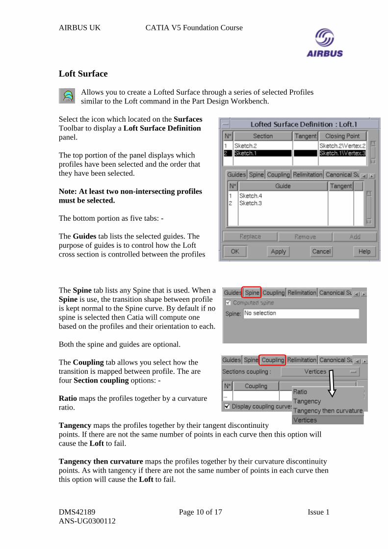
Loft Surface
Allows you to create a Lofted Surface through a series of selected Profilessimilar to the Loft command in the Part Design Workbench.
Select the icon which located on the SurfacesToolbar to display a Loft Surface Definitionpanel.
The top portion of the panel displays whichprofiles have been selected and the order thatthey have been selected.
Note: At least two non-intersecting profilesmust be selected.
The bottom portion as five tabs: -
The Guides tab lists the selected guides. Thepurpose of guides is to control how the Loftcross section is controlled between the profiles
The Spine tab lists any Spine that is used. When aSpine is use, the transition shape between profileis kept normal to the Spine curve. By default if nospine is selected then Catia will compute onebased on the profiles and their orientation to each.
Both the spine and guides are optional.
The Coupling tab allows you select how thetransition is mapped between profile. The arefour Section coupling options: -
Ratio maps the profiles together by a curvatureratio.
Tangency maps the profiles together by their tangent discontinuitypoints. If there are not the same number of points in each curve then this option willcause the Loft to fail.
Tangency then curvature maps the profiles together by their curvature discontinuitypoints. As with tangency if there are not the same number of points in each curve thenthis option will cause the Loft to fail.
AIRBUS UK CATIA V5 Foundation Course
DMS42189 Page 11 of 17 Issue 1ANS-UG0300112
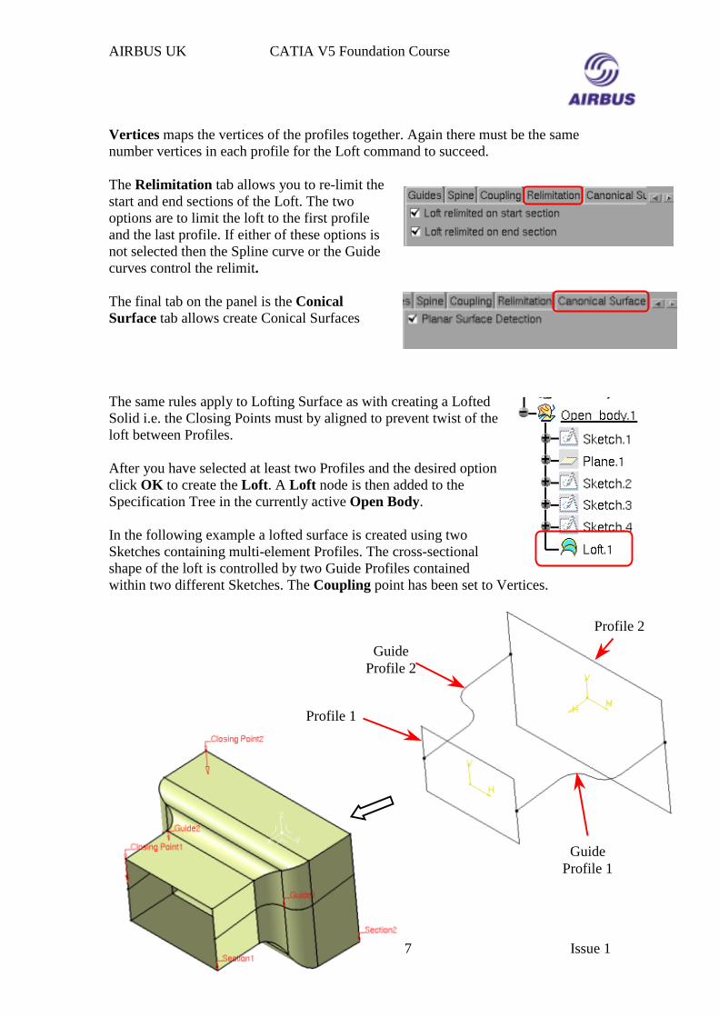
Vertices maps the vertices of the profiles together. Again there must be the samenumber vertices in each profile for the Loft command to succeed.
The Relimitation tab allows you to re-limit thestart and end sections of the Loft. The twooptions are to limit the loft to the first profileand the last profile. If either of these options isnot selected then the Spline curve or the Guidecurves control the relimit.
The final tab on the panel is the ConicalSurface tab allows create Conical Surfaces
The same rules apply to Lofting Surface as with creating a LoftedSolid i.e. the Closing Points must by aligned to prevent twist of theloft between Profiles.
After you have selected at least two Profiles and the desired optionclick OK to create the Loft. A Loft node is then added to theSpecification Tree in the currently active Open Body.
In the following example a lofted surface is created using twoSketches containing multi-element Profiles. The cross-sectionalshape of the loft is controlled by two Guide Profiles containedwithin two different Sketches. The Coupling point has been set to Vertices.
Profile 1
GuideProfile 2
Profile 2
GuideProfile 1
AIRBUS UK CATIA V5 Foundation Course
DMS42189 Page 12 of 17 Issue 1ANS-UG0300112
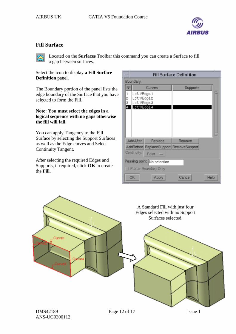
Fill Surface
Located on the Surfaces Toolbar this command you can create a Surface to filla gap between surfaces.
Select the icon to display a Fill SurfaceDefinition panel.
The Boundary portion of the panel lists theedge boundary of the Surface that you haveselected to form the Fill.
Note: You must select the edges in alogical sequence with no gaps otherwisethe fill will fail.
You can apply Tangency to the FillSurface by selecting the Support Surfacesas well as the Edge curves and SelectContinuity Tangent.
After selecting the required Edges andSupports, if required, click OK to createthe Fill.
A Standard Fill with just fourEdges selected with no Support
Surfaces selected.
AIRBUS UK CATIA V5 Foundation Course
DMS42189 Page 13 of 17 Issue 1ANS-UG0300112
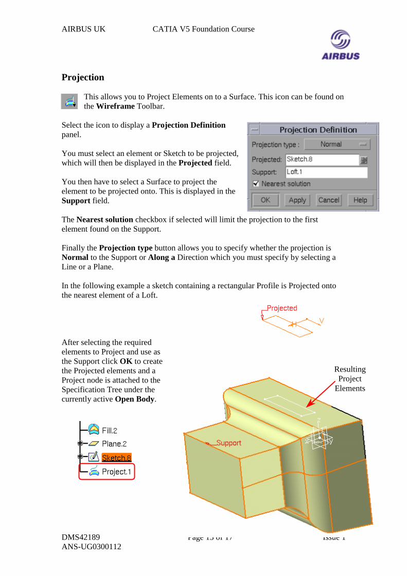
Projection
This allows you to Project Elements on to a Surface. This icon can be found onthe Wireframe Toolbar.
Select the icon to display a Projection Definitionpanel.
You must select an element or Sketch to be projected,which will then be displayed in the Projected field.
You then have to select a Surface to project theelement to be projected onto. This is displayed in theSupport field.
The Nearest solution checkbox if selected will limit the projection to the firstelement found on the Support.
Finally the Projection type button allows you to specify whether the projection isNormal to the Support or Along a Direction which you must specify by selecting aLine or a Plane.
In the following example a sketch containing a rectangular Profile is Projected ontothe nearest element of a Loft.
After selecting the requiredelements to Project and use asthe Support click OK to createthe Projected elements and aProject node is attached to theSpecification Tree under thecurrently active Open Body.
ResultingProject
Elements
AIRBUS UK CATIA V5 Foundation Course
DMS42189 Page 14 of 17 Issue 1ANS-UG0300112
Split Surface
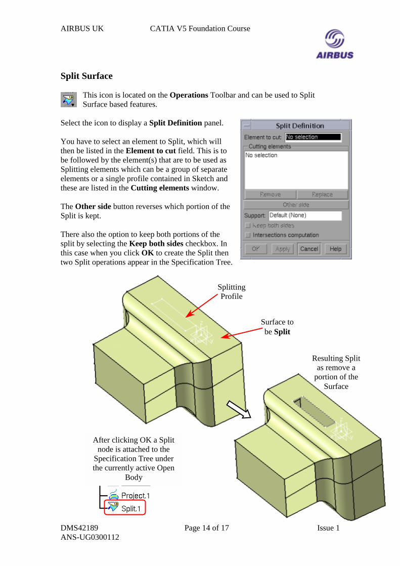
This icon is located on the Operations Toolbar and can be used to SplitSurface based features.
Select the icon to display a Split Definition panel.
You have to select an element to Split, which willthen be listed in the Element to cut field. This is tobe followed by the element(s) that are to be used asSplitting elements which can be a group of separateelements or a single profile contained in Sketch andthese are listed in the Cutting elements window.
The Other side button reverses which portion of theSplit is kept.
There also the option to keep both portions of thesplit by selecting the Keep both sides checkbox. Inthis case when you click OK to create the Split thentwo Split operations appear in the Specification Tree.
SplittingProfile
Surface tobe Split
Resulting Splitas remove a
portion of theSurface
After clicking OK a Splitnode is attached to the
Specification Tree underthe currently active Open
Body
AIRBUS UK CATIA V5 Foundation Course
DMS42189 Page 15 of 17 Issue 1ANS-UG0300112
Join Surface
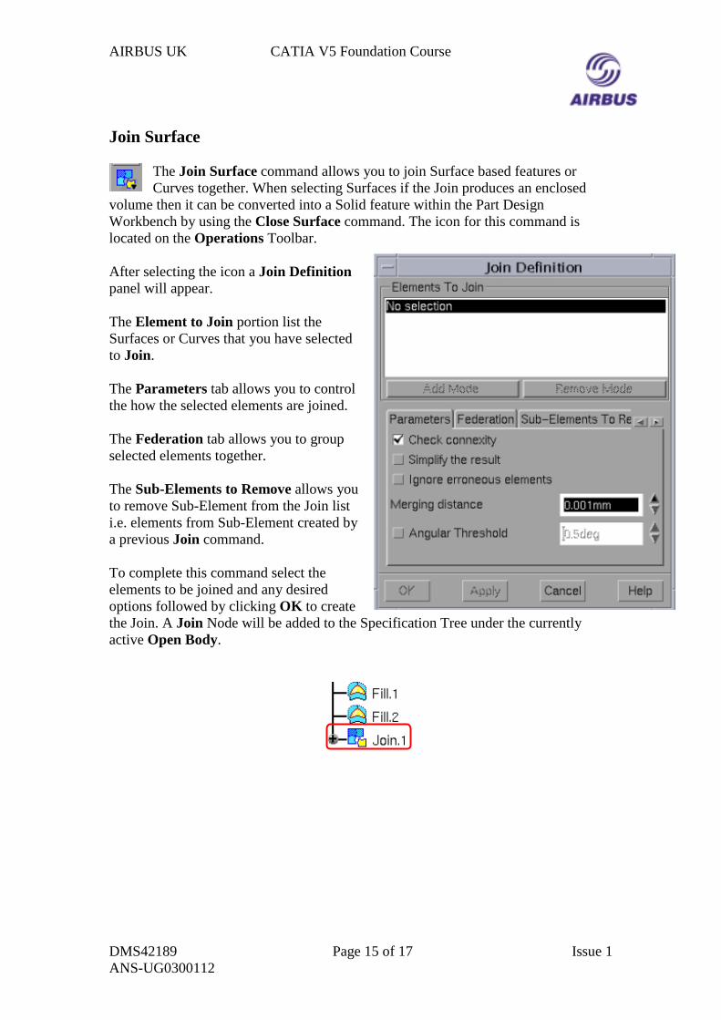
The Join Surface command allows you to join Surface based features orCurves together. When selecting Surfaces if the Join produces an enclosed
volume then it can be converted into a Solid feature within the Part DesignWorkbench by using the Close Surface command. The icon for this command islocated on the Operations Toolbar.
After selecting the icon a Join Definitionpanel will appear.
The Element to Join portion list theSurfaces or Curves that you have selectedto Join.
The Parameters tab allows you to controlthe how the selected elements are joined.
The Federation tab allows you to groupselected elements together.
The Sub-Elements to Remove allows youto remove Sub-Element from the Join listi.e. elements from Sub-Element created bya previous Join command.
To complete this command select theelements to be joined and any desiredoptions followed by clicking OK to createthe Join. A Join Node will be added to the Specification Tree under the currentlyactive Open Body.
AIRBUS UK CATIA V5 Foundation Course
DMS42189 Page 16 of 17 Issue 1ANS-UG0300112
Extrapolate Surface
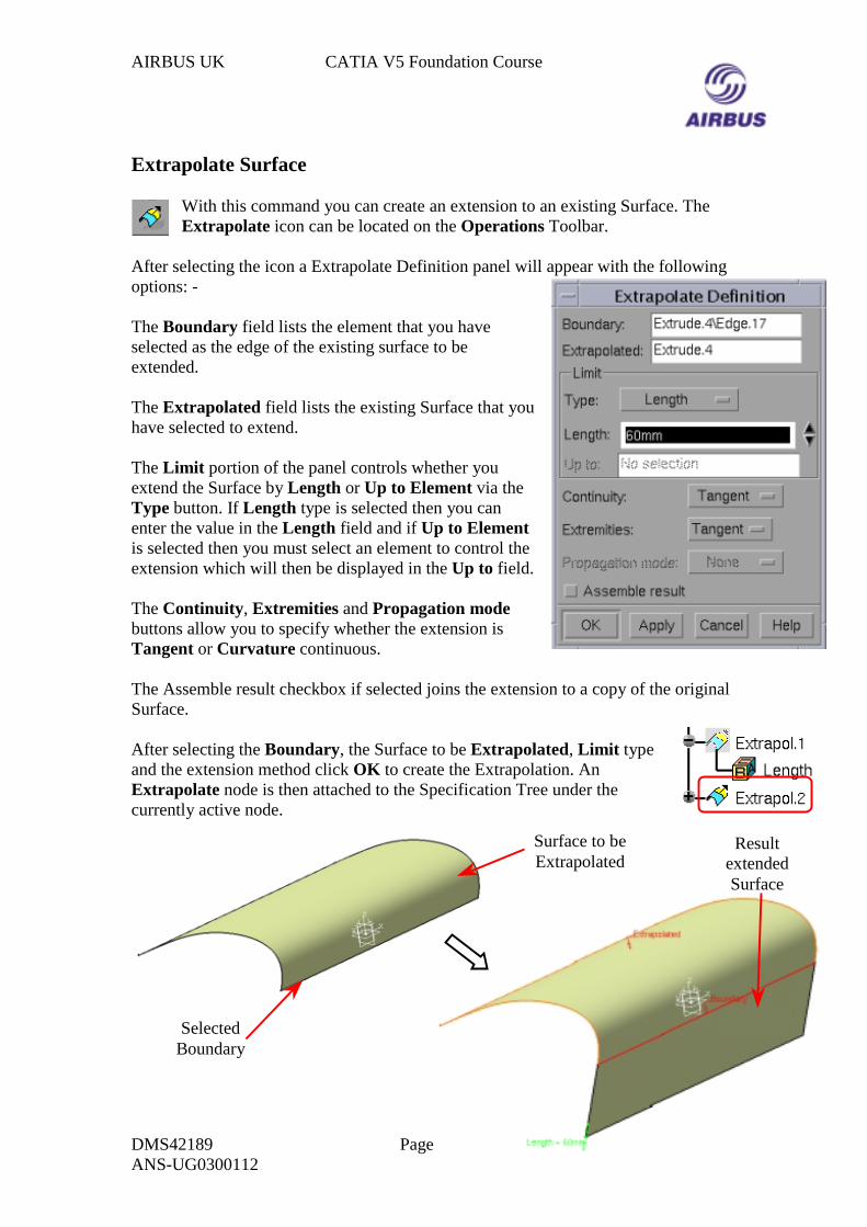
With this command you can create an extension to an existing Surface. TheExtrapolate icon can be located on the Operations Toolbar.
After selecting the icon a Extrapolate Definition panel will appear with the followingoptions: -
The Boundary field lists the element that you haveselected as the edge of the existing surface to beextended.
The Extrapolated field lists the existing Surface that youhave selected to extend.
The Limit portion of the panel controls whether youextend the Surface by Length or Up to Element via theType button. If Length type is selected then you canenter the value in the Length field and if Up to Elementis selected then you must select an element to control theextension which will then be displayed in the Up to field.
The Continuity, Extremities and Propagation modebuttons allow you to specify whether the extension isTangent or Curvature continuous.
The Assemble result checkbox if selected joins the extension to a copy of the originalSurface.
After selecting the Boundary, the Surface to be Extrapolated, Limit typeand the extension method click OK to create the Extrapolation. AnExtrapolate node is then attached to the Specification Tree under thecurrently active node.
Surface to beExtrapolated
SelectedBoundary
ResultextendedSurface
AIRBUS UK CATIA V5 Foundation Course
DMS42189 Page 17 of 17 Issue 1ANS-UG0300112
Intersection
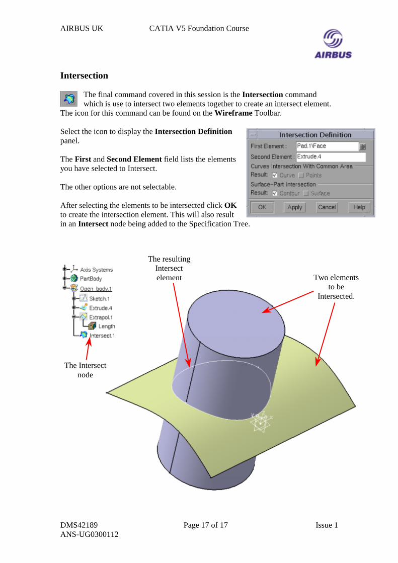
The final command covered in this session is the Intersection commandwhich is use to intersect two elements together to create an intersect element.
The icon for this command can be found on the Wireframe Toolbar.
Select the icon to display the Intersection Definitionpanel.
The First and Second Element field lists the elementsyou have selected to Intersect.
The other options are not selectable.
After selecting the elements to be intersected click OKto create the intersection element. This will also resultin an Intersect node being added to the Specification Tree.
Two elementsto be
Intersected.
The Intersectnode
The resultingIntersectelement