ADý=A280 682 - Defense Technical Information Center · ADý=A280 682 94ý1749. OBSTRUCTION MARKING...
46
ADý=A280 682 94ý1749
-
Upload
truongcong -
Category
Documents
-
view
217 -
download
0
Transcript of ADý=A280 682 - Defense Technical Information Center · ADý=A280 682 94ý1749. OBSTRUCTION MARKING...

ADý=A280 682
94ý1749
OBSTRUCTION MARKING
and LIGHTING
Reviled Sep-umhe 1961Dfl Accesion
NTIS CRA&r
.... ......................... ..
. . . .......................Dit. 'o.itiot I
Avatlab~ltyt C. ode.s
D•st il or
FEDERAL AVIATION AGENCY

ContentsP~ag
Introduction -------------------------------------------- 1Section ]- M arking ------------------------------------ 3
M arking of Vehicles ------------------------- 3Marking of Natural and Manmade Obstructions. 3
Section ll- Lighting ------------------------------------ 9Operation of Obstruction Lighting ------------- 10Obstruction Lighting Equipment -------------- 13Recommended Lamp Equipment -------------- 15
Section II1-Standards for Lighting Obstructions to Air Navi-gation ------------------------------------ 17
Towers, Poles, and Similar Obstructions -------- 17Trees -------------------------------------- 23Transmission Lines -------------------------- 23Smokestacks and Similar Obstructions --------- 24Prominent Buildings and Similar Extensive Ob-
structions --------------------------------- 27Bridges ------------------------------------- 29Water Towers, Gran Elevators, Gas Holders, and
Similar Obstructions ----------------------- 30Group of Structural Hazards ------------------ 31Hazard Areas ------------------------------- 32
Hii
Illustrations
Obstruction Light Fittings -------------------------------- 33300 mm Electric Code Beacon ---------------------------- 33Rotating Beacons --------------------------------------- 34Painting and Lighting of Towers, Poles and Similar Obstruc-
tions ------------------------------------------------- 35Graphic Portrayal of "A" Specifications for Lighting Towers,
Poles and Similar Obstructions -------------------------. 37Painting and Lighting of Smokestacks and Similar Obstruc-
tions ------------------------------------------------- 38Suspension Type Obstruction Light Installation -------.----- 39Painting and Lighting of Water Towers and Similar Obstruc-
tions ------------------------------------------------- 40Painting and Lighting of Gas Holders, and Similar Obstruc-
tions ------------------------------------------------- 42Lighting of Bridges -------------------------------------- 43Hazard Area Marker ------------------------.----------- 44
i,
I Mt mm _ m m m

INTRODUCTIONThe Administrator of the Federal Aviation Agency has the statu-
tory responsibility of promoting safety in air commerce. In the lightof this responsibility, the Federal Aviation Agency is vitally con-cerned with any object which may be a hazard to the safe operationof aircraft.
The standards for marking and lighting obstructions prescribed inthis publication are designed to provide the most effective means ofindicating the presence of obstructions to pilots. In many instancesthe obstruction may be so located in reference to other objects or thecontour of the ground, that the specific standard need be applied toonly a portion of it. Similarly, the obstruction may be so removedfrom the general flow of air traffic or may be so conspicuous by itsshape, size, or color that obstruction marking would serve no usefulpurpose and would be unnecessary. Furthermore, the obstructionmay present such a hazard that lighting should be provided similarto that for an obstruction of greater height or size. Portions of ob-structions that are shielded by surrounding objects need not bemarked or lighted, but the surrounding objects should be marked andlighted.
Because of the many influencing elements, the Federal AviationAgency may recommend modification of the obstruction marking andlighting standards described herein when aeronautical study has indi-cated that marking and lighting of an obstruction in accordance withthe recommended modification would provide suitable protection forair commerce.
Objects or portions thereof, either temporary or permanent, whichexceed the criteria of hazards to air navigation set forth in Part 77of the Federal Aviation Regulations (14 CFR 77) or the criteriaof obstructions set forth in Technical Standard Order of the Admin-istrator No. TSO-N18 and all objects or portions thereof, either tem-porary or permanent, greater than 170 feet in overall height abovesite level should be marked and lighted in accordance with the applica-ble standards herein, unless an FAA aeronautical study determinesthat the absence of such marking and/or lighting will not impairsafety in air navigation.
The specifications for obstruction marking and lighting antennastructures, contained in Subpart. C of Part 17 of the Federal Com-munications Commission's Rules and Regulations, are identical withthe standards described herein for marking obstructions with bandsof aviation surface orange and white and for lighting obstructions inaccordance with the "A" specifications.
I
I
This publication supersedes the November 1, 1953 edition of Ob.trw-&am ManWA and Lightihf published by the Civil AeronauticsAdministration.
2
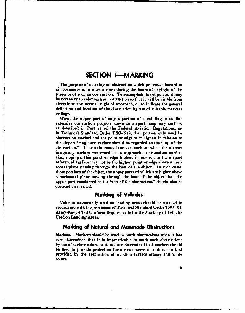
SECTION I-MARKINGThe purpose of marking an obstruction which presents a hazard to
air commerce is to warn airmen during the hours of daylight of tilepresence of such an obstruction. To accomplish this objective, it maybe necessary to color such an obstruction so that it will be visible fromaircraft at any normal angle of approach, or to indicate the generaldefinition and location of the obstruction by use of suitable markersor flags.
When the upper part of only a portion of a building or similarextensive obstruction projects above an airport imaginary surface,as described in Part 77 of the Federal Aviation Regulations, orin Technical Standard Order TSO-N18, that portion only need beobstruction marked and the point or edge of it highest in relation tothe airport imaginary surface should be regarded as the "top of theobstruction." In certain cases, however, such as when the airportimaginary surface concerned is an approach or transition surface(i.e., sloping), this point or edge highest in relation to the airportreferenced surface may not be the highest point or edge above a hori-zontal plane passing through the base of the object. In such cases,those portions of the object, the upper parts of which are higher abovea horizontal plane passing through the base of the object than theupper part considered as the "top of the obstruction," should also beobstruction marked.
Marking of VehiclesVehicles customarily used on landing areas should be marked in
accordance with the provisions of Technical Standard Order TSO-N4,Army-Navy-Civil Uniform Requirements for the Marking of VehiclesUsed on Landing Areas.
Marking of Natural and Manmade ObstructionsMarkers. Markers should be used to mark obstructions when it hasbeen determined that it is impracticable to mark such obstructionsby use of surface colors, or it has been determined that markers shouldbe used to provide protection for air commerce in addition to thatprovided by the application of aviation surface orange and whitecolor..
3

General Appicatio. Markers used to mark obstructions shouldbe displayed on or adjacent to the obstructions in conspicuous posit ionsso as to retain the general definition of the obstruction and should berecognizable in clear air from a distance of at least 1,000 feet in alldirections from which an aircraft is likely to approach the obstruction.
The shape of such markers should be distinctive to the extent neces-sary to insure that they are not mistaken for markers employed toconvey other information, and they should be such that the hazardpresented by the obstruction they mark is not increased.
Overhead Wires. Markers displayed on overhead wires should bespherical in shape with a diameter of not less than 20 incites, or maybe of another shape, provided the projection of such type of markeron any vertical surface, normal to each direction from which an air-craft is likely to approach the obstruction, will be not less than thatpresented by the spherical-type marker described above.
At least one such marker should be displayed for each 150 feet, orfraction thereof, of the overall length of the overhead line. Thesemarkers should be placed at equal intervals not more than 150 feetapart with the top of each marker not below the level of the highcstwire at the point marked, and should be colored as specified underthe marking of obstructions by "colors." The distance between mark-ers on overhead wires located more than 15,000 feet from the refer-ence point of any landing area may be increased to a distance of notmore than 600 feet.FlaIs. Flags may be used to mark obstructions when it has beendetermined that marking such obstructions by coloring or by mark-ersis technically impracticable.
The flags should be displayed around or on top of the obstructionor around its highest edge and should not increase the hazard pre-sented by the obstruction they mark. When flags are used to :nzarkextensive obstructions or groups of closely spaced obstructions, theyshould be displayed at approximately 50-foot intervals.
The flags should be rectangular in shape and have stiffeners tokeep them from drooping in calm or light wind. The flag stakes shouldbe of such strength and height that they will support the flags freeof the ground, vegetation, or nearby surfaces.
The flags should be in accordance with one of the following patterns:(a) Solid-color aviation surface orange not less than 2 feet on
a side.(b) Two triangular sections, one of aviation surface orange and
the other of aviation surface white, combined to form a rectangle notless than 2 feet on a side.
(e) A checkerboard pattern of aviation surface orange and avia-tion surface white squares, each 1 foot plus or minus 10 percent on aside, combined to form a roctangle not less than 3 feet on a side.
4

Colrs. Maximum visibility of obstructions by contrast in colors canbest be obtained by the use of aviation surface orange and white.Paints and enamels of these colors have been developed for use byGovernment agencies and private industry in marking obstructions toair navigation. In marking, either the aviation surface orange paintor enamel may be used as preferred.
The painted surfaces of obstructions should be cleaned or repaintedas often as necessary to maintain good visibility.
If the smooth surface of the paint on the ladders, decks, and walk-ways of certain types of steel towers and similar structures presentsa potential danger to maintenance personnel, such surfaces need notbe painted. However, the omission of paint should be restricted toactual surfaces the painting of which will present a hazard to main-tenance personnel, and care should be taken that the overall markingeffect of the painting is not reduced.
Solid. Obstructions the projection of which on any vertical planehas both dimensions less than 5 feet should be colored aviation surfaceorange.
Bands. Towers, poles, smokestacks, and similar obstructions, aswell as buildings of certain shape and dimensions, having essentiallyunbroken surfaces the projection of which on any vertical plane is 5feet or more in one dimension and is less than 15 feet in the otherdimension, and any skeleton- or smokestack-type obstruction havingboth dimensions 5 feet. or more, should be colored to show alternatebands of aviation surface orange and white.
The bands should be perpendicular to the major axis of the obstruc-tion, with the band at each end colored aviation surface orange. Thewidths of the bands should be equal and the width of each band shouldbe approximately one-seventh of the length of the major axis of theobstruction, provided that each band shall have a width of not morethan 40 feet nor less than 1% feet. If it is technically impracticable tocolor the roof of a building to show alternate bands of aviation sur-face orange and white, such roof may be colored aviation surfaceorange.
Checkerboard Pattern. Water towers, grain elevators, gas holders.and similar obstructions, as well as buildings of certain shape anddimensions, having essentially unbroken surfaces the projection ofwhich on any vertical plane is 15 feet or more in both dimensions.should have their top and vertical surfaces colored to show a checker-board pattern of alternate rectangles of aviation surface orange andwhite. If it. is technically impracticable to color the roof of a buildingto show alternate rectangles of aviation surface orange and white,such roof may be colored aviation surface orange.
5UWWt O-3---

-I
The sides of the rectangles should measure not less than 5 feet normore than 20 feet. The rectangles at the corners of surfaces shouldbe colored aviat ion surface orange.
If a part of a water tower, gas holder, building, or similar obstruc-tion consists of a skeleton-type construction, that portion of the ob-struction should be colored with alternate bands of aviation surfaceorange and white as specified for towers, poles, smokestacks, andsimilar obstructions. In this case, if the portion of the obstruction,which is to be colored to show at checkerboard pattern of alternaterectangles of aviation surface orange and white, has any surfaces theprojection of which on any vertical plane is less than 15 feet in eitherdimension, the alternate rectangles of aviation surface orange andwhite may have dimensions of less than 5 feet on a side. providedtheir dimensions remain as close as is practicable to the inininium 5feet specified for coloring by the checkerboard pattern.
If the size and shape of water towers, grain elevators. pas holders.and similar obstructions come within the dimensions set forth underthe specification for coloring by band,. or if their type of construe-tion does not permit coloring by the checkerboard pattern as herein-before described, then such obstructions should be colored by handsas specified for towers, poles, smokestacks, and similar obstructions.Where this method of coloring is employed, the top aviation surfaceorange band should be continued from the vertical surface so as tocover the entire top of the obstruction.
If a part, or all, of certain obstructions such as water towers andgas holders of spherical shape does not permit the exact applicationof the checkerboard pattern of coloring. then the shape of the alter-nate rectangles of aviation surface orange and white covering thespherical shape may be modified to fit the particular shape of thestructural surface, provided the dimensions of these imolified rec-tangles remain to the extent practicable within the dimensional limitsset forth in the specifications for coloring by the checkerboard pattern.
If certain obstructions such as gas holders and grain elevators areof such large size that the application of the checkerboard pattern ofcoloring to the complete outer surface of the structure would be im-practicable, the application of the checkerboard pattern of coloringmay be limited to the upper one-third of the structure. provided aero-nautical study indicates that the modified marking will provide ade-quate protection for air navigation.Spcial Day Ughting. The display of flashing or steady burning lightson an obstruction during daylight, hours, for the purpose of warningairmen of the presence of such an obstruction, may be prescribed undercertain conditions.
il

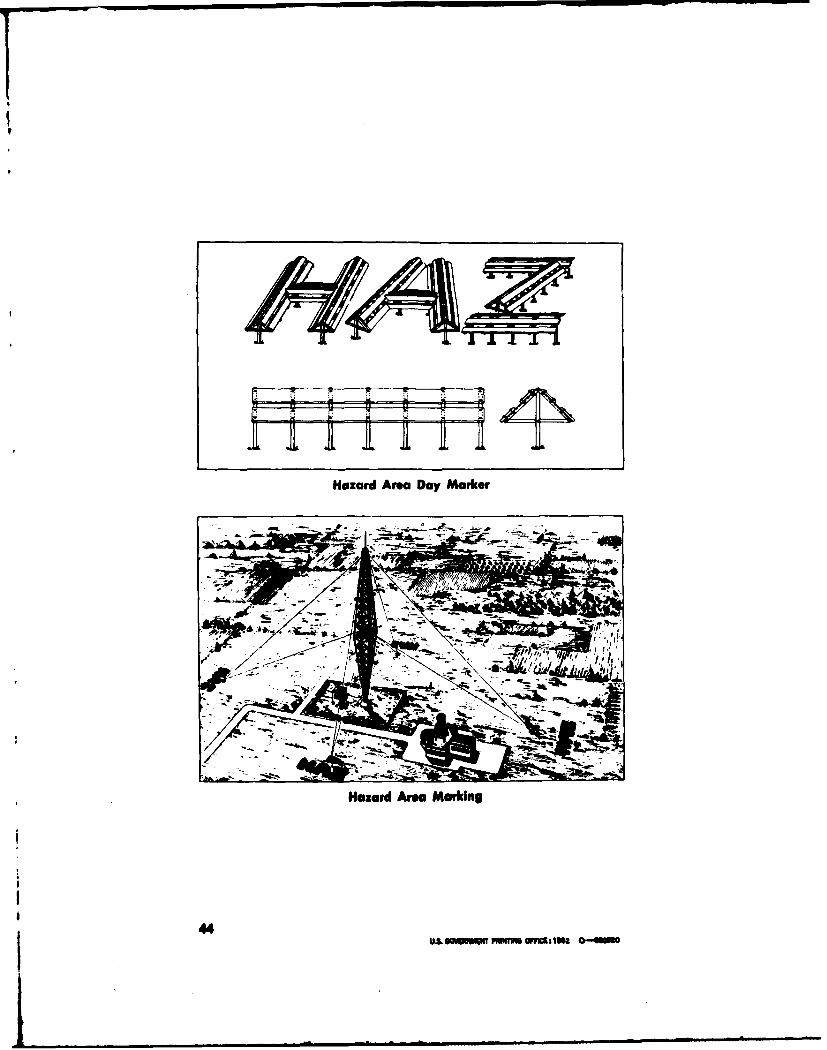
The foregoing day lighting is intended to provide protection inaddition to that provided by the applieable marking standard herein-before described.Marking of Hazaud Areas. In an area where towers, poles, and sim-ilar obstructions are so grouped as to present a (o'0imion0 hlitizard toair commerce; where the hazard of a lartiul'lar obstruction is in-creased by guy wires or other appurtenances. or where an invisiblehazard to aircraft. in flight exists, the outer limits of the area shouldbe marked by four (4) or more symbols consisting of the letters"IfAZ," located so that at least one symbol will he visible from air-craft. at any normal angle of approach. In the case of a structuralhazard secured by guy wires, the marking symbols should be locatedimmediately beyond the ground connection of the outer guy wires.
The letters of such symbols should be installed in a manner to belegible in clear air at an altitude of 3,000 feet at a distance of 2 miles.Moreover, the symbols should consist of uniform block letters havinga height of at least 30 feet and a width equal to two-thirds of theheight. The width of each stroke should be app)roximately one-seventh of the height of the letters. In addition, the letters should becolored aviation surface orange.
The symbols should be cleaned and repainted as often as necessiaryto maintain good visibility. If the strokes of the letters are coin-structed of wood or metal panels, such construct ion should he designedto prevent an accumulation of snow. The foregoing marking is in-tended to provide additional protection for air commerce n(and doesnot lessen the need for marking the prominent obstruction. or obstrii.-tions, located within the area.
• •I m• m mm~mm7
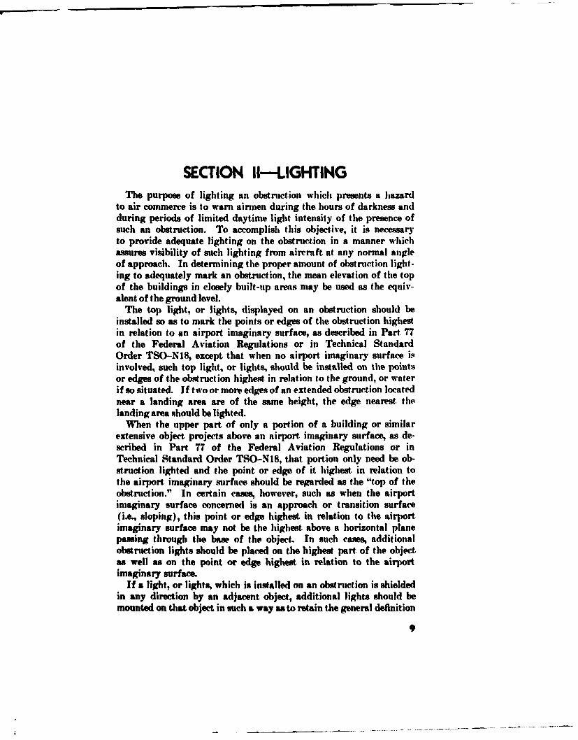
SECTION IU-LIGHTINGThe purpose of lighting an obstrnction which presents a hazard
to air commerce is to warn airmen during the hours of darkness andduring periods of limited daytime light intensity of the presence ofsuch an obstruction. To accomplish this objective, it is necessaryto provide adequate lighting on the obstruct.ion in a manner whichassures visibility of such lighting from aircraft. at any normal angleof approach. In determining the proper amount of obstruction light-ing to adequately mark an obstruction, the mean elevation of the topof the buildings in closely built-up areas may be used as the equiv-alent of the ground level.
The top light, or lights, displayed on an obstruction should beinstalled so as to mark the points or edges of the obstruction highestin relation to an airport imaginary surface, as described in Part 77of the Federal Aviation Regulations or in Technical StandardOrder TSO-N18, except that when no airport. imaginary surface isinvolved, such top light, or lights, should be installed on the pointsor edges of the obstruction highest in relation to the ground, or waterif so situated. If two or more edges of an extended obstruction locatednear a landing area are of the same height, the edge nearest, thelanding area should be lighted.
When the upper part of only a portion of a building or similarextensive object projects above an airport. imaginary surface, as de-scribed in Part 77 of the Federal Aviation Regulations or inTechnical Standard Order TSO-N18, that portion only need be ob-struction lighted and the point or edge of it highest in relation tothe airport imaginary surface should be regarded as the "top of theobstrnction." In certain cases, however, such as when the airportimaginary surface concerned is an approach or transition surface(i.e., sloping), this point or edge highest in relation to the airportimaginary surface may not be the highest. above a horizontal planepawing through the base of the object. In such cases, additionalobstruction lights should be placed on the highest part. of the object.as well as on the point or edge highest in relation to the airportimaginary surface.
If a light, or lights, which is installed on an obstruction is shieldedin any direction by an adjacent object, additional lights should bemounted on that object in such a way as to retain the general definition
9

of the obstruction, the shielded light, or lights, being omitted if itdoes not contribute to the definition of the obstruction.
Obstruction lights and hazard beacons should be operated at alltimes when the center of the sun's disk is V0 or more below the horizonand during periods of restricted visibility. They may also he operatedat such other times as considered desirable. For the Ipurpose of thisstandard, the term "sunset to sunrise" shall be generally regarded asthat period when the center of the sun's disk is 6d or more below thehorizon.Temporary Warning LIghts. When an obstruction to air navigationis presented during construction of a structure at least two lights.each light consisting of a lamp of at least 100 watts enclosed in anaviation red obstruction light globe, should be installed at the upper-most point of the structure. In addition, as the height of the struc-ture exceeds each level at which permanent obstruction lights will berequired, two similar lights should be installed at each such level.These temporary warning lights should be displayed nightly fromsunset to sunrise until the permanent obstruction lights have beeninstalled and placed in operation, and should be positioned so as toinsure unobstructed visibility of at least one of the lights at each levelfrom aircraft at any normal angle of approach. It will be permissible,in the event it is more practicable, to install and operate the perma-nent obstruction lighting fixtures at each required level, in lieu ofthe above temporary warning lights, as each suclh level is exceeded inheight during construction.
Operation of Obstruction LightingUght.Sonsifive Control Device. The operation of obstruction lightinginstalled on obstructions of an overall height greater than 150 feetabove ground, or water if so situated, should be controlled by a light-sensitive control device adjusted so that the lights will be turned on ata north sky light intensity level of about 35 foot-candles and turnedoff at a north sky light intensity level of about 58 foot-candles, orshould be continuous.
Under normal conditions, where no special means of controllingobstruction lighting has been recommended, either a light-sensitivecontrol device or an astronomic dial clock and time switch may beused to control the obstruction lighting in lieu of manual control.Inspection of Obstruction UghtIng. Obstruction lighting should bevisually observed at least once each 24 hours, or checked by observingan automatic and properly maintained indicator designed to registerany failure of such lights, to insure that all such lights are function-ing properly as required. In the event the obstruction lighting isnot readily accessible for the above observation at least once each 24
10

hours, an automatic alarm system designed t eetayfiueosuch lights niay be installed to replace flie norniatily reqaaire vi-sual
slam crcut. rovdedfli minalogdevice will idct ilue
tio ontheobstruction, and of altpigs.and that all olisinwcijoulihsmounted on thip obstruct ion are visually inspected at least onceevr 1weeks, withI all lamips being replaced at regular inutervals aftier
being lighted the equivalent of not more than 75 perceent of theirnoral ifeexpectancy.
Nwinkatiw of Light Fll~w.. Any observed or otherwise known~ ex-tinguishment or improper functijoning of at rotating or Hlashing bieeaonlight, regardless of its posit ion on at nat ural or niannmade oW.truct ion.which will last more than: 34) iminuites., aimd any~l observed or otherwiseknown extinguishment or inipropier functioiting of a steadky burniingobstruction light, installed at thep top or neair tot, of any natural ormiannmade obstruction. which wvill last more ttian :UP minutifes. shouldbe immediately reported. Such reports should be niade byv telephonieor telegraph to the nearest flightt service station or office of FederalAviation Agency and should set forth tOe cond~itionl of the light. orlights, the circumstance whticht catused time failure and the probabledate thant normal operattion will hep resumed. Further ntotification i bytelephone or telegratph sho1u(ld be gi %-Pt imitediaitely upon relsunljpt ionof normal operation by the light.orliglmts.
Any ext inguishintent or iltpropier functioning of a steady burtningside or intermediate light, or lights, installed on a nat ural (or maniatndeobstruct ion should be corrected as soon ats possib~le, but not ificat ionof such extinguishment or imp~roper functioning is not necessary.Fleshing Fooquency of Lighft. A rotating bieacon shiould produce aflash not less than 12 times per minute nor muore thant DS times pier ntin-ute. A flashing beacon should hie equippedl with ta flashiumg ntec-ai-nion producing not more than: 44) flashes pier iniatute nor less than: sflashes per minute with a period of darkness equal ito applroxintatelyone-half the luminous period. except thant thep frequency of flashes ofan obstruction beacon mioanted on amt obstruction loc-ated within 150M)~feet of the reference point of a landing area should be not less than 20per minute.
A flashing beacon may flash: an Interniational Morse ('ode Signalfor purposes of identification, provided the code characteristic doesnot consist of more than two letters, the proper aviation color char-acteristic is retained, and the luminotus output of the beacon is; notaffected in such a manner as to redutce the beatcon's effectiveniess inperforming the Service for which it was originally installed. Theduration of the illumination and velipse periods is important to insure
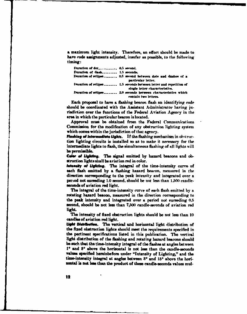
a maximum light intensity. Therefore, an effort, should be made tohave code assignments adjusted, insofar as possible, to the followingtiming:
Duration of dot ---------- 0.5 second.Duration of dash --------- 1.5 seconds.Duration of eclipse -------. . 5 second between dots and dashes of a
particular letter.I hratiou of eclipse --------.... second%, between letter and repetition of
single letter characteristics.Duration of e eipse -------- 10 seconds between characteristics which
contain two letters.
Each proposal to have a flashing beacon flash an identifying codeshould be coordinated with the Assistant Administrator having ju-risdiction over the functions of the Federal Aviation Agency in thearea in which the particular beacon is located.
Approval must. be obtained from the Federal CommunicationsCommission for the modification of any obstruction lighting systemwhich comes within the jurisdiction of that agency.Flhinu f ol lntermedlatU Lights. If the flashing mechanism in obstrue-tion lighting circuits is installed so as to make it necessary for theintermediate lights to flash, the simultaneous flashing of all lights willbe permissible.Cole. of UIghting. The signal emitted by hazard beacons and ob-struction lights shall be aviation red in color.Inmonsay of ULighg. The integral of the time-intensity curve ofeach flash emitted by a flashing hazard beacon, measured in thedirection corresponding to the peak intensity and integrated over aperiod not exceeding 1.0 second, should be not less than 1.500 candle-seconds of aviation red light.
The integral of the time-intensity curve of each flash emitted by arotating hazard beacon, measured in the direction corresponding tothe peak intensity and integrated over a period not. exceeding 0.5second, should be not less than 7,500 candle-seconds of aviation redlight.
The intensity of fixed obstruction lights should be not less than 10candles of aviation red light.LIt Dudtrwft. The vertical and horizontal light distribution ofthe fixed obstruction lights should meet the requirements specified inthe pertinent specifications listed in this publication. The verticallight distribution of the flashing and rotating hazard beacons shouldbe ssch that the time-intensity integral of the flashes at angles between1P and 8° above the horizontal is not less than the candle-secondsvalues specified hereinbefore under "Intensity of Lighting," and thetime-intensity integral at angles between 30 and 150 above the hori-zontal is not less than the product of these candle-seconds values mul-
12

tiplied by 9 over the square of the numerical value in degrees of theangle above the horizontal.Rated Lamp Voltage. To provide satisfactory output by obstructionlights, the rated voltage of the lamp used should, in each case, cor-respond to or be within 3 percent higher than the average voltageacross the lamp during the normal hours of operat ion.Interference With Railway Signals. Where obstruction lighting isinstalled on obstructions which are located along or near railroadrights-of-way and thereby constitutes a potential hazard to the safeoperation of railway trains, extreme care should be taken to preventany possibility of these obstruction lights being mistaken by loco-motive engineers for railway signal lights. The appropriate AssistantAdministrator of the Federal Aviation Agency is responsible forassuring that such obstruct ion lighting installations are fully coordi-nated with all parties concerned and that proper corrective measuresare determined and placed in effect. Shielding of the obstructionlights from the view of the locomotive engineers, if practicable, shouldbe considered: the fixed lights on the obstruction may be made toflash; or the lights at. the lower levels of the obstruction may be ex-tinguished if their extinguishment does not. materially increase thehazard to air navigation cauged by the presence of the obstruction.
Approyal must. be obtained front the Federal Communications Com-mission for the modification of any obstruction lighting system whichcomes.within the jurisdiction of that agency.Obstruction Lighting by Nonstandard Lights. Obstruction lightinginstallations may utilize incandescent lamps other than those speci-fled under the recommended lamp equipment, gaseous tubes such asneon tubes, or any method other than the conventional incandescentlamps, provided such lighting installations offer equal or greater lightintensity in all angles of azimuth and elevation than that specifiedfor standard obstruction light assemblies, afford equal or greater de-pendability of operation, and possess the color characteristics pre-scribed in the following specifications.
Obstruction Lighting EquipmentSpecIfications and Drawings. The lighting equipment, paint and avi-ation colors referred to in the standards set forth in this publicationshould conform with the applicable provisions of the following speci-fications and their related drawings.
Rotating Beacons
(a) Federal Aviation Agency Specification 291Beacons, 36-inch, Rotating Double Ended Type
(b) Federal Aviation Agency Specification 232Beacons, 24-inch, Rotating Dome Type
13

(c) Military Specification MItrL--7158Lamp Assembly-24-inch Rigid D)run Type Rotating
Beacon
Flashing Code Beacons
(a) Federal Aviation Agency Specification 446Code Beacons, 300 mm
Double and Single Obstruction Lights
(a) Military Specification MIIT-I7830Light, Navigational Boundary and Obstruction Markers
(b) Federal Aviation Agency Specification 1,810Specification for Obstruction Light
Covers for Aeronautical Lights
(a) Military Specification MIIC-7989Covers: Light-Transmitting (for Aeronautical Lights)
Astronomic Dial Clock and Time Switch
(a) Federal Aviation Agency Specification 618Astronomic Dial Clock and Time Switch
Aviation Colors
(a) Air Force-Navy Aeronautical Specification AN-C-56Colors; Aeronautical Lights and Lighting Equipment
(b) Federal Specification TT-C-595Color Guide; Ready Mixed Paint
(1) Orange No. 12197 (Aviation Surface Orange)(2) White No. 17975 (Aviation White)
Aviation Surface Paint
(a) Federal Specification TT-l '-,,9Aviation Surface Orane Paint
(b) Federal Specification TT-E-489Aviation Surface Orange Enamel
(c) Federal Specification TT-P-102Outside White Paint
Air Force-Navy Aeronautical Standard Drawings(a) AN2541
Globe-Marker Lamp(b) AN2547
Fitting Assembly-Marker Lamp(c) AN2563
Lamp Assembly-Si9igle 24-inch, Rigid, Drum Type Rotat-ing Beacon
14
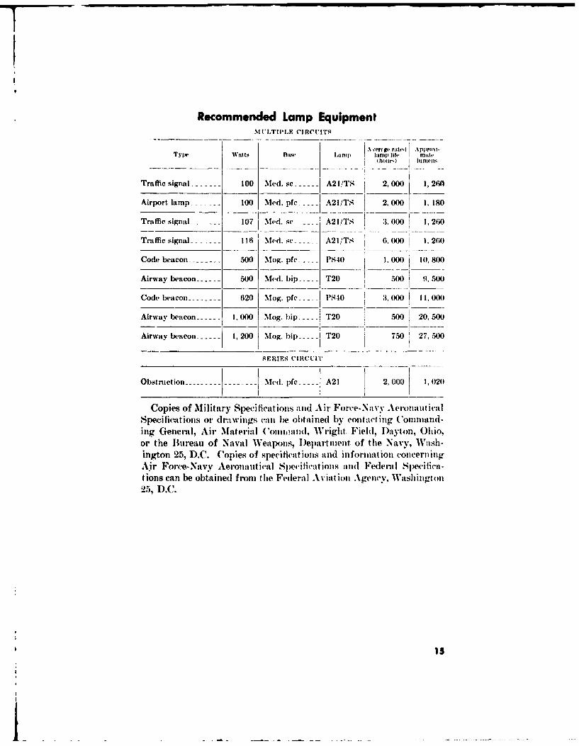
Recommended Lamp EquipmentM UILTILE CIRCUITS
A •'er ge rted I Approxi-Tylpe IWaattsL p Jamp life matte
(ho~ijr) linens
Traffic signal -------- 100 Med. sc ------ A21/TS 2,000( 1,2601
Airport. lamp -------- 100) Md. pfc ..... A21/TS 2, 000 1, 180
Traffic signal ------- 107 Med. sc ..... A21/TS 3. 000 1,260
Traffic signal ------- 116 Med. sc ------ A21/Ts 6. 000 1.260
Code beacon -------- 500 Mog. pfc -.-- PS40 1,000 10,800
Airway beacon 500 Med. bip ----- T20 500 9,500
Code beacon --------- 620 Mog. pfc- ---- PS-40 3, 000 11,00()
Airway beacon ...... 1,000 Mog. bip .Aw baoT20 500 20, 500
Airway beacon ------ 1,200 Mog. hip ----- T20 750 27,500
SERIES CIRCUIT
Obstruction --------- Med. pfe -..... A21 2,000 1,020
Copies of Military Specifications and Air Force-Navy Aeronat icalSpecifications or drawings can be obtained by contacting ('ommand-ing General, Air Material ('onnoand, Wright Fielh, 1)ayton, Ohio.or the Bureau of Naval Weapons, I)epartment of the Navy, Wash-ington 25, D.C. Copies of specifications and information concerningAir Force-Navy Aeronautical Specifications and Federal Specifica-tions can be obtained from the Federal Aviat ion Agency, Washington2.5, D.C.
B1
L
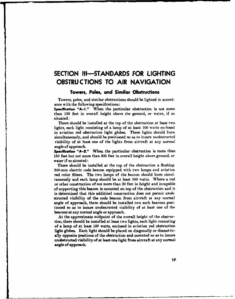
SECTION Ill-STANDARDS FOR LIGHTINGOBSTRUCTIONS TO AIR NAVIGATION
Towers, Poles, and Similar Obstructions
Towers, poles, and similar obstructions should be lighted in accord-ance with the following specifications:Specification "A-I." When the particular obstruction is not morethan 150 feet in overall height above the ground, or water, ifsituated:
There should be installed at the top of the obstruction at least twolights, each light consisting of a lamp of at least 100 watts enclosedin aviation red obstruction light globes. These lights should burnsimultaneously, and should be positioned so as to insure unobstructedvisibility of at least one of the lights from aircraft at any normalangle of approach.Specification "A-2." When the particular obstruction is more than150 feet but not more than 300 feet in overall height above ground, orwater if so situated:
There should be installed at the top of the obstruction a flashing300-mm electric code beacon equipped with two lamps and aviationred color filters. The two lamps of the beacon should burn simul-taneously and each lamp should be at least 500 watts. Where a rodor other construction of not more than 20 feet in height and incapableof supporting this beacon is mounted on top of the obstruction and itis determined that this additinal construction does not permit unob-structed visibility of the code beacon from aircraft at any normalangle of approach, there should be installed two such beacons posi-tioned so as to insure unobstructed visibility of at least one of thebeacons at any normal angle or approach.
At the approximate midpoint of the overall height of the obstruc-tion, there should be installed at least two lights, each light consistingof a lamp of at least 100 watts, enclosed in aviation red obstructionlight globes. Each light should be placed on diagonally or diametric-ally opposite positions of the obstruction and mounted so as to insureunobstructed visibility of at least one light from aircraft at any normalangle of approach.
17

In case of a triangular or rectangular shaped tower, the lights atthe midlevel should be mounted so as to insure unobstructed isihilityof at least one light from aircraft at any normal :,nle of . i 1roach. ora light. should be installed on each corner of the tower at tlii• level.Specification "A-3." When the particular obstiruction is more than300 feet. but not more than 450 feet in overall height above ground,or water if so situated :
There should be installed at the top of the obstructiri .a flashing300-mm electric code beacon equip)ped with two lail)S and aviationred color filters. The two lamps of the beacon should burn simul-taneously and each should be at least 500 watts. Where aI rod orother construction of not, more than 20 feet in height and inapableof supporting this beacon is mounted on top of the obstruction andit, is determined that this additional construction does not permitunobstructed visibility of the code beacon from aircraft at any normalangle of approach, there should be installed two such beacons posi-tioned so as to insure unobstructed visibility of at least one of lhebeacons from aircraft at any normal angle of approach.
On levels at approximately two-thirds and one-third of the overallheight of the obstruction, there should be installed at least two lights,each light consisting of a lamnp) of at least 100 watts, enclosed in avia-tion red obstruction light globes. Each light should be l)l:aed ondiagonally or diametrically opposite positions of the obstruction andmounted so as to insure unobstructed visibilitv of at least one light ateach level from aircraft at any normal angle of approach.
In case of a triangular or rectangular shaped tower, the lights atthe two-thirds and one-third levels should be mounted so as to insureunobstructed visibility' of at. least one light on each level f romn aircraftat any normal angle of approach, or a light should be installed oneach corner of the obstruct ion at each level.Specification "A-4." When the particular obstruction is more than450 feet. but not more than 600 feet in overall height above ground. orwater if so situated:i There should be installed at the top of the obstruction a flashing300-mm electric code beacon equipped withi two lamps and aviationred color filters. The two lamps of the beacon should burn simul-taneously and each should be at least 5O wvatts. Where a rod orother construction of not more than 20 feet. in height. and incapableof supporting this beacon is mounted on top of the obstruction andit is determined that this additional construction does jiot permitunobstructed visibility of the code beacon from aircraft at any normalangle of approach, there should be installed two such beacons posi-tioned so as to insure unobstructed visibility of at. least one of thebeacons from aircraft at any normal angle of approach.
16

At approximately one-half of the overall height of the obstruc-tion, a similar flashing 300-mam electric code beacon should be instaledin such a position within the obstruction proper that the structuralmembers will not impair visibility of this beacon from aircraft at anynormal angle of approach. In the event this beacon cannot be installedin a manner to insure unobstructed visibility of it from aircraft atany normal angle of approach, there should be installed two suchbeacons. Each beacon should be m,,unted on the outside of diagonallyopposite corners or opposite sides of the obstruction at the prescribedheight.
On levels of approximately three-fourths and one-fourth of theoverall height of the obstruction one or more lights, each light con-sisting of a lamp of at least 100 watts, enclosed in aviation redobstruction light globes, should be installed on each outside corner ofthe obstruction at each level.Specification "A-S." When the particular obstruction is more than600 feet but not more than V50 feet in overall height above ground.or water if so situated:
There should be installed at the top of the obstruction a flashing300-ram electric code beacon equipped with two lamps and aviationred color filters. The two lamps of the beacon should burn simul-taneously and each should be at least 500 watts. Where a rod orother construction of not more than 20 feet in height and incapableof supporting this beacon is mounted on top of the obstruction andit is determined that this additional construction does not permit unob-structed visibility of the code beacon from aircraft at any normalangle of approach, there should be installed two such beacons posi-tioned so as to insure unobstructed visibility of at least one of thebeacons from aircraft at any normal angle of approach.
At approximately two-fifths of the overall height of the obstruction,a similar flashing 300-mm electric code beacon should be installed insuch a position within the obstruction proper that the structural mem-bers will not impair visibility of this beacon from aircraft, at anynormal angle of approach. In the event this code beacon cannot beinstalled in a manner to insure unobstructed visibility from aircraftat any normal angle of approach, there should be installed two suchbeacons at this level. Each beacon should be mounted on the outsideof diagonally opposite corners or opposite sides of the, obstruction atthe prescribed height.
On levels at approximately four-fifths, three-fifths, and one-fifth ofthe overall height of the obstruction one or more lights, each lightconsisting of a lamp of at least 100 watts, enclosed in aviation redobstruction light globes should be installed on each outside corner ofthe obstruction at each level.
19
Specification "A-6." When the particular obstruction is more than750 feet, but not, more than 900 feet in overall height above ground,or water if so situated:
There should be installed at the top of the obstruction a flashing300-mm electric code beacon equipped with two lamps and aviationred color filters. The two lamps of the beacon should burn simul-taneously and each should be at least 500 watts.
Where a rod or other construction of not more than 20 feet in heightand incapable of supporting this beacon is mounted on top of theobstruction and it is determined that. this additional constructiondoes not permit unobstructed visibility of the code beacon from air-craft at any normal angle of approach, there should be installed twosuch beacons positioned so as to insure unobstructed visibility of atleast one of the beacons from aircraft at any normal angle of approach.
At approximately two-thirds and at, approximately one-third ofthe overall height of the obstruction, a similar flashing 300-mm elec-tric code beacon should be installed in such a position within theobstruction proper that the structural members will not impair vis-ibility of this beacon from aircraft at any normal angle of approach.In the event these electric code beacons cannot, be installed in a mannerto insure unobstructed visibility from aircraft, at any normal angleof approach, there should be installed two such beacons at each level.Each beacon should be mounted on the outside of diagonally oppo-site corners or opposite sides of the obstruction at. the prescribedheights.
On levels at approximately five-sixths, one-half, and one-sixth ofthe overall height of the obstruction one or more lights, each lightconsisting of a lamp of at least, 100 watts, enclosed in aviation red ob-struction light globes should be installed on each outside corner ofthe obstruction at each level."Specification "A-7." When the particular obstruction is more than900 feet but not more than 1,050 feet in overall height above ground.or water if so situated:
There should be installed at the top of the obstruction a flashing.300-mm electric code beacon equipped with two lamps and aviationred color filters. The two lamps of the beacon should burn simul-taneously and each should be at least 500 watts. Where a rod orother construction of not, more than 20 feet in height and incapableof supporting this beacon is mounted on top of the obstruction and itis determined that this additional construction does not permit unob-structed visibility of the code beacon from aircraft at any normalangle of approach, there should be installed two such beacons posi-tioned so as to insure unobstructed visibility of at least one of thebeacons from aircraft at any normal angle of approach.
20

At, approximately four-sevenths, and at approximately two-seventhsof the overall height of the obstruction, a similar flashing 300-nmnelectric code beacon should be installed in such a position within tileobstruction proper that the structural members will not impair vis-ibility of this beacon from aircraft at any normal angle of approach.In tile event, these electric code beacons cannot be installed in amanner to insure unobstructed visibility from aircraft at any normalangle of approach, there should be installed two such beacons at eachlevel. Each beacon should be mounted on the outside of diagonallyopposite corners or opposite sides of the obstruction at the prescribedheights.
On levels at approximately six-sevenths, five-sevenths, three-sevenths, and one-seventh of the overall height of the obstruction oneor more lights, each light consisting of a lamp of at least 100 watts.enclosed in aviation red obstruction light globes should be installed oneach outside corner of the obstruct ion at each level.Specification "A-8." When the particular obstruction is more than1,050 feet but not more than 1,200 feet in overall height above ground.or water if so situated:
There should be installed at the top of the obstruction a flashing300-mm electric code beacon equipl)led with two lamps and aviationred color filters. The two lamps of the beacon should burn sinmulta-neously and each should be at least 500 watts. Where a rod or otherconstruction of not more than N0 feet in height and incapable of sup-p)orting this beacon is mounted on top of the obstruction and it isdetermined that this additional construction does not permit unob-structed visibility of the code beacon from aircraft at any normalangle of approach, there should be installed two such beacons posi-tioned so as to insure unobstructed visibility of at least one of thebeacons from aircraft at any normal angle of approach.
At approximately three-fourths, one-half, and one-fourth of theoverall height of the obstruction, a similar flashing 300-amm electriccode beacon should be installed in such a position within the obstruc-tion proper that the structural members will not impair visibility ofthis beacon from aircraft at any normal angle of approach. In theevent these electric code beacons cannot be installed in a manner toinsure unobstructed visibility fromn aircraft at any normal angle ofapproach, there should be installed two such beacons at each level.Each beacon should be mounted on the outside of diagonally oppositecorners or opposite sides of the obstruction at the prescribed heights.
On levels at approximately seven-eighths, five-eighths, three-eighths, and one-eighth of the overall height of the obstruction one ormore lights, each light consisting of a lamp of at least 100 watts.enclosed in aviation red obstruction light globes should be installed oneach outside corner of the obstruction at each level.
2166020 0 -- 4-2----4
Specification "A-9." When the particular obstruction is more thani1,200 feet but not more than 1,350 feet in overall hleight boegriouind.or water if so situated:
There should be installed at the top of the obstr Ictio iI flashig300-mm electric code beacon equipped wvithi two lanips and aviationred color filters. The two lamips of the beacon should1( hurti sinini-taneously and each should be at least 500 watts. Where a rod or otherconstruction of not more than 20 feet in height and incapable ofsupporting this beacon is mounted on top) of the obýtruction anid it isdetermined that this adiditijonal construct ion (does not Permlit inijol-structed. visibility of the c-ode beacon front aircni ft at any normaangle of approach. there should he installed two sitch beacon1s po0:.i-tioned so as to insure unobstructed visibility of at least one of thebeacons from aircraft at any normnal angle of approach.
At. approximately two-thirds, four-ninths. and twvo-ninths of theoverall height of the obstruction, a similar flashing .300-inun electriccode beacon should be installed in such a position within the obstruc-tion proper that. the structural members- w~ill not impair visibility ofthis beacon from aircraft at ainy normial angle of approach. In thleevent, these electric code beacons cannot be installed in a1 manner toinsure unobstructed visibility from aircraft at any normal angle ofapproach, there should be installed two such beacons at each lev-el.Each beacon should be mounted on the outside, of diagonally oppositecorners or opposite sides of the obstruction at the lprecril*(l heighlts.
On levels att approximately eight-ninths. seven-n inths. five-n juths.one-third, andl one-ninth of the overall height of the obstruction oneor more lights, each light consisting of at lamp of at least 106 watts".enclosed in aviation red obstruction light globes should be installedon each outside corner of the obstruction at each level.Specification "A-9O." When the particular obstruction is more than1.350 feet but not more than 1,5(00 feet in overall height above groundl.or water if so situated:
There should be installed at the top of the obstruction a flashing300-mm electric code beacon equipped with two lanps and aviationred color filters. The two lamps of the beacon should burn simul-taneously and each should be at least 500 watts. Where a rod orother construction of not more than 20 feet in height and incapableof supporting this beacon is mounted on top of the obstruction andit is determined that this additional construction does not permitunobstructed visibility of the code beacon from aircraft at any angleof approach, there should be installed two such beacons positionedso as to insure unobstructed visibility of at least one of te f Ie.ofrom aircraft at any normal angle of approach.
At approximately four-fifths, three-fifths, two-fifths, and one-fifthof the overall height of the obstruction, a similar flashing 300-mm
22

electric code, beacon should be installed in such a position within theobstruction proper that the structural members will not impair vis-ibility of this beacon from aircraft at any normal angle of approach.In the event these electric code beacons cannot be installed in a mannerto insure unobstructed visibility from aircraft at any normal angleof approach, there should be installed two such beacons at each level.Each beacon should be mounted on the outside of diagonally oppositecorners or opposite sides of the obstruction at the prescribed heights.
On levels at approximately nine-tenths, seven-tenths, one-half, three-tenths, and one-tenth of the overall height of the obstruction one ormore lights, each light consisting of a lamp of at least 1(U) watts.enclosed in aviation red obstruction light globes should be installedon each outside corner of the obstruction at each level.Specification "A-Il." Towers and similar obstructions which aremore than 1,500 feet in overall heights above ground, or water if sosituated, will be given special aeronautical study to determine theproper manner in which to obstruction light them to provide adequateprotection for air commerce.
TreesA line of trees, with the individual trees located less than 150 feet
apart, or a tree covered area should be lighted as an extensive obstruc-tion in the manner set forth in tile "E" Specifications for ProminentBuildings and Similar Extensive Obstructions, with the obstructionlights mounted on poles or towers, of a height slightly greater thanthe. height of the outstanding trees. Individual trees and widelyspaced trees should be lighted in accordance with the followingspecificat ions:Specification "B-I." Poles of a height slightly greater titan the height,of the outstanding tree(s) should be installed adjacent to the tree(s)and lighted in accordance with the specifications hereinbefore pre-scribed for individual towers, poles, and similar obstructions of acorresponding overall height above ground, or water if so situated.
Transmission Lines
The catenary of a transmission line or similar obstructions shouldbe lighted in accordance with the following specifications:Specification "C-I." The towers, poles, or similar structures sup-porting such a line should be lighted in accordance with the speciti-cations hereinbefore prescribed for individual towers, poles, or similarobstructions of a corresponding overall height above ground, or waterif so situated.
23

NOTE: Low-voltage neon-type vatenary oblistrution lights are aneelitlible foruse aim obstruction lights on the conductors of overhead trainsnlission lines havinga line current of not less than 1(1) mulniwres. This type of light fill!; is ionoiledon a single conductor carrying the reqlilreal (current I irr(osInclve Ef the voltangeon that conductor) : requires no tuxilliary wiring. and lolhetits 11 eanergy througha magnetic couliing to the conductor. in view of the fito tIhat thitE addition of itnumber of the large model neon etenakry ob'structtion light woulld Ietitease thetension of the line conductor beyond the suplporting tower design. tand would litsome cases cause the sag of the conductor to vlrumb:e Ihie clearin ives lirescribelby the Corls of Engineers. D)eportment of the Armny. Ihe Fe n2runl AvilltiollAgency will not object to the following nuitnner of installing the la1rge mo(lelneon (catenary obdstruction light till high-tension trllnsinissiolln lie .rossings oelrspans: "On three.phase, single-eircuit crosings in which the three transmissionline conductors tire In a flat cltntiguraliion. eatch being tlhe, saine height Itbovethe ground or waitter. install one light oil eal.h of thl'- te 444condic(tors staiggerell
ailpproxIimtately lit flie onle-Eltilrter ploints of the ovpraill spion. Oil tlhreet-ihase.dottble-circult crossings in which the Ip " j1 ith'E)inducors tire III 14 verltiill eutlnflguirn-tlion. Install one light oEi the tol condictolr Elf ean.i lhihtse. staiggereul aipproxi-mnately ait the one-third iolnts Eif the overfill slwi11. T'he stinall inolflel ii'EiIcatenary oblstruc'tion light, when ins9alled on .owerlines. should bes slpced insofarins practicable as spexcifled under Slie-ifittatiol ("-I.'"
One or more lights, each light cons'sting of a lanip of It least 1(h)watts enclosed in an aviation red obstruiction light globe. should bedisplayed for each 150 feet or fraction thereof, of the overall length ofthe overhead line. These lights should be equally spaced along tiheentire length of the overhead transttission line lit points not morethan 150 feet apart and each light should be placed not below thelevel of the highest wire at the point marked. The distance betweenthe obstruction lights displayed on suich overhead wires when hcacttedmore than 15.f)0 feet from the reference point of any landing areamay be increased to a distance not exceeding (G4l feet.
Smokestacks and Similar ObstructionsSmokestacks and similar obstructions shotid be lighted in accord-
ance with the following specifications:To avoid the obscurant effect of the deposits generally in evidence
from this type of structure, the top lights should hbe installed frotm 5to 10 feet below the highest point of the strullctlre. It is ituportantlthat these lights be readily accessible to enable cleaning when neles-sary and to facilitate lamp replacements.
Smokestacks and similar obstructions may be floodlighted by fixedsearchlight, projectors installed at three or more equidistant pointsaromnd the base of each obstruction if the searchlight projectors willprovide an average illumination of at least 15 candles at the topone-third of the obstruction.Specifcation "D-1." When the particultr obstruction is not morethan 1.50 feet. in overall height above ground, or water if so situated:
24
There should be installed at a near top level of the obstructionthree or more lights, each light consisting of a lamp of at least 100watts, enclosed in aviation red obstruction light globes. These lightsshould be placed at regular intervals on the horizontal plane in amanner to insure unobstructed visibility of at least two of the lightsfrom aircraft at any normal angle of approach.Specificatein "0D-2." When the particular obstruction is more than150 feet but not more than W00 feet in overall height above ground, orwater if so situated:
There should be installed at a near top level of the obstruction twoor more flashing .300-mm electric code beacons, each beacon equippedwith two lamps and aviation red color filters. The two lamps of eachbeacon should burn simultaneously and each should be at least 500watts. The beacons should be placed at regular intervals on the hori-zontal plane in a manner to insure unobstructed visibility of at leastone beacon from aircraft at any normal angle of approach.
At approximately the midpoint of the overall height of the obstruc-tion, there should be installed at least two lights, each light consistingof a lamp of at least 100 watts, enclosed in aviation red obstructionlight globes. These lights should be placed at regular intervals onthe horizontal plane in a manner to insure unobstructed visibility ofat least one light from aircraft at any normal angle of approach.Spocitcation "D0-3." When the particular obstruction is more than300 feet but not more than 450 feet in overall height. above ground.or water if so situated:
There should be installed at a near top level of the obstruction twoor more flashing 300-mm electric code beacons, each beacon equippedwith two lamps and aviation red color filters. The two lamps ofeach beacon should, burn simultaneously and each should be at least.500 watts. The beacons should be placed at regular intervals on thehorizontal plane in a manner to insure unobstructed visibility of atleast one beacon from aircraft at any normal angle of approach.
On levels at approximately two-thirds and one-third of the overallheight of the obstruction, there should be installed on each level atleast two lights, each light consisting of a lamp of at least 100 watts.enclosed in aviation red obstruction light globes. These lights shouldbe placed at regular intervals on the horizontal plane in a manner toinsure unobstructed visibility of at least one light, from aircraft. atany normal angle of approach.SpecHrcathn "D-4." When the particular obstruction is more than450 feet but not more titan 64K) feet in overall height above ground,or water if so situated:
There should be installed at a near top level of the obstruction twoor more flashing 300-mm electric code beacons, each beacon equippedwith two lamps and aviation red color filters. The two lamps of each
25
beacon should burn simultaneously and each shouldd be at least 54M,watts. The bIaeons should le placed at regular intervals oil tlehorizontal plane in a manner to insure lilolst rmleed visibility of atleast one beacon from aircraft lit any normal atigle (if apliroacl.
At. approximately one-half of tile overall height of tilt- strncturet.two or more similar flashing :0Nn-min electric co'ide •saviis shoultdbe installed at regular intervals on thle horizontal plane ill a niannerto insure unolstructed visibility of at least one Ibeacon front aircraftat any normal angle of approalh.
On levels of approximately three-fourths and one-fourth of theoverall height of t(ie structure, there should Ile inslalled on evi'l levelit. least three lights. each light consisting of ai laillp of at least loNxwatts, enclosed in aviation red obstructlion light grlolbes. These lightsshould I* placedti at regutlar intervals on the horizontal plane in amanner to insure unobst ruicted visibility of at least two Iights on eachlevel from airc-aft tit any normal angle of approach.Specification "0-S." When the particular ohirit.tion is more thtan600 feet but not more than 7,0 feet in overall height Axoe grolild.or water if so situated :
There should be installed at a near top level (if the ohisttuet ion twoor more flashing $0•4-mnm electrih- code beialoios. each beacoat equippedwith two laimps a11d( avitt ion red( -olor filters. TI,(e two lanuip (if eac.hbeacon should burn sinualtaneouslv and should hse at lea,,4 '0111 watts.The beacons should bel plat'el at regular mterval.(l on the holrizolil.alj)lane in it minallner to insure iimoIstrieted visibility of at least o1ebeacon front aircraft at any nomrnial angle of aprosn]h.
At approximately two-fifths of lite overl-l height of tlie olb salv-tion. two oriore si .mihlr flashhing ;lWi1 P-nl elec.l rif. voile .a,'olltg sbhotilIbe installed ai regulahr intervals on tl lw Iorizonltal plane in a luantelrto insilre tinlloristileted visibility of ait ltels one beaco-, froinl ati rr ftat ally normal tingle of al)l'roichi.
On levels of approxinmately four-lifthis. flire-;ftlis. amid one-iftilhof the overall height of tihe obstructionl. tiherl1 slhoilld bIle htisalhed o,each level lit least thiree lights. each liglht .olmsist i ag of .t h:11nn1 of a Ileast. lit watts. enlo'-ed ill avialtioln red ohtst rill. ion lii.hlt globes.Theme lights should hie plil,.td at regular intervals on lit. horizontatlplane in at manner to insur'e uinllo'trnelel, visibilit v of a"t leat tw,,lights on each level front iaircraft itt tiny normiial anigle of al'lproauch.Specification "D-6." When (lie particular ohAst rrll'tion is more t thallTM) feet but not more Ihan is)M feel in overall height almvt, gm•roaitl. orwater if sositllated :
There should be installed tit it near toi level of i lie oh-i mrel ioll I woor more flaslting :W-10-niw11 eletN-lr ct'h, beau0ouis. eiaclI lle.:o'm ttlli ilipllel
with two ial1n)Ps aind i visit ion red tolor fillelrs. The two 1laaitp.Is of all'l I
beacon sholhd Writ sitiultaneouslv and each should Ihe -it least 'AKI
26

watts. The beacons should be placed at regular intervals on the liori-zontal plane in a manner to insure unobstructed visibility of at leastone beacon from aircraft at any normal angle of approach.
At approximately two-thirds and at approximately one-third of theoverall height of the obstruction two or more similar flashing :00-mmelectric code beacons should be installed tit regular intervals on thehorizontal l)lane in a manner to insure unobstructed visibility of atleast one beacon from aircraft ait any normal angle of approach.
Onl levels of at, approximately five-sixths, one-half, and one-sixthof the overall height of the obstruction. there should be installed atleast three lights, each light consisting of a lamp of at least 100 watts,enclosed in aviation red obstruction light globes. These lights shouldbe placed at regular intervals on the horizontal plane inl a manner toinsure unobstructed visibility of at least two lights on each level fromaircraft att any normal angle of approach.Specification "D-7." Smokestacks and similar obstructions whichare more than 900 feet in overall height above ground, or water ifso situated. will ie given special aeronautical study to determine theproper nmanner in which to obstruction-light them to provide adequateprotect ion for air commerce.
Prominent Buildings and Similar Extensive ObstructionsProminent buildings and similar extensive obstructions should be
lighted in accordance with the following specifications. In the eventthe individual objects of a group of obstructions are approximatelythe same overall height above ground, or water if so situated, and arelocated not more than 1-50 feet apart. the group of obstructions may beconsidered an extensive obstruct ion and so lighted.Specification "E-i." When the particular obstruction is not morethan 150 feet in overall height above ground. or water if so situated:
If the obstruction is not more than 150 feet in either horizontaldimension, there should be installed at approxinmately the highestpoint or edge at each end of the major axis of the obst ruct ion ait leastone light, consisting of a lamp of ait least 100 watts. enclosed ill anaviation red obstruction light globe. These lights should be losi-tioned so. as to insure unobstructed visibilitv of theum from airl.raftat any nornal angle of approach, and to indicate the general extentof the obstruction: or. if tle shape of tle obstru.ction is such as tomake this mnlliner of lighting impracticable. there nlay be installedtwo such lights at tie ap)proximate center of the highest point or edklgof the obstruction. Both lights should btirn siniult aneously and 1e!,o positioned ais to insure unobstrumi.ted visibility of sit least one oflie lights from aircraft tit any nornal angle of apl)'oaclh.
If the obstruction is more than 150 feet in one horizontal dimension,but. not, more than 1)50 feet in the other, there should be installed at
27

least one light, consisting of a lamp of at least. 100 watts enclosed inan aviation red obstruction light globe, for each 150 feet, or fractionthereof, of the overall length of the major axis of the obstruction.At least one of these top lights should be installed on the highest pointor edge of each end of the obstruction, with the additional lights asrequired spaced at approximately equal intervals not. exceeding 150feet, on the highest points or edge between the end lights in a mannerto indicate the extent of the obstruction and to insure unobstructedvisibility of the lights from aircraft at any normal angle of approach.If there are two or more edges of the same height on such an obstruc-tion located near a landing area, the edge nearest the landing areashould be lighted.
If the obstruction is more than 150 feet in both horizontal dimen-sions, there should be installed at least one light, consisting of a lampof at least 100 watts enclosed in an aviation red obstruction lightglobe, on the highest. point of each corner of the obstruction. Inaddition, there should be installed at least one similar light for each150 feet, or fraction thereof, the distance between the corner lightsexceeds 150 feet. These additional lights should be installed at ap-proximately equal intervals, at the highest points along the outeredges of the obstruction, between the corner lights in a manner toindicate the general extent and definition of, the obstruction and toinsure unobstructed visibility of the lights from aircraft at any normalangle of approach.
In the event there are one or more points within the outer edgesof the obsthietion, the uppermost parts of which are higher than thehighest level of the lights hereinbefore prescribed, at least one similarlight should be displayed from the top of each such point.Specifcation "E-2." When the particular obstruction is more than150 feet in overall height above ground, or water is so situated:
Top lights should be installed on the obstruction in the manner setforth in the applicable provisions of Specification "E-L."
In addition to the required top lights, intermediate lights, eachconsisting of a lamp of at least 100 watts enclosed in an aviation redobstruction light globe, should be provided for each 150 feet. or frac-tion thereof, the obstruction exceeds 1)50 feet in overall height aboveground, or water if so situated. The position of these intermediatelights on the vertical plane should be at. as close to equidistant levelsbetween the top lights and the ground level as the particular shapeand type of obstruction will permit. One such light should beinstalledat each outside corner of the obstruction at each level and also onesuch light should be installed at equal intervals on the horizontalplane on each outer surface at each level between adjacent cornerlights, for each 150 feet, or fraction thereof, the overall horizontaldistance between such adjacent corner lights exceeds 150 feet.
20
Noam: In lieu of Installing the obstruction lights on the obstruction, a pole orpoles of a height slightly greater than the overall height of the obstruction maybe Installed thereto and lighted in accordance with the specifications hereinbeforeprescribed for individual towers, poles, or simnilar obstructions of a correspona-ing overall height. It is important that those towers, poles, or similar structuresbe installed in such a manner as to indicate the general definition and extent ofthe obstruction.
In the event early or special warning is considered necessary toprovide adequate protection for aircraft, the top lights on each ob-struction as required under Specifications "E-1" and "-F2" shouldbe replaced with one or more flashing 300-mm electrict code beacons,each beacon equipped with two lamps and aviation red color filters.Tbe two lamps of each beacon should burn simultaneously and eachshould be at least 500 watts.
Where obstructions are extensive as in the case of a line of trees orhills, and the use of the fixed obstruction lights would be impracti-cable or inadequate, flashing or rotating hazard beacons may be usedas an alternate to the fixed obstruction lights. Such beacons should belocated on the highest points or edges of the extended obstruction atintervals not exceeding 3,000 feet, provided at least three beaconsare placed on any one side or edge of the extensive obstruction toindicate a line of lights.
BridgesThe superstructure of a bridge should be lighted in accordance
with the following specifications.Where the bridge structure is over navigable water, approval of the
lighting installation must be obtained from the Commandant of theUnited States Coast. Guard to avoid interference with marinenavigation.Spec/fetoan 'IF-I." When the bridge superstructure is not morethan 150 feet in overall length:
There should be installed at the approximate center of the highestpoint of the superstructure at least two lights, each light consisting ofa lamp of at least 100 watts, enclosed in aviation red obstruction lightglobes. The two lights should burn simultaneously and should bepositioned so as to insure unobstructed visibility of at least one of thelights from aircraft at any normal angle of approach.Spec/ifcation "F-2." When the bridge superstructure is more than150 feet in overall length:
There should be installed for each 150 feet, or fraction thereof, ofthe overall length of the bridge superstructure one or more lights, eachlight consisting of a lamp of at least 100 watts, enclosed in aviationred obstruction light globes. These lights should be installed on thehighest points of the superstructure at approximately equal intervalsnot exceeding 150 feet in a manner to indicate the general definition
I,

and extent of the obstruction, and to insure unobstructed visibilityof the lights from aircraft at any normal angle of approach. Thedistance between these top lights may be increased to a distance notexceeding 600 feet when the particular bridge is located more thain15,000 feet from the reference point of any landing area.
Where the bridge superstructure exceeds 150 feet in overall lengthand the use of the above described obstruction lights would be im-practicable or inadequate, flashing or rotating hazard beacons shouldbe used as an alternate to the fixed obstruction lights. Siuch beaconsshould be located on the highest points or edge of the bridge super-structure at intervals not exceeding 3,000 feet, provided at least threebeacons are installed to indicate the extent of the obstruction. Thedashing or rotating beacons should conform to the provisions of thepertinent specificattions as hereinbefore indicated tinder "ObstructionLighting Equipment."
Water Towers, Grain Elevators, Gas Holders, andSimilar Obstructions
Water towers, grain elevators, gas holders, and similar obstruc-tions should be lighted in accordance with the following specifications.Specification "G-/." When the particular obstruction is not morethan 150 feet in overall height above ground. or water if so situated:
There should be installed at the top of the obstruction at least twolights, each light consisting of a lamp of at least 100 watts, enclosedin aviation red obstruction light globes. These lights should burnsimultaneously and should be positioned so as to insure unobstructedvisibility of at least one of the lights from aircraft at any normalangle of approach.Specification "G-2." When the particular obstruction is more than150 feet but not more than 300 feet in overall height above ground.or water if so situated:
There should be installed at. the top of the obstruction at flashing300-mm electric code beacon equipped with two hlmps and aviation redcolor filters. The two lamps of the beacon should burn simultaneouslyand each should be at, least 500 watts. The beacon should be posi-tioned so as to insure unobstructed visibility of it from aircraft at anynormal angle of approach.
At the approximate midpoint of the overall height of the obstruc-tion, there should be installed three or more lights, each light consist-ing of a lamp of at least 100 watts, enclosed in aviation red obstructionlight globes. The position of these intermediate lights on the vertical
* plane should be as close to an equidistant level between the top beaconand the ground level as the part icumlar shape and type of constructionof the obstruction will permit. These lights should be placed at reg-
30

ular intervals on the horizontal plane in a manner to insure unob-structed visibility of at least two of the lights from aircraft at anynormal angle of approach.SpecMcation "G-3." When the particular obstruction is more than300 feet but not more than 450 feet in overall height above ground,or water if so situated:
There should be installed at the top of the obstruction a flashing300-mm electric code beacon equipped with two lamps and aviationred color filters. The two lamps of the beacon should burn simul-taneously and each should be at least 500 watts. The beacon shouldbe positioned so as to insure unobstructed visibility of it from aircraftat any normal angle of approach.
At approximately two-thirds and one-third of the overall heightof the obstruction there should be installed three or more lights, eachlight consisting of a lamp of at least 100 watts, enclosed in aviationred obstruction light globes. The position of these intermediate lightson the vertical plane should be as close to equidistant positionsbetween the top beacon and the ground level as the particular shapeand type of construction of the structure will permit. These lightsshould be placed at regular intervals on the horizontal plane in amanner to insure unobstructed visibility of at least two lights on eachlevel from aircraft at any normal angle of approach.
Group of Structural HazardsTowers, poles, tanks, smokestacks, and similar obstructions which
are so grouped as to present a common hazard to air navigation shouldbe lighted in accordance with the following specifications.Spec~fication "H-I." This specification applies to a group of closelyspaced towers, poles, tanks, smokestacks, or similar obstructions ofapproximately the same overall height above ground, or water if sosituated, in which the spacing between the individual structures doesnot exceed 150 feet.
The group may be considered an extensive obstruction and lightedin accordance with the "E" Specifications for Prominent Buildingsand Similar Extensive Obstructions.Specification "H-2." This specification applies to a group of closelyspaced towers, poles, tanks, smokestacks, and similar obstructions,which may or may not be of the same overall height, in which thespacing between the' individual structures is not, in all cases equalto or less than 150 feet.
Each prominent object within the group should be lighted in accord-ance with the specifications hereinbefore prescribed for individualtowers, poles, and similar obstructions of a corresponding overallheight above ground, or water if so situated.
13

In addition, there should be installed at the top of a prominentcenter obstruction or on a special tower located near the center of thegroup of obstructions, at least one rotating beacon producing aviationred flashes. The frequency of its flashes should be such as herein-before specified for rotating beacons.
Hazard AreasAreas in which a visible or invisible hazard, or hazards, exists
should be lighted in accordance with the following specifications.The obstruction lighting prescribed hereinafter is in addition to
such lighting as may be necessary on any natural or manmade obstruc-tion located within the hazard area.Specifcation "W-!." In an area in which a visible or invisible hazard,or hazards, to aircraft exists:
There should be mounted on top of a tower or other suitablestructure, located near the center of the area, at least one rotatingbeacon producing aviation red flashes. The frequency of its flashesshould be such as hereinbefore specified for rotating beacons.SpecilOcation "1-2." In a large area in which a visible or invisiblehazard, or hazards, to aircraft exists:
There should be installed at two or more places around the perim-eter of the area a rotating beacon, mounted on top of a tower or otherguitable structure, producing aviation red flashes. The beacons shouldbe located in a manner to insure unobstructed visibility of at leastone of the beacons from aircraft at any normal angle of approach.The frequency of its flashes should be such as hereinbefore specifiedfor rotating beacons.
32

Single Obstruction
Light Fitting _-____
300 mm Electric Code Beacon
Double Obstruction ( Leml
Light Fitting(ft on 0lbe)
33
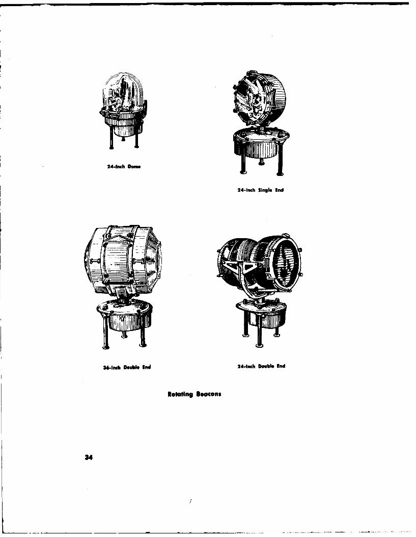
24-Inch Dome
24-Inch Single End
36-inch Double Ind 24-Inch Double End
Rotating Boacons
34

A
iAA
A-Not more than 150 ft.
Painting and Lighting of Towers, Poles and Similar Obstructions
35

S~A~i
I3
3
2 I
AA
3
•-j A
A
A-More than 150 ft. but A-More ihan 300 ft. butnot more IOwn 300 ft. not more than 450 ft.
Painting and Ughting of Towers and Similar Obstructions
36

ADA � SAHOUH UUMOA
* I � fl�HI; H III .1
.1* I I I I 0I II =I I .2
� E�
Ij!SI, � .3
3-0
I -I I £II I U�
�I I I C
II .2�1�
-
� II I I
''I[II�I I:1
S
37
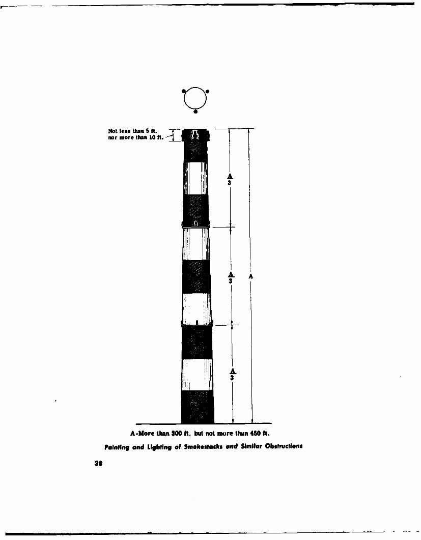
aNot less than 5 ft.nor more than 10 ft.
A3
A A3
A.3L_:_
A-More than 300 ft. but not more than 450 ft.
Painting and Lighting of Smokestacks and Similar Obstructions
31

t�a S ft.t�a lOft.-I-
0
IpseW d�
a.,ucthom lighi
A
A-U.S ass. t�m 210 ft.
Ssesp.nulen Type Obiftucti.. Light InsISII@t1
39

t
!3I--.-.3------
d A
tA
I
LIOYDIG MARIDN UGRYDIG MAREMI
A-Mure tihm 150 ft. hlo A ad 3- 15 ft. A md 3-Not more A-5 ft. or moremot more iem 200 ft. or more iUm 10 ft. 3-L=en thm 11 ft.
3-Not more Um 190 ft.
Painting and Ughting of Water Towers and Similar Obstructions
40

i3
iA
UGETM MAREM
A-More thin 150 ft. bet A and D- 15 ft. orow more thin M ft. more
31-lb more tihan 10 ft.
Painting and Lighting of Water Towers and Similar ObstrUdions
41

AA
A
LIGHTING MARUKN UGHTINO MARKINGA-Nore than 160 ft. but A and 3-15 ft. or more A and 3-Not more A-S ft. or more
not more than 300 ft. tuan 150 ft. 3- Lesa *tAn I ft.B-Not more thAn 150 ft.
Painting and Lighting of Gas Holders and Similar Obstructions
42
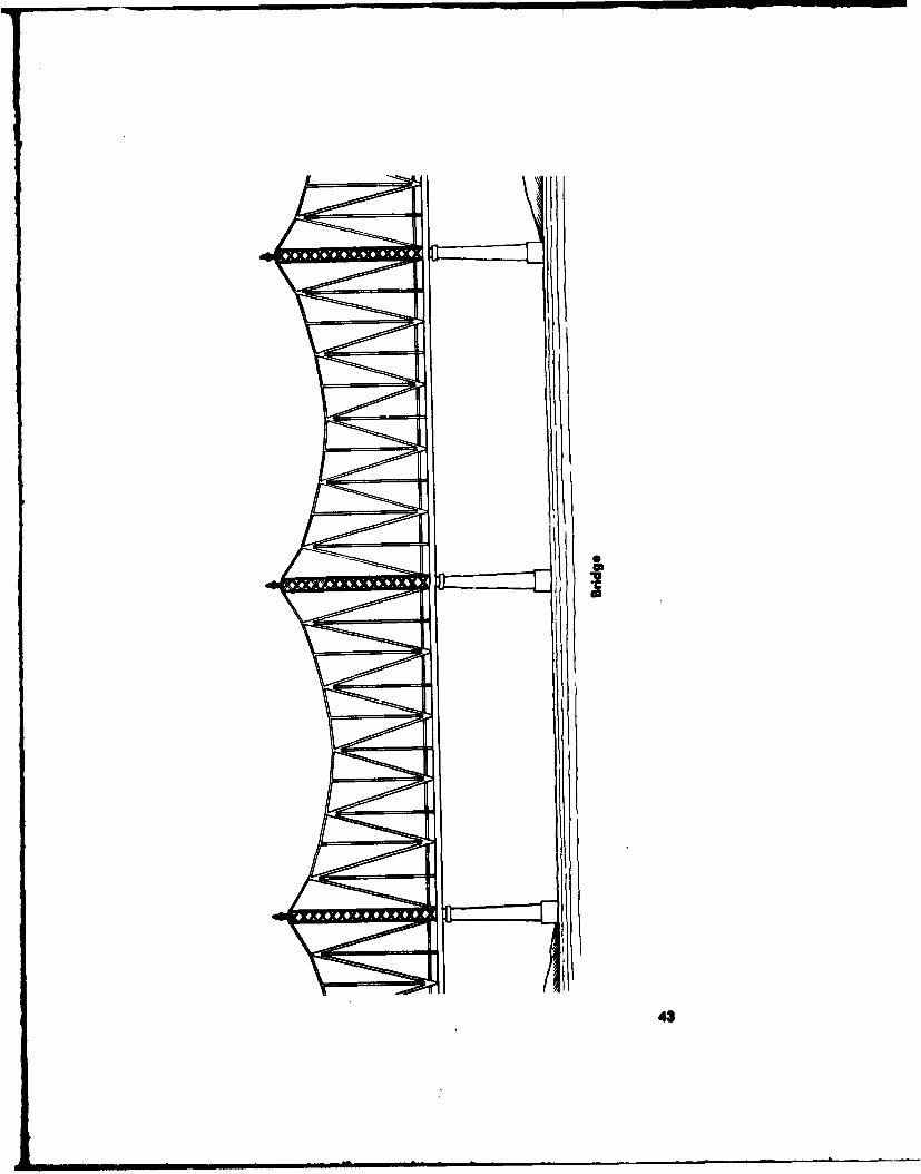
r l
43
15M
Hazard Area Day Marker
Hazard Ara- Marking
44O~ m a i -W