Advances in 2G HTS Conductor for High Field ApplicationsLTHFSW+SuperPo… · Advances in 2G HTS...
23
superior performance. powerful technology. SuperPower Inc. is a subsidiary of Furukawa Electric Co. Ltd. Advances in 2G HTS Conductor for High Field Applications DW Hazelton November 5, 2013 LTHFSW 2013 St. Petersburg, FL
Transcript of Advances in 2G HTS Conductor for High Field ApplicationsLTHFSW+SuperPo… · Advances in 2G HTS...
superior performance. powerful technology.
SuperPower Inc. is a subsidiary of Furukawa Electric Co. Ltd.
Advances in 2G HTS Conductor for High Field Applications
DW Hazelton
November 5, 2013 LTHFSW 2013 St. Petersburg, FL
LTHFSW 2013 St. Petersburg, FL November 5, 2013All Rights Reserved. Copyright SuperPower® Inc. 2013
Acknowledgements
2
• We would like to acknowledge the contributions of the team at SuperPower as well as collaborators from around the world.
• In particular we would like to acknowledge the input from Toru Fukushima, Paul Brownsey, Honghai Song*, Yifei Zhang, Justin Waterman, Trudy Lehner, Hisaki Sakamoto, John Dackow, Ross McClure and Allan Knoll.
• The work presented here is supported in part with funding from the US DOE Smart Grid Program and ARPA-E.
*currently at MSU-FRIB
LTHFSW 2013 St. Petersburg, FL November 5, 2013All Rights Reserved. Copyright SuperPower® Inc. 2013
Outline
• SuperPower 2G HTS conductor architecture• Critical current status• Mechanical properties• Bonded conductor development• Closing remarks
3
LTHFSW 2013 St. Petersburg, FL November 5, 2013All Rights Reserved. Copyright SuperPower® Inc. 2013 4
Wire performance critical to high field applications• Ic(B, T, )
– Temperature, magnetic field and field orientation dependence of Ic– Minimum Ic at operating condition
• Mechanical properties (electromechanical performance)– Workability for fabrication into various devices– Irreversible stress or strain limits under various stress condition, in terms
of Ic• Uniformity along length (Ic and other attributes)• Thermal properties (thermal expansion coefficient and thermal conductivity)• Quench stability (NZPV and MQE)• Insulation (material and method)• Splices
– Resistance (resistivity)– Mechanical strength (tensile and bending)

LTHFSW 2013 St. Petersburg, FL November 5, 2013All Rights Reserved. Copyright SuperPower® Inc. 2013
• Hastelloy® C276 substrate• high strength• high resistance• non-magnetic
• Buffer layers with IBAD-MgO • Diffusion barrier to metal substrate• Critical texture layer• Ideal lattice matching from substrate through ReBCO
• MOCVD grown ReBCO layer with BZO nanorods• Flux pinning sites for high in-field Ic
• Silver and copper stabilization
SuperPower’s ReBCO superconductor with artificial pinning structure provides a solution for demanding applications
5

LTHFSW 2013 St. Petersburg, FL November 5, 2013All Rights Reserved. Copyright SuperPower® Inc. 2013
Ic uniformity along length (TapeStar)
6
Position (cm) (on a 12 mm wide tape)
• Magnetic, non-contact measurement• High spacial resolution, high speed, reel-to-reel• Monitoring Ic at multiple production points after MOCVD• Capability of quantitative 2D uniformity inspection
LTHFSW 2013 St. Petersburg, FL November 5, 2013All Rights Reserved. Copyright SuperPower® Inc. 2013
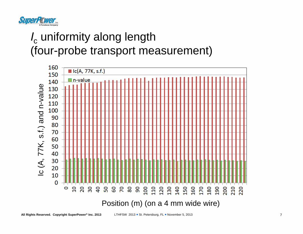
Ic uniformity along length (four-probe transport measurement)
7
Position (m) (on a 4 mm wide wire)
Ic (A
, 77K
, s.f.
) and
n-v
alue
LTHFSW 2013 St. Petersburg, FL November 5, 2013All Rights Reserved. Copyright SuperPower® Inc. 2013
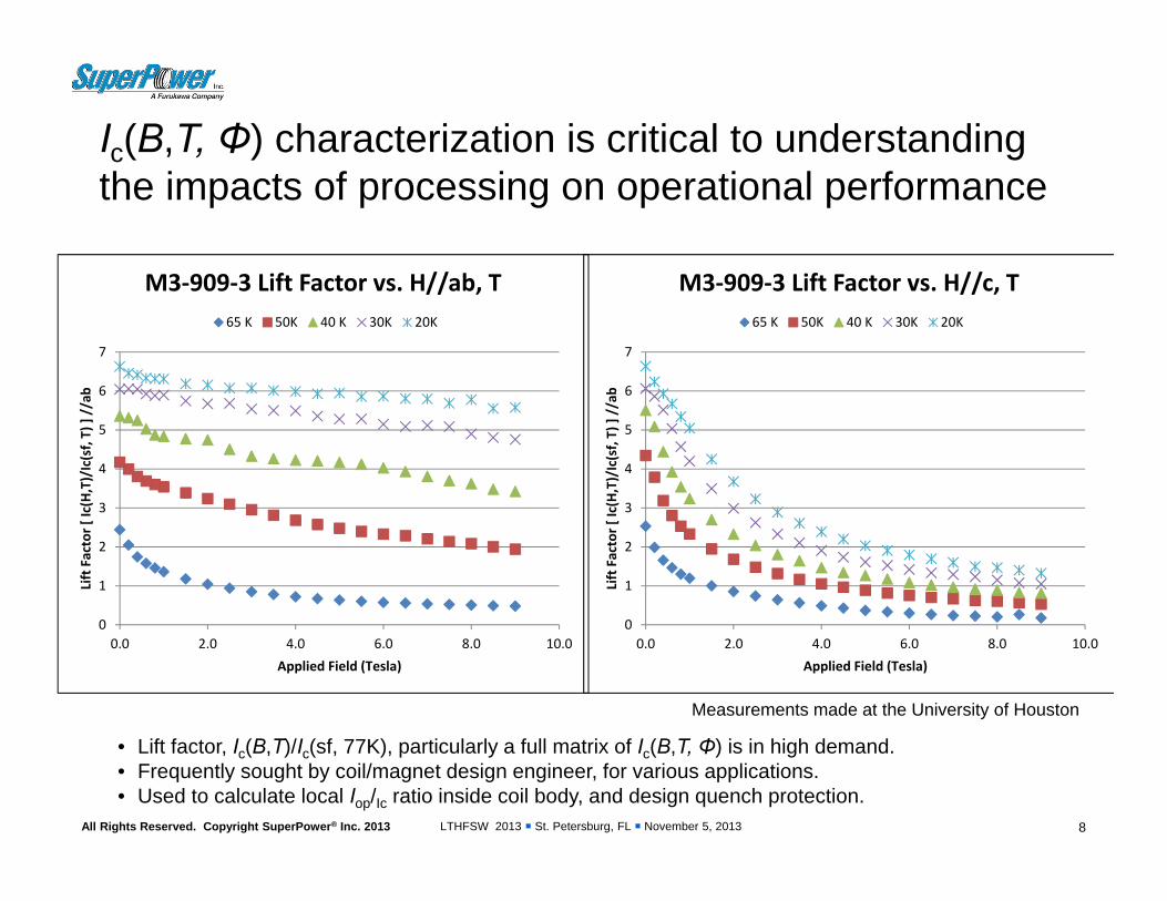
Ic(B,T, Φ) characterization is critical to understanding the impacts of processing on operational performance
8
Measurements made at the University of Houston
• Lift factor, Ic(B,T)/Ic(sf, 77K), particularly a full matrix of Ic(B,T, Φ) is in high demand.• Frequently sought by coil/magnet design engineer, for various applications.• Used to calculate local Iop/Ic ratio inside coil body, and design quench protection.
0
1
2
3
4
5
6
7
0.0 2.0 4.0 6.0 8.0 10.0
Lift Factor [ Ic(H,T)/Ic(sf, T) ] //ab
Applied Field (Tesla)
M3‐909‐3 Lift Factor vs. H//ab, T65 K 50K 40 K 30K 20K
0
1
2
3
4
5
6
7
0.0 2.0 4.0 6.0 8.0 10.0
Lift Factor [ Ic(H,T)/Ic(sf, T) ] //ab
Applied Field (Tesla)
M3‐909‐3 Lift Factor vs. H//c, T65 K 50K 40 K 30K 20K
LTHFSW 2013 St. Petersburg, FL November 5, 2013All Rights Reserved. Copyright SuperPower® Inc. 2013
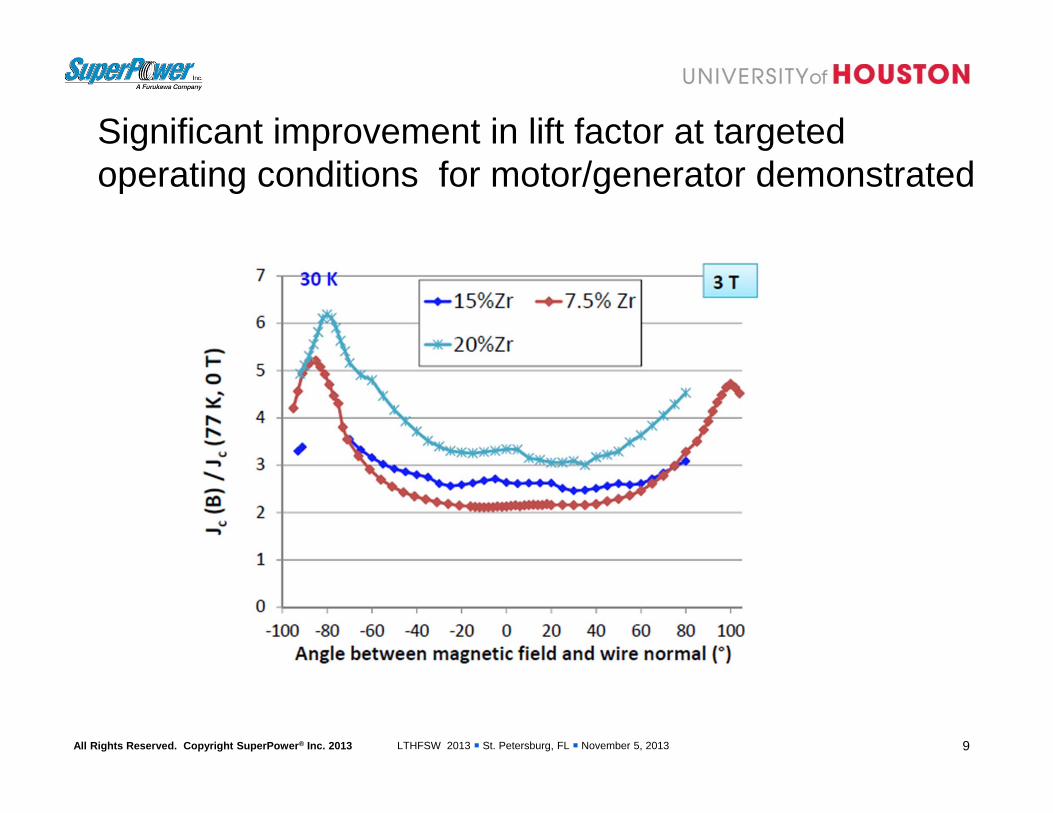
Significant improvement in lift factor at targeted operating conditions for motor/generator demonstrated
9

LTHFSW 2013 St. Petersburg, FL November 5, 2013All Rights Reserved. Copyright SuperPower® Inc. 2013
FEC Nikko test data – 4K Ic data
10
Ic test data• 4mm samples• B//c• Ic spread at
15T > 2x97.3 -195.1 A
for M3 (8 runs)• Tighter Ic
spread for M4205 – 229.4(2 runs)
• slopes comparable(0.64 – 0.75)
• M4 Ic > M3 Ic
LTHFSW 2013 St. Petersburg, FL November 5, 2013All Rights Reserved. Copyright SuperPower® Inc. 2013
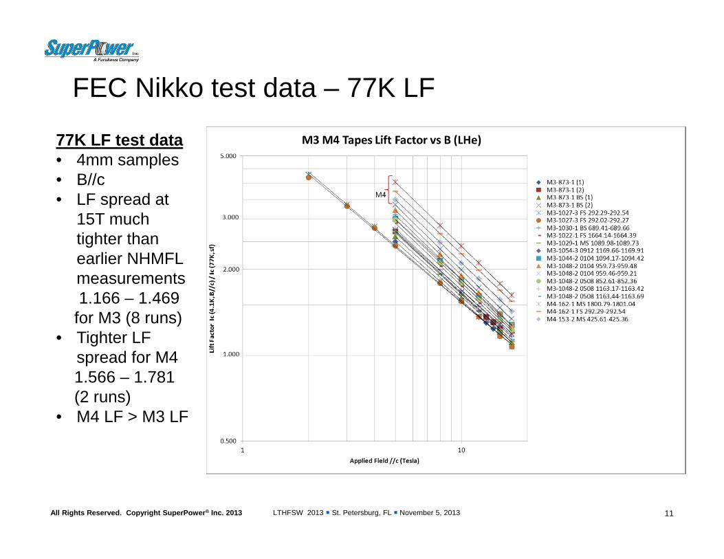
FEC Nikko test data – 77K LF
11
77K LF test data• 4mm samples• B//c• LF spread at
15T much tighter than earlier NHMFL measurements1.166 – 1.469
for M3 (8 runs)• Tighter LF
spread for M41.566 – 1.781(2 runs)
• M4 LF > M3 LF
LTHFSW 2013 St. Petersburg, FL November 5, 2013All Rights Reserved. Copyright SuperPower® Inc. 2013
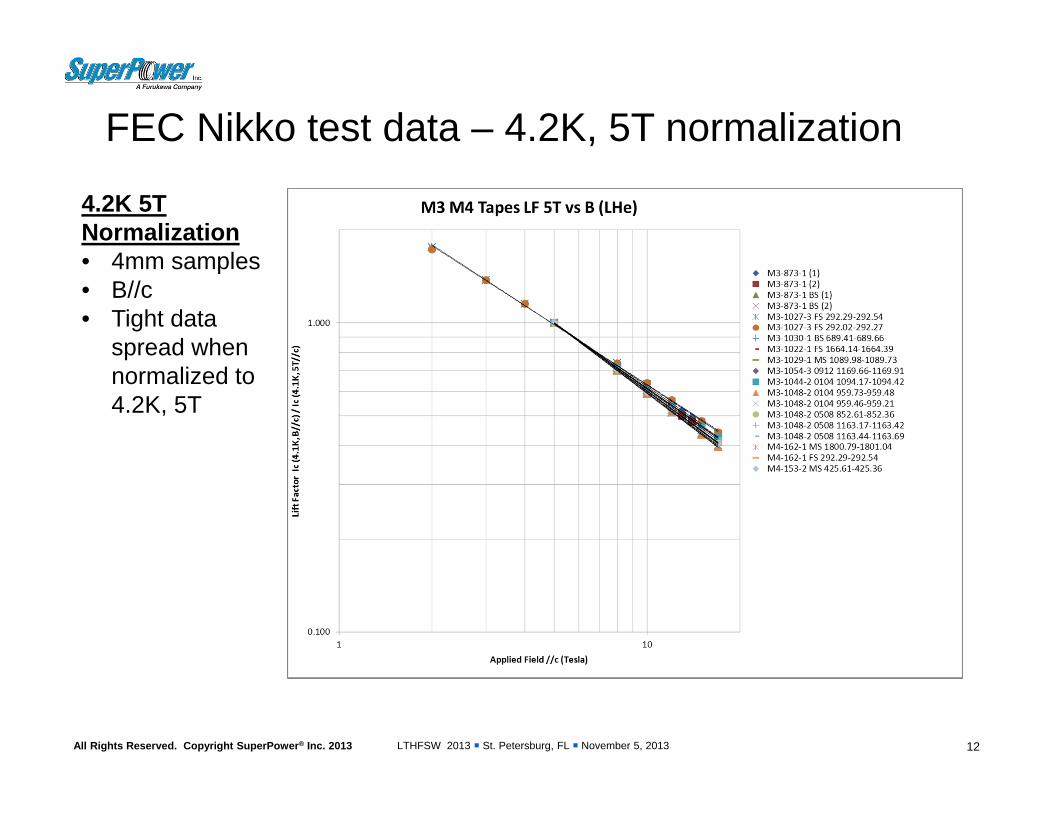
FEC Nikko test data – 4.2K, 5T normalization
12
4.2K 5TNormalization• 4mm samples• B//c• Tight data
spread when normalized to 4.2K, 5T

LTHFSW 2013 St. Petersburg, FL November 5, 2013All Rights Reserved. Copyright SuperPower® Inc. 2013
Lift factor performance tied to film composition
13
Composition X
1037A
807A774A
442A
795A373A
30K, 3T
Similar 4K, 15T analysis in progress

LTHFSW 2013 St. Petersburg, FL November 5, 2013All Rights Reserved. Copyright SuperPower® Inc. 2013
IcBT measurement system being built for routine production samplingTarget operating conditions
– Temperature: 30K – 77K– Field: 0 – 2.5T (65K)
• Higher field operation at 4K – Field //c and //ab (rotatable 0-225
deg)– Sample length in field – min 25
mm– Maximum sample current 800-
1200A• Full width samples to 4mm
wide – Maximum coil current 400A
• 2G HTS background coils– Enables testing of production
material in Schenectady (77K-30K, 0-2.5T) to evaluate consistency of lift factor.
14

LTHFSW 2013 St. Petersburg, FL November 5, 2013All Rights Reserved. Copyright SuperPower® Inc. 2013
Tensile test of Hastelloy substrates before EP• Substrates with various thickness measured for baseline data• 1.0mil, 1.2 mil, 1.5mil, 2mil, 4mil from Suppliers A, B
25.4 m per mil
LTHFSW 2013 St. Petersburg, FL November 5, 2013All Rights Reserved. Copyright SuperPower® Inc. 2013
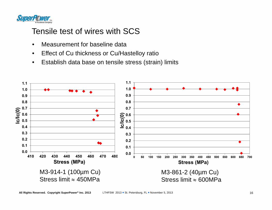
Tensile test of wires with SCS
16
• Measurement for baseline data• Effect of Cu thickness or Cu/Hastelloy ratio• Establish data base on tensile stress (strain) limits
M3-914-1 (100µm Cu)Stress limit 450MPa
M3-861-2 (40µm Cu)Stress limit 600MPa
LTHFSW 2013 St. Petersburg, FL November 5, 2013All Rights Reserved. Copyright SuperPower® Inc. 2013
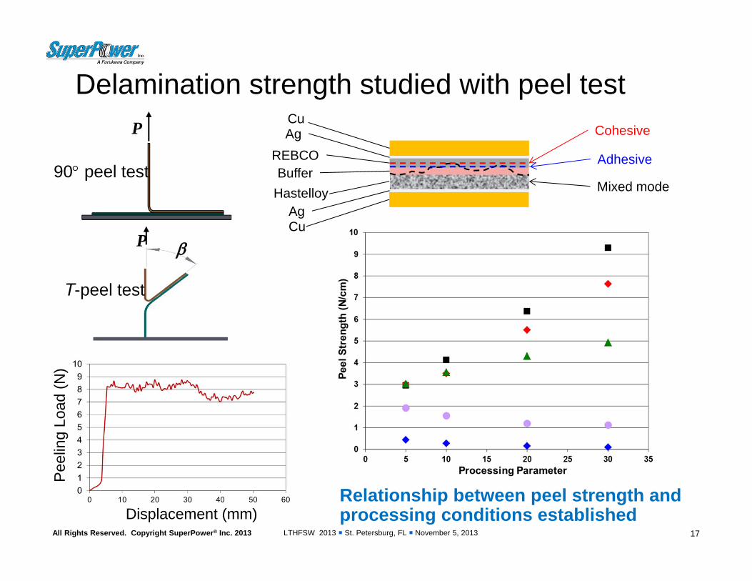
Cu
REBCOBuffer
Hastelloy
Cu
Cohesive
Adhesive
Mixed mode
Ag
Ag
Delamination strength studied with peel test
17
P
T-peel test
90 peel test
P
Displacement (mm)
Pee
ling
Load
(N)
Relationship between peel strength and processing conditions established
LTHFSW 2013 St. Petersburg, FL November 5, 2013All Rights Reserved. Copyright SuperPower® Inc. 2013
Successful winding techniques demonstrated to mitigate delamination issue • Decoupling of former from winding has been demonstrated to be
beneficial– Eliminates radial tensile stress on the 2G HTS windings– PET release layer incorporated at former:windings interface– Lower thermal expansion formers (Ti, controlled expansion glass-
epoxy)• Alternative insulations/epoxy systems have been successfully
demonstrated– PET shrink tube - NHMFL– Electrodeposited polyimide - Riken– Alternative epoxy system with filler - KIT
• Use of cowound stainless steel as “insulation” with partial epoxy application on coil sides – Mitigates radial tensile stress on the 2G HTS – Improves overall coil strength– Negative impact on coil current density
18

LTHFSW 2013 St. Petersburg, FL November 5, 2013All Rights Reserved. Copyright SuperPower® Inc. 2013
Stainless steel insulation, partial epoxy application on coil sides shows resistance to delamination
19
• Very thin layer of epoxy (transparent) after epoxy is cured
• Mechanical fix turn-turn and layer-layer
• Provides thermal link between optional cooling plates and windings
• Seals the coil
-2.00E-03
0.00E+00
2.00E-03
4.00E-03
6.00E-03
8.00E-03
1.00E-02
0 10 20 30 40 50
Vol
tage
(V)
Current (A)
TC#1
TC#2
TC#3
TC#4
TC#5
Five thermal cycles (77K), no degradation found
LTHFSW 2013 St. Petersburg, FL November 5, 2013All Rights Reserved. Copyright SuperPower® Inc. 2013
0.0E+00
2.0E‐04
4.0E‐04
6.0E‐04
8.0E‐04
1.0E‐03
1.2E‐03
1.4E‐03
0 10 20 30 40 50
Volta
ge over 1
0 meter (V
)
Current (A)
TC#5 TC#4 TC#3 TC#2 TC#1
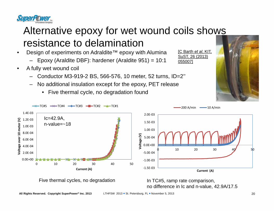
Alternative epoxy for wet wound coils shows resistance to delamination
• Design of experiments on Adraldite™ epoxy with Alumina– Epoxy (Araldite DBF): hardener (Araldite 951) = 10:1
• A fully wet wound coil– Conductor M3-919-2 BS, 566-576, 10 meter, 52 turns, ID=2’’– No additional insulation except for the epoxy, PET release
• Five thermal cycle, no degradation found
20
Ic=42.9A, n-value=~18
Five thermal cycles, no degradation
‐1.5E‐03
‐1.0E‐03
‐5.0E‐04
0.0E+00
5.0E‐04
1.0E‐03
1.5E‐03
2.0E‐03
0 10 20 30 40 50Volta
ge (V
)
Current (A)
200 A/min 10 A/min
In TC#5, ramp rate comparison, no difference in Ic and n-value, 42.9A/17.5
[C Barth et al, KIT, SuST. 26 (2013) 055007]
LTHFSW 2013 St. Petersburg, FL November 5, 2013All Rights Reserved. Copyright SuperPower® Inc. 2013
Capability for bonded conductors demonstrated [higher amperage, specialty applications (FCL) ]
21
• Bonded conductors offer the ability to achieve higher operating currents– FCL transformer windings– HEP applications– High current bus applications
• Bonded conductors offer higher strength – Withstand FCL transformer fault currents– High field HEP applications with high force loadings
• Bonded conductors offer the ability to tailor application specific operating requirements, i.e. normal state resistance for a FCL transformer
LTHFSW 2013 St. Petersburg, FL November 5, 2013All Rights Reserved. Copyright SuperPower® Inc. 2013 22
0.000
0.020
0.040
0.060
0.080
0.100
0.120
0.140
0 100 200 300 400 500
resi
stan
ce /
leng
th (o
hm /
m)
temperature (K)
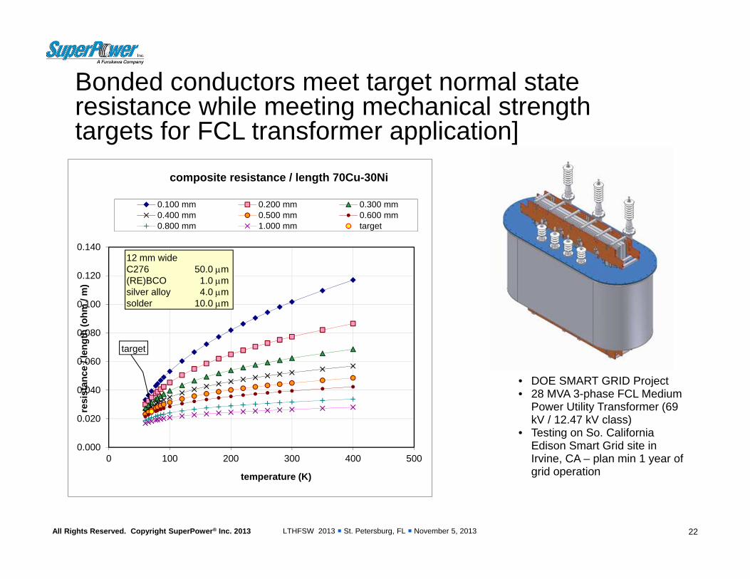
composite resistance / length 70Cu-30Ni
0.100 mm 0.200 mm 0.300 mm0.400 mm 0.500 mm 0.600 mm0.800 mm 1.000 mm target
12 mm wideC276 50.0 m(RE)BCO 1.0 msilver alloy 4.0 msolder 10.0 m
target
Bonded conductors meet target normal state resistance while meeting mechanical strength targets for FCL transformer application]
• DOE SMART GRID Project• 28 MVA 3-phase FCL Medium
Power Utility Transformer (69 kV / 12.47 kV class)
• Testing on So. California Edison Smart Grid site in Irvine, CA – plan min 1 year of grid operation

LTHFSW 2013 St. Petersburg, FL November 5, 2013All Rights Reserved. Copyright SuperPower® Inc. 2013
Closing remarks
• SuperPower 2G HTS conductor offers a flexible architecture to address the broad range of demanding high field applications requirements.
• SuperPower is engaging major resources in improving its manufacturing capabilities to deliver a consistent, reliable, high quality 2G HTS product– Improved mechanical properties– Improved piece length / uniformity– Improved current density– Improved splice resistance
• Alternative conductor configurations are being developed to address customer specific requirements– Ag alloy– Bonded conductors
23