ADVANCEMENT IN AUTOMOTIVE NIGHT VISION SYSTEM
44
ADVANCEMENT IN AUTOMOTIVE NIGHT VISION SYSTEM - M42MAE 1 ADVANCEMENT IN AUTOMOTIVE NIGHT VISION SYSTEM Submitted by, SHIHABUDEEN RAJELA IMRAN Student ID-5914621
-
Upload
imran-shihabudeen-rajela -
Category
Documents
-
view
176 -
download
1
Transcript of ADVANCEMENT IN AUTOMOTIVE NIGHT VISION SYSTEM
ADVANCEMENT IN AUTOMOTIVE NIGHT VISION SYSTEM - M42MAE
1
ADVANCEMENT IN AUTOMOTIVE NIGHT VISION
SYSTEM
Submitted by,
SHIHABUDEEN RAJELA IMRAN
Student ID-5914621
ADVANCEMENT IN AUTOMOTIVE NIGHT VISION SYSTEM - M42MAE
2
SUMMARY
Night vision is one of the major advancement in vehicle safety systems. It enables
the better visibility of the field in which vehicle is driven during the night time. Studies
report that, there is only quarter of the all travel by car drivers is undertaken a night drive,
but still, 40% of the road accidents happens during night time. This makes night vision
system demanding for drivers assist during poor light or during night time.
The major reason for night accidents is poor visibility of the field of driving due to the
limitation in head light range and the dazzling of high beam headlight from the vehicle that
approaches from the opposite direction. Though night vision system available in the market
minimizes the occurrence and consequences of automobile accidents, it is not 100%
efficient for the ease and pleasure of driving for the old aged drivers. Since its display is
limited to a small screen which provides only a monochrome output, the driver doesn't tent
to depend on night vision all the time.
With this paper work we are trying to highlight the advancement of night vision which can
convert the present monochromatic display to a colourised one and help driver with a better
assist.
ADVANCEMENT IN AUTOMOTIVE NIGHT VISION SYSTEM - M42MAE
3
ACKNOWLEDGEMENTS
Our endeavour stands incomplete without dedicating our sincere gratitude to
everyone who has helped a lot towards the successful completion of our course work. First
of all we offer our thanks to for their blessings. We are indebted to God Almighty for
blessing us with his grace and taking our dream to a successful completion. We specially
acknowledge our tutor guide Yuri Vershinin for the guidance given to us and steering us to
the successful completion of our coursework in time.
ADVANCEMENT IN AUTOMOTIVE NIGHT VISION SYSTEM - M42MAE
4
TABLE OF CONTENTS:
INTRODUCTION ..................................................................................................................6
1.NIGHT VISION SYSYTEM ............................................................................................6
2.NIGHT VISION SYSTEM I AUTOMOBILE.................................................................7
2.1 INFRARED PROJECTORS......................................................................................8
2.2 NIGHT VISION CAMERA.....................................................................................9
2.3 IMAGE INTENSIFIER............................................................................................9
2.4 INFRARED SENSORS..........................................................................................11
2.5 NIGHT VISION PROCESSING UNIT..................................................................12
3. WORKING OF AUTOMOTIVE NIGHT VISION SYSTEM.......................................13
4. ADVANCEMENT IN NIGHT VISION SYSTEM........................................................14
4.1 PEDESTRIAN DETECTION SYSTEM................................................................14
4.1.1 CHARACTERSTICS OF IR DOMAIN...........................................................15
4.1.2 WORKING OF PEDESTRIAN DETECTION SYSTEM...............................15
4.1.3 PEDESTRIAN DETECTION ALGORITHM..................................................17
4.1.3.1 CONTOUR BASED CANDIDATE AREA EXTRACTION...........18
4.1.3.2 CANDIDATE AREA CLASSIFICATION.......................................21
4.1.3.3 CANDIDATE AREA TRACKING...................................................22
4.2 INTELLIGENT VISION FOR AUTOMOBILES AT NIGHT..............................22
4.2.1 WORKING OF IVAN......................................................................................25
4.3 TRUE COLOR NIGHT VISION............................................................................30
4.3.1 DESCRIPTION OF CAMERAS......................................................................32
4.3.1.1 LIQUID CRYSTAL FILTER INTENSIFIED CAMERA................32
4.3.1.2 EMCCD/MOSAIC CAMERA..........................................................34
4.3.2 FUSION FOR TRUE COLOR NIGHT VISION.............................................36
CONCLUSION.....................................................................................................................39
5. DISCUSSION...............................................................................................................39
6. CONCLUSION.............................................................................................................41
7. RECOMENDATIONS..................................................................................................42
SUPPORTING MATERIALS...............................................................................................43
8. REFERENCES..............................................................................................................43
9. BIBLOGRAPHY.........................................................................................................44
10. APPENDIX..................................................................................................................44
ADVANCEMENT IN AUTOMOTIVE NIGHT VISION SYSTEM - M42MAE
5
TABLE OF FIGURES:
IMAGE 1: INFRARED PROJECTOR....................................................................................8
IMAGE 2 : NIGHT VISION CAMERA.................................................................................9
IMAGE 3: IMAGE INTENSIFIER.......................................................................................10
IMAGE 4 : PATH OF PHOTON MULTIPLIER..................................................................11
IMAGE 5 : INFRARED SENSORS......................................................................................11
IMAGE 6 : NIGHT VISION PROCESSING UNIT.............................................................11
IMAGE 7 : NIGHT VISION SYSTEM IN A CAR..............................................................13
IMAGE 8 : CIRCUIT DIAGRAM OF NIGHT VISION SYSTEM.....................................13
IMAGE 9 : AUTOMOTIVE PEDESTRIAN DETECTION SYSTEM................................16
IMAGE 10 : FLOW CHART OF PEDESTRIAN DETECTION SYSTEM.........................16
IMAGE 11 : FLOW CHART PEDESTRIAN DETECTION ALGORITHM.......................17
IMAGE 12 : IMAGE EXTRACTED CONTOUR................................................................18
IMAGE 13 : DIVIDE OF CONTOUR GROUP...................................................................19
IMAGE 14 : DIVIDE OF CONTOUR GROUP...................................................................20
IMAGE 15 : GROUPING OF BODY PART........................................................................20
IMAGE 16 : SYSTEM OVERVIEW OF IVAN...................................................................23
IMAGE 17 : IMAGE FROM DIFFERENT CAMERA........................................................24
IMAGE 18 : IVAN SYSTEM................................................................................................25
IMAGE 19 : IVAN ELLIPSE VERIFICATION PROCESS................................................26
IMAGE 20 : DETECTION STABLIZATION ALGORITHM.............................................27
IMAGE 21 : ROAD SIGN IMAGE ENHANCEMENT.......................................................27
IMAGE 22 : ROAD SIGN FEATURE EXTRACTION.......................................................28
IMAGE 23 : ADAPTIVE INFRARED CAMERA...............................................................28
IMAGE 24 : SIMPLE CASE ROAD SIGN DETECTION...................................................29
IMAGE 25 : MONOCHROME &COLOR LOW LIGHT LEVEL IMAGERY...................31
IMAGE 26 : IMAGE TAKEN WITH TCNV CAMERAS...................................................31
IMAGE 27 : LIQUID CRYSTAL FILTER...........................................................................32
IMAGE 28 : TCVN PROTOTYPE WITH LC FILTER.......................................................34
IMAGE 29 : EMCCD/MOSAIC...........................................................................................35
IMAGE 30 : PLOT OF SPECTRAL RESPONSE................................................................38

ADVANCEMENT IN AUTOMOTIVE NIGHT VISION SYSTEM - M42MAE
6
INTRODUCTION:
1. NIGHT VISION SYSTEM.
Night vision system is the technology developed for the clear visibility of the field of an
object during the night time or under poor light. Night vision technology was first
developed for the military activities. Later on the technology was adopted in commercial
purpose such as for automobiles and aircrafts.
Night vision system works based on the infrared rays. Infrared rays are a property of light
which falls under the wavelength of 700 nanometre to 1 millimetre. The infrared rays are
divided into three categories; Near Infrared, Mid Infrared and Far Infrared or Thermal
Infrared. The key difference between Thermal-IR and the other two is that thermal-IR is
emitted by an object instead of reflected off it. Infrared light is emitted by an object because
of what is happening at the atomic level. Ever particle reflects light. While considering a
particle in its atomic level, when it is subjected to light, some particle absorb light in the
form of heat and some reflects it back at a varying wavelength. These reflected photons may
not come under the visible range of the humans, as human eyes have its limitations when
compared to animal, but sensors can do. Also, anything that is alive uses energy, and so do
many inanimate items such as engines and rockets. Energy consumption generates heat. In
turn, heat causes the atoms in an object to fire off photons in the thermal-infrared spectrum.
The hotter the object, the shorter the wavelength of the infrared photon it releases. Thermal
imaging takes advantage of this infrared emission. An object that is very hot will even begin
to emit photons in the visible spectrum, glowing red and then moving up through orange,
yellow, blue and eventually white. These reflected and emitted radiations which come under
the infrared regions are detected by IR sensors and cameras to generate a monochromatic
image that gives a better visibility of the field of view during low light.
Presently, there are two types of Night Vision technologies on the market, Far Infrared
(FIR) and Near Infrared (NIR). As stated above, FIR detects the radiation which all objects
emit, while NIR detects the reflected illumination in a frequency just outside the visible
range of a human being. This paper will analyse the requirements of a Night Vision system,
how NIR and FIR today perform under the defined condition and proceed to discuss
directions for future development.
ADVANCEMENT IN AUTOMOTIVE NIGHT VISION SYSTEM - M42MAE
7
2. NIGHT VISION SYSTEM IN AUTOMOBILE
All cars today have an acceptable ‘night vision’ system. That is, the high beam headlights of
the vehicle. Even though they could be improved, their performances are at least acceptable.
However, in many areas, high beams are of very limited use due to oncoming traffic. The
insufficient night-time visibility originates in the fact that the high beam headlights are
rarely possible to use. A Night Vision system must therefore be a system that increases
visibility in situations where only low beam headlights can be used. Studies report that,
there is only quarter of the all travel by car drivers is undertaken a night drive, but still, 40%
of the road accidents happens during night time. This makes night vision system demanding
for drivers assist during poor light or during night time.
The major reason for night accidents is poor visibility of the field of driving due to the
limitation in low beam head light range and the dazzling of high beam headlight from the
vehicle that approaches from the opposite direction. Though night vision system available
in the market minimizes the occurrence and consequences of automobile accidents, it is not
100% efficient for the ease and pleasure of driving for the old aged drivers. This condition
thus define the importance and need to implicated technologies for the safety of pedestrians
during the night time, and better aid for the driver to understand his field of view at a
comfortable level.
The short detection distances for especially dark objects under low beam conditions versus
the corresponding situation under high beam condition illustrate the detection distance
deficiency that a Night Vision system should overcome. Safe driving speed should allow the
driver to detect, react and stop in time before any obstacles on the road. However, most
motorists actually drive faster than the visibility range allow with low beam headlights.

ADVANCEMENT IN AUTOMOTIVE NIGHT VISION SYSTEM - M42MAE
8
Table 1: Detection distances to dark vertical objects, typical for present realistic night
driving conditions
The present night vision system used is automobile is a combination of NIR with image
intensifier and FIR with thermal imaging. The night vision system uses an infrared
projector, a camera, a processing unit and a display.
2.1 INFRARED PROJECTORS
Night vision system works on the principle of infrared rays. Infrared rays are invisible light
rays which a human eye cannot capture. These infrared rays are generated using infrared
LEDs and infrared laser beams. The LEDs are used for NIR system while the infrared laser
is used for FIR to get a long range view. Now, in modern cars with night vision system, the
infrared projectors are attached along with the head lights rather than being placed
separately.
Image 1: Infrared Projector
ADVANCEMENT IN AUTOMOTIVE NIGHT VISION SYSTEM - M42MAE
9
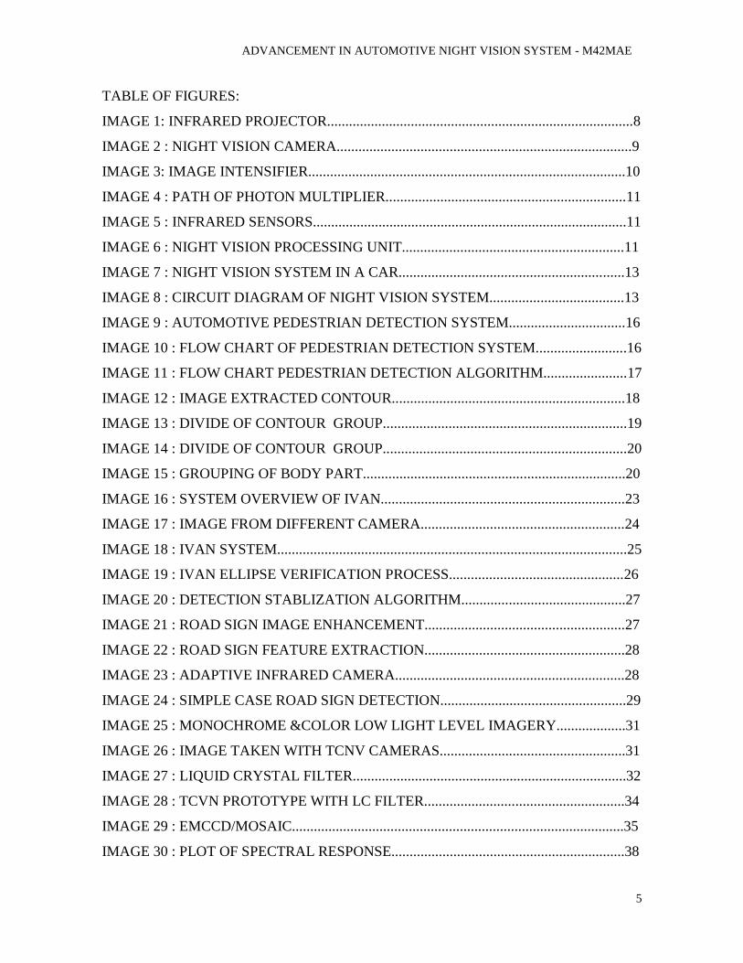
2.2 NIGHT VISION CAMERA
The present night vision cameras used in automobile applications are very compact and
easy to accommodate. Some car manufacturers make a built in night vision system in their
cars. But some offer it as an added choice for the customer.
Image 2: Night vision camera.
Like normal DSLR cameras, the night vision camera consist of a lens part often known as
image intensifier and a photon detecting sensor which can sense IR radiation.
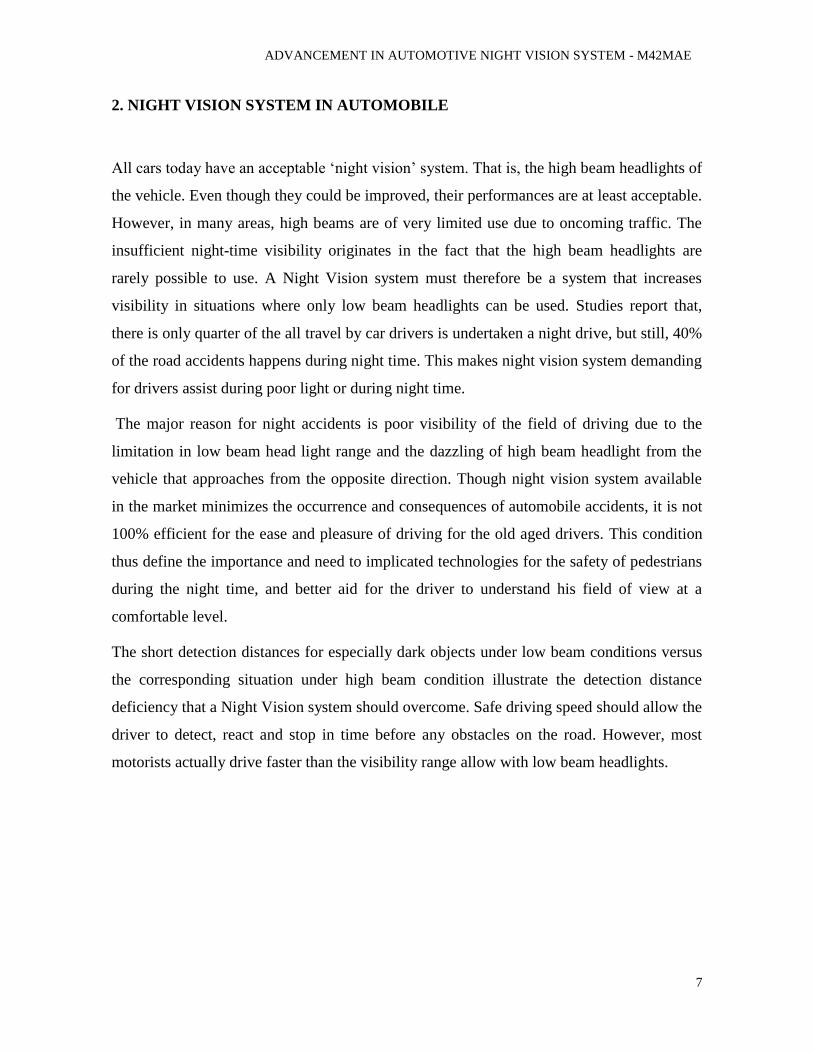
2.3 IMAGE INTENSIFIER
Image-enhancement technology is what most people think of when you talk about night
vision. In fact, image-enhancement systems are normally called night-vision
devices (NVDs). NVDs rely on a special tube, called an image-intensifier tube, to collect
and amplify infrared and visible light. In night vision system, a conventional lens, called
the objective lens, captures ambient light and some near-infrared light. The gathered light is
sent to the image-intensifier tube. The image-intensifier tube has a photocathode, which is
used to convert the photons of light energy into electrons. As the electrons pass through the
tube, similar electrons are released from atoms in the tube, multiplying the original number
ADVANCEMENT IN AUTOMOTIVE NIGHT VISION SYSTEM - M42MAE
10
of electrons by a factor of thousands through the use of a micro channel plate (MCP) in the
tube. A MCP is a tiny glass disc that has millions of microscopic holes (micro channels) in
it, made using fibre-optic technology. The MCP is contained in a vacuum and has metal
electrodes on either side of the disc. Each channel is about 45 times longer than it is wide,
and it works as an electron multiplier. When the electrons from the photo cathode hit the
first electrode of the MCP, they are accelerated into the glass micro channels by the 5,000-
V bursts being sent between the electrode pair. As electrons pass through the micro
channels, they cause thousands of other electrons to be released in each channel using a
process called cascaded secondary emission. Basically, the original electrons collide with
the side of the channel, exciting atoms and causing other electrons to be released. These
new electrons also collide with other atoms, creating a chain reaction that results in
thousands of electrons leaving the channel where only a few entered. An interesting fact is
that the micro channels in the MCP are created at a slight angle (about a 5-degree to 8-
degree bias) to encourage electron collisions and reduce both ion and direct-light feedback
from the phosphors on the output side. At the end of the image-intensifier tube, the
electrons hit a screen coated with phosphors. These electrons maintain their position in
relation to the channel they passed through, which provides a perfect image since the
electrons stay in the same alignment as the original photons. The energy of the electrons
causes the phosphors to reach an excited state and release photons. These phosphors create
the green image on the screen that has come to characterize night vision. The green
phosphor image is viewed through another lens, called the ocular lens, which allows you to
magnify and focus the image. The NVD may be connected to an electronic display, such as
a monitor, or the image may be viewed directly through the ocular lens.
Image 3: Photon multiplying phenomenon of the photon received in image intensifier
ADVANCEMENT IN AUTOMOTIVE NIGHT VISION SYSTEM - M42MAE
11
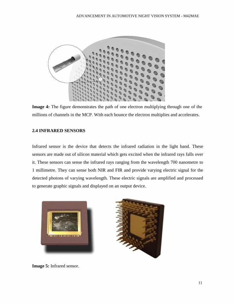
Image 4: The figure demonstrates the path of one electron multiplying through one of the
millions of channels in the MCP. With each bounce the electron multiplies and accelerates.
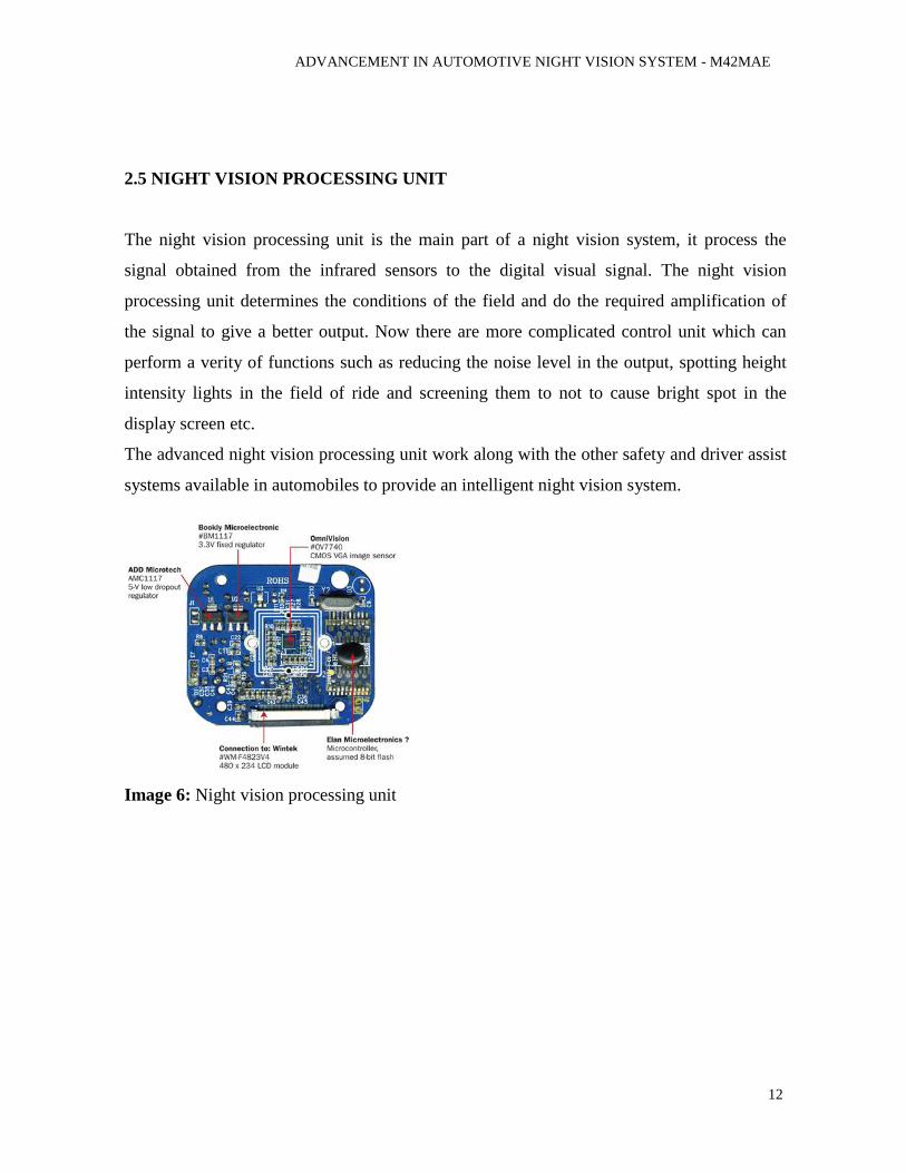
2.4 INFRARED SENSORS
Infrared sensor is the device that detects the infrared radiation in the light band. These
sensors are made out of silicon material which gets excited when the infrared rays falls over
it. These sensors can sense the infrared rays ranging from the wavelength 700 nanometre to
1 millimetre. They can sense both NIR and FIR and provide varying electric signal for the
detected photons of varying wavelength. These electric signals are amplified and processed
to generate graphic signals and displayed on an output device.
Image 5: Infrared sensor.
ADVANCEMENT IN AUTOMOTIVE NIGHT VISION SYSTEM - M42MAE
12
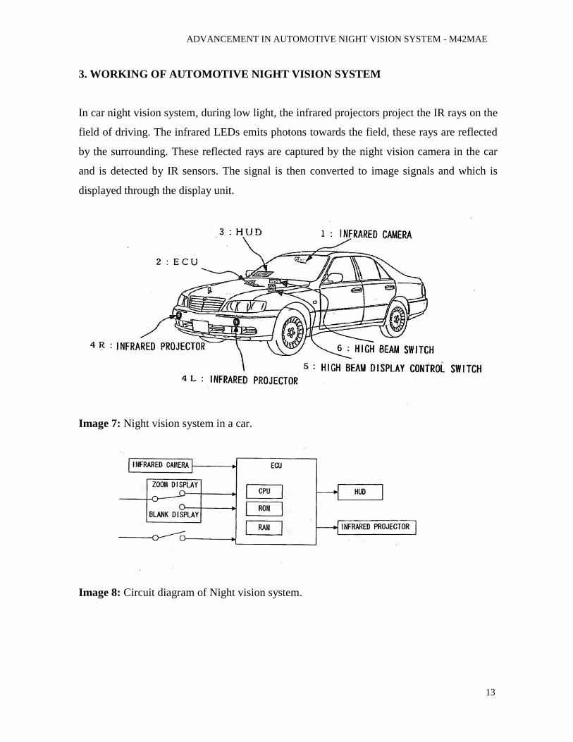
2.5 NIGHT VISION PROCESSING UNIT
The night vision processing unit is the main part of a night vision system, it process the
signal obtained from the infrared sensors to the digital visual signal. The night vision
processing unit determines the conditions of the field and do the required amplification of
the signal to give a better output. Now there are more complicated control unit which can
perform a verity of functions such as reducing the noise level in the output, spotting height
intensity lights in the field of ride and screening them to not to cause bright spot in the
display screen etc.
The advanced night vision processing unit work along with the other safety and driver assist
systems available in automobiles to provide an intelligent night vision system.
Image 6: Night vision processing unit
ADVANCEMENT IN AUTOMOTIVE NIGHT VISION SYSTEM - M42MAE
13
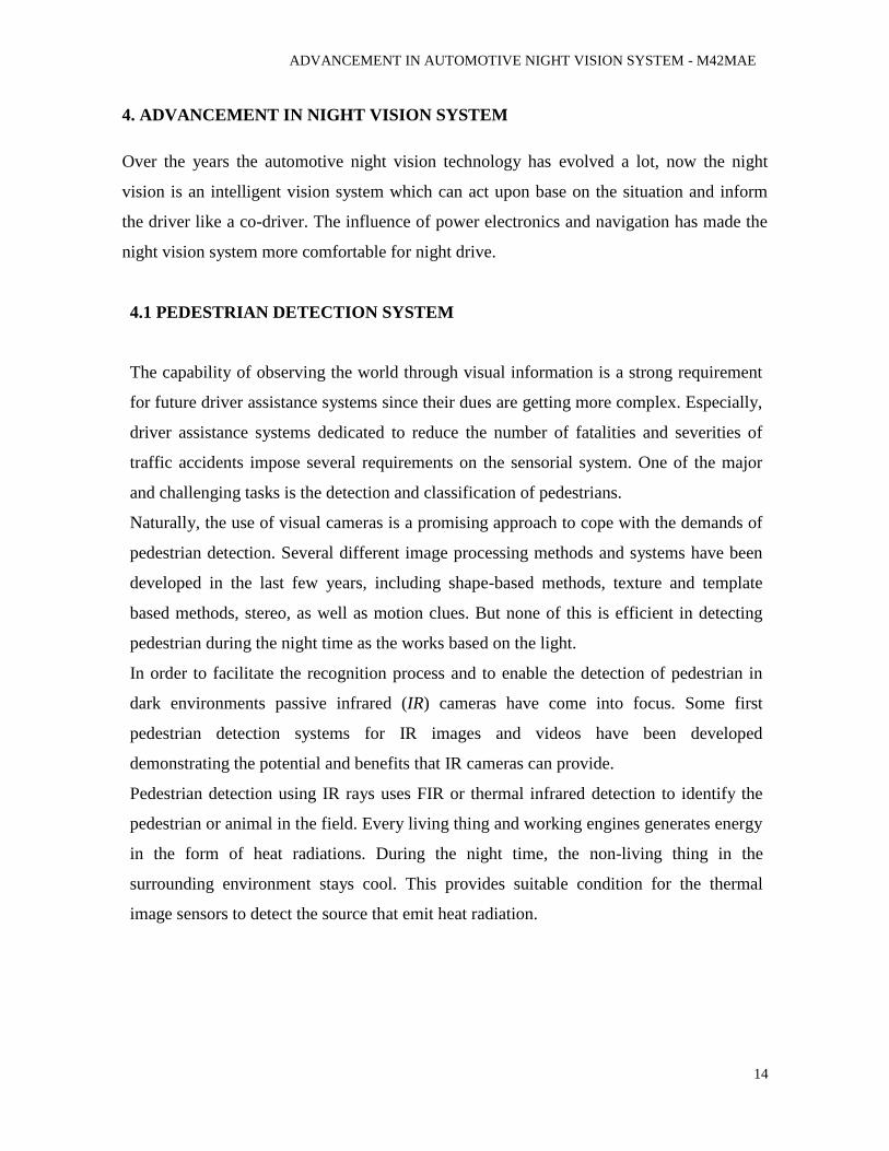
3. WORKING OF AUTOMOTIVE NIGHT VISION SYSTEM
In car night vision system, during low light, the infrared projectors project the IR rays on the
field of driving. The infrared LEDs emits photons towards the field, these rays are reflected
by the surrounding. These reflected rays are captured by the night vision camera in the car
and is detected by IR sensors. The signal is then converted to image signals and which is
displayed through the display unit.
Image 7: Night vision system in a car.
Image 8: Circuit diagram of Night vision system.
ADVANCEMENT IN AUTOMOTIVE NIGHT VISION SYSTEM - M42MAE
14
4. ADVANCEMENT IN NIGHT VISION SYSTEM
Over the years the automotive night vision technology has evolved a lot, now the night
vision is an intelligent vision system which can act upon base on the situation and inform
the driver like a co-driver. The influence of power electronics and navigation has made the
night vision system more comfortable for night drive.
4.1 PEDESTRIAN DETECTION SYSTEM
The capability of observing the world through visual information is a strong requirement
for future driver assistance systems since their dues are getting more complex. Especially,
driver assistance systems dedicated to reduce the number of fatalities and severities of
traffic accidents impose several requirements on the sensorial system. One of the major
and challenging tasks is the detection and classification of pedestrians.
Naturally, the use of visual cameras is a promising approach to cope with the demands of
pedestrian detection. Several different image processing methods and systems have been
developed in the last few years, including shape-based methods, texture and template
based methods, stereo, as well as motion clues. But none of this is efficient in detecting
pedestrian during the night time as the works based on the light.
In order to facilitate the recognition process and to enable the detection of pedestrian in
dark environments passive infrared (IR) cameras have come into focus. Some first
pedestrian detection systems for IR images and videos have been developed
demonstrating the potential and benefits that IR cameras can provide.
Pedestrian detection using IR rays uses FIR or thermal infrared detection to identify the
pedestrian or animal in the field. Every living thing and working engines generates energy
in the form of heat radiations. During the night time, the non-living thing in the
surrounding environment stays cool. This provides suitable condition for the thermal
image sensors to detect the source that emit heat radiation.
ADVANCEMENT IN AUTOMOTIVE NIGHT VISION SYSTEM - M42MAE
15
4.1.1 CHARACTERIZATION OF IR DOMAIN
Images in the IR domain convey a type of information very different from images in the
visible spectrum. In the IR domain the image of an object relates to its temperature and the
amount of heat it emits but is not affected by illumination changes.
Generally, the temperature of people is higher than the environmental temperature and their
heat radiation is sufficiently high compared to the background. Therefore, in IR images
pedestrians are bright and sufficiently contrasted with respect to the back-ground, thus
making IR imagery suited to their localization. Other objects which actively radiate heat
(cars, trucks etc.) have a similar behaviour; however people can be recognized thanks to
their shape and aspect ratio.
One major point in favour of IR cameras is the independency to lighting changes: IR
cameras can be used in day-time or night-time with no or little difference extending vision
beyond the usual limitations of day-light cameras. Moreover, the absence of colours or
strong textures eases the processing towards interpretation. Furthermore, the problem of
shadows is greatly reduced.
4.1.2. WORKING OF PEDESTRIAN DETECTION SYSTEM
The main deal with the pedestrian detection system is to identify the presence of
pedestrians or animal nearby the field of driving and to predict and inform and warn the
drive based on the behaviour of the identified object. For this, a serious of processing and
calculations are been done by the night vision control unit to determine the position,
behaviour and size of object. All these things are been done with the help of real time image
processing.
Since the vehicle is in continuous movement, tracking the position of the detected object
is a bit complicated task. For this the image processing unit uses multiple frames of images
at an in travel of time, and relates with the vehicle seed to determine the relative position of
the object.
The ratios of the polar coordinates of the detected images at consecutive intervals
determine the size and type of the identified object.
ADVANCEMENT IN AUTOMOTIVE NIGHT VISION SYSTEM - M42MAE
16
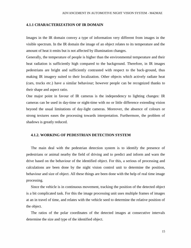
When an object is detected, a bounding box appears on the screen to indicate the position
of it in the output screen.
Image 9: Automotive Pedestrian detection system
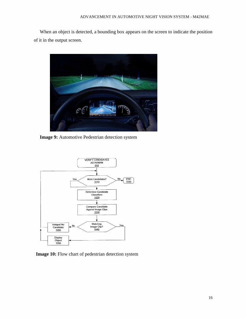
Image 10: Flow chart of pedestrian detection system

ADVANCEMENT IN AUTOMOTIVE NIGHT VISION SYSTEM - M42MAE
17
4.1.3. PEDESTRIAN DETECTION ALGORITHM
The process flowchart of the newly proposed pedestrian detection algorithm is shown in
Image 11. In many cases of night time pedestrian detection, processing methods based on
image binarization are used because the intensity (i.e. temperature) of pedestrians is higher
than that of background objects. However, at daytime or in bad weather, making
assumptions on the intensity is not always effective because of environmental influences on
FIR images (Table 2).
Image 11: Flow chart of pedestrian detection algorithm
Table 2: Features of FIR images
ADVANCEMENT IN AUTOMOTIVE NIGHT VISION SYSTEM - M42MAE
18
4.1.3.1 Contour-based candidate area extraction
The method of contour-based candidate area extraction uses the intensity difference
between a pedestrian and the background and a constrained condition of distances to
pedestrian body parts. The constrained condition is based on the assumption that the
distance between FIR camera and each pedestrian body part (head, arms, torso, and legs) is
the same. However, the contour of a pedestrian is not always a continuous line and is
usually disconnected at every parts of the body. Therefore, the candidate area extraction
method is made of two steps: (1) Extraction of body part areas, and (2) grouping of body
part areas, as shown below.
(a) Extraction of pedestrian body part areas
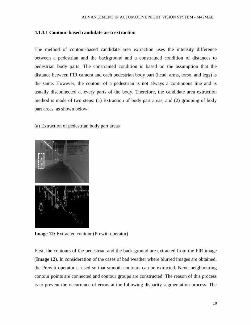
Image 12: Extracted contour (Prewitt operator)
First, the contours of the pedestrian and the back-ground are extracted from the FIR image
(Image 12). In consideration of the cases of bad weather where blurred images are obtained,
the Prewitt operator is used so that smooth contours can be extracted. Next, neighbouring
contour points are connected and contour groups are constructed. The reason of this process
is to prevent the occurrence of errors at the following disparity segmentation process. The
ADVANCEMENT IN AUTOMOTIVE NIGHT VISION SYSTEM - M42MAE
19
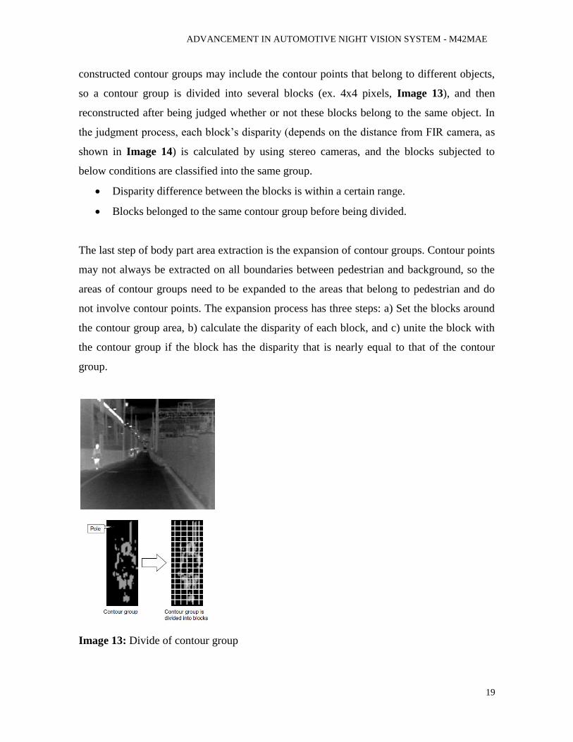
constructed contour groups may include the contour points that belong to different objects,
so a contour group is divided into several blocks (ex. 4x4 pixels, Image 13), and then
reconstructed after being judged whether or not these blocks belong to the same object. In
the judgment process, each block’s disparity (depends on the distance from FIR camera, as
shown in Image 14) is calculated by using stereo cameras, and the blocks subjected to
below conditions are classified into the same group.
Disparity difference between the blocks is within a certain range.
Blocks belonged to the same contour group before being divided.
The last step of body part area extraction is the expansion of contour groups. Contour points
may not always be extracted on all boundaries between pedestrian and background, so the
areas of contour groups need to be expanded to the areas that belong to pedestrian and do
not involve contour points. The expansion process has three steps: a) Set the blocks around
the contour group area, b) calculate the disparity of each block, and c) unite the block with
the contour group if the block has the disparity that is nearly equal to that of the contour
group.
Image 13: Divide of contour group
ADVANCEMENT IN AUTOMOTIVE NIGHT VISION SYSTEM - M42MAE
20
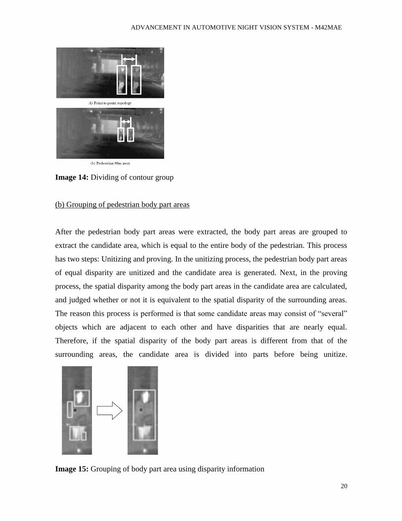
Image 14: Dividing of contour group
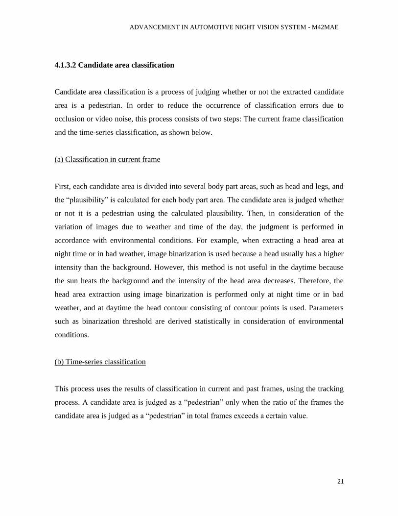
(b) Grouping of pedestrian body part areas
After the pedestrian body part areas were extracted, the body part areas are grouped to
extract the candidate area, which is equal to the entire body of the pedestrian. This process
has two steps: Unitizing and proving. In the unitizing process, the pedestrian body part areas
of equal disparity are unitized and the candidate area is generated. Next, in the proving
process, the spatial disparity among the body part areas in the candidate area are calculated,
and judged whether or not it is equivalent to the spatial disparity of the surrounding areas.
The reason this process is performed is that some candidate areas may consist of “several”
objects which are adjacent to each other and have disparities that are nearly equal.
Therefore, if the spatial disparity of the body part areas is different from that of the
surrounding areas, the candidate area is divided into parts before being unitize.
Image 15: Grouping of body part area using disparity information
ADVANCEMENT IN AUTOMOTIVE NIGHT VISION SYSTEM - M42MAE
21
4.1.3.2 Candidate area classification
Candidate area classification is a process of judging whether or not the extracted candidate
area is a pedestrian. In order to reduce the occurrence of classification errors due to
occlusion or video noise, this process consists of two steps: The current frame classification
and the time-series classification, as shown below.
(a) Classification in current frame
First, each candidate area is divided into several body part areas, such as head and legs, and
the “plausibility” is calculated for each body part area. The candidate area is judged whether
or not it is a pedestrian using the calculated plausibility. Then, in consideration of the
variation of images due to weather and time of the day, the judgment is performed in
accordance with environmental conditions. For example, when extracting a head area at
night time or in bad weather, image binarization is used because a head usually has a higher
intensity than the background. However, this method is not useful in the daytime because
the sun heats the background and the intensity of the head area decreases. Therefore, the
head area extraction using image binarization is performed only at night time or in bad
weather, and at daytime the head contour consisting of contour points is used. Parameters
such as binarization threshold are derived statistically in consideration of environmental
conditions.
(b) Time-series classification
This process uses the results of classification in current and past frames, using the tracking
process. A candidate area is judged as a “pedestrian” only when the ratio of the frames the
candidate area is judged as a “pedestrian” in total frames exceeds a certain value.
ADVANCEMENT IN AUTOMOTIVE NIGHT VISION SYSTEM - M42MAE
22
4.1.3.3 Candidate area tracking
Candidate areas are tracked over time so that candidate area classification can be performed.
In the candidate area tracking process, the similarity between the candidate areas in the
current and last frames is calculated. If the similarity is larger than a certain level, then these
candidate areas are labelled as the same. In calculating the similarity, parameters such as
candidate area size variation and gravity difference are used. In addition, when the
difference of gravity is calculated, the coordinates of the candidate area are corrected by
calculating the yaw and pitch angles of the car.
4.2 INTELLIGENT VISION FOR AUTOMOBILES AT NIGHT (IVAN)
Car driving is a process of which the safety heavily relies on drivers’ accurate visual
information processing and proper reactions. Objects such as road signs, warnings and
lane lines are critical for aiding drivers to understand the road conditions. Failures in
recognizing these objects may cause serious consequences. Practically, drivers may
experience more difficulties in identifying these objects during the night driving, leading
to a much higher probability of traffic accident. Statistics shows that, more than 20% of
fatal traffic accidents occurred between midnight and 6:00 in the morning, which accounts
for only 2.4% of total traffic volume. Besides the drivers’ lacking of attention, largely
reduced visual acuity and field of vision at night due to low illumination caused by factors
such bad weathers, obscure street lamps and limited range of headlights is also a major
reason for this situation. For example, dipped headlights only illuminate about 56 meters
when the breaking distance at 100 km/h is about 80 meters.
Facing this problem, attentions have been attracted to the research of automobile night
vision systems which help to improve the visibility of objects on the road at night. In
general, such a system is equipped with night visors such as infrared cameras from
which the information of objects presenting on the road, such as bends, poles, pedestrians,
other cars etc. can be extracted.
Then, this system will inform drivers by means of visual, acoustic or other signals about
the obstacles appearing in their way. Some of the research results have been transformed
ADVANCEMENT IN AUTOMOTIVE NIGHT VISION SYSTEM - M42MAE
23
into real products installed on high-end automobiles such as BMW 6 Series Coupe and
Mercedes-Benz 2007 S-Class series.
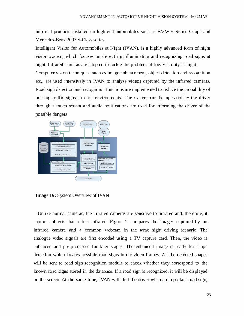
Intelligent Vision for Automobiles at Night (IVAN), is a highly advanced form of night
vision system, which focuses on detecting, illuminating and recognizing road signs at
night. Infrared cameras are adopted to tackle the problem of low visibility at night.
Computer vision techniques, such as image enhancement, object detection and recognition
etc., are used intensively in IVAN to analyse videos captured by the infrared cameras.
Road sign detection and recognition functions are implemented to reduce the probability of
missing traffic signs in dark environments. The system can be operated by the driver
through a touch screen and audio notifications are used for informing the driver of the
possible dangers.
Image 16: System Overview of IVAN
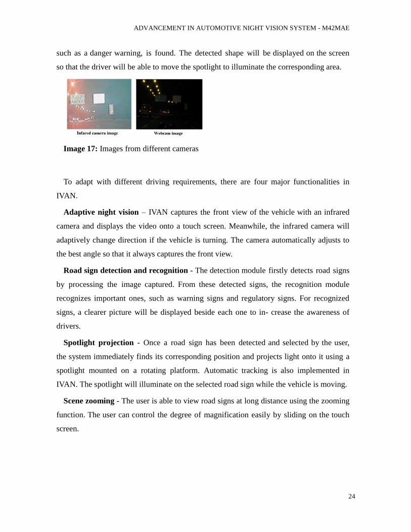
Unlike normal cameras, the infrared cameras are sensitive to infrared and, therefore, it
captures objects that reflect infrared. Figure 2 compares the images captured by an
infrared camera and a common webcam in the same night driving scenario. The
analogue video signals are first encoded using a TV capture card. Then, the video is
enhanced and pre-processed for later stages. The enhanced image is ready for shape
detection which locates possible road signs in the video frames. All the detected shapes
will be sent to road sign recognition module to check whether they correspond to the
known road signs stored in the database. If a road sign is recognized, it will be displayed
on the screen. At the same time, IVAN will alert the driver when an important road sign,
ADVANCEMENT IN AUTOMOTIVE NIGHT VISION SYSTEM - M42MAE
24
such as a danger warning, is found. The detected shape will be displayed on the screen
so that the driver will be able to move the spotlight to illuminate the corresponding area.
Image 17: Images from different cameras
To adapt with different driving requirements, there are four major functionalities in
IVAN.
Adaptive night vision – IVAN captures the front view of the vehicle with an infrared
camera and displays the video onto a touch screen. Meanwhile, the infrared camera will
adaptively change direction if the vehicle is turning. The camera automatically adjusts to
the best angle so that it always captures the front view.
Road sign detection and recognition - The detection module firstly detects road signs
by processing the image captured. From these detected signs, the recognition module
recognizes important ones, such as warning signs and regulatory signs. For recognized
signs, a clearer picture will be displayed beside each one to in- crease the awareness of
drivers.
Spotlight projection - Once a road sign has been detected and selected by the user,
the system immediately finds its corresponding position and projects light onto it using a
spotlight mounted on a rotating platform. Automatic tracking is also implemented in
IVAN. The spotlight will illuminate on the selected road sign while the vehicle is moving.
Scene zooming - The user is able to view road signs at long distance using the zooming
function. The user can control the degree of magnification easily by sliding on the touch
screen.
ADVANCEMENT IN AUTOMOTIVE NIGHT VISION SYSTEM - M42MAE
25
4.2.1 WORKING OF IVAN
The road sign detection module locates and segments potential road signs in real-time.
Based on the observation that most of the road signs are in regular geometric shapes, such
as rectangle, triangle and circle, the following steps are used for road sign detection in
IVAN. The input image is first processed to reduce the noise by using a 5x5 Gaussian filter.
Shades of grey are then converted to black and white (binarization) using different
thresholds. For each segmented image thus obtained, contours of the white regions are
extracted. The contours are approximated into polygons by using Douglas-Peucker
algorithm, which recursively find out a subset of vertices that the shape enclosed is similar
to the original one. The resultant polygons approximated are further analysed: In order to
improve detection speed and accuracy, they are classified into “quadrilaterals” and
“triangles” by polygons' vertex number. Their interior angles are then calculated.
Candidate road signs are selected from the detected shape by checking their interior
angles. For quadrilaterals, the interior angles should be within the range 90 degrees; for
triangles, the interior angles should be within the range 60 degrees. The parameters are
constants which are defined to offer tolerances to deal with the perspective distortion
and noises in the frame captured. Shapes will be discarded if they do not have three/four
vertices respectively or their interior angles violate the rules defined above. Consequently,
a set of quadrilaterals and triangles are detected, these shapes are regarded as traffic signs
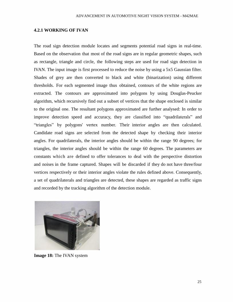
and recorded by the tracking algorithm of the detection module.
Image 18: The IVAN system
ADVANCEMENT IN AUTOMOTIVE NIGHT VISION SYSTEM - M42MAE
26
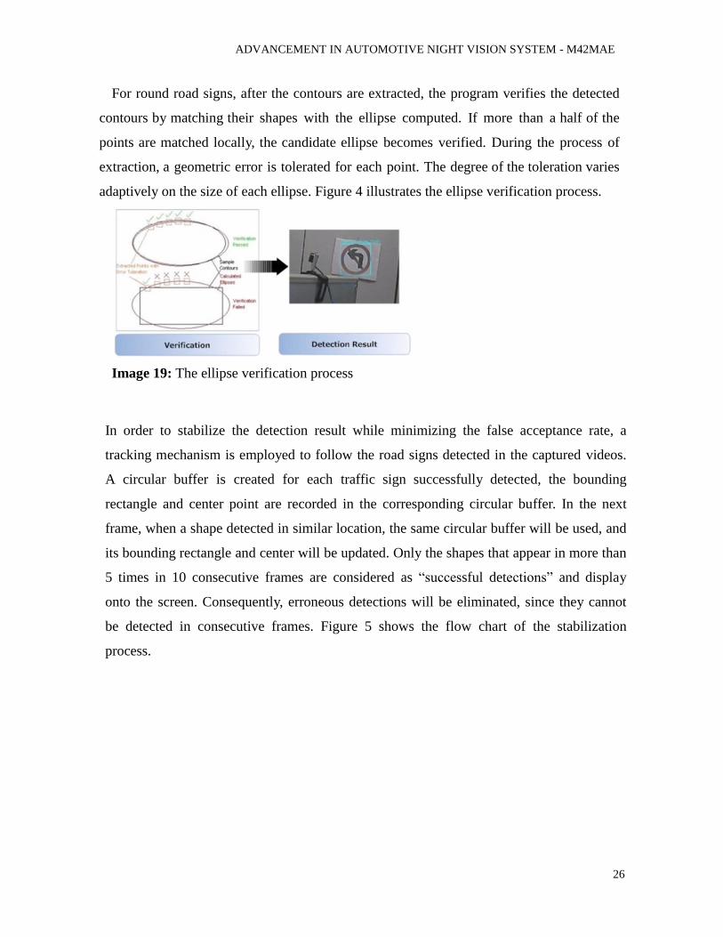
For round road signs, after the contours are extracted, the program verifies the detected
contours by matching their shapes with the ellipse computed. If more than a half of the
points are matched locally, the candidate ellipse becomes verified. During the process of
extraction, a geometric error is tolerated for each point. The degree of the toleration varies
adaptively on the size of each ellipse. Figure 4 illustrates the ellipse verification process.
Image 19: The ellipse verification process
In order to stabilize the detection result while minimizing the false acceptance rate, a
tracking mechanism is employed to follow the road signs detected in the captured videos.
A circular buffer is created for each traffic sign successfully detected, the bounding
rectangle and center point are recorded in the corresponding circular buffer. In the next
frame, when a shape detected in similar location, the same circular buffer will be used, and
its bounding rectangle and center will be updated. Only the shapes that appear in more than
5 times in 10 consecutive frames are considered as “successful detections” and display
onto the screen. Consequently, erroneous detections will be eliminated, since they cannot
be detected in consecutive frames. Figure 5 shows the flow chart of the stabilization
process.
ADVANCEMENT IN AUTOMOTIVE NIGHT VISION SYSTEM - M42MAE
27
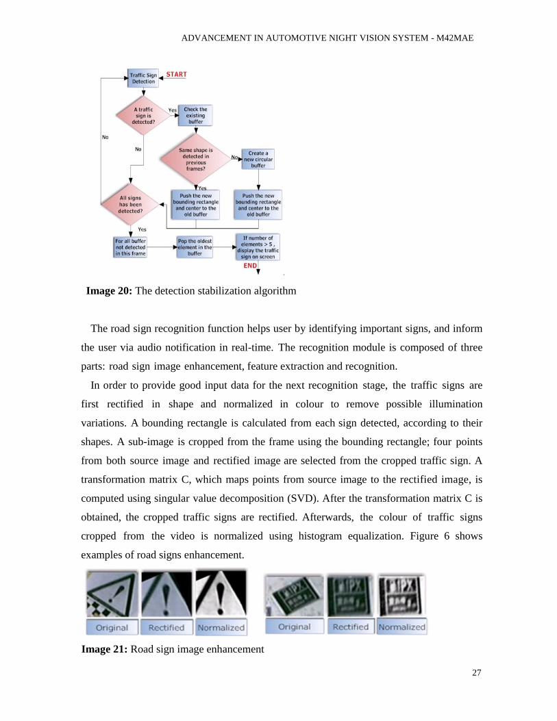
Image 20: The detection stabilization algorithm
The road sign recognition function helps user by identifying important signs, and inform
the user via audio notification in real-time. The recognition module is composed of three
parts: road sign image enhancement, feature extraction and recognition.
In order to provide good input data for the next recognition stage, the traffic signs are
first rectified in shape and normalized in colour to remove possible illumination
variations. A bounding rectangle is calculated from each sign detected, according to their
shapes. A sub-image is cropped from the frame using the bounding rectangle; four points
from both source image and rectified image are selected from the cropped traffic sign. A
transformation matrix C, which maps points from source image to the rectified image, is
computed using singular value decomposition (SVD). After the transformation matrix C is
obtained, the cropped traffic signs are rectified. Afterwards, the colour of traffic signs
cropped from the video is normalized using histogram equalization. Figure 6 shows
examples of road signs enhancement.
Image 21: Road sign image enhancement
ADVANCEMENT IN AUTOMOTIVE NIGHT VISION SYSTEM - M42MAE
28
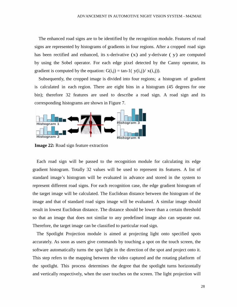
The enhanced road signs are to be identified by the recognition module. Features of road
signs are represented by histograms of gradients in four regions. After a cropped road sign
has been rectified and enhanced, its x-derivative (x) and y-derivate ( y) are computed
by using the Sobel operator. For each edge pixel detected by the Canny operator, its
gradient is computed by the equation: G(i,j) = tan-1( y(i,j)/ x(i,j)).
Subsequently, the cropped image is divided into four regions; a histogram of gradient
is calculated in each region. There are eight bins in a histogram (45 degrees for one
bin); therefore 32 features are used to describe a road sign. A road sign and its
corresponding histograms are shown in Figure 7.
Image 22: Road sign feature extraction
Each road sign will be passed to the recognition module for calculating its edge
gradient histogram. Totally 32 values will be used to represent its features. A list of
standard image’s histogram will be evaluated in advance and stored in the system to
represent different road signs. For each recognition case, the edge gradient histogram of
the target image will be calculated. The Euclidean distance between the histogram of the
image and that of standard road signs image will be evaluated. A similar image should
result in lowest Euclidean distance. The distance should be lower than a certain threshold
so that an image that does not similar to any predefined image also can separate out.
Therefore, the target image can be classified to particular road sign.
The Spotlight Projection module is aimed at projecting light onto specified spots
accurately. As soon as users give commands by touching a spot on the touch screen, the
software automatically turns the spot light in the direction of the spot and project onto it.
This step refers to the mapping between the video captured and the rotating platform of
the spotlight. This process determines the degree that the spotlight turns horizontally
and vertically respectively, when the user touches on the screen. The light projection will

ADVANCEMENT IN AUTOMOTIVE NIGHT VISION SYSTEM - M42MAE
29
last for one second and the spot will track the detected road sign within this time interval.
Hence, the calculation process needs to continuously generate control signals in real-
time. The projection will terminate if the specified spot moves out of the image or a new
command is given. Meanwhile, to ensure that the light will not glare drivers in the
opposite direction, tracking instruction is not allowed if the angle of elevation for the
spotlight is too low.
Image 23: Adaptive infrared camera
The night vision feature is implemented by utilizing an infrared camera to capture the
front view. Since infrared camera has strong sensibility against infrared, the captured
images enable drivers to see the road conditions and identify road signs or other objects at
night. Inspired by BMW 7 Series’ Adaptive Headlights System, an adaptive control
mechanism is implemented by estimating an adjustment angle from the vehicle’s speed
and turning angles. Figure 8 illustrates the usage of camera adjustment.
Image 24: Sample cases of road sign detection
ADVANCEMENT IN AUTOMOTIVE NIGHT VISION SYSTEM - M42MAE
30
4.3. TRUE-COLOUR NIGHT VISION
Numerous studies have shown that scene understanding, reaction time, and object
identification is faster and more accurate with colour imagery than with monochrome
imagery. Considering surveillance, reconnaissance, and security applications, colour
imagery has two main benefits over monochrome imagery. The first is that colour improves
contrast, which allows for better scene segmentation and object detection. This contrast
improvement can apply to both true-colour and false-colour images, where false-colour
imagery can be formed by the fusion of images from cameras with different spectral
sensitivity (e.g., image intensified with thermal IR). The second benefit of colour is that it
provides more information. Access to stored colour knowledge in the brain or a computer
database can be utilized to enable better object identification and scene understanding. This
second improvement applies primarily to true-colour images, since false-colour images do
not necessarily match the stored colour information, and may in fact be detrimental in this
regard.
General benefits and drawbacks of true-colour night vision (TCNV) systems are listed in
Table 1, and examples of the utility of true-colour information are shown in Figure 1. For
example, Figure 1 demonstrates that successfully finding the man with the orange shirt,
determining the difference between flags, or being able to pick out the blue car are all tasks
that benefit greatly from the additional information that true-colour imagery provides.
To obtain true-colour images a camera must be sensitive to the visible portion of the
electromagnetic spectrum and there must be a mechanism to filter or split the different parts
(i.e., colours) of the visible spectrum so that colour information can be extracted. This need
to filter the input has the consequence of reducing the available signal to a detector, which
is the primary drawback of a true-colour system intended for use in low-light situations.
Furthermore, standard monochrome image-intensified systems are typically designed to
take advantage of the relatively high near-infrared (NIR) signal available from the night
sky. To mitigate the inherent reduction in signal due to filtering, a true-colour system should
ADVANCEMENT IN AUTOMOTIVE NIGHT VISION SYSTEM - M42MAE
31
also be able to utilize this NIR light. In addition, sensitivity to NIR is also needed for
viewing of IR laser aiming devices, as demonstrated in Figure 2. The ability to produce
true-colour content, while maintaining sensitivity to NIR is one of the inherent challenges in
making a viable true-colour night vision camera.
New camera technology and image processing routines have been developed to enable the
use of true-colour information from the visible portion of the spectrum while utilizing the
full visible to near infrared (V-NIR) range (roughly 400 to 1000 nm in wavelength) for the
brightness information. Two different types of TCNV cameras are there; one camera uses a
liquid crystal filter in front of an image intensified detector and the other uses a mosaic filter
deposited on the pixels of an EMCCD detector. Both cameras are based on new
technologies: the liquid crystal camera uses fast switching filters with optimized
transmission bands, and the mosaic filter camera relies on recent advances in CCD
technology
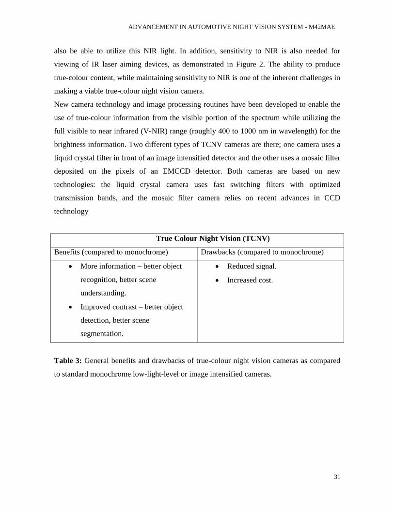
True Colour Night Vision (TCNV)
Benefits (compared to monochrome) Drawbacks (compared to monochrome)
More information – better object
recognition, better scene
understanding.
Improved contrast – better object
detection, better scene
segmentation.
Reduced signal.
Increased cost.
Table 3: General benefits and drawbacks of true-colour night vision cameras as compared
to standard monochrome low-light-level or image intensified cameras.
ADVANCEMENT IN AUTOMOTIVE NIGHT VISION SYSTEM - M42MAE
32
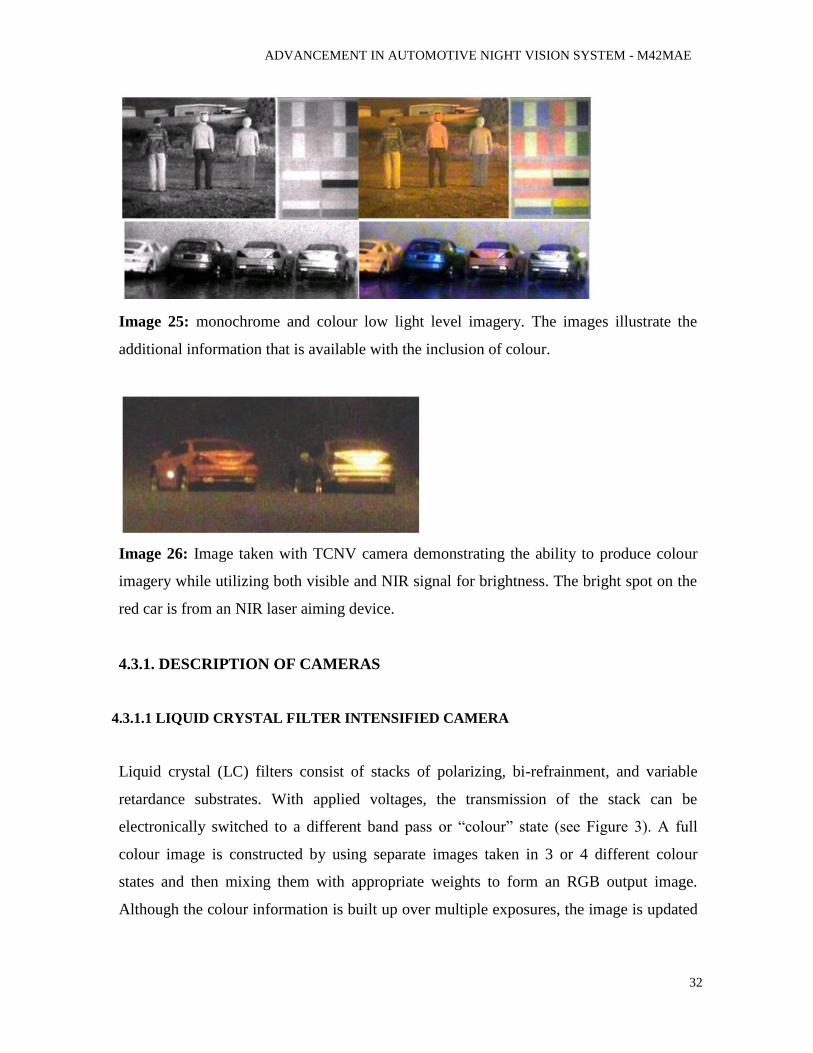
Image 25: monochrome and colour low light level imagery. The images illustrate the
additional information that is available with the inclusion of colour.
Image 26: Image taken with TCNV camera demonstrating the ability to produce colour
imagery while utilizing both visible and NIR signal for brightness. The bright spot on the
red car is from an NIR laser aiming device.
4.3.1. DESCRIPTION OF CAMERAS
4.3.1.1 LIQUID CRYSTAL FILTER INTENSIFIED CAMERA
Liquid crystal (LC) filters consist of stacks of polarizing, bi-refrainment, and variable
retardance substrates. With applied voltages, the transmission of the stack can be
electronically switched to a different band pass or “colour” state (see Figure 3). A full
colour image is constructed by using separate images taken in 3 or 4 different colour
states and then mixing them with appropriate weights to form an RGB output image.
Although the colour information is built up over multiple exposures, the image is updated
ADVANCEMENT IN AUTOMOTIVE NIGHT VISION SYSTEM - M42MAE
33
with each captured frame, rather than waiting until a complete set of 3 or 4 frames is
captured.
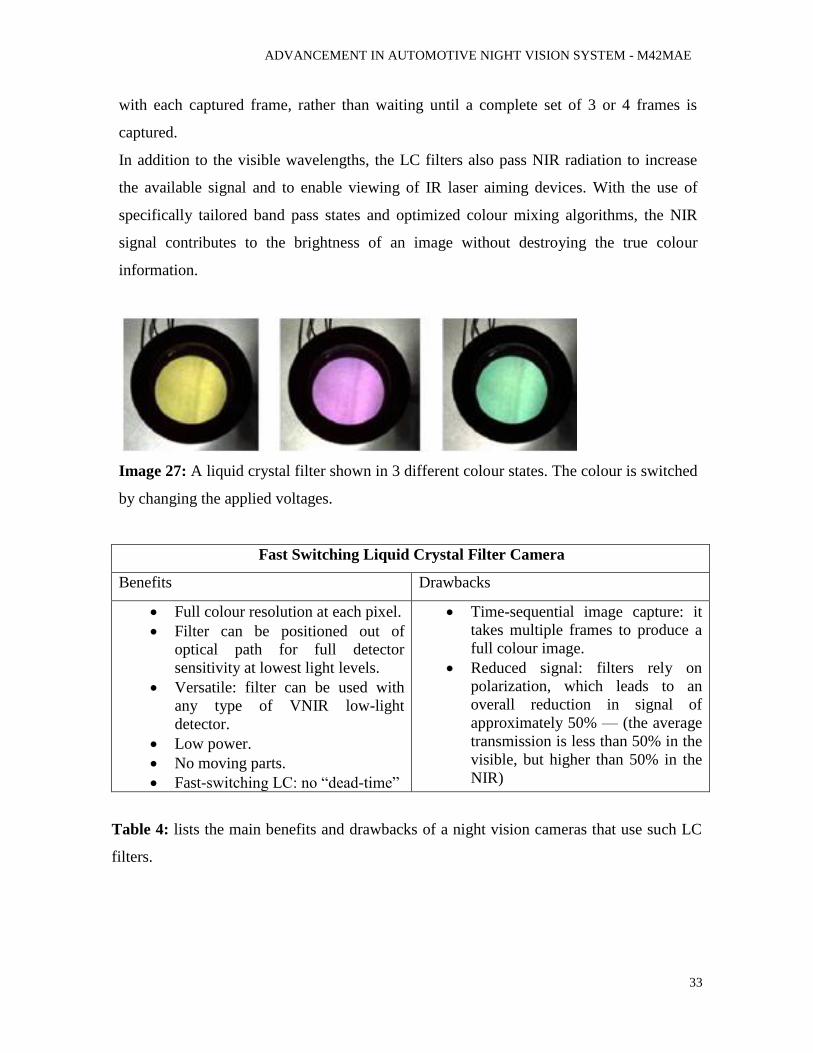
In addition to the visible wavelengths, the LC filters also pass NIR radiation to increase
the available signal and to enable viewing of IR laser aiming devices. With the use of
specifically tailored band pass states and optimized colour mixing algorithms, the NIR
signal contributes to the brightness of an image without destroying the true colour
information.
Image 27: A liquid crystal filter shown in 3 different colour states. The colour is switched
by changing the applied voltages.
Fast Switching Liquid Crystal Filter Camera
Benefits Drawbacks
Full colour resolution at each pixel.
Filter can be positioned out of
optical path for full detector
sensitivity at lowest light levels.
Versatile: filter can be used with
any type of VNIR low-light
detector.
Low power.
No moving parts.
Fast-switching LC: no “dead-time”
Time-sequential image capture: it
takes multiple frames to produce a
full colour image.
Reduced signal: filters rely on
polarization, which leads to an
overall reduction in signal of
approximately 50% — (the average
transmission is less than 50% in the
visible, but higher than 50% in the
NIR)
Table 4: lists the main benefits and drawbacks of a night vision cameras that use such LC
filters.
ADVANCEMENT IN AUTOMOTIVE NIGHT VISION SYSTEM - M42MAE
34
The latest LC filters are extremely fast switching taking less than 1ms to switch between
any two states. Fast switching enables the camera to operate without “dead-time” and the
associated light loss while the filter is in an undefined state. With typical LC filters it is
impractical to operate at video rates, i.e., 30 frames/second (fps), since the dead-time is on
the same order as the frame period. However, with the fast-switching filter, rates as high as
180 fps are routinely used.
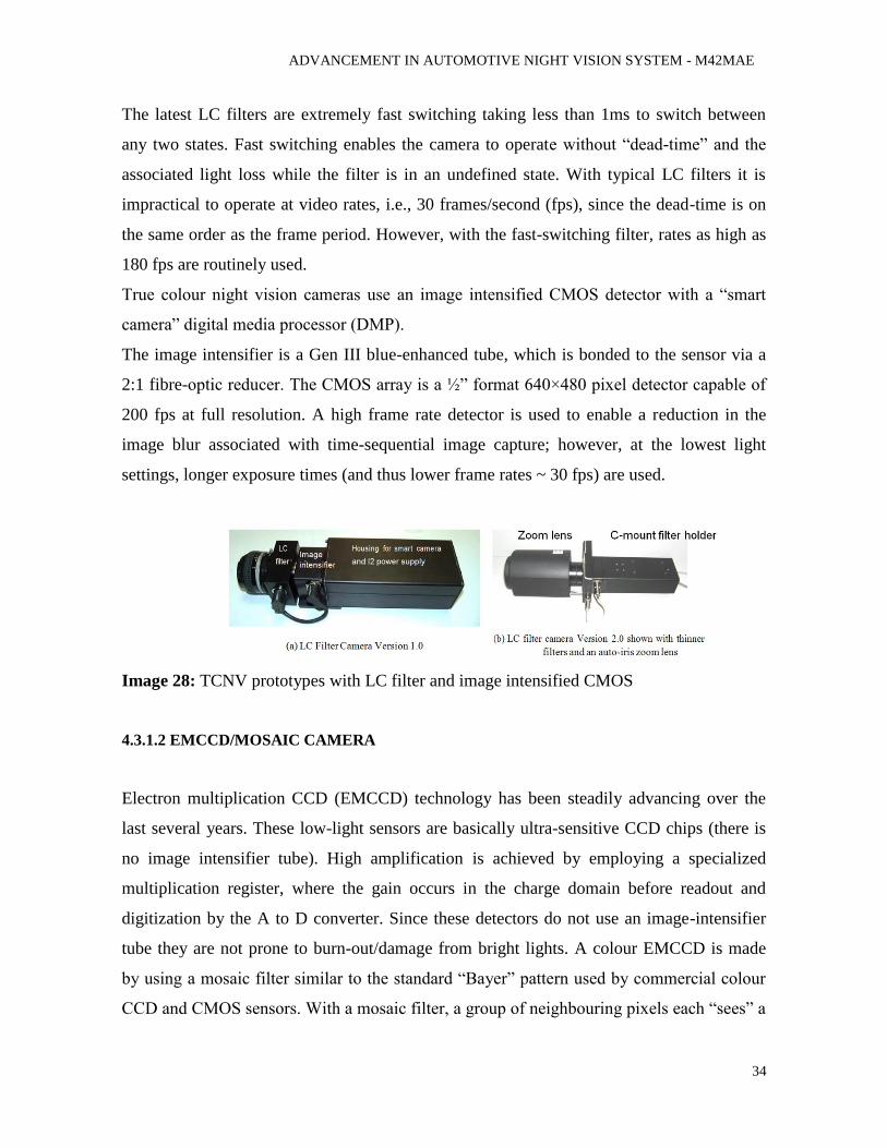
True colour night vision cameras use an image intensified CMOS detector with a “smart
camera” digital media processor (DMP).
The image intensifier is a Gen III blue-enhanced tube, which is bonded to the sensor via a
2:1 fibre-optic reducer. The CMOS array is a ½” format 640×480 pixel detector capable of
200 fps at full resolution. A high frame rate detector is used to enable a reduction in the
image blur associated with time-sequential image capture; however, at the lowest light
settings, longer exposure times (and thus lower frame rates ~ 30 fps) are used.
Image 28: TCNV prototypes with LC filter and image intensified CMOS
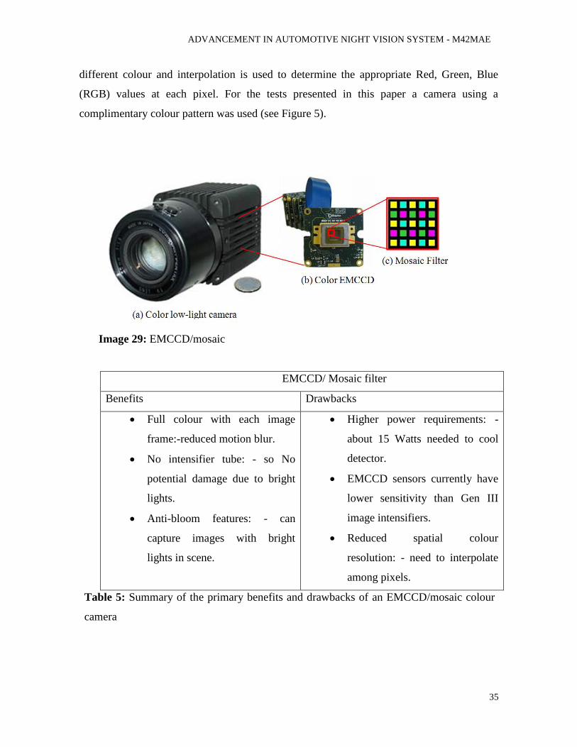
4.3.1.2 EMCCD/MOSAIC CAMERA
Electron multiplication CCD (EMCCD) technology has been steadily advancing over the
last several years. These low-light sensors are basically ultra-sensitive CCD chips (there is
no image intensifier tube). High amplification is achieved by employing a specialized
multiplication register, where the gain occurs in the charge domain before readout and
digitization by the A to D converter. Since these detectors do not use an image-intensifier
tube they are not prone to burn-out/damage from bright lights. A colour EMCCD is made
by using a mosaic filter similar to the standard “Bayer” pattern used by commercial colour
CCD and CMOS sensors. With a mosaic filter, a group of neighbouring pixels each “sees” a
ADVANCEMENT IN AUTOMOTIVE NIGHT VISION SYSTEM - M42MAE
35
different colour and interpolation is used to determine the appropriate Red, Green, Blue
(RGB) values at each pixel. For the tests presented in this paper a camera using a
complimentary colour pattern was used (see Figure 5).
Image 29: EMCCD/mosaic
EMCCD/ Mosaic filter
Benefits Drawbacks
Full colour with each image
frame:-reduced motion blur.
No intensifier tube: - so No
potential damage due to bright
lights.
Anti-bloom features: - can
capture images with bright
lights in scene.
Higher power requirements: -
about 15 Watts needed to cool
detector.
EMCCD sensors currently have
lower sensitivity than Gen III
image intensifiers.
Reduced spatial colour
resolution: - need to interpolate
among pixels.
Table 5: Summary of the primary benefits and drawbacks of an EMCCD/mosaic colour
camera
ADVANCEMENT IN AUTOMOTIVE NIGHT VISION SYSTEM - M42MAE
36
A summary of the major benefits and drawback of an EMCCD/mosaic camera are listed
in Table 3. Most of the benefits are related to the fact that an intensifier tube is not used;
however, there are three main drawbacks to this scheme: (1) the sensitivity currently does
not match that achieved by a Gen III image intensifier tube, (2) cooling is needed to
reduce the dark current on the chip, which equates to higher power consumption; and (3)
interpolation is needed to construct (“de-mosaic”) an image, resulting in reduced colour
resolution.
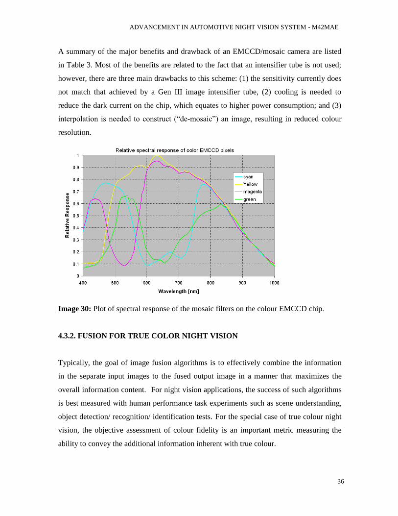
Image 30: Plot of spectral response of the mosaic filters on the colour EMCCD chip.
4.3.2. FUSION FOR TRUE COLOR NIGHT VISION
Typically, the goal of image fusion algorithms is to effectively combine the information
in the separate input images to the fused output image in a manner that maximizes the
overall information content. For night vision applications, the success of such algorithms
is best measured with human performance task experiments such as scene understanding,
object detection/ recognition/ identification tests. For the special case of true colour night
vision, the objective assessment of colour fidelity is an important metric measuring the
ability to convey the additional information inherent with true colour.
ADVANCEMENT IN AUTOMOTIVE NIGHT VISION SYSTEM - M42MAE
37
To render appropriate colour fusion output it is beneficial to separate the colour values
(i.e., chroma) from the brightness values (i.e., luma) using a colour space such as La*b*
or YUV instead of the Red Green and Blue (RGB) colour space. For the present system
the chroma values are obtained directly from the colour EMCCD camera, using several
proprietary algorithms to improve the colour content, and the luma values are determined
using an algorithm that fuses the brightness of the two cameras.
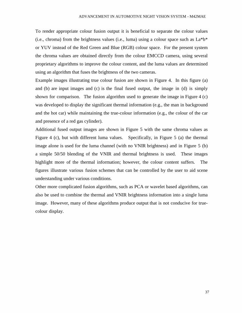
Example images illustrating true colour fusion are shown in Figure 4. In this figure (a)
and (b) are input images and (c) is the final fused output, the image in (d) is simply
shown for comparison. The fusion algorithm used to generate the image in Figure 4 (c)
was developed to display the significant thermal information (e.g., the man in background
and the hot car) while maintaining the true-colour information (e.g., the colour of the car
and presence of a red gas cylinder).
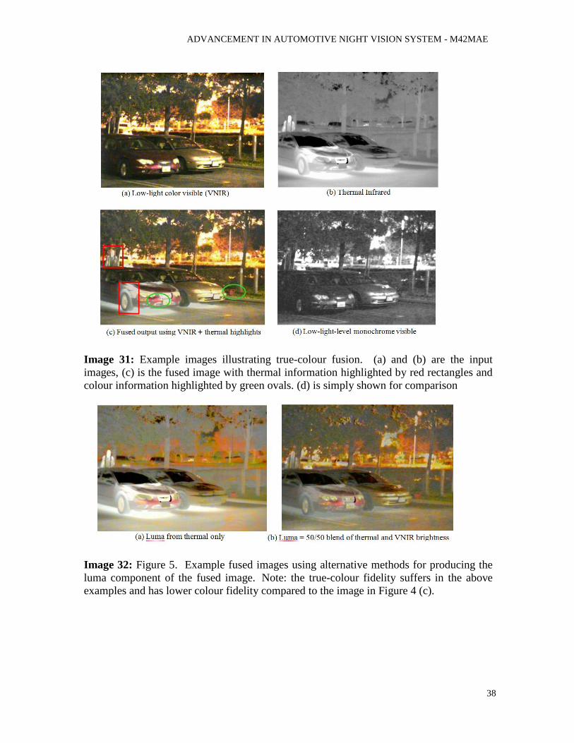
Additional fused output images are shown in Figure 5 with the same chroma values as
Figure 4 (c), but with different luma values. Specifically, in Figure 5 (a) the thermal
image alone is used for the luma channel (with no VNIR brightness) and in Figure 5 (b)
a simple 50/50 blending of the VNIR and thermal brightness is used. These images
highlight more of the thermal information; however, the colour content suffers. The
figures illustrate various fusion schemes that can be controlled by the user to aid scene
understanding under various conditions.
Other more complicated fusion algorithms, such as PCA or wavelet based algorithms, can
also be used to combine the thermal and VNIR brightness information into a single luma
image. However, many of these algorithms produce output that is not conducive for true-
colour display.
ADVANCEMENT IN AUTOMOTIVE NIGHT VISION SYSTEM - M42MAE
38
Image 31: Example images illustrating true-colour fusion. (a) and (b) are the input
images, (c) is the fused image with thermal information highlighted by red rectangles and
colour information highlighted by green ovals. (d) is simply shown for comparison
Image 32: Figure 5. Example fused images using alternative methods for producing the
luma component of the fused image. Note: the true-colour fidelity suffers in the above
examples and has lower colour fidelity compared to the image in Figure 4 (c).
ADVANCEMENT IN AUTOMOTIVE NIGHT VISION SYSTEM - M42MAE
39
5. DISCUSSION
The scope of this study is to combine the present technologies available in night vision
system such as pedestrian detection, intelligent vision of automobiles during night (IVAN)
and True Colour Night Vision and to display this information from the night vision system
directly to the windscreen rather than to a small centre console display. Head up display is
one of the prominent and simple techniques which are used for windscreen display.
Head up display consists of small display unit that generates the image which is being
reflected on the windscreen using a partial reflecting film. In present HUD no image is
projected on the screen. Instead of projection technology, the image formed on the display
is reflected to generate an image on the windscreen. But this kind of windscreen has its own
draw backs. It cannot be prominently visible during day time and also can't be projected on
a wider area of windscreen as the image is formed in a small display unit which is being
reflected.
The data provided by the IVAN and the pedestrian detection system when combined with
vehicle navigations and other information, it gets congested and confusing for the driver
when displayed on small screen. IVAN and pedestrian detection system is used only during
night time, so it is well suited for windscreen projection since there is no background with
high intensity lights. Hence, the use of projection technology is been adopted to use the
windscreen itself as a projecting screen.
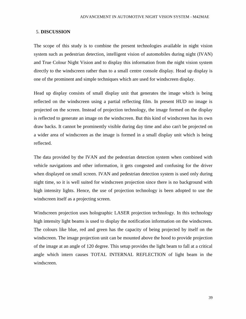
Windscreen projection uses holographic LASER projection technology. In this technology
high intensity light beams is used to display the notification information on the windscreen.
The colours like blue, red and green has the capacity of being projected by itself on the
windscreen. The image projection unit can be mounted above the hood to provide projection
of the image at an angle of 120 degree. This setup provides the light beam to fall at a critical
angle which intern causes TOTAL INTERNAL REFLECTION of light beam in the
windscreen.
ADVANCEMENT IN AUTOMOTIVE NIGHT VISION SYSTEM - M42MAE
40
Image 33: Figure showing different parts of projecting units.
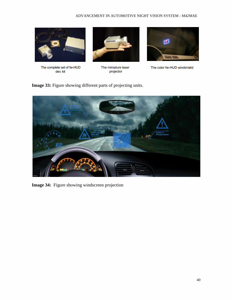
Image 34: Figure showing windscreen projection
ADVANCEMENT IN AUTOMOTIVE NIGHT VISION SYSTEM - M42MAE
41
6. CONCLUSION
Automotive Head up display is an emerging technology which has many advantages on
the ergonomic aspects as well as for the comfort of driver. Researches are going on for the
development of HUD to minimise the space of the central console and displaying all the
necessary information in the windshield itself. But HUD has some limitations, that for
HUD, it requires a partial reflecting element to reflect the projected image in the
windscreen to act as a screen, also the projector must be arranged with projection angle
above the critical angle of the glass to reflect it image. Another, one main problem is that
HUD cannot provide a better display during the day time. The background light is so high
that the projected image won't be properly seen. This become challenging and limits the
display area of HUD to a small portion of the windshield.
But, HUD is more preferable for the night drive. During night, except the high beam of
approaching vehicles, high intensity lights are lesser. So HUD can work well for the night
vision. Presently, in night vision technology, after spotting a human or animal in the field
of driving, the information is displayed on the small screen on the central consol. This is
ergonomically, not completely satisfactory for the drive, as he need to take away his eyes
from the road to have a look at the screen. So, mostly drivers won't relay on the night
vision all the time.
With the use of holographic glass projection technology the vision system can be
developed to a next generation, with the combination of IVAN technology and pedestrian
detection with holographic projection the exact position, size and type of the object
detected can be show directly on the windshield glass were the driver see through. The
high intensity holographic laser projection can display the symbols detected by the IVAN
as well as the road markings on the wind screen. Also by using this projection the
boundary box of the human or animal can be shown in the wind screen at the right
position of the object which the driver could see through the windscreen.
ADVANCEMENT IN AUTOMOTIVE NIGHT VISION SYSTEM - M42MAE
42
RECOMENDATION
With this study we have identified the flaws in present night vision system. We are
providing supporting documents that can improve the present intelligent night vision
system with true colour output and windscreen projection which can be considered for the
future development and research in ITS. If this system comes into existence the use of
night beam head lights can be avoided to a greater extent.
ADVANCEMENT IN AUTOMOTIVE NIGHT VISION SYSTEM - M42MAE
43
REFERENCES
1. K. Rumar, Adaptive illumination systems for motor vehicles: Towards a more
intelligent headlighting system, Report no.UMTRI-97-7. Ann Arbor, MI: The
University of Michigan Transport Research Institute, 1997.
2. P.A. Thompson, Daytime running lamps (DRLs) for pedestrian protection ,
Proceedings of Progress in automotive lighting, Darmstadt, Gerrmany, 2003.
3. H. Nanda and L. Davis, “Probabilistic Template Based Pedestrian Detection in Infrared
Videos,” in Procs. IEEE Intelligent Vehicles Symposium 2002, June 2002.
4. Procs. IEEE Intelligent Vehicles Symposium 2002, June 2002.
5. Y. L. Guilloux and J. Lonnoy, “PAROTO Project: The Benefit of Infrared Imagery for
Ob-stacle Avoidance,” in Procs. IEEE Intelligent Vehicles Symposium 2002, June
2002.
6. B. Heisele and C. Wohler,¨ “Motion-based Recognition of Pedestrians,” in Procs. IEEE
Intl. Conf. on Pattern Recognition, pp. 1325–1330, June 1998.
7. R. Cutler and L. S. Davis, “Robust real-time periodic motion detection, analysis and
appli-cations,” IEEE Trans. on PAMI, vol. 22, pp. 781–796, Aug. 2000.
8. M. Bertozzi, A. Broggi, T. Graf, P. Grisleri, and M. Meinecke, “Pedestrian Detection in
Infrared Images,” in Procs. IEEE Intelligent Vehicles Symposium 2003, June 2003. in
press.
9. Angle, H., Ste-Croix, C., and Kittel, E., “Review of Fusion Systems and
Contributing Technologies for SIHS,”
10. available from http://handle.dtic.mil/100.2/ADA482098. 11. Cavanillas, J.A.A., "The Role of Color and False Color in Object Recognition with
Degraded and Non-Degraded 12. Images," Thesis, Naval Postgraduate School Monterey, CA (Sep. 1999). 13. Sampson, M.T., "An Assessment of the Impact of Fused Monochrome and Fused
Color Night Vision Displays on 14. Reaction Time and Accuracy in Target Detection," Thesis, Naval Postgraduate School
Monterey, CA (Sep. 1996).
15. Fay, D.A., et. al., "Fusion of Multi-Sensor Imagery for Night Vision: Color
Visualization, Target Learning and 16. Search," Proc. of FUSION 2000, Vol.1, pp. 303-310, 2000 17. Hogervorst, M.A. and Toet, A., "Method for applying daytime colors to nighttime
imagery in realtime," Proc of 18. SPIE Vol. 6974, 697403-1 (2008).
19. D. Douglas, T. Peucker, "Algorithms for the reduction of the number of
points required to represent a digitized line or its caricature", The Canadian
Cartographer 10(2), 112-122,
20. 1973.
21. B., David, N. Trefethen, Numerical linear algebra, Phila- delphia: Society for
Industrial and Applied Mathematics, 22. 1997 23. R.C. Gonzalez, R.E. Woods, Digital Image Processing, Prentice Hall, 2002
ADVANCEMENT IN AUTOMOTIVE NIGHT VISION SYSTEM - M42MAE
44
BIBLIOGRAPHY
http://www.pspc.dibe.unige.it/~drivsco
http://www.bmw.com/com/en/newvehicles/6series/coupe/2007/allfacts/ergonomics_nightv
ision.html
http://www.mercedesforum.com/m_35841/tm.htm
http://www.gps4us.com/news/post/Windshield-projection-technology-renders-GPS-
navigation-route-for-safer-driving-20111221.aspx
APPENDIX
Killed Injured Total Car passengers 75,615 3’751,024 3’826,639 Pedestrians 39,670 436,422 476,092 Bicycles 6,872 236,027 242,899 Mopeds 3,151 163,854 167,005 Motor Cycles 10,972 227,946 238,918 Other 28,397 1’303,571 1’331,968 Total 161,677 6’118,844 6’283,521
Table 6: Road Traffic Accidents 1997 – Figures for UN-ECE Countries (Accident Source: UN-ECE).


![Welcome to AVID Family Night!. AVID Program Advancement via Individual Determination [L. avidus]: eager for knowledge.](https://static.fdocuments.in/doc/165x107/56649dc65503460f94aba635/welcome-to-avid-family-night-avid-program-advancement-via-individual-determination.jpg)