AD-A242 422 Aeronautical Mobile Satellit~a Service … 422 Aeronautical Mobile Satellit~a Service...
49
AD-A242 422 Aeronautical Mobile Satellit~a Service (AMSS) Test Plan May 1991 DOT/FAA/CT-TN91 /20 This document is avajilable to the U.S. public through the National Technical Information Service, Springfield, Virginia 22161. FngcalI Aviation Administratio Atlantic City international Airport N J080 91-15164
Transcript of AD-A242 422 Aeronautical Mobile Satellit~a Service … 422 Aeronautical Mobile Satellit~a Service...

AD-A242 422
Aeronautical MobileSatellit~a Service(AMSS) Test Plan
May 1991
DOT/FAA/CT-TN91 /20
This document is avajilable to the U.S. publicthrough the National Technical InformationService, Springfield, Virginia 22161.
FngcalI Aviation Administratio
Atlantic City international Airport N J080
91-15164
NOTICE
This document is disseminated under the sponsorshipof the U. S. Department of Transportation in the interestof information exchange. The United States Governmentassumes no liability for the contents or use thereof.
The United States Government does not endorse productsor manufacturers. Trade or manufacturers' names appearherein solely because they are considered essential to theobjective of this report.

Technical Report Documentation Page1. Report No. 2. Government Accession No. 3. Recipient's Catalog No.
DOT/FAA/CT-TN91/20
4. Title and Subtitle 5. Report Date
AERONAUTICAL MOBILE SATELLITE SERVICE (AMSS) May 1991TEST PLAN 6. Performing Organisation Code
ACD-3308. Performing Organizotion Report No.
7. Author's)
Sean M. Sandlin, CTA Incorporated DOT/FAA/CT-TNg/209. Performing Organization Name and Address 10. Work Unit No. (TRAIS)
Department of TransportationFederal Aviation Administration Ii. Contractor Grant No.Technical Center T0704FAtlantic City International Airport, N.J. 08405 13 Type of Report ond P*r-od Co..*.e12. Sponsoring Agency Name and Address
Department of Transportation Technical NoteFederal Aviation AdministrationMaintenance and Development Service 14. Sponsoring Agency Code
Washington, D.C. 2059115. Supplementary Notes
16. Abstract
This plan describes a test program which will be conducted by the Federal AviationAdministration (FAA) to support the validation of Standards and RecommendedPractices (SARPs) being developed for the Aeronautical Mobile Satellite Service(AMSS) by the International Civil Aviation Organization (ICAO).
It also contains a description of the Communications Test Facility (CTF) which willbe used to perform the tests. An appendix includes a brief description of each testto be performed along with setup and data to be recorded.
17. Key Words 16. Distribution Statement
Aeronautical Mobile Satellite Service (A)SS) This document is available to theCommunications Test Facility (CTF) U.S. public through the NationalInternational Civil Aviation Organization Technical Information Service,
(ICAO) Springfield, Virginia, 22161.Standards and Recommended Practices (SARIs)
19. Security Classif. (of this report) 20. Security Classif. (of this page) 21. No. of Pages 22. Prce
Unclassified Unclassified 49
Form DOT F 1700.7 (8-72) Reproduction of completed page authorized

TABLE OF CONTENTS
Page
EXECUTIVE SUMMARY vii
1. INTRODUCTION 1
1.1 Objective 11.2 Purpose 11.3 Background 11.4 Approach 2
1.5 Related Documents 2
2. COMMUNICATIONS TEST FACILITY 3
2.1 Facility Location 3
2.2 Description 3
2.2.1 Test Equipment 3
2.2.2 Avionics 52.2.3 Computer Control and Software 5
2.3 Ground Earth Station 62.4 Calibration 6
3. TEST PROGRAM DESCRIPTION 6
3.1 Program Description 6
3.1.1 Phase I Tests 83.1.2 Phase II Tests 83.1.3 Phase III Tests 9
3.1.4 Phase IV Tests 9
3.2 Date Reduction and Analysis 93.3 Test Reports 9
4. SCHEDULE 9
5. AREAS OF RESPONSIBILITY 9
APPENDIXES A jr /A - SARPs Validation Test Matrix JAIB - SARPs Test Descriptions ,~9
T+ .
4T .... . s. ...
'7.. .... __ __ _
Dis t j .oial
Dt

LIST OF ILLUSTRATIONS
Figure Page
1 Communications Test Facility 4
2 End-to-End Test Configuration Overview 7
v

EXECUTIVE SUMMARY
This document describes the Test Program and the Communications Test Facility(CTF) developed to assess and document the performance of the AeronauticalMobile Satellite Service (AMSS). The CTF will be used to conduct the testsrequired to validate Standards and Recommended Practices (SARPs) prepared bythe International Civil Aviation Organization (ICAO) and Minimum Operational
Performance Standards (MOPS) developed by the Radio Technical Commission for
Aeronautics (RTCA).
vii

1. INTRODUCTION.
1.1 OBJECTIVE.
The objective of the Federal Aviation Administration (FAA) Aeronautical Mobile
Satellite Service (AMSS) test program is to validate the International Civil
Aviation Organization (ICAO) AMSS Standards and Recommended Practices (SARPs)
and to assess the performance of the AMSS system. Secondary objectives
include:
a. Evaluation of the ability of AMSS to transmit and receive Automatic
Dependent Surveillance (ADS) messages.
b. Verification of the AMSS Minimum Operational Performance Standards
(MOPS) and related system performance requirements developed by the Radio
Technical Commission for Aeronautics, SC-165.
Independent validation, verification, and assessment of the AMSS will be
conducted in the FAA Technical Center Communications Test Facility (CTF). TheCTF provides the facilities to collect sufficient data to verify that the AMSSsystem operates as specified in the AMSS SARPs and MOPS. A second source ofvalidation will be obtained from the manufacturer's of the avionics equipment
either through data obtained during system access approval and other testing,or certification letters stating compliance with SARPs requirements.
Additional test and validation information is solicited from other states
concerned with this activity.
1.2 PURPOSE.
The purpose of this document is to define the tests and experiments to beconducted by the FAA to independently validate and/or verify the SARPs and
MOPS. Other planned testing by the FAA includes performance tests of the ADSsystem and of low data rate digitized voice communications systems used for
Air Traffic Service (ATS).
1.3 BACKGROUND.
As part of the FAA effort to provide more efficient and effective
communications, AMSS will initially be used to provide communications in areasof sparse coverage, primarily in oceanic Flight Information Regions (FIRs).Currently, aeronautical air-ground communication links are unreliable overmuch of the oceanic airspace due to the propagation characteristics of highfrequency (HF) radio waves. AMSS will alleviate these deficiencies by
providing voice and data communication services via satellite link.
AMSS will provide connectivity between aircraft and ground users using
satellite and terrestrial networks. The initial service will provide reliable
data communications for aircraft in oceanic airspace. Over land areas, AMSSwill supplement other radio services in areas of sparse very high frequency(VHF) coverage.
Services to be provided by AMSS when fully operational will support ATS,
Airline Operational Control (AOC), Airline Administrative Communications(AAC), and Aeronautical Passenger Communications (APC). An intended use for
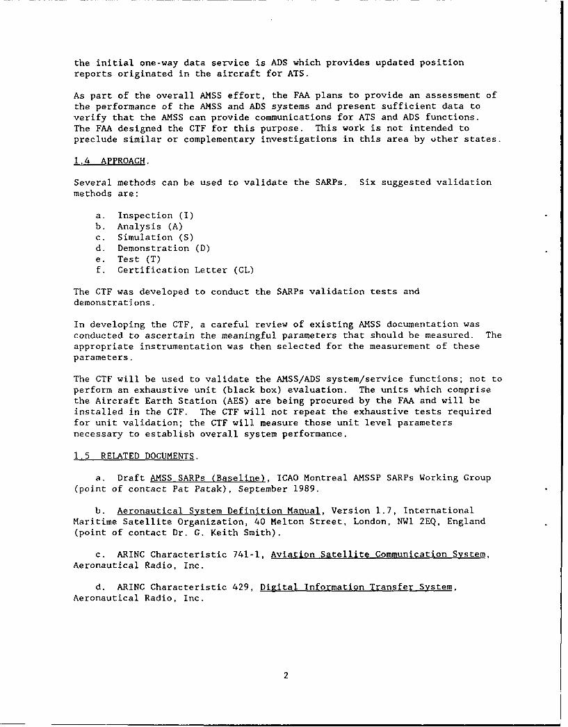
the initial one-way data service is ADS which provides updated positionreports originated in the aircraft for ATS.
As part of the overall AMSS effort, the FAA plans to provide an assessment ofthe performance of the AMSS and ADS systems and present sufficient data toverify that the AMSS can provide communications for ATS and ADS functions.The FAA designed the CTF for this purpose. This work is not intended topreclude similar or complementary investigations in this area by uther states.
1.4 APPROACH.
Several methods can be used to validate the SARPs. Six suggested validationmethods are:
a. Inspection (I)b. Analysis (A)c. Simulation (S)d. Demonstration (D)e. Test (T)f. Certification Letter (CL)
The CTF was developed to conduct the SARPs validation tests anddemonstrations.
In developing the CTF, a careful review of existing AMSS documentation wasconducted to ascertain the meaningful parameters that should be measured. Theappropriate instrumentation was then selected for the measurement of theseparameters.
The CTF will be used to validate the AMSS/ADS system/service functions; not toperform an exhaustive unit (black box) evaluation. The units which comprisethe Aircraft Earth Station (AES) are being procured by the FAA and will beinstalled in the CTF. The CTF will not repeat the exhaustive tests requiredfor unit validation; the CTF will measure those unit level parametersnecessary to establish overall system performance.
1.5 RELATED DOCUMENTS.
a. Draft AMSS SARPs (Baseline), ICAO Montreal AMSSP SARPs Working Group(point of contact Pat Patak), September 1989.
b. Aeronautical System Definition Manual, Version 1.7, InternationalMaritime Satellite Organization, 40 Melton Street, London, NWI 2EQ, England(point of contact Dr. G. Keith Smith).
c. ARINC Characteristic 741-1, Aviation Satellite Communication System,Aeronautical Radio, Inc.
d. ARINC Characteristic 429, Digital Information Transfer System,Aeronautical Radio, Inc.
2

2. COMMUNICATIONS TEST FACILITY.
2.1 FACILITY LOCATION.
The CTF is located in the Flight Operations Building at the FAA Technical
Center, Atlantic City International Airport, New Jersey. Additionalfacilities required for link tests and end-to-end tests include the Comsat
Ground Earth Station (GES) located in Southbury, Connecticut, and the ARINC
Data Network Interface at the FAA Technical Center.
2.2 DESCRIPTION.
The CTF consists of a set of avionics to emulate an AES, a set of automatedtest equipment, and two computers interfaced to the avionics and testequipment to provide signal control and data acquisition functions. A
functional diagram of the CTF equipment is provided in figure 1.
2.2.1 Test Equipment.
The test equipment includes a spectrum analyzer, power meter, frequency
counter, vector modulation analyzer, vector generator, and signal generator,along with miscellaneous couplers, switches and attenuators. A brief
description of the capabilities of the test equipment follows:
a. Spectrum Analyzer, Model HP 8566B. The spectrum analyzer is capableof generating frequency and amplitude plots in the range from 100 hertz (Hz)
to 22 giga-hertz (GHz).
b. Microwave Power Meter, Model HP 438A. The power meter can measure
radio frequency (RF) power up to a maximum frequency of 50 CHz.
c. Vector Signal Generator, Model HP 8780A. This unit is capable of
generating phase and amplitude modulated signals up to a frequency of 3 GHz.
4. RF Signal Generator, Model HP 8673C. This unit is a capable of
generating an RF signal up to 18 GHz.
5. Vector Modulation Analyzer, Model HP 8981A. This unit measures phase
and amplitude of the modulated signal.
All of the microwave test equipment is controllable via the IEEE-488 General
Purpose Interface Bus (GPIB) for remote operation. Other test equipment whichwill be required for testing various SARPs will be rented on a as needed
basis.
In addition to the microwave test equipment, the following data communicationstest equipment also are part of the CTF.
a. Data Error Analyzer, Model 2000 "Firebird" (two each). These units
are capable of measuring bit error rate (BER) on communications links.
b. Protocol Analyzer, Digilog Model 900. This unit performs testing and
emulation of communications protocols.
3

N1-:..
X Power MeterHP 438A
cli
t ............... .... ..An goo :: ...............
X.e. FrequencyCounter
HP 5350Bk
SpectrumLNA/ AnalyzerDiplexer
HP 8566B
SignalGeneratorOn W 30 dB
Attenuator HP 8673C
b HP?79D::,
'0 VectorQ
D C Analyzer
HPA HP 8981A
VV Vectory Generator
D C
Serial toc Parallel
RFUyRF Patch Panel #1
jot, :X..
2
eARINC 429
f kDC nt rfaceDC ... . .... T1200h
.............. . ..........
ARINC 429SD CZy L-4p. Compaq 386
RS-232..... ... ...... .......
0 IEEE-488 Bus0 ARINC 429Modem
0..........
0
D ARINC 429
Baseband Patch Panel MINC 429 Patch Panel
115VAC 400HI I - - I I I - I I - I I4n
rm
0 'd U I ot can
r 0
FIGURE 1. COMMUNICATIONS TEST FACILITY
4
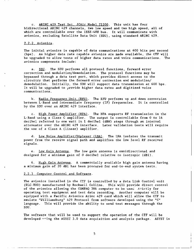
c. ARINC 429 Test Set. JCAir Model Tl200. This unit has fourbidirectional ARINC 429 channels, two low speed and two high speed, all ofwhich are controllable over the IEEE-488 bus. It will communicate withavionics, excluding Satellite Data Unit (SDU), using standard ARINC 429.
2.2.2 Avionics.
The initial avionics is capable of data communications at 600 bits per second(bps). As higher data rate capable avionics are made available, the CTF willbe upgraded to allow tests of higher data rates and voice communications. Theavionics components include:
a. SDU. The SDU performs all protocol functions, forward error
correction and modulation/demodulation. The protocol functions may bebypassed through a data test port, which provides direct access to thecircuitry that performs the forward error correction and modulation/demodulation. Initially, the SDU will support data transmission at 600 bps.It will be upgraded to provide higher data rates and digitized voicecommunications.
b. Radio Frequency Unit (RFU). The RFU performs up and down conversion
between L-Band and intermediate frequency (IF) frequencies. It is controlledby the SDU over an ARINC 429 interface.
c. High Power Amplifier (HPA). The HPA supports RF transmission in the
L-Band using a Class C amplifier. The output is controllable from 0 to 16decibel referred to one watt in 1 decibel (dBW) steps through an internalattenuator over the ARINC 429 interface. Later validation tests will requirethe use of a Class A (linear) amplifier.
d. Low Noise Amplifier/Diplexer (LNA). The LNA isolates the transmitpower from the receive signal path and amplifies the low level RF receivedsignals.
e. Low Gain Antenna. The low gain antenna is omnidirectional and
designed for a minimum gain of 0 decibel relative to isotropic (dBi).
6. Hiagh Gain Antenna. A commercially available high gain antenna having
a minimum gain of 20 dBi has been procured for end-to-end system tests.
2.2.3 Computer Control and Software.
The avionics installed in the CTF is controlled by a Data Link Control unit(DLC-800) manufactured by Rockwell Collins. This will provide direct control
of the avionics allowing the COMPAQ 386 computer to be useu .,trictly foroperating test equipment and test data recording. Another computer will beequipped with a Pacific Avionics Arinc 429 card which will allow the CTF toemulate "Williamsburg" 429 Protocol from software developed using the "C"
language. This will provide the ability to send test messages through theSDU.
The software that will be used to support the operation of the CTF will bedeveloped -- ing the ASYST 3.0 data acquisition and analysis package. ASYST is
5

an interpreted software development and environment based on the programminglanguage FORTH.
The ASYST language was selected bec-use of its extensive capabilities in dataacquisition and analysis and its G2IB control functions.
ASYST programs will be used primarily for tests which require repetitivemeasurements and/or extensive analysis and data reduction.
2.3 GROUND EARTH STATION.
The GES, located in Southbury, Connecticut, supports AMSS protocols andservices. The GES also records billing information, and interfaces with theARINC Data Network Services (ADNS) front-end processor. The front-endprocessor converts the AMSS messeges to the proper format for routing on theADNS network.
Future plans require the installation of additional equipment at theCommunications Satellite Corporation (COMSAT) earth station such as, an ABPSKmodem, a computer, and test instrumentation. The modem will interface to theGES at IF frequencies and can be operated using software which emulates theAMSS protocols. An overview of the end-to-end test configuration is shown infigure 2.
2.4 CALIBRATION.
All test equipment will be calibrated using standards traceable to theNational Institute of Technology and Standards. The calibration will behandled through FAA administrative channels and will be repeated periodically.The calibration records will be kept with the equipment.
3. TEST PROGRAM DESCRIPTION.
3.1 PROGRAM DESCRIPTION.
The tests conducted will be used to validate the parameters specified in theAMSS SARPs and to provide the data required to assess system performance. Agiven SARPs requirement will be considered validated if equipment satisfyingthe requirement provides adequate AMSS system performance. The BER will beused as a measure of adequate system performance. The test program is dividedinto four phases.
a. Phase I tests will verify the proper function of test equipment andtest software.
b. Phase II tests will verify the opera-ion and performance of theavionics without RF propagation.
c. Phase IIl tests will verify the SARPs requirements related to thesignal-in-space and satellite link performance.
6

Z 0a
0~ in -.w- E-"-L UH r IA
u 0-
0~
3t, .z) E '
c 0 rC'0 0-0 14 T : 4
-0 00
0 x E)
I IT 0.
0 -0 "C 0-3
u 94 *0H0
V
u0z
4) 'J4) -0 7

d. Phase IV tests will evaluate end-to-end system performance. The end-to-end functions include, but are not limited to, ADS and digitized voicecommunications.
AMSS protocols will be evaluated as a separate task using simulation routines.The simulations will test the protocols defined in the SARPs for theirfunctionality and effect on channel loading. The results of the simulationswill determine specific protocol tests to be conducted in the CTF.
A brief list of the tests to be conducted in each phase is provided insections 3.1.1 through 3.1.4. A SARPs Validation Test Matrix indicating themethod of verification is provided in appendix A. Validation or verificationby analysis may include the review of previous test data and manufacturersupplied data and/or certification letters. Appendix B contains a descriptionof the tests that will be conducted in the CTF to validate the ICAO AMSSSARPs. The descriptions include the test configuration, data to be recorded,performance criteria, and SARPs requirement verified.
3.1.1 Phase I Tests.
These tests will verify that the test equipment is correctly interfaced to theIEEE-488 and ARINC 429 buses. Phase I tests include, but are not limited to:
a. Test I-1: ASYST Software Control of Test Equipment.
b. Test 1-2: ASYST Software Control of ARINC 429 Interface.
c. Test 1-3: Performance Verification of Directional Coupler.
d. Test 1-4: Insertion Loss Measurements of Test Access Points.
e. Test 1-5: Insertion Loss Measurements of Long Cable Runs.
f. Test 1-6: Return Loss Measurements from HPA output to antennas.
3.1.2 Phase II Tests.
These tests will verify the operation and performance of the avionics in alaboratory setting without using a satellite link. The tests are conducted byterminating the transmitter RF output into a 50 ohm load. Avionicsperformance capabilities will be measured to establish a baseline. Phase IItests include, but are not limited to:
a. Test II-1: Spectral Analysis.
b. Test 11-2: Third Order Intermodulation Products.
c. Test 11-3: Power Measurements.
d. Test 11-4: Transmit Phase Noise Measurement.
e. Test 11-5: Transmit Frequency Measurements.
8

3.1.3 Phase III Tests.
These tests will be conducted over a satellite link. Some RF parameter testswill be repeated to validate them under actual operating conditions. ThePhase III tests include the verification of link and network protocols. Theprotocols will be validated under operational conditions (i.e., over thesatellite link) after the functional protocols tests using simulations arecomplete. Phase III tests include, but are not limited to:
a. Test III-1: Transmit/Received Spectrum Analysis.
b. Test 111-2: Received Phase Noise Measurements.
c. Test 111-3: Demodulator Performance.
d. Test 111-4: Channel Performance vs Power.
e. Test 111-5: Received Signal Measurements.
3.1.4 Phase IV Tests.
Phase IV tests are end-to-end system level performance tests. They willrequire the use of the CTF, satellite link, and a terrestrial network. PhaseIV tests being planned at this time include, but are not limited to:
a. Test IV-l: ADS Message Time Delay.
b. Test IV-2: Low Data Rate Voice Coder/Decoder (CODEC) Evaluation.
3.2 DATA REDUCTION AND ANALYSIS.
Test data will be collected by the COMPAQ 386 computer and will be reduced toa form which will allow for comparison with SARPs requirements by the ASYSTsoftware. The data will be analyzed to determine the SARPs requirement hasbeen satisfied.
3.3 TEST REPORTS.
At the end of each test phase a test report will be prepared which will
contain the results of all tests performed. If necessary for AMSS systemperformance, a recommendation to change a given SARPs requirement will bemade.
4. SCHEDULE.
Phases I through III tests are planned to be completed in one calendar yearwith an anticipated start date in the second quarter of 1991. A detailedschedule will be supplied at a later date.
5. AREAS OF RESPONSIBILITY.
ACD-330: Responsible for all Technical Center activities. Will monitor SARPstests, ADS tests, and conduct flight tests. Will be responsible for obtaining
9

FCC licenses and coordinating the Memoranda of Agreement between the FAA andother organizations.
ARD-300: Responsible for program management and funding for satellitecommunications projects. Will provide the U.S. ICAO member to the AMSS paneland the representative to the RTCA committees.
CTA: Responsible to ACD-330 in SARPs testing activities. Will provide testengineering services, develop test plans, conduct tests, perform dataanalysis, and provide test reports.
COMSAT: Responsible for obtaining free use of INMARSAT space segment and forproviding FAA access to the GES for testing.
CTF SCHEDULE
Install Test Equipment in Racks 8/90Receive Avionics 9/90Install Avionics 9/90Install NEMA Enclosure on Roof 9/90Draft Test Procedures Document 4/91MOU with COMSAT 7/90Begin Phase I Tests 5/91Phase I Test Report Draft 6/91Begin Phase II Tests 7/91Phase II Test Report Draft 8/91Begin Phase III Tests Schedule TBD pendingPhase III Test Report Draft the availability of
voice capable avionics.
10

APPENDIX A
SARPs VALIDATION TEST MATRIX

Appendix A contains an AMSS SARPs Validation Cross-Reference Matrix allowing
for the tracking of SARPs requirements and recommendations as well as the
proposed method validation to be utilized for these requirements. At present
there are five methods of validation:
1. Inspection (I) Verify by physical inspection
2. Analysis (A) Verify by analysis of the manufacturer's/service provider's test data and software
audits
3. Simulation (S) Verify by simulation/emulation of systemand/or simulation of performance and
protocols
4. Demonstration (D) Verify that capability exists
5. Test (T) Verify by component or system testing
6. Certification Letter (CL) Certification Letter from avionicsmanufacturer stating compliance with SARPs
(Parameters requiring a certification
letter are under review)
A-i

AMSS SARPs VALIDATION CROSS-REFERENCE MATRIX
Validation MethodSARPsParagraphNumber Requirement N/A I A S D T CL
1. Definitions and SystemCapabilities X
1.1 Channel Types X1.1.1 P-Channel X1.1.2 R-Channel X1.1.3 T-Channel X1.1.4 C-Channel X1.2 System Capabilities X1.2.1 Level 1 X1.2.1.1 [Level 1 Requirement] X1.2.1.2 [P-Channel Requirement] X2. Broadband RF Characteristics X2.1 Frequency Bands X2.1.1 Use of AMS(R)S Bands X2.1.1.1 [Priority of AMS(R)S messages
Part 2/5.1.8] X2.1.2 To Aircraft X2.1.2.1 [Receive in 1544-1555 MHz Band] X2.1.2.2 [Receive in 1555-1559 MHz Band] X2.1.2.3 [Receive in 1530-1544 MHz Band] X2.1.3 From Aircraft X2.1.3.1 [Transmit in 1645.5-1656.5 MHz
Band] X2.1.3.2 [Transmit in 1656.5-1660.5 MHz
Band] X2.1.3.3 [Transmit in 1626.5-1645.5 MHz
Band] X2.1.4 Tuning Increments X2.1.4.1 [2.5 kHz tuning increments] X2.1.4.2 [Channel assignment/tuning
control] X2.1.5 Channel Numbering X2.1.5.1 [C Channel number] X X2.1.5.2 [CC Channel number] X X2.2 Frequency accuracy and
compensation X2.2.1 Aircraft Earth Station X2.2.1.1 [Doppler Correction] X X2.2.2 GES [Aeronautical Earth Station] X2.2.2.1 [GES Frequency compensation] X X2.3 Reserved Channels X2.3.1 [Manual control of reserved
channels] X2.4 Aircraft Earth Stations X
A-2

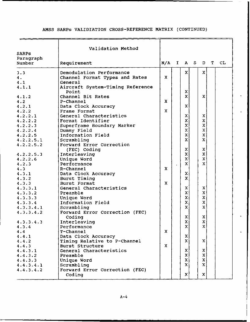
AMSS SARPs VALIDATION CROSS-REFERENCE MATRIX (CONTINUED)
Validation MethodSARPsParagraphNumber Requirement N/A I A S D T CL
2.4.1 General Antenna Characteristics X2.4.1.2 Reference Coverage Volume X2.4.1.2.1 (Recommended Coverage Volume] X X2.4.1.3 Axial Ratio X2.4.1.4 Polarization X2.4.1.5 Antenna Switching X X2.4.2 Low Gain Antenna Subsystems X2.4.2.1 Gain X2.4.3 High Gain Antenna Subsystems X2.4.3.1 Gain X2.4.3.2 Discrimination X2.4.3.3 Antenna Boresight Steering X2.4.3.3.1 Antenna Orientation X2.4.3.4 Satellite Acquisition X X2.4.3.5 Phase Discontinuity X2.4.4 Receiver Requirements X2.4.4.1 Gain-to-Noise Temperature
Ratio X2.4.4.2 Dynamic Range X X2.4.4.3 Received Phase Noise X X2.4.5 Transmitter Requirements X2.4.5.1 EIRP Limits X X2.4.5.2 EIRP Controls X X2.4.5.3 Carrier Off Level X X2.4.5.4 Spurious Outputs X X2.4.5.4.1 [Spurious Outputs/harmful
Interference] X2.4.5.5 Harmonic Outputs X X2.4.5.6 Intermodulation Products X X2.4.5.7 Phase Noise X X2.4.5.8 Power Stability X X3. RF Channel Characteristics X3.1 Modulation Method X3.1.1 For Data Rates 2.4 Kbits/s and
below X3.1.1.1 [A-BPSK Modulation] X X3.1.1.2 [Pulse-shaping filters] X X3.1.2 For Data Rates Above 2.4 Kbit/s X3.1.2.1 [A-QPSK Modulation] X X3.2 Bounds on Radiation Power
Spectral Density X3.2.1 From Aircraft X X3.2.2 To Aircraft X
A-3
AMSS SARPs VALIDIATION CROSS-REFERENCE MATRIX (CONTINUED)
Validation MethodSARPsParagraphNumber Requirement N/A I A S D T CL
3.3 Demodulation Performance X X4. Channel Format Types and Rates X4.1 General4.1.1 Aircraft System-Timing Reference
Point X4.1.2 Channel Bit Rates X X4.2 P-Channel X4.2.1 Data Clock Accuracy X4.2.2 Frame Format X4.2.2.1 General Characteristics X X4.2.2.2 Format Identifier X X4.2.2.3 Superframe Boundary Marker X X4.2.2.4 Dummy Field X X4.2.2.5 Information Field X X4.2.2.5.1 Scrambling X X4.2.2.5.2 Forward Error Correction
(FEC) Coding X X4.2.2.5.3 Interleaving X X4.2.2.6 Unique Word X X4.2.3 Performance X X4.3 R-Channel X4.3.1 Data Clock Accuracy X4.3.2 Burst Timing X4.3.3 Burst Format X4.3.3.1 General Characteristics X X4.3.3.2 Preamble X X4.3.3.3 Unique Word X X4.3.3.4 Information Field X X4.3.3.4.1 Scrambling X X4.3.3.4.2 Forward Error Correction (FEC)
Coding X X4.3.3.4.3 Interleaving X X4.3.4 Performance X X4.4 T-Channel X4.4.1 Data Clock Accuracy X4.4.2 Timing Relative to P-Channel X X4.4.3 Burst Structure X4.4.3.1 General Characteristics X X4.4.3.2 Preamble X X4.4.3.3 Unique Word X X4.4.3.4.1 Scrambling X X4.4.3.4.2 Forward Error Correction (FEC)
Coding X X
A-4

AMSS SARPs VALIDATION CROSS-REFERENCE MATRIX (CONTINUED)
Validation MethodSARPsParagraphNumber Requirement N/A I A S D T CL
4.4.3.4.3 Interleaving X X4.4.4 Performance X X4.5 C-Channel X4.5.1 Data Clock Accuracy X4.5.2 Transmission Formats X4.5.2.1 To Aircraft X X4.5.2.2 Preamble X X4.5.2.3 From Aircraft X4.5.3 Frame Format X4.5.3.1 Unique Word X X4.5.3.2 Dummy Field X4.5.3.3 Information Field X4.5.3.3.1 Information Field Structure
Including Sub-band dataField X X
4.5.3.3.2 Scrambling X X4.5.3.3.3 Forward Error Correction (FEC)
Coding X X4.5.3.3.4 Interleaving X X4.5.4 Performance X4.6 Other Channels (TBD) X
5.X
To Be Supplied
10.X
A-5
APPENDIX B
SARPs TEST DESCRIPTION

TEST II-I: SPECTRAL ANALYSIS.
PURPOSE.
1. Validate the transmit spectrum requirements defined in SARPs for theaircraft earth station direct measurement.
TEST CONFIGURATION.
5 0 ohmLoad
Tx L-Band
LNADiplexe: HP 8566B
Spectrum . \
Directional ----- ze--\
Coupler
30dB R
Attenuator atch
TxL-Band
T L_Tx L-BDLC-800
RF 001 MS-DOS~computer
Tx IF Bus
SDU Control and 429 Patch
FIGURE II-I. SPECTRAL ANALYSIS TEST ANALYSIS
B-i
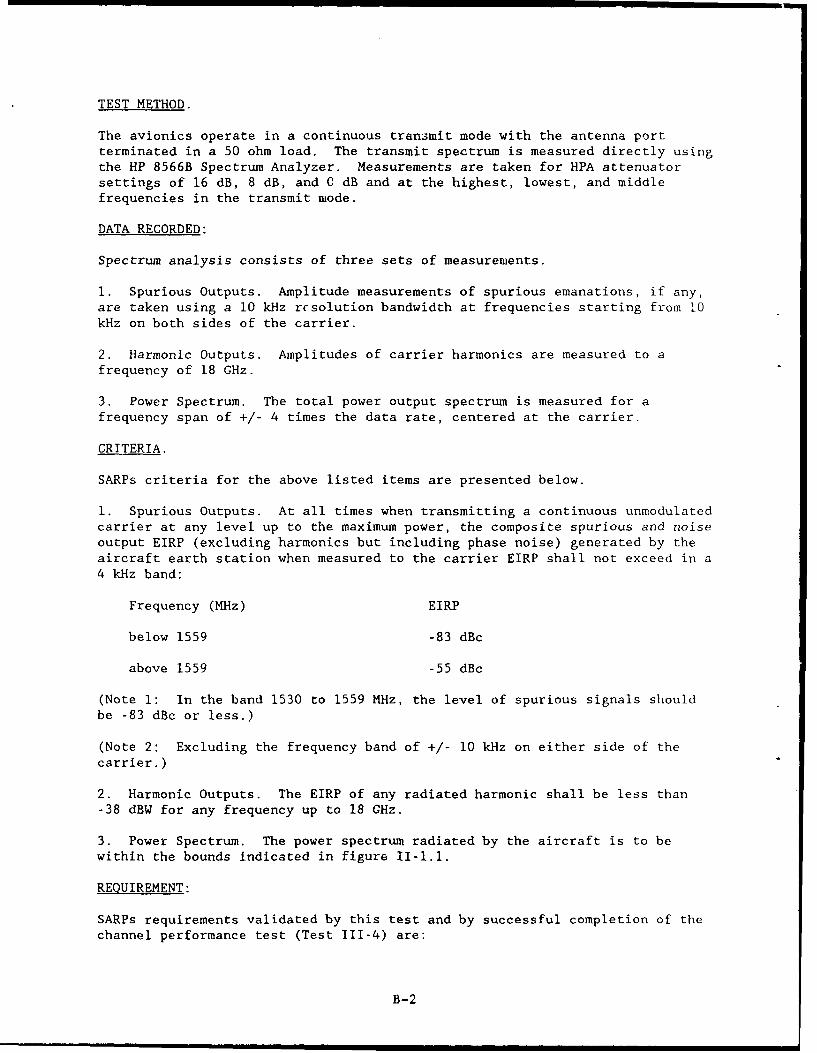
TEST METHOD.
The avionics operate in a continuous transmit mode with the antenna portterminated in a 50 ohm load. The transmit spectrum is measured directly usingthe HP 8566B Spectrum Analyzer. Measurements are taken for HPA attenuatorsettings of 16 dB, 8 dB, and 0 dB and at the highest, lowest, and middlefrequencies in the transmit mode.
DATA RECORDED:
Spectrum analysis consists of three sets of measurements.
1. Spurious Outputs. Amplitude measurements of spurious emanations, if any,are taken using a 10 kHz resolution bandwidth at frequencies starting from 10kHz on both sides of the carrier.
2. Harmonic Outputs. Amplitudes of carrier harmonics are measured to afrequency of 18 GHz.
3. Power Spectrum. The total power output spectrum is measured for afrequency span of +/- 4 times the data rate, centered at the carrier.
CRITERIA.
SARPs criteria for the above listed items are presented below.
1. Spurious Outputs. At all times when transmitting a continuous unmodulatedcarrier at any level up to the maximum power, the composite spurious and noiseoutput EIRP (excluding harmonics but including phase noise) generated by theaircraft earth station when measured to the carrier EIRP shall not exceed in a4 kHz band:
Frequency (MHz) EIRP
below 1559 -83 dBc
above 1559 -55 dBc
(Note 1: In the band 1530 to 1559 MHz, the level of spurious signals shouldbe -83 dBc or less.)
(Note 2: Excluding the frequency band of +/- 10 kHz on either side of thecarrier.)
2. Harmonic Outputs. The EIRP of any radiated harmonic shall be less than-38 dBW for any frequency up to 18 GHz.
3. Power Spectrum. The power spectrum radiated by the aircraft is to bewithin the bounds indicated in figure II-1.1.
REQUIREMENT:
SARPs requirements validated by this test and by successful completion of thechannel performance test (Test 111-4) are:
B-2
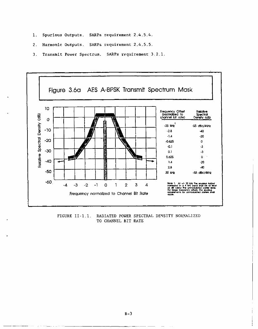
1. Spurious Outputs. SARPs requirement 2.4.5.4.
2. Harmonic Outputs. SARPs requirement 2.4.5.5.
3. Transmit Power Spectrum. SARPs requirement 3.2.1.
Figure 3.6a AES A-BPSK Transmit Spectrum Mask
10Mr~ecyOfet Relative
ca Cnnn=edo to spectralV - channel btrate) Denaly (aB)
-~-35 IfiZ -55 dBc/4;k-z*: -10 -2.8 -40
0-1.4 -20
.t= -20 -0.626 0
I0r I -0.1 -3"'30 0.1 -3
2 0N w0.625 0.9 -40 1.4 -20
f'- - 2.8 -40
-50 35 kitz -55 d8c/4dlz
-4 -3 -2 -1 0 1 2 3 4 Ntae.A/in o 4 Iftbn of lecitM5 dO belo fw rited cadoMvFa i~r freova-Cy offt. " so~v~o~s
Frequency normalized to Channel Bit Rate rSrt O YC.d~ oe ~
FIGURE II-1.1. RADIATED POWER SPECTRAL DENSITY NORMALIZEDTO CHANNEL BIT RATE
B-3

TEST 11-2: THIRD ORDER INTERMODULATION DISTORTION.
PURPOSE.
To validate Third Order Intermodulation products requirements defined by SARPs
for aircraft earth station with linear high power amplifiers by direct
measurement.
TEST CONFIGURATION.
tAnalyzer XHP8566B ,
LNA /N~iplexe ///
Directional 30 D
Coupler R U
Panel| #2/Signal ///////
Generator /
HP Signal l//
Gen e rat o r /////
I RFU Combiner
FIGURE 11-2. THIRD ORDER INTERMODULATION DISTORTION TEST ANALYSIS
B-4

TEST METHOD.
The avionics will operate in a transmit mode with the antenna port feeding
into the spectrum analyzer. Two signal generators will provide dual IFcarriers into the RFU at the low, middle, and high end of the transmit IF
range.
DATA RECORDED.
Third Order Intermodulation Distortion will be measured with 10 kHz resolution
bandwidth with frequencies starting from 10 kHz of the two carriers.
CRITERIA.
SARPs Criteria for the above item is presented below.
1. Intermodulation products. The EIRP of any intermodulation product shallbe less than [ j dBW.
(Note: For aircraft stations employing linear amplifiers when the transmitteris driven by two equal carriers each producing output power of 10.5 dbW at the
input to the antenna, the individual third order IMD products shall not exceed[14.5 dbWj at the input to the antenna.)
Further reduction is expected from operational actions including optimization
of AES antenna beam pointing, channel assignment within the spectrum,
satellite spacing, and EIRP control.
REQUIREMENT.
SARPs validated by this test:
1. Intermodulation Products. SARPs requirement 2.4.5.6.
B-5

TEST lII3: POWER MEASUREMENTS.
PURPOSE.
1. Validate the power requirements defined in SARPs for the aircraft earth
station by direct measurement operating the avionics into a dummy load.
2. Verify the power output capability of the avionics.
TEST CONFIGURATION.
50 OhmLoad
Tx L-Band
Lplee HP-438ADilxrPower
D~rcioa oMeter
ietonal Rq
Coupler
30dB PatchS E SIttenuator PanelTxL-Band #2 \
0DLC-800 00L-Band 001
RF MS-DOS \
I o p t r IEEE-488ITx IF -1Bus
SDU .Control and42Pac"Data Panel
FIGURE 11-3. POWER MEASUREMENTS TEST ANALYSIS
B-6

TEST METHOD.
The avionics operate in continuous transmit mode with the antenna port
terminated into a 50 ohm load. The power output is measured using the HP 438A
Power Meter through a directional coupler at the antenna port and 30 dB of
attenuation. Measurements are taken for HPA attenuator settings of 16 dB,
8 dB, and 0 dB at the highest, lowest, and middle frequencies in the transmit
mode.
DATA RECORDED.
Power measurements consist of two items:
1. Power Stability. The output power of the AES is measured periodically.
2. Carrier Off Level. Measurements of the power emitted by the AES, when it
is not transmitting, a carrier is made.
CRITERIA.
SARPs criteria for the above listed items are presented below.
1. Power Stability. The AES must maintain the commanded output power of the
carrier to within +/- 1 dB.
2. Carrier Off Level. The total power emitted by the AES when not
transmitting a carrier shall be no more than -24 dBW.
REQUIREMENT.
SARPs requirements validated by this test and by successful completion of the
channel performance test (Test 111-4) are:
1. Power Stability. SARPs requirement 2.4.5.8.
2. Carrier Off Level. SARPs requirement 2.4.5.3.
B-7

TEST 11-4: TRANSMIT PHASE NOISE MEASUREMENTS.
PURPOSE.
1. Validate the phase noise requirements defined in SARPs for the aircraft
earth station by direct measurement.
TEST CONFIGURATION.
SpectrumAnalyzer
MS-DOS
LwNoise Reference OsoeCmue
Bus
RFU DLC- 800
1001
BasebandPatch Panel] 429
FIGURE 11-4. TRANSMIT PHASE NOISE MEASUREMENT TEST ANALYSIS
B-8

TEST METHOD.
The avionics operate in a continuous transmit mode. The phase noise ismeasured by taking RFU output directly into an L-Band Mixer which has a second
input from a Low Noise Reference source. The mixer output is applied to a Low
Pass Filter whose output is monitored by an oscilloscope. The filter outputis applied to a Low Noise Amplifier and measured on a spectrum analyzer.
DATA RECORDED.
Phase noise power spectral density measured on the modulated carrier using theHP 8566B Spectrum Analyzer.
CRITERIA.
The phase noise induced on a modulated carrier must not exceed the power
density given in SARPs figure 11-4.
REQUIREMENT.
SARPs requirement 2.4.5.7 is validated by this test.
.30........................ ..... ..... .........
. .. . . . . . . . . . . .° • . . . -7°° ., , ... . . , . . . . . . . . . .
. ..... ... .. ... .. .... ..; .. . ... . ....... ..... .. ..:... ... . 0 .... .. .. . .. .... ••• •.. .. " .. .. . ... .. .;..... 1;.-.. ... -• -. -.. . ... ..... ...... ... .." :.•; ; ..
........... .... ..... ...
. ...:. ~. ... ..... ...... ...... .. .. ..!. .- .... ... .. . , ... .... .. ..... ... ....... " " : ... ... .. . ........... " ' " ' " " ' .. ...... ..... .. .. " " ; ;
." .. . ..... . . . . . . . I.. . .... .. ...
60
.. .. . .. .. .. . . l " : " ' " " . . .. .... ... . ..... .' " ' ' ' ; : ' ....... .. . . . . . .... .." ' ' ' '; :
.......... ..... .. • . ; ........... ......... .. ... .... . i . ...... ; ........ -... ... "
.. . .. .... .. . . •,' ". •"......:. . ... .. . ..... -.... :.. ;. :.. " .. .. ...... . ...........•..........~.70
. .0 ... ... . .. . . .. .
.. .. ........ I. -.-....... ........... .... ... .. : ....0 ... .. . .......... * ..... !.... :. .... .. '. . ..
1 03 1 too too1o=
O B-9f PROM CARIN HE=
B -9

TEST 11-5. TRANSMIT FREQUENCY MEASUREMENTS.
PURPOSE.
1. Verify that the transmit frequency of the avionics meets the tolerancerequirements defined in the SARPs for the aircraft earth station.
2. Verify that the avionics are capable of tuning the transmit frequency inthe steps required by SARPs.
TEST CONFIGURATION.
50 Ohm
Load
t Tx L-Band
NA
Directional 30 db AttenuatorCoupler
Tx L-Band
HPA
Tx L-Band l HP 5350B \\\El ----4Frequency .
_DC Counter
RF k
Panel \\_#2 I
STx IF DLC-800
Cont rol 001
SU adDt ARINC 429 XPatch
,,~ ~ {LPanel, \
MS-DOS %
IEEE-488
Bus
FIGURE 11-5. TRANSMIT FREQUENCY MEASUREMENTS TEST ANALYSIS
B-10

TEST METHOD.
The transmit frequency of the avionics is measured and any deviations arerecorded. The difference between adjacent commanded frequencies in the RFU ismeasured. Tuning across the entire range of the transmit frequency bands willbe recorded.
DATA RECORDED.
Expected frequency and actual frequency of the transmit L-Band signal, priorto and after being amplified by the HPA, is recorded. The difference iscalculated and recorded.
CRITERIA.
1. The frequency of the transmission from the aircraft earth station shallnot vary from the nominal channel frequency by more than 350 Hz.
2. The channels are allocated throughout the band in increments of 2.5 kHz.
REQUIREMENT.
1. Transmission Frequency Accuracy: SARPs requirement 2.2.1.1.
2. Tuning Increments: SARPs requirement 2.1.4.1.
3. Transmit Frequency Bands. SARPs requirements 2.1.3.1 to 2.1.3.3.
B-11
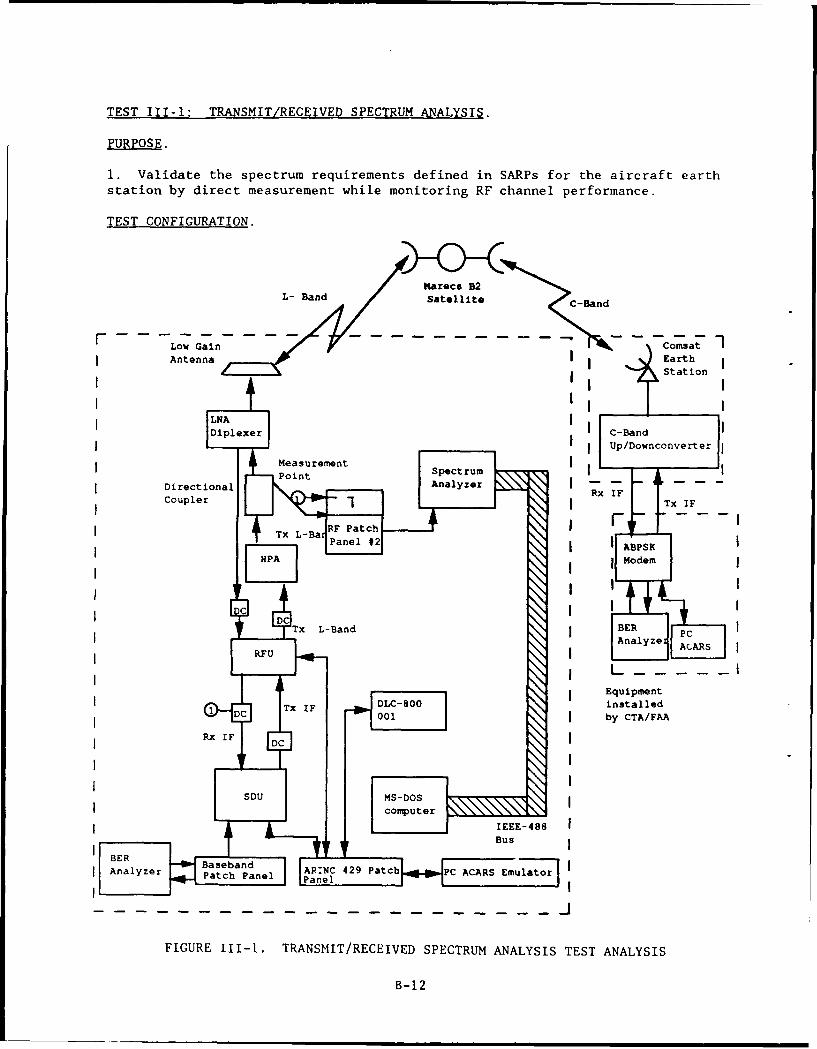
TEST II1-1: TRANSMIT/RECEIVED SPECTRUM ANALYSIS.
PURPOSE.
1. Validate the spectrum requirements defined in SARPs for the aircraft earthstation by direct measurement while monitoring RF channel performance.
TEST CONFIGURATION.
Maraca B2L- Band Satellite C-Band
Low Gain ComsatAntenna IEarth
LNA cBn
Mesuemn Up/Downconvre
Directional AnayzeCoupler I xI Tx IF
Tx L-a an l # ABPSKjmodem
DCBER PAlyzeAAS
Tx----------
TIFDLC-800 installedDC001 j by CTA/FAA
Analzer Baseband RNC 2 ac CAASEuaoAnlzr Patch Panel anel CI2 ac CR -
FIGURE Ill-i. TRANSMIT/RECEIVED SPECTRUM ANALYSIS TEST ANALYSIS
B- 12

TEST METHOD.
The avionics operate in continuous transmit mode. The transmit spectrum is
measured directly at the antenna port using the HP 8566B Spectrum Analyzer.
Measurements are taken for HPA attenuator settings of 16 dB, 8dB, and 0 dB and
are recommended at the highest, lowest, and middle frequencies in the transmit
band. The actual frequencies for testing is determined by MOA with COMSAT.
DATA RECORDED.
Spectrum analysis consists of three measurement sets.
1. Spurious Outputs. Amplitude measurements of spurious emanations, if any,are taken using a 10 kHz resolution bandwidth at frequencies starting from 10
kHz above and below the carrier.
2. Harmonic Outputs. Amplitude of carrier harmonic no greater than 18G Hzwill be measured.
3. Power Spectrum. The total power output spectrum is measured over a
frequency span of +/- 4 times the data rate centered at the transmit or
receive carrier frequency.
4. Bit Error Rate (BER). BER is measured in order to verify systemperformance, using an error analyzer at the ground earth station. An operator
at the earth station records the data.
CRITERIA.
SARPs criteria for the above listed items are presented below.
1. Spurious Outputs. At all times when transmitting a continuous unmodulated
carrier at any level up to the maximum power, the composite spurious and noise
output EIRP (excluding harmonics but including phase noise) transmitted by the
aircraft earth station when measured relative to the carrier EIRP must not
exceed in a 4 kHz band:
Frequency (MHz) EIRP
below 1559 -83 dBc
above 1559 -55 dBc
(Note 1: In the band 1530 to 1559 MHz, the level of spurious signals should
be -83 dBc or less).
(Note 2: Excluding the frequency band of +/- 10 kHz on either side of thecarrier.)
2. Harmonic Outputs. The EIRP of any radiated harmonic must be less than -38
dBW for any frequency up to 18 GHz.
B-13

3. Power Spectrum. The power spectrum radiated by the aircraft must fall
within the bounds indicated in SARPs figure 111-1.1.
4. Channel Performance. The overall physical layer is configured such that
the average bit error rate is 1l-5 or less after forward error correction.
REQUIREMENT.
SARPs requirements validated by this test are:
1. Spurious Outputs. SARPs requirement 2.4.5.4.
2. Harmonic Outputs. SARPs requirement 2.3.5.5.
3. A-BPSK Modulation. SARPs requirement 3.1.1.1.
4. A-QPSK Modulation. SARPs requirement 3.1.2.1.
5. Transmit Power Spectrum. SARPs requirement 3.2.1.
6. Bit Error Rate. SARPs requirement 4.4.4.
10- - -- - -
__Frequen~cy Offset Relattveco(nonlzed to spectral
'a 0 - channe bftrcte) Derdsty dB),
- - . - - - -35 kit -55 d~cI4kH-
ID -10 -. 4At-1.8 -201
-0.625 0
Q. - - - -- -0.1 -3(D 3 0.1 -3
Z ~ -- 0.625 0
1.4A -20
-02.8 -40
-60 35 ki-z -55 dBC/4kft
-4 -3 -2 -1 0 1 2 3 4 Nf .A 5U h xcna
For "Ver freauercy omfets. " eo x
Frequency normalized to Channel Bit Rote DW-fflWvoe am*X
B-14

TEST 111-2: RECEIVED PHASE NOISE REQUIREMENTS.
PURPOSE.
1. Validate the phase noise limitation defined in SARPs for the aircraftearth station by direct measurement on the modulated received carrier.
TEST CONFIGURATION,
L- Band arece B2Satellite C-Band
Antnn Station
Diplexer ~l c-BandII Upconverter
RxLBadIL - - I
jI ABPSK
HP 8566B Modem
Mi e Lo Passnnalyze
DLC-800PC ACARSSDU OE I IEmul ator
BasebandinstalledPatch anel I EEE-488 Iby CTA/FAA
E nl Patch Panel
ArbitraryI
L Test Mesage
FIGURE 111-2. RECEIVED PHASE NOISE MEASUREMENTS TEST ANALYSIS
B- 15

TEST METHOD.
The avionics operate in normal mode. Frequencies to be tested are determinedby MOA with COMSAT.
DATA RECORDED.
Phase noise power spectral density is measured on the modulated carrier usingthe HP8566B Spectrum Analyzer.
CRITERIA.
The phase noise induced on a modulated carrier must not exceed the powerdensity given in SARPs figure 111-2.1.
REQUIREMENT.
SARPs requirement 2.4.4.3 and 4.1.2 is validated by successful completion ofthis test and of the channel performance test (Test 111-4).
" .. . . . . .. . . . . . . .
so ~ ~~ ~ .... ............... ." .
-.. .........
410 00
O UET PROM CAXAM IN MxITZ
B-16

TEST 111-3: DE1OPULATOR PERFORMANCE.
PURPOSE.
Validate the demodulator performance in the presence of two adjacent carriers
5 dB than the desired carrier.
TEST CONFIGURATION.
The test method for this requirement is under investigation. Alternative
being evaluated include the use of a second set of avionics, a vector signal
generator and a mixer to generate the adjacent carriers and add them to the
received signal at the SDU IF input. Another method would be to have COMSAT
assist us by sending us two adjacent carriers at 5 dB higher on the R and T
channels and check BER. Also, it would be quite simple to simulate a
multipath fade to further test overall demodulator performance.
B-17
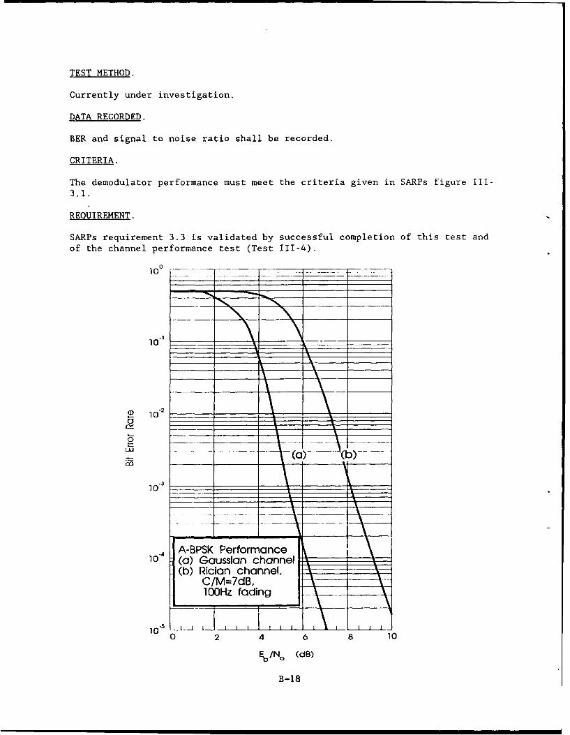
TEST METHOD.
Currently under investigation.
DATA RECORDED.
BER and signal to noise ratio shall be recorded.
CRITERIA.
The demodulator performance must meet the criteria given in SARPs figure III-3.1.
REQUIREMENT.
SARPs requirement 3.3 is validated by successful completion of this test andof the channel performance test (Test 111-4).
10-1 __ _ ___ __ _ _ __ _ _
0 102___ ______ _
10- (a) Gaussian channel
0-5 ..7
Eb/,(dB)
B- 18

TEST 111-4: CHANNEL PERFORMANCE VS. POWER.
PURPOSE.
1. Validate the channel performance requirements defined in SARPs for theaircraft earth station for the highest, middle and lowest transmitter powersettings.
2. Validate the SARPs requirements measured in tests 11-1 through 11-4 bynoting no adverse effect on channel performance.
TEST CONFIGURATION.
- - - -- - - - - - - - - - - -Station
Low Gain IAnen Ij an
1Rx/Tx L-Band I /ownconverterj
Diplexer Rx I x I
AA ABPSK
30dB P 438 Modem
Rx L-Ban HPA LI---
TxE L-an
RU001 MS-DOSL-- ----computer Equipment
BUS IF T FIE-8 installedby CTA/FAA
Panl PRS CRmul atorli
ArbritraryTest Message
iPatch PanelI
FIGURE 111-4. CHANNEL PERFORMANCE VS. POWER TEST ANALYSIS
B-19

TEST METHOD.
The avionics will operate in continuous transmit mode. The power output ismeasured using the HP 438A Power Meter through a directional coupler at theantenna port and a 30 dB attenuator. BER measurements will be taken for HPAattenuator settings of 16 dB, 12 dB, 8 dB, 4 dB, and 0 dB at the highest,middle, and lowest frequencies in the transmit band. The exact frequencies tobe tested will be determined by MOA with COMSAT.
DATA RECORDED.
1. Transmitter Power. The output power of the AES will be measured andrecorded.
2. BER. BER will be measured for each commanded power setting.
CRITERIA.
The overall physical layer shall be configured such that the average BER in10-5 or less after forward error correction.
REQUIREMENTS.
1. Channel Performance. SARPs requirement 2.4.5.8.
2. Cf Channel Number. SARPs requirement 2.1.5.2.
B-20

TEST 111-5: RECEIVED SIGNAL MEASUREMENTS.
PURPOSE.
Validate the spectrum requirements and frequency accuracy defined in SARPs for
the satellite/GES by direct measurement.
TEST CONFIGURATION.
Low Gain Satellite
Antenna Comsat 1
Rx L-Band IEarthStation
LNADiplexer C-Band
Downconverter
H 5 Tx IF
Counter ABPSK IRx AI Modem
I ,INkk Spectrum DCDLC-800
PatchBERPanelAnalyzer
SDU
ARINC 429 Patc L _
8EquipmentBus installed
by CTA/FAA
-- qMS-DOS I
\ \kcomputer IPatch Panell
BER
Analyzer
FIGURE 111-5. RECEIVED SIGNAL MEASUREMENTS TEST ANALYSIS
B-21

TEST METHOD.
The avionics will operate in receive mode. The receive spectrum in measured
directly at the LNA output using the HP 8566B Spectrum Analyzer. The exact
frequency of the received signal will be measured by the HP 5350B frequency
counter. The frequencies for testing will be determined by MOA with COMSAT.
DATE RECORDED.
1. The spectrum of the received signal will be measured for a frequency span
of +/-4 times the data rate centered at the carrier frequency.
2. The frequency of the expected receive signal and the frequency of the
actual receive signal will be recorded.
CRITERIA.
SARPs criteria for the above listed items are presented below.
1. The power spectrum for the signal transmitted by the CES shall be withinthe bounds shown in figure 111-6.1.
2. The frequency of the to-aircraft signal shall be within 260 Hz of the
nominal channel frequency.
REQUIREMENT.
SARPs requirements validated by this test are:
1. Receive Power Spectrum. SARPs requirement 3.2.2.
2. Receive Signal Frequency Accuracy. SARPs requirement 2.2.2.1.
3. Cu Channel number. SARPs requirement 2.1.5.1.
4. Received Frequency Bands. SARPs requirements 2.1.2.1 to 2.1.2.3.
AES A-BPSK Transmit Spectrum Mask
10
-~4 - 0.625
-IA -20
-50 L" 06 ~
B-22

TEST IV -1. END-TO-END TIME DELAY.
PURPOSE.
To measure the time delay of a simulated ADS message over the satellite linkand the ARING data network to investigate the use of AMSS for Air TrafficService (ATS) applications.
TEST CONFIGURATION.
-- Comsat1
C-BandEarthc Band sttioMareca B2Stio
L- Band Satellite
CBand
IDownconverter
Low GainI ~AntennaRxI
I IFTx L-Band
LNA 1 SDUDiplexeC Colins Interim
ITx L-Band I I
HPA omputer
Tx L-Band
I I
RFO I IADNS IR DLC-800 IFront end
Tx IF 0 Processor
I SDJ IPC ACARS Emulato
I INI MS Message MSDO Data Network
(NC 429) computerI
429 Patch Pane Modem
BER Test Set Message NeokMoe
Center --
FIGURE IV-1. END-TO-END TIME DELAY TEST ANALYSIS
B-23

TEST METHOD.
The avionics transmit a short time coded message after logging on the interimGES. After the message is received at the GES, it is routed on the ADNS
network to the FAA Technical Center, and from there to the CTF via public
telephone network. The CTF determines tiwt delay ao it is repived. An
effort is made to isolate the delay of the networks from the space segment
delay.
DATA RECORDED.
The time delay from the time the message is delivered to the SDU to the time
it is received at the CTF is recorded.
CRITERIA.
There are no SARPs criteria for ATS message delay.
REQUIREMENT.
There are no SARPs requirement validated by this test. This test allows for
the evaluation of SARPs proposals regarding message delay for ATS.
B-24
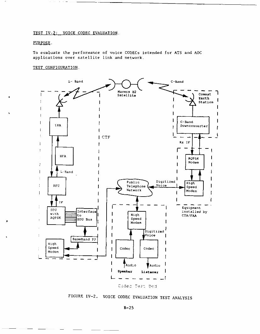
TEST IV-2: VOICE CODEC EVALUATION.
PURPOSE.
To evaluate the performance of voice GODECs intended for ATS and AOGapplications over satellite link and network.
TEST CONFIGURATION.
L- Band j i> §C - and
- -- - karecS B2I satellite i Eat
I Station
C-BandLNA IDownconverter
CTF I_ - - -I
RX IF
HPA QS
L-RandI
Public Digitized HighRFU ITelephone VoiceSpe
I ----------- Equipment
I C ~~ode m oe
SpedCocdec Tez-dec
FIGURE IV- VIECDGEAUTO ETAAYI
t-2
TEST METHOD.
The CTF has a connection to the CODEC Test Bed (CTB) via public telephonenetwork, or leased lines if required, to allow for the transmission ofdigitized voice data over satellite link. The GES will be connected to asecond modem in order to send the downlinked data back to the CTB where it isconverted back to speech by a CODEC.
Various CODECs are evaluated using intelligibility tests, such as theDiagnostic Rhyme Test, modified to determine their suitability for ATScommunications. The tests are conducted under acoustic noise conditions inthe CTB and with actual satellite link delays and degradation.
DATA RECORDED.
Intelligibility test data are recorded for various CODECs under differing
conditions of acoustic noise.
CRITERIA.
The criteria for CODEC intelligibility for ATS applications are currentlyunder development.
REQUIREMENT.
These is no SARPs requirement validated by this test. This test will allowfor the performance evaluation of voice CODECs over actual satellite link andterrestrial network.
B-26
*U.S. GOVERNMENT RINTING OMCE: 1"I - "0"61/40171