ACR-1000 Technical Description Summary ACR-1000 Library/20100100.pdf · 10820-01372-230-002...
57
10820-01372-230-002 2010/01/04 ACR-1000 Technical Description Summary ACR-1000 10820-01372-230-002 Revision 1 2010 January UNRESTRICTED janvier 2010 ILLIMITÉE © Atomic Energy of Canada Limited © Énergie atomique du Canada limitée
Transcript of ACR-1000 Technical Description Summary ACR-1000 Library/20100100.pdf · 10820-01372-230-002...
10820-01372-230-002 2010/01/04
ACR-1000 Technical Description Summary
ACR-1000
10820-01372-230-002 Revision 1
2010 January
UNRESTRICTED
janvier 2010
ILLIMITÉE
© Atomic Energy of Canada Limited
© Énergie atomique du Canada limitée
UNRESTRICTED 10820-01372-230-002 Page i
Rev. 1
10820-01372-230-002 2010/01/04
ACRONYMS
Acronym Full Text/Definition ACR-1000 Advanced CANDU Reactor – 1000 AECL Atomic Energy of Canada Limited ALARA As Low As Reasonably Achievable BOP Balance Of Plant CAMLS CANDU Annunciation Message List System CANDU CANada Deuterium Uranium CNSC Canadian Nuclear Safety Commission DBE Design Basis Earthquake DBT Design Basis Tornado DCS Distributed Control System ECC Emergency Core Cooling EFW Emergency Feedwater FM Fuelling Machine HP High-Pressure (turbine) HSI Human System Interface HTS Heat Transport System IAEA International Atomic Energy Agency I&C Instrumentation and Control LEU Low Enriched Uranium LOCA Loss-of-Coolant Accident LP Low-Pressure (turbine) LTC Long-Term Cooling MACSTOR Modular Air-Cooled Storage MCA Main Control Area MCR Main Control Room MOX Mixed Oxide MSIV Main Steam Isolation Valve MSSV Main Steam Safety Valve NSP Nuclear Steam Plant O&M Operation and Maintenance PAM Post-accident Monitoring PDS Plant Display System PORV Power Operated Relief Valve PSAR Preliminary Safety Analysis Report R&D Research and Development SAGD Steam Assisted Gravity Drainage
UNRESTRICTED 10820-01372-230-002 Page ii
Rev. 1
10820-01372-230-002 2010/01/04
Acronym Full Text/Definition SDS1 Shutdown System No. 1 SDS2 Shutdown System No. 2 SPDS Safety Parameter Display System SSCs Structures, Systems and Components SSMCs Safety System Monitoring Computers UPS Uninterruptible Power Supply VDU Video Display Unit VHL Very Heavy Lift
UNRESTRICTED 10820-01372-230-002 Page iii
Rev. 1
TABLE OF CONTENTS
SECTION PAGE
10820-01372-230-002 2010/01/04
1. INTRODUCTION ............................................................................................1-1
1.1 Historical Basis.................................................................................................1-1 1.2 Features ............................................................................................................1-1 1.3 Safety Philosophy .............................................................................................1-2
2. NUCLEAR SYSTEMS.....................................................................................2-1
2.1 Reactor Assembly.............................................................................................2-2 2.1.1 Reactor Core Design ...................................................................................2-2 2.1.2 Fuel Channel Assembly...............................................................................2-3 2.1.3 Reactor Control...........................................................................................2-4 2.2 Fuel ..................................................................................................................2-4 2.3 Heat Transport and Auxiliary Systems ..............................................................2-5 2.3.1 Heat Transport Pumps.................................................................................2-5 2.3.2 Steam Generators ........................................................................................2-6 2.3.3 Feeder Header Assembly.............................................................................2-6 2.3.4 Pressure and Inventory Control System.......................................................2-6 2.4 Moderator System.............................................................................................2-7 2.5 Fuel Handling System.......................................................................................2-8 2.5.1 New Fuel Transfer and Storage ...................................................................2-8 2.5.2 Fuel Changing.............................................................................................2-8 2.5.3 Spent Fuel Transfer and Storage..................................................................2-8
3. SAFETY CONCEPT ........................................................................................3-1
3.1 Overall Safety Concept and Licensing Approach ..............................................3-1 3.1.1 Defence-in-Depth........................................................................................3-1 3.1.2 Safety and Design Philosophy.....................................................................3-2 3.1.3 Safety Design Criteria .................................................................................3-3 3.1.3.1 Safety System Design Basis ..................................................................3-3 3.1.3.2 Accident Resistance ..............................................................................3-3 3.1.3.3 Core Damage Prevention.......................................................................3-4 3.1.3.4 Accident Mitigation...............................................................................3-4 3.2 Safety and Safety Support Systems ...................................................................3-4 3.2.1 Safety Systems............................................................................................3-4 3.2.2 Safety Support Systems...............................................................................3-6 3.3 Systems/Design Features to Cope with Severe Accidents..................................3-7 3.4 Deterministic and Probabilistic Analyses ..........................................................3-7 3.5 Emergency Planning Measures .........................................................................3-8
4. PROLIFERATION RESISTANCE...................................................................4-1
4.1 Intrinsic Features Contributing to Proliferation Resistance ................................4-1
UNRESTRICTED 10820-01372-230-002 Page iv
Rev. 1
TABLE OF CONTENTS
SECTION PAGE
10820-01372-230-002 2010/01/04
4.2 Extrinsic Features Contributing to Proliferation Resistance ...............................4-1
5. SAFETY AND SECURITY (PHYSICAL PROTECTION) ..............................5-1
5.1 Design Basis Threat and Beyond Design Basis Threat......................................5-1 5.2 Physical Security Requirements ........................................................................5-1 5.3 Nuclear Safety Requirements............................................................................5-2
6. TURBINE GENERATOR SYSTEMS..............................................................6-1
6.1 Turbine Generator Design.................................................................................6-1 6.2 Condensing System...........................................................................................6-1 6.3 Steam and Feedwater Systems ..........................................................................6-2 6.4 Auxiliary Systems.............................................................................................6-2
7. ELECTRICAL AND I&C SYSTEMS ..............................................................7-1
7.1 Electrical Systems.............................................................................................7-1 7.2 Instrumentation and Control Systems................................................................7-1 7.2.1 General .......................................................................................................7-1 7.2.2 Control Centres...........................................................................................7-2 7.2.3 Reactor Protection and Other Safety Systems..............................................7-3
8. SPENT FUEL AND WASTE MANAGEMENT...............................................8-1
8.1 Waste Management...........................................................................................8-1 8.1.1 Solid Radioactive Waste .............................................................................8-1 8.1.2 Liquid Radioactive Waste ...........................................................................8-1 8.1.3 Gaseous Radioactive Waste.........................................................................8-2 8.2 Occupational Dose............................................................................................8-2 8.3 Fuel Utilization .................................................................................................8-2 8.4 Waste Management Costs .................................................................................8-3
9. PLANT LAYOUT ............................................................................................9-1
9.1 Layout Approach ..............................................................................................9-1 9.2 Reactor Building...............................................................................................9-2 9.3 Reactor Auxiliary Building ...............................................................................9-3 9.4 Main Control Building ......................................................................................9-3 9.5 Turbine Building...............................................................................................9-3 9.6 Maintenance Building .......................................................................................9-3 9.7 Service Building ...............................................................................................9-4
10. PLANT PERFORMANCE .............................................................................10-1
10.1 Power Generation Objectives..........................................................................10-1
UNRESTRICTED 10820-01372-230-002 Page v
Rev. 1
TABLE OF CONTENTS
SECTION PAGE
10820-01372-230-002 2010/01/04
10.2 Reliability and Availability Objectives............................................................10-1 10.3 Operation and Maintenance.............................................................................10-2 10.4 Construction ...................................................................................................10-3 10.4.1 Basis for Construction Strategy .................................................................10-3 10.4.2 Prefabrication/Modularization...................................................................10-3 10.4.3 Parallel Construction.................................................................................10-4 10.4.4 Open-Top Construction.............................................................................10-5 10.5 Provision for Low Fuel Reload Costs..............................................................10-5
11. DEVELOPMENT STATUS OF TECHNOLOGIES RELEVANT TO THE ACR-1000..............................................................................................11-1
11.1 Technology in Support of ACR-1000..............................................................11-1 11.2 Technologies Relevant to the ACR-1000 ........................................................11-1
12. DEPLOYMENT STATUS AND PLANNED SCHEDULE ............................12-1
13. REFERENCES ...............................................................................................13-1
TABLES
Table 1-1 Representative CANDU Reactors .....................................................................1-4
FIGURES
Figure 2-1 ACR-1000 Nuclear Systems Schematic ............................................................2-1 Figure 2-2 Reactor Assembly.............................................................................................2-2 Figure 2-3 Fuel Channel Assembly ....................................................................................2-3 Figure 2-4 CANFLEX ACR Fuel Bundle...........................................................................2-4 Figure 2-5 Heat Transport System Layout ..........................................................................2-5 Figure 2-6 ACR-1000 Headers/Upper Feeders Modules.....................................................2-6 Figure 3-1 Shutdown System No. 1 – Shutoff Units ...........................................................3-5 Figure 6-1 Turbine Generator and Auxiliaries Flow Diagram.............................................6-3 Figure 7-1 Control Centre ..................................................................................................7-3 Figure 9-1 ACR-1000 Twin-Unit Power Block ..................................................................9-2 Figure 10-1 Typical Modules of the ACR-1000 Reactor Building ......................................10-4
APPENDICES
Appendix A Summarized Technical Data (HWR) ................................................................A-1
UNRESTRICTED 10820-01372-230-002 Page 1-1
Rev. 1
10820-01372-230-002 2010/01/04
1. INTRODUCTION
The Advanced CANDU Reactor-1000 (ACR-1000®1) design is Atomic Energy of Canada Limited’s (AECL) evolutionary, Gen III+, 1200 MWe class pressure tube reactor. It meets the industry and public expectations for safe, reliable, environmentally friendly, low-cost nuclear power generation. It has been designed to be licensable internationally by ensuring its compliance with Canadian nuclear regulations and the fundamental safety objectives of the International Atomic Energy Agency (IAEA) safety standard.
The ACR-1000 is a light water cooled, heavy water moderated pressure tube reactor, using low enriched uranium (LEU) fuel with on-power fuelling.
1.1 Historical Basis
AECL has established a successful, internationally recognized line of CANDU®2 pressure tube reactors that use a heavy water moderator, in particular, the medium-sized CANDU 6 reactor. AECL has consistently adopted an evolutionary approach to the enhancement of CANDU nuclear power plant designs over the last 30 years.
The ACR-1000 design has evolved from AECL’s in-depth knowledge of CANDU structures, systems, components (SSCs) and materials, as well as from the experience and feedback received from operating CANDU plants. The ACR-1000 features major improvements in economics, inherent safety characteristics, and performance, while retaining the proven benefits of the CANDU family of nuclear power plants.
The CANDU system is ideally suited to this evolutionary design approach since the modular fuel channel reactor design can be modified extensively, through a series of incremental changes in the reactor core design, to adjust the power output and improve the overall safety, economics, and performance. A summary of the CANDU plants in-service is provided in Table 1-1.
1.2 Features
The ACR-1000 design retains many essential features of the CANDU plant design, including horizontal fuel channel core, a low temperature heavy-water moderator, a water filled reactor vault, two independent safety shutdown systems, a highly automated control system, on-power fuelling and a Reactor Building that is accessible for on-power maintenance and testing. It is designed with a focus on operations and maintenance (O&M), drawing on AECL’s experience in the design, construction and operation of existing CANDU plants for utilities around the world, as well as on valuable customer input.
The following key differences from the traditional CANDU design are incorporated into the design of the ACR-1000:
1 ACR-1000® (Advanced CANDU Reactor ®) is a registered trademark of Atomic Energy of Canada Limited
(AECL). 2 CANDU® (CANada Deuterium Uranium®) is a registered trademark of Atomic Energy of Canada Limited
(AECL).
UNRESTRICTED 10820-01372-230-002 Page 1-2
Rev. 1
10820-01372-230-002 2010/01/04
The use of LEU fuel contained in CANFLEX®3-ACR fuel bundles.
The use of light water instead of heavy water as the reactor coolant.
Lower moderator volume to fuel ratio.
These features together with a number of other evolutionary changes lead to the following benefits for the ACR-1000 design:
A more compact core design, which further reduces heavy water inventory.
An increased burn-up as a result of the fuel enrichment.
Increased safety margins (e.g., improved critical heat flux performance).
Improved overall turbine cycle efficiency through the use of higher pressures and higher temperatures in the coolant and steam supply systems.
Reduced emissions, through the elimination of tritium production in the coolant and other environmental protection improvements.
Enhanced severe accident management by providing backup heat sinks.
Improved performance through the use of advanced operational and maintenance information systems.
Improved separation of redundant SSCs important to safety through the use of a four quadrant plant layout.
These advancements as well as improvements to project engineering, manufacturing, and construction technologies, including the use of state-of-the-art tools, result in significantly reduced capital cost and construction schedules while enhancing the inherent safety of the ACR-1000 design.
1.3 Safety Philosophy
The ACR-1000 plant is designed based on the “defence-in-depth” safety philosophy applied to all CANDU plants with enhancements to further improve the overall safety of the plant. This includes the core design incorporating a negative power coefficient of reactivity, improved performance of safety systems, a robust containment design to meet Canadian and international practice for new nuclear power plants, and ensuring a measure of inherent safety by incorporating a set of reactivity coefficients that result in a self-limiting reactivity transient even in the event of a large loss-of-coolant accident (LOCA) in which the shutdown systems do not operate.
The design approach for the ACR-1000 plant ensures safety during construction, commissioning, start-up, and O&M by assuring the following:
Ample thermal and safety margins for safe operation.
Collective radiation exposure to plant personnel and the public is well below regulatory limits.
Feedback from construction, commissioning, start-up, and O&M is incorporated.
The “defence-in-depth” safety philosophy is applied.
3 CANFLEX® is a registered trademark of Atomic Energy of Canada Limited (AECL).
UNRESTRICTED 10820-01372-230-002 Page 1-3
Rev. 1
10820-01372-230-002 2010/01/04
Physical and functional separation of safety systems.
Simplified, more reliable systems.
Safety systems perform their required safety functions during design basis accidents without credit for active mitigation by the process systems.
Human factors engineering principles and criteria are applied in the design of systems, facilities, equipment, and procedures.
Compliance with applicable government regulations related to environmental protection.
Security and robustness of the plant against malevolent acts and external events.
Severe accidents are considered in the plant design.
UNRESTRICTED 10820-01372-230-002 Page 1-4
Rev. 1
10820-01372-230-002 2010/01/04
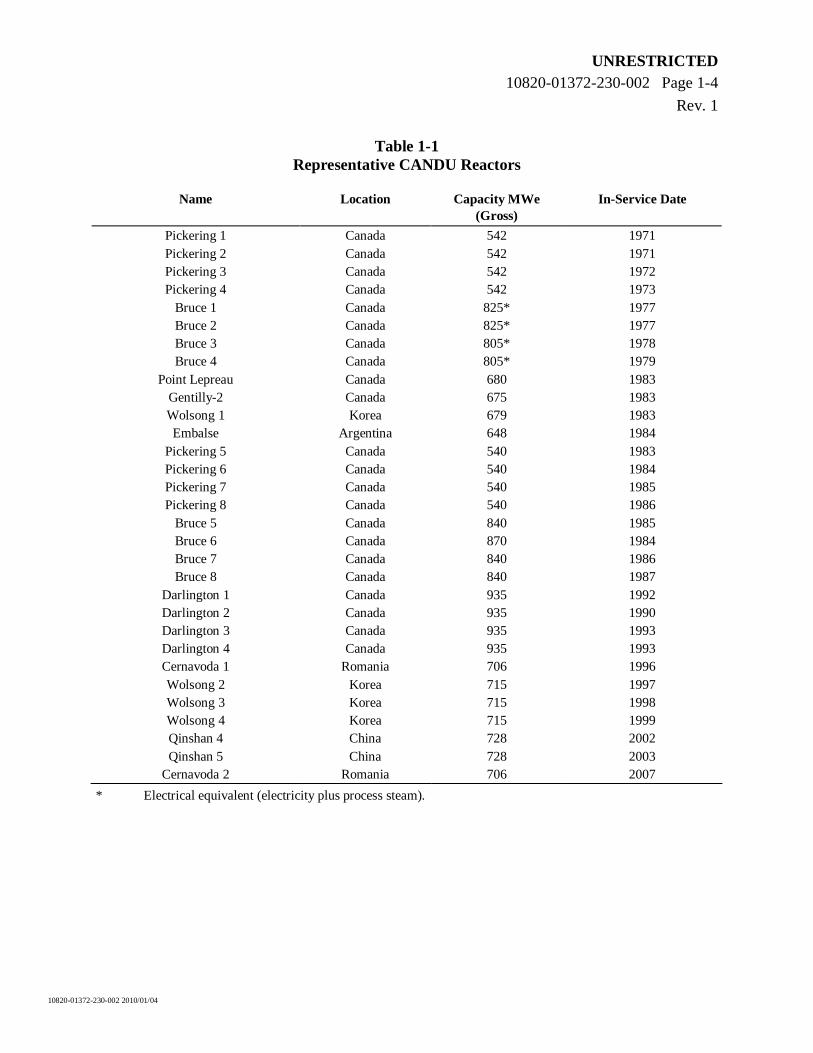
Table 1-1 Representative CANDU Reactors
Name Location Capacity MWe (Gross)
In-Service Date
Pickering 1 Canada 542 1971 Pickering 2 Canada 542 1971 Pickering 3 Canada 542 1972 Pickering 4 Canada 542 1973
Bruce 1 Canada 825* 1977 Bruce 2 Canada 825* 1977 Bruce 3 Canada 805* 1978 Bruce 4 Canada 805* 1979
Point Lepreau Canada 680 1983 Gentilly-2 Canada 675 1983 Wolsong 1 Korea 679 1983 Embalse Argentina 648 1984
Pickering 5 Canada 540 1983 Pickering 6 Canada 540 1984 Pickering 7 Canada 540 1985 Pickering 8 Canada 540 1986
Bruce 5 Canada 840 1985 Bruce 6 Canada 870 1984 Bruce 7 Canada 840 1986 Bruce 8 Canada 840 1987
Darlington 1 Canada 935 1992 Darlington 2 Canada 935 1990 Darlington 3 Canada 935 1993 Darlington 4 Canada 935 1993 Cernavoda 1 Romania 706 1996 Wolsong 2 Korea 715 1997 Wolsong 3 Korea 715 1998 Wolsong 4 Korea 715 1999 Qinshan 4 China 728 2002 Qinshan 5 China 728 2003
Cernavoda 2 Romania 706 2007
* Electrical equivalent (electricity plus process steam).
UNRESTRICTED 10820-01372-230-002 Page 2-1
Rev. 1
10820-01372-230-002 2010/01/04
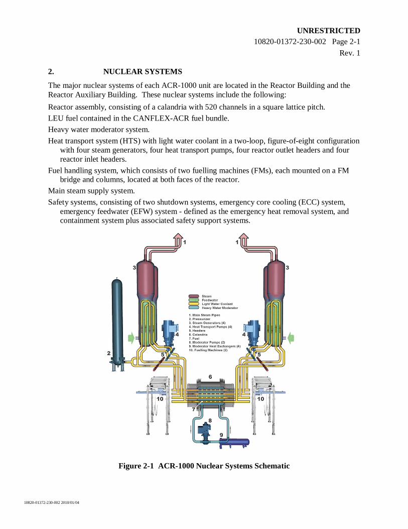
2. NUCLEAR SYSTEMS
The major nuclear systems of each ACR-1000 unit are located in the Reactor Building and the Reactor Auxiliary Building. These nuclear systems include the following:
Reactor assembly, consisting of a calandria with 520 channels in a square lattice pitch.
LEU fuel contained in the CANFLEX-ACR fuel bundle.
Heavy water moderator system.
Heat transport system (HTS) with light water coolant in a two-loop, figure-of-eight configuration with four steam generators, four heat transport pumps, four reactor outlet headers and four reactor inlet headers.
Fuel handling system, which consists of two fuelling machines (FMs), each mounted on a FM bridge and columns, located at both faces of the reactor.
Main steam supply system.
Safety systems, consisting of two shutdown systems, emergency core cooling (ECC) system, emergency feedwater (EFW) system - defined as the emergency heat removal system, and containment system plus associated safety support systems.
Figure 2-1 ACR-1000 Nuclear Systems Schematic
UNRESTRICTED 10820-01372-230-002 Page 2-2
Rev. 1
10820-01372-230-002 2010/01/04
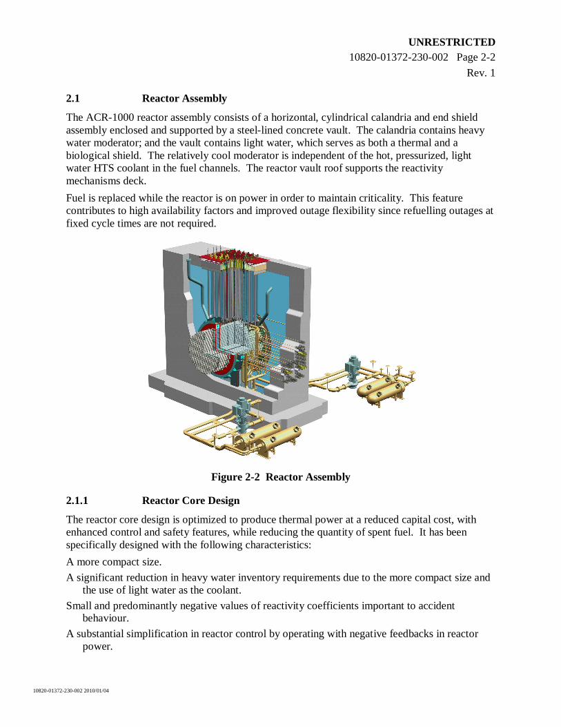
2.1 Reactor Assembly
The ACR-1000 reactor assembly consists of a horizontal, cylindrical calandria and end shield assembly enclosed and supported by a steel-lined concrete vault. The calandria contains heavy water moderator; and the vault contains light water, which serves as both a thermal and a biological shield. The relatively cool moderator is independent of the hot, pressurized, light water HTS coolant in the fuel channels. The reactor vault roof supports the reactivity mechanisms deck.
Fuel is replaced while the reactor is on power in order to maintain criticality. This feature contributes to high availability factors and improved outage flexibility since refuelling outages at fixed cycle times are not required.
Figure 2-2 Reactor Assembly
2.1.1 Reactor Core Design
The reactor core design is optimized to produce thermal power at a reduced capital cost, with enhanced control and safety features, while reducing the quantity of spent fuel. It has been specifically designed with the following characteristics:
A more compact size.
A significant reduction in heavy water inventory requirements due to the more compact size and the use of light water as the coolant.
Small and predominantly negative values of reactivity coefficients important to accident behaviour.
A substantial simplification in reactor control by operating with negative feedbacks in reactor power.
UNRESTRICTED 10820-01372-230-002 Page 2-3
Rev. 1
10820-01372-230-002 2010/01/04
An increase in the reliability and effectiveness of the ECC system due to the simplified interface with the HTS since they both use light water.
A flat, radial flux profile enables the reactor to operate at a very high radial power form factor. The axial power shape is also relatively flat. This shape results naturally from the characteristics of the core, coupled with the bidirectional fuelling scheme, and acts to reduce the capital costs by minimizing the size of the core relative to its power output.
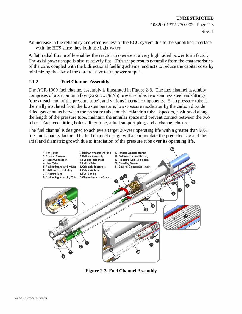
2.1.2 Fuel Channel Assembly
The ACR-1000 fuel channel assembly is illustrated in Figure 2-3. The fuel channel assembly comprises of a zirconium alloy (Zr-2.5wt% Nb) pressure tube, two stainless steel end-fittings (one at each end of the pressure tube), and various internal components. Each pressure tube is thermally insulated from the low-temperature, low-pressure moderator by the carbon dioxide filled gas annulus between the pressure tube and the calandria tube. Spacers, positioned along the length of the pressure tube, maintain the annular space and prevent contact between the two tubes. Each end-fitting holds a liner tube, a fuel support plug, and a channel closure.
The fuel channel is designed to achieve a target 30-year operating life with a greater than 90% lifetime capacity factor. The fuel channel design will accommodate the predicted sag and the axial and diametric growth due to irradiation of the pressure tube over its operating life.
Figure 2-3 Fuel Channel Assembly

UNRESTRICTED 10820-01372-230-002 Page 2-4
Rev. 1
10820-01372-230-002 2010/01/04
2.1.3 Reactor Control
The primary reactivity control elements in the ACR-1000 design are the mechanical zone control units. Each unit is divided into two independently movable absorber elements. Day-to-day reactivity control is performed by on-power refuelling and zone control action.
The reactor regulating system also includes mechanical control absorber units that can be used if larger power reductions are required. Control absorber rods can either be inserted slowly under motor control or dropped into the core by gravity.
All reactivity mechanisms operate in the water filled reactor vault or the low-temperature, low-pressure moderator environment and are simple, rugged, highly reliable, and require little maintenance.
2.2 Fuel
The 43-element CANFLEX-ACR fuel bundle is used for the ACR-1000, shown in Figure 2-4. The outer three rings of fuel elements contain enriched uranium pellets while the central fuel element contains burnable neutron absorber in a stabilized zirconia matrix. A small amount of burnable poison is incorporated into the LEU fuel elements for control of initial reactivity. A thin layer of CANLUB (graphite coating) covers the inside surface of the fuel element sheaths to enhance the fuel elements’ ability to withstand power ramp.
The fuel sheath, endcaps, endplates and appendages are made of Zircaloy-4 for its nuclear characteristics of low neutron absorption, good corrosion resistance, and low hydrogen pickup.
Figure 2-4 CANFLEX ACR Fuel Bundle
The same fuel bundle design is used for all stages of the life of the core, from the initial start-up core to the reference equilibrium core. The level of enrichment of the uranium dioxide in the fuel pellets for the start-up core is lower than that for the reference fuel. With a much higher operating margin for initial years of reactor operation, the amount of burnable neutron absorber in the central element can be reduced to achieve an increase in the exit burnup.
Major features include the use of enriched uranium and neutron absorbers (dysprosium and gadolinium) in a zirconium oxide matrix in the centre element, and uniform diameter of all elements except the centre element.
UNRESTRICTED 10820-01372-230-002 Page 2-5
Rev. 1
10820-01372-230-002 2010/01/04
One of the many advantages of the ACR-1000 design is its unique capability to efficiently burn a variety of fuel cycles including thorium and mixed oxide (MOX). This will enhance economics, extend nuclear fuel resources and assure energy security well into the future, while reducing waste and enhancing proliferation resistance.
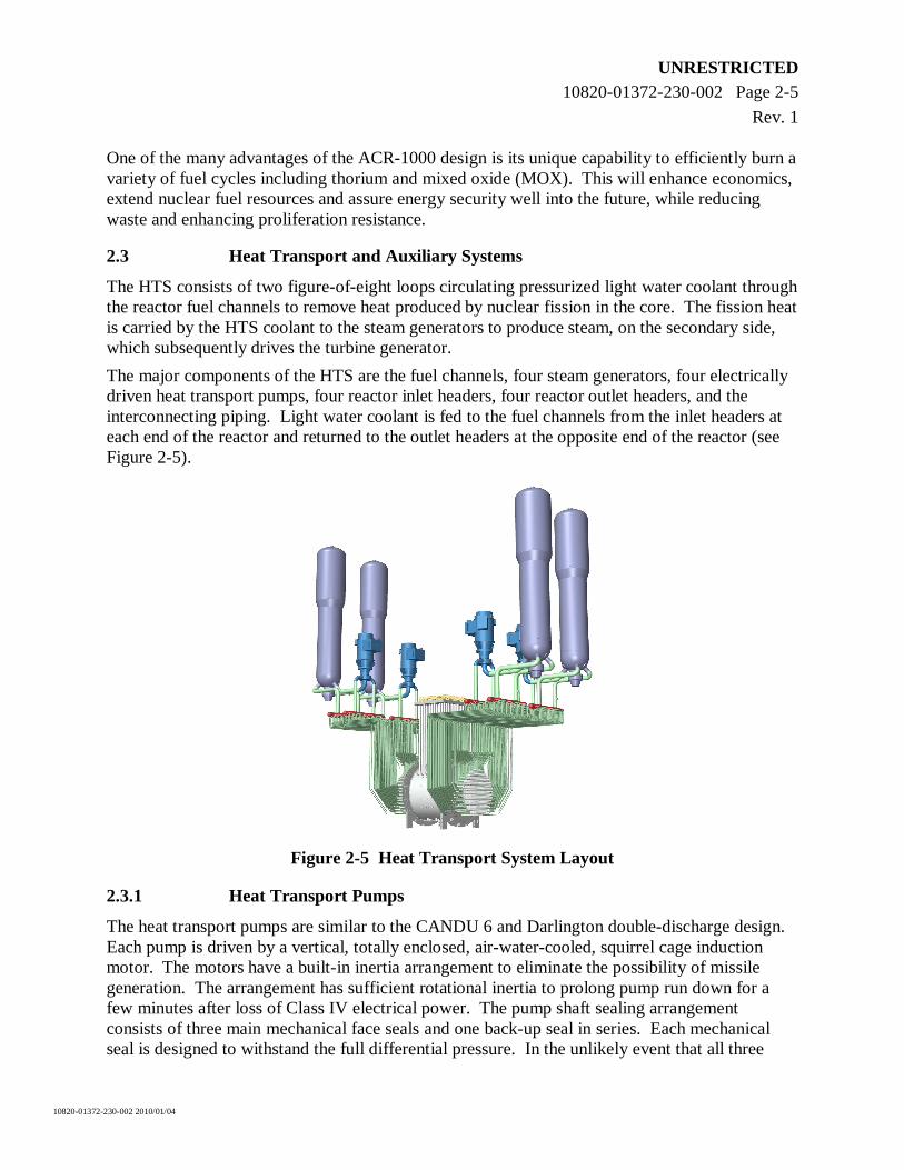
2.3 Heat Transport and Auxiliary Systems
The HTS consists of two figure-of-eight loops circulating pressurized light water coolant through the reactor fuel channels to remove heat produced by nuclear fission in the core. The fission heat is carried by the HTS coolant to the steam generators to produce steam, on the secondary side, which subsequently drives the turbine generator.
The major components of the HTS are the fuel channels, four steam generators, four electrically driven heat transport pumps, four reactor inlet headers, four reactor outlet headers, and the interconnecting piping. Light water coolant is fed to the fuel channels from the inlet headers at each end of the reactor and returned to the outlet headers at the opposite end of the reactor (see Figure 2-5).
Figure 2-5 Heat Transport System Layout
2.3.1 Heat Transport Pumps
The heat transport pumps are similar to the CANDU 6 and Darlington double-discharge design. Each pump is driven by a vertical, totally enclosed, air-water-cooled, squirrel cage induction motor. The motors have a built-in inertia arrangement to eliminate the possibility of missile generation. The arrangement has sufficient rotational inertia to prolong pump run down for a few minutes after loss of Class IV electrical power. The pump shaft sealing arrangement consists of three main mechanical face seals and one back-up seal in series. Each mechanical seal is designed to withstand the full differential pressure. In the unlikely event that all three
UNRESTRICTED 10820-01372-230-002 Page 2-6
Rev. 1
10820-01372-230-002 2010/01/04
main seals fail, the back-up seal prevents significant leakage of coolant to containment during depressurization of the HTS. The three mechanical seals and back-up seal are constructed as a single seal package assembly in a removable cartridge for easy replacement.
2.3.2 Steam Generators
The ACR-1000 steam generators are similar in design to CANDU 6, except for an increased tube diameter and a larger overall physical size. The steam generators transfer heat from the light water coolant on the primary side of the steam generator to raise the temperature of, and boil, feedwater on the secondary side to produce steam. Each steam generator consists of an inverted, vertical U-tube bundle installed in a cylindrical shell, and an integrated preheater section. Each is connected to supply headers for emergency feedwater and reserve water systems. Steam-separating equipment is provided in the steam drum in the upper part of the shell. The four steam generators are designed to maintain both primary and secondary pressure boundaries and heat sink requirements during a design basis earthquake (DBE).
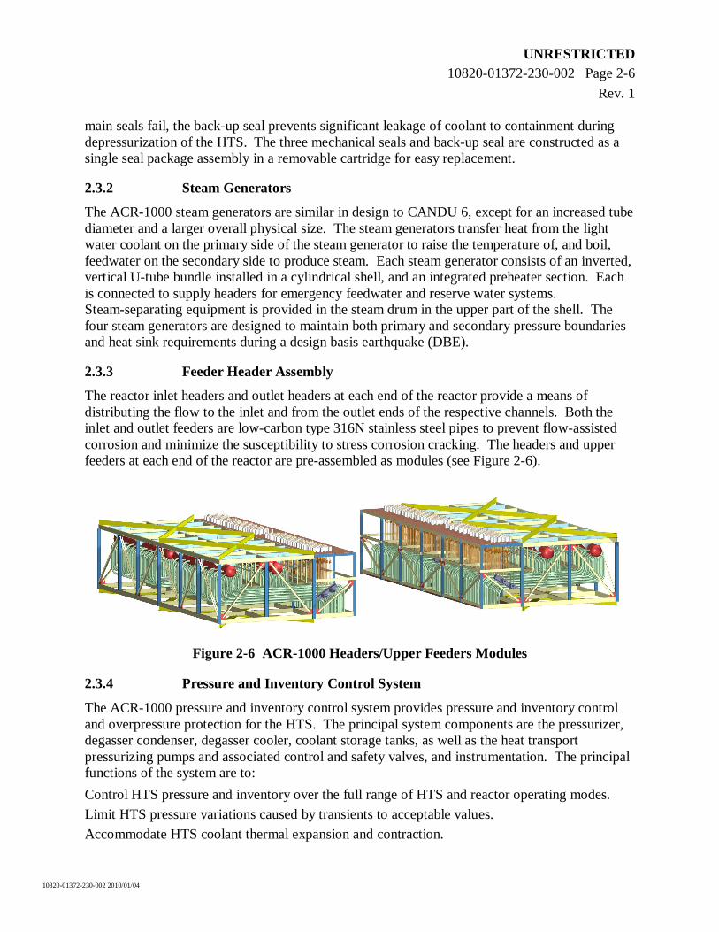
2.3.3 Feeder Header Assembly
The reactor inlet headers and outlet headers at each end of the reactor provide a means of distributing the flow to the inlet and from the outlet ends of the respective channels. Both the inlet and outlet feeders are low-carbon type 316N stainless steel pipes to prevent flow-assisted corrosion and minimize the susceptibility to stress corrosion cracking. The headers and upper feeders at each end of the reactor are pre-assembled as modules (see Figure 2-6).
Figure 2-6 ACR-1000 Headers/Upper Feeders Modules
2.3.4 Pressure and Inventory Control System
The ACR-1000 pressure and inventory control system provides pressure and inventory control and overpressure protection for the HTS. The principal system components are the pressurizer, degasser condenser, degasser cooler, coolant storage tanks, as well as the heat transport pressurizing pumps and associated control and safety valves, and instrumentation. The principal functions of the system are to:
Control HTS pressure and inventory over the full range of HTS and reactor operating modes.
Limit HTS pressure variations caused by transients to acceptable values.
Accommodate HTS coolant thermal expansion and contraction.
UNRESTRICTED 10820-01372-230-002 Page 2-7
Rev. 1
10820-01372-230-002 2010/01/04
Provide degassing of the HTS coolant.
The major components of this system are described below:
The pressurizer is connected to the HTS via one of the two reactor outlet headers in each loop. Flow to and from the heat transport purification system provides pressure control and inventory make-up to the HTS during reactor transients. Spray flow and heaters provide pressure control.
The degasser condenser acts as a receiver for relief flow from the HTS, acts as a receiver and condenser for steam relief from the pressurizer, and is used as a means of degassing the HTS. The degasser condenser pressure is controlled using a cooling spray flow and electrical heaters.
The degasser cooler heat exchanger cools the water flow at the bottom nozzle of the degasser condenser and returns it to the pressurizing pump suction.
Pressurizing pumps provide water make-up to the HTS during normal operation and upset conditions.
The coolant storage tank provides inventory to accommodate the swell and shrinkage for the HTS as required.
Liquid relief valves provide overpressure protection to the HTS by discharging the coolant to the degasser condenser.
2.4 Moderator System
The moderator system is a low-pressure and low-temperature system. The system maintains the structural integrity of the calandria assembly by removing the heat generated in the heavy water by neutron moderation, and the heat transferred to the heavy water from the calandria structures. The heavy water also serves as a neutron reflector and a medium for dispersing neutron poisons for rapid reactor shutdown.
The moderator system consists of pumps and heat exchangers that circulate heavy water moderator through the calandria vessel. During normal operation, the heavy water moderator is drawn from the calandria via four outlet ports located near the top of the calandria vessel. The heavy water is circulated by one moderator pump and through four heat exchangers to remove the moderator heat load. The flow returns to the calandria via twelve inlet nozzles located just beneath the outlet ports.
The locations of the inlet and outlet nozzles on the calandria vessel are optimized to ensure uniform moderator temperature distribution throughout the reactor.
The moderator system is also connected to the reserve water system, which provides back-up water (light water) to the calandria vessel following a loss of moderator during a severe accident. In addition, the moderator system interfaces with other auxiliary systems to purify the heavy water, remove radiolytic deuterium and oxygen, maintain heavy water inventory, and to disperse chemicals for reactivity and chemistry control.
UNRESTRICTED 10820-01372-230-002 Page 2-8
Rev. 1
10820-01372-230-002 2010/01/04
2.5 Fuel Handling System
The function of the fuel handling system is to refuel the reactor on demand for the purpose of controlling the reactor power distribution and excess reactivity. The fuel handling system stores and handles fuel, from the arrival of new fuel to the storage of spent fuel. The fuel handling system is divided into new fuel transfer and storage, fuel changing, and spent fuel transfer and storage.
2.5.1 New Fuel Transfer and Storage
The new fuel transfer and storage system supplies the FMs with sufficient fuel to maintain full-power operation. Since refuelling is normally performed on-power, new fuel is stored, inspected, and loaded from an accessible area in the Reactor Auxiliary Building.
2.5.2 Fuel Changing
Refuelling is done remotely using two FMs, one at each reactor face. The two most downstream fuel bundles are discharged into one FM while two new fuel bundles are inserted at the upstream end by the other FM.
A bridge and carriage system allows the FM to traverse the entire reactor face for access to all fuel channels. The system also allows the FM access to the service port and the new and spent fuel transfer ports.
2.5.3 Spent Fuel Transfer and Storage
The spent fuel transfer and storage system handles spent fuel from the time it is discharged from the FM to the time it is removed from the spent fuel bay.
Once the FM discharges spent fuel into the transfer tube, the transfer system uses recirculating water to push fuel through the pipe to the transfer mechanism located in the spent fuel receiving bays. The water in the pipe also serves to cool the fuel during transit. The transfer mechanism then unloads the fuel from its magazine into a mechanism that places the fuel into storage baskets.
The storage bay provides storage of spent fuel for typically 10 years of operation.
Spent fuel from the receiving bay is moved to the storage bay through a shielded tunnel that connects the two bays. Within the storage bay, the spent fuel storage baskets are stacked in storage frames. The baskets are suitable for direct transfer to the longer-term dry (spent) fuel storage. Equipment, such as the storage bay bridge and handling tools, is provided to permit manipulation of spent fuel and containers.
UNRESTRICTED 10820-01372-230-002 Page 3-1
Rev. 1
10820-01372-230-002 2010/01/04
3. SAFETY CONCEPT
3.1 Overall Safety Concept and Licensing Approach
The objectives of safety design are to:
Take all reasonably practicable measures to prevent accidents in the nuclear power plant and to mitigate their consequences should they occur;
Ensure with a high level of confidence that, for all postulated accidents considered in the design including those of very low probability, radiological consequences would be below prescribed limits;
Ensure that the likelihood of accidents with serious radiological consequences is extremely low.
To ensure that the ACR-1000 design is licensable in Canada and to facilitate its licensability in other countries, the following licensing requirements have been applied:
The design complies with relevant Canadian nuclear safety requirements.
The design meets the IAEA requirements as specified in the IAEA Safety Standards Series No. NS-R-1, “Safety of Nuclear Power Plants: Design - Safety Requirements” (Reference [1]).
The design meets the environmental requirements for siting in Canada.
In addition, the ACR-1000 design has taken into consideration requirements from other jurisdictions and can accommodate them with limited changes to the reference design.
3.1.1 Defence-in-Depth
The concept of defence-in-depth is applied throughout the ACR-1000 plant design to provide a series of levels of defence, including measures to prevent accidents and measures to provide protection in the event that prevention fails. Consistent with the overall safety concept of defence-in-depth, the design of the ACR-1000 plant aims to prevent, as far as practicable, challenges to the integrity of physical barriers; failure of a barrier when challenged, and failure of a barrier as a consequence of the failure of another barrier. This approach is structured in five levels, as presented below:
Level 1 – Prevention of abnormal operation and of failures of SSCs by conservative design and high quality in construction.
Level 2 – Detection and control of deviations from normal operation by controlling plant behaviour with both inherent and engineered design features.
Level 3 – Control of accidents within the design basis by provision of inherent safety features, fail safe design, engineered design features, and procedures.
Level 4 – Control of severe plant conditions to manage accidents and mitigate their consequences, as far as practicable, by the robust containment design, complementary design features, and severe accident management procedures.
Level 5 – Mitigation of radiological consequences of significant releases of radioactive materials by emergency support centre and plans for on-site and off-site emergency response.
In particular, four plant states are defined to be consistent with the first four levels of defence: normal operation, anticipated operational occurrences, design basis accidents which include
UNRESTRICTED 10820-01372-230-002 Page 3-2
Rev. 1
10820-01372-230-002 2010/01/04
external events, and beyond design basis accidents. Probabilistic acceptance criteria are defined for each plant state.
3.1.2 Safety and Design Philosophy
There are four fundamental safety functions that must be performed by plant systems to assure public safety, following an accident. These are as follows:
Control of reactivity (control)
Removal of heat from the core (cool)
Confinement of radioactive materials and control of operational discharges, as well as limitation of accidental releases (contain), and
Monitoring of critical safety parameters to guide operator actions (monitor).
Where practical, or as required to satisfy reliability targets, SSCs that perform the same safety function are of different design.
Diversity may also be needed to achieve the necessary protection against certain types of common-cause events (e.g., software errors, manufacturing errors, maintenance errors, etc.), and is directly related to a need for increased reliability after redundancy and separation have been provided.
The “Four Quadrant Separation Philosophy” is applied to the ACR-1000 design to achieve independence of systems important to safety. Four quadrants in the Reactor Auxiliary Building are separated by barriers that provide protection against common cause events. Redundant equipment and divisions of the safety systems, safety support systems, and other systems important to safety are located in these quadrants. The principles of physical and functional separation are applied to prevent common cause events from causing the loss of any safety function.
Separation between systems is provided to ensure that the plant safety functions continue to remain available in the presence of a hazard caused by a common cause event. Separation and independence also include the provision of a secondary control area for each unit as a back-up to the Main Control Room (MCR) for certain emergency conditions.
Safety systems and safety support systems are seismically qualified to remain functional during and following a DBE.
The ACR-1000 design utilizes passive, stored-energy, natural circulation and gravity features for:
Reactor shutdown,
Cooling of the HTS when forced circulation is unavailable,
Core refill and fuel cooling following a LOCA,
Post-accident pressure and temperature suppression inside containment,
Emergency feedwater supply to the steam generators, and
Mitigation of postulated beyond design basis accidents.
UNRESTRICTED 10820-01372-230-002 Page 3-3
Rev. 1
10820-01372-230-002 2010/01/04
The design also provides integration of human factors engineering principles, standards, requirements, and processes throughout all system design stages.
3.1.3 Safety Design Criteria
Robust design has been achieved through implementation of inherent design features and engineered systems as discussed in the following subsections.
3.1.3.1 Safety System Design Basis
The ACR-1000 maintains the cornerstone of traditional CANDU safety system design in having two fully capable, redundant and diverse fast acting shutdown systems. For any given design basis accident, either of these shutdown systems acting alone is completely effective in ensuring that the plant response is within the safety acceptance criteria.
The design requirements for the safety systems include, but are not limited to, the following:
Redundancy in safety equipment and clear procedures (to ensure single failure criterion is met).
Fail-safe operation where practical.
Separation and independence from each other and from process systems, to the extent practical, with a limited sharing of sensors between process and some safety systems.
High reliability of system actuation on demand as well as during system operation.
Seismic qualification.
Environmental qualification.
Protection against impact and dynamic loads.
3.1.3.2 Accident Resistance
Design features reduce the probability and severity of accidents. The design minimizes the occurrence and propagation of initiating events that could lead to events of greater severity and resulting challenges to safety systems by the following:
Sufficient margin is designed into the plant.
The DBE is selected to envelope the site conditions.
The reactor design incorporates a negative power coefficient of reactivity.
The small coolant void reactivity offers a balance of inherent nuclear protection between LOCA and accidents with fast cooldown of the HTS. This results in much reduced integrated energy in the fuel and a reduced peak clad temperature after a large LOCA.
A human system interface (HSI) designed to minimize operator error and optimize human performance during normal operation through quick and accurate diagnosis of off-normal conditions.
Control systems are capable of handling most anticipated operational occurrences and some design basis accidents without the need for safety systems (e.g., setbacks, stepbacks, and self-checking).
UNRESTRICTED 10820-01372-230-002 Page 3-4
Rev. 1
10820-01372-230-002 2010/01/04
3.1.3.3 Core Damage Prevention
In the event that accident prevention measures are not sufficient, engineered systems are provided to prevent significant damage to the reactor core as follows:
Independent safety systems are provided for the key functions of reactor shutdown, core decay heat removal and containment of radioactive releases.
Two diverse shutdown systems, independent from each other and the reactor regulating system, are provided.
The safety system responses are automated to the extent that no operator action is needed for a minimum of eight hours.
Each unit can withstand loss of off-site electrical power and loss of one set of diesels4 for at least 24 hours without fuel damage.
3.1.3.4 Accident Mitigation
An accident may progress to the release of radioactive material from the fuel. To prevent the release of these materials to the public and the environment, the ACR-1000 design:
Provides a robust containment building and associated systems for heat removal and retention of radionuclides for all design basis events. The containment design pressure is based on the limiting design basis event.
Provides a containment system with a design leak rate of no more than 0.2% by volume per day at design pressure.
Provides a hydrogen control system so that the concentrations of combustible hydrogen under design basis events and limited core damage accidents do not exceed the hydrogen detonation limits commensurate with the probability and severity of the event.
Incorporates design features that protect against common mode events such as earthquakes, fires, and flooding.
3.2 Safety and Safety Support Systems
3.2.1 Safety Systems
Each unit has dedicated safety systems, which are systems designed to shut down the reactor, remove decay heat, and limit the radioactivity release subsequent to the failure of normally operating process systems. The five safety systems are as follows:
Shutdown System No. 1
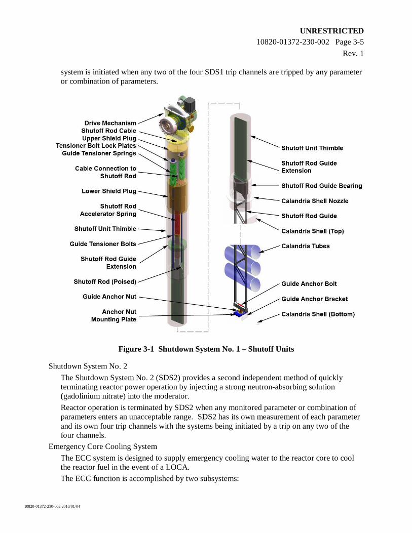
The Shutdown System No. 1 (SDS1) quickly terminates reactor power operation and brings the reactor into a safe shutdown condition by dropping shutoff rods, shown in Figure 3-1, into the low pressure moderator.
Reactor operation is terminated when a certain neutronic or process parameter enters an unacceptable range. The measurement of each parameter is performed by channel, and the
4 Defined as one set of essential diesels per unit or one set of common plant diesels.
UNRESTRICTED 10820-01372-230-002 Page 3-5
Rev. 1
10820-01372-230-002 2010/01/04
system is initiated when any two of the four SDS1 trip channels are tripped by any parameter or combination of parameters.
Figure 3-1 Shutdown System No. 1 – Shutoff Units
Shutdown System No. 2
The Shutdown System No. 2 (SDS2) provides a second independent method of quickly terminating reactor power operation by injecting a strong neutron-absorbing solution (gadolinium nitrate) into the moderator.
Reactor operation is terminated by SDS2 when any monitored parameter or combination of parameters enters an unacceptable range. SDS2 has its own measurement of each parameter and its own four trip channels with the systems being initiated by a trip on any two of the four channels.
Emergency Core Cooling System
The ECC system is designed to supply emergency cooling water to the reactor core to cool the reactor fuel in the event of a LOCA.
The ECC function is accomplished by two subsystems:
UNRESTRICTED 10820-01372-230-002 Page 3-6
Rev. 1
10820-01372-230-002 2010/01/04
The emergency coolant injection system, which injects high-pressure coolant into the HTS after a LOCA.
The long-term cooling (LTC) system provides long-term injection including coolant recovery after a LOCA. The LTC system is also used for long-term cooling after reactor shutdown following non-LOCA accidents, and during normal shutdown operation to allow for routine maintenance activities.
Emergency Feedwater System
The emergency heat removal function is accomplished by the EFW system. This system is designed to provide cooling water to the secondary side of the steam generators to enable them to transfer the decay heat to the ultimate heat sink when a loss of normal feedwater supply (main feedwater and start-up feedwater) is detected. The EFW system is designed to meet regulatory requirements for an emergency heat removal system.
Containment System
The basic function of the containment system is to provide a continuous, pressure-retaining envelope around the reactor core and HTS. Following an accident, the containment system minimizes release of resultant radioactive materials to the external environment to below regulatory limits.
The containment system includes the steel-lined, pre-stressed concrete Reactor Building containment structure, main and auxiliary airlocks, containment cooling spray for pressure suppression, and a containment isolation system consisting of valves in certain process lines or dampers in the ventilation ducts penetrating the containment envelope. The containment design ensures a low leakage rate while at the same time providing a pressure-retaining boundary for all design basis accidents causing high pressure and/or temperature inside containment.
The containment system automatically closes all penetrations open to the Reactor Building atmosphere when an increase in containment pressure or radioactivity level is detected. Instrumentation for measurements of containment pressure and radioactivity are quadruplicated and the system is actuated using two-out-of-four logic.
3.2.2 Safety Support Systems
Each unit also has dedicated safety support systems which are those that provide services needed for proper operation of the safety systems (e.g., electrical power, cooling water, and instrument air). For the ACR-1000 design, major safety support systems include the following:
Reserve water system – A seismically qualified reserve water tank, which is located at a high elevation in the Reactor Building, provides a passive emergency source of water automatically by gravity to the steam generators, containment cooling spray, calandria vessel, reactor vault, and HTS, if required.
Electrical power systems – Supplies all electrical power needed to perform safety functions under transient and accident conditions and non-safety functions for normal operation. The safety support portions of the systems are seismically qualified and consist of redundant divisions of standby generators, batteries, and distribution to the safety loads.
UNRESTRICTED 10820-01372-230-002 Page 3-7
Rev. 1
10820-01372-230-002 2010/01/04
Essential cooling water system – Provides demineralized cooling water to systems important to safety.
Essential service water system – Disposes of the heat from the essential cooling water system to the ultimate heat sink.
Compressed air system – Provides service air, instrument air, and breathing air to different safety systems and power production systems in the plant.
Chilled water system – Supplies water to air conditioning and miscellaneous equipment and provides sufficient cooling capacity during normal operation.
3.3 Systems/Design Features to Cope with Severe Accidents
In the ACR-1000 design, severe core damage mitigation provisions include the following systems and design features:
Shield cooling system.
Large thermal capacity of heavy water in the moderator and light water in the reactor vault.
Passive make-up to the reactor vault from the reserve water tank, including make-up from external sources.
Strong (robust) Reactor Building structure with steel liner and with large free volume.
Containment local air coolers.
Passive containment cooling spray.
Hydrogen control (passive recombiners and igniters).
Reserve water tank water recovery by the LTC system.
The majority of these features are passive. These design features provide high confidence if severe core damage occurs, it will not lead to the failure of the calandria vessel or the containment.
3.4 Deterministic and Probabilistic Analyses
The safety of an ACR-1000 power plant is demonstrated by performing an analysis of unplanned events/accidents. Accidents must be shown to have acceptable consequences, not only if normally operating systems and safety systems work, but also if a safety system is unavailable or impaired. Both deterministic and probabilistic analyses are conducted to ensure that the safety systems are designed to satisfy appropriate targets for performance and reliability.
Deterministic analyses, using conservative assumptions, are performed for design basis events to demonstrate compliance with specified acceptance criteria, including limits for radiological dose to the public. Deterministic analyses, using realistic assumptions and detailed models, are also performed for limited core damage accidents to demonstrate compliance with the specified performance targets, including limits for radiological dose to the public. Probabilistic analyses are performed to demonstrate the achievability of targets for prevention and mitigation of severe accidents. A Level 2 probabilistic safety assessment includes analysis of core damage progression and containment response for severe accidents.
UNRESTRICTED 10820-01372-230-002 Page 3-8
Rev. 1
10820-01372-230-002 2010/01/04
The severe core damage frequency is 9.5 x 10⁻⁸ and 8.7 x 10⁻⁸ per reactor year at-power internal events and shutdown event respectively. Fire and flood events are not expected to be dominant contributors. The results show that the ACR-1000 summed severe core damage frequency is more than an order of magnitude less than the RD-337 requirement of 1 x 10⁻⁵ per reactor year.
Summed frequency for the sequences resulting in large releases from the plant is between 8 x10⁻⁸
and 8 x 10⁻⁹ per reactor year which is more than an order of magnitude less than the RD-337 requirement of 1 x 10⁻⁶ per reactor year.
The seismic margin assessment shows a plant high confidence of low probability of failure of at least 0.5g indicating a robust design for seismic events.
3.5 Emergency Planning Measures
The fifth and final level of defence-in-depth requires the mitigation of radiological releases resulting from accident conditions with the provision of an emergency support centre and plans for on-site and off-site emergency response.
To fulfill this requirement, the ACR-1000 design provides:
An operational support centre located in close proximity to the MCR where operations support personnel assemble in an emergency. It has dedicated voice communication facilities to the technical support centre and MCR and capability for on-site and off-site communication.
A technical support centre, which is used as an assembly area for plant management and technical support to the operating personnel located in the MCR during emergency conditions. The technical support centre is equipped with the following:
Workstations with plant display system (PDS) and safety system monitoring computers (SSMCs) displays to ensure plant-wide data (including radiological conditions in the plant and immediate surroundings and meteorological conditions in the vicinity of the plant) can be monitored and evaluated independent from the actions occurring in the MCR.
Adequate space for communication facilities for on-site and off-site communication.
Storage space for emergency plans, procedures, protective clothing, drawings, and cabinets housing equipment for first aid.
A second technical support centre, located on-site, outside the protected area in a separate building will be provided, if required, to address local regulations or utility requirements. This will be used as a back-up in the event the primary centre is uninhabitable or not functional.
UNRESTRICTED 10820-01372-230-002 Page 4-1
Rev. 1
10820-01372-230-002 2010/01/04
4. PROLIFERATION RESISTANCE
Provisions are made in the design of the ACR-1000 plant for the installation of safeguard systems. The supply and installation of safeguard instrumentation is the responsibility of the IAEA through its agreements with the utility. The provisions made for this equipment are based on the installation of systems similar to the ones that have been previously accepted by the IAEA on the CANDU 6 plants, with support for increased remote monitoring and real time accounting. The anticipated instrumentation for safeguard purposes includes spent fuel bundle counters, surveillance cameras, and other devices. The use of sealable, dry storage ready spent fuel baskets allows for a considerable simplification of the application of safeguards.
4.1 Intrinsic Features Contributing to Proliferation Resistance
The ACR-1000 design has intrinsic features that minimize the attractiveness of CANDU technology as a target for proliferation. In the ACR-1000 design, on-load refuelling is a continuous operation, necessary in order to maintain criticality and regional safety margins in a reactor core that has little excess reactivity. Remotely controlled and fully automated fuelling machines perform all refuelling operations; the reactor cannot be refuelled manually.
The inherently low excess reactivity of the CANDU core, the design of the fuelling machines to maintain steady core power under these restrictive conditions, and the requirement to fully characterize the core flux distribution on a continuous basis, combine to discourage misuse of the core for the purposes of weapons-grade material production.
4.2 Extrinsic Features Contributing to Proliferation Resistance
The CANDU safeguards system consists of installed IAEA technology for surveillance and item accountancy verification. These are reviewed either through IAEA inspections or through remote monitoring supplemented by unannounced inspections. The remotely operated and highly automated fuel handling process in CANDU reactors makes automated monitoring of individual fuel bundle movement a highly reliable and straightforward exercise. It is possible to track every CANDU fuel bundle throughout its life cycle, as well as detecting with high probability any undeclared irradiation and movement of fuel bundles.
UNRESTRICTED 10820-01372-230-002 Page 5-1
Rev. 1
10820-01372-230-002 2010/01/04
5. SAFETY AND SECURITY (PHYSICAL PROTECTION)
The protection of the plant against sabotage and malevolent acts or threats is provided through the principle of defence-in-depth. This includes the physical protection system, engineered safety provisions, and measures for post-event management.
5.1 Design Basis Threat and Beyond Design Basis Threat
The ACR-1000 plant resists a set of threats that are categorized as design basis threats and beyond design basis threats. Threats identified as design basis threats have credible attributes and characteristics of potential insider or external adversaries who might attempt sabotage against which a physical protection system is designed and evaluated. Beyond design basis threats are less frequent and more severe than design basis threats and their consequences are assessed in order to establish means of mitigation to the extent practicable.
Three types of threats are considered during the life of the plant:
1. National design basis threats: The definition of these threats is the responsibility of the regulator. The national design basis threat definition is based on threat risk assessment and is reviewed periodically, per applicable regulations, and can change during the life of the plant.
2. Project-specific threats: These threats are considered in the design of the facility and can be categorized as design basis threats and beyond design basis threats.
3. Site-specific threats: These threats can vary from plant to plant based on the actual site and plant characteristics.
5.2 Physical Security Requirements
The physical security requirements for the ACR-1000 plant are as follows:
Nuclear material, systems, and equipment that are important to safety and the sabotage of which could lead to unacceptable radiological consequences, are located within the vital area(s).
Access and number of access points to the protected area(s) and the vital area(s) are kept to a minimum. All emergency exits are fitted with intrusion detection sensors. Other points of potential access are secured and alarmed.
The design and construction of vital areas provide penetration delay. Vital areas are secured and alarms set when unattended.
A series of independent physical barriers are provided consistent with the defence-in-depth principle.
The protected area is provided with a robust physical barrier. Intrusion detection is provided at the physical barrier. Clear areas are provided on both sides of the perimeter of the protected area with illumination sufficient for assessment.
A continuously staffed and hardened security monitoring room is provided.
All intrusion detection sensors annunciate in the security monitoring room.
Dedicated and tamper indicating transmission systems and power supplies (from uninterruptible emergency power) are provided for and between the security monitoring room and the intrusion detection systems.
UNRESTRICTED 10820-01372-230-002 Page 5-2
Rev. 1
10820-01372-230-002 2010/01/04
Dedicated and diverse transmission systems for two-way communication between the security monitoring room and the response force are provided.
5.3 Nuclear Safety Requirements
The goal of these requirements is to ensure the safe shutdown of the reactor and the removal of decay heat until the security event is stabilized and mitigation can be carried out. The overall safety requirements for the ACR-1000 plant from a security point of view are as follows:
The nuclear facility is shown to be sufficiently robust to prevent uncontrolled release of fission products outside of containment (i.e., no catastrophic failure of containment).
In the event of radioactive release, the dose is below prescribed limits.
Systems required for shutdown, cooling, and monitoring of the reactor, continue to be available as required.
Operation of systems important to safety is possible in the event of attack or sabotage, given the related adverse conditions such as fire, smoke, and structural damage, until mitigation can be effected.
For the spent fuel handling and storage systems, adequate heat removal is provided.
Acceptance criteria for SSCs important to safety for the design basis threat category are based on conservative assumptions such as design margins, redundancy, diversity, and hypothetical extreme events.
Acceptance criteria for survival capabilities of SSCs important to safety, as well as operator actions and functioning of emergency plans and procedures, for the beyond design basis threat category are based on design centred assumptions (i.e., best estimate).
Given that threats may come from inside as well as outside the plant, the design considers placement of civil utilities, including sewers, manholes, and service tunnels to reduce access requirements for repair, maintenance, etc., to promote security from all threats.
UNRESTRICTED 10820-01372-230-002 Page 6-1
Rev. 1
10820-01372-230-002 2010/01/04
6. TURBINE GENERATOR SYSTEMS
Four steam generators located in the Reactor Building are designed to remove heat from the HTS and deliver steam to the turbine generator via the main steam system to generate electrical power.
The turbine generator system and the condensate and feedwater systems are based on conventional designs. They meet the design requirements specified to assure the performance and integrity of the nuclear steam plant (NSP). These include material requirements, chemistry control requirements, feedwater train reliability requirements, feedwater inventory requirements, and turbine bypass capability.
Site differences affect the condenser cooling water design temperature, which in turn affects the turbine exhaust conditions, condenser pressure, and the electrical power output.
6.1 Turbine Generator Design
The turbine generator is an 1800-rpm, impulse-type, tandem compound, reheat condensing-type with one double-flow, high-pressure (HP) section and three double-flow, low-pressure (LP) sections. It is designed to operate in both base load and alternate modes of operation, either reactor leading or turbine leading. Steam from the main steam system enters the HP turbine through four stop valves and four governing control valves. Cross-ties are provided both upstream and downstream of the stop valves to provide pressure equalization with one or more stop valves closed. A portion of the main steam is used for second-stage reheat of the steam supply to the LP turbines. There are two steam extraction points in the HP turbine. Steam from the first extraction point (from HP turbine) is used for first-stage reheat of the two-stage reheater. Steam from the second extraction point is used for sixth-stage feedwater heating.
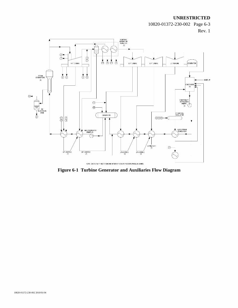
In addition, there are two external (two-stage) moisture separator reheaters in parallel to remove moisture from and to reheat the HP turbine exhaust steam. Figure 6-1 shows the flow diagram for the turbine generator and auxiliaries.
6.2 Condensing System
After expansion in the LP turbines, the steam is condensed in the main condenser by heat transferred to the condenser cooling water system. The condensate from the main condenser is deaerated and returned to the steam generators via regenerative feedwater heating.
The condenser cooling water system supplies once-through cooling water to the main condenser. This system pumps cooling water through the main condenser in order to condense the turbine exhaust steam and to maintain rated back-pressure conditions at the turbine exhaust. The system components and materials minimize deterioration of the heat transfer capability of the condenser under normal operating conditions and ensure a high degree of availability.
The extraction steam system supplies the six stages of the regenerative feedwater heating (Figure 6-1). The LP feedwater heating system consists of double banks of the LP feedwater heaters, and a deaerator. The HP system consists of double banks of two HP feedwater heaters. The deaerator is normally heated with extraction steam from the turbine. At plant start-up, the heating steam to the deaerator is fed from the auxiliary steam header or the main steam line.
UNRESTRICTED 10820-01372-230-002 Page 6-2
Rev. 1
10820-01372-230-002 2010/01/04
The condensate system includes two 100% capacity, electrically driven condensate pumps and an electrically driven auxiliary condensate pump with back-up power from the balance of plant (BOP) standby diesel generators.
A turbine bypass system can discharge steam directly to the main condenser when the turbine or the grid is unavailable in order to prevent a reactor poison out.
6.3 Steam and Feedwater Systems
The steam and feedwater system is composed of the main steam lines and the feedwater supply to the steam generators.
Main steam is generated in the four steam generators located in the Reactor Building and supplied to the turbine generator and auxiliary steam systems. Steam lines from each steam generator supply steam to a main steam (balance) header located in the Turbine Building. The main steam safety valves (MSSVs), the power operated relief valves (PORVs) and the main steam isolation valves (MSIVs) are located on the steam lines upstream of the main steam header. One MSIV is installed on each steam line downstream of the MSSVs and PORV to isolate the steam generators from the main steam balance header for certain postulated accident scenarios. The MSIVs are each powered by supplies from the essential Class II power system. Separate steam lines are routed from the main steam header in the Turbine Building to the HP turbine steam chest via the turbine stop valves.
The feedwater system includes three motor driven main feedwater pumps and one electrically driven start-up feedwater pump with back-up power from the BOP standby diesel generators.
6.4 Auxiliary Systems
The turbine generator system is provided with other necessary auxiliary systems, including the following:
Sampling system: Permits condensate and feedwater samples to be taken for chemical analysis.
Steam drain system: Recovers heat and treated water (condensate) from the various equipment drains.
Chemical injection system: Used to add chemicals to the condensate and feedwater systems to maintain and control the chemistry within the specified ranges.
UNRESTRICTED 10820-01372-230-002 Page 6-3
Rev. 1
10820-01372-230-002 2010/01/04
Figure 6-1 Turbine Generator and Auxiliaries Flow Diagram
UNRESTRICTED 10820-01372-230-002 Page 7-1
Rev. 1
10820-01372-230-002 2010/01/04
7. ELECTRICAL AND I&C SYSTEMS
7.1 Electrical Systems
The electrical power system consists of connections to the off-site grid, the main turbine generator and the associated main output system, the on-site standby diesel generators, battery power supplies, uninterruptible power supplies (UPSs), and distribution equipment.
The system is equipped with the necessary protection, controls, and monitoring to enable it to supply electrical energy output to the grid and to all loads within the power plant. Equipment distributing power from the essential standby diesel generators, batteries, and the UPSs to the NSP in each unit is seismically and environmentally qualified. Each unit of the ACR-1000 plant has a dedicated electrical distribution system with inter-unit ties in the non-safety Class III distribution and common plant diesel generators. The preferred sources of power to the electrical power distribution system are the off-site network during reactor start-up and shutdown, and the main turbine generator, shared with the off-site network, during all other normal operating conditions.
The essential power distribution system is divided into four physically separate and electrically independent divisions supplying power to equipment in safety and safety support systems. Each division includes a dedicated essential standby generator and a UPS.
The electrical distribution system is divided into four classes of power based on availability:
Class IV – Used for production-related loads in the plant. Long-term interruption can be tolerated without endangering equipment, personnel, or plant safety.
Class III – Receives power from the grid/turbine generator with back-up from on-site standby diesel generators. The essential NSP Class III distribution and on-site generation are seismically qualified.
Class II – Uninterruptible power except during transfers between Class I and Class III supply and during fault conditions. The essential NSP Class II is seismically qualified.
Class I – Uninterruptible power except during fault conditions. The essential Class I is seismically qualified.
7.2 Instrumentation and Control Systems
7.2.1 General
The ACR-1000 plant uses highly automated control systems which have evolved from previous CANDU designs. Building from this base, the ACR-1000 design benefits from the application of modern distributed control, display, and network communication technologies. The key benefits of the improved instrumentation and control (I&C) systems are:
Reduction in the number of I&C components, leading to improved reliability and reduced maintenance and construction costs.
Increased automation to free the operations staff from tedious or stressful tasks, thus reducing the frequency of operator error.
UNRESTRICTED 10820-01372-230-002 Page 7-2
Rev. 1
10820-01372-230-002 2010/01/04
Improved information and data communications systems that facilitate awareness of the unit operational state, providing better detection and diagnosis of faults, and reducing plant outages.
7.2.2 Control Centres
The ACR-1000 control centres provide the facilities and environment for the operating staff to monitor, control, and operate the unit(s) in both normal and abnormal modes. The control centres include the main control area (MCA) and the secondary control area. The MCA is a facility that serves two generating units. The MCA layout can accommodate shared or separated MCRs and consists of the following:
The MCR which includes unitized consoles and unitized/common panels for the two units. The MCR provides the man-machine interfaces required to operate the plant safely and efficiently under normal conditions and maintain it in a safe manner under accident conditions, except for events that disable the MCR itself.
A technical support centre, which is used as an assembly area for plant management and technical support to the operating personnel located in the MCR during emergency conditions.
An operational support centre where operations support personnel assemble in an emergency.
A work control area, outage management area, office space for administration personnel, and a security desk for access control to the MCR.
The secondary control area provides sufficient display and control instrumentation to allow the plant to be shut down and maintained in a safe shutdown condition if the MCR becomes uninhabitable or not functional.
Most control functions are performed by a modern distributed control system (DCS), which uses numerous programmable digital controller modules rather than a single large computer. The controllers communicate with one another by means of data highways, which use reliable, high-security data transmission methods. Manual control commands to be executed by the DCS are entered by the operators via the PDS.
In addition to the control functions, the DCS also provides data acquisition for the monitoring, alarm annunciation, display, and data recording functions performed by the PDS and for most of the post-accident monitoring (PAM)/safety parameter display system (SPDS) functionality implemented in the SSMCs. High reliability is achieved by providing dual redundancy for all the important components with comprehensive fault detection and automatic switchover in case of faults.
The PDS is the primary operator interface in the MCR and provides a real-time and historical display, and advanced alarm annunciation features, based on the CANDU annunciation message list system (CAMLS) designed to assist in unit operations. It consists of a collection of HSI stations comprised of video display unit (VDU) device(s), operator input device(s) and hard copy devices.
UNRESTRICTED 10820-01372-230-002 Page 7-3
Rev. 1
10820-01372-230-002 2010/01/04
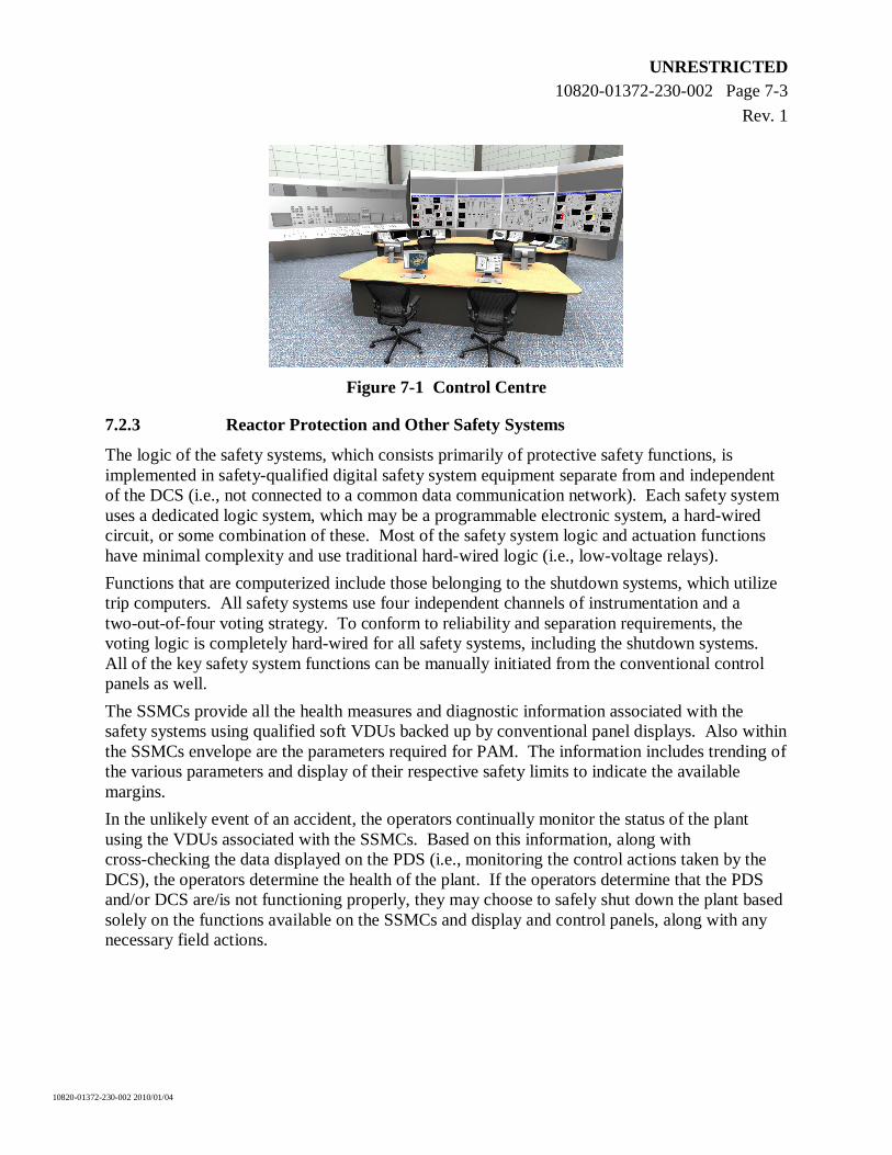
Figure 7-1 Control Centre
7.2.3 Reactor Protection and Other Safety Systems
The logic of the safety systems, which consists primarily of protective safety functions, is implemented in safety-qualified digital safety system equipment separate from and independent of the DCS (i.e., not connected to a common data communication network). Each safety system uses a dedicated logic system, which may be a programmable electronic system, a hard-wired circuit, or some combination of these. Most of the safety system logic and actuation functions have minimal complexity and use traditional hard-wired logic (i.e., low-voltage relays).
Functions that are computerized include those belonging to the shutdown systems, which utilize trip computers. All safety systems use four independent channels of instrumentation and a two-out-of-four voting strategy. To conform to reliability and separation requirements, the voting logic is completely hard-wired for all safety systems, including the shutdown systems. All of the key safety system functions can be manually initiated from the conventional control panels as well.
The SSMCs provide all the health measures and diagnostic information associated with the safety systems using qualified soft VDUs backed up by conventional panel displays. Also within the SSMCs envelope are the parameters required for PAM. The information includes trending of the various parameters and display of their respective safety limits to indicate the available margins.
In the unlikely event of an accident, the operators continually monitor the status of the plant using the VDUs associated with the SSMCs. Based on this information, along with cross-checking the data displayed on the PDS (i.e., monitoring the control actions taken by the DCS), the operators determine the health of the plant. If the operators determine that the PDS and/or DCS are/is not functioning properly, they may choose to safely shut down the plant based solely on the functions available on the SSMCs and display and control panels, along with any necessary field actions.
UNRESTRICTED 10820-01372-230-002 Page 8-1
Rev. 1
10820-01372-230-002 2010/01/04
8. SPENT FUEL AND WASTE MANAGEMENT
The ACR-1000 design incorporates provisions to reduce waste and dose limits, increase fuel utilization, and reduce waste management costs.
8.1 Waste Management
The integrated two-unit plant utilizes as much as practicable, common waste management systems and facilities. The waste management systems are designed such that the radiological exposure of operating staff and the public is minimized and is well within the limits recommended by Canadian Nuclear Safety Commission (CNSC) regulatory document RD-337 (Reference [2]) and radiation protection regulations. The radioactive waste management systems provide for the collection, storage, treatment, and dispersal of all radioactive solid, liquid, and gaseous wastes generated in the plant.
Radionuclides remain predominately at their place of origin but may be transported to, and ultimately reach, one or more parts of the radioactive waste management systems. Thus, for example, fuel fission products that may escape from fuel defects while in the core or in the fuel handling equipment are filtered, trapped, or removed in the HTS and its auxiliary systems. This leads to the disposal of the majority of the fission products in spent resin or filter elements as solid wastes, which are contained within the Reactor Building. Radionuclides that escape from the HTS boundary reach the Reactor Building atmosphere. They are collected in the active ventilation ducts and caught in the Reactor Building exhaust filters and released under control in the gaseous radioactive waste management system or, if deposited and washed down, they reach the liquid radioactive waste facilities through the active drainage system.
8.1.1 Solid Radioactive Waste
Solid radioactive wastes can be classified by five main groups: spent fuel, spent resins, spent filter cartridges, compactable, and non-compactable activity solid waste. Each type of waste is processed differently. Spent fuel is initially stored in the spent fuel bay and eventually transferred to on-site dry storage. The other wastes are collected after processing and prepared for on-site storage by the utility or for transport off-site. The final disposal methods depend on the particular site, regulatory requirements, and policies of the utility.
8.1.2 Liquid Radioactive Waste
The liquid radioactive waste management system includes improved segregation of the liquid effluent consisting of six liquid waste storage tanks (two detergents, two low-activity and two active). A treatment circuit is provided to treat the liquid waste before discharge. The effluent is monitored by the liquid effluent monitor prior to discharge to ensure operating targets (which are well below regulatory limits) are not exceeded. Organic fluids, oils and chemicals can be treated by decontamination, solidification or incineration, and can be prepared for on-site storage by the utility or for transport off-site.
UNRESTRICTED 10820-01372-230-002 Page 8-2
Rev. 1
10820-01372-230-002 2010/01/04
8.1.3 Gaseous Radioactive Waste
All active or potentially radioactive gases, vapours, or airborne particulates that occur in the plant are monitored and filtered prior to release into the atmosphere.
The vapour recovery system reduces tritium-in-air concentration in gaseous effluents, and the off-gas management system reduces the radioactivity in radioactive noble gases by delay in an adsorber bed (Xenon and Krypton) or in a delay tank (Argon-41).
All active or potentially active gases, vapours, or airborne particulates that occur in the plant are monitored, treated and filtered by the active ventilation systems prior to release to the atmosphere. The effluent is monitored to ensure that release limits are not exceeded.
Tritium releases from the atmospherically-sealed moderator areas are collected by the vapour recovery system and stored at site. Removal of the heavy water vapour reduces worker exposure to tritium and lowers tritium emissions from the plant as a whole.
8.2 Occupational Dose
Operating CANDU plants have an excellent record of achieving very low occupational doses for operations staff. The ACR-1000 design incorporates design improvements to further reduce radiation exposures to as low as reasonably achievable (ALARA). Design provisions include:
Use of LEU fuel and a reduced lattice pitch. This reduces the thermal neutron flux and hence the activation within the moderator.
Use of light water coolant in the ACR-1000 with depleted LiOH for chemistry control which significantly reduces the production of tritium in the HTS.
Having two major radiological zones. This reduces the time taken to enter and exit the facility, particularly during reactor shutdown, and makes it easier to control contamination as compared to the CANDU 6 three-zone approach. In addition, fewer monitoring stations at zone boundaries are needed; leading to reduced manpower needs and reduced collective doses.
Use of stainless steel for the HTS feeders reduces flow-assisted corrosion and therefore reduces the quantity of mobile material available for activation and the requirement for feeder-thinning inspections.
Use of underwater spent fuel transfer. This ensures less off-gassing of radioiodines and noble gases during handling of depleted fuel.
Use of nitrogen cover gas in the FM to prevent air ingress to the HTS coolant during refuelling operations, thereby lowering the production of Argon-41.
8.3 Fuel Utilization
The ACR-1000 design optimizes fuel utilization by maintaining the traditional CANDU core design focus on neutron economy consistent with the ACR-1000 specific evolutionary design characteristics. For example, the ACR-1000 uses low absorption structural materials and does not require poison in the moderator to manage reactivity since the ACR-1000 is fuelled on-power.
UNRESTRICTED 10820-01372-230-002 Page 8-3
Rev. 1
10820-01372-230-002 2010/01/04
8.4 Waste Management Costs
Provisions incorporated in the ACR-1000 design to reduce waste management costs include:
CANFLEX-ACR fuel bundle – The bundle conforms to a uniform CANDU bundle geometry (~10-cm diameter and ~50-cm length) which allows the bundles to be easily handled and stored thereby reducing operating costs.
Spent fuel baskets – Unlike previous CANDUs, the ACR-1000 spent fuel baskets in the spent fuel bay are suitable for both wet and dry storage. Also, there are no additional costs associated with transferring the spent fuel bundles to separate dry storage baskets.
Dry storage – The MACSTOR (Modular Air-Cooled Storage) dry storage facility is a concrete structure which uses passive air circulation to cool the spent fuel bundles. This facility is essentially maintenance free, which reduces any costs associated with ongoing maintenance.
UNRESTRICTED 10820-01372-230-002 Page 9-1
Rev. 1
10820-01372-230-002 2010/01/04
9. PLANT LAYOUT
The plant layout developed for the ACR-1000 design is based on past experience of CANDU sites with single, two, and four-unit arrangements. Based on the feedback from operating CANDU plants and recent site evaluations, the optimum layout from design, capital cost, construction and O&M considerations is an integrated two-unit ACR-1000 plant arrangement. The major buildings and structures associated with the overall site arrangement are as follows:
Reactor Building (2).
Reactor Auxiliary Building (2).
Turbine Building (2).
Crane Hall (2).
Main Control Building.
Service Building.
Maintenance Building.
Plant service water & condenser cooling water pumphouse.
Essential service water pumphouse.
Diesel generator buildings (a total of five buildings, of which four have safety support functions).
Main switchyard.
Water treatment facility.
Auxiliary and ancillary structures.
The main structures of each unit define the basic power block of the unit, which consists of the Reactor Building, the Reactor Auxiliary Building, the Crane Hall, and the Turbine Building.
The area between the two units is dedicated to common services and facilities to support the operation of the plant. The individual units of the two-unit plant share control, maintenance, administration, service areas and some common process systems. The buildings comprising the shared area are the Maintenance Building, Main Control Building, and Service Building.
9.1 Layout Approach
The layout of the buildings is arranged to minimize the footprint and achieve a short practical construction schedule. This is achieved by simplifying the layout, optimizing interfaces, reducing construction congestion, providing improved access to all areas, and reducing material handling requirements.
The layout approach is to house all safety systems in buildings which are qualified for DBE and design basis tornado (DBT). Accordingly, the Reactor Building and the Reactor Auxiliary Building house all the nuclear systems, safety systems, and the majority of the safety support systems. The MSSVs and MSIVs are located in an enclosure on the roof of the Reactor Auxiliary Building. The safety support systems are located in the Reactor Auxiliary Building, the essential service water pumphouse, and the Main Control Building. Through physical plant separation, the plant layout minimizes the potential for common cause events that could impact redundant components and divisions at the same time. The layout also ensures that either one or both of the units can be safely shut down when required.
Based on the redundancy and separation approach adopted for the ACR-1000 plant, safety systems are located in four physically separated areas called quadrants. The MCR, located in the DBE qualified Main Control Building, is a shared room housing unit dedicated control centers for each unit. A seismically qualified route is provided for the operator to move from the MCR
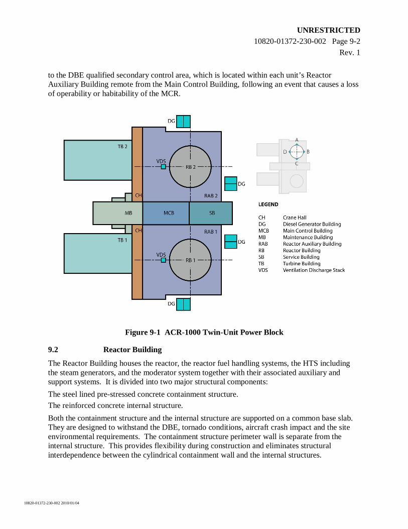
UNRESTRICTED 10820-01372-230-002 Page 9-2
Rev. 1
10820-01372-230-002 2010/01/04
to the DBE qualified secondary control area, which is located within each unit’s Reactor Auxiliary Building remote from the Main Control Building, following an event that causes a loss of operability or habitability of the MCR.
Figure 9-1 ACR-1000 Twin-Unit Power Block
9.2 Reactor Building
The Reactor Building houses the reactor, the reactor fuel handling systems, the HTS including the steam generators, and the moderator system together with their associated auxiliary and support systems. It is divided into two major structural components:
The steel lined pre-stressed concrete containment structure.
The reinforced concrete internal structure.
Both the containment structure and the internal structure are supported on a common base slab. They are designed to withstand the DBE, tornado conditions, aircraft crash impact and the site environmental requirements. The containment structure perimeter wall is separate from the internal structure. This provides flexibility during construction and eliminates structural interdependence between the cylindrical containment wall and the internal structures.
UNRESTRICTED 10820-01372-230-002 Page 9-3
Rev. 1
10820-01372-230-002 2010/01/04
The containment structure provides an environmental boundary, biological shielding, and a pressure boundary in the event of an accident.
The major internal structures include the reactor vault walls, the FM vault walls, the steam generator enclosure, the heat transport pump support floors, the reactivity mechanism floor, and the intermediate floors and are constructed using reinforced concrete. These walls and floors are designed to support all imposed loads and arranged to integrate process equipment spaces with shielding. Minor internal structures include steel floors and steel frames providing equipment support, crane runway support, pipe restraints, walkways, and stairs. The layout of the internal structure walls, floors, active equipment, and components is arranged to minimize personnel exposure to radiation while maximizing on-power access for testing and maintenance of components, and to allow modularization in order to minimize construction costs and schedule.
9.3 Reactor Auxiliary Building
The Reactor Auxiliary Building is a multi-storey, reinforced concrete structure seismically qualified to DBE, tornado protected and is designed for aircraft crash impact. It surrounds the Reactor Building and accommodates the umbilicals, which run between the principal structures, the safety support systems, the electrical systems, and the spent fuel bay and associated fuel handling facilities. The safety and isolation valves of the main steam lines are housed in a seismically and tornado qualified enclosure located on top of the Reactor Auxiliary Building.
The overall arrangement of the Reactor Auxiliary Building supports four divisions of safety support systems in a quadrant layout. Each quadrant houses instrumentation and cable penetration interface with the Reactor Building, one division of the LTC system, essential cooling water system, EFW system, control equipment and electrical gear, and building ventilation and services important to safety. It also houses the secondary control area, spent fuel bay and associated cooling and purification system.
9.4 Main Control Building
The Main Control Building is a multi-storey structure located between the two units and consists of a reinforced concrete substructure and a reinforced concrete/steel frame superstructure. It contains a shared MCR and associated control equipment for the two units. The building structure is qualified for both DBE and DBT.
9.5 Turbine Building
The Turbine Building houses the turbine generator and its auxiliary systems, the main condenser, the condensate and feedwater systems, and any compressed gas required for the balance of plant. It is oriented such that the turbine shaft alignment is perpendicular to the Reactor Building, thus assuring that any turbine-generated missiles would not affect containment, the MCR, or areas vital to safety.
9.6 Maintenance Building
The Maintenance Building is a multi-storey structure consisting of a reinforced concrete substructure and a braced steel frame superstructure and includes a crane hall. It is seismically
UNRESTRICTED 10820-01372-230-002 Page 9-4
Rev. 1
10820-01372-230-002 2010/01/04
qualified for DBE. Also, the basement is a concrete structure that houses heavy water storage tanks. The building is tornado protected to the extent that it prevents damage to the storage tanks.
The Maintenance Building houses facilities and shared services for maintenance and operation of the two-unit plant. The crane hall acts as an internal traffic route and a buffer between the major buildings (see Figure 9-1). The crane hall is seismically qualified to the extent that it does not collapse, affecting SSCs important to safety.
9.7 Service Building
The Service Building is a conventional multi-storey structure consisting of a reinforced concrete substructure and superstructure. It is seismically qualified to the extent that it does not collapse causing damage to the MCB and the Reactor Auxiliary Building.
The two-unit Service Building (which is dedicated to two units) houses and supports maintenance and administrative services and facilities that are not accommodated in the Maintenance Buildings. These facilities and services include conventional plant services (such as mechanical maintenance and storage areas, change rooms, and lunch rooms) and administration services (such as reception area and clerical facilities).
UNRESTRICTED 10820-01372-230-002 Page 10-1
Rev. 1
10820-01372-230-002 2010/01/04
10. PLANT PERFORMANCE
The plant design is centred on the following key principles, while retaining the proven benefits of the CANDU family of nuclear power plants:
Enhanced safety, which has been obtained by more inherent characteristics, as well as more reliable engineered systems relative to current plants.
Enhanced economics, which have been achieved through measures to reduce capital cost, as well as lower maintenance and operation costs due to improved performance and reliability of components.
Enhanced sustainability, which has been accomplished by the selective use and conservation of resources and the reduction of waste, both radioactive and non-radioactive.
10.1 Power Generation Objectives
Each unit of the two-unit plant is designed to have a core thermal output of 3200 MWth. The nominal gross electric output is 1165 MWe and the net electric output is 1082 MWe.
The criteria used for power cycling are as follows:
The ACR-1000 design is capable of controlling the plant automatically in either the turbine-following-reactor mode or the reactor-following-turbine mode.
The plant is capable of continuously compensating for grid fluctuations of plus or minus 2.5% full power, while operating in the range 90% to 97.5% of full power.
The plant is capable of reducing reactor power quickly from steady state 100% power operation to 75%, remaining at that reduced power level for any length of time, and then returning to full power.
The plant is capable of periodic load cycles down to 60% of full power.
On loss of line, the plant is capable of transition to continued operation at house load.
10.2 Reliability and Availability Objectives
The ACR-1000 plant is designed so that it is readily maintainable over its full operating life, including pressure tube replacement, to provide a high confidence in achieving a lifetime capacity factor of greater than 90%. The planned and unplanned incapability has been minimized to enable an operating capacity factor of 95% to be achieved on a year-to-year basis.
The plant is designed for an operating life of 60 years.
Plant reliability is improved by ensuring the following are implemented on an integrated basis:
Plant is designed with a high unit capability (which is a measure of a plant’s ability to stay on-line and produce electricity), by minimizing time lost due to unplanned outages and reducing duration of planned outages. This was achieved by involving experienced O&M staff from the beginning of the design process, and applying industry standards for equipment reliability.
Plant is designed for a three-year duration between planned outages, with a reference outage duration time of 21 days.
UNRESTRICTED 10820-01372-230-002 Page 10-2
Rev. 1
10820-01372-230-002 2010/01/04
Plant is designed with a major outage lasting less than 365 days for every 30 years of plant operation to facilitate retubing the reactor.
Plant is designed for an annual forced loss rate (i.e., unplanned shutdowns or load reductions) of less than 1.5%.
Plant is designed with a low incapability factor (which is a measure of how much a plant is unable to produce electricity due to plant deratings with ageing), unplanned shutdowns or outage extensions, by implementing equipment performance and material condition monitoring programs.
System design changes are incorporated to address lessons learned from operational experience.
The time to enter and exit the guaranteed shutdown state is minimized by utilizing dedicated rods.
An enhanced maintenance program is used to maximize component life and minimize component replacement time, thereby minimizing radiation exposure, replacement costs, and the number of operating and maintenance personnel required.
Information technology and configuration management systems and processes are used to support O&M.
Proven technology with basic CANDU design features is used, including:
On-power refuelling
Horizontal fuel channel design
Heavy-water-moderated reactor core
CANDU-type fuel bundle (CANFLEX-ACR fuel).
Traditional CANDU design features are enhanced to meet or exceed target reliability and performance of the systems important to plant availability.
10.3 Operation and Maintenance
The ACR-1000 design has a plant-wide integrated maintenance program comprised of tooling, component bills of material, up-to-date and easily maintainable configuration management, and adequate spares at the day of turnover.
The ACR-1000 design focuses on short planned outages and limited forced outages which requires less staff and overtime costs. Further efficiencies to cut operating costs include the following:
An electronic equipment database in the utility work management system.
Standardization of most components with two qualified suppliers, thus reducing inventory, training, and installation time.
Preventative maintenance equipment is fully accessible and provided with the necessary lifting devices.
Major maintenance problems identified in current CANDU plants are eliminated.
Smart valves and smart transmitters are used, where appropriate.
UNRESTRICTED 10820-01372-230-002 Page 10-3
Rev. 1
10820-01372-230-002 2010/01/04
10.4 Construction
10.4.1 Basis for Construction Strategy
Constructability programs are implemented to ensure simplification, maximized parallel construction, increased construction productivity, minimized construction rework, decreased construction equipment costs, minimized unscheduled activities, and reduced capital costs and construction risk.
Because of its major impact on the construction schedule, the construction strategy was defined early in the design and layout process. This strategy is addressed in the design requirements and considered from the earliest stages of layout through to the completion of the detailed design.
The construction strategy for the ACR-1000 design is based on information and feedback from the construction techniques used on the latest CANDU 6 plants and from other nuclear power plants around the world.
The project schedule, from first concrete to in-service, for the construction of the ACR-1000 is 54 months for the first unit, 48 months for the nth unit. This is a significant improvement over previous CANDU nuclear power plants. Schedule reductions are achieved through effective consideration of the construction strategy from the conceptual design phase through to the detailed design phase of the project and through incorporation of advanced construction methods, techniques, and materials.
10.4.2 Prefabrication/Modularization
Extensive prefabrication/modularization has been implemented to achieve the ACR-1000 schedule targets. The major reasons for using prefabrication/modularization techniques are to shorten the schedule resulting from parallel construction activities at site and at the module fabrication facility, and to move work away from the work face. In addition to reducing site congestion, this will improve construction sequences, reduce construction costs, and reduce project schedule. Other advantages of prefabrication/modularization that contribute indirectly to meeting the construction schedule and cost targets are:
Reduced worksite population.
Improved access to work areas.
Completion of work away from the final construction work face.
Improved safety.
Improved quality.
Elimination of conventional shoring requirements.
Shorter durations of critical activities.
In order to achieve the short construction schedule, a significant portion of construction effort will be shifted from site work to the assembly of modules away from the work face.
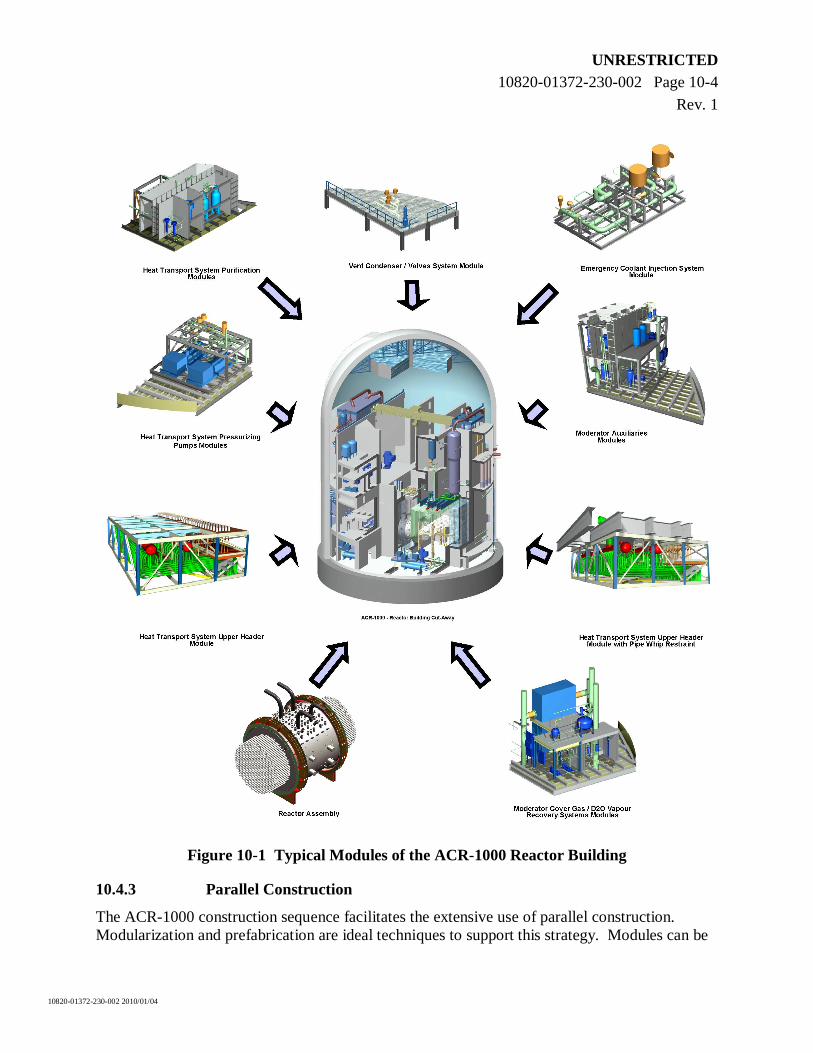
UNRESTRICTED 10820-01372-230-002 Page 10-4
Rev. 1
10820-01372-230-002 2010/01/04
Figure 10-1 Typical Modules of the ACR-1000 Reactor Building
10.4.3 Parallel Construction
The ACR-1000 construction sequence facilitates the extensive use of parallel construction. Modularization and prefabrication are ideal techniques to support this strategy. Modules can be
UNRESTRICTED 10820-01372-230-002 Page 10-5
Rev. 1
10820-01372-230-002 2010/01/04
fabricated in a shop or another location on site while the civil work is progressing towards getting ready to receive them. Major blocks of work are separated into mini-projects so that they can be constructed concurrently. Durations for traditional activities are not greatly changed, but the sequencing is very different.
10.4.4 Open-Top Construction
Large scale modularization has been effectively demonstrated on both nuclear and non-nuclear large scale construction projects around the world. Recent developments in mobile cranes have made the installation of very large prefabricated modules practical. Very heavy lift (VHL) cranes have made it possible to leave the top off the containment structure and install the heavy internal items through the “open top” of the Reactor Building. The use of VHL cranes has been shown to be successful in the construction of the CANDU 6 Qinshan units.
Open-top construction is optimized by installing all major equipment, modules, and materials through the top of the Reactor Building using external cranes. The advantages of using a crane for installing equipment/modules are:
Improved access.
Shorter durations for activities.
Greater schedule logic flexibility.
Simpler rigging.
10.5 Provision for Low Fuel Reload Costs
The use of LEU in an advanced CANFLEX-ACR fuel bundle allows for an increase in fuel burnup resulting in fewer fuel bundles changed, and a smaller volume of spent fuel per MWth. This, in turn, reduces both operating costs and spent fuel storage costs. In addition, the fact that the ACR-1000 is refuelled on-power means that there is no loss of capacity factor due to refuelling operations.
UNRESTRICTED 10820-01372-230-002 Page 11-1
Rev. 1
10820-01372-230-002 2010/01/04
11. DEVELOPMENT STATUS OF TECHNOLOGIES RELEVANT TO THE ACR-1000
11.1 Technology in Support of ACR-1000
The ACR-1000 design is an evolutionary extension of the current CANDU designs and is based on the extensive fundamental and applied knowledge that is in place to support operating plants. The ACR-1000 design also incorporates proven industry advancements such as DCS technology. For an overview of the R&D program in support of the ACR-1000 design, see Section 12.
11.2 Technologies Relevant to the ACR-1000
Advanced fuel cycles are one of the technologies that AECL has been researching and testing for more than forty years; particularly methods to extend nuclear fuel resources and improve economics. The ACR-1000 design incorporates a higher burnup fuel and has the ability to burn MOX and Thorium fuels. These various fuel cycles can be easily implemented into the ACR-1000 design due to the reactor’s simple fuel bundle design and on-power fuelling capability. This is discussed further in the following papers:
Ovanes M, Chan P, Hopwood J. Thorium and Other Fuel Cycle Flexibility of ACR-1000. Proceedings of GLOBAL 2009: 2009 Sept 6-11; Paris, France. Paper No. 9123.
Chan P, Dyck G, Kuran S, Ivanco M, Hopwood J, Hastings I. Fuel Cycles – Secure Supply, Reduced Waste, Enhanced Non-Proliferation. Proceedings of PBNC 2008: 2008 Oct 13-17; Aomori, Japan. Paper No. P16P1251.
The ACR-1000 design can also be adopted for other applications. Some of these potential applications include:
a) Bitumen extraction from Alberta’s oil sands. Steam from an ACR-1000 plant can provide a continuous supply of the high quality steam required for the steam assisted gravity drainage process.
b) Hydrogen production via steam electrolysis. Steam, heat, and electricity generated from an ACR-1000 plant can be used for this process.
c) Reverse osmosis seawater desalination. An ACR-1000 power plant can supply electricity and pre-heated feedwater for this process.
The following papers expand on potential applications of the ACR-1000 design:
Hopwood J, Duffey R, Kuran S, Zhou X, Ivanco M, Rolfe B, Miller A, Mancuso C. Non-Electrical CANDU Applications. Proceedings of GLOBAL 2005; 2005 Oct 9-13; Tsukuba, Japan. Paper No. 536.
Ryland DK, Li H, Sadhankar RR, Electrolytic Hydrogen Generation Using CANDU Nuclear Reactors. Proceedings of the Second International Green Energy Conference; 2006 Jun 25-29; Oshawa, Ontario, Canada. Paper No. IGEC2-145.
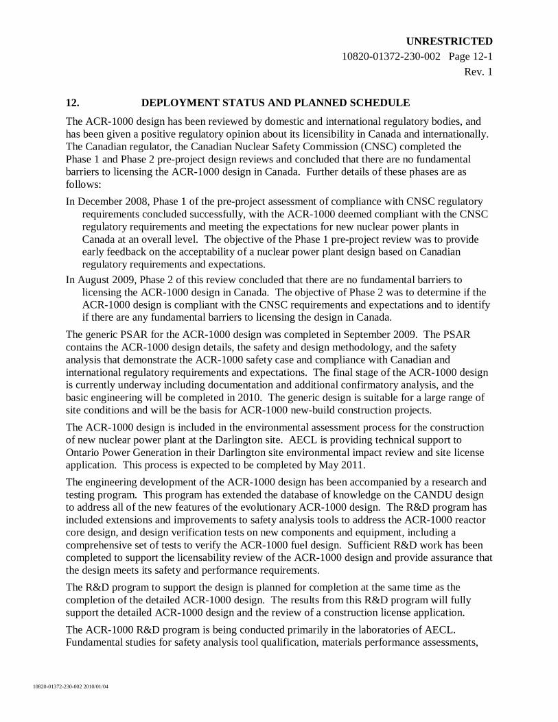
UNRESTRICTED 10820-01372-230-002 Page 12-1
Rev. 1
10820-01372-230-002 2010/01/04
12. DEPLOYMENT STATUS AND PLANNED SCHEDULE
The ACR-1000 design has been reviewed by domestic and international regulatory bodies, and has been given a positive regulatory opinion about its licensibility in Canada and internationally. The Canadian regulator, the Canadian Nuclear Safety Commission (CNSC) completed the Phase 1 and Phase 2 pre-project design reviews and concluded that there are no fundamental barriers to licensing the ACR-1000 design in Canada. Further details of these phases are as follows:
In December 2008, Phase 1 of the pre-project assessment of compliance with CNSC regulatory requirements concluded successfully, with the ACR-1000 deemed compliant with the CNSC regulatory requirements and meeting the expectations for new nuclear power plants in Canada at an overall level. The objective of the Phase 1 pre-project review was to provide early feedback on the acceptability of a nuclear power plant design based on Canadian regulatory requirements and expectations.
In August 2009, Phase 2 of this review concluded that there are no fundamental barriers to licensing the ACR-1000 design in Canada. The objective of Phase 2 was to determine if the ACR-1000 design is compliant with the CNSC requirements and expectations and to identify if there are any fundamental barriers to licensing the design in Canada.
The generic PSAR for the ACR-1000 design was completed in September 2009. The PSAR contains the ACR-1000 design details, the safety and design methodology, and the safety analysis that demonstrate the ACR-1000 safety case and compliance with Canadian and international regulatory requirements and expectations. The final stage of the ACR-1000 design is currently underway including documentation and additional confirmatory analysis, and the basic engineering will be completed in 2010. The generic design is suitable for a large range of site conditions and will be the basis for ACR-1000 new-build construction projects.
The ACR-1000 design is included in the environmental assessment process for the construction of new nuclear power plant at the Darlington site. AECL is providing technical support to Ontario Power Generation in their Darlington site environmental impact review and site license application. This process is expected to be completed by May 2011.
The engineering development of the ACR-1000 design has been accompanied by a research and testing program. This program has extended the database of knowledge on the CANDU design to address all of the new features of the evolutionary ACR-1000 design. The R&D program has included extensions and improvements to safety analysis tools to address the ACR-1000 reactor core design, and design verification tests on new components and equipment, including a comprehensive set of tests to verify the ACR-1000 fuel design. Sufficient R&D work has been completed to support the licensability review of the ACR-1000 design and provide assurance that the design meets its safety and performance requirements.
The R&D program to support the design is planned for completion at the same time as the completion of the detailed ACR-1000 design. The results from this R&D program will fully support the detailed ACR-1000 design and the review of a construction license application.
The ACR-1000 R&D program is being conducted primarily in the laboratories of AECL. Fundamental studies for safety analysis tool qualification, materials performance assessments,
UNRESTRICTED 10820-01372-230-002 Page 12-2
Rev. 1
10820-01372-230-002 2010/01/04
and irradiated fuel performance are carried out mainly at AECL’s 3000-person Chalk River Laboratories. Component and equipment verification tests are mainly carried out at AECL’s engineering test facilities at Sheridan Park. AECL’s extensive test facilities and research capabilities are complemented by limited focussed work at external organizations including thermalhydraulics tests at Stern Laboratories and fuel development at GE-Hitachi Nuclear Energy Canada Inc.
UNRESTRICTED 10820-01372-230-002 Page 13-1
Rev. 1
10820-01372-230-002 2010/01/04
13. REFERENCES
[1] IAEA NS-R-1, “Safety of Nuclear Power Plants: Design”, International Atomic Energy Agency, 2000.
[2] CNSC RD-337, “Design of New Nuclear Power Plants”, Canadian Nuclear Safety Commission, November 2008.
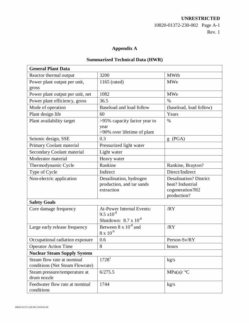
UNRESTRICTED 10820-01372-230-002 Page A-1
Rev. 1
10820-01372-230-002 2010/01/04
Appendix A
Summarized Technical Data (HWR)
General Plant Data Reactor thermal output 3200 MWth Power plant output per unit, gross
1165 (rated) MWe
Power plant output per unit, net 1082 MWe Power plant efficiency, gross 36.5 % Mode of operation Baseload and load follow (baseload, load follow) Plant design life 60 Years Plant availability target >95% capacity factor year to
year >90% over lifetime of plant
%
Seismic design, SSE 0.3 g (PGA) Primary Coolant material Pressurized light water Secondary Coolant material Light water Moderator material Heavy water Thermodynamic Cycle Rankine Rankine, Brayton? Type of Cycle Indirect Direct/Indirect Non-electric application Desailination, hydrogen
production, and tar sands extraction
Desalination? District heat? Industrial cogeneration?H2 production?
Safety Goals Core damage frequency At-Power Internal Events:
9.5 x10⁻⁸ Shutdown: 8.7 x 10⁻⁸
/RY
Large early release frequency Between 8 x 10⁻⁸ and 8 x 10⁻⁹
/RY
Occupational radiation exposure 0.6 Person-Sv/RY Operator Action Time 8 hours Nuclear Steam Supply System Steam flow rate at nominal conditions (Net Steam Flowrate)
17281 kg/s
Steam pressure/temperature at drum nozzle
6/275.5 MPa(a)/ °C
Feedwater flow rate at nominal conditions
1744 kg/s
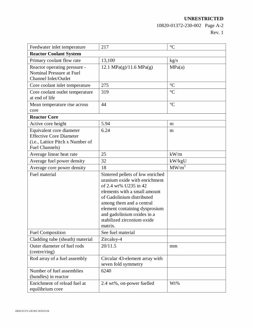
UNRESTRICTED 10820-01372-230-002 Page A-2
Rev. 1
10820-01372-230-002 2010/01/04
Feedwater inlet temperature 217 °C Reactor Coolant System Primary coolant flow rate 13,100 kg/s Reactor operating pressure - Nominal Pressure at Fuel Channel Inlet/Outlet
12.1 MPa(g)/11.6 MPa(g) MPa(a)
Core coolant inlet temperature 275 °C Core coolant outlet temperature at end of life
319 °C
Mean temperature rise across core
44 °C
Reactor Core Active core height 5.94 m Equivalent core diameter Effective Core Diameter (i.e., Lattice Pitch x Number of Fuel Channels)
6.24 m
Average linear heat rate 25 kW/m Average fuel power density 32 kW/kgU Average core power density 18 MW/m3 Fuel material Sintered pellets of low enriched
uranium oxide with enrichment of 2.4 wt% U235 in 42 elements with a small amount of Gadolinium distributed among them and a central element containing dysprosium and gadolinium oxides in a stabilized zirconium oxide matrix.
Fuel Composition See fuel material Cladding tube (sheath) material Zircaloy-4 Outer diameter of fuel rods (centre/ring)
20/11.5 mm
Rod array of a fuel assembly Circular 43-element array with seven fold symmetry
Number of fuel assemblies (bundles) in reactor
6240
Enrichment of reload fuel at equilibrium core
2.4 wt%, on-power fuelled Wt%
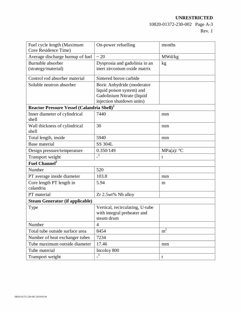
UNRESTRICTED 10820-01372-230-002 Page A-3
Rev. 1
10820-01372-230-002 2010/01/04
Fuel cycle length (Maximum Core Residence Time)
On-power refuelling months
Average discharge burnup of fuel ~ 20 MWd/kg Burnable absorber (strategy/material)
Dysprosia and gadolinia in an inert zirconium oxide matrix
kg
Control rod absorber material Sintered boron carbide Soluble neutron absorber Boric Anhydride (moderator
liquid poison system) and Gadolinium Nitrate (liquid injection shutdown units)
Reactor Pressure Vessel (Calandria Shell)2 Inner diameter of cylindrical shell
7440 mm
Wall thickness of cylindrical shell
30 mm
Total length, inside 5940 mm Base material SS 304L Design pressure/temperature 0.350/149 MPa(a)/ °C Transport weight -3 t Fuel Channel2 Number 520 PT average inside diameter 103.8 mm Core length PT length in calandria
5.94 m
PT material Zr 2.5wt% Nb alloy Steam Generator (if applicable) Type Vertical, recirculating, U-tube
with integral preheater and steam drum
Number 4 Total tube outside surface area 8454 m2 Number of heat exchanger tubes 7234 Tube maximum outside diameter 17.46 mm Tube material Incoloy 800 Transport weight -3 t
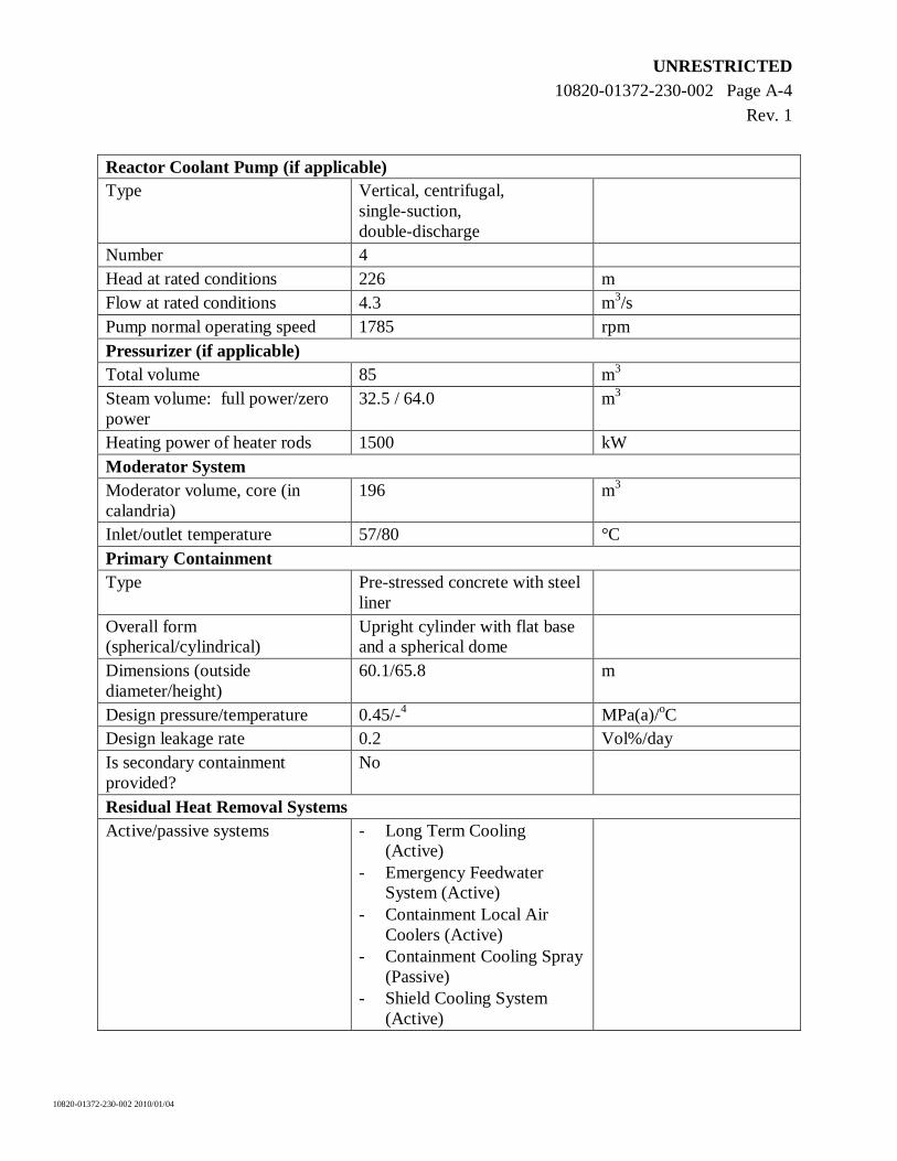
UNRESTRICTED 10820-01372-230-002 Page A-4
Rev. 1
10820-01372-230-002 2010/01/04
Reactor Coolant Pump (if applicable) Type Vertical, centrifugal,
single-suction, double-discharge
Number 4 Head at rated conditions 226 m Flow at rated conditions 4.3 m3/s Pump normal operating speed 1785 rpm Pressurizer (if applicable) Total volume 85 m3 Steam volume: full power/zero power
32.5 / 64.0 m3
Heating power of heater rods 1500 kW Moderator System Moderator volume, core (in calandria)
196 m3
Inlet/outlet temperature 57/80 °C Primary Containment Type Pre-stressed concrete with steel
liner
Overall form (spherical/cylindrical)
Upright cylinder with flat base and a spherical dome
Dimensions (outside diameter/height)
60.1/65.8 m
Design pressure/temperature 0.45/-4 MPa(a)/oC Design leakage rate 0.2 Vol%/day Is secondary containment provided?
No
Residual Heat Removal Systems Active/passive systems - Long Term Cooling
(Active) - Emergency Feedwater
System (Active) - Containment Local Air
Coolers (Active) - Containment Cooling Spray
(Passive) - Shield Cooling System
(Active)
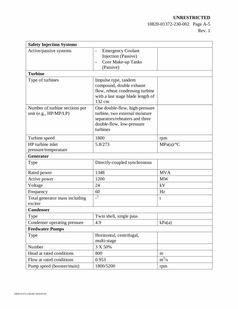
UNRESTRICTED 10820-01372-230-002 Page A-5
Rev. 1
10820-01372-230-002 2010/01/04
Safety Injection Systems Active/passive systems - Emergency Coolant
Injection (Passive) - Core Make-up Tanks
(Passive)
Turbine Type of turbines Impulse type, tandem
compound, double exhaust flow, reheat condensing turbine with a last stage blade length of 132 cm
Number of turbine sections per unit (e.g., HP/MP/LP)
One double-flow, high-pressure turbine, two external moisture separators/reheaters and three double-flow, low-pressure turbines
Turbine speed 1800 rpm HP turbine inlet pressure/temperature
5.8/273 MPa(a)/°C
Generator Type Directly-coupled synchronous
Rated power 1348 MVA Active power 1200 MW Voltage 24 kV Frequency 60 Hz Total generator mass including exciter
-3 t
Condenser Type Twin shell, single pass Condenser operating pressure 4.9 kPa(a) Feedwater Pumps Type Horizontal, centrifugal,
multi-stage
Number 3 X 50% Head at rated conditions 800 m Flow at rated conditions 0.953 m3/s Pump speed (booster/main) 1800/5200 rpm
UNRESTRICTED 10820-01372-230-002 Page A-6
Rev. 1
10820-01372-230-002 2010/01/04
Notes:
1. Assumes a maximum 1% blowdown.
2. In a CANDU reactor core, the reactor coolant pressure boundary is the pressure tubes instead of a reactor pressure vessel for LWRs/PWRs. The pressure tubes are contained within calandria tubes which together form the fuel channels. The fuel channels are, in turn, enclosed in a calandria vessel filled with moderator.
3. The transport weight is dependant on various criteria, including packaging requirements.
4. The long-term containment design temperature is 55oC.