ABB i-bus KNX Room Master Premium RM/S 2.1 Product Manual · 4.7.3 Download ... 4.7.4 Reaction on...
328
ABB i-bus ® KNX Room Master Premium RM/S 2.1 Product Manual
Transcript of ABB i-bus KNX Room Master Premium RM/S 2.1 Product Manual · 4.7.3 Download ... 4.7.4 Reaction on...
ABB i-bus® KNX Room Master Premium RM/S 2.1 Product Manual

ABB i-bus KNX Contents
RM/S 2.1 | 2CDC 514 046 D0203 i
Contents Page
1 General ................................................................................................. 5 1.1 Using the product manual ............................................................................................................. 5 1.1.1 Structure of the product manual ................................................................................................... 6 1.1.2 Notes ............................................................................................................................................ 6 1.2 Room Master: Areas of application ............................................................................................... 7 1.2.1 Hotel ............................................................................................................................................. 7 1.2.2 Hospitals ....................................................................................................................................... 7 1.2.3 Residential homes ........................................................................................................................ 7 1.2.4 Apartments ................................................................................................................................... 8 1.3 Product and functional overview ................................................................................................... 9 1.4 Function of the room states ........................................................................................................ 11 1.4.1 Triggering of a KNX scene in the Room Master ......................................................................... 14
2 Device Technology ............................................................................ 15 2.1 Technical data ............................................................................................................................ 15 2.1.1 Electronic outputs ....................................................................................................................... 16 2.1.2 Binary inputs ............................................................................................................................... 16 2.1.3 Rated current output 6 A ............................................................................................................ 17 2.1.4 Output lamp load 6 A .................................................................................................................. 18 2.1.5 Rated current output 16 A .......................................................................................................... 18 2.1.6 Output lamp load 16 A ................................................................................................................ 19 2.1.7 Rated current output 20 A .......................................................................................................... 20 2.1.8 Output lamp load 20 A ................................................................................................................ 21 2.2 Connection schematics .............................................................................................................. 22 2.3 Dimension drawing ..................................................................................................................... 24 2.4 Assembly and installation ........................................................................................................... 25
3 Commissioning .................................................................................. 27 3.1 Overview .................................................................................................................................... 27 3.1.1 Functions of the inputs ............................................................................................................... 28 3.1.2 Functions of the outputs ............................................................................................................. 29 3.2 Parameters ................................................................................................................................. 30 3.2.1 Parameter window Device information ....................................................................................... 31 3.2.2 Parameter window General ........................................................................................................ 32 3.2.3 Parameter windowEnable Inputs a…f ....................................................................................... 34 3.2.3.1 Parameter window a: Switch Sensor .......................................................................................... 36 3.2.3.1.1 Parameter Distinction between short and long operation – no ................................................... 39 3.2.3.1.2 Parameter Distinction between short and long operation – yes .................................................. 46 3.2.3.1.3 Special function Fault monitoring input ....................................................................................... 47 3.2.3.2 Parameter window a: Dim Sensor .............................................................................................. 50 3.2.3.3 Parameter window a: Blind sensor ............................................................................................. 55 3.2.3.4 Parameter window a: Value/Forced operation ............................................................................ 59 3.2.3.4.1 Parameter Distinction between short and long operation – no ................................................... 61 3.2.3.4.2 Parameter Distinction between short and long operation – yes .................................................. 66 3.2.4 Parameter window Enable Inputs g…l Enable Inputs m…r ........................................................ 66 3.2.5 Parameter window Enable Outputs A…D ................................................................................... 67 3.2.5.1 Parameter window A: Output (20 A/16 AX C-Load) .................................................................... 68 3.2.5.1.1 Parameter window A: Output - Time ........................................................................................... 74 3.2.5.1.2 Parameter window A: Output - Scene ........................................................................................ 80 3.2.5.1.3 Parameter window A: Output - Logic .......................................................................................... 83 3.2.6 Parameter window Enable Outputs E…J ................................................................................... 85 3.2.6.1 Parameter window E: Output (6 A) ............................................................................................. 87 3.2.6.1.1 Parameter window E: Output - Time, Flashing ........................................................................... 88
ABB i-bus KNX Contents
ii 2CDC 514 046 D0203 | RM/S 2.1
3.2.7 Parameter window Enable Outputs K…U .................................................................................. 91 3.2.7.1 Parameter window K: Shutter (6 A) ........................................................................................... 93 3.2.7.1.1 Parameter window K: Shutter (6 A) - Drive ................................................................................ 97 3.2.7.1.2 Parameter window K: Shutter (6 A) - Automatic ........................................................................ 99 3.2.7.1.3 Parameter window K: Shutter (6 A) - Scene ............................................................................ 102 3.2.7.1.4 Parameter window K: Shutter (6 A) - Safety ............................................................................ 105 3.2.7.2 Parameter window K: Blind (6 A) ............................................................................................. 107 3.2.7.2.1 Parameter window K: Blind (6A) - Drive .................................................................................. 111 3.2.7.2.2 Parameter window K: Blind (6A) - Automatic ........................................................................... 112 3.2.7.2.3 Parameter window K: Blind (6A) - Scene ................................................................................. 112 3.2.7.2.4 Parameter window K: Blind (6A) - Safety ................................................................................. 112 3.2.7.3 Parameter window L, M, N: Fan (3 x 6 A) multi-level ............................................................... 113 3.2.7.3.1 Parameter window- Status messages ..................................................................................... 119 3.2.7.3.2 Parameter window - Automatic operation ................................................................................ 123 3.2.7.3.3 Parameter window - Direct operation ....................................................................................... 129 3.2.7.4 Parameter window L, M, N: Fan (3 x 6 A) two speed ............................................................... 131 3.2.7.5 Parameter window L, M, N: Fan (3 x 6 A) one-level ................................................................ 132 3.2.7.5.1 Parameter window- Status messages ..................................................................................... 135 3.2.7.5.2 Parameter window - Automatic operation ................................................................................ 137 3.2.8 Parameter window Control input .............................................................................................. 141 3.2.8.1 HVAC system – 1 Control value/2 pipe .................................................................................... 143 3.2.8.2 HVAC-System – 1 Control value/4 pipe, with switching object ................................................ 144 3.2.8.3 HVAC system – 2 Control values/2 pipe .................................................................................. 145 3.2.8.4 HVAC-System – 2 Control values/2 pipe, with switching object ............................................... 146 3.2.8.5 HVAC system – 2 Control values/4 pipe .................................................................................. 147 3.2.9 Parameter window O, P: Valve HEATING (0.5 A AC) – 3 point, opening and closing ............. 148 3.2.10 Parameter window O, P: Valve HEATING (0.5 A AC) – Continuous, PWM ............................. 151 3.2.10.1 Parameter window - Function .................................................................................................. 154 3.2.10.2 Parameter window - Curve ...................................................................................................... 158 3.2.11 Parameter window Q, R: Valve COOLING (0.5 A AC) ............................................................. 160 3.2.12 Parameter window Enable Room Scenario 1…16 ................................................................... 161 3.2.12.1 Parameter window Room Scenario x ....................................................................................... 163 3.2.13 Commissioning without bus voltage ......................................................................................... 167 3.3 Communication objects ........................................................................................................... 168 3.3.1 Brief overview of the communication objects ........................................................................... 168 3.3.2 Communication objects General .............................................................................................. 170 3.3.3 Communication objects Room Scenario .................................................................................. 171 3.3.4 Communication objects L, M, N: Fan (3 x 6 A) ........................................................................ 173 3.3.4.1 Communication objects Multi-level fan .................................................................................... 173 3.3.4.2 Communication objects Fan one-level ..................................................................................... 178 3.3.5 Communication objects Control input ...................................................................................... 182 3.3.5.1 Communication objects HVAC System – 1 Control value/2 pipe ............................................. 182 3.3.5.2 Communication objects HVAC System 1 Control value/4 pipe, with switching object ............. 183 3.3.5.3 Communication objects HVAC System – 2 Control values/2 pipe ........................................... 184 3.3.5.4 Communication objects HVAC System 2 Control values/2 pipe, with switching object ............ 185 3.3.5.5 Communication objects HVAC System – 2 Control values/4 pipe ........................................... 186 3.3.5.6 Communication object Fault control value ............................................................................... 187 3.3.6 Communication objects Valve HEATING ................................................................................. 188 3.3.7 Communication objects Valve COOLING ................................................................................ 190 3.3.8 Communication objects Inputs a…r ......................................................................................... 191 3.3.8.1 Communication objects Switch sensor .................................................................................... 192 3.3.8.2 Communication objects Switch/Dim sensor ............................................................................. 193 3.3.8.3 Communication objects Blind sensor ....................................................................................... 194 3.3.8.4 Communication objects Value/forced operation ....................................................................... 196 3.3.9 Communication objects Outputs .............................................................................................. 197 3.3.9.1 Communication objects Output A ............................................................................................ 198 3.3.10 Communication objects Output K: Blind and shutter ................................................................ 201
ABB i-bus KNX Contents
RM/S 2.1 | 2CDC 514 046 D0203 iii
4 Planning and Application ................................................................ 207 4.1 Input ......................................................................................................................................... 207 4.1.1 Operation with central function (Switch light) ............................................................................ 208 4.1.2 Fault monitoring input ............................................................................................................... 209 4.1.3 Operation of the illumination (dimming lights) ........................................................................... 211 4.1.4 Operation of blinds ................................................................................................................... 212 4.2 Output ....................................................................................................................................... 215 4.2.1 Function chart ........................................................................................................................... 215 4.2.2 Function Time ........................................................................................................................... 216 4.2.2.1 Staircase lighting ...................................................................................................................... 217 4.2.2.2 Switching ON and OFF delay ................................................................................................... 218 4.2.2.3 Flashing .................................................................................................................................... 219 4.2.3 Connection/logic ....................................................................................................................... 220 4.2.4 Function Scene ......................................................................................................................... 222 4.3 Output K ................................................................................................................................... 223 4.3.1 Drive types................................................................................................................................ 223 4.3.2 General functions ..................................................................................................................... 223 4.3.2.1 Travel times .............................................................................................................................. 223 4.3.2.2 Safety ....................................................................................................................................... 225 4.3.2.3 Determination of the current position ........................................................................................ 225 4.3.2.4 Move to position in % [0…100] ................................................................................................. 226 4.3.3 Automatic control ...................................................................................................................... 226 4.3.3.1 Automatic sun protection .......................................................................................................... 227 4.3.3.2 Status feedback ........................................................................................................................ 232 4.4 Heating, ventilation, climate control with Fan Coil units ............................................................ 233 4.4.1 Terms ....................................................................................................................................... 233 4.4.2 Fan operation ........................................................................................................................... 234 4.4.2.1 Fan in a two-way connection .................................................................................................... 235 4.4.2.2 Fan with speed switching ......................................................................................................... 235 4.4.3 Configuration of a HVAC system with Fan Coil units ................................................................ 235 4.4.4 Design of a Fan Coil unit .......................................................................................................... 236 4.4.5 Pipe systems ............................................................................................................................ 237 4.4.5.1 2 pipe system, configuration ..................................................................................................... 238 4.4.5.2 2 pipe system HEATING and COOLING .................................................................................. 239 4.4.5.3 2 pipe system HEATING or COOLING ..................................................................................... 240 4.4.5.4 3 pipe system, configuration ..................................................................................................... 241 4.4.5.5 4 pipe system, configuration ..................................................................................................... 242 4.5 System configuration with the Room Master ............................................................................ 243 4.5.1 Automatic operation .................................................................................................................. 243 4.5.2 Direct operation ........................................................................................................................ 245 4.5.3 Switchover between automatic and direct operation ................................................................ 245 4.5.4 Logic of the stage switching...................................................................................................... 246 4.5.5 Fan operation functional diagram ............................................................................................. 247 4.6 Valve drives, valves and controller ........................................................................................... 248 4.6.1 Electromotor valve drives ......................................................................................................... 248 4.6.2 Electro-thermal valve drives ..................................................................................................... 248 4.6.3 Valve curve ............................................................................................................................... 249 4.6.4 Control types ............................................................................................................................ 252 4.6.4.1 Continuous control .................................................................................................................... 252 4.6.4.2 Pulse width modulation (PWM) ................................................................................................. 253 4.6.4.3 Pulse width modulation – calculation ........................................................................................ 255 4.7 Behaviour with, … .................................................................................................................... 256 4.7.1 Bus voltage recovery ................................................................................................................ 256 4.7.2 Reset via bus ............................................................................................................................ 258 4.7.3 Download ................................................................................................................................. 259 4.7.4 Reaction on bus voltage failure ................................................................................................ 260 4.8 Priorities with, … ....................................................................................................................... 261 4.8.1 Valve HEATING/COOLING ...................................................................................................... 261 4.9 Fast heat up/cool down ............................................................................................................ 262 4.9.1 Heat up ..................................................................................................................................... 262 4.9.2 Cooling down ............................................................................................................................ 263 4.10 Configuration of a distribution board with Room Master Premium ............................................ 264
ABB i-bus KNX Contents
iv 2CDC 514 046 D0203 | RM/S 2.1
5 Pre-configuration ............................................................................. 265 5.1 Pre-configured Room Scenarios .............................................................................................. 265 5.2 Prerequisites for commissioning .............................................................................................. 265 5.3 Preconfigured binary inputs ..................................................................................................... 267 5.3.1 Block binary inputs ................................................................................................................... 268 5.3.2 Operating modes ..................................................................................................................... 269 5.3.2.1 Operating mode Switch sensor ................................................................................................ 270 5.3.2.2 Operating mode Blind sensor .................................................................................................. 273 5.3.2.3 Operating mode Value/Forced operation ................................................................................. 274 5.3.3 Scan binary inputs ................................................................................................................... 276 5.4 Preconfigured outputs .............................................................................................................. 277 5.5 Triggering Room Scenarios ..................................................................................................... 278 5.5.1 Room Scenario internal triggering ........................................................................................... 279 5.5.2 Room scenario External triggering ........................................................................................... 281 5.5.3 Overview table for triggering Room Scenarios ......................................................................... 283 5.6 Room Scenario 1 ..................................................................................................................... 284 5.6.1 Room Scenario 1 in action ....................................................................................................... 286 5.7 Room Scenario 2 ..................................................................................................................... 287 5.7.1 Room Scenario 2 in action ....................................................................................................... 289 5.8 Room Scenario 3 ..................................................................................................................... 290 5.8.1 Room Scenario 3 in action ....................................................................................................... 292 5.9 Room Scenario 4 ..................................................................................................................... 293 5.9.1 Room Scenario 4 in action ....................................................................................................... 295 5.10 Room Scenario 5 ..................................................................................................................... 296 5.10.1 Room Scenario 5 in action ....................................................................................................... 298 5.11 Room Scenario 6 ..................................................................................................................... 300 5.11.1 Room Scenario 6 in action ....................................................................................................... 302 5.12 Room Scenario 7 ..................................................................................................................... 303 5.12.1 Room Scenario 7 in action ....................................................................................................... 305 5.13 Room Scenario 8 ..................................................................................................................... 306 5.13.1 Room Scenario 8 in action ....................................................................................................... 308 5.14 Special feature Switch sensor .................................................................................................. 309 5.15 Special feature Blind sensor .................................................................................................... 310 5.15.1 Special feature Blind sensor with external Blind actuator ........................................................ 311 5.16 Special feature Acknowledge emergency ................................................................................ 312 5.17 Special feature RDF/A ............................................................................................................. 314 5.18 Special feature Push button in hall .......................................................................................... 316 5.19 Special feature Push button do not disturb .............................................................................. 316 5.20 Special feature Push button room service ............................................................................... 316 5.21 Special feature Bathroom fan .................................................................................................. 316
A Appendix ........................................................................................... 317 A.1 Scope of delivery ..................................................................................................................... 317 A.2 Status byte fan, forced/operation ............................................................................................. 318 A.3 Status byte Blind/Shutters........................................................................................................ 319 A.4 Code table scene (8 bit) ........................................................................................................... 320 A.5 Input 4 bit dimming telegram .................................................................................................... 321 A.6 Ordering information ................................................................................................................ 322 A.7 Notizen .................................................................................................................................... 323
ABB i-bus KNX General
RM/S 2.1 | 2CDC 514 046 D0203 5
1 General
The Room Master Premium RM/S 2.1 provides intelligent engineering technology for hotel rooms and apartments.
Modern buildings require intelligent building engineering technology for safe and efficient operation. Many buildings world-wide already utilise the full potential of networked electrical installations.
Hotels, hospitals, senior citizen and student residential homes, assisted living accommodation and much, much more: the Room Master covers new possibilities for buildings in the residential and hotel sectors.
The Room Master has been developed for all rooms of this type. It covers all requirements of the electrical installation of this application and offers the following functions in compact form:
• Switch lighting
• Control heating/cooling
• Shading (using blinds or curtains)
• Switching of electrical sockets and loads
In addition to these basic functions, further automation functions can be implemented by a combination with a presence detector. The communication of the devices via the KNX bus also enables control func-tions as well as sending of emergency signals from the rooms to a control centre.
The integration into a hotel management system enables the efficient management and provision of rooms. For example, when a guest checks out, the room is automatically set to standby mode.
Note
The device is in the ready to operate state on delivery. The pre-configuration allows immediate use of the Room Master Premium after it is connected.
1.1 Using the product manual
This manual provides you with detailed technical information relating to the function, installation and pro-gramming of the ABB i-bus® KNX VAA/S x.230.2.1. The application of the device is explained using exam-ples.
This manual is divided into the following sections:
Chapter 1 General
Chapter 2 Device technology
Chapter 3 Commissioning
Chapter 4 Planning and application
Chapter 5 Device technology
Chapter A Appendix
ABB i-bus KNX General
6 2CDC 514 046 D0203 | RM/S 2.1
1.1.1 Structure of the product manual
All parameters are described in chapter 3.
The default settings listed there do not correspond with the pre-configured version, which can be down-loaded on our website at www.abb.com/knx.
In chapter 5, you will find all of the pre-configured settings in tabular form as well as more detailed expla-nations concerning the function of the room states. The pre-configuration complies with the default delivery state. These can be re-established in the application by using the Standard button.
1.1.2 Notes
Notes and safety instructions are represented as follows in this manual:
Note
Tips for usage and operation
Examples
Application examples, installation examples, programming examples
Important
These safety instructions are used as soon as there is danger of a malfunction without risk of damage or injury.
Caution These safety instructions are used as soon as there is danger of a malfunction without risk of damage or injury.
Danger These safety instructions are used if there is a danger for life and limb with inappropriate use.
Danger These safety instructions are used if there is a danger to life with inappropriate use.
ABB i-bus KNX General
RM/S 2.1 | 2CDC 514 046 D0203 7
1.2 Room Master: Areas of application
1.2.1 Hotel
The Room Master Premium offers all functions which are required in a modern hotel room. During opera-tion, a range of advantages are achieved in comparison to a conventional installation:
• Comfortable and simple operation of the room functions by the guests
• Temperature control dependent on the season, external temperature and occupancy
• Transmission of messages to the reception, e.g. clean the room, emergency alarm
• Fast localization of faults in the rooms and simplified room maintenance
The advantages of the Room Master are obvious not just during operation, but also for planning:
• World-wide use
• Compact design: can be installed in a simple distribution board together with circuit-breakers, see Configuration of a distribution board with Room Master Premium, page 264.
• A standard solution for many projects.
1.2.2 Hospitals
When used in hospitals and buildings with a similar purpose, the Room Master features many functions which support the efficient running of a modern operation:
• Simple operation of the room functions by the patients, e.g. automatic control of the room climate
• Day/night service
• Indication of the ward round
• Remote control of the room and display of the room state in the nurses station
• Fast localization of faults in the rooms and simplified room maintenance
1.2.3 Residential homes
The Room Master enables comfort and security in residential homes and supports senior citizens in their daily routine:
• Simple operation of the room functions
• Automatic control of the room climate
• Automatic transmission of messages to the control station, e.g. emergency signals
• Fast localisation of faults in the rooms
• Indication of room states in the control station
• Day/night service

ABB i-bus KNX General
8 2CDC 514 046 D0203 | RM/S 2.1
1.2.4 Apartments
Apartments gain in both their appeal and the quality of life they offer with the Room Master – decisive fac-tors for sale and rental:
• Automatic switching of different lighting arrangements in the room
• Automatic control of heating and cooling
• Shading using shutters or curtains
• Comfortable and simple operation of the room functions
ABB i-bus KNX General
RM/S 2.1 | 2CDC 514 046 D0203 9
1.3 Product and functional overview
The Room Master Premium RM/S is used as a single room solution specially for hotel rooms. The RM/S is used to control the lighting, the heating and the air-conditioning as well as the blinds. The input signals are detected via binary inputs or directly via the sensors connected to the KNX.
Hotel management systems can directly access the RM/S via the ABB i-bus® and activate controls in the room. Accordingly, it is possible to quickly adapt the hotel room to individual customers' and guests' re-quirements.
The Room Master is a modular installation device with a module width of 12 space units in Pro M Design for installation in the distribution board. The connection to the ABB i-bus is established using the front side bus connection terminal. The Room Master Premium does not require an auxiliary supply. The as-signment of the physical addresses as well as the parameterization is carried out with Engineering Tool Software ETS.
The RM/S 2.1 controls a single-phase fan with up to three fan speeds via a step or changeover control. This ensures that no two fan speeds can be switched on simultaneously with a changeover control. An ad-ditional programmable switch-over delay is provided for this purpose. Three-phase drives are not support-ed.
Electromotor or electro-thermal actuator drives for HEATING and COOLING as well as multi-speed fans can be connected directly to the Room Master. The outputs of the actuator drives (valves) are short-circuit protected by self-restoring fuses.
A changeover contact is available for control of a blind or a curtain. A separate floating contact is available for the connection of an auxiliary electrical heating system. Nine outputs are provided for direct connection of lighting circuits. This include:
• Lamps on the left/right of the bed
• Bathroom and entrance lighting
• Two room illuminations
• Indicator lamps before the room door for Do not disturb, Room service and Room occupied
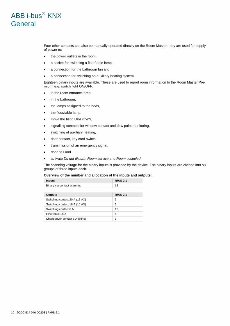
ABB i-bus KNX General
10 2CDC 514 046 D0203 | RM/S 2.1
Four other contacts can also be manually operated directly on the Room Master; they are used for supply of power to:
• the power outlets in the room,
• a socket for switching a floor/table lamp,
• a connection for the bathroom fan and
• a connection for switching an auxiliary heating system.
Eighteen binary inputs are available. These are used to report room information to the Room Master Pre-mium, e.g. switch light ON/OFF:
• in the room entrance area,
• in the bathroom,
• the lamps assigned to the beds,
• the floor/table lamp,
• move the blind UP/DOWN,
• signalling contacts for window contact and dew point monitoring,
• switching of auxiliary heating,
• door contact, key card switch,
• transmission of an emergency signal,
• door bell and
• activate Do not disturb, Room service and Room occupied
The scanning voltage for the binary inputs is provided by the device. The binary inputs are divided into six groups of three inputs each.
Overview of the number and allocation of the inputs and outputs: Inputs RM/S 2.1 Binary via contact scanning 18
Outputs RM/S 2.1 Switching contact 20 A (16 AX) 3 Switching contact 16 A (10 AX) 1 Switching contact 6 A 12 Electronic 0.5 A 4 Changeover contact 6 A (blind) 1
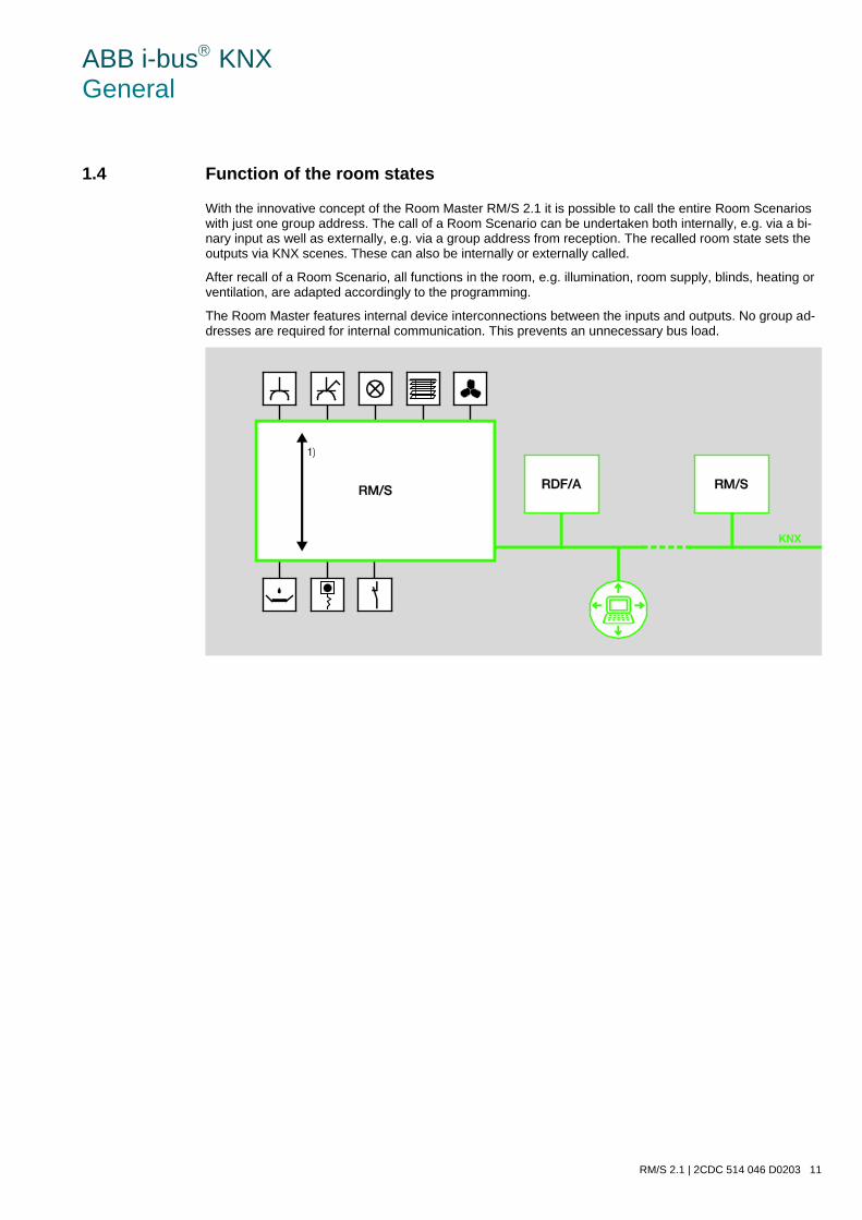
ABB i-bus KNX General
RM/S 2.1 | 2CDC 514 046 D0203 11
1.4 Function of the room states
With the innovative concept of the Room Master RM/S 2.1 it is possible to call the entire Room Scenarios with just one group address. The call of a Room Scenario can be undertaken both internally, e.g. via a bi-nary input as well as externally, e.g. via a group address from reception. The recalled room state sets the outputs via KNX scenes. These can also be internally or externally called.
After recall of a Room Scenario, all functions in the room, e.g. illumination, room supply, blinds, heating or ventilation, are adapted accordingly to the programming.
The Room Master features internal device interconnections between the inputs and outputs. No group ad-dresses are required for internal communication. This prevents an unnecessary bus load.
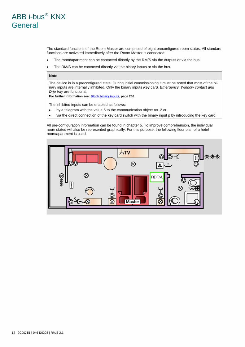
ABB i-bus KNX General
12 2CDC 514 046 D0203 | RM/S 2.1
The standard functions of the Room Master are comprised of eight preconfigured room states. All standard functions are activated immediately after the Room Master is connected:
• The room/apartment can be contacted directly by the RM/S via the outputs or via the bus.
• The RM/S can be contacted directly via the binary inputs or via the bus.
Note
The device is in a preconfigured state. During initial commissioning it must be noted that most of the bi-nary inputs are internally inhibited. Only the binary inputs Key card, Emergency, Window contact and Drip tray are functional. For further information see: Block binary inputs, page 266 The inhibited inputs can be enabled as follows: • by a telegram with the value 5 to the communication object no. 2 or • via the direct connection of the key card switch with the binary input p by introducing the key card.
All pre-configuration information can be found in chapter 5. To improve comprehension, the individual room states will also be represented graphically. For this purpose, the following floor plan of a hotel room/apartment is used.
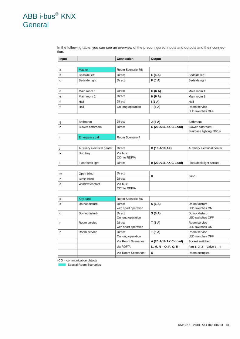
ABB i-bus KNX General
RM/S 2.1 | 2CDC 514 046 D0203 13
In the following table, you can see an overview of the preconfigured inputs and outputs and their connec-tion.
Input Connection Output
a Master Room Scenario 7/8
b Bedside left Direct E (6 A) Bedside left
c Bedside right Direct F (6 A) Bedside right
d Main room 1 Direct G (6 A) Main room 1
e Main room 2 Direct H (6 A) Main room 2
f Hall Direct I (6 A) Hall
f Hall On long operation T (6 A) Room service LED switches OFF
g Bathroom Direct J (6 A) Bathroom
h Blower bathroom Direct C (20 A/16 AX C-Load) Blower bathroom: Staircase lighting: 300 s
i Emergency call Room Scenario 4
j Auxiliary electrical heater Direct D (16 A/10 AX) Auxiliary electrical heater
k Drip tray Via bus: CO* to RDF/A
l Floor/desk light Direct B (20 A/16 AX C-Load) Floor/desk light socket
m Open blind Direct K Blind
n Close blind Direct
o Window contact Via bus: CO* to RDF/A
p Key card Room Scenario 5/6
q Do not disturb Direct with short operation
S (6 A) Do not disturb LED switches ON
q Do not disturb Direct On long operation
S (6 A) Do not disturb LED switches OFF
r Room service Direct with short operation
T (6 A) Room service LED switches ON
r Room service Direct On long operation
T (6 A) Room service LED switches OFF
Via Room Scenarios A (20 A/16 AX C-Load) Socket switched
via RDF/A L, M, N – O, P, Q, R Fan 1, 2, 3 – Valve 1…4
Via Room Scenarios U Room occupied
*CO = communication objects
Special Room Scenarios
ABB i-bus KNX General
14 2CDC 514 046 D0203 | RM/S 2.1
Further KNX devices can be integrated in the pre-configured standard functions. The room states can also be adapted, and eight further room states can also be set up. A total of 16 room states can be configured.
The 16 adjustable Room Scenarios are subdivided into groups of two, e.g. insert key card and remove key card or check in and check out.
A Room Scenario, triggered by an external 1 byte telegram or internally via the binary inputs, can trigger up to seven communication objects. These communication objects control:
• the actual Room Master, e.g. internal switching of the outputs,
• external KNX devices in the room, e.g. RDF/A, and
• external KNX devices in the building, e.g. reception.
1.4.1 Triggering of a KNX scene in the Room Master
The triggering of a single KNX scene in the Room Master offers many advantages:
• Simple integration of further sensors and actuations in the room,
• Usage of a single room group address, providing a clear demarcation to other rooms,
• Flexible configuration of further functions,
• No unnecessary bus load through internal device connections.
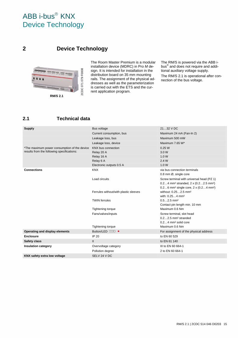
ABB i-bus KNX Device Technology
RM/S 2.1 | 2CDC 514 046 D0203 15
2 Device Technology
RM/S 2.1
The Room Master Premium is a modular installation device (MDRC) in Pro M de-sign. It is intended for installation in the distribution board on 35 mm mounting rails. The assignment of the physical ad-dresses as well as the parameterization is carried out with the ETS and the cur-rent application program.
The RM/S is powered via the ABB i-bus® and does not require and addi-tional auxiliary voltage supply. The RM/S 2.1 is operational after con-nection of the bus voltage.
2.1 Technical data
Supply Bus voltage 21…32 V DC Current consumption, bus Maximum 24 mA (Fan-In 2) Leakage loss, bus Maximum 500 mW Leakage loss, device Maximum 7.65 W* *The maximum power consumption of the device results from the following specifications:
KNX bus connection Relay 20 A Relay 16 A Relay 6 A Electronic outputs 0.5 A
0.25 W 3.0 W 1.0 W 2.4 W 1.0 W
Connections KNX via bus connection terminals 0.8 mm Ø, single core
Load circuits Ferrules without/with plastic sleeves TWIN ferrules Tightening torque
Screw terminal with universal head (PZ 1) 0.2…4 mm² stranded, 2 x (0.2…2.5 mm²) 0.2…6 mm² single core, 2 x (0.2…4 mm²) without: 0.25…2.5 mm² with: 0.25…4 mm² 0.5…2.5 mm² Contact pin length min. 10 mm Maximum 0.6 Nm
Fans/valves/inputs Tightening torque
Screw terminal, slot head 0.2…2.5 mm² stranded 0.2…4 mm² solid core Maximum 0.6 Nm
Operating and display elements Button/LED For assignment of the physical address Enclosure IP 20 to EN 60 529 Safety class II to EN 61 140 Insulation category Overvoltage category III to EN 60 664-1 Pollution degree 2 to EN 60 664-1 KNX safety extra low voltage SELV 24 V DC
2CD
C 0
71 0
79 F
0008
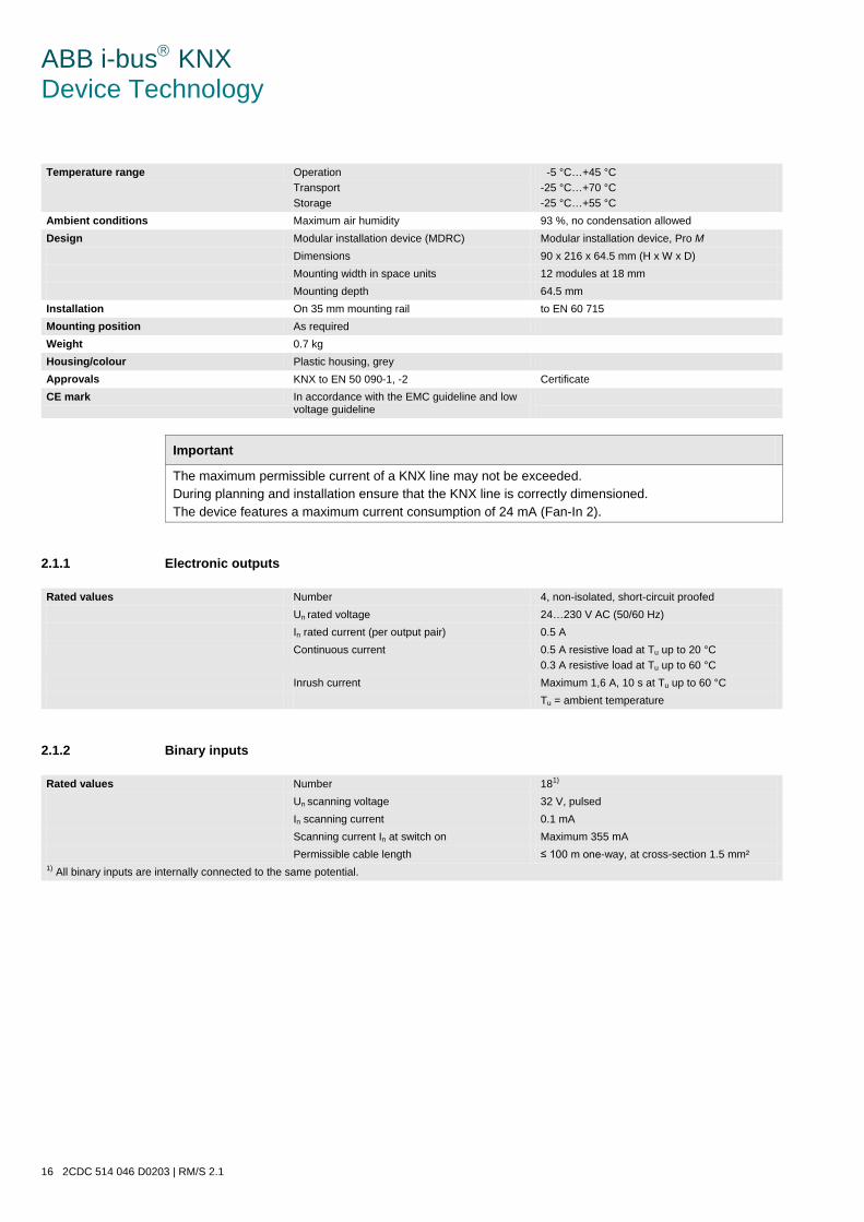
ABB i-bus KNX Device Technology
16 2CDC 514 046 D0203 | RM/S 2.1
Temperature range Operation Transport Storage
-5 °C…+45 °C -25 °C…+70 °C -25 °C…+55 °C
Ambient conditions Maximum air humidity 93 %, no condensation allowed Design Modular installation device (MDRC) Modular installation device, Pro M Dimensions 90 x 216 x 64.5 mm (H x W x D) Mounting width in space units 12 modules at 18 mm Mounting depth 64.5 mm Installation On 35 mm mounting rail to EN 60 715 Mounting position As required Weight 0.7 kg Housing/colour Plastic housing, grey Approvals KNX to EN 50 090-1, -2 Certificate CE mark In accordance with the EMC guideline and low
voltage guideline
Important
The maximum permissible current of a KNX line may not be exceeded. During planning and installation ensure that the KNX line is correctly dimensioned. The device features a maximum current consumption of 24 mA (Fan-In 2).
2.1.1 Electronic outputs
Rated values Number 4, non-isolated, short-circuit proofed Un rated voltage 24…230 V AC (50/60 Hz) In rated current (per output pair) 0.5 A Continuous current 0.5 A resistive load at Tu up to 20 °C
0.3 A resistive load at Tu up to 60 °C Inrush current Maximum 1,6 A, 10 s at Tu up to 60 °C Tu = ambient temperature
2.1.2 Binary inputs
Rated values Number 181) Un scanning voltage 32 V, pulsed In scanning current 0.1 mA Scanning current In at switch on Maximum 355 mA Permissible cable length ≤ 100 m one-way, at cross-section 1.5 mm² 1) All binary inputs are internally connected to the same potential.
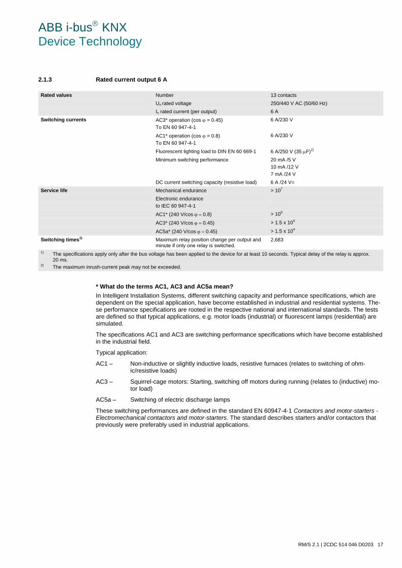
ABB i-bus KNX Device Technology
RM/S 2.1 | 2CDC 514 046 D0203 17
2.1.3 Rated current output 6 A
Rated values Number 13 contacts Un rated voltage 250/440 V AC (50/60 Hz) In rated current (per output) 6 A Switching currents AC3* operation (cos ϕ = 0.45)
To EN 60 947-4-1 6 A/230 V
AC1* operation (cos ϕ = 0.8) To EN 60 947-4-1
6 A/230 V
Fluorescent lighting load to DIN EN 60 669-1 6 A/250 V (35 µF)2) Minimum switching performance 20 mA /5 V
10 mA /12 V 7 mA /24 V
DC current switching capacity (resistive load) 6 A /24 V= Service life Mechanical endurance > 107 Electronic endurance
to IEC 60 947-4-1
AC1* (240 V/cos ϕ = 0.8) > 105
AC3* (240 V/cos ϕ = 0.45) > 1.5 x 10⁴
AC5a* (240 V/cos ϕ = 0.45) > 1.5 x 10⁴
Switching times1) Maximum relay position change per output and minute if only one relay is switched.
2,683
1) The specifications apply only after the bus voltage has been applied to the device for at least 10 seconds. Typical delay of the relay is approx. 20 ms.
2) The maximum inrush-current peak may not be exceeded.
* What do the terms AC1, AC3 and AC5a mean? In Intelligent Installation Systems, different switching capacity and performance specifications, which are dependent on the special application, have become established in industrial and residential systems. The-se performance specifications are rooted in the respective national and international standards. The tests are defined so that typical applications, e.g. motor loads (industrial) or fluorescent lamps (residential) are simulated.
The specifications AC1 and AC3 are switching performance specifications which have become established in the industrial field.
Typical application:
AC1 – Non-inductive or slightly inductive loads, resistive furnaces (relates to switching of ohm-ic/resistive loads)
AC3 – Squirrel-cage motors: Starting, switching off motors during running (relates to (inductive) mo-tor load)
AC5a – Switching of electric discharge lamps
These switching performances are defined in the standard EN 60947-4-1 Contactors and motor-starters - Electromechanical contactors and motor-starters. The standard describes starters and/or contactors that previously were preferably used in industrial applications.
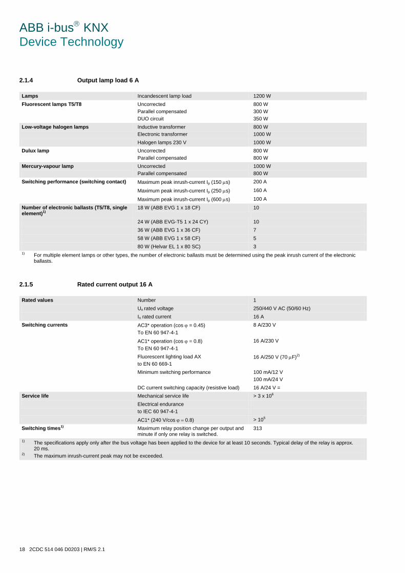
ABB i-bus KNX Device Technology
18 2CDC 514 046 D0203 | RM/S 2.1
2.1.4 Output lamp load 6 A
Lamps Incandescent lamp load 1200 W Fluorescent lamps T5/T8
Uncorrected Parallel compensated DUO circuit
800 W 300 W 350 W
Low-voltage halogen lamps Inductive transformer Electronic transformer
800 W 1000 W
Halogen lamps 230 V 1000 W Dulux lamp
Uncorrected Parallel compensated
800 W 800 W
Mercury-vapour lamp
Uncorrected Parallel compensated
1000 W 800 W
Switching performance (switching contact) Maximum peak inrush-current Ip (150 µs) 200 A
Maximum peak inrush-current Ip (250 µs) 160 A
Maximum peak inrush-current Ip (600 µs) 100 A
Number of electronic ballasts (T5/T8, single element)1)
18 W (ABB EVG 1 x 18 CF) 10
24 W (ABB EVG-T5 1 x 24 CY) 10 36 W (ABB EVG 1 x 36 CF) 7 58 W (ABB EVG 1 x 58 CF) 5 80 W (Helvar EL 1 x 80 SC) 3 1) For multiple element lamps or other types, the number of electronic ballasts must be determined using the peak inrush current of the electronic
ballasts.
2.1.5 Rated current output 16 A
Rated values Number 1 Un rated voltage 250/440 V AC (50/60 Hz) In rated current 16 A Switching currents AC3* operation (cos ϕ = 0.45)
To EN 60 947-4-1 8 A/230 V
AC1* operation (cos ϕ = 0.8) To EN 60 947-4-1
16 A/230 V
Fluorescent lighting load AX to EN 60 669-1
16 A/250 V (70 µF)2)
Minimum switching performance 100 mA/12 V 100 mA/24 V
DC current switching capacity (resistive load) 16 A/24 V = Service life Mechanical service life > 3 x 10⁶ Electrical endurance
to IEC 60 947-4-1
AC1* (240 V/cos ϕ = 0.8) > 105
Switching times1) Maximum relay position change per output and minute if only one relay is switched.
313
1) The specifications apply only after the bus voltage has been applied to the device for at least 10 seconds. Typical delay of the relay is approx. 20 ms.
2) The maximum inrush-current peak may not be exceeded.
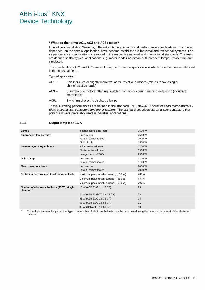
ABB i-bus KNX Device Technology
RM/S 2.1 | 2CDC 514 046 D0203 19
* What do the terms AC1, AC3 and AC5a mean? In Intelligent Installation Systems, different switching capacity and performance specifications, which are dependent on the special application, have become established in industrial and residential systems. The-se performance specifications are rooted in the respective national and international standards. The tests are defined so that typical applications, e.g. motor loads (industrial) or fluorescent lamps (residential) are simulated.
The specifications AC1 and AC3 are switching performance specifications which have become established in the industrial field.
Typical application:
AC1 – Non-inductive or slightly inductive loads, resistive furnaces (relates to switching of ohmic/resistive loads)
AC3 – Squirrel-cage motors: Starting, switching off motors during running (relates to (inductive) motor load)
AC5a – Switching of electric discharge lamps
These switching performances are defined in the standard EN 60947-4-1 Contactors and motor-starters - Electromechanical contactors and motor-starters. The standard describes starter and/or contactors that previously were preferably used in industrial applications.
2.1.6 Output lamp load 16 A
Lamps Incandescent lamp load 2500 W Fluorescent lamps T5/T8
Uncorrected Parallel compensated DUO circuit
2500 W 1500 W 1500 W
Low-voltage halogen lamps Inductive transformer Electronic transformer
1200 W 1500 W
Halogen lamps 230 V 2500 W Dulux lamp
Uncorrected Parallel compensated
1100 W 1100 W
Mercury-vapour lamp
Uncorrected Parallel compensated
2000 W 2000 W
Switching performance (switching contact) Maximum peak inrush-current Ip (150 µs) 400 A
Maximum peak inrush-current Ip (250 µs) 320 A
Maximum peak inrush-current Ip (600 µs) 200 A
Number of electronic ballasts (T5/T8, single element)1)
18 W (ABB EVG 1 x 18 CF) 23
24 W (ABB EVG-T5 1 x 24 CY) 23 36 W (ABB EVG 1 x 36 CF) 14 58 W (ABB EVG 1 x 58 CF) 11 80 W (Helvar EL 1 x 80 SC) 10 1) For multiple element lamps or other types, the number of electronic ballasts must be determined using the peak inrush current of the electronic
ballasts.
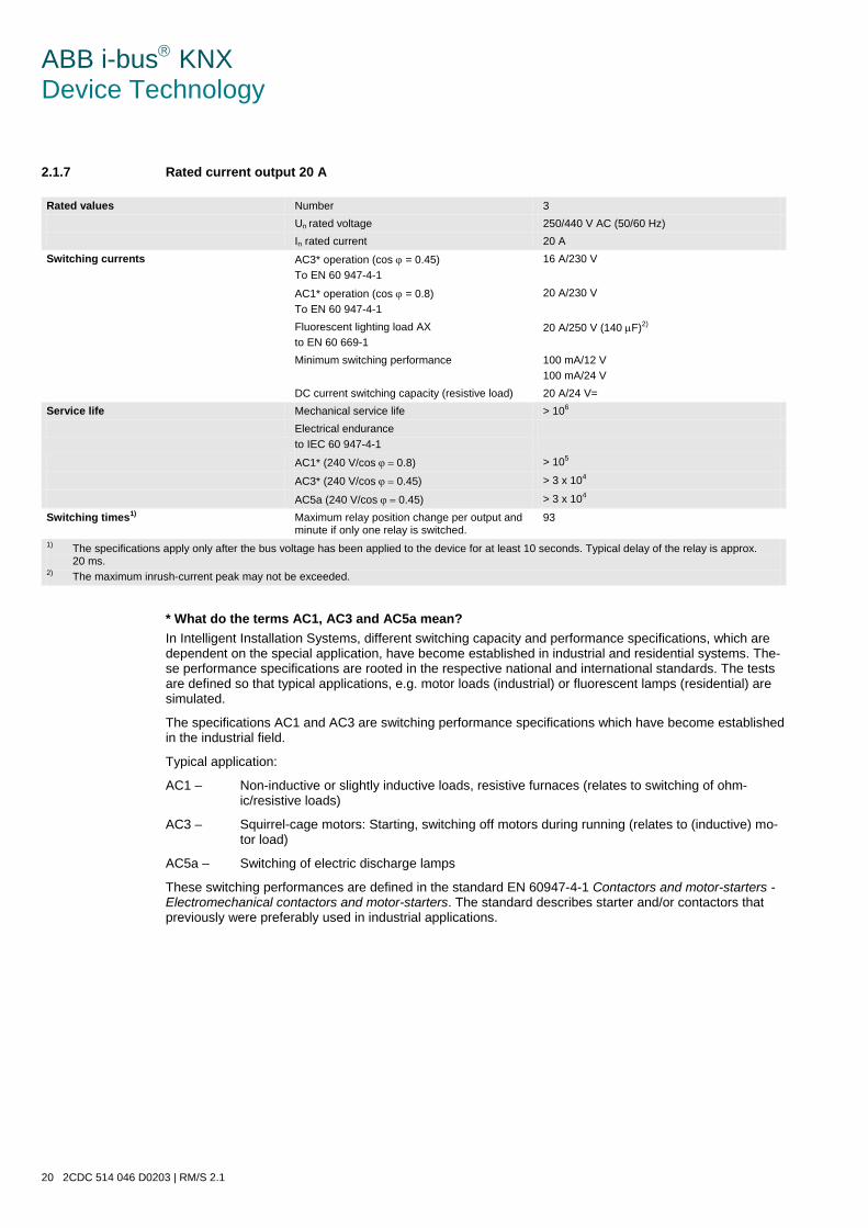
ABB i-bus KNX Device Technology
20 2CDC 514 046 D0203 | RM/S 2.1
2.1.7 Rated current output 20 A
Rated values Number 3 Un rated voltage 250/440 V AC (50/60 Hz) In rated current 20 A Switching currents AC3* operation (cos ϕ = 0.45)
To EN 60 947-4-1 16 A/230 V
AC1* operation (cos ϕ = 0.8) To EN 60 947-4-1
20 A/230 V
Fluorescent lighting load AX to EN 60 669-1
20 A/250 V (140 µF)2)
Minimum switching performance 100 mA/12 V 100 mA/24 V
DC current switching capacity (resistive load) 20 A/24 V= Service life Mechanical service life > 106 Electrical endurance
to IEC 60 947-4-1
AC1* (240 V/cos ϕ = 0.8) > 105
AC3* (240 V/cos ϕ = 0.45) > 3 x 10⁴
AC5a (240 V/cos ϕ = 0.45) > 3 x 10⁴
Switching times1) Maximum relay position change per output and minute if only one relay is switched.
93
1) The specifications apply only after the bus voltage has been applied to the device for at least 10 seconds. Typical delay of the relay is approx. 20 ms.
2) The maximum inrush-current peak may not be exceeded.
* What do the terms AC1, AC3 and AC5a mean? In Intelligent Installation Systems, different switching capacity and performance specifications, which are dependent on the special application, have become established in industrial and residential systems. The-se performance specifications are rooted in the respective national and international standards. The tests are defined so that typical applications, e.g. motor loads (industrial) or fluorescent lamps (residential) are simulated.
The specifications AC1 and AC3 are switching performance specifications which have become established in the industrial field.
Typical application:
AC1 – Non-inductive or slightly inductive loads, resistive furnaces (relates to switching of ohm-ic/resistive loads)
AC3 – Squirrel-cage motors: Starting, switching off motors during running (relates to (inductive) mo-tor load)
AC5a – Switching of electric discharge lamps
These switching performances are defined in the standard EN 60947-4-1 Contactors and motor-starters - Electromechanical contactors and motor-starters. The standard describes starter and/or contactors that previously were preferably used in industrial applications.
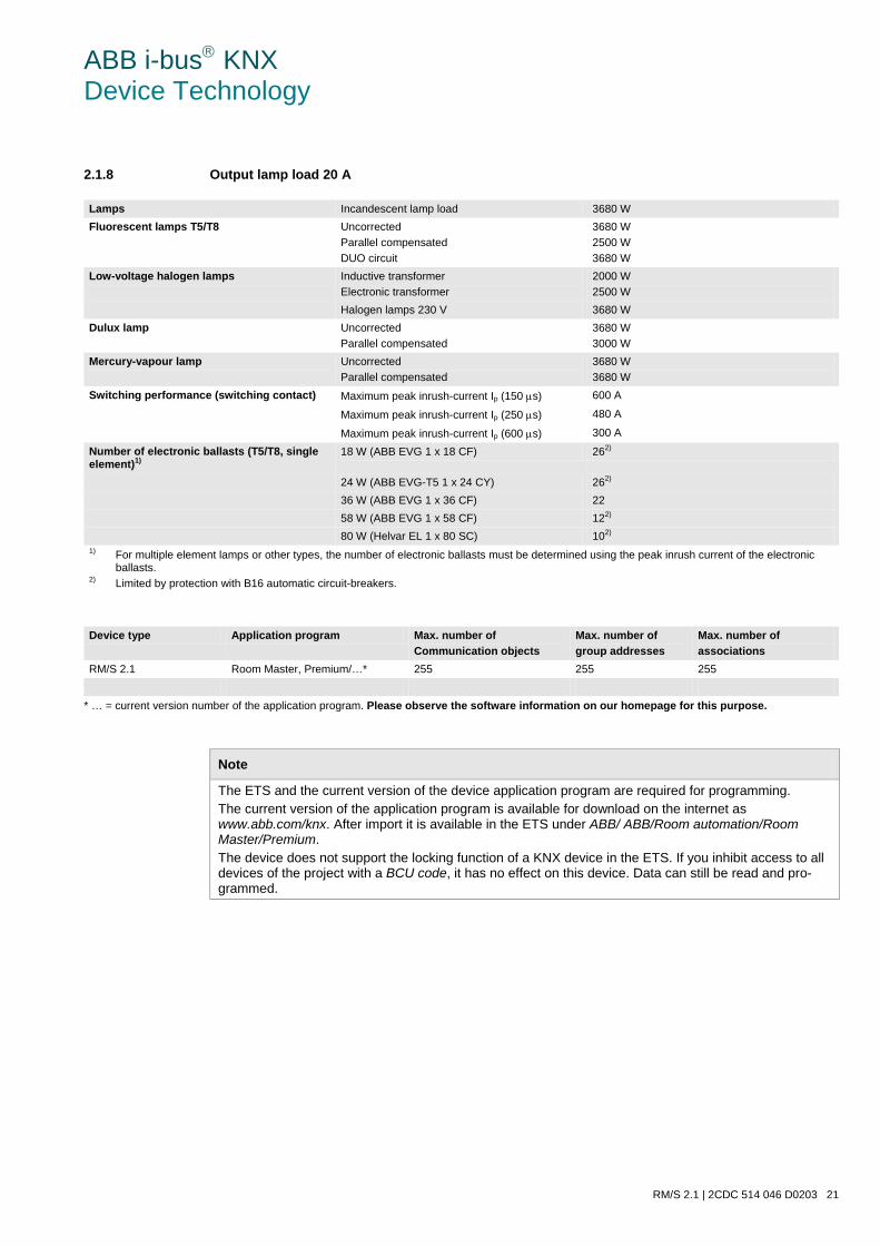
ABB i-bus KNX Device Technology
RM/S 2.1 | 2CDC 514 046 D0203 21
2.1.8 Output lamp load 20 A
Lamps Incandescent lamp load 3680 W Fluorescent lamps T5/T8
Uncorrected Parallel compensated DUO circuit
3680 W 2500 W 3680 W
Low-voltage halogen lamps Inductive transformer Electronic transformer
2000 W 2500 W
Halogen lamps 230 V 3680 W Dulux lamp
Uncorrected Parallel compensated
3680 W 3000 W
Mercury-vapour lamp
Uncorrected Parallel compensated
3680 W 3680 W
Switching performance (switching contact) Maximum peak inrush-current Ip (150 µs) 600 A
Maximum peak inrush-current Ip (250 µs) 480 A
Maximum peak inrush-current Ip (600 µs) 300 A
Number of electronic ballasts (T5/T8, single element)1)
18 W (ABB EVG 1 x 18 CF) 262)
24 W (ABB EVG-T5 1 x 24 CY) 262) 36 W (ABB EVG 1 x 36 CF) 22 58 W (ABB EVG 1 x 58 CF) 122) 80 W (Helvar EL 1 x 80 SC) 102) 1) For multiple element lamps or other types, the number of electronic ballasts must be determined using the peak inrush current of the electronic
ballasts. 2) Limited by protection with B16 automatic circuit-breakers.
Device type Application program Max. number of
Communication objects Max. number of group addresses
Max. number of associations
RM/S 2.1 Room Master, Premium/…* 255 255 255
* … = current version number of the application program. Please observe the software information on our homepage for this purpose.
Note
The ETS and the current version of the device application program are required for programming. The current version of the application program is available for download on the internet as www.abb.com/knx. After import it is available in the ETS under ABB/ ABB/Room automation/Room Master/Premium. The device does not support the locking function of a KNX device in the ETS. If you inhibit access to all devices of the project with a BCU code, it has no effect on this device. Data can still be read and pro-grammed.
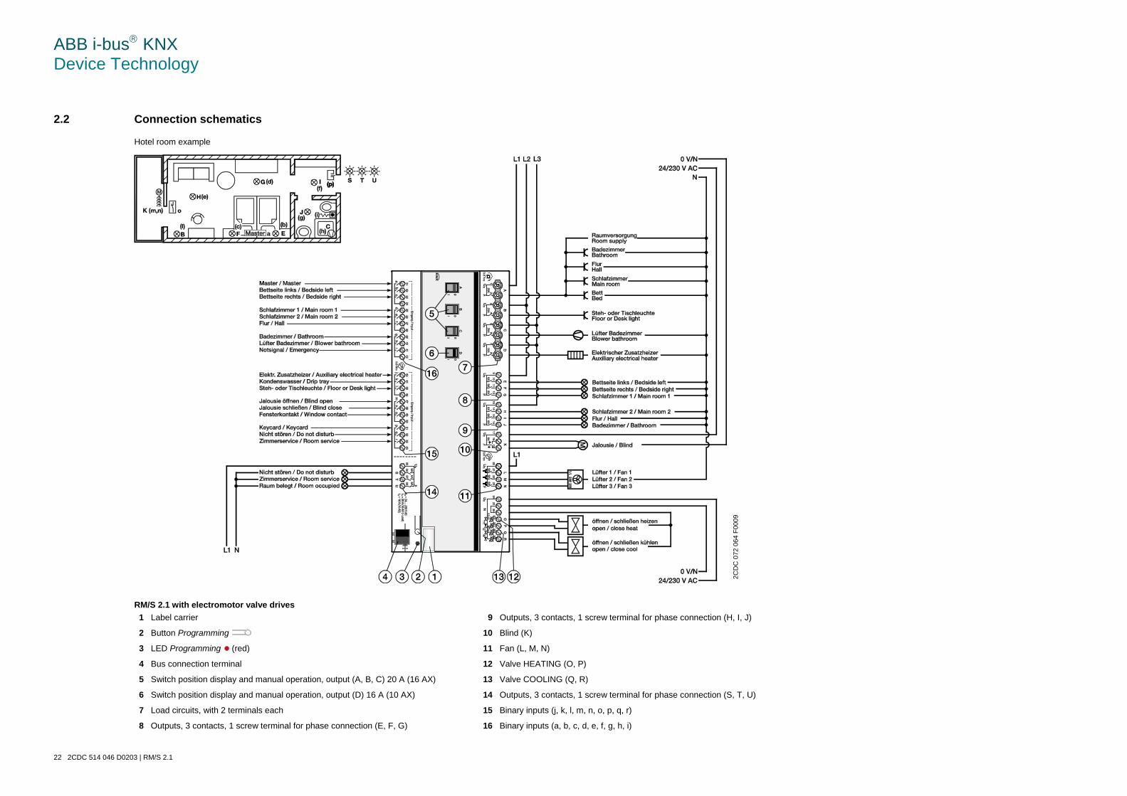
ABB i-bus KNX Device Technology
22 2CDC 514 046 D0203 | RM/S 2.1
2.2 Connection schematics
Hotel room example
RM/S 2.1 with electromotor valve drives 1 Label carrier 9 Outputs, 3 contacts, 1 screw terminal for phase connection (H, I, J)
2 Button Programming 10 Blind (K)
3 LED Programming (red) 11 Fan (L, M, N)
4 Bus connection terminal 12 Valve HEATING (O, P)
5 Switch position display and manual operation, output (A, B, C) 20 A (16 AX) 13 Valve COOLING (Q, R)
6 Switch position display and manual operation, output (D) 16 A (10 AX) 14 Outputs, 3 contacts, 1 screw terminal for phase connection (S, T, U)
7 Load circuits, with 2 terminals each 15 Binary inputs (j, k, l, m, n, o, p, q, r)
8 Outputs, 3 contacts, 1 screw terminal for phase connection (E, F, G) 16 Binary inputs (a, b, c, d, e, f, g, h, i)
2C
DC
072
064
F00
09
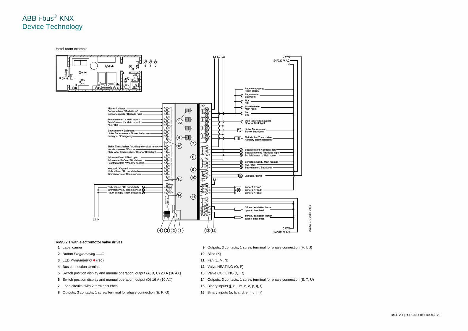
ABB i-bus KNX Device Technology
RM/S 2.1 | 2CDC 514 046 D0203 23
Hotel room example
RM/S 2.1 with electromotor valve drives 1 Label carrier 9 Outputs, 3 contacts, 1 screw terminal for phase connection (H, I, J)
2 Button Programming 10 Blind (K)
3 LED Programming (red) 11 Fan (L, M, N)
4 Bus connection terminal 12 Valve HEATING (O, P)
5 Switch position display and manual operation, output (A, B, C) 20 A (16 AX) 13 Valve COOLING (Q, R)
6 Switch position display and manual operation, output (D) 16 A (10 AX) 14 Outputs, 3 contacts, 1 screw terminal for phase connection (S, T, U)
7 Load circuits, with 2 terminals each 15 Binary inputs (j, k, l, m, n, o, p, q, r)
8 Outputs, 3 contacts, 1 screw terminal for phase connection (E, F, G) 16 Binary inputs (a, b, c, d, e, f, g, h, i)
2CD
C 0
72 0
68 F
0411
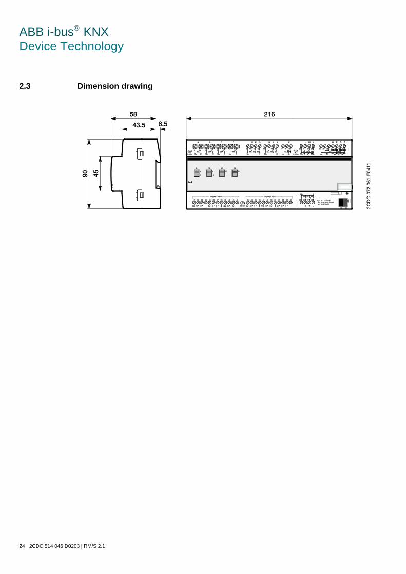
ABB i-bus KNX Device Technology
24 2CDC 514 046 D0203 | RM/S 2.1
2.3 Dimension drawing
2CD
C 0
72 0
61 F
0411
ABB i-bus KNX Device Technology
RM/S 2.1 | 2CDC 514 046 D0203 25
2.4 Assembly and installation
The RM/S 2.1 is a modular installation device for quick installation in the distribution board on 35 mm mounting rails to DIN EN 60 715.
The mounting position can be selected as required.
The electrical connection is implemented using screw terminals. The connection to the bus is implemented using the supplied bus connection terminal. The terminal assignment is located on the housing.
The device is ready for operation after connection to the bus voltage.
Accessibility of the devices for the purpose of operation, testing, visual inspection, maintenance and repair must be provided compliant to DIN VDE 0100-520.
Commissioning requirements In order to commission the device, a PC with ETS as well as an interface to the ABB i-bus®, e.g. via a KNX interface, is required.
The device is ready for operation after connection to the bus voltage. No additional auxiliary voltage is re-quired.
Important
The maximum permissible current of a KNX line may not be exceeded. During planning and installation ensure that the KNX line is correctly dimensioned. The device features a maximum current consumption of 24 mA (Fan-In 2).
The installation and commissioning may only be carried out by electrical specialists. The appropriate norms, guidelines, regulations and specifications for your country should be observed when planning and setting up electrical installations and security systems for intrusion and fire detection.
• Protect the device from damp, dirt and damage during transport, storage and operation.
• Only operate the device within the specified technical data limits!
• The device should only be operated in an enclosed housing (distribution board)!
• The voltage supply to the device must be switched off, before mounting work is performed.
Danger In order to avoid dangerous touch voltages, which originate through feedback from differing phase con-ductors, all-pole disconnection must be observed when extending or modifying the electrical connec-tions.
ABB i-bus KNX Device Technology
26 2CDC 514 046 D0203 | RM/S 2.1
Supplied state The device is supplied with the physical address 15.15.255. The application program is preloaded. It is therefore only necessary to load group addresses and parameters during commissioning.
However, the complete application program can be reloaded if required. A longer downtime may result if the application program is changed or after a discharge.
Assignment of the physical address The assignment and programming of the physical address is carried out in the ETS.
The device features a button for assignment of the physical device address. The red LED lights up, after the button has been pushed. It switches off as soon as the ETS has assigned the physical ad-dress or the button is pressed again.
Download response Depending on the PC which is used, the progress bar for the download may take up to one and a half minutes, before it appears, due to the complexity of the device.
Cleaning If devices become dirty, they can be cleaned using a dry cloth or a cloth dampened with a soapy solution. Corrosive agents or solutions should never be used.
Maintenance The device is maintenance-free. No repairs should be carried out by unauthorised personnel if damage occurs, e.g. during transport and/or storage.
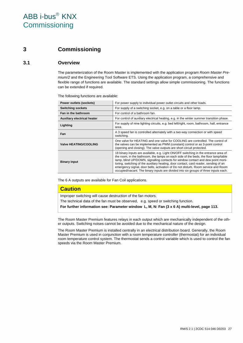
ABB i-bus KNX Commissioning
RM/S 2.1 | 2CDC 514 046 D0203 27
3 Commissioning
3.1 Overview
The parameterization of the Room Master is implemented with the application program Room Master Pre-mium/2 and the Engineering Tool Software ETS. Using the application program, a comprehensive and flexible range of functions are available. The standard settings allow simple commissioning. The functions can be extended if required.
The following functions are available:
Power outlets (sockets) For power supply to individual power outlet circuits and other loads.
Switching sockets For supply of a switching socket, e.g. on a table or a floor lamp.
Fan in the bathroom For control of a bathroom fan.
Auxiliary electrical heater For control of auxiliary electrical heating, e.g. in the winter summer transition phase.
Lighting For supply of nine lighting circuits, e.g. bed left/right, room, bathroom, hall, entrance area.
Fan A 3 speed fan is controlled alternately with a two-way connection or with speed switching.
Valve HEATING/COOLING One valve for HEATING and one valve for COOLING are controlled. The control of the valves can be implemented as PWM (constant) control or as 3-point control (opening and closing). The valve outputs are short circuit protected.
Binary input
18 binary inputs are available, e.g. Light ON/OFF switching in the entrance area of the room, in the bathroom, the lamps on each side of the beds, the floor lamp/table lamp, blind UP/DOWN, signalling contacts for window contact and dew point moni-toring, switching of the auxiliary heating, door contact, card reader, sending of an emergency signal, door bells, activation of Do not disturb, Room service and Room occupied/vacant. The binary inputs are divided into six groups of three inputs each.
The 6 A outputs are available for Fan Coil applications.
Caution Improper switching will cause destruction of the fan motors. The technical data of the fan must be observed, e.g. speed or switching function. For further information see: Parameter windowL, M, N: Fan (3 x 6 A) multi-level, page 113.
The Room Master Premium features relays in each output which are mechanically independent of the oth-er outputs. Switching noises cannot be avoided due to the mechanical nature of the design.
The Room Master Premium is installed centrally in an electrical distribution board. Generally, the Room Master Premium is used in conjunction with a room temperature controller (thermostat) for an individual room temperature control system. The thermostat sends a control variable which is used to control the fan speeds via the Room Master Premium.
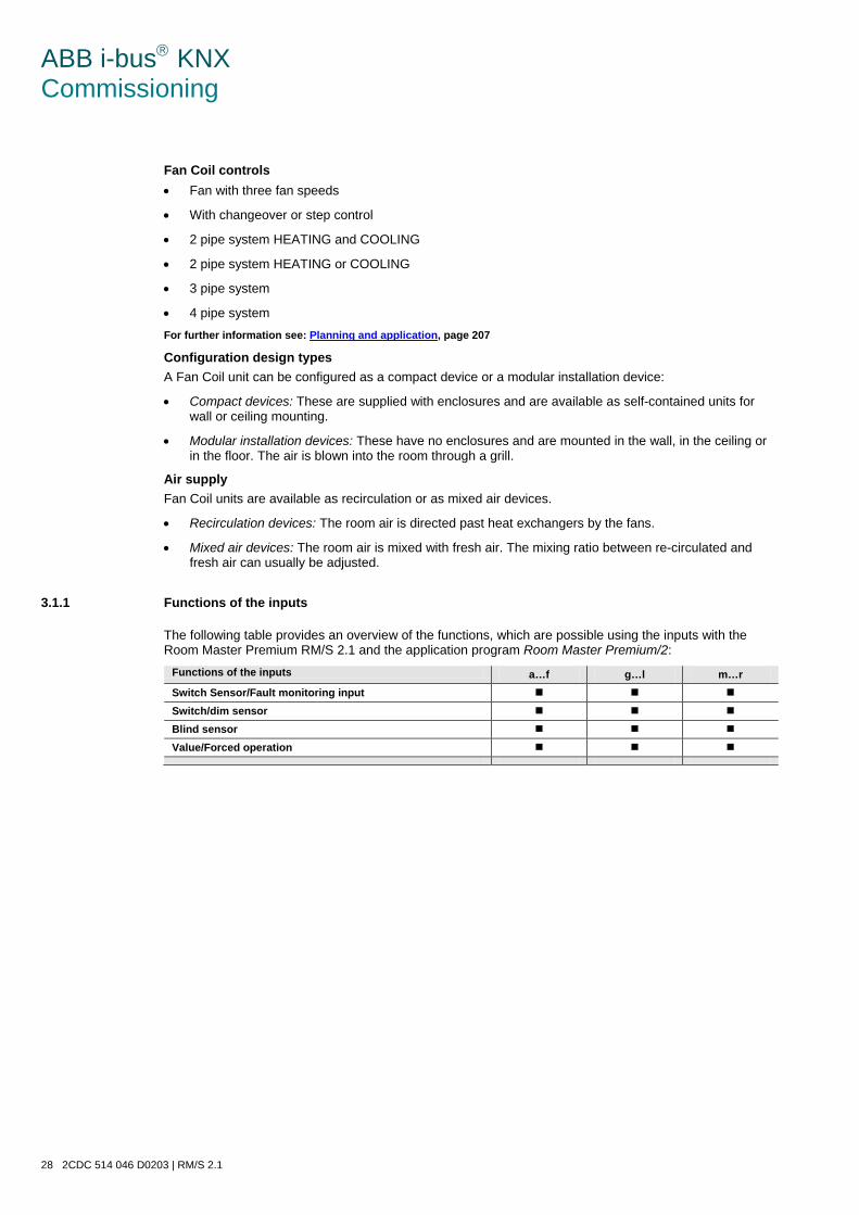
ABB i-bus KNX Commissioning
28 2CDC 514 046 D0203 | RM/S 2.1
Fan Coil controls • Fan with three fan speeds
• With changeover or step control
• 2 pipe system HEATING and COOLING
• 2 pipe system HEATING or COOLING
• 3 pipe system
• 4 pipe system For further information see: Planning and application, page 207
Configuration design types A Fan Coil unit can be configured as a compact device or a modular installation device:
• Compact devices: These are supplied with enclosures and are available as self-contained units for wall or ceiling mounting.
• Modular installation devices: These have no enclosures and are mounted in the wall, in the ceiling or in the floor. The air is blown into the room through a grill.
Air supply Fan Coil units are available as recirculation or as mixed air devices.
• Recirculation devices: The room air is directed past heat exchangers by the fans.
• Mixed air devices: The room air is mixed with fresh air. The mixing ratio between re-circulated and fresh air can usually be adjusted.
3.1.1 Functions of the inputs
The following table provides an overview of the functions, which are possible using the inputs with the Room Master Premium RM/S 2.1 and the application program Room Master Premium/2:
Functions of the inputs a…f g…l m…r Switch Sensor/Fault monitoring input Switch/dim sensor Blind sensor Value/Forced operation
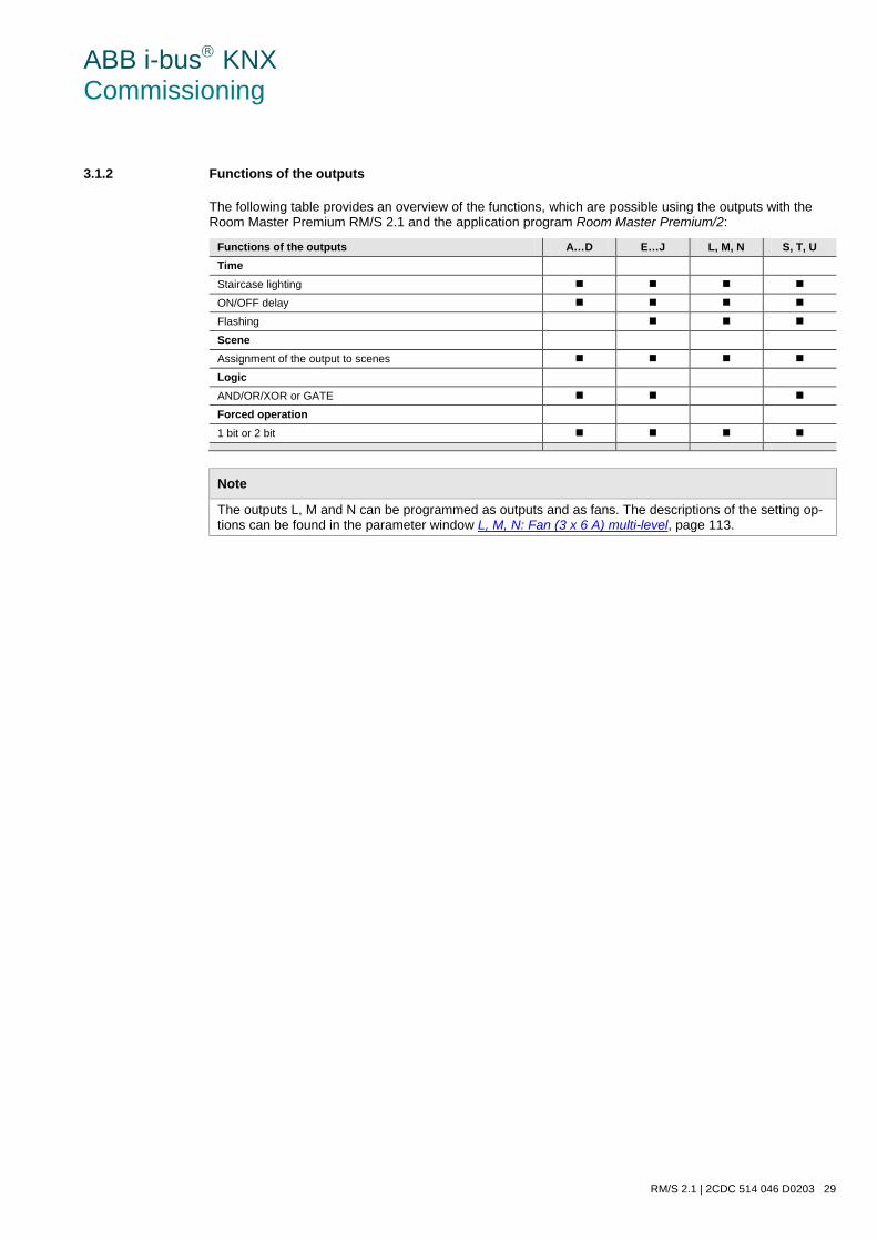
ABB i-bus KNX Commissioning
RM/S 2.1 | 2CDC 514 046 D0203 29
3.1.2 Functions of the outputs
The following table provides an overview of the functions, which are possible using the outputs with the Room Master Premium RM/S 2.1 and the application program Room Master Premium/2:
Functions of the outputs A…D E…J L, M, N S, T, U Time Staircase lighting ON/OFF delay Flashing Scene Assignment of the output to scenes Logic AND/OR/XOR or GATE Forced operation 1 bit or 2 bit
Note
The outputs L, M and N can be programmed as outputs and as fans. The descriptions of the setting op-tions can be found in the parameter window L, M, N: Fan (3 x 6 A) multi-level, page 113.
ABB i-bus KNX Commissioning
30 2CDC 514 046 D0203 | RM/S 2.1
3.2 Parameters
The parameterization of the Room Master is implemented using the Engineering Tool Software ETS. The application program is available in the ETS at ABB/Room automation/Room Master/Premium.
The following chapter describes the parameters of the RM/S 2.1 using the parameter windows. The pa-rameter window features a dynamic structure, so that further parameters may be enabled depending on the parameterization and the function of the outputs.
The default values of the parameters are underlined, e.g.:
Options: yes no
Note
In this chapter, the parameters are explained using the default settings. An overview of the pre-configured settings in conjunction with the room states can be found in the chapter Preconfiguration, page 265.
Note
The device features several inputs/outputs. As the functions are identical for all inputs/outputs, they will only be explained using input/output A as an example.
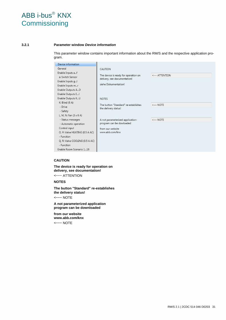
ABB i-bus KNX Commissioning
RM/S 2.1 | 2CDC 514 046 D0203 31
3.2.1 Parameter window Device information
This parameter window contains important information about the RM/S and the respective application pro-gram.
CAUTION
The device is ready for operation on delivery, see documentation! <−−− ATTENTION
NOTES
The button "Standard" re-establishes the delivery status! <−−− NOTE
A not parameterized application program can be downloaded
from our website www.abb.com/knx <−−− NOTE
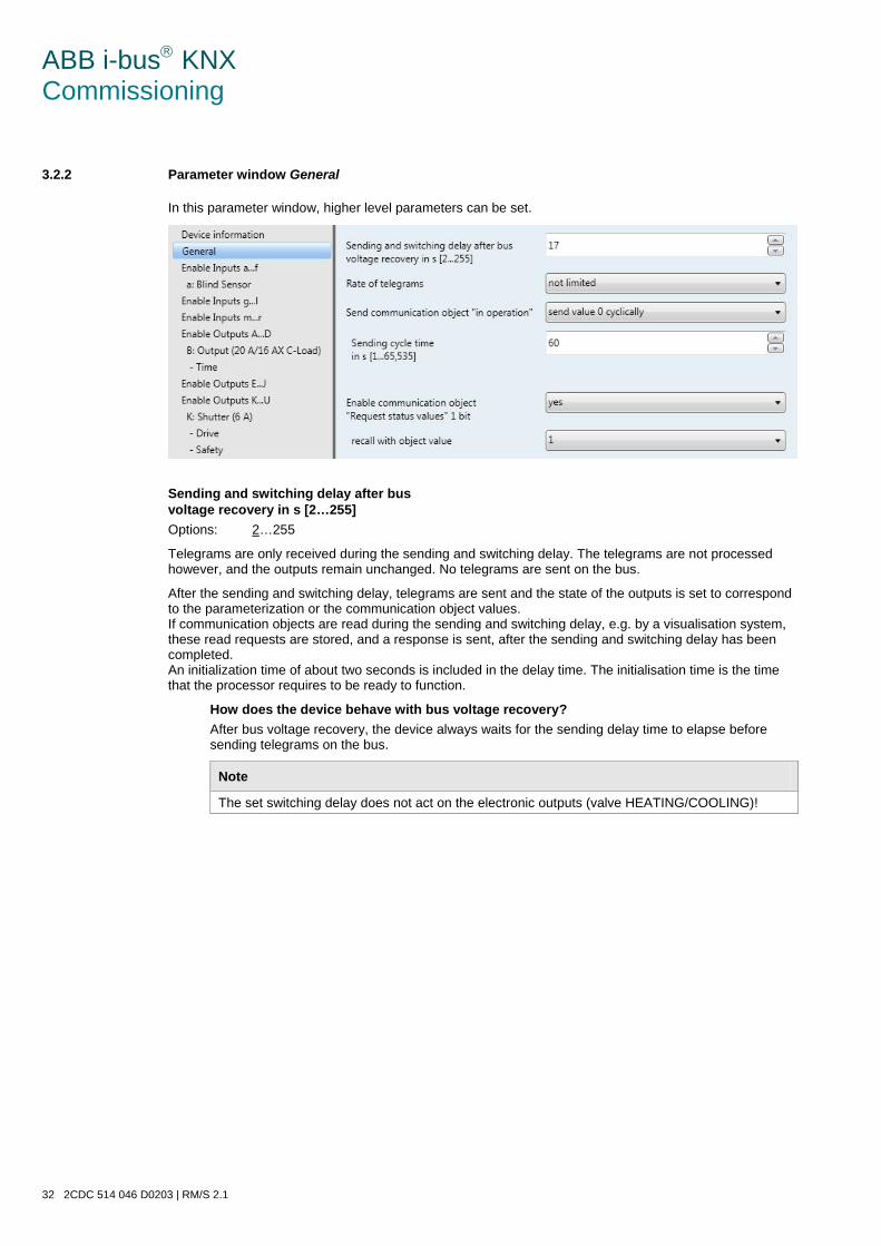
ABB i-bus KNX Commissioning
32 2CDC 514 046 D0203 | RM/S 2.1
3.2.2 Parameter window General
In this parameter window, higher level parameters can be set.
Sending and switching delay after bus voltage recovery in s [2…255] Options: 2…255
Telegrams are only received during the sending and switching delay. The telegrams are not processed however, and the outputs remain unchanged. No telegrams are sent on the bus.
After the sending and switching delay, telegrams are sent and the state of the outputs is set to correspond to the parameterization or the communication object values. If communication objects are read during the sending and switching delay, e.g. by a visualisation system, these read requests are stored, and a response is sent, after the sending and switching delay has been completed. An initialization time of about two seconds is included in the delay time. The initialisation time is the time that the processor requires to be ready to function.
How does the device behave with bus voltage recovery? After bus voltage recovery, the device always waits for the sending delay time to elapse before sending telegrams on the bus.
Note
The set switching delay does not act on the electronic outputs (valve HEATING/COOLING)!
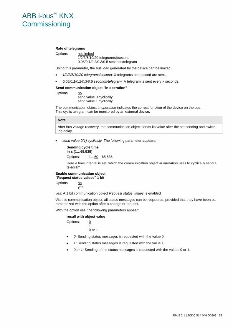
ABB i-bus KNX Commissioning
RM/S 2.1 | 2CDC 514 046 D0203 33
Rate of telegrams Options: not limited
1/2/3/5/10/20 telegram(s)/second 0.05/0.1/0.2/0.3/0.5 seconds/telegram
Using this parameter, the bus load generated by the device can be limited.
• 1/2/3/5/10/20 telegrams/second: X telegrams per second are sent.
• 0.05/0.1/0.2/0.3/0.5 seconds/telegram: A telegram is sent every x seconds.
Send communication object "in operation" Options: no
send value 0 cyclically send value 1 cyclically
The communication object in operation indicates the correct function of the device on the bus. This cyclic telegram can be monitored by an external device.
Note
After bus voltage recovery, the communication object sends its value after the set sending and switch-ing delay.
• send value 0(1) cyclically: The following parameter appears:
Sending cycle time in s [1…65,535] Options: 1…60…65,535
Here a time interval is set, which the communication object in operation uses to cyclically send a telegram.
Enable communication object "Request status values" 1 bit Options: no
yes
yes: A 1 bit communication object Request status values is enabled.
Via this communication object, all status messages can be requested, provided that they have been pa-rameterized with the option after a change or request.
With the option yes, the following parameters appear:
recall with object value Options: 0
1 0 or 1
• 0: Sending status messages is requested with the value 0.
• 1: Sending status messages is requested with the value 1.
• 0 or 1: Sending of the status messages is requested with the values 0 or 1.
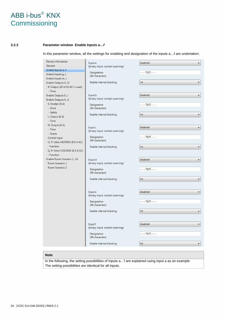
ABB i-bus KNX Commissioning
34 2CDC 514 046 D0203 | RM/S 2.1
3.2.3 Parameter windowEnable Inputs a…f
In this parameter window, all the settings for enabling and designation of the inputs a…f are undertaken.
Note In the following, the setting possibilities of Inputs a…f are explained using input a as an example. The setting possibilities are identical for all inputs.
ABB i-bus KNX Commissioning
RM/S 2.1 | 2CDC 514 046 D0203 35
Input a (binary input, contact scanning) Option: disabled
Switch Sensor/Fault monitoring input Switch/dim sensor Blind sensor Value/Forced operation
The operating mode of the input is set with this parameter. The respective parameter window a: xxx also becomes visible with the selection of an operating mode.
Designation Options: - - - TEXT - - -
With this parameter, it is possible to enter a text of up to 40 characters in length for identification in the ETS.
Note
The text which is entered is used to provide help, in order to obtain an overview of the inputs when they are fully assigned and to indicate the function assigned to the input. The text is purely for informative purposes and has no further function.
Enable internal blocking Options: no
yes
This parameter defines whether a binary input can or cannot be internally inhibited. If an internal block is called, the binary input is physically disabled. Pressing a connected button/switch as well as incoming tel-egrams on communication object Event 0/1 started are ignored.
This parameterization option enables the establishment of a blocking mask for all 18 binary inputs. This blocking mask may also be called at every room state. It is thus possible to inhibit or enable the binary in-puts using this mask when this room state is called.
• no: The input cannot be inhibited internally nor via the communication object Block.
• yes: The input can be blocked internally.
Inputs b…f The device features several inputs. However, as the functions for all inputs are identical, only the functions of input a will be described.
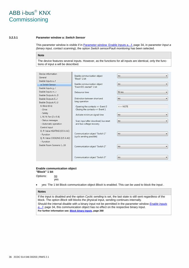
ABB i-bus KNX Commissioning
36 2CDC 514 046 D0203 | RM/S 2.1
3.2.3.1 Parameter window a: Switch Sensor
This parameter window is visible if in Parameter windowEnable Inputs a…f, page 34, in parameter Input a (binary input, contact scanning), the option Switch sensor/Fault monitoring has been selected.
Note
The device features several inputs. However, as the functions for all inputs are identical, only the func-tions of input a will be described.
Enable communication object "Block" 1 bit Options: no
yes
• yes: The 1 bit Block communication object Block is enabled. This can be used to block the input .
Notes If the input is disabled and the option Cyclic sending is set, the last state is still sent regardless of the block. The option Block still blocks the physical input, sending continues internally. Should the internal disable with a binary input not be permitted in the parameter window Enable Inputs a…f, page 34, this communication object has no effect on the respective binary input. For further information see: Block binary inputs, page 268
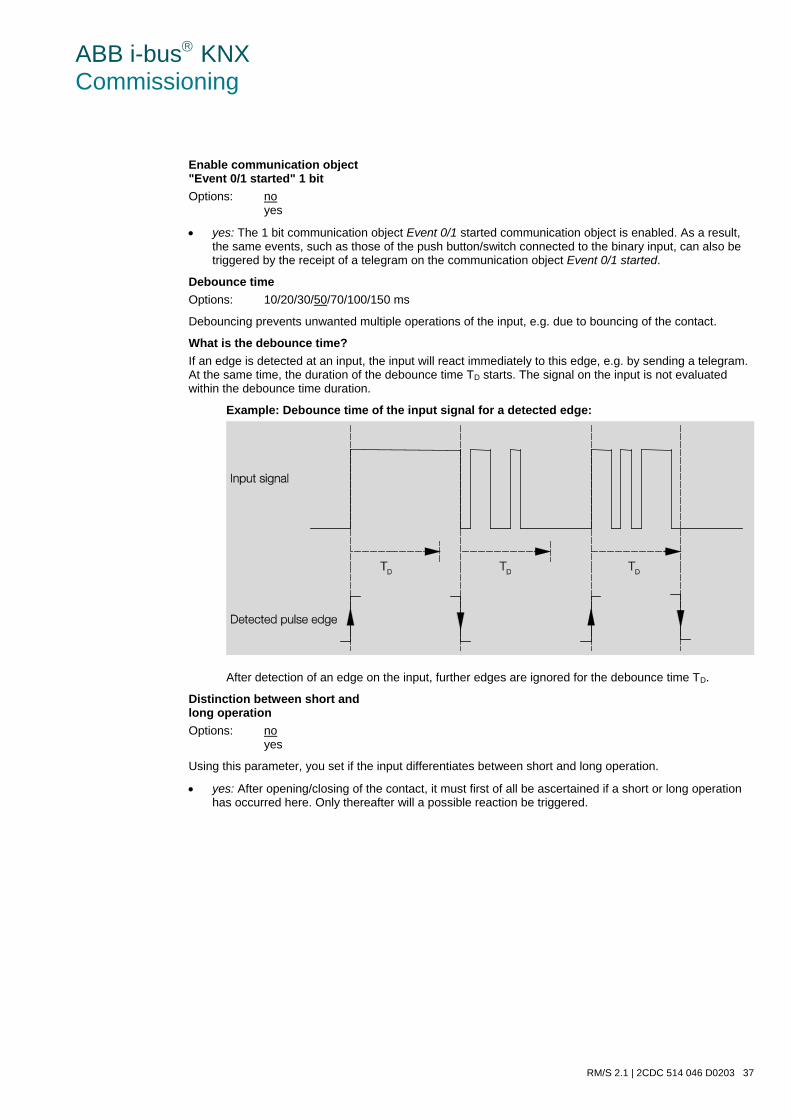
ABB i-bus KNX Commissioning
RM/S 2.1 | 2CDC 514 046 D0203 37
Enable communication object "Event 0/1 started" 1 bit Options: no
yes
• yes: The 1 bit communication object Event 0/1 started communication object is enabled. As a result, the same events, such as those of the push button/switch connected to the binary input, can also be triggered by the receipt of a telegram on the communication object Event 0/1 started.
Debounce time Options: 10/20/30/50/70/100/150 ms
Debouncing prevents unwanted multiple operations of the input, e.g. due to bouncing of the contact.
What is the debounce time? If an edge is detected at an input, the input will react immediately to this edge, e.g. by sending a telegram. At the same time, the duration of the debounce time TD starts. The signal on the input is not evaluated within the debounce time duration.
Example: Debounce time of the input signal for a detected edge:
After detection of an edge on the input, further edges are ignored for the debounce time TD.
Distinction between short and long operation Options: no
yes
Using this parameter, you set if the input differentiates between short and long operation.
• yes: After opening/closing of the contact, it must first of all be ascertained if a short or long operation has occurred here. Only thereafter will a possible reaction be triggered.
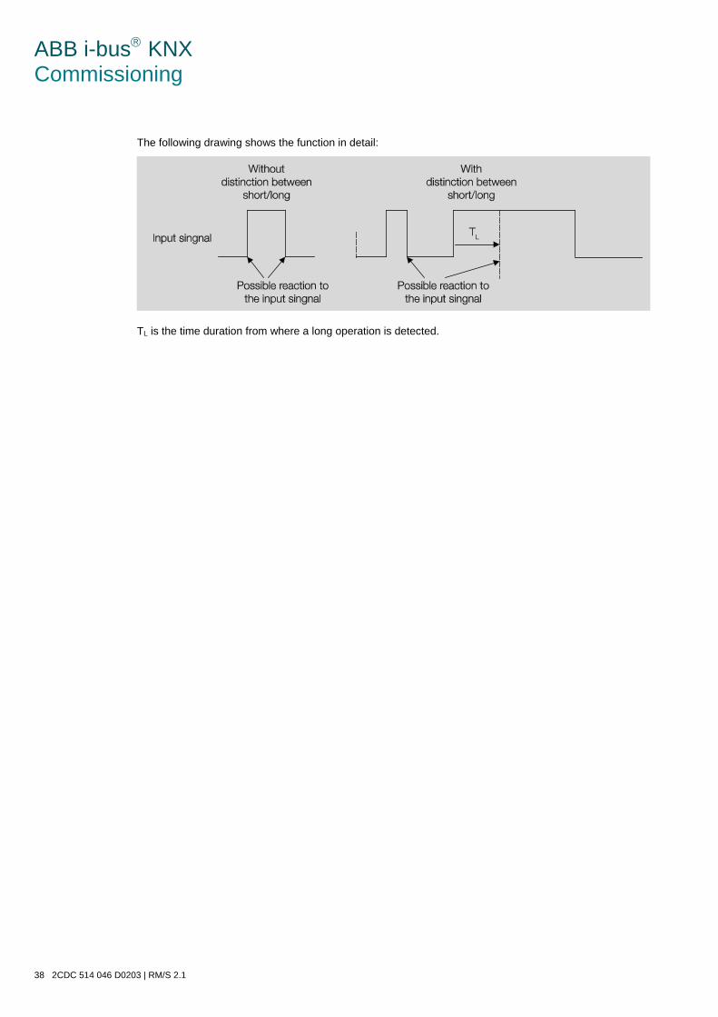
ABB i-bus KNX Commissioning
38 2CDC 514 046 D0203 | RM/S 2.1
The following drawing shows the function in detail:
TL is the time duration from where a long operation is detected.
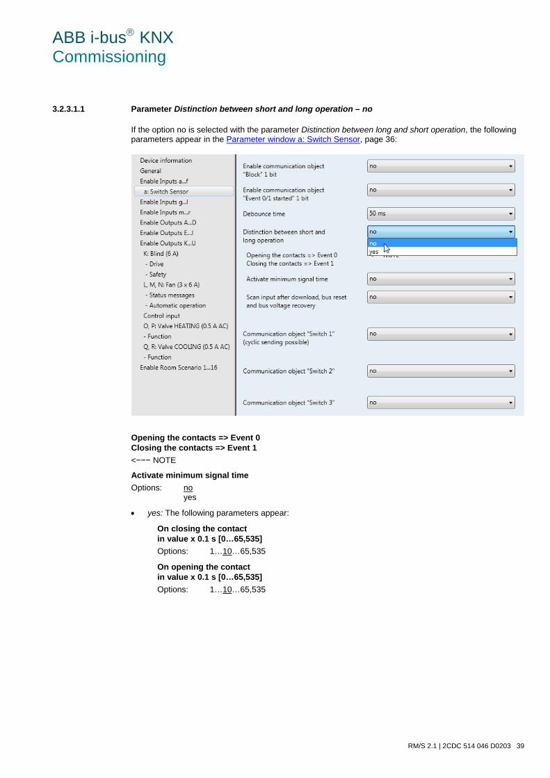
ABB i-bus KNX Commissioning
RM/S 2.1 | 2CDC 514 046 D0203 39
3.2.3.1.1 Parameter Distinction between short and long operation – no
If the option no is selected with the parameter Distinction between long and short operation, the following parameters appear in the Parameter window a: Switch Sensor, page 36:
Opening the contacts => Event 0 Closing the contacts => Event 1 <−−− NOTE
Activate minimum signal time Options: no
yes
• yes: The following parameters appear:
On closing the contact in value x 0.1 s [0…65,535] Options: 1…10…65,535
On opening the contact in value x 0.1 s [0…65,535] Options: 1…10…65,535
ABB i-bus KNX Commissioning
40 2CDC 514 046 D0203 | RM/S 2.1
What is the minimum signal time? In contrast to the debounce time, a telegram is only sent after the minimum signal duration has elapsed.
The individual functions are:
If an edge is detected on the input, the minimum signal duration will commence. No telegram is sent on the bus at this time. The signal on the input is observed within the minimum signal duration. If a further edge appears at the input during the minimum signal duration, it will be interpreted as a new operation, and the minimum signal duration restarts. If no further edges occur after the start of the minimum signal duration, a telegram is sent on the bus, after the minimum signal duration has timed out.
Example: Minimum signal duration of the input signal for a detected edge:
In only two cases, no further edge changes occur within the minimum signal duration TM after a change of edge. For this reason, only both of these are detected as valid.
Scan input after download, bus reset and bus voltage recovery Options: no
yes
• no: The object value is not scanned after a download, bus reset and bus voltage recovery.
• yes: The object value is scanned after a download, bus reset and bus voltage recovery: The following parameter appears.
ABB i-bus KNX Commissioning
RM/S 2.1 | 2CDC 514 046 D0203 41
Inactive wait state after bus voltage recovery in s [0…30,000] Options: 0…30,000
Here the waiting time after a bus voltage recovery is set. After the waiting time has elapsed the state on the input terminals is scanned. The input reacts as if the state on the input terminals has just changed.
Note
The inactive waiting time does not add to the actual, adjustable send delay time. This can be set separately.
Communication object "Switch 1" (cyclic sending possible) Options: no
yes
• yes: The communication object Switch 1 appears. The following parameters appear:
Reaction with event 0 Options: ON
OFF TOGGLE no reaction terminate cyclic sending
Reaction with event 1 Options: ON
OFF TOGGLE no reaction terminate cyclic sending
The behaviour of the communication object is determined here. If the option yes has been selected with the parameter Distinction between short and long operation, the reaction occurs with a short or long operation. With the option no it occurs with each edge change.
Important
If the option terminate cyclic sending is set, it is important to note that this is only effective if the option yes has only been selected in the following parameter Cyclic sending.
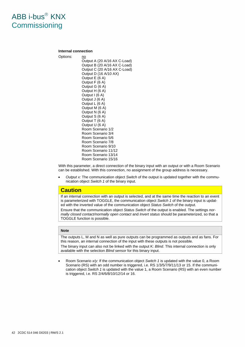
ABB i-bus KNX Commissioning
42 2CDC 514 046 D0203 | RM/S 2.1
Internal connection Options: no
Output A (20 A/16 AX C-Load) Output B (20 A/16 AX C-Load) Output C (20 A/16 AX C-Load) Output D (16 A/10 AX) Output E (6 A) Output F (6 A) Output G (6 A) Output H (6 A) Output I (6 A) Output J (6 A) Output L (6 A) Output M (6 A) Output N (6 A) Output S (6 A) Output T (6 A) Output U (6 A) Room Scenario 1/2 Room Scenario 3/4 Room Scenario 5/6 Room Scenario 7/8 Room Scenario 9/10 Room Scenario 11/12 Room Scenario 13/14 Room Scenario 15/16
With this parameter, a direct connection of the binary input with an output or with a Room Scenario can be established. With this connection, no assignment of the group address is necessary.
• Output x: The communication object Switch of the output is updated together with the commu-nication object Switch 1 of the binary input.
Caution If an internal connection with an output is selected, and at the same time the reaction to an event is parameterized with TOGGLE, the communication object Switch 1 of the binary input is updat-ed with the inverted value of the communication object Status Switch of the output. Ensure that the communication object Status Switch of the output is enabled. The settings nor-mally closed contact/normally open contact and Invert status should be parameterized, so that a TOGGLE function is possible.
Note The outputs L, M and N as well as pure outputs can be programmed as outputs and as fans. For this reason, an internal connection of the input with these outputs is not possible. The binary input can also not be linked with the output K: Blind. This internal connection is only available with the selection Blind sensor for this binary input.
• Room Scenario x/y: If the communication object Switch 1 is updated with the value 0, a Room
Scenario (RS) with an odd number is triggered, i.e. RS 1/3/5/7/9/11/13 or 15. If the communi-cation object Switch 1 is updated with the value 1, a Room Scenario (RS) with an even number is triggered, i.e. RS 2/4/6/8/10/12/14 or 16.
ABB i-bus KNX Commissioning
RM/S 2.1 | 2CDC 514 046 D0203 43
Cyclic sending Options: no
yes
What is cyclic sending? Cyclic sending enables the communication object Switch to send automatically at a fixed interval. If cyclic sending is only carried out for a specific object value (ON or OFF), this condition refers to the value of the communication object. It is therefore possible in principle to start cyclic sending by sending a value to the communication object Switch. As this behaviour is unwanted, the flags Write and Update of the communication object are deleted in the preliminary setting, so that they cannot be changed via the bus. If this functionality is required irrespectively, these flags should be set ac-cordingly. When the Switch communication object changes and after bus recovery (after the send delay time has elapsed), the communication object value is sent immediately on the bus, and the transmission cycle time restarts.
• yes: The following parameters appear:
Telegram repeated every … in s [1…65,535] Options: 1…60…65,535
The send cycle time describes the time used between two cyclically sent telegrams.
on object value Options: 1
0 0 or 1
• 1: The communication object value is sent cyclically with 1.
• 0: The communication object value is sent cyclically with 0.
• 0 or 1: The communication object values 0 and 1 are sent cyclically.
Communication object “Switch 2”
Communication object “Switch 3” Options: no
yes
• yes: The communication object Switch X becomes visible. The following parameters appear:
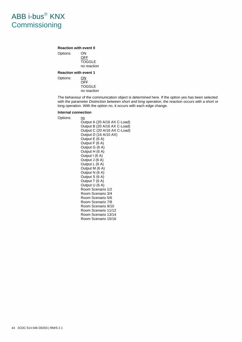
ABB i-bus KNX Commissioning
44 2CDC 514 046 D0203 | RM/S 2.1
Reaction with event 0 Options: ON
OFF TOGGLE no reaction
Reaction with event 1 Options: ON
OFF TOGGLE no reaction
The behaviour of the communication object is determined here. If the option yes has been selected with the parameter Distinction between short and long operation, the reaction occurs with a short or long operation. With the option no, it occurs with each edge change.
Internal connection Options: no
Output A (20 A/16 AX C-Load) Output B (20 A/16 AX C-Load) Output C (20 A/16 AX C-Load) Output D (16 A/10 AX) Output E (6 A) Output F (6 A) Output G (6 A) Output H (6 A) Output I (6 A) Output J (6 A) Output L (6 A) Output M (6 A) Output N (6 A) Output S (6 A) Output T (6 A) Output U (6 A) Room Scenario 1/2 Room Scenario 3/4 Room Scenario 5/6 Room Scenario 7/8 Room Scenario 9/10 Room Scenario 11/12 Room Scenario 13/14 Room Scenario 15/16
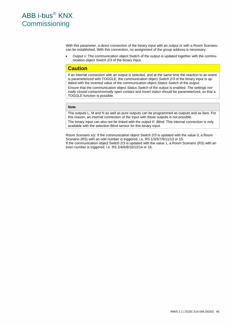
ABB i-bus KNX Commissioning
RM/S 2.1 | 2CDC 514 046 D0203 45
With this parameter, a direct connection of the binary input with an output or with a Room Scenario can be established. With this connection, no assignment of the group address is necessary.
• Output x: The communication object Switch of the output is updated together with the commu-nication object Switch 2/3 of the binary input.
Caution If an internal connection with an output is selected, and at the same time the reaction to an event is parameterized with TOGGLE, the communication object Switch 2/3 of the binary input is up-dated with the inverted value of the communication object Status Switch of the output. Ensure that the communication object Status Switch of the output is enabled. The settings nor-mally closed contact/normally open contact and Invert status should be parameterized, so that a TOGGLE function is possible.
Note The outputs L, M and N as well as pure outputs can be programmed as outputs and as fans. For this reason, an internal connection of the input with these outputs is not possible. The binary input can also not be linked with the output K: Blind. This internal connection is only available with the selection Blind sensor for this binary input.
Room Scenario x/y: If the communication object Switch 2/3 is updated with the value 0, a Room Scenario (RS) with an odd number is triggered, i.e. RS 1/3/5/7/9/11/13 or 15. If the communication object Switch 2/3 is updated with the value 1, a Room Scenario (RS) with an even number is triggered, i.e. RS 2/4/6/8/10/12/14 or 16.
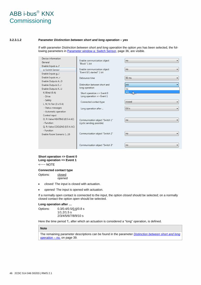
ABB i-bus KNX Commissioning
46 2CDC 514 046 D0203 | RM/S 2.1
3.2.3.1.2 Parameter Distinction between short and long operation – yes
If with parameter Distinction between short and long operation the option yes has been selected, the fol-lowing parameters in Parameter window a: Switch Sensor, page 36, are visible.
Short operation => Event 0 Long operation => Event 1 <−−− NOTE
Connected contact type Options: closed
opened
• closed: The input is closed with actuation.
• opened: The input is opened with actuation.
If a normally open contact is connected to the input, the option closed should be selected; on a normally closed contact the option open should be selected.
Long operation after … Options: 0.3/0.4/0.5/0.6/0.8 s
1/1.2/1.5 s 2/3/4/5/6/7/8/9/10 s
Here the time period TL after which an actuation is considered a “long” operation, is defined.
Note
The remaining parameter descriptions can be found in the parameter Distinction between short and long operation – no, on page 39.
ABB i-bus KNX Commissioning
RM/S 2.1 | 2CDC 514 046 D0203 47
3.2.3.1.3 Special function Fault monitoring input
Note
For the operating mode Fault monitoring input, the options must be adapted in comparison to the stand-ard settings. The options for Fault monitoring mode are listed separately in the following. In this chapter, only the parameters, which are relevant for optimum Fault monitoring input performance are listed. All descriptions of the parameter should be taken from Parameter window a: Switch Sensor page 36.
Debounce time Options: 10/20/30/50/70/100/150 ms
Fault monitoring option: 50 ms
Distinction between short and long operation Options: no
yes
Fault monitoring option: no
Activate minimum signal time Options: no
yes
Fault monitoring option: yes
On closing the contact in value x 0.1 s [1…65,535] Options: 1…10…65,535
Fault monitoring option: 2
On opening the contact in value x 0.1 s [1…65,535] Options: 1…10…65,535
Fault monitoring option: 2
Note
Depending on the system type, a minimum signal duration of two seconds should be set. With the eval-uation, for example, of coupling switches, generator switches or incoming circuit-breakers from switch-gear systems, a smaller minimum signal duration of 100 ms for example, may be necessary. It is essential to co-ordinate the switching times with the operator! Smaller signal/switch times may be required depending on the system.
ABB i-bus KNX Commissioning
48 2CDC 514 046 D0203 | RM/S 2.1
Scan input after download, bus reset and bus voltage recovery Options: no
yes
Fault monitoring option: no
Inactive wait state after bus voltage recovery in s [0…30,000] Options: 0…30,000
Fault monitoring option: 0
Communication object "Switch 1" (cyclic sending possible) Options: no
yes
Fault monitoring option: yes
Reaction with event 0 Options: ON
OFF TOGGLE no reaction End cyclic sending
Fault monitoring option: partly adjustable
Reaction with event 1 Options: ON
OFF TOGGLE no reaction End cyclic sending
Fault monitoring option: partly adjustable
Internal connection Options: no
Output x:) Room Scenario x/y
Fault monitoring option: no
Cyclic sending Options: no
yes
Fault monitoring option: yes
ABB i-bus KNX Commissioning
RM/S 2.1 | 2CDC 514 046 D0203 49
Telegram repeated every in s [1…65,535] Options: 1…60…65,535
Fault monitoring option: 30
On object value Options: 0
1 0 or 1
Fault monitoring option: 0 or 1
Communication object “Switch 2”
Communication object “Switch 3” Options: no
yes
Fault monitoring option: no
Note
Fault messages are generally passed onto the main bus. With 500 fault messages, the option 30 s means that every 60 ms a telegram is sent on the main line. For this reason it is essential to ensure that the send delay time is set, so that no telegram is lost if the bus voltage fails.

ABB i-bus KNX Commissioning
50 2CDC 514 046 D0203 | RM/S 2.1
3.2.3.2 Parameter window a: Dim Sensor
The operating mode allows the operation of dimmable lighting. This parameter window is visible if in Pa-rameter windowEnable Inputs a…f, page 34, in parameter Input a (binary input , contact scanning), the option Switch/Dim Sensor has been selected.
Enable communication object "Block" 1 bit Options: no
yes
• yes: The 1 bit Block communication object Block is enabled. This can be used to block the input.
Note
If the input is disabled and the option Cyclic sending is set, the last state is still sent regardless of the block. The option Block still blocks the physical input, sending continues internally.
Debounce time Options: 10/20/30/50/70/100/150 ms
Debouncing prevents unwanted multiple operations of the input, e.g. due to bouncing of the contact.
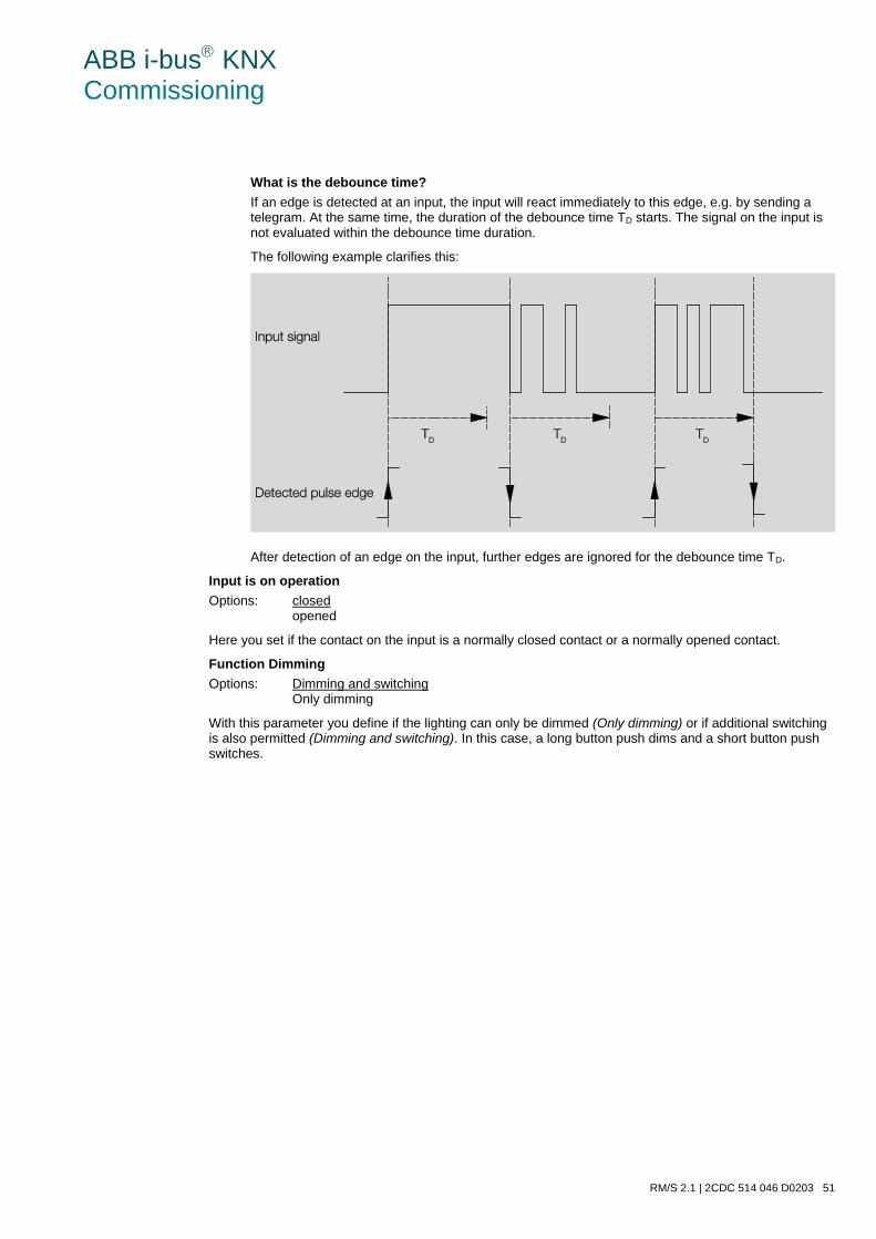
ABB i-bus KNX Commissioning
RM/S 2.1 | 2CDC 514 046 D0203 51
What is the debounce time? If an edge is detected at an input, the input will react immediately to this edge, e.g. by sending a telegram. At the same time, the duration of the debounce time TD starts. The signal on the input is not evaluated within the debounce time duration.
The following example clarifies this:
After detection of an edge on the input, further edges are ignored for the debounce time TD.
Input is on operation Options: closed
opened
Here you set if the contact on the input is a normally closed contact or a normally opened contact.
Function Dimming Options: Dimming and switching
Only dimming
With this parameter you define if the lighting can only be dimmed (Only dimming) or if additional switching is also permitted (Dimming and switching). In this case, a long button push dims and a short button push switches.
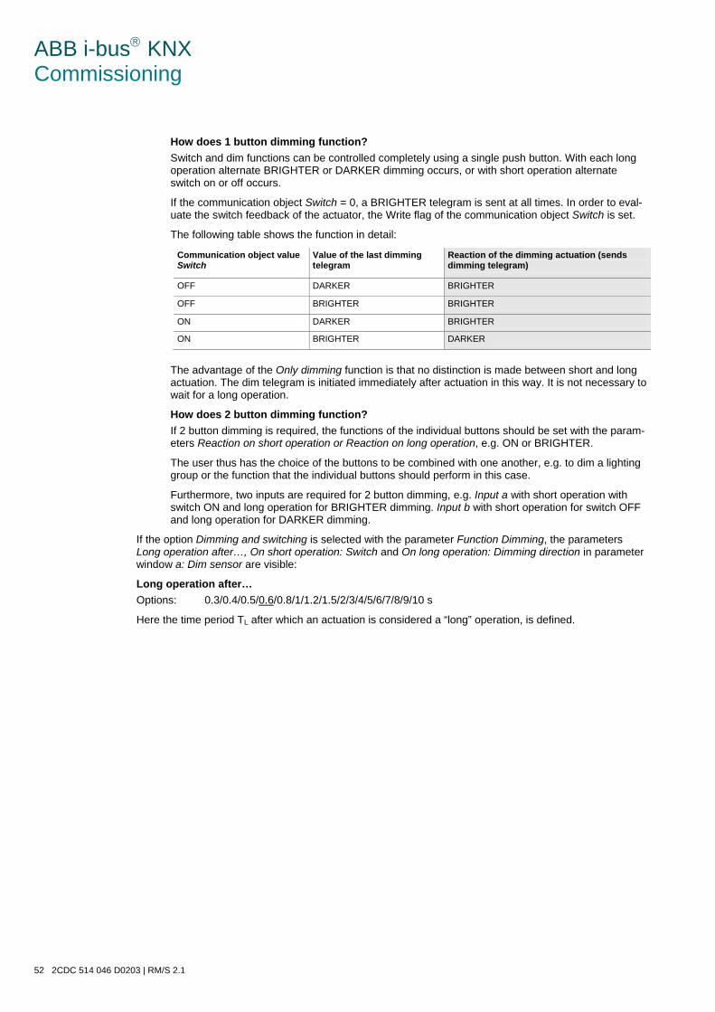
ABB i-bus KNX Commissioning
52 2CDC 514 046 D0203 | RM/S 2.1
How does 1 button dimming function? Switch and dim functions can be controlled completely using a single push button. With each long operation alternate BRIGHTER or DARKER dimming occurs, or with short operation alternate switch on or off occurs.
If the communication object Switch = 0, a BRIGHTER telegram is sent at all times. In order to eval-uate the switch feedback of the actuator, the Write flag of the communication object Switch is set.
The following table shows the function in detail:
Communication object value Switch
Value of the last dimming telegram
Reaction of the dimming actuation (sends dimming telegram)
OFF DARKER BRIGHTER
OFF BRIGHTER BRIGHTER
ON DARKER BRIGHTER
ON BRIGHTER DARKER
The advantage of the Only dimming function is that no distinction is made between short and long actuation. The dim telegram is initiated immediately after actuation in this way. It is not necessary to wait for a long operation.
How does 2 button dimming function? If 2 button dimming is required, the functions of the individual buttons should be set with the param-eters Reaction on short operation or Reaction on long operation, e.g. ON or BRIGHTER.
The user thus has the choice of the buttons to be combined with one another, e.g. to dim a lighting group or the function that the individual buttons should perform in this case.
Furthermore, two inputs are required for 2 button dimming, e.g. Input a with short operation with switch ON and long operation for BRIGHTER dimming. Input b with short operation for switch OFF and long operation for DARKER dimming.
If the option Dimming and switching is selected with the parameter Function Dimming, the parameters Long operation after…, On short operation: Switch and On long operation: Dimming direction in parameter window a: Dim sensor are visible:
Long operation after… Options: 0.3/0.4/0.5/0.6/0.8/1/1.2/1.5/2/3/4/5/6/7/8/9/10 s
Here the time period TL after which an actuation is considered a “long” operation, is defined.
ABB i-bus KNX Commissioning
RM/S 2.1 | 2CDC 514 046 D0203 53
On short operation: switch Options: ON
OFF TOGGLE no reaction
This parameter defines if the communication object Telegram switch TOGGLEs with short operation (typi-cal: 1 button dimming) or only switches OFF or ON (typically: 2 button dimming).
• TOGGLE: A short operation changes the value of the communication object Telegram switch.
• ON: With short operation the value 1 is sent.
• OFF: With short operation the value 0 is sent.
On long operation: dimming direction Options: BRIGHTER
DARKER alternating alternating, BRIGHTER after switching ON alternating, DARKER after switching ON
With this parameter, you set what the communication object Dimming should send on the bus with a long operation. A long operation changes the value of the communication object Dimming telegram. With 1 but-ton dimming, the parameter alternating should be set here. In this case, the dimming telegram, which is di-ametrically opposed to the last dimming telegram, is sent.
• BRIGHTER: The communication object sends a BRIGHTER telegram.
• DARKER: The communication object sends a DARKER telegram.
• alternating: The communication object alternately sends a BRIGHTER and a DARKER telegram.
• alternating, BRIGHTER after switching ON: The communication object at the first time sends a BRIGHTER telegram after an ON telegram; thereafter it alternately sends BRIGHTER and DARKER telegrams.
• alternating, DARKER after switching ON: The communication object at the first time sends a DARKER telegram after an ON telegram, thereafter it alternately sends BRIGHTER and DARKER telegrams.
Note
If the option Only dimming is selected in the Function Dimming, only the parameter On operation: dim-ming direction is visible.
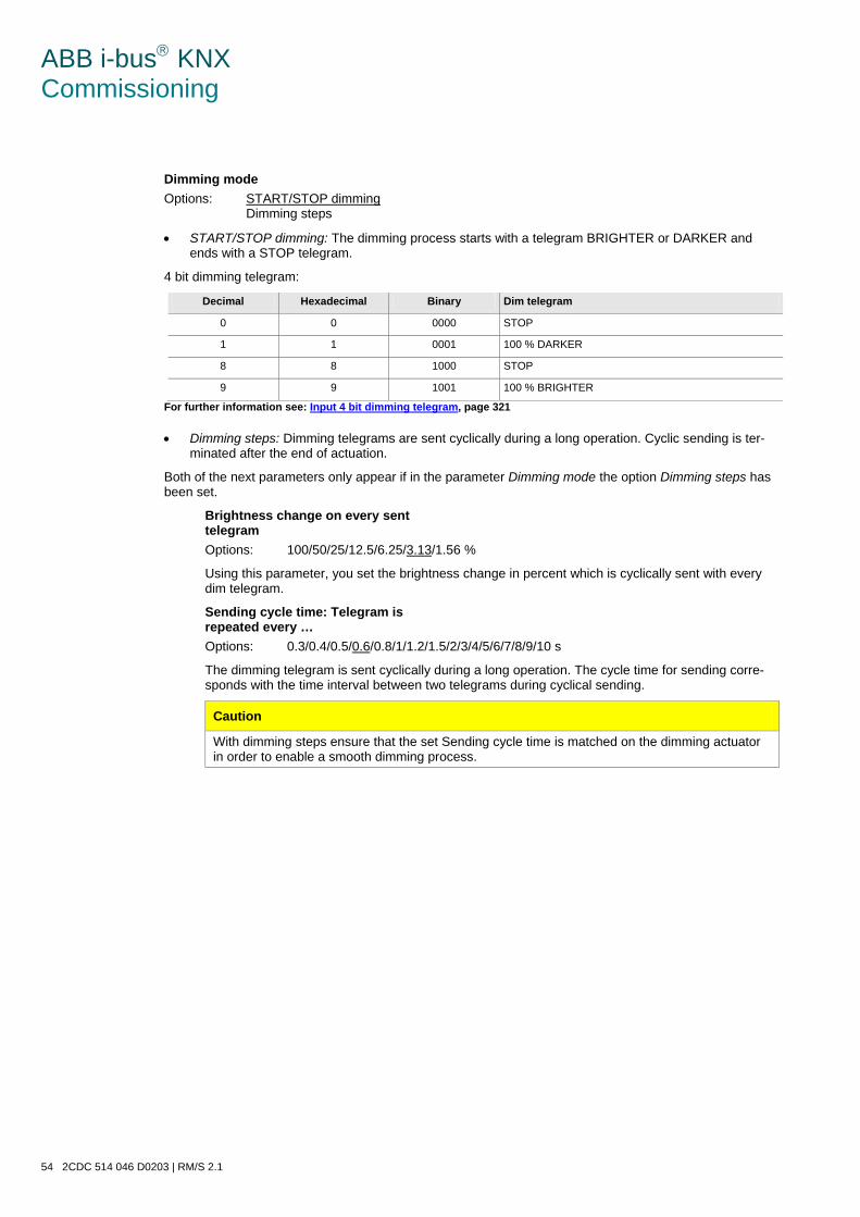
ABB i-bus KNX Commissioning
54 2CDC 514 046 D0203 | RM/S 2.1
Dimming mode Options: START/STOP dimming
Dimming steps
• START/STOP dimming: The dimming process starts with a telegram BRIGHTER or DARKER and ends with a STOP telegram.
4 bit dimming telegram:
Decimal Hexadecimal Binary Dim telegram
0 0 0000 STOP
1 1 0001 100 % DARKER
8 8 1000 STOP
9 9 1001 100 % BRIGHTER
For further information see: Input 4 bit dimming telegram, page 321
• Dimming steps: Dimming telegrams are sent cyclically during a long operation. Cyclic sending is ter-minated after the end of actuation.
Both of the next parameters only appear if in the parameter Dimming mode the option Dimming steps has been set.
Brightness change on every sent telegram Options: 100/50/25/12.5/6.25/3.13/1.56 %
Using this parameter, you set the brightness change in percent which is cyclically sent with every dim telegram.
Sending cycle time: Telegram is repeated every … Options: 0.3/0.4/0.5/0.6/0.8/1/1.2/1.5/2/3/4/5/6/7/8/9/10 s
The dimming telegram is sent cyclically during a long operation. The cycle time for sending corre-sponds with the time interval between two telegrams during cyclical sending.
Caution
With dimming steps ensure that the set Sending cycle time is matched on the dimming actuator in order to enable a smooth dimming process.
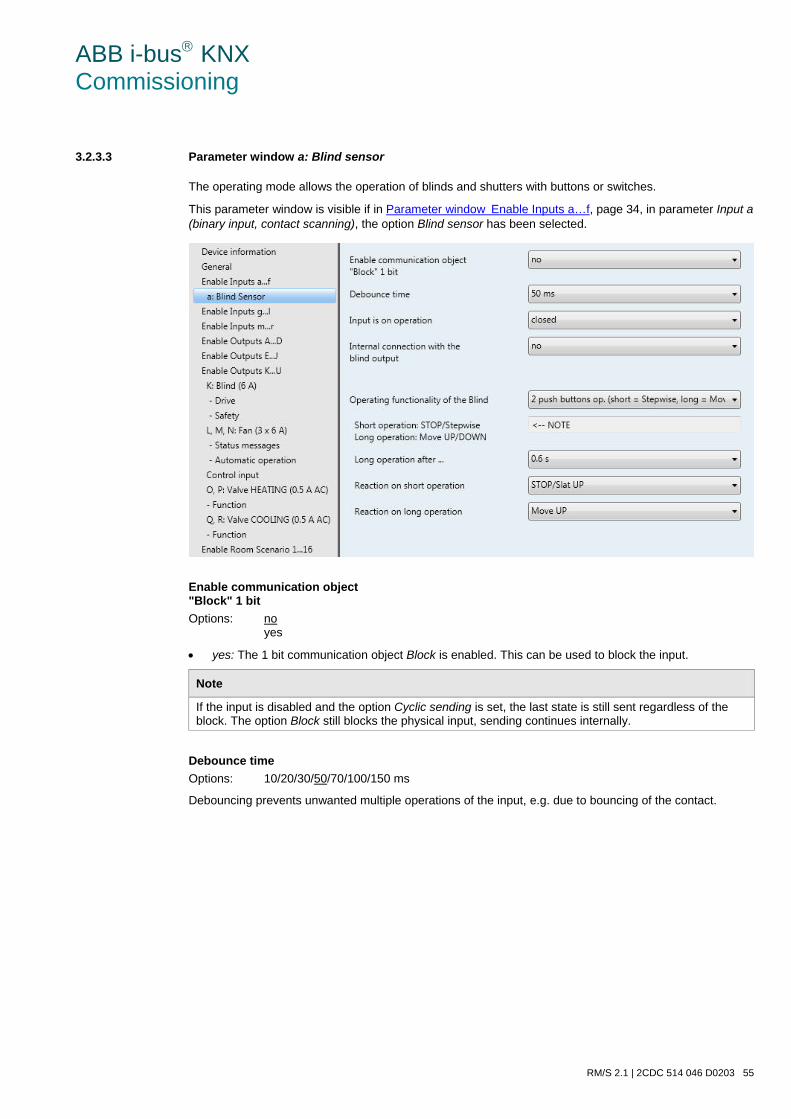
ABB i-bus KNX Commissioning
RM/S 2.1 | 2CDC 514 046 D0203 55
3.2.3.3 Parameter window a: Blind sensor
The operating mode allows the operation of blinds and shutters with buttons or switches.
This parameter window is visible if in Parameter windowEnable Inputs a…f, page 34, in parameter Input a (binary input, contact scanning), the option Blind sensor has been selected.
Enable communication object "Block" 1 bit Options: no
yes
• yes: The 1 bit communication object Block is enabled. This can be used to block the input.
Note
If the input is disabled and the option Cyclic sending is set, the last state is still sent regardless of the block. The option Block still blocks the physical input, sending continues internally.
Debounce time Options: 10/20/30/50/70/100/150 ms
Debouncing prevents unwanted multiple operations of the input, e.g. due to bouncing of the contact.
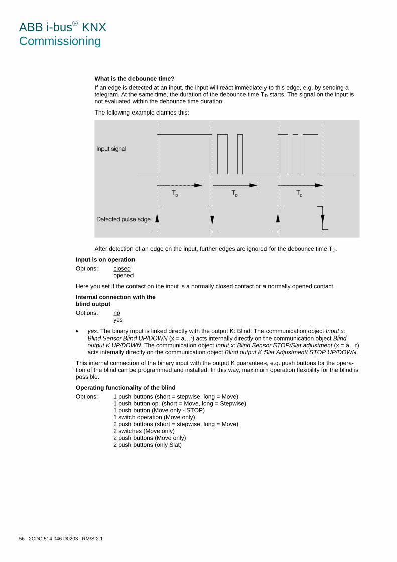
ABB i-bus KNX Commissioning
56 2CDC 514 046 D0203 | RM/S 2.1
What is the debounce time? If an edge is detected at an input, the input will react immediately to this edge, e.g. by sending a telegram. At the same time, the duration of the debounce time TD starts. The signal on the input is not evaluated within the debounce time duration.
The following example clarifies this:
After detection of an edge on the input, further edges are ignored for the debounce time TD.
Input is on operation Options: closed
opened
Here you set if the contact on the input is a normally closed contact or a normally opened contact.
Internal connection with the blind output Options: no
yes
• yes: The binary input is linked directly with the output K: Blind. The communication object Input x: Blind Sensor Blind UP/DOWN (x = a…r) acts internally directly on the communication object Blind output K UP/DOWN. The communication object Input x: Blind Sensor STOP/Slat adjustment (x = a…r) acts internally directly on the communication object Blind output K Slat Adjustment/ STOP UP/DOWN.
This internal connection of the binary input with the output K guarantees, e.g. push buttons for the opera-tion of the blind can be programmed and installed. In this way, maximum operation flexibility for the blind is possible.
Operating functionality of the blind Options: 1 push buttons (short = stepwise, long = Move)
1 push button op. (short = Move, long = Stepwise) 1 push button (Move only - STOP) 1 switch operation (Move only) 2 push buttons (short = stepwise, long = Move) 2 switches (Move only) 2 push buttons (Move only) 2 push buttons (only Slat)
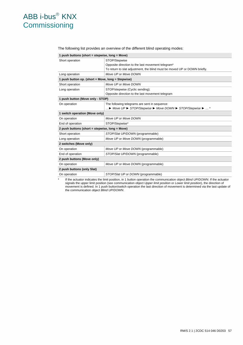
ABB i-bus KNX Commissioning
RM/S 2.1 | 2CDC 514 046 D0203 57
The following list provides an overview of the different blind operating modes:
1 push buttons (short = stepwise, long = Move) Short operation STOP/Stepwise
Opposite direction to the last movement telegram* To return to slat adjustment, the blind must be moved UP or DOWN briefly.
Long operation Move UP or Move DOWN 1 push button op. (short = Move, long = Stepwise) Short operation Move UP or Move DOWN Long operation STOP/stepwise (Cyclic sending);
Opposite direction to the last movement telegram 1 push button (Move only - STOP) On operation The following telegrams are sent in sequence:
…► Move UP ► STOP/Stepwise ► Move DOWN ► STOP/Stepwise ► … * 1 switch operation (Move only) On operation Move UP or Move DOWN End of operation STOP/Stepwise* 2 push buttons (short = stepwise, long = Move) Short operation STOP/Slat UP/DOWN (programmable) Long operation Move UP or Move DOWN (programmable) 2 switches (Move only) On operation Move UP or Move DOWN (programmable) End of operation STOP/Slat UP/DOWN (programmable) 2 push buttons (Move only) On operation Move UP or Move DOWN (programmable) 2 push buttons (only Slat) On operation STOP/Slat UP or DOWN (programmable)
* If the actuator indicates the limit position, in 1 button operation the communication object Blind UP/DOWN. If the actuator signals the upper limit position (see communication object Upper limit position or Lower limit position), the direction of movement is defined. In 1 push button/switch operation the last direction of movement is determined via the last update of the communication object Blind UP/DOWN.
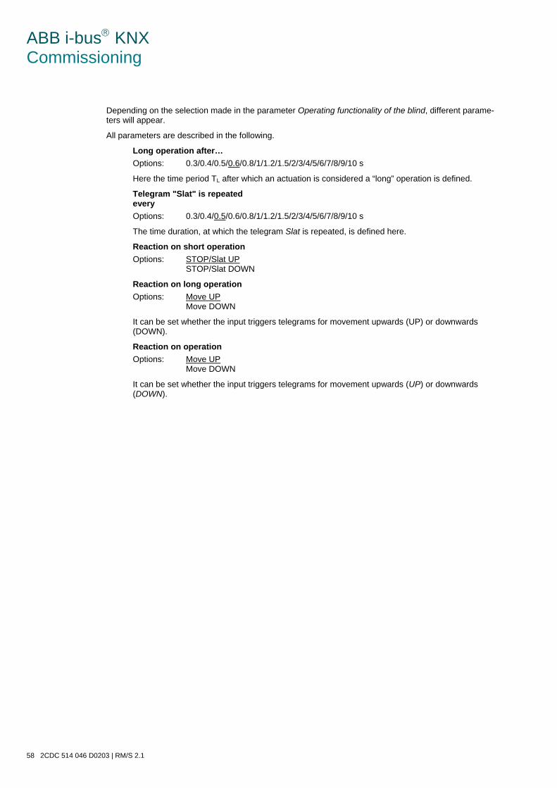
ABB i-bus KNX Commissioning
58 2CDC 514 046 D0203 | RM/S 2.1
Depending on the selection made in the parameter Operating functionality of the blind, different parame-ters will appear.
All parameters are described in the following.
Long operation after… Options: 0.3/0.4/0.5/0.6/0.8/1/1.2/1.5/2/3/4/5/6/7/8/9/10 s
Here the time period TL after which an actuation is considered a “long” operation is defined.
Telegram "Slat" is repeated every Options: 0.3/0.4/0.5/0.6/0.8/1/1.2/1.5/2/3/4/5/6/7/8/9/10 s
The time duration, at which the telegram Slat is repeated, is defined here.
Reaction on short operation Options: STOP/Slat UP
STOP/Slat DOWN
Reaction on long operation Options: Move UP
Move DOWN
It can be set whether the input triggers telegrams for movement upwards (UP) or downwards (DOWN).
Reaction on operation Options: Move UP
Move DOWN
It can be set whether the input triggers telegrams for movement upwards (UP) or downwards (DOWN).
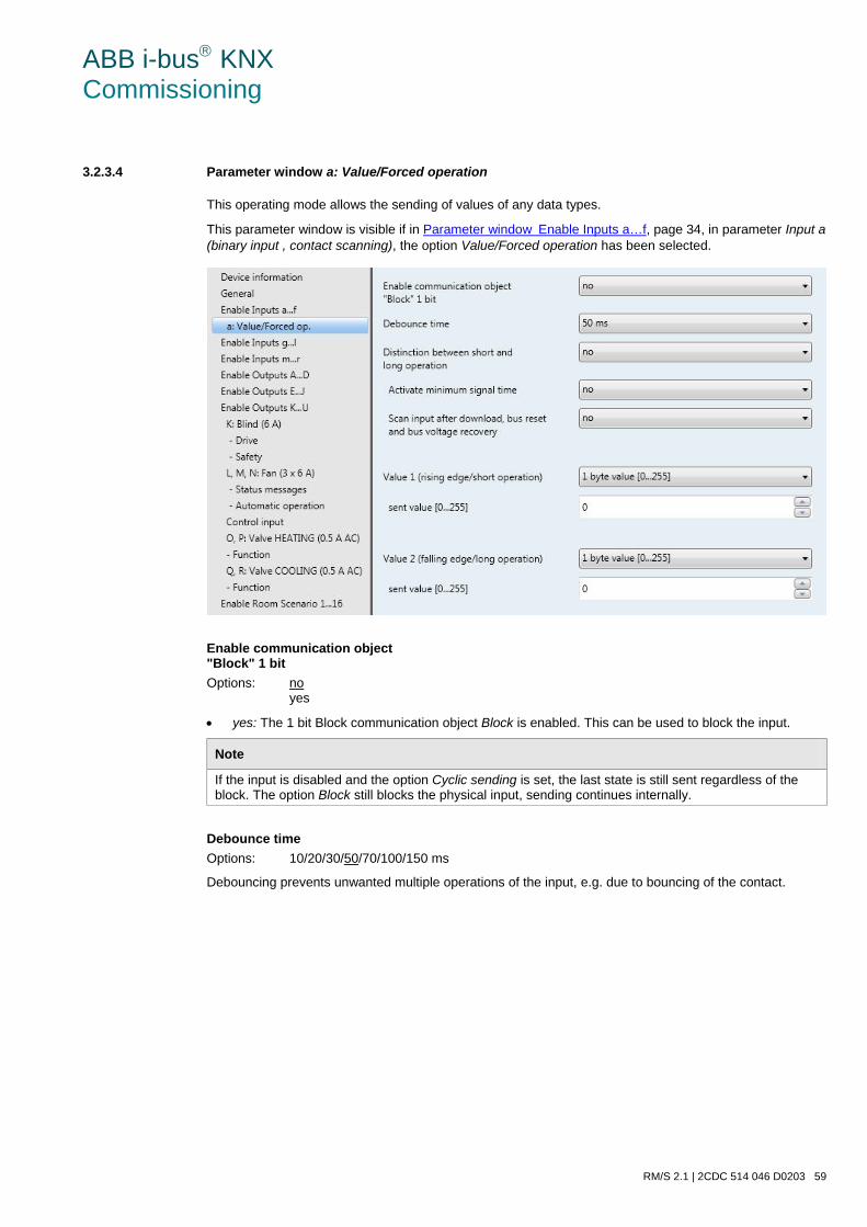
ABB i-bus KNX Commissioning
RM/S 2.1 | 2CDC 514 046 D0203 59
3.2.3.4 Parameter window a: Value/Forced operation
This operating mode allows the sending of values of any data types.
This parameter window is visible if in Parameter windowEnable Inputs a…f, page 34, in parameter Input a (binary input , contact scanning), the option Value/Forced operation has been selected.
Enable communication object "Block" 1 bit Options: no
yes
• yes: The 1 bit Block communication object Block is enabled. This can be used to block the input.
Note
If the input is disabled and the option Cyclic sending is set, the last state is still sent regardless of the block. The option Block still blocks the physical input, sending continues internally.
Debounce time Options: 10/20/30/50/70/100/150 ms
Debouncing prevents unwanted multiple operations of the input, e.g. due to bouncing of the contact.
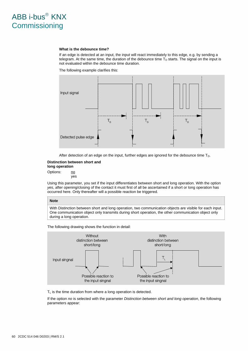
ABB i-bus KNX Commissioning
60 2CDC 514 046 D0203 | RM/S 2.1
What is the debounce time? If an edge is detected at an input, the input will react immediately to this edge, e.g. by sending a telegram. At the same time, the duration of the debounce time TD starts. The signal on the input is not evaluated within the debounce time duration.
The following example clarifies this:
After detection of an edge on the input, further edges are ignored for the debounce time TD.
Distinction between short and long operation Options: no
yes
Using this parameter, you set if the input differentiates between short and long operation. With the option yes, after opening/closing of the contact it must first of all be ascertained if a short or long operation has occurred here. Only thereafter will a possible reaction be triggered.
Note
With Distinction between short and long operation, two communication objects are visible for each input. One communication object only transmits during short operation, the other communication object only during a long operation.
The following drawing shows the function in detail:
TL is the time duration from where a long operation is detected.
If the option no is selected with the parameter Distinction between short and long operation, the following parameters appear:
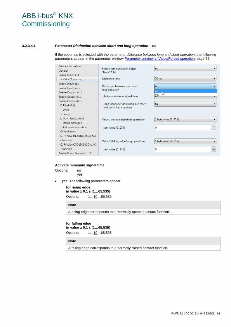
ABB i-bus KNX Commissioning
RM/S 2.1 | 2CDC 514 046 D0203 61
3.2.3.4.1 Parameter Distinction between short and long operation – no
If the option no is selected with the parameter difference between long and short operation, the following parameters appear in the parameter window Parameter window a: Value/Forced operation, page 59:
Activate minimum signal time Options: no
yes
• yes: The following parameters appear:
for rising edge in value x 0.1 s [1…65,535] Options: 1…10…65,535
Note
A rising edge corresponds to a “normally opened contact function”.
for falling edge in value x 0.1 s [1…65,535] Options: 1…10…65,535
Note
A falling edge corresponds to a normally closed contact function.
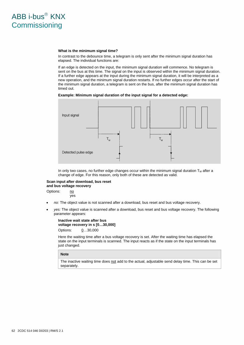
ABB i-bus KNX Commissioning
62 2CDC 514 046 D0203 | RM/S 2.1
What is the minimum signal time? In contrast to the debounce time, a telegram is only sent after the minimum signal duration has elapsed. The individual functions are:
If an edge is detected on the input, the minimum signal duration will commence. No telegram is sent on the bus at this time. The signal on the input is observed within the minimum signal duration. If a further edge appears at the input during the minimum signal duration, it will be interpreted as a new operation, and the minimum signal duration restarts. If no further edges occur after the start of the minimum signal duration, a telegram is sent on the bus, after the minimum signal duration has timed out.
Example: Minimum signal duration of the input signal for a detected edge:
In only two cases, no further edge changes occur within the minimum signal duration TM after a change of edge. For this reason, only both of these are detected as valid.
Scan input after download, bus reset and bus voltage recovery Options: no
yes
• no: The object value is not scanned after a download, bus reset and bus voltage recovery.
• yes: The object value is scanned after a download, bus reset and bus voltage recovery. The following parameter appears:
Inactive wait state after bus voltage recovery in s [0…30,000] Options: 0…30,000
Here the waiting time after a bus voltage recovery is set. After the waiting time has elapsed the state on the input terminals is scanned. The input reacts as if the state on the input terminals has just changed.
Note
The inactive waiting time does not add to the actual, adjustable send delay time. This can be set separately.
ABB i-bus KNX Commissioning
RM/S 2.1 | 2CDC 514 046 D0203 63
Value 1 (rising edge/short operation) Options: no sending
1 bit value [0/1] 2 Bit value [Forced operation] 1 byte value [-128…127] 1 byte value [0…255] 1 byte value [8 bit scene] 2 byte value [-32,768…32,767] 2 byte value [0…65,565] 2-byte value [floating point] 3 byte value [time of day, weekday] 4 byte value [-2,147,483,648…2,147,483,647] 4 byte value [0…4,294,967,295]
This parameter serves for defining the data type which is sent when the contact is actuated.
Depending on the selection made in parameter Value 1 (rising edge / short operation), different parame-ters appear. All parameters are described in the following:
sent value [X] Options: ON/OFF/TOGGLE
0/1 -128…0…127 0…255 -32. 768…0…32. 767 0…65,535 -100…20…100 -2,147,483,648…0…2,147,483,647 0…4,294,967,295
This parameter defines the value which is sent on actuation. The value range is dependent on the set data type of the value X.
sent value Options: ON, activate Forced operation
OFF, activate Forced operation Disable Forced operation
This parameter defines the value which is sent on actuation.
ABB i-bus KNX Commissioning
64 2CDC 514 046 D0203 | RM/S 2.1
In the following table, the Forced operation function is explained:
Bit 1 Bit 0 Access Description
0 0 Free The switch communication object of the actuator is enabled by the binary input. The as-signed sensor can control the actuator via the switch object. The binary input does not control the actuator. Bit 0 of the value of the forced operation communication object is not evaluated. The forced operation communication object sends a telegram with the group addresses of the forced operation communication object and the status of the switch communication object with every state change of the switch communication object.
0 1 Free
1 0 Off The switch communication object of the actuator is disabled by the binary input. The as-signed sensor cannot control the actuator via the switch communication object. The binary input controls the actuator via the forced operation communication object. The actuator is switched off. Bit 0 of the value of the forced operation communication object is evaluated.
1 1 On The switch communication object of the actuator is disabled by the binary input. The as-signed sensor cannot control the actuator via the switch communication object. The binary input controls the actuator via the forced operation communication object. The actuator is switched ON.
8 bit scene Options: 1…64
This parameter defines the scene number which is sent on actuation.
Store/Call scene Options: call
save
This parameter defines whether the scene is to be recalled or stored.
Hour [0…23] Options: 0…23
Minute [0…59] Options: 0…59
Seconds [0…59] Options: 0…59
With these parameters, the hours, minutes and seconds are set which are to be send when actuat-ed.
ABB i-bus KNX Commissioning
RM/S 2.1 | 2CDC 514 046 D0203 65
Weekday Options: 0 = no day
1 = Monday 2 = Tuesday 3 = Wednesday 4 = Thursday 5 = Friday 6 = Saturday 7 = Sunday
Using these parameters, the weekday that is sent on actuation are set.
Value 2 (falling edge/long operation)
Note
The parameter descriptions of the parameter Value 2 (with a rising edge and with short opera-tion) correspond with those of parameters Value 1 (with a rising edge and with short operation).
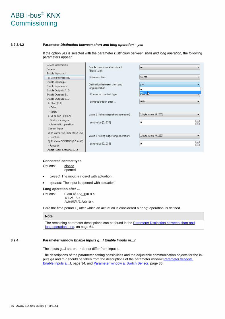
ABB i-bus KNX Commissioning
66 2CDC 514 046 D0203 | RM/S 2.1
3.2.3.4.2 Parameter Distinction between short and long operation – yes
If the option yes is selected with the parameter Distinction between short and long operation, the following parameters appear:
Connected contact type Options: closed
opened
• closed: The input is closed with actuation.
• opened: The input is opened with actuation.
Long operation after … Options: 0.3/0.4/0.5/0.6/0.8 s
1/1.2/1.5 s 2/3/4/5/6/7/8/9/10 s
Here the time period TL after which an actuation is considered a “long” operation, is defined.
Note
The remaining parameter descriptions can be found in the Parameter Distinction between short and long operation – no, on page 61.
3.2.4 Parameter window Enable Inputs g…l Enable Inputs m…r
The inputs g…l and m…r do not differ from input a.
The descriptions of the parameter setting possibilities and the adjustable communication objects for the in-puts g-l and m-r should be taken from the descriptions of the parameter window Parameter windowEnable Inputs a…f, page 34, and Parameter window a: Switch Sensor, page 36.
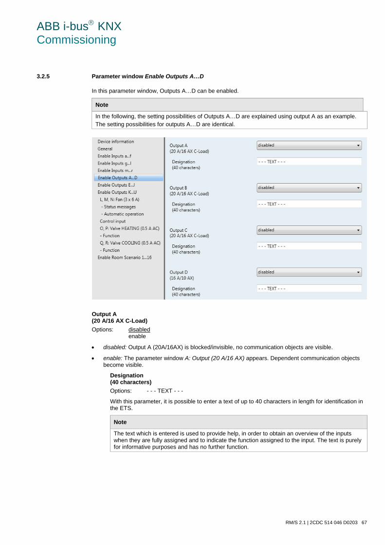
ABB i-bus KNX Commissioning
RM/S 2.1 | 2CDC 514 046 D0203 67
3.2.5 Parameter window Enable Outputs A…D
In this parameter window, Outputs A…D can be enabled.
Note
In the following, the setting possibilities of Outputs A…D are explained using output A as an example. The setting possibilities for outputs A…D are identical.
Output A (20 A/16 AX C-Load) Options: disabled
enable
• disabled: Output A (20A/16AX) is blocked/invisible, no communication objects are visible.
• enable: The parameter window A: Output (20 A/16 AX) appears. Dependent communication objects become visible.
Designation (40 characters) Options: - - - TEXT - - -
With this parameter, it is possible to enter a text of up to 40 characters in length for identification in the ETS.
Note
The text which is entered is used to provide help, in order to obtain an overview of the inputs when they are fully assigned and to indicate the function assigned to the input. The text is purely for informative purposes and has no further function.
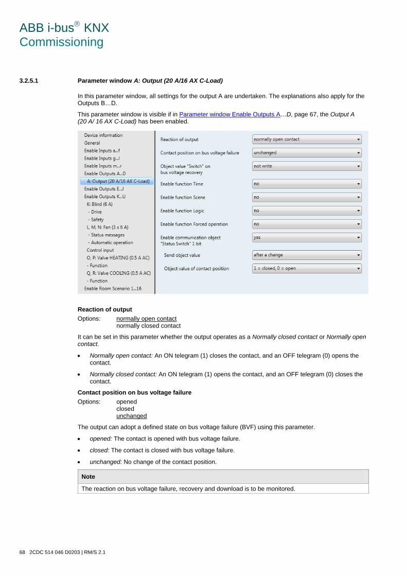
ABB i-bus KNX Commissioning
68 2CDC 514 046 D0203 | RM/S 2.1
3.2.5.1 Parameter window A: Output (20 A/16 AX C-Load)
In this parameter window, all settings for the output A are undertaken. The explanations also apply for the Outputs B…D.
This parameter window is visible if in Parameter window Enable Outputs A…D, page 67, the Output A (20 A/ 16 AX C-Load) has been enabled.
Reaction of output Options: normally open contact
normally closed contact
It can be set in this parameter whether the output operates as a Normally closed contact or Normally open contact.
• Normally open contact: An ON telegram (1) closes the contact, and an OFF telegram (0) opens the contact.
• Normally closed contact: An ON telegram (1) opens the contact, and an OFF telegram (0) closes the contact.
Contact position on bus voltage failure Options: opened
closed unchanged
The output can adopt a defined state on bus voltage failure (BVF) using this parameter.
• opened: The contact is opened with bus voltage failure.
• closed: The contact is closed with bus voltage failure.
• unchanged: No change of the contact position.
Note
The reaction on bus voltage failure, recovery and download is to be monitored.
ABB i-bus KNX Commissioning
RM/S 2.1 | 2CDC 514 046 D0203 69
Object value "Switch" on bus voltage recovery Options: not write
write with 0 write with 1
With this parameter, the output can be influenced by the value of the communication object Switch on bus voltage recovery.
The communication object Switch can be written with either a 0 or 1 when the bus voltage recovers. The contact position is redefined and set in dependence on the set device parameterization.
• not write: The communication object assumes the value 0. This value remains as it is until modified via the bus. The contact position is only re-evaluated at this time.
Note
The reaction on bus voltage failure, recovery and download is to be monitored. The Room Master draws the energy for switching the contact from the bus. After bus voltage is applied, sufficient energy is only available after about ten seconds in order to switch all contacts simultaneously. Depending on the set transmission and switching delay after recovery of bus voltage set in the parame-ter window General, the individual outputs will only assume the desired contact position after this time. If a shorter time is set, the RM/S will only switch the first contact when sufficient energy is stored in the Room Master, in order to ensure that enough energy is available to immediately bring all outputs safely to the required position with a renewed bus voltage failure.
Enable function Time Options: no
yes
• no: The parameter window remains disabled and invisible.
• yes: The parameter window - Time appears.
After the function Time has been enabled, the parameter window - Time is enabled. Further settings can be made here, e.g. on and off delays with staircase lighting.
Note
A more exact description of the function can be found at Communication objects output A, page 198, No. 136.
ABB i-bus KNX Commissioning
70 2CDC 514 046 D0203 | RM/S 2.1
Enable function Scene Options: no
yes
• no: The parameter window remains disabled and invisible.
• yes: The parameter window - Scene appears.
After the function Scene has been enabled, the parameter window - Scene is enabled. Here you can un-dertake further settings, e.g. allocation of the output to a scene or standard value.
Enable function Logic Options: no
yes
• no: The parameter window remains disabled and invisible.
• yes: The parameter window - Logic appears.
After the function Connection/Logic has been enabled, the parameter window - Logic is enabled. Here fur-ther settings can be undertaken, e.g. connection and linking of the connection.
Enable function Forced operation Options: no
yes
This parameter enables the function Forced operation.
A communication object forced operation is available for every output.
The forced operation (a 1 bit or 2 bit communication object per output) sets the output in a defined state, where – as long as the forced operation is active – it can only be changed via the communication object forced operation.
The switch state after the end of forced operation can be set using the parameter Contact position with end of the forced operation.
• yes: The following parameters appear:
Type of object "Forced operation" Options: 1 bit
2 bit
Using the 2 bit communication object, the output state is defined directly via the communication ob-ject value. The control of the output via the communication object Switch is blocked as long as the output is forcibly switched ON or OFF.
The following parameters appear when 1 bit is selected:
ABB i-bus KNX Commissioning
RM/S 2.1 | 2CDC 514 046 D0203 71
Contact position on Forced operation Options: ON
OFF unchanged
• ON: Contact position of the output during Forced operation.
• OFF: Contact position of the output during Forced operation.
• unchanged: Contact position of the output during Forced operation.
The options unchanged, ON and OFF related to the 1 bit forced operation object and determine the switching state of the output during forced operation. The forced operation relates to the 1 bit forced operation communication object of output X that is available to every output.
Contact position with end of the Forced operation Options: ON
OFF unchanged calculate present contact position
This parameter determines the contact position of the relay after the end of Forced operation.
• ON: The output is switched ON after Forced operation has ended
• OFF: The output is switched OFF after Forced operation has ended
• unchanged: The contact position is retained during Forced operation or Safety priority. The contact position only changes when a new calculated switch value is received.
calculate present contact position: After forced operation has ended, the value (switch value) is re-calculated, the switch position is recalculated and immediately initiated, i.e. the output continues to operate normally in the background during forced operation.
ABB i-bus KNX Commissioning
72 2CDC 514 046 D0203 | RM/S 2.1
The following parameters appear when 2 bit is selected:
Contact position with end of the Forced operation Options: ON
OFF unchanged calculate present contact position
This parameter determines the contact position of the relay after the end of forced operation.
• ON: The output is switched ON after forced operation has ended
• OFF: The output is switched OFF after forced operation has ended
• unchanged: The contact position is retained during forced operation or safety priority. The con-tact position only changes when a new calculated switch value is received.
calculate present contact position: After forced operation has ended, the value (switch value) is re-calculated, the switch position is recalculated and immediately initiated, i.e. the output continues to operate normally in the background during forced operation.
The telegram value which is sent via the 2 bit communication object determines the switch position as follows:
Value Bit 1 Bit 0 State Description 0 0 0 Free If the communication object Forced operation receives a telegram with the
value 0 (binary 00) or 1 (binary 01), the output is enabled and can be actu-ated via different communication objects. 1 0 1 Free
2 1 0 Forced OFF If the communication object Forced operation receives a telegram with the value 2 (binary 10), the output of the Room Master is forced OFF and re-mains disabled until forced operation is again deactivated. Actuation via another communication object is not possible as long as the forced operation is activated. The state of the output at the end of forced operation can be programmed.
3 1 1 Forced ON If the communication object Forced operation receives a telegram with the value 3 (binary 11), the output of the Room Master is forced ON and re-mains disabled until forced operation is again deactivated. Actuation via another communication object is not possible as long as the forced operation is activated.
ABB i-bus KNX Commissioning
RM/S 2.1 | 2CDC 514 046 D0203 73
Enable communication object "Status Switch" 1 bit Options: no
yes
Caution If an internal connection with an output is selected, and at the same time the reaction to an event is pa-rameterized with TOGGLE, the communication object Switch 1 of the binary input is updated with the inverted value of the communication object Status Switch of the output. Ensure that the communication object Status Switch of the output is enabled. The settings normally closed contact/normally open contact and Invert status should be parameterized, so that a TOGGLE function is possible.
• yes: The following parameters appear:
Send object value Options: no, update only
after a change after request after a change or request
• no, update only: The status is updated but not sent.
• after a change: The status is sent after a change.
• after request: The status is sent after a request.
• after a change or request: The status is sent after a change or a request.
Object value of contact position Options: 1 = closed, 0 = open
0 = closed, 1 = open
With this parameter, the communication object value of the switch status (Status switch) is defined.
• 1 = closed, 0 = open: A closed contact is represented by communication object value 1 and an open contact is represented by the value 0.
• 0 = closed, 1 = open: A closed contact is represented by communication object value 0 and an open contact is represented by the value 1.
Note
The contact position and thus the switch status can result from a series of priorities and links.
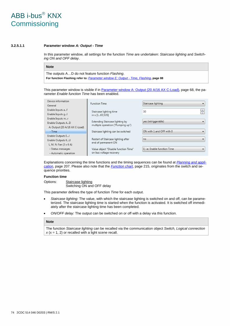
ABB i-bus KNX Commissioning
74 2CDC 514 046 D0203 | RM/S 2.1
3.2.5.1.1 Parameter window A: Output - Time
In this parameter window, all settings for the function Time are undertaken: Staircase lighting and Switch-ing ON and OFF delay.
Note
The outputs A…D do not feature function Flashing. For function Flashing refer to: Parameter window E: Output - Time, Flashing, page 88
This parameter window is visible if in Parameter window A: Output (20 A/16 AX C-Load), page 68, the pa-rameter Enable function Time has been enabled.
Explanations concerning the time functions and the timing sequences can be found at Planning and appli-cation, page 207. Please also note that the Function chart, page 215, originates from the switch and se-quence priorities.
Function time Options: Staircase lighting
Switching ON and OFF delay
This parameter defines the type of function Time for each output.
• Staircase lighting: The value, with which the staircase lighting is switched on and off, can be parame-terized. The staircase lighting time is started when the function is activated. It is switched off immedi-ately after the staircase lighting time has been completed.
• ON/OFF delay: The output can be switched on or off with a delay via this function.
Note
The function Staircase lighting can be recalled via the communication object Switch, Logical connection x (x = 1, 2) or recalled with a light scene recall.
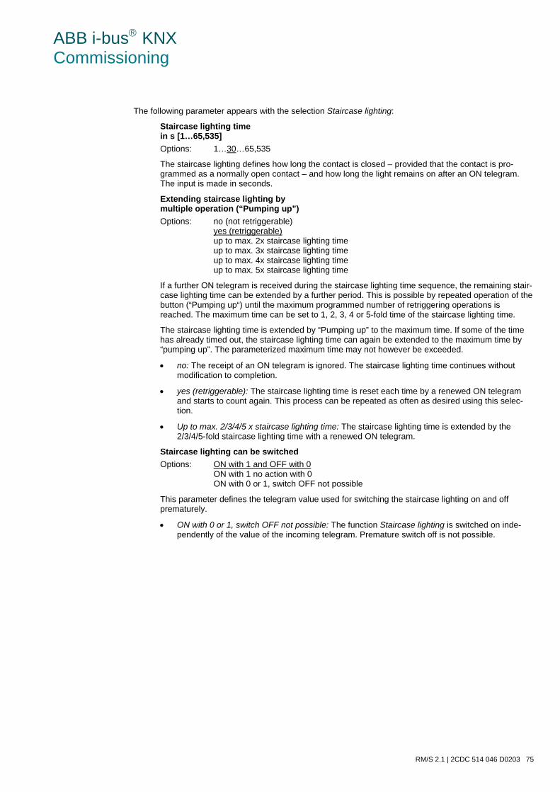
ABB i-bus KNX Commissioning
RM/S 2.1 | 2CDC 514 046 D0203 75
The following parameter appears with the selection Staircase lighting:
Staircase lighting time in s [1…65,535] Options: 1…30…65,535
The staircase lighting defines how long the contact is closed – provided that the contact is pro-grammed as a normally open contact – and how long the light remains on after an ON telegram. The input is made in seconds.
Extending staircase lighting by multiple operation (“Pumping up”) Options: no (not retriggerable)
yes (retriggerable) up to max. 2x staircase lighting time up to max. 3x staircase lighting time up to max. 4x staircase lighting time up to max. 5x staircase lighting time
If a further ON telegram is received during the staircase lighting time sequence, the remaining stair-case lighting time can be extended by a further period. This is possible by repeated operation of the button (“Pumping up“) until the maximum programmed number of retriggering operations is reached. The maximum time can be set to 1, 2, 3, 4 or 5-fold time of the staircase lighting time.
The staircase lighting time is extended by “Pumping up” to the maximum time. If some of the time has already timed out, the staircase lighting time can again be extended to the maximum time by “pumping up”. The parameterized maximum time may not however be exceeded.
• no: The receipt of an ON telegram is ignored. The staircase lighting time continues without modification to completion.
• yes (retriggerable): The staircase lighting time is reset each time by a renewed ON telegram and starts to count again. This process can be repeated as often as desired using this selec-tion.
• Up to max. 2/3/4/5 x staircase lighting time: The staircase lighting time is extended by the 2/3/4/5-fold staircase lighting time with a renewed ON telegram.
Staircase lighting can be switched Options: ON with 1 and OFF with 0
ON with 1 no action with 0 ON with 0 or 1, switch OFF not possible
This parameter defines the telegram value used for switching the staircase lighting on and off prematurely.
• ON with 0 or 1, switch OFF not possible: The function Staircase lighting is switched on inde-pendently of the value of the incoming telegram. Premature switch off is not possible.
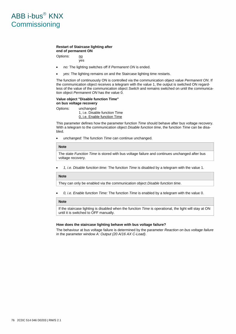
ABB i-bus KNX Commissioning
76 2CDC 514 046 D0203 | RM/S 2.1
Restart of Staircase lighting after end of permanent ON Options: no
yes
• no: The lighting switches off if Permanent ON is ended.
• yes: The lighting remains on and the Staircase lighting time restarts.
The function of continuously ON is controlled via the communication object value Permanent ON. If the communication object receives a telegram with the value 1, the output is switched ON regard-less of the value of the communication object Switch and remains switched on until the communica-tion object Permanent ON has the value 0.
Value object "Disable function Time" on bus voltage recovery Options: unchanged
1, i.e. Disable function Time 0, i.e. Enable function Time
This parameter defines how the parameter function Time should behave after bus voltage recovery. With a telegram to the communication object Disable function time, the function Time can be disa-bled.
• unchanged: The function Time can continue unchanged.
Note
The state Function Time is stored with bus voltage failure and continues unchanged after bus voltage recovery.
• 1, i.e. Disable function time: The function Time is disabled by a telegram with the value 1.
Note
They can only be enabled via the communication object Disable function time.
• 0, i.e. Enable function Time: The function Time is enabled by a telegram with the value 0.
Note
If the staircase lighting is disabled when the function Time is operational, the light will stay at ON until it is switched to OFF manually.
How does the staircase lighting behave with bus voltage failure? The behaviour at bus voltage failure is determined by the parameter Reaction on bus voltage failure in the parameter window A: Output (20 A/16 AX C-Load).

ABB i-bus KNX Commissioning
RM/S 2.1 | 2CDC 514 046 D0203 77
How does the staircase lighting behave with bus voltage recovery? The behaviour at bus voltage recovery is defined by two conditions.
1. By the communication object Disable function time. If the staircase lighting is blocked after bus voltage recovery, the staircase lighting can only be switched on or off via the communication object Switch.
2. By the parameterization of the communication object Switch. Whether the light is switched on or off with bus voltage recovery depends on the programming of the communication object Switch.
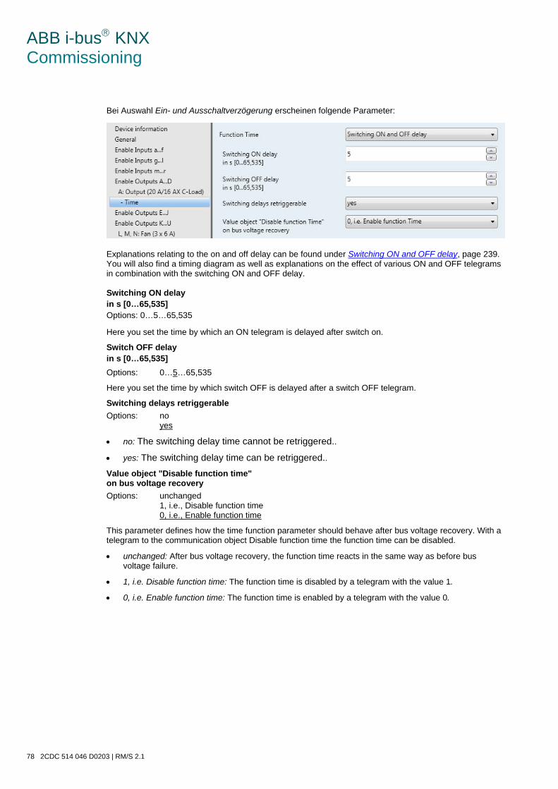
ABB i-bus KNX Commissioning
78 2CDC 514 046 D0203 | RM/S 2.1
Bei Auswahl Ein- und Ausschaltverzögerung erscheinen folgende Parameter:
Explanations relating to the on and off delay can be found under Switching ON and OFF delay, page 239. You will also find a timing diagram as well as explanations on the effect of various ON and OFF telegrams in combination with the switching ON and OFF delay. Switching ON delay in s [0…65,535] Options: 0…5…65,535
Here you set the time by which an ON telegram is delayed after switch on.
Switch OFF delay in s [0…65,535] Options: 0…5…65,535
Here you set the time by which switch OFF is delayed after a switch OFF telegram.
Switching delays retriggerable Options: no
yes
• no: The switching delay time cannot be retriggered..
• yes: The switching delay time can be retriggered.. Value object "Disable function time" on bus voltage recovery Options: unchanged
1, i.e., Disable function time 0, i.e., Enable function time
This parameter defines how the time function parameter should behave after bus voltage recovery. With a telegram to the communication object Disable function time the function time can be disabled.
• unchanged: After bus voltage recovery, the function time reacts in the same way as before bus voltage failure.
• 1, i.e. Disable function time: The function time is disabled by a telegram with the value 1.
• 0, i.e. Enable function time: The function time is enabled by a telegram with the value 0.
ABB i-bus KNX Commissioning
RM/S 2.1 | 2CDC 514 046 D0203 79
How does the staircase lighting behave with bus voltage failure? The behaviour at bus voltage failure is determined by the parameter Reaction on bus voltage failure in the parameter window A: Output (20 A/16 AX C-Load).
How does the staircase lighting behave with bus voltage recovery? The behaviour at bus voltage recovery is defined by two conditions.
1. By the communication object Disable function time. If the staircase lighting is blocked after bus voltage recovery, the staircase lighting can only be switched on or off via the communication object Switch.
2. By the parameterization of the communication object Switch. Whether the light is switched on or off with bus voltage recovery depends on the programming of the communication object Switch.
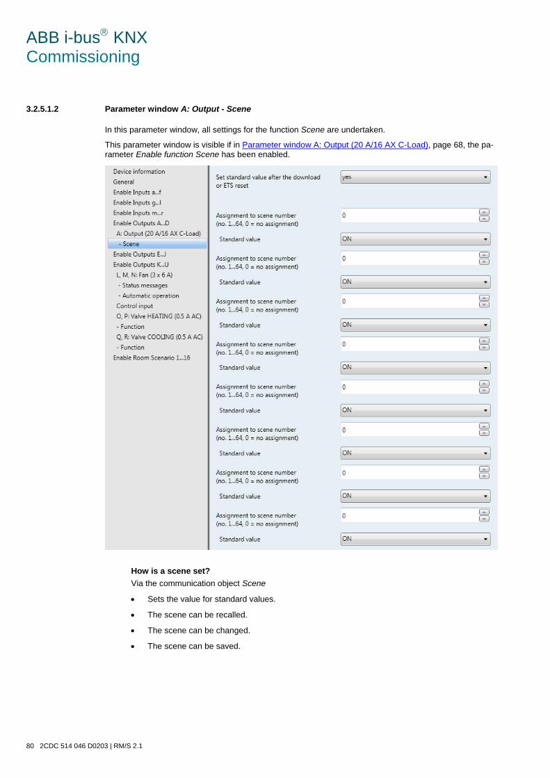
ABB i-bus KNX Commissioning
80 2CDC 514 046 D0203 | RM/S 2.1
3.2.5.1.2 Parameter window A: Output - Scene
In this parameter window, all settings for the function Scene are undertaken.
This parameter window is visible if in Parameter window A: Output (20 A/16 AX C-Load), page 68, the pa-rameter Enable function Scene has been enabled.
How is a scene set? Via the communication object Scene
• Sets the value for standard values.
• The scene can be recalled.
• The scene can be changed.
• The scene can be saved.
ABB i-bus KNX Commissioning
RM/S 2.1 | 2CDC 514 046 D0203 81
An example: Scene recall:
• Send value 0…63 for the scene (no. 1…64) to the communication object Scene.
Scene change and save:
• Scene no. 24 is assigned to the output with the value ON.
• Scene no. 24 should be assigned to the output with the value OFF:
o Set the output to OFF with a switch telegram.
o Send value 151 (128 + 23) for storage of scene number 24 to the communication object Scene.
General values for scene storage:
• 128 + (0…63) for the scene (No. 1…64)
o The stored scene values are retained until there is a device reset.
Note
After a device reset, the parameterized values can be reactivated. For further information see: Reset via bus, page 258
Set standard value after the download or ETS reset Options: no
yes
• no: The standard values are not set after a download or ETS reset.
• yes: The standard values are set after a download or ETS reset.
Assignment to scene number [no. 1…64, 0 = no assignment] Options: 0…64
Using the function Scene, up to 64 scenes are managed using just a single group address. With this group address, all slaves integrated into a scene are linked via a 1 byte communication object. The following in-formation is contained in a telegram:
• Number of the scene (1…64) as well as
• Telegram: Call scene or store scene.
The output can be integrated in up to eight scenes. So for example, the scene can be switched on in the morning and switched off in the evening, or the output can be integrated into light scenes.
If a telegram is received on the communication object Scene, the sent scene number is allocated for all outputs which carry out the stored scene position, or the current position is stored as the new scene posi-tion.
ABB i-bus KNX Commissioning
82 2CDC 514 046 D0203 | RM/S 2.1
Standard value Options: ON
OFF
Here you set the state that the output has when the scene is recalled.
Note
When a scene is recalled: • the function Time is restarted. • the logical connections are re-evaluated.
For further information see: Communication objects Output A, page 198, Function Scene, page 221 and Code table scene (8 bit), page 320.
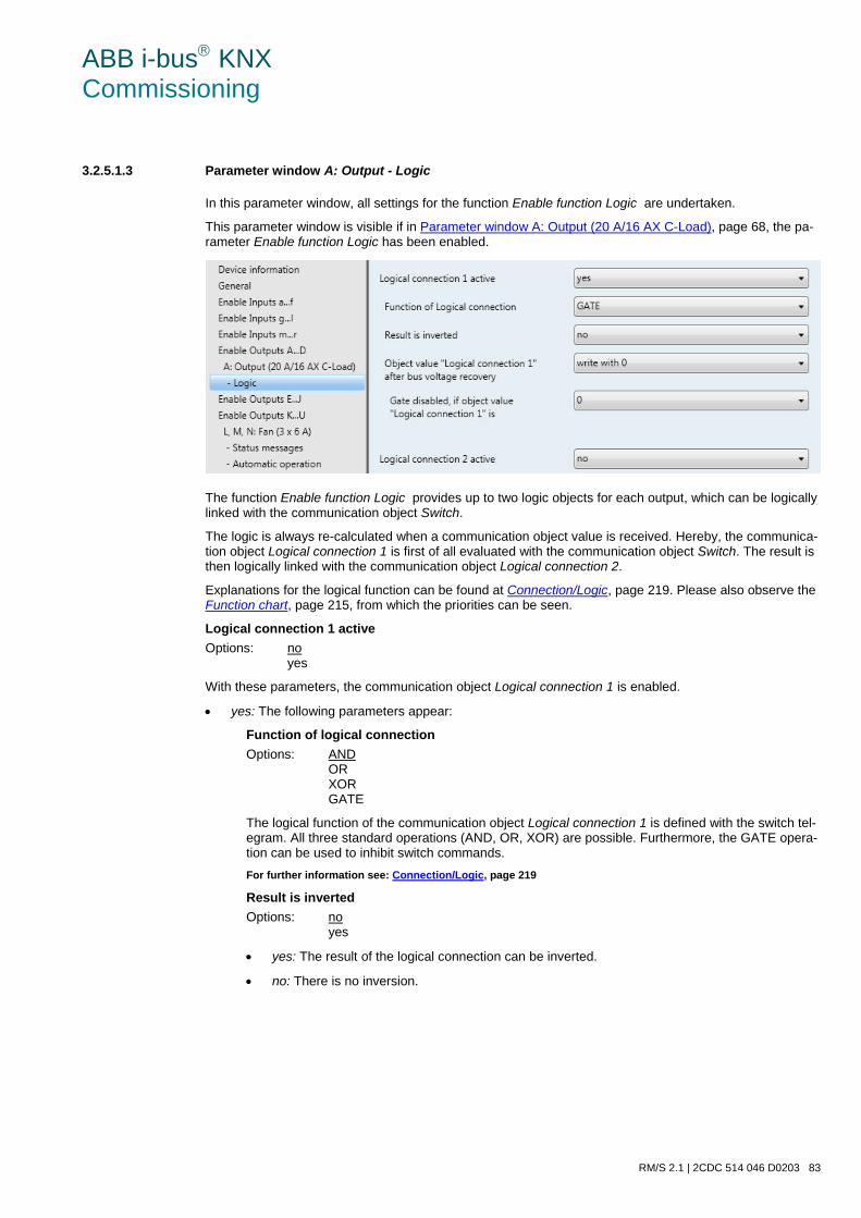
ABB i-bus KNX Commissioning
RM/S 2.1 | 2CDC 514 046 D0203 83
3.2.5.1.3 Parameter window A: Output - Logic
In this parameter window, all settings for the function Enable function Logic are undertaken.
This parameter window is visible if in Parameter window A: Output (20 A/16 AX C-Load), page 68, the pa-rameter Enable function Logic has been enabled.
The function Enable function Logic provides up to two logic objects for each output, which can be logically linked with the communication object Switch.
The logic is always re-calculated when a communication object value is received. Hereby, the communica-tion object Logical connection 1 is first of all evaluated with the communication object Switch. The result is then logically linked with the communication object Logical connection 2.
Explanations for the logical function can be found at Connection/Logic, page 219. Please also observe the Function chart, page 215, from which the priorities can be seen.
Logical connection 1 active Options: no
yes
With these parameters, the communication object Logical connection 1 is enabled.
• yes: The following parameters appear:
Function of logical connection Options: AND
OR XOR GATE
The logical function of the communication object Logical connection 1 is defined with the switch tel-egram. All three standard operations (AND, OR, XOR) are possible. Furthermore, the GATE opera-tion can be used to inhibit switch commands. For further information see: Connection/Logic, page 219
Result is inverted Options: no
yes
• yes: The result of the logical connection can be inverted.
• no: There is no inversion.

ABB i-bus KNX Commissioning
84 2CDC 514 046 D0203 | RM/S 2.1
Object value “Logical connection 1” after bus voltage recovery Options: not write
write with 0 write with 1
This parameter defines the value allocated to the communication object Logical connection 1 with bus voltage recovery.
• not write: after bus voltage recovery, the value 0 remains in the communication object Switch. This value remains as it is until the communication object is modified via the bus. The contact position is only re-evaluated and set at this time. The correct status of the contact position is displayed via the communication object Status switch independently of the value of the com-munication object Switch. A precondition however is that no manual switching actions have oc-curred on the outputs A, B, C or D.
Note
The values of the communication objects Logical connection 1/2 are stored at bus voltage fail-ure. The values are set again after a bus voltage recovery. If values are not assigned for communication objects Logical connection 1/2, they will be deac-tivated. With a reset via the bus, the values of the communication objects Logical connection 1/2 remain unchanged.
A further parameter appears if GATE is selected with the parameter Function of logical connection:
Gate disabled, if object value “Logical connection 1” is.
Options: 1 0
This parameter defines the value at which the communication object Logical connection 1 disables the GATE.
Disabling of the gate means that the telegrams received on the communication object Switch are ignored. As long as the GATE is activated, the value that was sent last to the input of the GATE remains on the output. After a gate is blocked, the value that was on the output before the block remains on the output of the gate.
After the gate is enabled, this value will be retained until a new value is received. For further information see: Function chart, page 215 The GATE is disabled after bus voltage failure and remains deactivated after bus voltage recovery.
Logical connection 2 active The same programming options exist as those for parameter Logical connection 1 active.
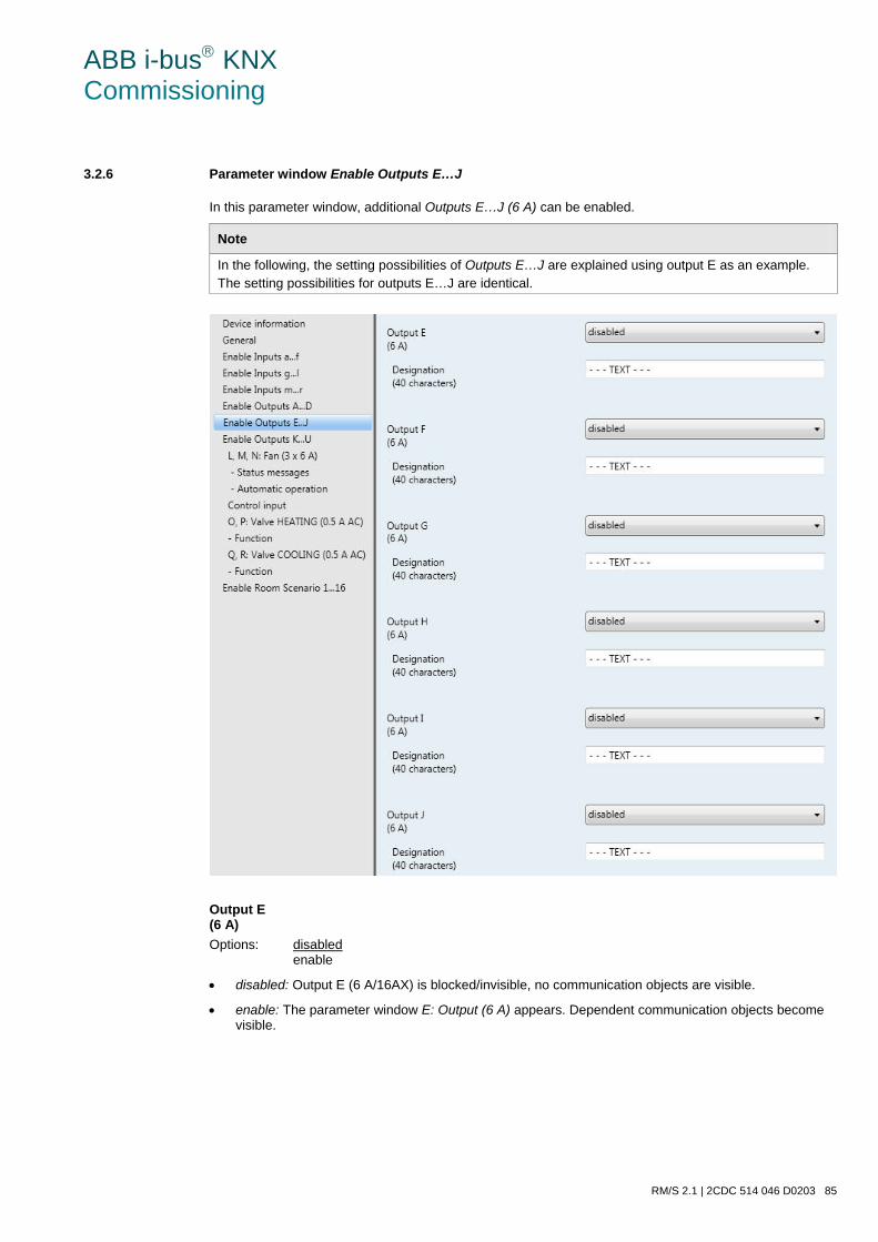
ABB i-bus KNX Commissioning
RM/S 2.1 | 2CDC 514 046 D0203 85
3.2.6 Parameter window Enable Outputs E…J
In this parameter window, additional Outputs E…J (6 A) can be enabled.
Note
In the following, the setting possibilities of Outputs E…J are explained using output E as an example. The setting possibilities for outputs E…J are identical.
Output E (6 A) Options: disabled
enable
• disabled: Output E (6 A/16AX) is blocked/invisible, no communication objects are visible.
• enable: The parameter window E: Output (6 A) appears. Dependent communication objects become visible.

ABB i-bus KNX Commissioning
86 2CDC 514 046 D0203 | RM/S 2.1
Designation (40 characters)
Options: - - - TEXT - - -
With this parameter, it is possible to enter a text of up to 40 characters in length for identification in the ETS.
Note
The text which is entered is used to provide help, in order to obtain an overview of the inputs when they are fully assigned and to indicate the function assigned to the input. The text is purely for informative purposes and has no further function.
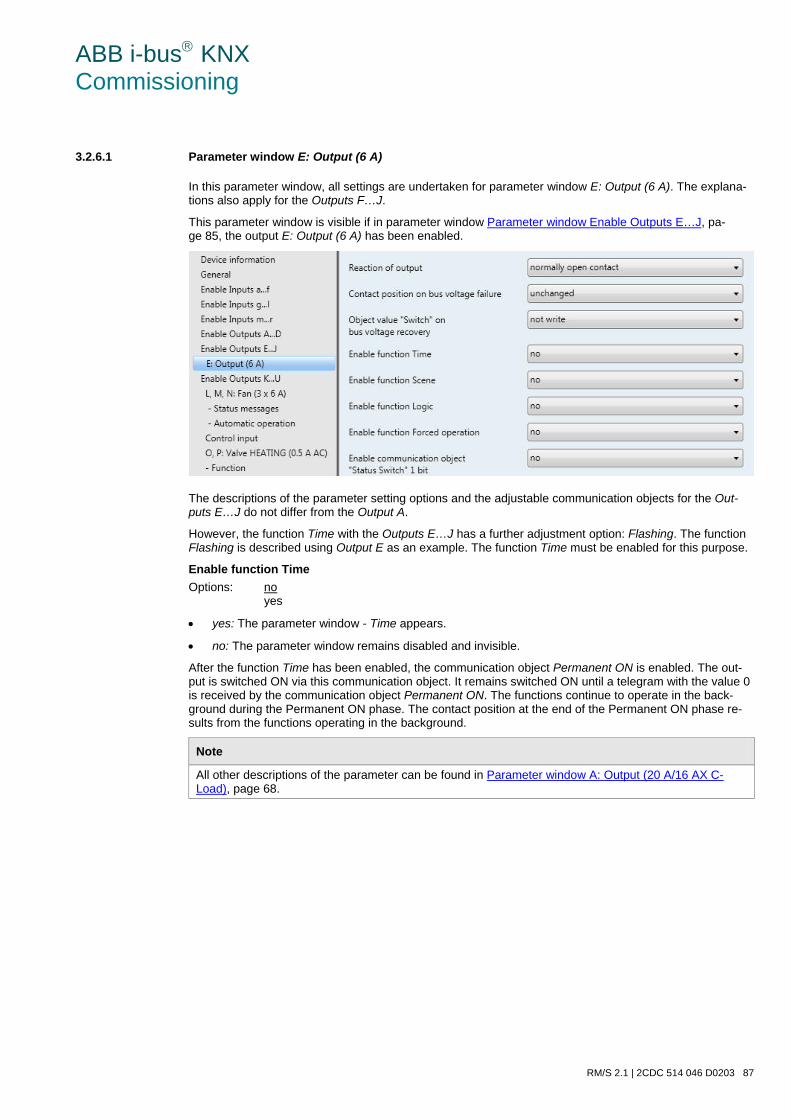
ABB i-bus KNX Commissioning
RM/S 2.1 | 2CDC 514 046 D0203 87
3.2.6.1 Parameter window E: Output (6 A)
In this parameter window, all settings are undertaken for parameter window E: Output (6 A). The explana-tions also apply for the Outputs F…J.
This parameter window is visible if in parameter window Parameter window Enable Outputs E…J, pa-ge 85, the output E: Output (6 A) has been enabled.
The descriptions of the parameter setting options and the adjustable communication objects for the Out-puts E…J do not differ from the Output A.
However, the function Time with the Outputs E…J has a further adjustment option: Flashing. The function Flashing is described using Output E as an example. The function Time must be enabled for this purpose.
Enable function Time Options: no
yes
• yes: The parameter window - Time appears.
• no: The parameter window remains disabled and invisible.
After the function Time has been enabled, the communication object Permanent ON is enabled. The out-put is switched ON via this communication object. It remains switched ON until a telegram with the value 0 is received by the communication object Permanent ON. The functions continue to operate in the back-ground during the Permanent ON phase. The contact position at the end of the Permanent ON phase re-sults from the functions operating in the background.
Note
All other descriptions of the parameter can be found in Parameter window A: Output (20 A/16 AX C-Load), page 68.

ABB i-bus KNX Commissioning
88 2CDC 514 046 D0203 | RM/S 2.1
3.2.6.1.1 Parameter window E: Output - Time, Flashing
In this parameter window, all settings for the function Time are undertaken: Staircase lighting, switching ON and OFF delay and Flashing. This parameter window is visible if in Parameter window E: Output (6 A), page 87, the parameter Enable function Time has been enabled.
Observe contact life and switching number per minutes
Note
Refer to the contact life and switching operations per minute, see Technical data, page 15.
Function time Options: Staircase lighting
Switching ON and OFF delay Flashing
This parameter defines the type of function Time for each output.
• Staircase lighting: The staircase lighting is switched via an ON telegram of the communication object Switch of output A. The value of the communication object Switch can be programmed. The staircase lighting time commences at switch on. It is switched off immediately after the staircase lighting time has been completed.
Note
The function Staircase lighting can be recalled via the communication object Switch, Logical connection x (x = 1, 2) or recalled with a light scene recall.
• switching ON and OFF delay: The output can be switched on or off with a delay via this function.
ABB i-bus KNX Commissioning
RM/S 2.1 | 2CDC 514 046 D0203 89
• Flashing: The output starts to flash as soon as the parameterized value is received in the communica-tion object Switch. The flashing period can be adjusted via the parameterized time duration for ON or OFF. At the start of the flashing period the output is switched on with a normally open contact and off with a normally closed contact. When a new value is received on the communication object Switch, the flashing period will recommence. The relay state after flashing can be programmed. Flashing can be inverted when the output is used as a normally closed contact. The communication object Status switch indicates the current relay state during flashing.
The following parameter appears with the selection Flashing:
Flashing if communication object "Switching" is Options: ON (1)
OFF (0) ON (1) or OFF (0)
Here you set the value of the communication object Switch at which the output flashes. Flashing is not retriggerable.
• ON (1): Flashing starts when a telegram with the value 1 is received on the communication object Switch. A telegram with the value 0 ends flashing.
• OFF (0): Flashing starts when a telegram with the value 0 is received on the communication object Switch. A telegram with the value 1 ends flashing.
• ON (1) or OFF (0): A telegram with the value 1 or 0 triggers flashing. Suspension of flashing is not possible in this case.
Duration for ON in value x 0.1 s [5…65,535] Options: 5…10…65,535
This parameter defines how long the output is switched ON during a flashing period.
Duration for OFF in value x 0.1 s [5…65,535] Options: 5…10…65,535
This parameter defines how long the output is switched off during a flashing period.
Number of impulses [1…100] Options: 1…5…100
This parameter defines the maximum number of pulses. This is useful to avoid unnecessary wear of the contacts caused by flashing.
ABB i-bus KNX Commissioning
90 2CDC 514 046 D0203 | RM/S 2.1
Contact position after Flashing Options: ON
OFF calculate present contact position
This parameter defines the state that the parameter should assume after flashing.
• ON: The output is switched on after flashing.
• OFF: The output is switched off after flashing.
• calculate present contact position: The output assumes the switching state which it had before flash-ing commenced.
For further information see: Function chart, page 215
Value object "Disable function Time" on bus voltage recovery Options: unchanged
1, i.e. Disable function time 0, i.e. Enable function Time
This parameter defines how the time function parameter should behave after bus voltage recovery. With a telegram to the communication object Disable function time, the function Time can be disabled.
• Unchanged: After bus voltage recovery, the function Time reacts in the same way as before bus volt-age failure.
• 1, i.e. Disable function time: The function Time is disabled by a telegram with the value 1.
• 0, i.e. Enable function Time: The function Time is enabled by a telegram with the value 0.
How does the staircase lighting behave with bus voltage failure? The behaviour at bus voltage failure is determined by the parameter Reaction on bus voltage failure in the parameter window A: Output (20 A/16 AX C-Load).
How does the staircase lighting behave with bus voltage recovery? The behaviour at bus voltage recovery is defined by two conditions.
A. By the communication object Disable function time. If the staircase lighting is blocked after bus voltage recovery, the staircase lighting can only be switched on or off via the communication object Switch.
B. By the parameterization of the communication object Switch. Whether the light is switched on or off with bus voltage recovery depends on the programming of the communication object Switch.
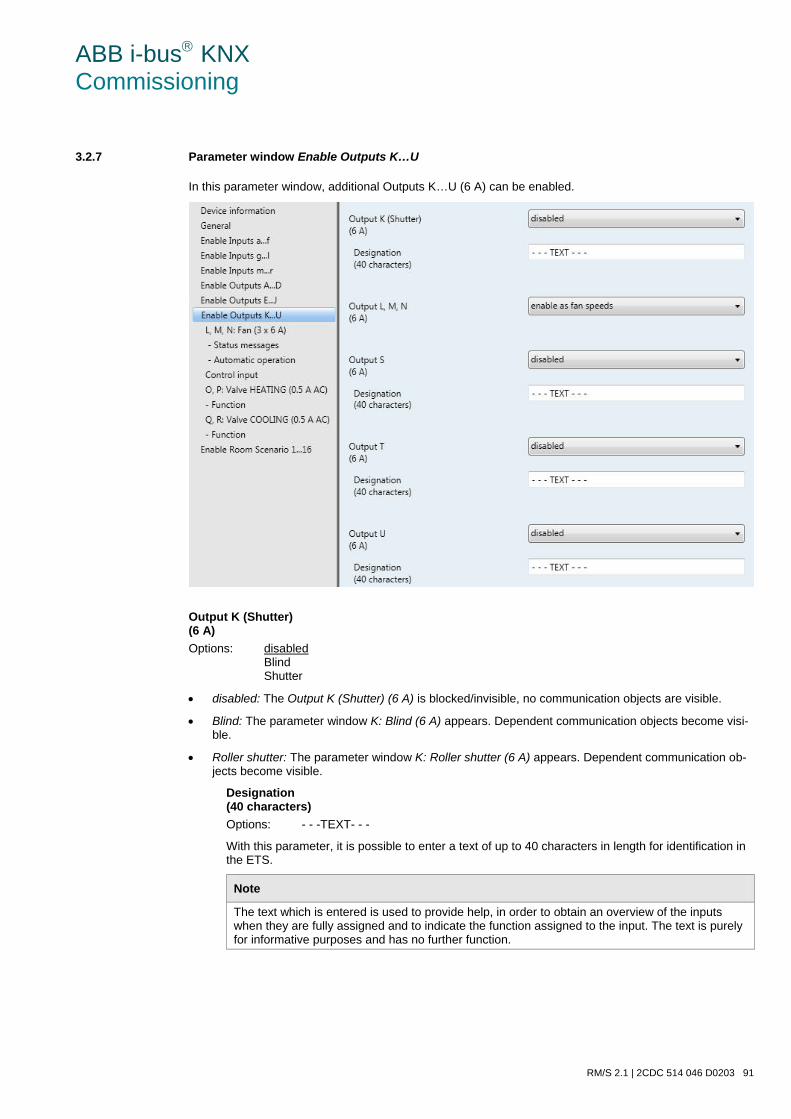
ABB i-bus KNX Commissioning
RM/S 2.1 | 2CDC 514 046 D0203 91
3.2.7 Parameter window Enable Outputs K…U
In this parameter window, additional Outputs K…U (6 A) can be enabled.
Output K (Shutter) (6 A) Options: disabled
Blind Shutter
• disabled: The Output K (Shutter) (6 A) is blocked/invisible, no communication objects are visible.
• Blind: The parameter window K: Blind (6 A) appears. Dependent communication objects become visi-ble.
• Roller shutter: The parameter window K: Roller shutter (6 A) appears. Dependent communication ob-jects become visible.
Designation (40 characters) Options: - - -TEXT- - -
With this parameter, it is possible to enter a text of up to 40 characters in length for identification in the ETS.
Note
The text which is entered is used to provide help, in order to obtain an overview of the inputs when they are fully assigned and to indicate the function assigned to the input. The text is purely for informative purposes and has no further function.
ABB i-bus KNX Commissioning
92 2CDC 514 046 D0203 | RM/S 2.1
Output L, M, N Options: enable as outputs
enable as fan speeds
The outputs L, M and N can be programmed as outputs and as fans.
• enable as outputs: The outputs L, M and N can be programmed as individual parameters and can be enabled individually.
Note
The outputs L, M, N have no Enable function Logic function.
All other parameters and their setting possibilities for the outputs L, M, N do not differentiate from those of Output A, see Parameter window A: Output (20 A/16 AX C-Load) , page 68.
• enable as fan speeds: The parameter window L, M, N: Fan (3 x 6 A) appears.
Outputs S, T, U The descriptions of the parameter setting options and the adjustable communication objects for the Out-puts S, T, U do not differ from the Output A.
However, the function Time with the Outputs S, T, U has a further adjustment option: Flashing.
Note
The function Flashing is described as an example in Parameter window E: Output - Time, Flashing, page 88. All other descriptions of the parameter can be found in Parameter window A: Output (20 A/16 AX C-Load), page 68.
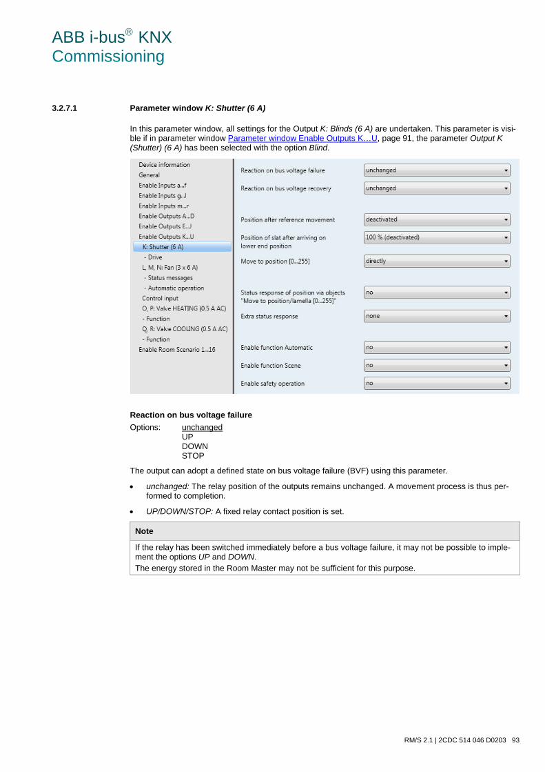
ABB i-bus KNX Commissioning
RM/S 2.1 | 2CDC 514 046 D0203 93
3.2.7.1 Parameter window K: Shutter (6 A)
In this parameter window, all settings for the Output K: Blinds (6 A) are undertaken. This parameter is visi-ble if in parameter window Parameter window Enable Outputs K…U, page 91, the parameter Output K (Shutter) (6 A) has been selected with the option Blind.
Reaction on bus voltage failure Options: unchanged
UP DOWN STOP
The output can adopt a defined state on bus voltage failure (BVF) using this parameter.
• unchanged: The relay position of the outputs remains unchanged. A movement process is thus per-formed to completion.
• UP/DOWN/STOP: A fixed relay contact position is set.
Note
If the relay has been switched immediately before a bus voltage failure, it may not be possible to imple-ment the options UP and DOWN. The energy stored in the Room Master may not be sufficient for this purpose.
ABB i-bus KNX Commissioning
94 2CDC 514 046 D0203 | RM/S 2.1
Reaction on bus voltage recovery Options: unchanged
UP DOWN STOP
This parameter defines how the output should respond with bus voltage recovery.
• unchanged: The current state is retained.
• UP/DOWN/STOP: A fixed relay contact position is set.
Position after reference movement Options: deactivated
no reaction move to saved position
This parameter enables the communication object Reference movement and defines how the Room Mas-ter responds after a reference movement. For further information see: Communication objects Output K: Blinds and shutters, page 201 • deactivated: The communication object Reference movement is not visible. No referencing can be
performed.
• no reaction: The blind remains either up or down in the reference position after the reference move-ment.
• move to saved position: The blind is retracted to the position, in which it was before the reference movement was performed. If the function Automatic was activated for the blind before the reference movement, then the function Automatic is re-activated again automatically after the saved position is reached.
Note
If during a reference movement a direct or automatic movement of position telegram is received, the reference movement is performed first, and the received target position is approached afterwards.
For further information see: Determination of the current position, page 225
Position after reference movement Options: 100 % (deactivated)
90 % … 10 % 0 %
After the blinds are moved to the end positions, the slats are normally closed. The slat positions can be set via this parameter as the Room Master is set after the lower end position is reached.
The parameter relates to the reaction of the blind, if the motion has been triggered via the communication object Blinds/Shutters UP/DOWN move or by the function Automatic.
ABB i-bus KNX Commissioning
RM/S 2.1 | 2CDC 514 046 D0203 95
Move to position [0…255] Options: directly
indirectly via up indirectly via down indirectly via shortest way
• directly: The blind moves with a position telegram from the current position directly to the new target position.
• indirectly via up/indirectly via down: The blind will initially move fully up or down after a movement tel-egram is received and then move to the target position.
• indirectly via shortest way: The blind will initially move fully up or down after a position telegram is re-ceived, depending on which path is the shortest. Thereafter the blind moves to the target position.
Status response of position via object "Move to position/slat [0…255]" Options: no
yes
This parameter defines if the communication object Move to position/Lamella [0…255] sends a status re-sponse.
• yes: The following parameter appears:
Send object value Options: no, update only
after a change after request after a change or request
• no, update only: The status is updated but not sent.
• after a change: The status is sent after a change.
• after request: The status is sent after a request.
• after a change or request: The status is sent after a change or a request.
Extra status response Options: none
end positions Status byte
An additional status response can be enabled with this parameter.
• none: There is no feedback.
• end positions: The communication objects Status of lower position and Status of upper position are enabled. These indicate that the blinds are in the upper or lower position (measured based on total movement time).
• Status byte: The communication object Status byte is enabled. This contains further information in coded form.
ABB i-bus KNX Commissioning
96 2CDC 514 046 D0203 | RM/S 2.1
Enable function Automatic Options: no
yes
• no: The parameter window remains disabled and invisible.
• yes: The parameter window - Automatic appears.
By enabling the function Automatic, the parameter window - Automatic is enabled where further settings can be made.
Enable function Scene Options: no
yes
• no: The parameter window remains disabled and invisible.
• yes: The parameter window - Scene appears.
By enabling the function Scene the parameter window - Scene is enabled where further settings can be made, e.g. the assignment of the output to a scene.
Enable Safety operation Options: no
yes
• no: The parameter window remains disabled and invisible.
• yes: The parameter window - Safety appears.
By enabling the function Safety, the parameter window - Safety is enabled, where further settings can be made.
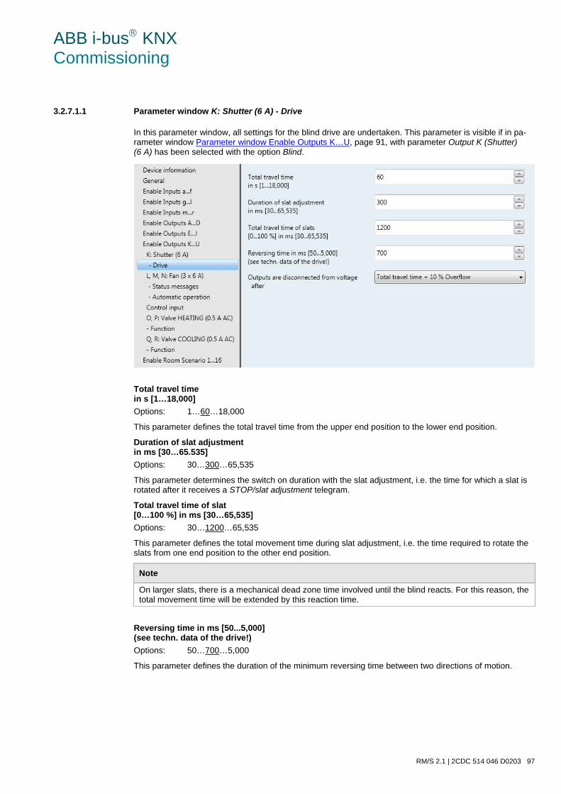
ABB i-bus KNX Commissioning
RM/S 2.1 | 2CDC 514 046 D0203 97
3.2.7.1.1 Parameter window K: Shutter (6 A) - Drive
In this parameter window, all settings for the blind drive are undertaken. This parameter is visible if in pa-rameter window Parameter window Enable Outputs K…U, page 91, with parameter Output K (Shutter) (6 A) has been selected with the option Blind.
Total travel time in s [1…18,000] Options: 1…60…18,000
This parameter defines the total travel time from the upper end position to the lower end position.
Duration of slat adjustment in ms [30…65.535] Options: 30…300…65,535
This parameter determines the switch on duration with the slat adjustment, i.e. the time for which a slat is rotated after it receives a STOP/slat adjustment telegram.
Total travel time of slat [0…100 %] in ms [30…65,535] Options: 30…1200…65,535
This parameter defines the total movement time during slat adjustment, i.e. the time required to rotate the slats from one end position to the other end position.
Note
On larger slats, there is a mechanical dead zone time involved until the blind reacts. For this reason, the total movement time will be extended by this reaction time.
Reversing time in ms [50...5,000] (see techn. data of the drive!) Options: 50…700…5,000
This parameter defines the duration of the minimum reversing time between two directions of motion.
ABB i-bus KNX Commissioning
98 2CDC 514 046 D0203 | RM/S 2.1
Outputs are disconnected from voltage after Options: End position + no overflow
End position + 2 % overflow End position + 5 % overflow End position + 10 % overflow End position + 20 % overflow Total travel time + 10 % Overflow
• End position…: The application program calculates the movement time required from the current posi-tion to the end position. After the end position has been reached (as the very top or bottom), the blind drive will switch off independently. A so-called “overflow” can be set to ensure that the Room Master safely reaches the end position. Thus the voltage still remains applied for a short time to move the drive to a defined end position in a controlled manner .
• Total travel time + 10 % Overflow: The blind drive is always activated for the set total movement time + 10 % independently of the current position of the blind.
For further information see: Travel times, page 223
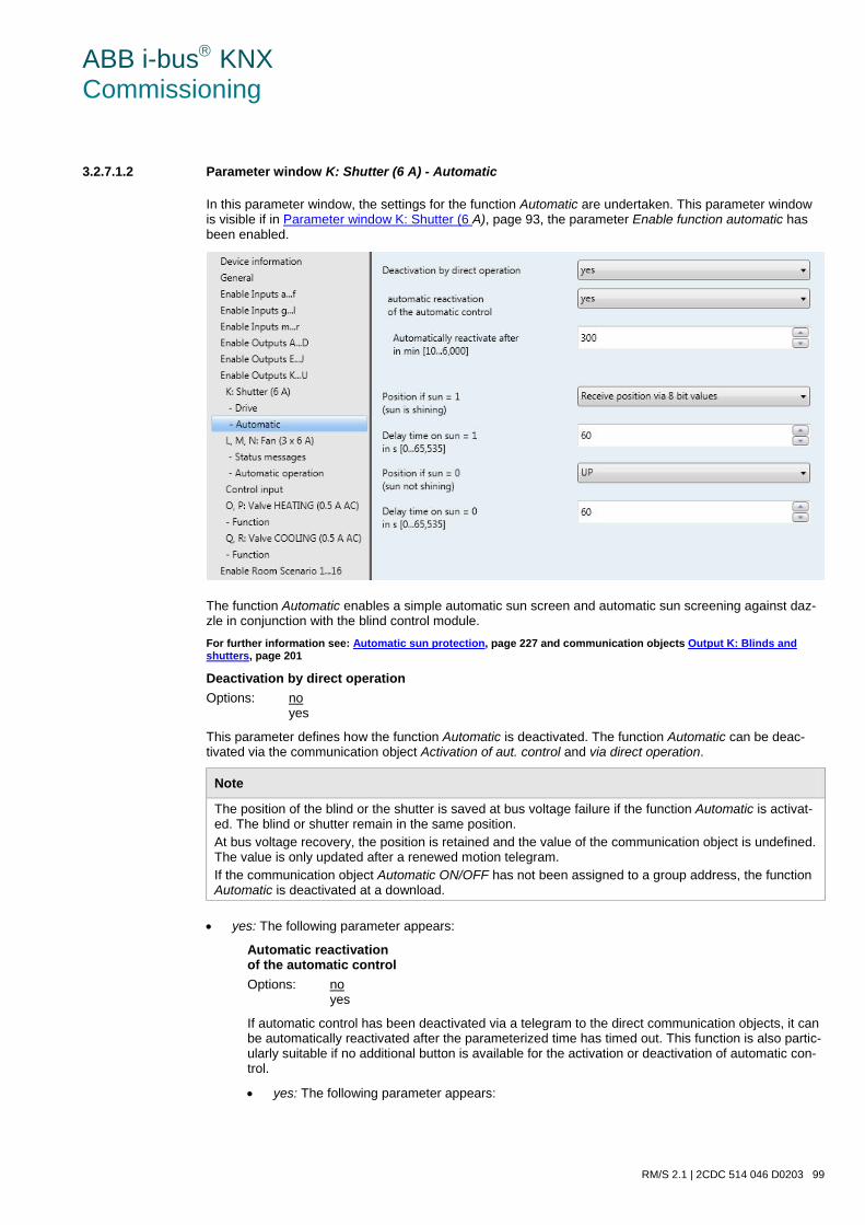
ABB i-bus KNX Commissioning
RM/S 2.1 | 2CDC 514 046 D0203 99
3.2.7.1.2 Parameter window K: Shutter (6 A) - Automatic
In this parameter window, the settings for the function Automatic are undertaken. This parameter window is visible if in Parameter window K: Shutter (6 A), page 93, the parameter Enable function automatic has been enabled.
The function Automatic enables a simple automatic sun screen and automatic sun screening against daz-zle in conjunction with the blind control module. For further information see: Automatic sun protection, page 227 and communication objects Output K: Blinds and shutters, page 201
Deactivation by direct operation Options: no
yes
This parameter defines how the function Automatic is deactivated. The function Automatic can be deac-tivated via the communication object Activation of aut. control and via direct operation.
Note
The position of the blind or the shutter is saved at bus voltage failure if the function Automatic is activat-ed. The blind or shutter remain in the same position. At bus voltage recovery, the position is retained and the value of the communication object is undefined. The value is only updated after a renewed motion telegram. If the communication object Automatic ON/OFF has not been assigned to a group address, the function Automatic is deactivated at a download.
• yes: The following parameter appears:
Automatic reactivation of the automatic control Options: no
yes
If automatic control has been deactivated via a telegram to the direct communication objects, it can be automatically reactivated after the parameterized time has timed out. This function is also partic-ularly suitable if no additional button is available for the activation or deactivation of automatic con-trol.
• yes: The following parameter appears:
ABB i-bus KNX Commissioning
100 2CDC 514 046 D0203 | RM/S 2.1
Automatically reactivate after in min [10…6,000] Options: 10…300…6,000
Using this parameter, the duration for the automatic reactivation of the automatic control is defined. If automatic control is interrupted during the parameterized time by a direct commu-nication object, the parameterized time for automatic reactivation of automatic control re-commences to count from 0 (retriggering)..
Note
A change of the parameter value will only become active after the next deactivation of au-tomatic control.
Position if sun = 1 (sun is shining) Options: no reaction
UP DOWN STOP Receive position via 8 bit values
This parameter defines the reaction with sun = 1 (sun is shining) in the automatic sun screen operation.
• no reaction: The current movement action is completed.
• UP: The blind moves UP.
• DOWN: The blind moves DOWN.
• STOP: The output is electrically disconnected, i.e. a moving blind is stopped.
• Receive position via 8 bit values: The blind moves to position by receiving an 8 bit value. For this pur-pose, the communication objects Sun: Move to position [0…255] and Sun: adjust slats [0…255] are available.
Delay time on sun = 1 in s [0…65,535] Options: 0…60…65,535
This parameter defines the delay with activation of the Position if sun = 1.
Via these parameters, for example, you can prevent that the blind moves UP and DOWN, if the sun is only overcast for a short period of time.
ABB i-bus KNX Commissioning
RM/S 2.1 | 2CDC 514 046 D0203 101
Position if sun = 0 (sun not shining) Options: no reaction
UP DOWN STOP Receive position via 8 bit values
For setting the behaviour with sun = 0 (sun not shining) in the automatic sun screen operation.
• no reaction: The current movement action is completed.
• UP: The blind moves UP.
• DOWN: The blind moves DOWN.
• STOP: The output is electrically disconnected, i.e. a moving blind is stopped.
• Receive position via 8 bit values: The blind moves to position by receiving an 8 bit value. For this pur-pose, the communication objects Sun: Move to position [0…255] and Sun: adjust slats [0…255] are available.
Delay time on sun = 0 in s [0…65,535] Options: 0…60…65,535
This parameter defines the delay with activation of the Position if sun = 0.
Via these parameters, for example, you can prevent that the blind moves UP and DOWN, if the sun is only overcast for a short period of time.
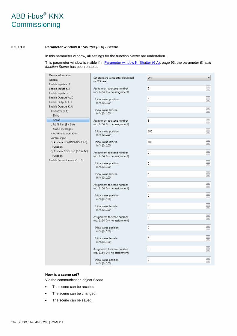
ABB i-bus KNX Commissioning
102 2CDC 514 046 D0203 | RM/S 2.1
3.2.7.1.3 Parameter window K: Shutter (6 A) - Scene
In this parameter window, all settings for the function Scene are undertaken.
This parameter window is visible if in Parameter window K: Shutter (6 A), page 93, the parameter Enable function Scene has been enabled.
How is a scene set? Via the communication object Scene
• The scene can be recalled.
• The scene can be changed.
• The scene can be saved.
ABB i-bus KNX Commissioning
RM/S 2.1 | 2CDC 514 046 D0203 103
An example: Scene recall:
• Send value 0-63 for the scene (no. 1-64) to the communication object Scene.
Scene change and save:
• Scene no. 24 is assigned to the output with the value move UP.
• Scene no. 24 should be assigned to the output with the value move DOWN.
o Set the output to move DOWN with a switch telegram.
o Send value 151 (128 + 23) for storage of scene number 24 to the communication object Scene.
General values for scene storage:
• 128 + (0…-63) for the scene (No. 1…64)
o The stored scene values are retained until there is a device reset.
Note
The stored scene values are retained with a bus voltage failure. After a device reset the parameterized scene values can be reactivated. For further information see: Reset via bus, page 258
Set standard value after the download or ETS reset Options: no
yes
• no: The standard values are not set after a download or ETS reset.
• yes: The standard values are set after a download or ETS reset.
Assignment to scene number [no. 1…64, 0 = no assignment] Options: 0…64
The scene values are undefined by default and must therefore be learned once via the bus.
Using the scene function up to 64 scenes are managed using just a single group address. With this group address, all slaves integrated into a scene are linked via a 1 byte communication object. The following in-formation is contained in a telegram:
• Number of the scene (1…64) as well as
• Telegram: Call scene or store scene.
The blind can be integrated in up to eight scenes. So for example, the blind can be switched UP via a sce-ne in the morning and switched DOWN in the evening, or the blind can be integrated into light scenes.
If a telegram is received on the communication object Scene, the sent scene number is allocated for all outputs which move to the stored scene position or the current position is stored as the new scene posi-tion. For further information see: Communication objects Output K: Blinds and shutters, page 201, Function scene, page 221 and Code table scene (8 bit), page 320

ABB i-bus KNX Commissioning
104 2CDC 514 046 D0203 | RM/S 2.1
Initial value position in % [0…100] Options: 0…100
This parameter defines the position in percent, to which the blind should be moved when the scene is called.
Initial value slat in % [0…100] Options: 0…100
This parameter defines the slat position in percent, to which the blind should be moved when the scene is called.
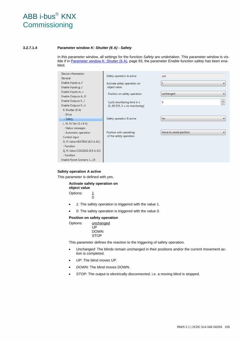
ABB i-bus KNX Commissioning
RM/S 2.1 | 2CDC 514 046 D0203 105
3.2.7.1.4 Parameter window K: Shutter (6 A) - Safety
In this parameter window, all settings for the function Safety are undertaken. This parameter window is vis-ible if in Parameter window K: Shutter (6 A), page 93, the parameter Enable function safety has been ena-bled.
Safety operation A active This parameter is defined with yes.
Activate safety operation on object value Options: 1
0
• 1: The safety operation is triggered with the value 1.
• 0: The safety operation is triggered with the value 0.
Position on safety operation Options: unchanged
UP DOWN STOP
This parameter defines the reaction to the triggering of safety operation.
• Unchanged: The blinds remain unchanged in their positions and/or the current movement ac-tion is completed.
• UP: The blind moves UP.
• DOWN: The blind moves DOWN.
• STOP: The output is electrically disconnected, i.e. a moving blind is stopped.
ABB i-bus KNX Commissioning
106 2CDC 514 046 D0203 | RM/S 2.1
Cyclic monitoring time in s [0…65,535, 0 = no monitoring] Options: 0…65,535
The parameter defines the intervals at which, the safety operation is monitored. The safety opera-tion is not monitored with the setting 0. If the communication object Safety operation A does not re-ceive a telegram after the set monitoring time, the safety is activated.
Note
The safety operation is reset if an ETS reset has occurred.
Important
On bus voltage recovery, the safety operation remains active until the enable is sent again.
Safety operation B active Options: no
yes
This parameter defines how the safety operation B is activated.
Note
The setting options for safety operation B do not differ from those of safety operation A, see above.
Position with cancelling of the safety operation. Options: unchanged
UP DOWN STOP move to saved position
This parameter defines the position, to which the shutter/blind moves after safety operation is cancelled.
• Unchanged: The blind remains unchanged in its position and/or the current movement action is com-pleted.
• UP: The blind moves UP.
• DOWN: The blind moves DOWN.
• STOP: The output is electrically disconnected, i.e. a moving blind is stopped.
• move to saved position: The blind is moved to its preset position.
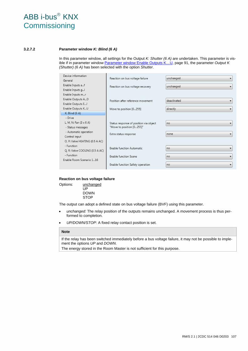
ABB i-bus KNX Commissioning
RM/S 2.1 | 2CDC 514 046 D0203 107
3.2.7.2 Parameter window K: Blind (6 A)
In this parameter window, all settings for the Output K: Shutter (6 A) are undertaken. This parameter is vis-ible if in parameter window Parameter window Enable Outputs K…U, page 91, the parameter Output K (Shutter) (6 A) has been selected with the option Shutter.
Reaction on bus voltage failure Options: unchanged
UP DOWN STOP
The output can adopt a defined state on bus voltage failure (BVF) using this parameter.
• unchanged: The relay position of the outputs remains unchanged. A movement process is thus per-formed to completion.
• UP/DOWN/STOP: A fixed relay contact position is set.
Note
If the relay has been switched immediately before a bus voltage failure, it may not be possible to imple-ment the options UP and DOWN. The energy stored in the Room Master is not sufficient for this purpose.
ABB i-bus KNX Commissioning
108 2CDC 514 046 D0203 | RM/S 2.1
Reaction on bus voltage recovery Options: unchanged
UP DOWN STOP
This parameter defines how the output should respond with bus voltage recovery.
• unchanged: The current state is retained.
• UP/DOWN/STOP: A fixed relay contact position is set.
Position after reference movement Options: deactivated
no reaction move to saved position
This parameter enables the communication object Reference movement and defines how the Room Mas-ter responds after a reference movement.
• deactivated: The communication object Reference movement is not visible. No referencing can be performed.
• no reaction: The shutter remains either up or down in the reference position after the reference movement.
• move to saved position: The shutter is retracted to the position, in which it was before the reference movement was performed. If the function Automatic was activated for the shutters before the refer-ence movement, the function Automatic is reactivated after the stored position is reached.
Note
If during a reference movement a direct or automatic movement of position telegram is received, the reference movement is performed first and the received target position is approached afterwards.
For further information see: Determination of the current position, page 225
Move to position [0…255] Options: directly
indirectly via up indirectly via down indirectly via shortest way
• directly: The shutter moves with a position telegram from the current position directly to the new target position.
• indirectly via up/indirectly via down: The shutter will initially move fully up or down, after a movement telegram is received, and then move to the target position.
• indirectly via shortest way: The shutter will initially move fully up or down, after a movement telegram is received, depending on which path is the shortest. Thereafter the shutter moves to the target posi-tion.
ABB i-bus KNX Commissioning
RM/S 2.1 | 2CDC 514 046 D0203 109
Status response of position via objects "Move to position/lamella [0…255]" Options: no
yes
This parameter defines if the communication object Move to position [0…255] sends a status response.
• yes: The following parameter appears:
Send object value Options: no, update only
after a change after request after a change or request
• no, update only: The status is updated but not sent.
• after a change: The status is sent after a change.
• after request: The status is sent after a request.
• after a change or request: The status is sent after a change or a request.
Extra status response Options: none
end positions Status byte
An additional status response can be enabled with this parameter.
• none: There is no feedback.
• end positions: The communication objects Status of lower position and Status of upper position are enabled; these indicate that the shutter/blind are in the upper or lower position (measured based on total movement time).
• Status byte: The communication object Status byte which contains further information in coded format is enabled.
Enable function Automatic Options: no
yes
• no: The parameter window remains disabled and invisible.
• yes: The parameter window - Automatic appears.
By enabling the function Automatic, the parameter window - Automatic is enabled where further settings can be made.
ABB i-bus KNX Commissioning
110 2CDC 514 046 D0203 | RM/S 2.1
Enable function Scene Options: no
yes
• no: The parameter window remains disabled and invisible.
• yes: The parameter window - Scene appears.
By enabling the function Scene the parameter window - Scene is enabled where further settings can be made, e.g. the assignment of the output to a scene.
Enable safety operation Options: no
yes
• no: The parameter window remains disabled and invisible.
• yes: The parameter window - Safety appears.
By enabling the function Safety, the parameter window - Safety is enabled, where further settings can be made.
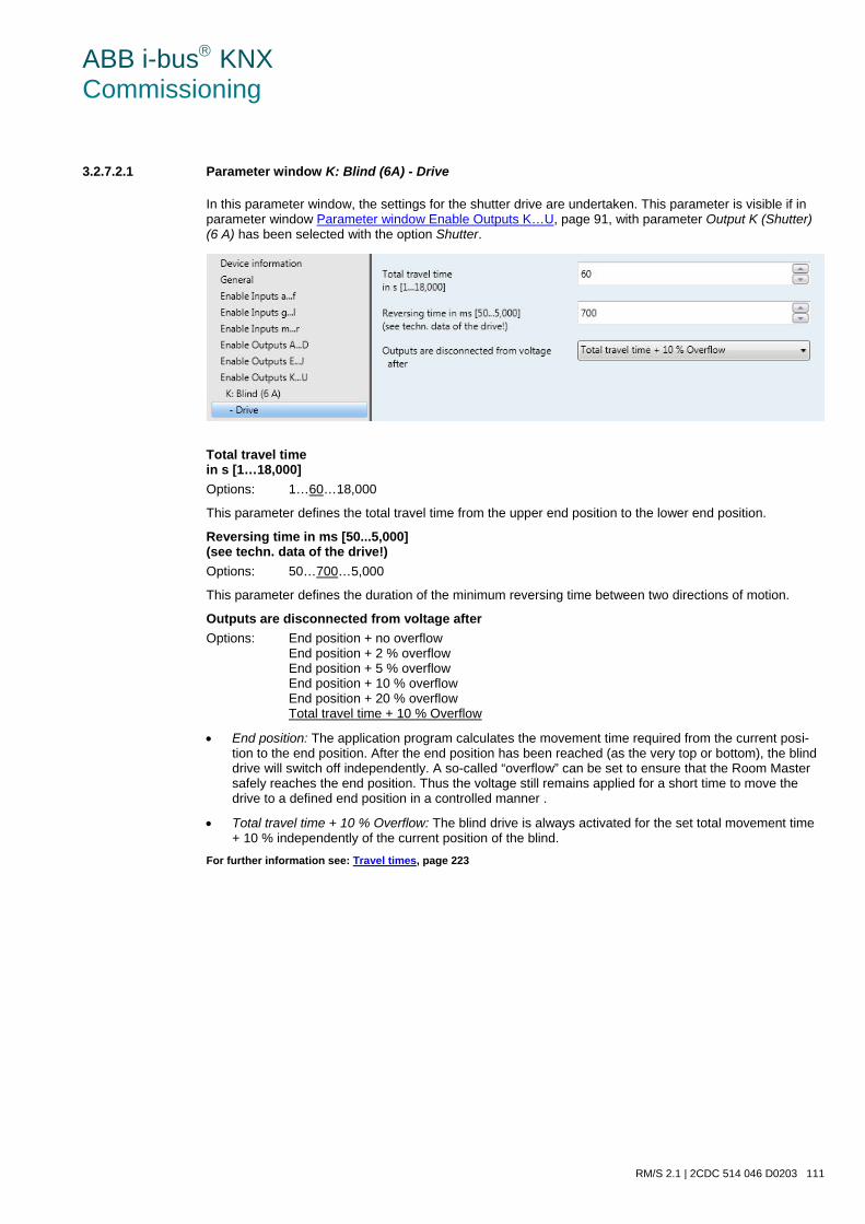
ABB i-bus KNX Commissioning
RM/S 2.1 | 2CDC 514 046 D0203 111
3.2.7.2.1 Parameter window K: Blind (6A) - Drive
In this parameter window, the settings for the shutter drive are undertaken. This parameter is visible if in parameter window Parameter window Enable Outputs K…U, page 91, with parameter Output K (Shutter) (6 A) has been selected with the option Shutter.
Total travel time in s [1…18,000] Options: 1…60…18,000
This parameter defines the total travel time from the upper end position to the lower end position.
Reversing time in ms [50...5,000] (see techn. data of the drive!) Options: 50…700…5,000
This parameter defines the duration of the minimum reversing time between two directions of motion.
Outputs are disconnected from voltage after Options: End position + no overflow
End position + 2 % overflow End position + 5 % overflow End position + 10 % overflow End position + 20 % overflow Total travel time + 10 % Overflow
• End position: The application program calculates the movement time required from the current posi-tion to the end position. After the end position has been reached (as the very top or bottom), the blind drive will switch off independently. A so-called “overflow” can be set to ensure that the Room Master safely reaches the end position. Thus the voltage still remains applied for a short time to move the drive to a defined end position in a controlled manner .
• Total travel time + 10 % Overflow: The blind drive is always activated for the set total movement time + 10 % independently of the current position of the blind.
For further information see: Travel times, page 223
ABB i-bus KNX Commissioning
112 2CDC 514 046 D0203 | RM/S 2.1
3.2.7.2.2 Parameter window K: Blind (6A) - Automatic
The function Automatic shutters does not differ from the function Automatic blinds.
The descriptions of the parameter setting options and the adjustable communication objects can be found in the Parameter window K: Shutter (6 A) - Automatic, page 99. Total travel time + 10 % Overflow: The blind drive is always activated for the set total movement time + 10 % independently of the current position of the blind. For further information see: Travel times, page 223
3.2.7.2.3 Parameter window K: Blind (6A) - Scene
The function Scene Blinds does not differ from the function Scene shutters.
The descriptions of the parameter setting options and the adjustable communication objects can be found in the Parameter window K: Shutter (6 A) - Scene, page 102.
3.2.7.2.4 Parameter window K: Blind (6A) - Safety
The function Safety Blind does not differ from the function Safety blinds.
The descriptions of the parameter setting options and the adjustable communication objects can be found in the Parameter window K: Shutter (6 A) - Safety, page 105.
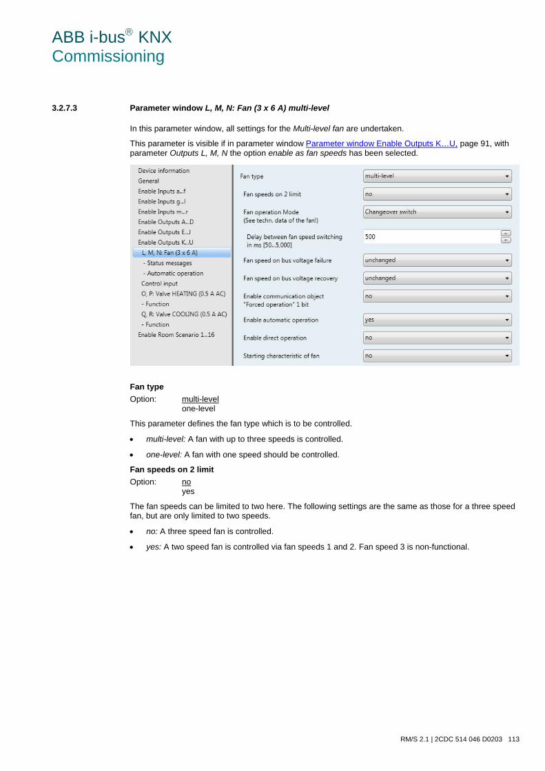
ABB i-bus KNX Commissioning
RM/S 2.1 | 2CDC 514 046 D0203 113
3.2.7.3 Parameter window L, M, N: Fan (3 x 6 A) multi-level
In this parameter window, all settings for the Multi-level fan are undertaken.
This parameter is visible if in parameter window Parameter window Enable Outputs K…U, page 91, with parameter Outputs L, M, N the option enable as fan speeds has been selected.
Fan type Option: multi-level
one-level
This parameter defines the fan type which is to be controlled.
• multi-level: A fan with up to three speeds is controlled.
• one-level: A fan with one speed should be controlled.
Fan speeds on 2 limit Option: no
yes
The fan speeds can be limited to two here. The following settings are the same as those for a three speed fan, but are only limited to two speeds.
• no: A three speed fan is controlled.
• yes: A two speed fan is controlled via fan speeds 1 and 2. Fan speed 3 is non-functional.
ABB i-bus KNX Commissioning
114 2CDC 514 046 D0203 | RM/S 2.1
Fan operation Mode (See techn. data of the fan!) Option: Changeover switch
Step switch
The control of the fan is set with this parameter. The mode of fan control should be taken from the tech-nical data of the fan.
How does a two-way changeover circuit function? Only the corresponding output of the assigned fan speed is switched on with the parameterization as a changeover switch.
The delay time between the stage switch over and a minimum dwell time in a valve stage are pro-grammable. The minimum dwell time in a fan speed is only active in automatic mode.
How does speed switching function? With step switch control, no erratic and sudden switch on of the fan is possible. The individual fan speeds are activated consecutively (outputs switched on) until the required fan speed is achieved.
The parameterized delay time between two fan speeds has the effect that the current fan speed must be switched on for at least this time before the next valve speed is switched on. The parame-terized minimum dwell time in a fan speed has the same effect as a changeover switch, i.e. it is on-ly active in automatic mode and is added to the switchover delay.
• Changeover switch: The following parameter appears:
Delay between fan speed switching in ms [50…5,000] Option: 50…500…5,000
A switchover delay can be programmed with this parameter. This time is a fan specific factor and it is always taken into consideration.
Fan speed on bus voltage failure Option: unchanged
OFF
ABB i-bus KNX Commissioning
RM/S 2.1 | 2CDC 514 046 D0203 115
Fan speed on bus voltage recovery Options: unchanged
OFF 1 2 3
• unchanged: The fan speeds of the fan remain unchanged.
• OFF: The fan is switched off.
• 1, 2 or 3: The fan switches to fan speed 1, 2 or 3.
Caution The RM/S is supplied ex-works with a default setting (factory default). This ensures that the fan setting is switched off when the bus voltage is applied to the relay for the first time. Thus, damage to the device due to unintentional switch on during transport, e.g. due to vibration, is avoided. It is advisable to apply a bus voltage before connecting the fan in order to achieve a defined switch state of the fan. This eliminates the possibility of the destruction of the fan due to an incorrect contact setting.
Enable communication object "Forced operation" 1 bit Options: no
yes
Through forced operation for example, a recirculation: valve OFF and fan ON can be implemented.
• yes: A 1 bit Forced operation communication object is enabled. The following parameters appear:
Forced operation on object value Options: 1
0
• 1: Forced operation is activated by a telegram with value 1.
• 0: Forced operation is activated by a telegram with value 0.
Note
During forced operation the settings set in Automatic operation are ignored. Automatic operation is updated after forced operation has been rescinded.
Important
Forced operation remains active until: • the complementary set values are sent. • the assignment is changed. • the fan type is changed. The Forced operation is not deactivated by a download of the application program, in which the fan type and the respective group addresses are retained. The Forced operation is reset if an ETS reset has occurred.
ABB i-bus KNX Commissioning
116 2CDC 514 046 D0203 | RM/S 2.1
Limitation on forced operation Options: 3, 2, 1, OFF
Unchanged OFF 1 1, OFF 2 2, 1 2, 1, OFF 3 3, 2 3, 2, 1
This parameter sets which fan speed is set with active forced operation or which may not be ex-ceeded or undershot.
• 3, 2, 1, OFF: Everything is possible.
• Unchanged: The state is retained.
• OFF: Off.
• 1: limited to speed 1.*
• 1, OFF limited to speed 1 and off.
• 2: limited to speed 2.*
• 2, 1: limited to speed 2 and 1.
• 2, 1, OFF: limited to speed 2, 1 and off.
• 3: limited to speed 3.*
• 3, 2: limited to speed 3 and 2.
• 3, 2, 1: limited to speed 3, 2 and 1. * The control value is ignored.
Enable automatic operation Options: no
yes
• yes: The Automatic operation is enabled. Furthermore, the Parameter window - Automatic operation, page 122, appears.
Enable direct operation Options: no
yes
• yes: Direct operation is enabled. Furthermore Parameter window - Direct operation, page 129 ap-pears.
ABB i-bus KNX Commissioning
RM/S 2.1 | 2CDC 514 046 D0203 117
Starting characteristic of fan Options: no
yes
This parameter enables the fan to start from the OFF state with a defined fan speed. This fan stage is im-mediately applied.
In order to guarantee a safe start of the fan motor, it can be useful to start the fan motor first with a higher fan speed. Thus a higher torque for the start up phase of the fan is achieved.
Note
A step switch normally means however that the previous fan stages are usually switched on consecu-tively. With the changeover switch the fan speed is directly switched on.
The delay between the switchover of two fan speeds (contact change) is considered.
The dwell times in a fan speed, which are considered in automatic mode, are inactive and will only be con-sidered after the start up phase.
The start-up behaviour is a technical characteristic of the fan. For this reason, this behaviour has a higher priority than an active limitation or forced operation.
With the option yes in the parameter Starting characteristic of fan, the two additional parameters appear:
Switch on over fan speed Options: 1/2/3
Here you set which fan stage the fan uses to start from the OFF state.
Minimum dwell period in switch on in s [1…65,535] Options: 1…5…65,535
This parameter defines the minimum dwell time for one of the switch on speeds.
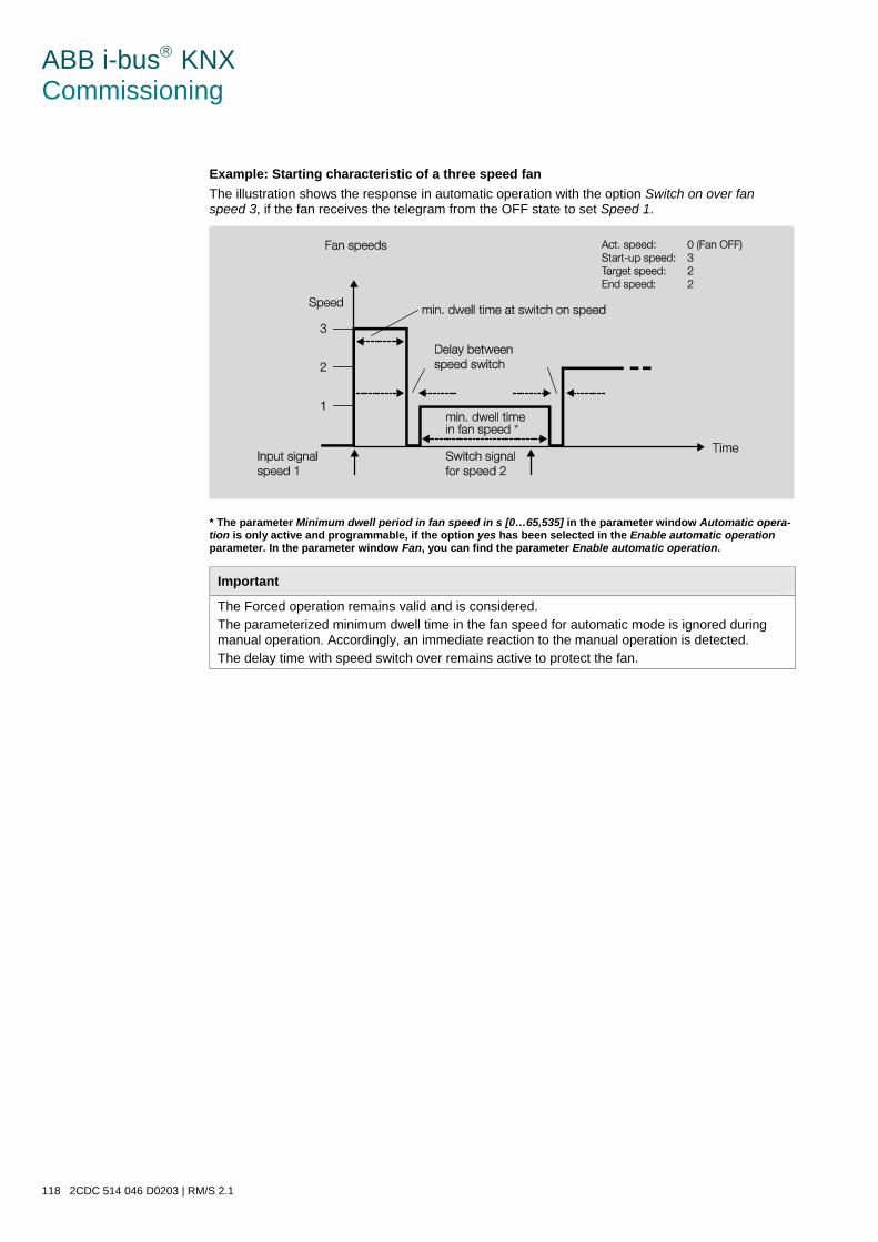
ABB i-bus KNX Commissioning
118 2CDC 514 046 D0203 | RM/S 2.1
Example: Starting characteristic of a three speed fan The illustration shows the response in automatic operation with the option Switch on over fan speed 3, if the fan receives the telegram from the OFF state to set Speed 1.
* The parameter Minimum dwell period in fan speed in s [0…65,535] in the parameter window Automatic opera-tion is only active and programmable, if the option yes has been selected in the Enable automatic operation parameter. In the parameter window Fan, you can find the parameter Enable automatic operation.
Important
The Forced operation remains valid and is considered. The parameterized minimum dwell time in the fan speed for automatic mode is ignored during manual operation. Accordingly, an immediate reaction to the manual operation is detected. The delay time with speed switch over remains active to protect the fan.
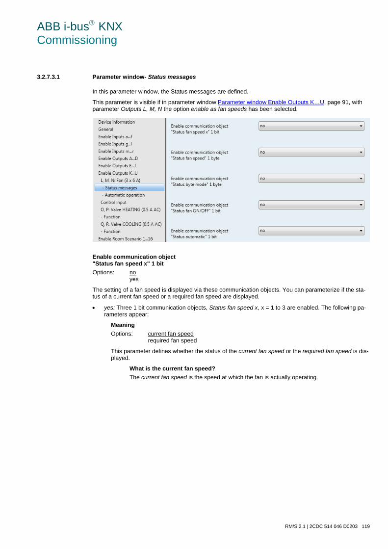
ABB i-bus KNX Commissioning
RM/S 2.1 | 2CDC 514 046 D0203 119
3.2.7.3.1 Parameter window- Status messages
In this parameter window, the Status messages are defined.
This parameter is visible if in parameter window Parameter window Enable Outputs K…U, page 91, with parameter Outputs L, M, N the option enable as fan speeds has been selected.
Enable communication object "Status fan speed x" 1 bit Options: no
yes
The setting of a fan speed is displayed via these communication objects. You can parameterize if the sta-tus of a current fan speed or a required fan speed are displayed.
• yes: Three 1 bit communication objects, Status fan speed x, x = 1 to 3 are enabled. The following pa-rameters appear:
Meaning Options: current fan speed
required fan speed
This parameter defines whether the status of the current fan speed or the required fan speed is dis-played.
What is the current fan speed? The current fan speed is the speed at which the fan is actually operating.
ABB i-bus KNX Commissioning
120 2CDC 514 046 D0203 | RM/S 2.1
What is the required fan speed? The required fan speed is the fan speed which has to be achieved, e.g. when the transition and dwell times are completed.
Note
The limitations are included in this observation, i.e. if a limitation allows only fan speed 2, the fan is operating at fan speed 2, and, for example, a telegram to switch up is received, the required fan speed remains at 2, as fan speed 3 cannot be achieved due to the limita-tion.
Send object values Options: no, update only
after a change after request after a change or request
• no, update only: The status is updated but not sent.
• after a change: The status is sent after a change.
• after request: The status is sent after a request.
• after a change or request: The status is sent after a change or a request.
Enable communication object "Status fan speed" 1 byte Options: no
yes
This status byte defines the figure value of the fan speed.
This display can be differentiated with the selection of current fan speed from the required fan speed. Ini-tially, the switchover times, dwell times and the start-up phase must be completed before the required fan speed is achieved.
• yes: The communication object Status fan speed is enabled.
What is the current fan speed? The current fan speed is the speed at which the fan is actually operating.
What is the required fan speed? The required fan speed is the fan speed which has to be achieved, e.g. when the transition and dwell times are completed.
With option yes, the following parameters appear:
Meaning Options: current fan speed
required fan speed
This parameter defines whether the status of the current fan speed or the required fan speed is dis-played.
Note
The limitations are included in this observation, i.e. if a limitation allows only fan speed 2, the fan is operating at fan speed 2, and, for example, a telegram to switch up is received, the required fan speed remains at 2, as fan speed 3 cannot be achieved due to the limitation.
ABB i-bus KNX Commissioning
RM/S 2.1 | 2CDC 514 046 D0203 121
Send object value Options: no, update only
after a change after request after a change or request
• no, update only: The status is updated but not sent.
• after a change: The status is sent after a change.
• after request: The status is sent after a request.
• after a change or request: The status is sent after a change or a request.
Enable communication object "Status byte mode" 1 byte Options: no
yes
From this status byte, the states HEATING, COOLING, automatic, forced operation and the four limitations are indicated directly via a 1 bit coding. For further information see: Status byte fan, forced/operation, page 318 • yes: The communication object Status byte mode is enabled. The following parameter appears:
Send object values Options: no, update only
after a change after request after a change or request
• no, update only: The status is updated but not sent.
• after a change: The status is sent after a change.
• after request: The status is sent after a request.
• after a change or request: The status is sent after a change or a request.
Enable communication object "Status fan ON/OFF" 1 bit' Options: no
yes
The communication object Status fan can be enabled with this parameter.
Some fans initially need an ON telegram before they are set to a fan speed from the OFF state. This ON telegram has effect on a main switch which has to be switched on. This demand can be implemented with any switch output which is controlled via the Status fan communication object. The corresponding switch communication object of the switch actuator should be connected with the Status fan communication ob-ject.
With option yes the following parameters appear:
ABB i-bus KNX Commissioning
122 2CDC 514 046 D0203 | RM/S 2.1
Send object value Options: no, update only
after a change after request after a change or request
• no, update only: The status is updated but not sent.
• after a change: The status is sent after a change.
• after request: The status is sent after a request.
• after a change or request: The status is sent after a change or a request.
The following parameter only becomes visible if the option yes has been selected in the Enable automatic operation parameter in the Fan parameter window.
Enable communication object "Status automatic" 1 bit Options: no
yes
The communication object Status automatic is enabled with this parameter.
Telegram value 1 = Room Master is in automatic operation. 0 = Automatic operation is switched off.
• yes: The following parameter appears:
Send object value Options: no, update only
after a change after request after a change or request
• no, update only: The status is updated but not sent.
• after a change: The status is sent after a change.
• after request: The status is sent after a request.
• after a change or request: The status is sent after a change or a request.
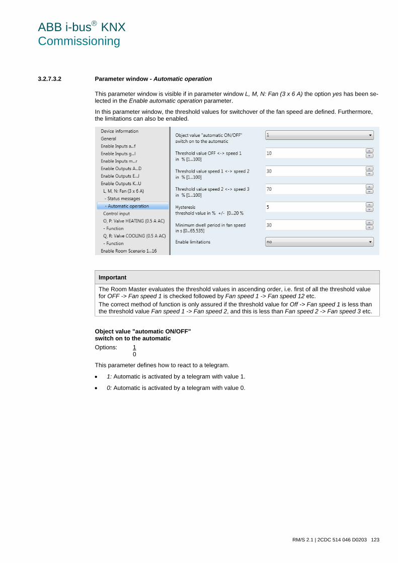
ABB i-bus KNX Commissioning
RM/S 2.1 | 2CDC 514 046 D0203 123
3.2.7.3.2 Parameter window - Automatic operation
This parameter window is visible if in parameter window L, M, N: Fan (3 x 6 A) the option yes has been se-lected in the Enable automatic operation parameter.
In this parameter window, the threshold values for switchover of the fan speed are defined. Furthermore, the limitations can also be enabled.
Important
The Room Master evaluates the threshold values in ascending order, i.e. first of all the threshold value for OFF -> Fan speed 1 is checked followed by Fan speed 1 -> Fan speed 12 etc. The correct method of function is only assured if the threshold value for Off -> Fan speed 1 is less than the threshold value Fan speed 1 -> Fan speed 2, and this is less than Fan speed 2 -> Fan speed 3 etc.
Object value "automatic ON/OFF" switch on to the automatic Options: 1
0
This parameter defines how to react to a telegram.
• 1: Automatic is activated by a telegram with value 1.
• 0: Automatic is activated by a telegram with value 0.
ABB i-bus KNX Commissioning
124 2CDC 514 046 D0203 | RM/S 2.1
Threshold value OFF <-> speed 1 in % [1...100]
Options: 1…10…100
Here the threshold value, at which switch on of fan speed 1 occurs, is set. If the value in the control value communication object is greater than the parameterized threshold value, fan speed 1 is switched on. If the value is less, it is switched off.
Threshold value speed 1 <-> speed 2 in % [1...100]
Options: 1…30…100
Here the threshold value, at which switch over to fan speed 2 occurs, is set. If the value in the control val-ue communication object is greater than the parameterized threshold value, switch over to fan speed 2 oc-curs.
Threshold value speed 2 <-> speed 3 in % [1...100]
Options: 1…70…100
Here the threshold value, at which switch over to fan speed 3 occurs, is set. If the value in the communica-tion object Control value HEATING or Control value COOLING is greater than the parameterized threshold value, switch over to fan speed 3 occurs.
Hysteresis threshold value in % +/- [0…20 %]
Options: 0…5…20
Here a hysteresis, at which switchover to the next fan speed occurs, is set. The hysteresis applies for all three threshold values.
The setting 0 causes immediate switching without hysteresis.
The entered percentage value is directly added to or subtracted from the percentage value of the Fan speed x threshold value x. The result is a new upper or lower threshold value.
Switch threshold top (switch on) = threshold value + hysteresis
Switch threshold bottom (switch off) = threshold value - hysteresis
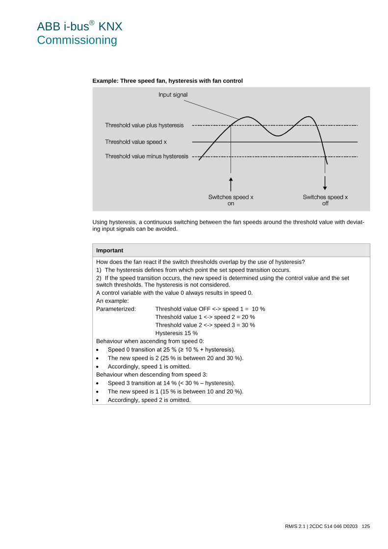
ABB i-bus KNX Commissioning
RM/S 2.1 | 2CDC 514 046 D0203 125
Example: Three speed fan, hysteresis with fan control
Using hysteresis, a continuous switching between the fan speeds around the threshold value with deviat-ing input signals can be avoided.
Important
How does the fan react if the switch thresholds overlap by the use of hysteresis? 1) The hysteresis defines from which point the set speed transition occurs. 2) If the speed transition occurs, the new speed is determined using the control value and the set switch thresholds. The hysteresis is not considered. A control variable with the value 0 always results in speed 0. An example: Parameterized: Threshold value OFF <-> speed 1 = 10 % Threshold value 1 <-> speed 2 = 20 % Threshold value 2 <-> speed 3 = 30 % Hysteresis 15 % Behaviour when ascending from speed 0: • Speed 0 transition at 25 % (≥ 10 % + hysteresis). • The new speed is 2 (25 % is between 20 and 30 %). • Accordingly, speed 1 is omitted. Behaviour when descending from speed 3: • Speed 3 transition at 14 % (< 30 % – hysteresis). • The new speed is 1 (15 % is between 10 and 20 %). • Accordingly, speed 2 is omitted.
ABB i-bus KNX Commissioning
126 2CDC 514 046 D0203 | RM/S 2.1
Minimum dwell period in fan speed in s [0...65,535] Options: 0…30…65,535
This parameter defines the dwell time for a fan speed of the fan until it switches to the next higher or lower fan speed. The input is made in seconds.
A setting of 0 means non-delayed switching. The minimum switch times of the relay can be found in the Technical data, on page 15.
The dwell time in a fan stage is only considered in automatic mode.
Enable limitations Options: no
yes
• yes: The following parameters appear:
At the same time 4 communication objects for limitation of the fan speed are enabled:
• Limitation 1, e.g. for frost/heat protection
• Limitation 2, e.g. for comfort operation
• Limitation 3, e.g. for night shutdown
• Limitation 4, e.g. for standby operation
Speed ranges (limitations) are defined for the fan with the function Speed limitation which may not be exceeded or undershot.
Four limitations are available. They can be used, for example, for the control of various operating modes, e.g. frost/heat protection, comfort, night shut down and standby. In normal cases, the ther-mostat takes these operating modes into account in its control variable for the actuator.
Important
The parameterized starting behaviour, which is a technical characteristic of the fan, has a higher priority than a limitation or forced operation, i.e. if a limitation is activated in fan speed 2 and a start-up behaviour is parameterized via fan speed 3, the following behaviour will result: The fan is in the OFF state and receives a control signal for fan speed 1. Initially the fan operates at fan speed 3 (start-up speed) and then proceeds to fan speed 2 that is defined by the limitation. The actual required fan speed 1 will not be achieved due to the limitation.
The sequence of the displayed parameters corresponds with their priorities, i.e. the parameter with the highest priority has limitation 1 followed by limitation 2, 3 and 4.
Note
The fault operation, e.g. as with a malfunction of the thermostat has a lower priority than the fan limita-tion, i.e. by a limitation of the fan speed during a thermostat malfunction, only the upper or the lower lim-it of the fan limitation can be set at best.
ABB i-bus KNX Commissioning
RM/S 2.1 | 2CDC 514 046 D0203 127
When automatic mode is exited, e.g. by a manual action, the limitations 1 to 4 are inactive.
The set limitations are reactivated after automatic operation is reactivated.
The following points apply for limitations:
• The fan speed and valve position can be parameterized independently.
• The limitation need not necessarily apply to one fan speed only. It can also encompass another range of the fan speeds, i.e. only certain fan speeds can be set if the limitation is active. In this way, a limited control is also possible.
• The limitation is activated if a telegram with the value 1 is received on the limitation communication object. The limitation is deactivated if a telegram with the value 0 is received on the limitation commu-nication object. A manual action ends automatic mode.
• If a limitation is activated, the Room Master switches to the parameterized fan speed regardless of the control value. If during the activation of the limitation another fan stage or a fan stage outside the range of the “limitation range” is set, the required fan stage or the limit fan stage of the range is set.
• After switch off of the limitations, the fan speed and the communication objects for valve control are recalculated and executed. This means that during limitation the Room Master operates normally in the background, the outputs are not changed, and implementation only occurs after the end of limita-tion.
There are the same parameters for each of the individual four limitations used to limit the fan speeds.
Important
The priority is according to the listed sequence. The highest priority is assigned to limitation 1, e.g. Frost/Heat protection; the lowest priority is assigned to limitation 4, e.g. standby operation.
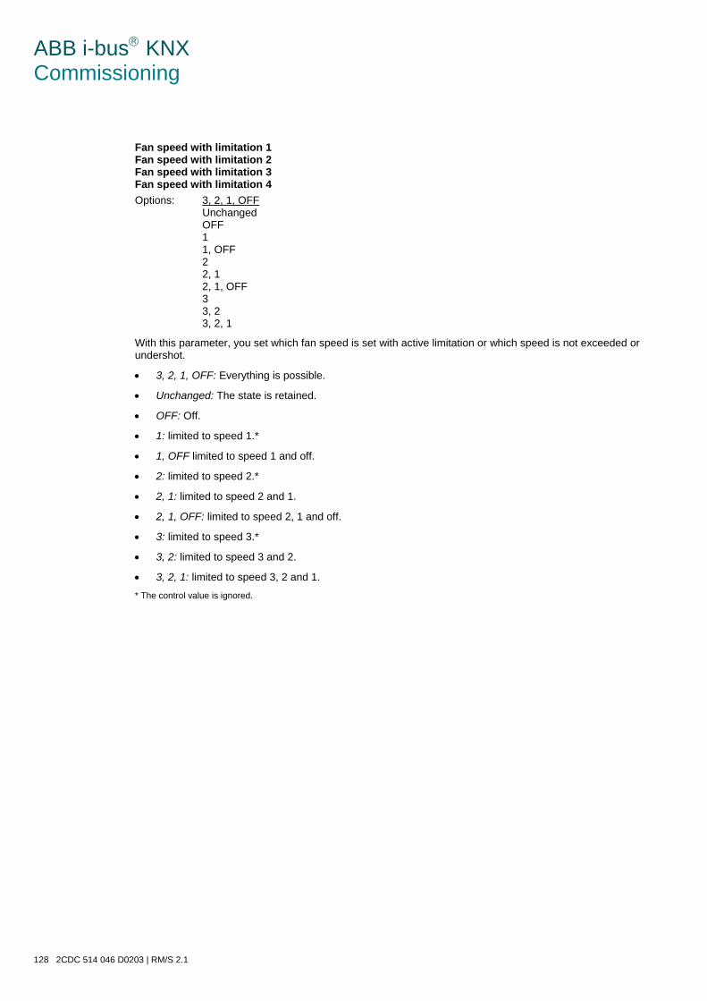
ABB i-bus KNX Commissioning
128 2CDC 514 046 D0203 | RM/S 2.1
Fan speed with limitation 1 Fan speed with limitation 2 Fan speed with limitation 3 Fan speed with limitation 4 Options: 3, 2, 1, OFF
Unchanged OFF 1 1, OFF 2 2, 1 2, 1, OFF 3 3, 2 3, 2, 1
With this parameter, you set which fan speed is set with active limitation or which speed is not exceeded or undershot.
• 3, 2, 1, OFF: Everything is possible.
• Unchanged: The state is retained.
• OFF: Off.
• 1: limited to speed 1.*
• 1, OFF limited to speed 1 and off.
• 2: limited to speed 2.*
• 2, 1: limited to speed 2 and 1.
• 2, 1, OFF: limited to speed 2, 1 and off.
• 3: limited to speed 3.*
• 3, 2: limited to speed 3 and 2.
• 3, 2, 1: limited to speed 3, 2 and 1.
* The control value is ignored.
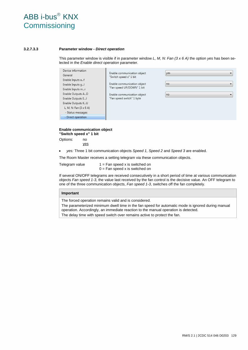
ABB i-bus KNX Commissioning
RM/S 2.1 | 2CDC 514 046 D0203 129
3.2.7.3.3 Parameter window - Direct operation
This parameter window is visible if in parameter window L, M, N: Fan (3 x 6 A) the option yes has been se-lected in the Enable direct operation parameter.
Enable communication object "Switch speed x" 1 bit Options: no
yes
• yes: Three 1 bit communication objects Speed 1, Speed 2 and Speed 3 are enabled.
The Room Master receives a setting telegram via these communication objects.
Telegram value 1 = Fan speed x is switched on 0 = Fan speed x is switched on
If several ON/OFF telegrams are received consecutively in a short period of time at various communication objects Fan speed 1-3, the value last received by the fan control is the decisive value. An OFF telegram to one of the three communication objects, Fan speed 1-3, switches off the fan completely.
Important
The forced operation remains valid and is considered. The parameterized minimum dwell time in the fan speed for automatic mode is ignored during manual operation. Accordingly, an immediate reaction to the manual operation is detected. The delay time with speed switch over remains active to protect the fan.
ABB i-bus KNX Commissioning
130 2CDC 514 046 D0203 | RM/S 2.1
Enable communication object "Fan speed UP/DOWN" 1 bit Options: no
yes
• yes: A communication object 1 bit Fan speed UP/DOWN is enabled.
Telegram value 1 = a fan speed is switched UP 0 = a fan speed is switched DOWN
If the maximum fan speed is achieved and a further telegram with the value 1 is received the fans speed will remain as it is.
Important
The forced operation remains valid and is considered. The parameterized minimum dwell time in the fan speed for automatic mode is ignored during manual operation. Accordingly, an immediate reaction to the manual operation is detected. The delay time with speed switch over remains active to protect the fan.
With multiple manual UP or DOWN switching, the target speed will be increased or reduced by a speed step. This is possible until the maximum or minimum possible speed is achieved. Further UP or DOWN telegrams are ignored and not executed. Each new switching telegram initiates a new calculation of the target speed. This means that the target speed can be changed by switching telegrams until the target speed is achieved.
Enable communication object "Fan speed switch" 1 byte Options: no
yes
• yes: A 1 byte communication object Switch speed is enabled.
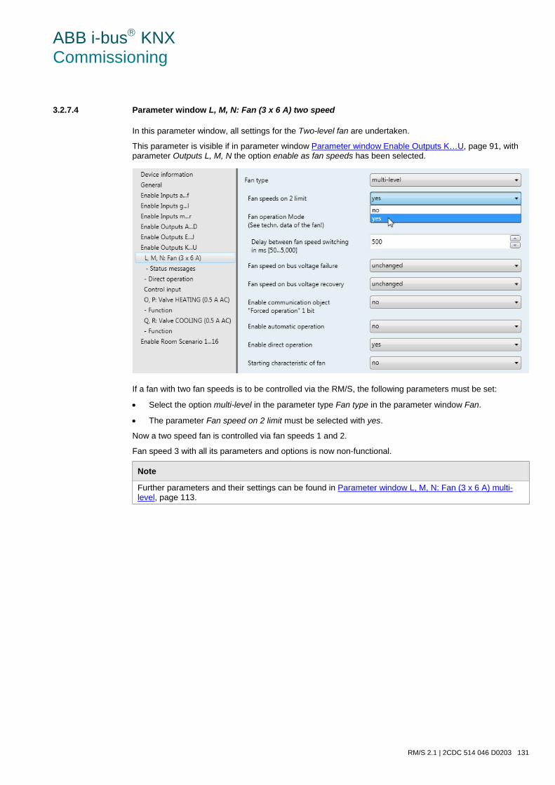
ABB i-bus KNX Commissioning
RM/S 2.1 | 2CDC 514 046 D0203 131
3.2.7.4 Parameter window L, M, N: Fan (3 x 6 A) two speed
In this parameter window, all settings for the Two-level fan are undertaken.
This parameter is visible if in parameter window Parameter window Enable Outputs K…U, page 91, with parameter Outputs L, M, N the option enable as fan speeds has been selected.
If a fan with two fan speeds is to be controlled via the RM/S, the following parameters must be set:
• Select the option multi-level in the parameter type Fan type in the parameter window Fan.
• The parameter Fan speed on 2 limit must be selected with yes.
Now a two speed fan is controlled via fan speeds 1 and 2.
Fan speed 3 with all its parameters and options is now non-functional.
Note
Further parameters and their settings can be found in Parameter window L, M, N: Fan (3 x 6 A) multi-level, page 113.
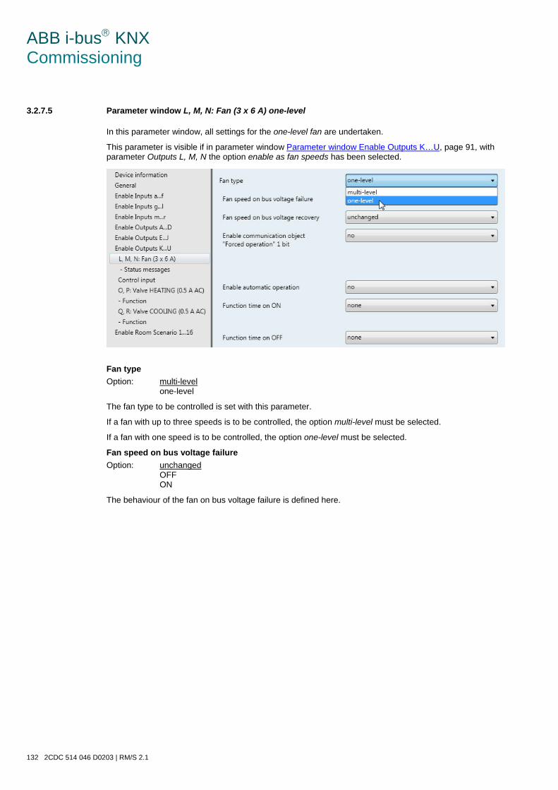
ABB i-bus KNX Commissioning
132 2CDC 514 046 D0203 | RM/S 2.1
3.2.7.5 Parameter window L, M, N: Fan (3 x 6 A) one-level
In this parameter window, all settings for the one-level fan are undertaken.
This parameter is visible if in parameter window Parameter window Enable Outputs K…U, page 91, with parameter Outputs L, M, N the option enable as fan speeds has been selected.
Fan type Option: multi-level
one-level
The fan type to be controlled is set with this parameter.
If a fan with up to three speeds is to be controlled, the option multi-level must be selected.
If a fan with one speed is to be controlled, the option one-level must be selected.
Fan speed on bus voltage failure Option: unchanged
OFF ON
The behaviour of the fan on bus voltage failure is defined here.
ABB i-bus KNX Commissioning
RM/S 2.1 | 2CDC 514 046 D0203 133
Fan speed on bus voltage recovery Options: unchanged
OFF ON
The behaviour of the fan on bus voltage recovery is defined here.
• unchanged: The fan speed of the fan remains unchanged.
• OFF: The fan is switched off.
• ON: The fan is switched on.
Caution The RM/S is supplied ex-works with a default setting (factory default). This ensures that the fan setting is switched off when the bus voltage is applied to the relay for the first time. Thus, damage to the device due to unintentional switch on during transport, e.g. due to vibration, is avoided. It is advisable to apply a bus voltage before connecting the fan in order to achieve a defined switch state of the fan. This eliminates the possibility of the destruction of the fan due to an incorrect contact setting.
Enable communication object "Forced operation" 1 bit Options: no
yes
• yes: A 1 bit Forced operation communication object is enabled. The following parameters appear at the same time:
Forced operation on object value Options: 1
0
• 1: Forced operation is activated by a telegram with value 1.
• 0: Forced operation is activated by a telegram with value 0.
Behaviour with forced operation Options: unchanged
OFF ON
This parameter defines how the fan should respond with forced operation.
ABB i-bus KNX Commissioning
134 2CDC 514 046 D0203 | RM/S 2.1
Enable automatic operation Options: no
yes
• yes: Automatic mode is enabled; an additional parameter window Automatic operation appears.
Function time on ON Options: none
switching delay minimum time
The function Time at fan ON is defined here.
• none: No function Time is executed.
• switching delay: The fan is switched on using this delay.
• minimum time: The fan remains ON for at least this time.
With option switching delay, the following parameters appear:
Time in s [1…65,535 x 0.1] Options: 1…20…65,535
The fan is switched on using this delay.
With option minimum time, the following parameters appear:
Time in s [1…65,535] Options: 1…20…65,535
The fan remains ON for at least this time.
Function time on OFF Options: none
switching delay minimum time
The function Time at fan OFF is defined here.
• none: No function Time is executed.
• switching delay: The fan is switched off using this delay.
• minimum time: The fan remains OFF for at least this time.
With option switching delay, the following parameters appear:
Time in s [1…65,535 x 0.1] Options: 1…20…65,535
The fan is switched off using this delay.
With option minimum time, the following parameters appear:
Time in s [1…65,535] Options: 1…20…65,535
The fan remains OFF for at least this time.
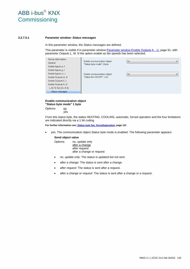
ABB i-bus KNX Commissioning
RM/S 2.1 | 2CDC 514 046 D0203 135
3.2.7.5.1 Parameter window- Status messages
In this parameter window, the Status messages are defined.
This parameter is visible if in parameter window Parameter window Enable Outputs K…U, page 91, with parameter Outputs L, M, N the option enable as fan speeds has been selected.
Enable communication object "Status byte mode" 1 byte Options: no
yes
From this status byte, the states HEATING, COOLING, automatic, forced operation and the four limitations are indicated directly via a 1 bit coding. For further information see: Status byte fan, forced/operation, page 121
• yes: The communication object Status byte mode is enabled. The following parameter appears:
Send object value Options: no, update only
after a change after request after a change or request
• no, update only: The status is updated but not sent.
• after a change: The status is sent after a change.
• after request: The status is sent after a request.
• after a change or request: The status is sent after a change or a request.
ABB i-bus KNX Commissioning
136 2CDC 514 046 D0203 | RM/S 2.1
Enable communication object "Status fan ON/OFF" 1 bit' Options: no
yes
The communication object Status fan can be enabled with this parameter.
Some fans initially require an ON telegram before they are set to a fan speed from the OFF state. This ON telegram has effect on a main switch which has to be switched on. This demand can be implemented with any switch output that is controlled via the Status fan communication object. The corresponding switch communication object of the switch actuator should be connected with the Status fan communication ob-ject.
With the option yes, the following parameters appear:
Send object value Options: no, update only
after a change after request after a change or request
• no, update only: The status is updated but not sent.
• after a change: The status is sent after a change.
• after request: The status is sent after a request.
• after a change or request: The status is sent after a change or a request.
The following parameter only appears if in parameter window L, M, N: Fan (3 x 6 A), the parameter Enable automatic operation has been selected with the option yes:
Enable communication object "Status automatic" 1 bit Options: no
yes
The communication object Status automatic is enabled with this parameter.
Telegram value 1 = automatic operation active 0 = automatic operation inactive
• yes: The following parameter appears:
Send object value Options: no, update only
after a change after request after a change or request
• no, update only: The status is updated but not sent.
• after a change: The status is sent after a change.
• after request: The status is sent after a request.
• after a change or request: The status is sent after a change or a request.
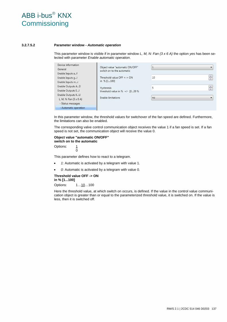
ABB i-bus KNX Commissioning
RM/S 2.1 | 2CDC 514 046 D0203 137
3.2.7.5.2 Parameter window - Automatic operation
This parameter window is visible if in parameter window L, M, N: Fan (3 x 6 A) the option yes has been se-lected with parameter Enable automatic operation.
In this parameter window, the threshold values for switchover of the fan speed are defined. Furthermore, the limitations can also be enabled.
The corresponding valve control communication object receives the value 1 if a fan speed is set. If a fan speed is not set, the communication object will receive the value 0.
Object value "automatic ON/OFF" switch on to the automatic Options: 1
0
This parameter defines how to react to a telegram.
• 1: Automatic is activated by a telegram with value 1.
• 0: Automatic is activated by a telegram with value 0.
Threshold value OFF -> ON in % [1...100] Options: 1…10…100
Here the threshold value, at which switch on occurs, is defined. If the value in the control value communi-cation object is greater than or equal to the parameterized threshold value, it is switched on. If the value is less, then it is switched off.
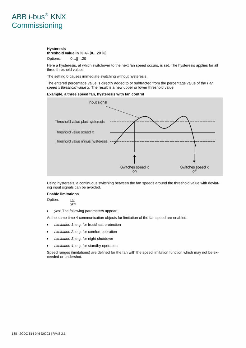
ABB i-bus KNX Commissioning
138 2CDC 514 046 D0203 | RM/S 2.1
Hysteresis threshold value in % +/- [0…20 %] Options: 0…5…20
Here a hysteresis, at which switchover to the next fan speed occurs, is set. The hysteresis applies for all three threshold values.
The setting 0 causes immediate switching without hysteresis.
The entered percentage value is directly added to or subtracted from the percentage value of the Fan speed x threshold value x. The result is a new upper or lower threshold value.
Example, a three speed fan, hysteresis with fan control
Using hysteresis, a continuous switching between the fan speeds around the threshold value with deviat-ing input signals can be avoided.
Enable limitations Option: no
yes
• yes: The following parameters appear:
At the same time 4 communication objects for limitation of the fan speed are enabled:
• Limitation 1, e.g. for frost/heat protection
• Limitation 2, e.g. for comfort operation
• Limitation 3, e.g. for night shutdown
• Limitation 4, e.g. for standby operation
Speed ranges (limitations) are defined for the fan with the speed limitation function which may not be ex-ceeded or undershot.
ABB i-bus KNX Commissioning
RM/S 2.1 | 2CDC 514 046 D0203 139
Four limitations are available. These can be used for example for the control of various operating modes such as frost/heat protection, night shut down and standby. In normal cases the thermostat takes these operating modes into account in its control variable for the Room Master.
Important
The parameterized starting behaviour, which is a technical characteristic of the fan, has a higher priority than a limitation or forced operation, i.e. if a limitation is activated in fan speed 2 and a start-up behav-iour is parameterized via fan speed 3, the following behaviour will result: The fan is in the OFF state and receives a control signal for fan speed 1. Initially the fan operates at fan speed 3 (start-up speed) and then proceeds to fan speed 2 that is defined by the limitation. The actual required fan speed 1 will not be achieved due to the limitation.
The sequence of the displayed parameters corresponds with their priorities, i.e. the parameter with the highest priority has limitation 1 followed by limitation 2, 3 and 4.
Note
The fault operation, e.g. with a malfunction of the thermostat, has a lower priority than the fan limitation, i.e. by a limitation of the fan speed during a thermostat malfunction, only the upper or the lower limit of the fan limitation can be set at best.
When automatic mode is exited, e.g. by a manual action, the limitations 1…4 remain.
The following points apply for limitations:
• The fan speed and valve position can be parameterized independently.
• The limitation need not necessarily apply to one fan speed only. It can also encompass another range of the fan speeds, i.e. only certain fan speeds can be set if the limitation is active. In this way, a limited control is also possible.
• The limitation is activated if a telegram with the value 1 is received on the limitation communication object. The limitation is deactivated if a telegram with the value 0 is received on the limitation commu-nication object. A manual action ends automatic mode.
• If a limitation is activated, the Room Master switches to the parameterized fan speed regardless of the control value. If during the activation of the limitation another fan stage or a fan stage outside the range of the “limitation range” is set, the required fan stage or the limit fan stage of the range is set.
• After switch off of the limitations, the fan speed and the communication objects for valve control are recalculated and executed. This means that during limitation the actuator operates normally in the background, the outputs are not changed and implementation only occurs after the end of limitation.
There are the same parameters for each of the individual four limitations used to limit the fan speeds. The priority is according to the listed sequence. The highest priority is assigned to limitation 1, e.g. Frost/Heat protection; the lowest priority is assigned to limitation 4, e.g. standby operation.
ABB i-bus KNX Commissioning
140 2CDC 514 046 D0203 | RM/S 2.1
Fan speed with limitation 1 Fan speed with limitation 3 Options: inactive
unchanged OFF ON
With this parameter, you set which fan speed is set with active limitation, or which speed is not exceeded or undershot.
Fan speed with limitation 2 Fan speed with limitation 4 Options: inactive
unchanged OFF ON
With this parameter, you set which fan speed is set with active limitation, or which speed is not exceeded or undershot.
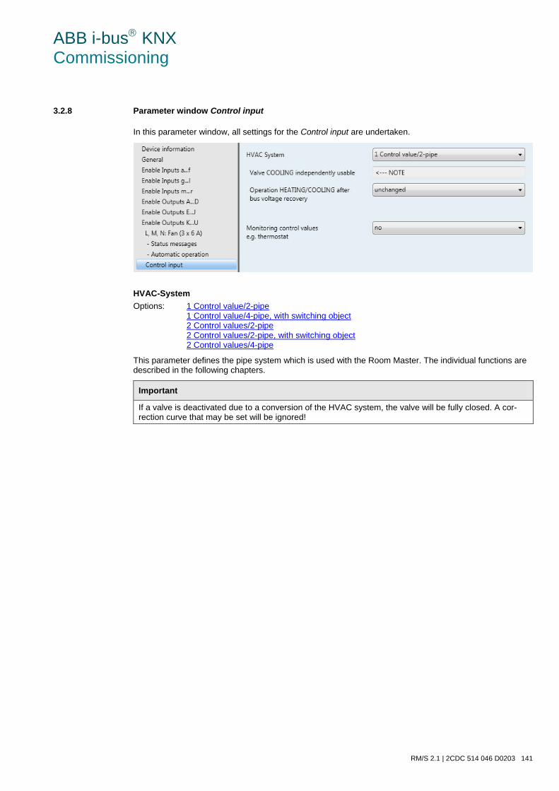
ABB i-bus KNX Commissioning
RM/S 2.1 | 2CDC 514 046 D0203 141
3.2.8 Parameter window Control input
In this parameter window, all settings for the Control input are undertaken.
HVAC-System Options: 1 Control value/2-pipe
1 Control value/4-pipe, with switching object 2 Control values/2-pipe 2 Control values/2-pipe, with switching object 2 Control values/4-pipe
This parameter defines the pipe system which is used with the Room Master. The individual functions are described in the following chapters.
Important
If a valve is deactivated due to a conversion of the HVAC system, the valve will be fully closed. A cor-rection curve that may be set will be ignored!
ABB i-bus KNX Commissioning
142 2CDC 514 046 D0203 | RM/S 2.1
Monitoring control values e.g. thermostat Options: no
yes
• yes: The communication object Fault control value is enabled. Hereby for example, a thermostat can be cyclically monitored. The following parameters appear:
Note
During a fault (emergency operation) when the control signal from the thermostat is no longer received, the Room Master autonomously performs a Pulse width modulation – Calculation, page 255, and (Pulse width modulation (PWM), page 253). For this purpose, the Room Master uses the programmable PWM cycle time.
Monitoring time in s [30…65,535] Options: 30…120…65,535
With this parameter, the time used to monitor all telegrams on the input/setting values of the RM/S is set: Communication objects Control value HEATING, Control value COOLING or Control value HEATING/COOLING.
If a setting variable is not received within the parameterized time, a communication malfunction has occurred and emergency operation is activated.
Important
It must be assured that the monitoring time is set to at least factor 3 larger than the set sending time of the thermostat.
The reaction of the RM/S to a setting value not received can be defined in the following parameters.
Send object value (Object "Control value fault" 1 bit) Options: no, update only
after a change after request after a change or request
• no, update only: The status is updated but not sent.
• after a change: The status is sent after a change.
• after request: The status is sent after a request.
• after a change or request: The status is sent after a change or a request.
Control value after control fault in % [0…100] Options: 0…30…100
This control value in percent can be set with a control value fault should the control fail (emergency operation).
ABB i-bus KNX Commissioning
RM/S 2.1 | 2CDC 514 046 D0203 143
3.2.8.1 HVAC system – 1 Control value/2 pipe
If option 1 Control value/2 pipe is selected, additional parameters appear:
Valve COOLING independently usable This parameter serves as a note or remark.
Valve COOLING The cooling valve can be used additionally and independently via the communication object Control value COOLING (extra!). The valve COOLING is not monitored in the process.
Valve HEATING Via communication object Control value HEATING/COOLING, the valve HEATING and the fan are controlled. For further information see: Configuration of a HVAC system with Fan Coil units, page 235.
Operation HEATING/COOLING after bus voltage recovery Options: unchanged
HEATING COOLING
Using this parameter, the reaction after bus voltage recovery is set.
• unchanged: After bus voltage recovery, the state which existed before bus voltage failure is set.
• HEATING: After bus voltage recovery, the HEATING state is set.
• COOLING: After bus voltage recovery, the COOLING state is set.
ABB i-bus KNX Commissioning
144 2CDC 514 046 D0203 | RM/S 2.1
3.2.8.2 HVAC-System – 1 Control value/4 pipe, with switching object
If option 1 Control values/4 pipe, with switching object is selected, additional parameters appear:
Toggle via separate object This parameter serves as a note or remark.
Valve HEATING/COOLING Using communication object Control value HEATING/COOLING, the valves HEATING/COOLING and the fans are controlled.
Toggle between HEATING and COOLING is implemented via the separate communication object Toggle HEATING/COOLING.
The corresponding inactive/non-actuated valve is thus automatically closed when toggled. For further information see: Configuration of a HVAC system with Fan Coil units, page 235.
Operation HEATING/COOLING after bus voltage recovery Options: unchanged
HEATING COOLING
Using this parameter, the reaction after bus voltage recovery is set.
• unchanged: After bus voltage recovery, the state which existed before bus voltage failure is set.
• HEATING: After bus voltage recovery, the HEATING state is set.
• COOLING: After bus voltage recovery, the COOLING state is set.
Object value for HEATING of the object “Toggle HEATING/COOLING” Options: 1
0
With this parameter, you set the communication object value used to toggle between HEATING and COOLING.
• 1: As soon as a telegram with the value 1 is received, HEATING is activated and COOLING is deac-tivated.
• 0: As soon as a telegram with the value 0 is received, HEATING is activated and COOLING is deac-tivated.
ABB i-bus KNX Commissioning
RM/S 2.1 | 2CDC 514 046 D0203 145
3.2.8.3 HVAC system – 2 Control values/2 pipe
If option 2 Control value/2 pipe is selected, additional parameters appear:
Toggle via automatically Valve COOLING not usable This parameter serves as a note or remark.
Valve HEATING/Valve COOLING Toggling between HEATING and COOLING is implemented by updating the control values. The HEATING/COOLING status is then set accordingly.
Note
The switch over between HEATING/COOLING should occur exclusively with the respective thermostat. Here only HEATING or COOLING are active, dependent on the last active control value received. • If a control with a value > 0 is received, the fan and the corresponding valve are controlled. • The other valve is closed. • If a control value with a value = 0 is received, this is ignored if the other control value > 0.
Caution With a 2 pipe HVAC system both the Control value HEATING as well as the Control value COOLING act on the HEATING valve (electronic outputs O, P). Please note that the last control value received always controls the HEATING valve. For 2 pipe systems, only the communication objects for the HEATING valve are relevant. The communication objects in conjunction with the COOLING valve, e.g. status, forced operation or valve purge are not effective.
For further information see: Configuration of a HVAC system with Fan Coil units, page 235.
Operation HEATING/COOLING after bus voltage recovery Options: unchanged
HEATING COOLING
Using this parameter, the reaction after bus voltage recovery is set.
• unchanged: After bus voltage recovery, the state which existed before bus voltage failure is set.
• HEATING: After bus voltage recovery, the HEATING state is set.
• COOLING: After bus voltage recovery, the COOLING state is set.
ABB i-bus KNX Commissioning
146 2CDC 514 046 D0203 | RM/S 2.1
3.2.8.4 HVAC-System – 2 Control values/2 pipe, with switching object
If option 2 Control values/2 pipe, with switching object is selected, additional parameters appear:
Toggle via separate object Valve COOLING cannot be used This parameter serves as a note or remark.
Valve HEATING/Valve COOLING The valve is controlled via the communication object Control value HEATING.
Toggle between HEATING and COOLING is implemented via the separate communication object Toggle HEATING/COOLING.
Caution With a 2 pipe HVAC system, both the Control value HEATING as well as the Control value COOLING act on the HEATING valve (electronic outputs O, P). Please note that always the last control value received and the switching object control the HEATING valve. For 2 pipe systems, only the communication objects for the HEATING valve are relevant. The communication objects in conjunction with the COOLING valve, e.g. status, forced operation or valve purge are not effective.
For further information see: Configuration of a HVAC system with Fan Coil units, page 235.
Operation HEATING/COOLING after bus voltage recovery Options: unchanged
HEATING COOLING
Using this parameter, the reaction after bus voltage recovery is set.
• unchanged: After bus voltage recovery, the state which existed before bus voltage failure is set.
• HEATING: After bus voltage recovery, the HEATING state is set.
• COOLING: After bus voltage recovery, the COOLING state is set.
Object value for HEATING of the object “Toggle HEATING/COOLING” Options: 1
0
With this parameter, you set the communication object value used to toggle between HEATING and COOLING.
• 1: As soon as a telegram with the value 1 is received, HEATING is activated and COOLING is deac-tivated.
• 0: As soon as a telegram with the value 0 is received, HEATING is activated and COOLING is deac-tivated.
ABB i-bus KNX Commissioning
RM/S 2.1 | 2CDC 514 046 D0203 147
3.2.8.5 HVAC system – 2 Control values/4 pipe
If option 2 Control values/4 pipe is selected, additional parameters appear:
Toggle via automatically This parameter serves as a note or remark.
Valve HEATING/Valve COOLING The HEATING valve is controlled via the communication object Control value HEATING.
The COOLING valve is controlled via the communication object Control value COOLING.
Toggling between HEATING and COOLING is implemented by updating the control values. The HEATING/COOLING status is then set accordingly.
Note
The switch over between HEATING/COOLING should occur exclusively with the respective thermostat. Here only HEATING or COOLING are active, dependent on the last active control value received. • If a control with a value > 0 is received, the fan and the corresponding valve are controlled. • The other valve is closed. • If a control value with a value = 0 is received, this is ignored if the other control value > 0.
For further information see: Configuration of a HVAC system with Fan Coil units, page 235.
Operation HEATING/COOLING after bus voltage recovery Options: unchanged
HEATING COOLING
Using this parameter, the reaction after bus voltage recovery is set.
• unchanged: After bus voltage recovery, the state which existed before bus voltage failure is set.
• HEATING: After bus voltage recovery, the HEATING state is set.
• COOLING: After bus voltage recovery, the COOLING state is set.
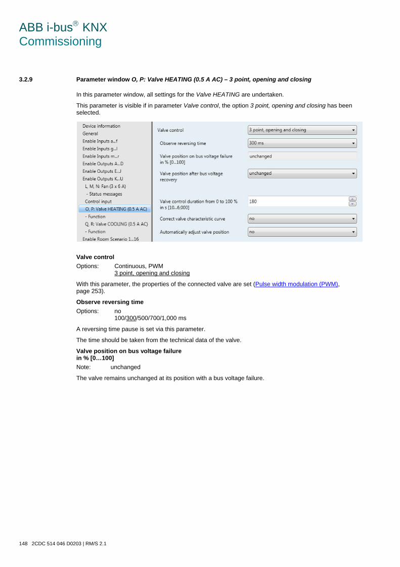
ABB i-bus KNX Commissioning
148 2CDC 514 046 D0203 | RM/S 2.1
3.2.9 Parameter window O, P: Valve HEATING (0.5 A AC) – 3 point, opening and closing
In this parameter window, all settings for the Valve HEATING are undertaken.
This parameter is visible if in parameter Valve control, the option 3 point, opening and closing has been selected.
Valve control Options: Continuous, PWM
3 point, opening and closing
With this parameter, the properties of the connected valve are set (Pulse width modulation (PWM), page 253).
Observe reversing time Options: no
100/300/500/700/1,000 ms
A reversing time pause is set via this parameter.
The time should be taken from the technical data of the valve.
Valve position on bus voltage failure in % [0…100] Note: unchanged
The valve remains unchanged at its position with a bus voltage failure.
ABB i-bus KNX Commissioning
RM/S 2.1 | 2CDC 514 046 D0203 149
Valve position after bus voltage recovery Option: unchanged
select
Using this parameter, the position of the valves after bus voltage recovery can be set.
• select: The following parameter appears:
Valve position in % [0…100] Option: 0…100
Using this parameter, the position of the valves after bus voltage recovery can be set as a percent-age.
Valve control duration from 0 to 100 % in s [10...6,000] Option: 10…180…6,000
With this parameter, a time is set in seconds that the connected valve requires to move from position 0 % (valve closed) to position 100 % (valve fully open).
Note
The time should be taken from the technical specification data of the valve.
Correct valve characteristic curve Option: no
yes
If the option yes is set, the Parameter window - Curve, page 158 appears, in which the valve curve is set.
Automatically adjust valve position Option: no
yes
• no: Nothing happens.
• yes: The following parameter appears.
Note
A manual triggering of the adjustment is not possible!
Adjust with control value 0 % Any action with control value 0 % is executed as an adjustment, i.e.:
• The valve is fully closed, regardless of the curve.
• The closing position is exceeded by 5 % of the total time, max. one minute.
• This function cannot be interrupted!
• Thereafter, the current valve position is approached, and the adjustment counter is set to zero.
ABB i-bus KNX Commissioning
150 2CDC 514 046 D0203 | RM/S 2.1
The following applies with automatic adjustment • The adjustment counter is incremented by 1 every time the valve stops.
• If the parameterized limit of the adjustment counter is exceeded in the closing direction, the adjustment starts.
• If higher priorities are activated at the time of automatic adjustment, the adjustment will be performed later.
• The adjustment is interrupted by higher priority events.
• The valve is fully closed, regardless of the curve.
• The closing position is exceeded by 5 % of the total time, max. one minute. This func-tion cannot be interrupted! Thereafter, the current valve position is approached, and the adjustment counter is set to zero.
Note
A valve adjustment has occurred if a control of the drive has actually been undertaken. If priorities and curves prevent this, the adjustment counter will not change.
Reference movement A referencing or homing run can be understood as a complete closing of the valve.
Referencing is undertaken after:
• Every reset of the bus.
• A change of version.
• Every reset of an un-parameterized device.
• A download with modified adjustment time.
The following should be considered:
• Referencing cannot be interrupted.
• The closing position is exceeded by 5 % of the total time, max. one minute.
• After the reference movement, the current valve position is moved to and the adjustment coun-ter is set to zero.
For further information see: Priorities with, …, page 261
Number of valve controls up to adjustment [1...65,535] Option: 1…100…65,535
With this parameter, the number of operations (valve controls), after which automatic adjustment is undertaken, can be set.
Note
All actions greater than zero (motor does not move) are counted. The number should be taken from the technical data of the valve manufacturer.
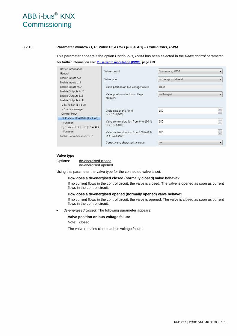
ABB i-bus KNX Commissioning
RM/S 2.1 | 2CDC 514 046 D0203 151
3.2.10 Parameter window O, P: Valve HEATING (0.5 A AC) – Continuous, PWM
This parameter appears if the option Continuous, PWM has been selected in the Valve control parameter. For further information see: Pulse width modulation (PWM), page 253
Valve type Options: de-energised closed
de-energised opened
Using this parameter the valve type for the connected valve is set.
How does a de-energised closed (normally closed) valve behave? If no current flows in the control circuit, the valve is closed. The valve is opened as soon as current flows in the control circuit.
How does a de-energised opened (normally opened) valve behave? If no current flows in the control circuit, the valve is opened. The valve is closed as soon as current flows in the control circuit.
• de-energised closed: The following parameter appears:
Valve position on bus voltage failure Note: closed
The valve remains closed at bus voltage failure.
ABB i-bus KNX Commissioning
152 2CDC 514 046 D0203 | RM/S 2.1
• de-energized opened: The following parameter appears:
Valve position on bus voltage failure Note: opened
The valve remains opened at bus voltage failure.
Valve position after bus voltage recovery Option: unchanged
select
Using this parameter, the position of the valves after bus voltage recovery can be set.
• select: The following parameter appears:
Valve position in % [0…100] Option: 0…100
Using this parameter, the position of the valves after bus voltage recovery can be set as a percent-age.
Cycle time of the PWM in s [10...6,000] Option: 10…180…6,000
This is used to set the cycle time of the PWM control.
Important
The minimum pulse length is defined as 0.5 seconds, so that with very short cycle times (< 1 min.), there are very short switch on times (with small percentage values) or switch off times (with higher per-centage values).
Valve control duration from 0 to 100 % in s [10...6,000] Option: 10…180…6,000
With this parameter, a time is set in seconds that the connected valve requires to move from position 0 % (valve closed) to position 100 % (valve fully open).
Note
The time should be taken from the technical data of the valve, and it corresponds with the total runtime.
Valve control duration from 100 to 0 % in s [10...6,000] Option: 10…180…6,000
With this parameter, a time is set in seconds that the connected valve requires to move from position 100 % (valve open) to position 0 % (valve fully closed).
Note
The time should be taken from the technical data of the valve, and it corresponds with the total runtime.
ABB i-bus KNX Commissioning
RM/S 2.1 | 2CDC 514 046 D0203 153
Fast heat up/cool down In addition to the adjustable time, an additional time is determined in dependence on the change in control value. Thus, faster heat up or cool down of a room is achieved. For determination of the ad-ditional time the difference between the current and the new control value is determined. The addi-tional time is dependent on how large the control value change from the current control value to the new control value should be.
Example
If the change in control value ascends, i.e. the current control value is at 10 % and the new con-trol value is at 20 %, fast heat up is activated. If the change in control value descends, i.e. the current control value is at 60 % and the new con-trol value is at 40 %, fast cool down is activated.
For further information see: Fast heat up/cool down, page 262.
Correct valve characteristic curve Option: no
yes
If the option yes is set in the parameter, the Parameter window - Curve, page 158 appears, in which the valve curve is set.
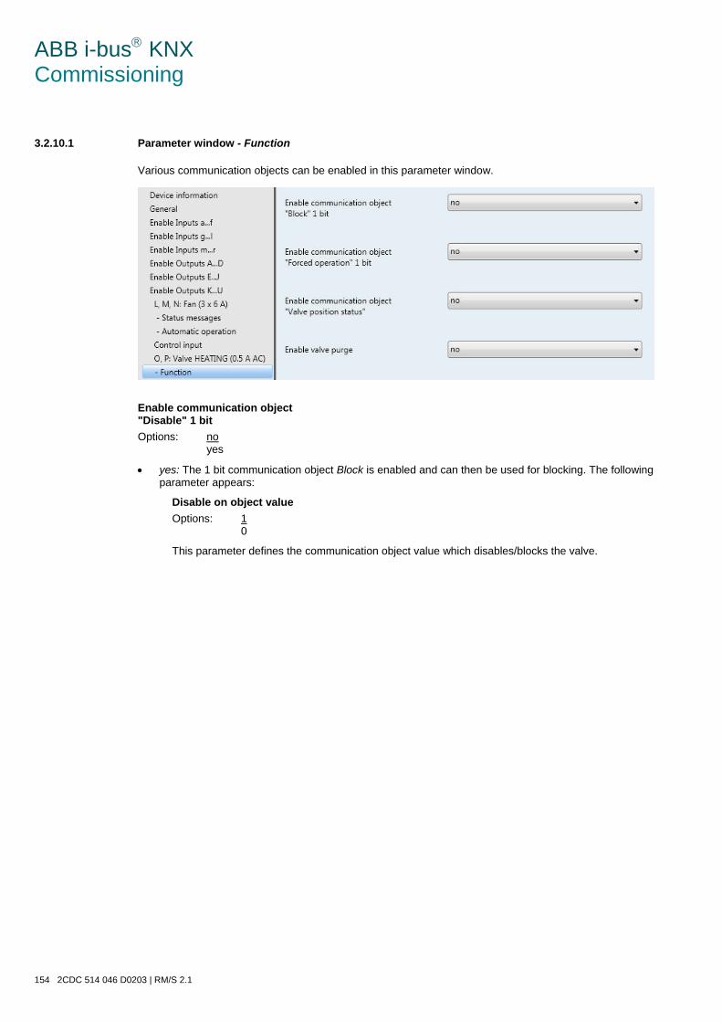
ABB i-bus KNX Commissioning
154 2CDC 514 046 D0203 | RM/S 2.1
3.2.10.1 Parameter window - Function
Various communication objects can be enabled in this parameter window.
Enable communication object "Disable" 1 bit Options: no
yes
• yes: The 1 bit communication object Block is enabled and can then be used for blocking. The following parameter appears:
Disable on object value Options: 1
0
This parameter defines the communication object value which disables/blocks the valve.
ABB i-bus KNX Commissioning
RM/S 2.1 | 2CDC 514 046 D0203 155
Enable communication object "Forced operation" 1 bit Options: no
yes
• yes: The 1 bit communication object Forced operation is enabled and can thus be forced operated. The following parameter appears:
Forced operation on object value Options: 1
0
This parameter defines the communication object value which forcibly operates the valve.
Valve position on forced operation in % [0…100] Options: 0…30…100
This parameter determines the valve position in percent during forced operation.
Enable communication object "Valve position status" Options: no
1 bit 1 byte
Note
The valve position status is sent immediately after the control value is received.
• 1 bit: The following parameters appear:
Send object value Options: no, update only
after a change after request after a change or request
• no, update only: The status is updated but not sent.
• after a change: The status is sent after a change.
• after request: The status is sent after a request.
• after a change or request: The status is sent after a change or a request.
Object value with valve position >0 Options: 1
0
ABB i-bus KNX Commissioning
156 2CDC 514 046 D0203 | RM/S 2.1
• 1 byte: The following parameter appears:
Send object value Options: no, update only
after a change after request after a change or request
• no, update only: The status is updated but not sent.
• after a change: The status is sent after a change.
• after request: The status is sent after a request.
• after a change or request: The status is sent after a change or a request.
Enable valve purge Options: no
yes
• yes: The 1 bit communication object Trigger valve purge is enabled.
Note
If the valve purge is interrupted by a higher priority, it will restart after the completion of the priority task, unless, for example, the control value was 100 % or it was active for the duration of the purge time due to the higher priority. The valve position for purging is always the control value 100 %. For further information see: Priorities with, …, page 261.
With option yes, the following parameters appear:
Enable communication object "Status valve purge" 1 bit Options: no
yes
• yes: The 1 bit communication object Status valve purge is enabled.
The status of the valve purge is visible via this communication object. The following parameter ap-pears:
Send object value Options: no, update only
after a change after request after a change or request
• no, update only: The status is updated but not sent.
• after a change: The status is sent after a change.
• after request: The status is sent after a request.
• after a change or request: The status is sent after a change or a request.
Note
The status is sent immediately as soon as a new control value is received.
ABB i-bus KNX Commissioning
RM/S 2.1 | 2CDC 514 046 D0203 157
Duration of valve purge in min. [1…255] Options: 1…10…255
This parameter defines the time duration for the valve purge. In this time, the valve is fully opened. When the time has elapsed, the state before the purge is re-established.
Note
The opening time of the valve must be considered when entering the purge time.
Automatic valve purge Options: no
yes
• yes: The following parameters appear:
Purge cycle in weeks [1…12] Options: 1…6…12
The counter for automatic purging starts to run when the parameter is downloaded. The time is re-set each time it is downloaded.
The time is reset as soon as purging is completed. This can occur either through automatic purging or via the communication object Trigger valve purge.
Note
Purging can also be triggered via the bus with the communication object Trigger valve purge. After bus voltage recovery and download the purge cycle continues, the bus failure time – the time for which the bus actually failed – is not considered. The purging cycle will restart if Purge cycle in weeks [1…12] is changed after the download.
Reset purge cycle from control value in % [1…99] Options: 1…99
Hereby, the purge cycle from the set control value is reset.
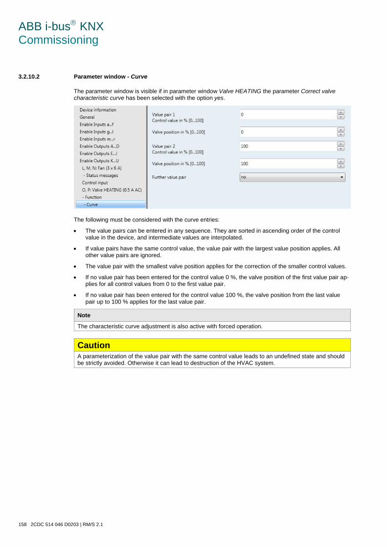
ABB i-bus KNX Commissioning
158 2CDC 514 046 D0203 | RM/S 2.1
3.2.10.2 Parameter window - Curve
The parameter window is visible if in parameter window Valve HEATING the parameter Correct valve characteristic curve has been selected with the option yes.
The following must be considered with the curve entries:
• The value pairs can be entered in any sequence. They are sorted in ascending order of the control value in the device, and intermediate values are interpolated.
• If value pairs have the same control value, the value pair with the largest value position applies. All other value pairs are ignored.
• The value pair with the smallest valve position applies for the correction of the smaller control values.
• If no value pair has been entered for the control value 0 %, the valve position of the first value pair ap-plies for all control values from 0 to the first value pair.
• If no value pair has been entered for the control value 100 %, the valve position from the last value pair up to 100 % applies for the last value pair.
Note
The characteristic curve adjustment is also active with forced operation.
Caution A parameterization of the value pair with the same control value leads to an undefined state and should be strictly avoided. Otherwise it can lead to destruction of the HVAC system.
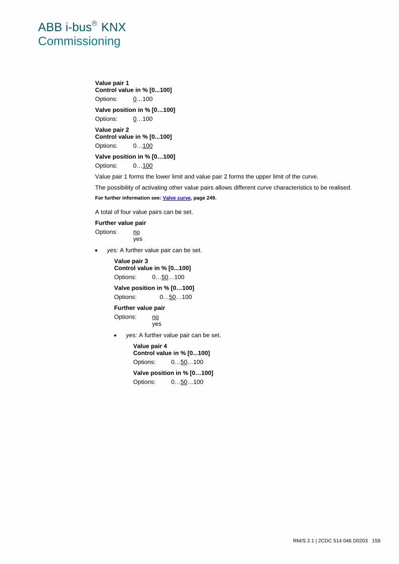
ABB i-bus KNX Commissioning
RM/S 2.1 | 2CDC 514 046 D0203 159
Value pair 1 Control value in % [0...100] Options: 0…100
Valve position in % [0…100] Options: 0…100
Value pair 2 Control value in % [0...100] Options: 0…100
Valve position in % [0…100] Options: 0…100
Value pair 1 forms the lower limit and value pair 2 forms the upper limit of the curve.
The possibility of activating other value pairs allows different curve characteristics to be realised. For further information see: Valve curve, page 249.
A total of four value pairs can be set.
Further value pair Options: no
yes
• yes: A further value pair can be set.
Value pair 3 Control value in % [0...100] Options: 0…50…100
Valve position in % [0…100] Options: 0…50…100
Further value pair Options: no
yes
• yes: A further value pair can be set.
Value pair 4 Control value in % [0...100] Options: 0…50…100
Valve position in % [0…100] Options: 0…50…100

ABB i-bus KNX Commissioning
160 2CDC 514 046 D0203 | RM/S 2.1
3.2.11 Parameter window Q, R: Valve COOLING (0.5 A AC)
The setting options of valve COOLING do not differentiate from those of valve HEATING.
The descriptions of the parameter setting options and adjustable communication objects for the valve COOLING are described under Parameter window O, P: Valve HEATING (0.5 A AC) – 3 point, opening and closing, page 147.
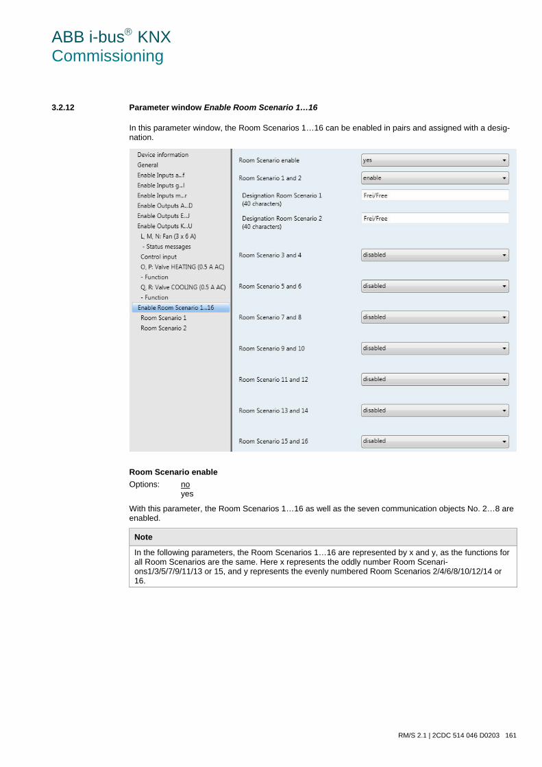
ABB i-bus KNX Commissioning
RM/S 2.1 | 2CDC 514 046 D0203 161
3.2.12 Parameter window Enable Room Scenario 1…16
In this parameter window, the Room Scenarios 1…16 can be enabled in pairs and assigned with a desig-nation.
Room Scenario enable Options: no
yes
With this parameter, the Room Scenarios 1…16 as well as the seven communication objects No. 2…8 are enabled.
Note
In the following parameters, the Room Scenarios 1…16 are represented by x and y, as the functions for all Room Scenarios are the same. Here x represents the oddly number Room Scenari-ons1/3/5/7/9/11/13 or 15, and y represents the evenly numbered Room Scenarios 2/4/6/8/10/12/14 or 16.
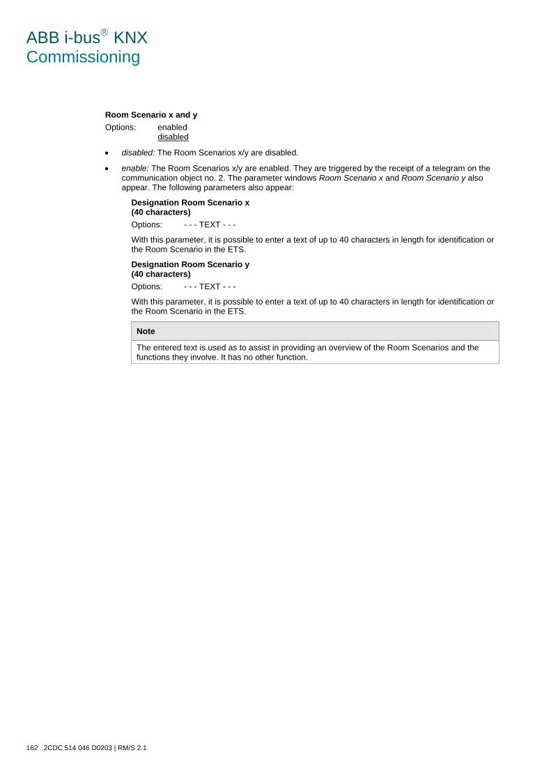
ABB i-bus KNX Commissioning
162 2CDC 514 046 D0203 | RM/S 2.1
Room Scenario x and y Options: enabled
disabled
• disabled: The Room Scenarios x/y are disabled.
• enable: The Room Scenarios x/y are enabled. They are triggered by the receipt of a telegram on the communication object no. 2. The parameter windows Room Scenario x and Room Scenario y also appear. The following parameters also appear:
Designation Room Scenario x (40 characters) Options: - - - TEXT - - -
With this parameter, it is possible to enter a text of up to 40 characters in length for identification or the Room Scenario in the ETS.
Designation Room Scenario y (40 characters) Options: - - - TEXT - - -
With this parameter, it is possible to enter a text of up to 40 characters in length for identification or the Room Scenario in the ETS.
Note
The entered text is used as to assist in providing an overview of the Room Scenarios and the functions they involve. It has no other function.
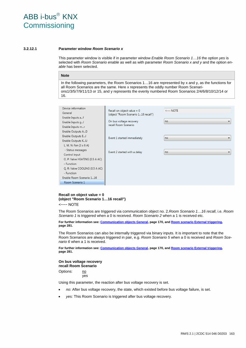
ABB i-bus KNX Commissioning
RM/S 2.1 | 2CDC 514 046 D0203 163
3.2.12.1 Parameter window Room Scenario x
This parameter window is visible if in parameter window Enable Room Scenario 1…16 the option yes is selected with Room Scenario enable as well as with parameter Room Scenario x and y and the option en-able has been selected.
Note
In the following parameters, the Room Scenarios 1…16 are represented by x and y, as the functions for all Room Scenarios are the same. Here x represents the oddly number Room Scenari-ons1/3/5/7/9/11/13 or 15, and y represents the evenly numbered Room Scenarios 2/4/6/8/10/12/14 or 16.
Recall on object value = 0 (object "Room Scenario 1…16 recall") <−−− NOTE
The Room Scenarios are triggered via communication object no. 2.Room Scenario 1…16 recall, i.e. Room Scenario 1 is triggered when a 0 is received. Room Scenario 2 when a 1 is received etc. For further information see: Communication objects General, page 170, and Room scenario External triggering, page 281. The Room Scenarios can also be internally triggered via binary inputs. It is important to note that the Room Scenarios are always triggered in pair, e.g. Room Scenario 5 when a 0 is received and Room Sce-nario 6 when a 1 is received. For further information see: Communication objects General, page 170, and Room scenario External triggering, page 281.
On bus voltage recovery recall Room Scenario Options: no
yes
Using this parameter, the reaction after bus voltage recovery is set.
• no: After bus voltage recovery, the state, which existed before bus voltage failure, is set.
• yes: This Room Scenario is triggered after bus voltage recovery.
ABB i-bus KNX Commissioning
164 2CDC 514 046 D0203 | RM/S 2.1
Event 1 started immediately Options: no
yes
• no: This is no reaction, when the value 0 is received. Event 1 is not started.
• yes: If the value 0 is received, event 1 starts. Event 1 is set via the following parameters.
Scene recall Options: only device internal
only via the bus: device internal and via the bus:
This parameter defines how and where a scene recall is sent with the start of event 1 via communi-cation object no. 6 Room Scenario Scene recall.
• only device internal: The set scene number is only recalled internally in the device, e.g. in order to trigger a determined room state.
• only via the bus: The set scene number is only sent via the bus. Accordingly, further KNX de-vices can be integrated into the Room Scenario, or these are also contacted by a scene recall.
• device internal and via the bus: The set scene number is recalled both device internally as well as being sent via the bus. Thus, a Room Scenario can be triggered, and further KNX devices integrated into the scene can be contacted.
Scene number [1…64] Options: 1…64
This parameter defines the scene number, which is to be triggered by a scene recall. 64 scene numbers are available.
Switch 1 send Options: no
ON OFF TOGGLE
This parameter defines if and with which value the communication object no. 3 should send a tele-gram.
• no: There is no reaction with the start of the event.
• ON: A telegram with the value 1 is sent via the communication object no. 3.
• OFF: A telegram with the value 0 is sent via the communication object no. 3.
• TOGGLE: Via the communication object no. 3, a telegram is sent with the opposite value, e.g. if the value 1 was read beforehand, when the event 1 is recalled the value 0 is sent, and vice versa.
ABB i-bus KNX Commissioning
RM/S 2.1 | 2CDC 514 046 D0203 165
Switch 2 send Options: no
ON OFF TOGGLE
This parameter defines if and with which value the communication object no. 4 should send a tele-gram.
• no: There is no reaction with the start of the event.
• ON: A telegram with the value 1 is sent via the communication object no. 4.
• OFF: A telegram with the value 0 is sent via the communication object no. 4.
• TOGGLE: Via the communication object no. 4, a telegram is sent with the opposite value, e.g. if the value 1 was read beforehand, when the event 1 is recalled the value 0 is sent, and vice versa.
ON/OFF send to thermostat Options: no
ON OFF
This parameter defines whether a thermostat, e.g. RDF/A is switched on or off, or whether it re-mains in an unchanged state.
• no: There is no reaction with the start of the event.
• ON: A telegram with the value 1 is sent via the communication object no. 8.
• OFF: A telegram with the value 0 is sent via the communication object no. 8.
1 byte value send Options: no
value [0…255]
This parameter determines whether a 1 byte value is sent.
• value [0…255]: The following parameter appears:
ABB i-bus KNX Commissioning
166 2CDC 514 046 D0203 | RM/S 2.1
send value Options: 0…255
Via communication object no. 9, a telegram with the respective value is sent on the bus.
Automatic Blind output enable Options: no
yes
• no: There is no reaction with the start of the event.
• yes: The automatic function of output K is activated internally via the communication object no. 5 Automatic Blind recall (1 bit). At the same time, the telegram for automatic activation is sent on the bus. The KNX devices integrated into the automatic function are also contacted.
Note
The internal activation of the automatic function only occurs if in parameter window Output K: Blinds/Shutters is enabled with the Enable function automatic.
Internal blocking the inputs Options: unchanged
activate deactivate
This parameter acts directly on the binary inputs, which allow an internal block.
• unchanged: The internal block remains unchanged.
• active: The internal block is activated.
• deactivate: The internal block is deactivated. For further information see: Block binary inputs, page 268
Event 2 started with a delay Options: no
yes
• no: This is no reaction, when the value 0 is received. Event 2 is not started.
• yes: If the value 0 is received, event 2 starts. Event 2 is set via the following parameters.
Delay time in s [0…65,535] Options: 0…30…65,535
This parameter determines the duration, after which event 2 is started.
Note
The following parameters and their descriptions do not differ from those with the description Event 1 started immediately, page 164.

ABB i-bus KNX Commissioning
RM/S 2.1 | 2CDC 514 046 D0203 167
3.2.13 Commissioning without bus voltage
How is the device switched on and put into operation? The device can be made operational by applying an auxiliary voltage from the power supply (NTI).
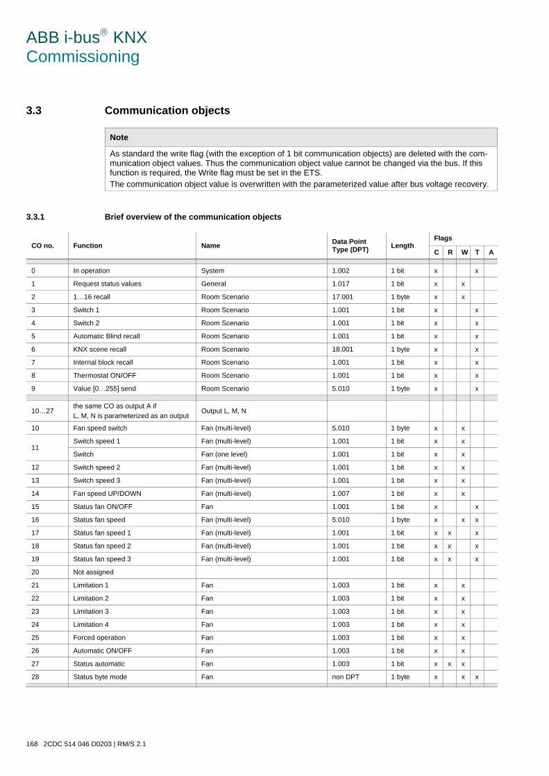
ABB i-bus KNX Commissioning
168 2CDC 514 046 D0203 | RM/S 2.1
3.3 Communication objects
Note
As standard the write flag (with the exception of 1 bit communication objects) are deleted with the com-munication object values. Thus the communication object value cannot be changed via the bus. If this function is required, the Write flag must be set in the ETS. The communication object value is overwritten with the parameterized value after bus voltage recovery.
3.3.1 Brief overview of the communication objects
CO no. Function Name Data Point Type (DPT) Length
Flags
C R W T A
0 In operation System 1.002 1 bit x x
1 Request status values General 1.017 1 bit x x
2 1…16 recall Room Scenario 17.001 1 byte x x
3 Switch 1 Room Scenario 1.001 1 bit x x
4 Switch 2 Room Scenario 1.001 1 bit x x
5 Automatic Blind recall Room Scenario 1.001 1 bit x x
6 KNX scene recall Room Scenario 18.001 1 byte x x
7 Internal block recall Room Scenario 1.001 1 bit x x
8 Thermostat ON/OFF Room Scenario 1.001 1 bit x x
9 Value [0…255] send Room Scenario 5.010 1 byte x x
10…27
the same CO as output A if L, M, N is parameterized as an output
Output L, M, N
10 Fan speed switch Fan (multi-level) 5.010 1 byte x x
11 Switch speed 1 Fan (multi-level) 1.001 1 bit x x
Switch Fan (one level) 1.001 1 bit x x
12 Switch speed 2 Fan (multi-level) 1.001 1 bit x x
13 Switch speed 3 Fan (multi-level) 1.001 1 bit x x
14 Fan speed UP/DOWN Fan (multi-level) 1.007 1 bit x x
15 Status fan ON/OFF Fan 1.001 1 bit x x
16 Status fan speed Fan (multi-level) 5.010 1 byte x x x
17 Status fan speed 1 Fan (multi-level) 1.001 1 bit x x x
18 Status fan speed 2 Fan (multi-level) 1.001 1 bit x x x
19 Status fan speed 3 Fan (multi-level) 1.001 1 bit x x x
20 Not assigned
21 Limitation 1 Fan 1.003 1 bit x x
22 Limitation 2 Fan 1.003 1 bit x x
23 Limitation 3 Fan 1.003 1 bit x x
24 Limitation 4 Fan 1.003 1 bit x x
25 Forced operation Fan 1.003 1 bit x x
26 Automatic ON/OFF Fan 1.003 1 bit x x
27 Status automatic Fan 1.003 1 bit x x x
28 Status byte mode Fan non DPT 1 byte x x x
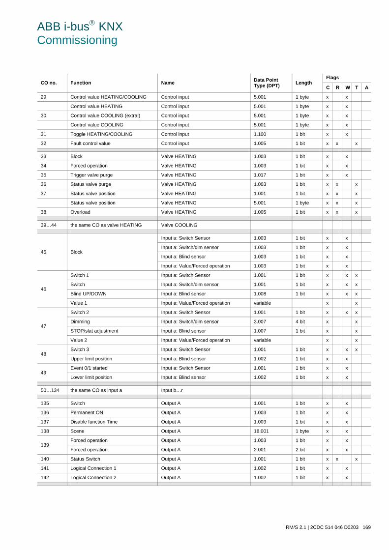
ABB i-bus KNX Commissioning
RM/S 2.1 | 2CDC 514 046 D0203 169
CO no. Function Name Data Point Type (DPT) Length
Flags
C R W T A
29 Control value HEATING/COOLING Control input 5.001 1 byte x x
Control value HEATING Control input 5.001 1 byte x x
30 Control value COOLING (extra!) Control input 5.001 1 byte x x
Control value COOLING Control input 5.001 1 byte x x
31 Toggle HEATING/COOLING Control input 1.100 1 bit x x
32 Fault control value Control input 1.005 1 bit x x x
33 Block Valve HEATING 1.003 1 bit x x
34 Forced operation Valve HEATING 1.003 1 bit x x
35 Trigger valve purge Valve HEATING 1.017 1 bit x x
36 Status valve purge Valve HEATING 1.003 1 bit x x x
37 Status valve position Valve HEATING 1.001 1 bit x x x
Status valve position Valve HEATING 5.001 1 byte x x x
38 Overload Valve HEATING 1.005 1 bit x x x
39…44 the same CO as valve HEATING Valve COOLING
45 Block
Input a: Switch Sensor 1.003 1 bit x x
Input a: Switch/dim sensor 1.003 1 bit x x
Input a: Blind sensor 1.003 1 bit x x
Input a: Value/Forced operation 1.003 1 bit x x
46
Switch 1 Input a: Switch Sensor 1.001 1 bit x x x
Switch Input a: Switch/dim sensor 1.001 1 bit x x x
Blind UP/DOWN Input a: Blind sensor 1.008 1 bit x x x
Value 1 Input a: Value/Forced operation variable x x
47
Switch 2 Input a: Switch Sensor 1.001 1 bit x x x
Dimming Input a: Switch/dim sensor 3.007 4 bit x x
STOP/slat adjustment Input a: Blind sensor 1.007 1 bit x x
Value 2 Input a: Value/Forced operation variable x x
48 Switch 3 Input a: Switch Sensor 1.001 1 bit x x x
Upper limit position Input a: Blind sensor 1.002 1 bit x x
49 Event 0/1 started Input a: Switch Sensor 1.001 1 bit x x
Lower limit position Input a: Blind sensor 1.002 1 bit x x
50…134 the same CO as input a Input b…r
135 Switch Output A 1.001 1 bit x x
136 Permanent ON Output A 1.003 1 bit x x
137 Disable function Time Output A 1.003 1 bit x x
138 Scene Output A 18.001 1 byte x x
139 Forced operation Output A 1.003 1 bit x x
Forced operation Output A 2.001 2 bit x x
140 Status Switch Output A 1.001 1 bit x x x
141 Logical Connection 1 Output A 1.002 1 bit x x
142 Logical Connection 2 Output A 1.002 1 bit x x
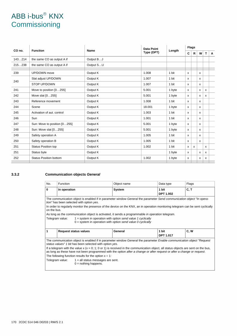
ABB i-bus KNX Commissioning
170 2CDC 514 046 D0203 | RM/S 2.1
CO no. Function Name Data Point Type (DPT) Length
Flags
C R W T A
143…214 the same CO as output A if Output B…J
215…238 the same CO as output A if Output S…U
239 UP/DOWN move Output K 1.008 1 bit x x
240 Slat adjust UP/DOWN Output K 1.007 1 bit x x
STOP UP/DOWN Output K 1.007 1 bit x x
241 Move to position [0…255] Output K 5.001 1 byte x x x
242 Move slat [0…255] Output K 5.001 1 byte x x x
243 Reference movement Output K 1.008 1 bit x x
244 Scene Output K 18.001 1 byte x x
245 Activation of aut. control Output K 1.003 1 bit x x
246 Sun Output K 1.001 1 bit x x
247 Sun: Move to position [0…255] Output K 5.001 1 byte x x
248 Sun: Move slat [0…255] Output K 5.001 1 byte x x
249 Safety operation A Output K 1.005 1 bit x x
250 Safety operation B Output K 1.005 1 bit x x
251 Status Position top Output K 1.002 1 bit x x x
251 Status byte Output K 1 byte x x x
252 Status Position bottom Output K 1.002 1 byte x x x
3.3.2 Communication objects General
No. Function Object name Data type Flags
0 In operation System 1 bit DPT 1.002
C, T
The communication object is enabled if in parameter window General the parameter Send communication object "In opera-tion" has been selected with option yes. In order to regularly monitor the presence of the device on the KNX, an in operation monitoring telegram can be sent cyclically on the bus. As long as the communication object is activated, it sends a programmable in operation telegram. Telegram value: 1 = system in operation with option send value 1 cyclically
0 = system in operation with option send value 0 cyclically
1 Request status values General 1 bit DPT 1.017
C, W
The communication object is enabled if in parameter window General the parameter Enable communication object "Request status values" 1 bit has been selected with option yes. If a telegram with the value x (x = 0; 1; 0 or 1) is received in the communication object, all status objects are sent on the bus, as long as these have not been programmed with the option after a change or after request or after a change or request. The following function results for the option x = 1: Telegram value: 1 = all status messages are sent.
0 = nothing happens.
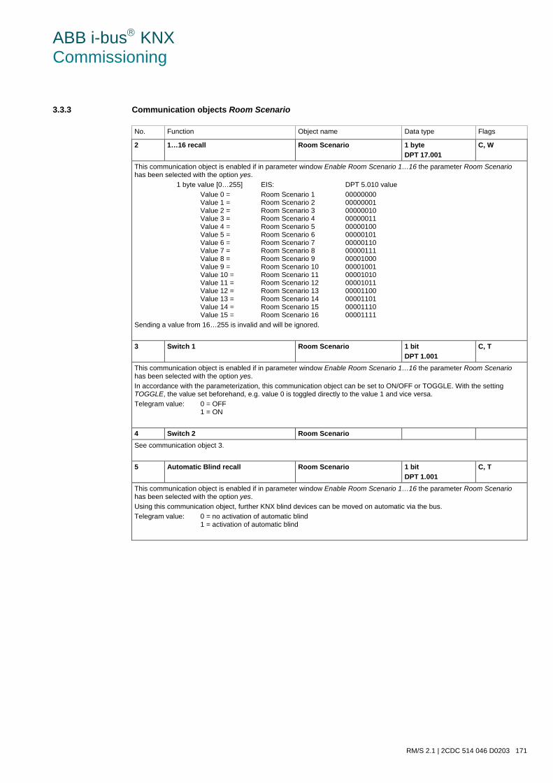
ABB i-bus KNX Commissioning
RM/S 2.1 | 2CDC 514 046 D0203 171
3.3.3 Communication objects Room Scenario
No. Function Object name Data type Flags
2 1…16 recall Room Scenario 1 byte DPT 17.001
C, W
This communication object is enabled if in parameter window Enable Room Scenario 1…16 the parameter Room Scenario has been selected with the option yes. 1 byte value [0…255] EIS: DPT 5.010 value
Value 0 = Room Scenario 1 00000000 Value 1 = Room Scenario 2 00000001 Value 2 = Room Scenario 3 00000010 Value 3 = Room Scenario 4 00000011 Value 4 = Room Scenario 5 00000100 Value 5 = Room Scenario 6 00000101 Value 6 = Room Scenario 7 00000110 Value 7 = Room Scenario 8 00000111 Value 8 = Room Scenario 9 00001000 Value 9 = Room Scenario 10 00001001 Value 10 = Room Scenario 11 00001010 Value 11 = Room Scenario 12 00001011 Value 12 = Room Scenario 13 00001100 Value 13 = Room Scenario 14 00001101 Value 14 = Room Scenario 15 00001110 Value 15 = Room Scenario 16 00001111
Sending a value from 16…255 is invalid and will be ignored.
3 Switch 1 Room Scenario 1 bit DPT 1.001
C, T
This communication object is enabled if in parameter window Enable Room Scenario 1…16 the parameter Room Scenario has been selected with the option yes. In accordance with the parameterization, this communication object can be set to ON/OFF or TOGGLE. With the setting TOGGLE, the value set beforehand, e.g. value 0 is toggled directly to the value 1 and vice versa. Telegram value: 0 = OFF
1 = ON
4 Switch 2 Room Scenario See communication object 3.
5 Automatic Blind recall Room Scenario 1 bit DPT 1.001
C, T
This communication object is enabled if in parameter window Enable Room Scenario 1…16 the parameter Room Scenario has been selected with the option yes. Using this communication object, further KNX blind devices can be moved on automatic via the bus. Telegram value: 0 = no activation of automatic blind
1 = activation of automatic blind
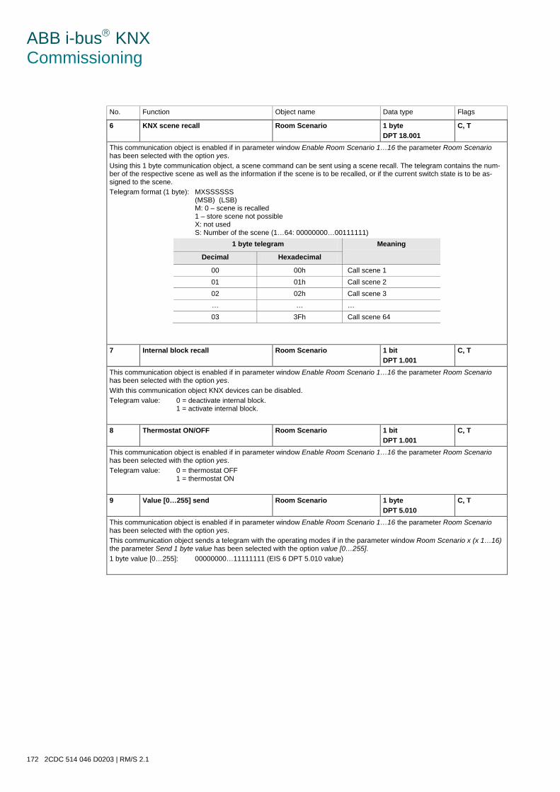
ABB i-bus KNX Commissioning
172 2CDC 514 046 D0203 | RM/S 2.1
No. Function Object name Data type Flags
6 KNX scene recall Room Scenario 1 byte DPT 18.001
C, T
This communication object is enabled if in parameter window Enable Room Scenario 1…16 the parameter Room Scenario has been selected with the option yes. Using this 1 byte communication object, a scene command can be sent using a scene recall. The telegram contains the num-ber of the respective scene as well as the information if the scene is to be recalled, or if the current switch state is to be as-signed to the scene. Telegram format (1 byte): MXSSSSSS
(MSB) (LSB) M: 0 – scene is recalled 1 – store scene not possible X: not used S: Number of the scene (1…64: 00000000…00111111)
1 byte telegram Meaning
Decimal Hexadecimal
00 00h Call scene 1 01 01h Call scene 2 02 02h Call scene 3 … … … 03 3Fh Call scene 64
7 Internal block recall Room Scenario 1 bit DPT 1.001
C, T
This communication object is enabled if in parameter window Enable Room Scenario 1…16 the parameter Room Scenario has been selected with the option yes. With this communication object KNX devices can be disabled. Telegram value: 0 = deactivate internal block.
1 = activate internal block.
8 Thermostat ON/OFF Room Scenario 1 bit DPT 1.001
C, T
This communication object is enabled if in parameter window Enable Room Scenario 1…16 the parameter Room Scenario has been selected with the option yes. Telegram value: 0 = thermostat OFF
1 = thermostat ON
9 Value [0…255] send Room Scenario 1 byte DPT 5.010
C, T
This communication object is enabled if in parameter window Enable Room Scenario 1…16 the parameter Room Scenario has been selected with the option yes. This communication object sends a telegram with the operating modes if in the parameter window Room Scenario x (x 1…16) the parameter Send 1 byte value has been selected with the option value [0…255]. 1 byte value [0…255]: 00000000…11111111 (EIS 6 DPT 5.010 value)
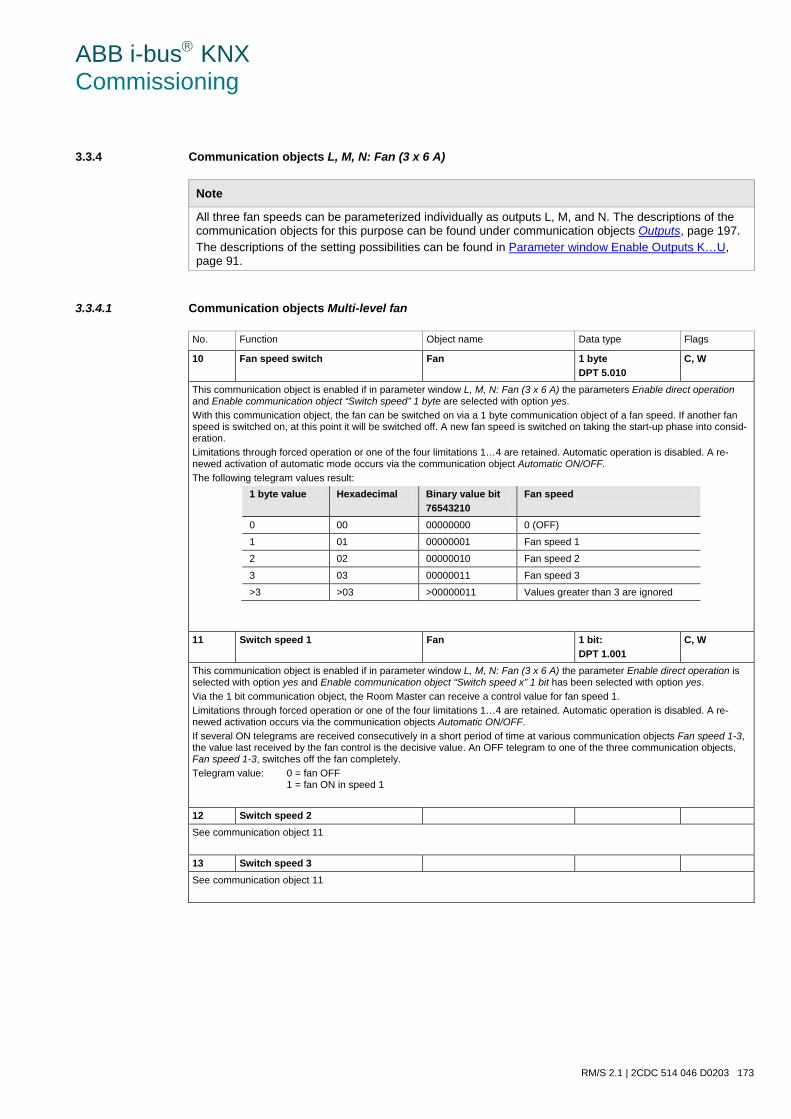
ABB i-bus KNX Commissioning
RM/S 2.1 | 2CDC 514 046 D0203 173
3.3.4 Communication objects L, M, N: Fan (3 x 6 A)
Note
All three fan speeds can be parameterized individually as outputs L, M, and N. The descriptions of the communication objects for this purpose can be found under communication objects Outputs, page 197. The descriptions of the setting possibilities can be found in Parameter window Enable Outputs K…U, page 91.
3.3.4.1 Communication objects Multi-level fan
No. Function Object name Data type Flags
10 Fan speed switch Fan 1 byte DPT 5.010
C, W
This communication object is enabled if in parameter window L, M, N: Fan (3 x 6 A) the parameters Enable direct operation and Enable communication object “Switch speed” 1 byte are selected with option yes. With this communication object, the fan can be switched on via a 1 byte communication object of a fan speed. If another fan speed is switched on, at this point it will be switched off. A new fan speed is switched on taking the start-up phase into consid-eration. Limitations through forced operation or one of the four limitations 1…4 are retained. Automatic operation is disabled. A re-newed activation of automatic mode occurs via the communication object Automatic ON/OFF. The following telegram values result:
1 byte value Hexadecimal Binary value bit 76543210
Fan speed
0 00 00000000 0 (OFF)
1 01 00000001 Fan speed 1
2 02 00000010 Fan speed 2
3 03 00000011 Fan speed 3
>3 >03 >00000011 Values greater than 3 are ignored
11 Switch speed 1 Fan 1 bit: DPT 1.001
C, W
This communication object is enabled if in parameter window L, M, N: Fan (3 x 6 A) the parameter Enable direct operation is selected with option yes and Enable communication object “Switch speed x” 1 bit has been selected with option yes. Via the 1 bit communication object, the Room Master can receive a control value for fan speed 1. Limitations through forced operation or one of the four limitations 1…4 are retained. Automatic operation is disabled. A re-newed activation occurs via the communication objects Automatic ON/OFF. If several ON telegrams are received consecutively in a short period of time at various communication objects Fan speed 1-3, the value last received by the fan control is the decisive value. An OFF telegram to one of the three communication objects, Fan speed 1-3, switches off the fan completely. Telegram value: 0 = fan OFF
1 = fan ON in speed 1
12 Switch speed 2 See communication object 11
13 Switch speed 3 See communication object 11
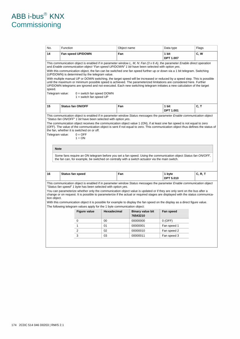
ABB i-bus KNX Commissioning
174 2CDC 514 046 D0203 | RM/S 2.1
No. Function Object name Data type Flags
14 Fan speed UP/DOWN Fan 1 bit DPT 1.007
C, W
This communication object is enabled if in parameter window L, M, N: Fan (3 x 6 A), the parameter Enable direct operation and Enable communication object “Fan speed UP/DOWN” 1 bit have been selected with option yes. With this communication object, the fan can be switched one fan speed further up or down via a 1 bit telegram. Switching (UP/DOWN) is determined by the telegram value. With multiple manual UP or DOWN switching, the target speed will be increased or reduced by a speed step. This is possible until the maximum or minimum possible speed is achieved. The parameterized limitations are considered here. Further UP/DOWN telegrams are ignored and not executed. Each new switching telegram initiates a new calculation of the target speed. Telegram value: 0 = switch fan speed DOWN
1 = switch fan speed UP
15 Status fan ON/OFF Fan 1 bit DPT 1.001
C, T
This communication object is enabled if in parameter window Status messages the parameter Enable communication object "Status fan ON/OFF" 1 bit have been selected with option yes. The communication object receives the communication object value 1 (ON), if at least one fan speed is not equal to zero (OFF). The value of the communication object is sent if not equal to zero. This communication object thus defines the status of the fan, whether it is switched on or off. Telegram value: 0 = OFF
1 = ON
Note
Some fans require an ON telegram before you set a fan speed. Using the communication object Status fan ON/OFF, the fan can, for example, be switched on centrally with a switch actuator via the main switch.
16 Status fan speed Fan 1 byte DPT 5.010
C, R, T
This communication object is enabled if in parameter window Status messages the parameter Enable communication object "Status fan speed" 1 byte has been selected with option yes. You can parameterize whether only the communication object value is updated or if they are only sent on the bus after a change or on request. It is possible to parameterize if the actual or required stages are displayed with the status communica-tion object. With this communication object it is possible for example to display the fan speed on the display as a direct figure value. The following telegram values apply for the 1 byte communication object:
Figure value Hexadecimal Binary value bit 76543210
Fan speed
0 00 00000000 0 (OFF) 1 01 00000001 Fan speed 1 2 02 00000010 Fan speed 2 3 03 00000011 Fan speed 3
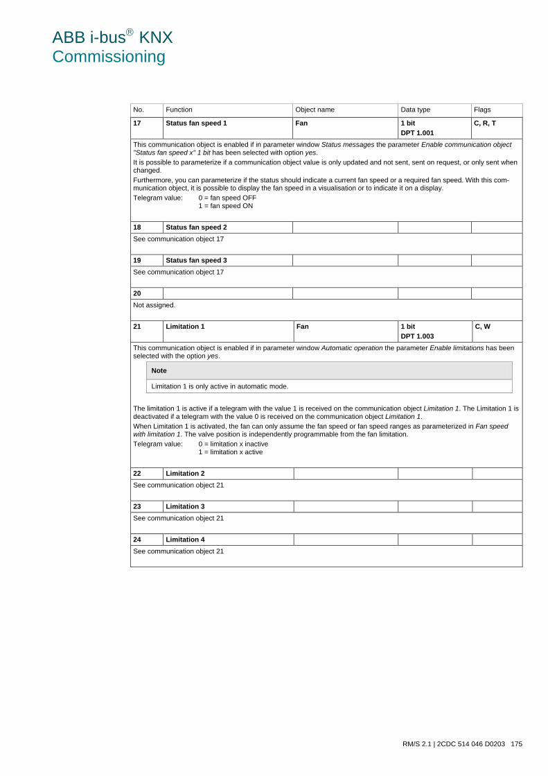
ABB i-bus KNX Commissioning
RM/S 2.1 | 2CDC 514 046 D0203 175
No. Function Object name Data type Flags
17 Status fan speed 1 Fan 1 bit DPT 1.001
C, R, T
This communication object is enabled if in parameter window Status messages the parameter Enable communication object "Status fan speed x" 1 bit has been selected with option yes. It is possible to parameterize if a communication object value is only updated and not sent, sent on request, or only sent when changed. Furthermore, you can parameterize if the status should indicate a current fan speed or a required fan speed. With this com-munication object, it is possible to display the fan speed in a visualisation or to indicate it on a display. Telegram value: 0 = fan speed OFF
1 = fan speed ON
18 Status fan speed 2 See communication object 17
19 Status fan speed 3 See communication object 17
20 Not assigned.
21 Limitation 1 Fan 1 bit DPT 1.003
C, W
This communication object is enabled if in parameter window Automatic operation the parameter Enable limitations has been selected with the option yes.
Note
Limitation 1 is only active in automatic mode.
The limitation 1 is active if a telegram with the value 1 is received on the communication object Limitation 1. The Limitation 1 is deactivated if a telegram with the value 0 is received on the communication object Limitation 1. When Limitation 1 is activated, the fan can only assume the fan speed or fan speed ranges as parameterized in Fan speed with limitation 1. The valve position is independently programmable from the fan limitation. Telegram value: 0 = limitation x inactive
1 = limitation x active
22 Limitation 2 See communication object 21
23 Limitation 3 See communication object 21
24 Limitation 4 See communication object 21
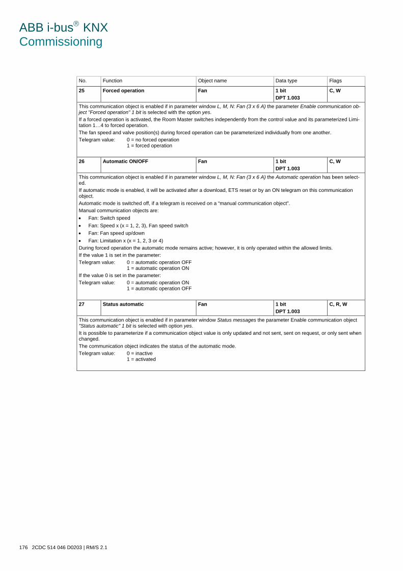
ABB i-bus KNX Commissioning
176 2CDC 514 046 D0203 | RM/S 2.1
No. Function Object name Data type Flags
25 Forced operation Fan 1 bit DPT 1.003
C, W
This communication object is enabled if in parameter window L, M, N: Fan (3 x 6 A) the parameter Enable communication ob-ject "Forced operation" 1 bit is selected with the option yes. If a forced operation is activated, the Room Master switches independently from the control value and its parameterized Limi-tation 1…4 to forced operation. The fan speed and valve position(s) during forced operation can be parameterized individually from one another. Telegram value: 0 = no forced operation
1 = forced operation
26 Automatic ON/OFF Fan 1 bit DPT 1.003
C, W
This communication object is enabled if in parameter window L, M, N: Fan (3 x 6 A) the Automatic operation has been select-ed. If automatic mode is enabled, it will be activated after a download, ETS reset or by an ON telegram on this communication object. Automatic mode is switched off, if a telegram is received on a “manual communication object”. Manual communication objects are: • Fan: Switch speed • Fan: Speed x (x = 1, 2, 3), Fan speed switch • Fan: Fan speed up/down • Fan: Limitation x (x = 1, 2, 3 or 4) During forced operation the automatic mode remains active; however, it is only operated within the allowed limits. If the value 1 is set in the parameter: Telegram value: 0 = automatic operation OFF
1 = automatic operation ON If the value 0 is set in the parameter: Telegram value: 0 = automatic operation ON
1 = automatic operation OFF
27 Status automatic Fan 1 bit DPT 1.003
C, R, W
This communication object is enabled if in parameter window Status messages the parameter Enable communication object "Status automatic" 1 bit is selected with option yes. It is possible to parameterize if a communication object value is only updated and not sent, sent on request, or only sent when changed. The communication object indicates the status of the automatic mode. Telegram value: 0 = inactive
1 = activated
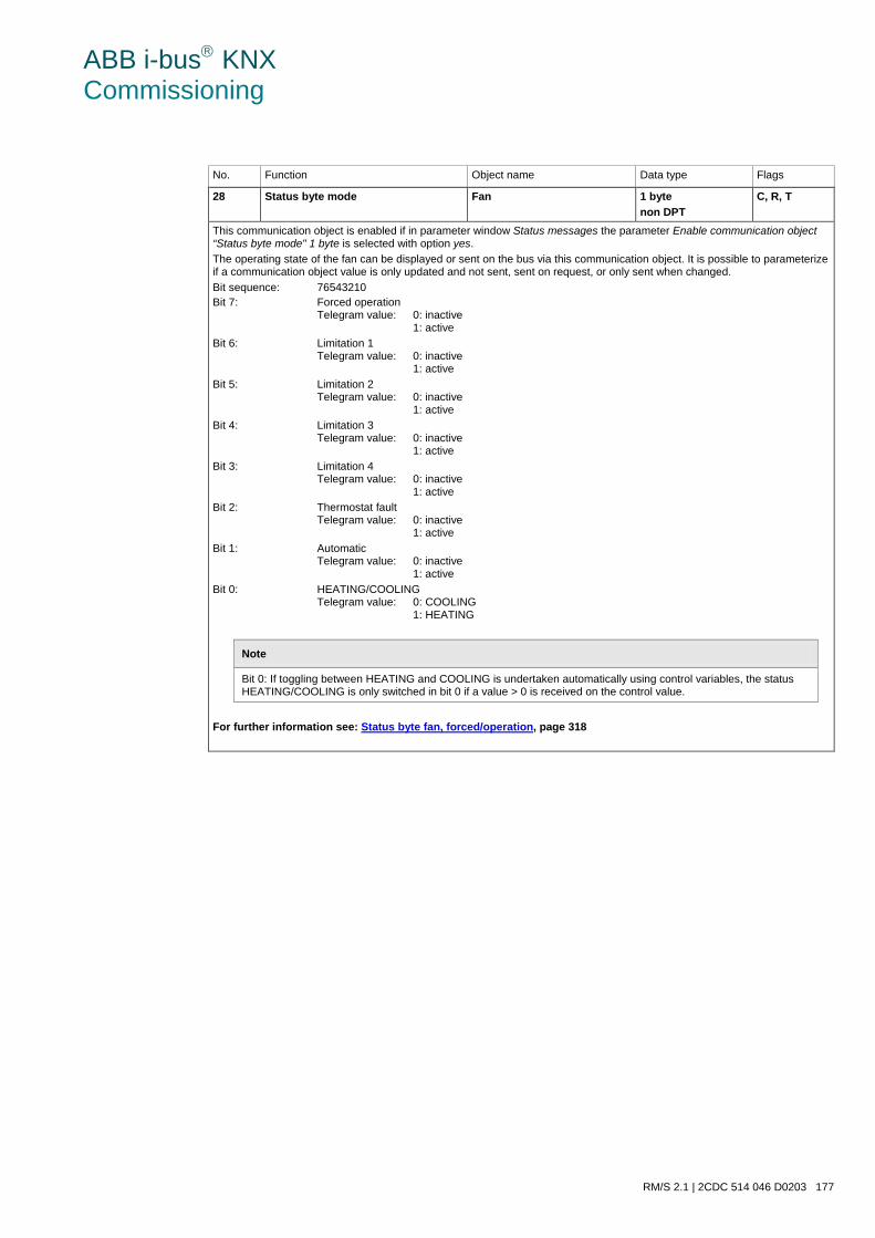
ABB i-bus KNX Commissioning
RM/S 2.1 | 2CDC 514 046 D0203 177
No. Function Object name Data type Flags
28 Status byte mode Fan 1 byte non DPT
C, R, T
This communication object is enabled if in parameter window Status messages the parameter Enable communication object “Status byte mode" 1 byte is selected with option yes. The operating state of the fan can be displayed or sent on the bus via this communication object. It is possible to parameterize if a communication object value is only updated and not sent, sent on request, or only sent when changed. Bit sequence: 76543210 Bit 7: Forced operation
Telegram value: 0: inactive 1: active
Bit 6: Limitation 1 Telegram value: 0: inactive 1: active
Bit 5: Limitation 2 Telegram value: 0: inactive 1: active
Bit 4: Limitation 3 Telegram value: 0: inactive 1: active
Bit 3: Limitation 4 Telegram value: 0: inactive 1: active
Bit 2: Thermostat fault Telegram value: 0: inactive 1: active
Bit 1: Automatic Telegram value: 0: inactive 1: active
Bit 0: HEATING/COOLING Telegram value: 0: COOLING 1: HEATING
Note
Bit 0: If toggling between HEATING and COOLING is undertaken automatically using control variables, the status HEATING/COOLING is only switched in bit 0 if a value > 0 is received on the control value.
For further information see: Status byte fan, forced/operation, page 318
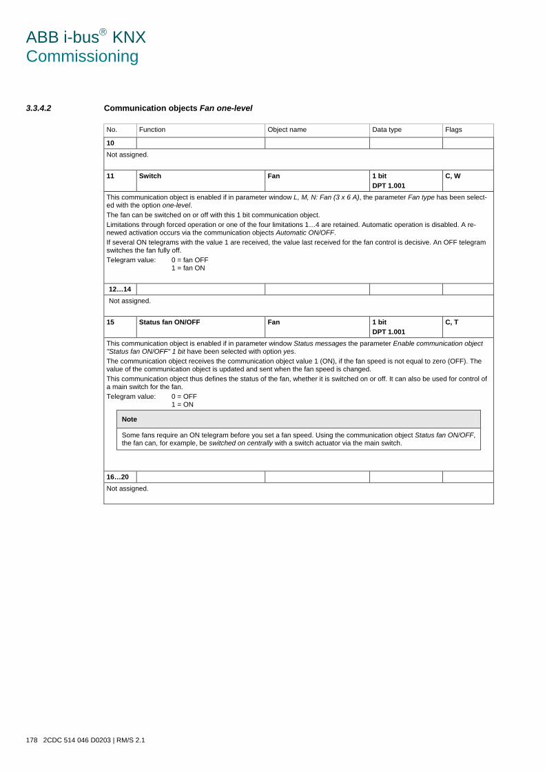
ABB i-bus KNX Commissioning
178 2CDC 514 046 D0203 | RM/S 2.1
3.3.4.2 Communication objects Fan one-level
No. Function Object name Data type Flags
10 Not assigned.
11 Switch Fan 1 bit DPT 1.001
C, W
This communication object is enabled if in parameter window L, M, N: Fan (3 x 6 A), the parameter Fan type has been select-ed with the option one-level. The fan can be switched on or off with this 1 bit communication object. Limitations through forced operation or one of the four limitations 1…4 are retained. Automatic operation is disabled. A re-newed activation occurs via the communication objects Automatic ON/OFF. If several ON telegrams with the value 1 are received, the value last received for the fan control is decisive. An OFF telegram switches the fan fully off. Telegram value: 0 = fan OFF
1 = fan ON
12…14 Not assigned.
15 Status fan ON/OFF Fan 1 bit DPT 1.001
C, T
This communication object is enabled if in parameter window Status messages the parameter Enable communication object "Status fan ON/OFF" 1 bit have been selected with option yes. The communication object receives the communication object value 1 (ON), if the fan speed is not equal to zero (OFF). The value of the communication object is updated and sent when the fan speed is changed. This communication object thus defines the status of the fan, whether it is switched on or off. It can also be used for control of a main switch for the fan. Telegram value: 0 = OFF
1 = ON
Note
Some fans require an ON telegram before you set a fan speed. Using the communication object Status fan ON/OFF, the fan can, for example, be switched on centrally with a switch actuator via the main switch.
16…20 Not assigned.
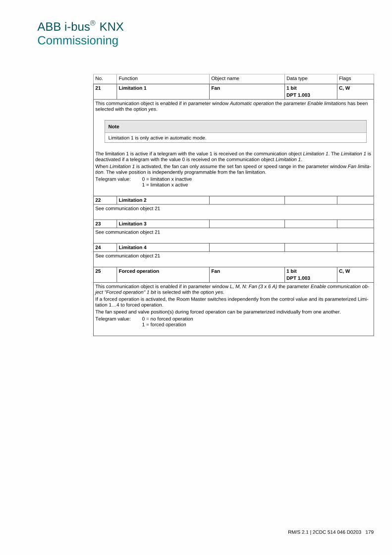
ABB i-bus KNX Commissioning
RM/S 2.1 | 2CDC 514 046 D0203 179
No. Function Object name Data type Flags
21 Limitation 1 Fan 1 bit DPT 1.003
C, W
This communication object is enabled if in parameter window Automatic operation the parameter Enable limitations has been selected with the option yes.
Note
Limitation 1 is only active in automatic mode.
The limitation 1 is active if a telegram with the value 1 is received on the communication object Limitation 1. The Limitation 1 is deactivated if a telegram with the value 0 is received on the communication object Limitation 1. When Limitation 1 is activated, the fan can only assume the set fan speed or speed range in the parameter window Fan limita-tion. The valve position is independently programmable from the fan limitation. Telegram value: 0 = limitation x inactive
1 = limitation x active
22 Limitation 2 See communication object 21
23 Limitation 3 See communication object 21
24 Limitation 4 See communication object 21
25 Forced operation Fan 1 bit DPT 1.003
C, W
This communication object is enabled if in parameter window L, M, N: Fan (3 x 6 A) the parameter Enable communication ob-ject "Forced operation" 1 bit is selected with the option yes. If a forced operation is activated, the Room Master switches independently from the control value and its parameterized Limi-tation 1…4 to forced operation. The fan speed and valve position(s) during forced operation can be parameterized individually from one another. Telegram value: 0 = no forced operation
1 = forced operation
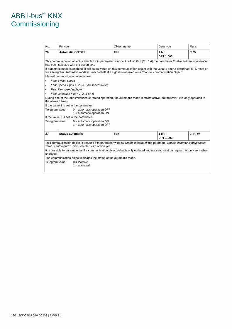
ABB i-bus KNX Commissioning
180 2CDC 514 046 D0203 | RM/S 2.1
No. Function Object name Data type Flags
26 Automatic ON/OFF Fan 1 bit DPT 1.003
C, W
This communication object is enabled if in parameter window L, M, N: Fan (3 x 6 A) the parameter Enable automatic operation has been selected with the option yes. If automatic mode is enabled, it will be activated on this communication object with the value 1 after a download, ETS reset or via a telegram. Automatic mode is switched off, if a signal is received on a “manual communication object”. Manual communication objects are: • Fan: Switch speed • Fan: Speed x (x = 1, 2, 3), Fan speed switch • Fan: Fan speed up/down • Fan: Limitation x (x = 1, 2, 3 or 4) During one of the four limitations or forced operation, the automatic mode remains active, but however, it is only operated in the allowed limits. If the value 1 is set in the parameter: Telegram value: 0 = automatic operation OFF
1 = automatic operation ON If the value 0 is set in the parameter: Telegram value: 0 = automatic operation ON
1 = automatic operation OFF
27 Status automatic Fan 1 bit DPT 1.003
C, R, W
This communication object is enabled if in parameter window Status messages the parameter Enable communication object "Status automatic" 1 bit is selected with option yes. It is possible to parameterize if a communication object value is only updated and not sent, sent on request, or only sent when changed. The communication object indicates the status of the automatic mode. Telegram value: 0 = inactive
1 = activated
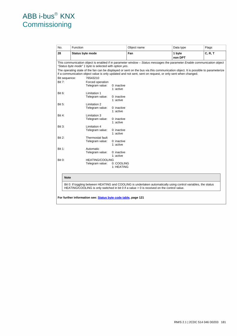
ABB i-bus KNX Commissioning
RM/S 2.1 | 2CDC 514 046 D0203 181
No. Function Object name Data type Flags
28 Status byte mode Fan 1 byte non DPT
C, R, T
This communication object is enabled if in parameter window – Status messages the parameter Enable communication object “Status byte mode" 1 byte is selected with option yes. The operating state of the fan can be displayed or sent on the bus via this communication object. It is possible to parameterize if a communication object value is only updated and not sent, sent on request, or only sent when changed. Bit sequence: 76543210 Bit 7: Forced operation
Telegram value: 0: inactive 1: active
Bit 6: Limitation 1 Telegram value: 0: inactive 1: active
Bit 5: Limitation 2 Telegram value: 0: inactive 1: active
Bit 4: Limitation 3 Telegram value: 0: inactive 1: active
Bit 3: Limitation 4 Telegram value: 0: inactive 1: active
Bit 2: Thermostat fault Telegram value: 0: inactive 1: active
Bit 1: Automatic Telegram value: 0: inactive 1: active
Bit 0: HEATING/COOLING Telegram value: 0: COOLING 1: HEATING
Note
Bit 0: If toggling between HEATING and COOLING is undertaken automatically using control variables, the status HEATING/COOLING is only switched in bit 0 if a value > 0 is received on the control value.
For further information see: Status byte code table, page 121
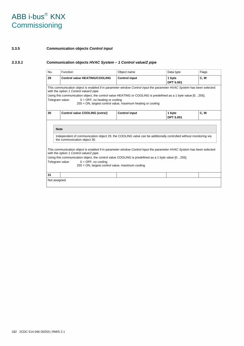
ABB i-bus KNX Commissioning
182 2CDC 514 046 D0203 | RM/S 2.1
3.3.5 Communication objects Control input
3.3.5.1 Communication objects HVAC System – 1 Control value/2 pipe
No. Function Object name Data type Flags
29 Control value HEATING/COOLING Control input 1 byte DPT 5.001
C, W
This communication object is enabled if in parameter window Control input the parameter HVAC System has been selected with the option 1 Control value/2 pipe. Using this communication object, the control value HEATING or COOLING is predefined as a 1 byte value [0…255]. Telegram value: 0 = OFF, no heating or cooling
255 = ON, largest control value, maximum heating or cooling
30 Control value COOLING (extra!) Control input 1 byte DPT 5.001
C, W
Note
Independent of communication object 29, the COOLING valve can be additionally controlled without monitoring via the communication object 30.
This communication object is enabled if in parameter window Control input the parameter HVAC System has been selected with the option 1 Control value/2 pipe. Using this communication object, the control value COOLING is predefined as a 1 byte value [0…255]. Telegram value: 0 = OFF, no cooling
255 = ON, largest control value, maximum cooling
31 Not assigned.
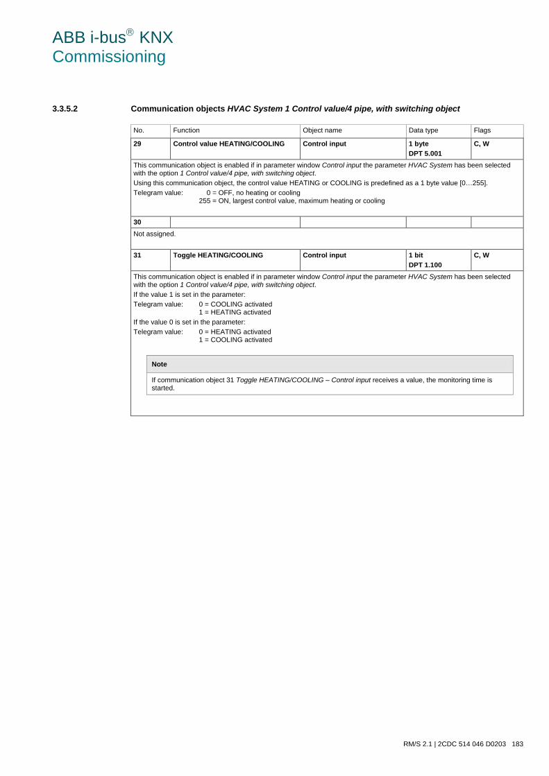
ABB i-bus KNX Commissioning
RM/S 2.1 | 2CDC 514 046 D0203 183
3.3.5.2 Communication objects HVAC System 1 Control value/4 pipe, with switching object
No. Function Object name Data type Flags
29 Control value HEATING/COOLING Control input 1 byte DPT 5.001
C, W
This communication object is enabled if in parameter window Control input the parameter HVAC System has been selected with the option 1 Control value/4 pipe, with switching object. Using this communication object, the control value HEATING or COOLING is predefined as a 1 byte value [0…255]. Telegram value: 0 = OFF, no heating or cooling
255 = ON, largest control value, maximum heating or cooling
30 Not assigned.
31 Toggle HEATING/COOLING Control input 1 bit DPT 1.100
C, W
This communication object is enabled if in parameter window Control input the parameter HVAC System has been selected with the option 1 Control value/4 pipe, with switching object. If the value 1 is set in the parameter: Telegram value: 0 = COOLING activated
1 = HEATING activated If the value 0 is set in the parameter: Telegram value: 0 = HEATING activated
1 = COOLING activated
Note
If communication object 31 Toggle HEATING/COOLING – Control input receives a value, the monitoring time is started.

ABB i-bus KNX Commissioning
184 2CDC 514 046 D0203 | RM/S 2.1
3.3.5.3 Communication objects HVAC System – 2 Control values/2 pipe
No. Function Object name Data type Flags
29 Control value HEATING Control input 1 byte DPT 5.001
C, W
This communication object is enabled if in parameter window Control input the parameter HVAC System has been selected with the option 2 Control values/2 pipe. Using this communication object, the control value HEATING is predefined as a 1 byte value [0…255]. Telegram value: 0 = OFF, no heating
255 = ON, largest control value, maximum heating
30 Control value COOLING Control input 1 byte DPT 5.001
C, W
This communication object is enabled if in parameter window Control input the parameter HVAC System has been selected with the option 2 Control value/2 pipe. Using this communication object, the control value COOLING is predefined as a 1 byte value [0…255]. Telegram value: 0 = OFF, no cooling
255 = ON, largest control value, maximum cooling
31 Not assigned.
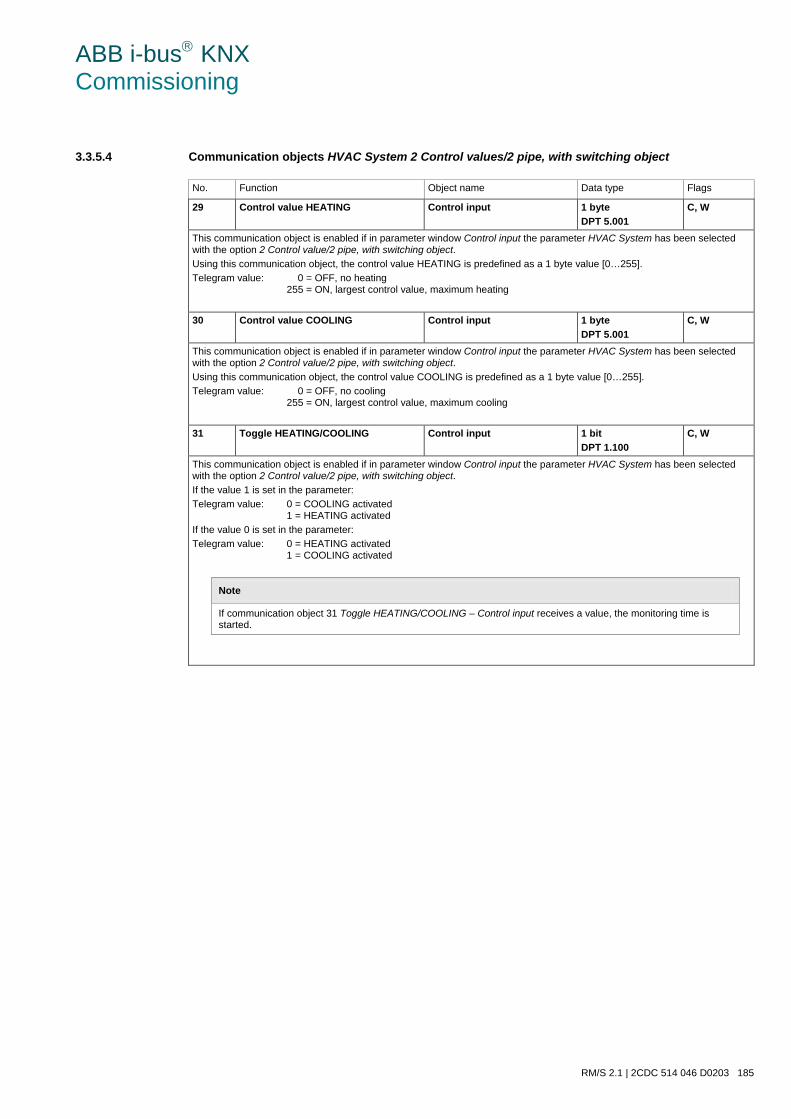
ABB i-bus KNX Commissioning
RM/S 2.1 | 2CDC 514 046 D0203 185
3.3.5.4 Communication objects HVAC System 2 Control values/2 pipe, with switching object
No. Function Object name Data type Flags
29 Control value HEATING Control input 1 byte DPT 5.001
C, W
This communication object is enabled if in parameter window Control input the parameter HVAC System has been selected with the option 2 Control value/2 pipe, with switching object. Using this communication object, the control value HEATING is predefined as a 1 byte value [0…255]. Telegram value: 0 = OFF, no heating
255 = ON, largest control value, maximum heating
30 Control value COOLING Control input 1 byte DPT 5.001
C, W
This communication object is enabled if in parameter window Control input the parameter HVAC System has been selected with the option 2 Control value/2 pipe, with switching object. Using this communication object, the control value COOLING is predefined as a 1 byte value [0…255]. Telegram value: 0 = OFF, no cooling
255 = ON, largest control value, maximum cooling
31 Toggle HEATING/COOLING Control input 1 bit DPT 1.100
C, W
This communication object is enabled if in parameter window Control input the parameter HVAC System has been selected with the option 2 Control value/2 pipe, with switching object. If the value 1 is set in the parameter: Telegram value: 0 = COOLING activated
1 = HEATING activated If the value 0 is set in the parameter: Telegram value: 0 = HEATING activated
1 = COOLING activated
Note
If communication object 31 Toggle HEATING/COOLING – Control input receives a value, the monitoring time is started.
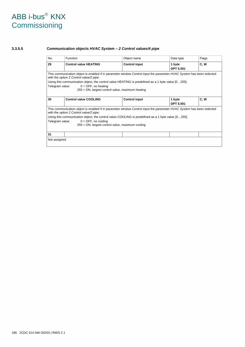
ABB i-bus KNX Commissioning
186 2CDC 514 046 D0203 | RM/S 2.1
3.3.5.5 Communication objects HVAC System – 2 Control values/4 pipe
No. Function Object name Data type Flags
29 Control value HEATING Control input 1 byte DPT 5.001
C, W
This communication object is enabled if in parameter window Control input the parameter HVAC System has been selected with the option 2 Control value/2 pipe. Using this communication object, the control value HEATING is predefined as a 1 byte value [0…255]. Telegram value: 0 = OFF, no heating
255 = ON, largest control value, maximum heating
30 Control value COOLING Control input 1 byte DPT 5.001
C, W
This communication object is enabled if in parameter window Control input the parameter HVAC System has been selected with the option 2 Control value/2 pipe. Using this communication object, the control value COOLING is predefined as a 1 byte value [0…255]. Telegram value: 0 = OFF, no cooling
255 = ON, largest control value, maximum cooling
31 Not assigned.
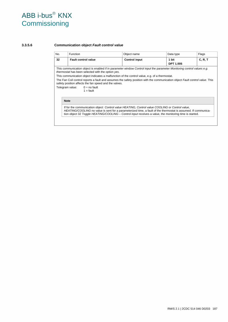
ABB i-bus KNX Commissioning
RM/S 2.1 | 2CDC 514 046 D0203 187
3.3.5.6 Communication object Fault control value
No. Function Object name Data type Flags
32 Fault control value Control input 1 bit DPT 1.005
C, R, T
This communication object is enabled if in parameter window Control input the parameter Monitoring control values e.g. thermostat has been selected with the option yes. This communication object indicates a malfunction of the control value, e.g. of a thermostat. The Fan Coil control reports a fault and assumes the safety position with the communication object Fault control value. This safety position affects the fan speed and the valves. Telegram value: 0 = no fault
1 = fault
Note
If for the communication object Control value HEATING, Control value COOLING or Control value, HEATING/COOLING no value is sent for a parameterized time, a fault of the thermostat is assumed. If communica-tion object 32 Toggle HEATING/COOLING – Control input receives a value, the monitoring time is started.
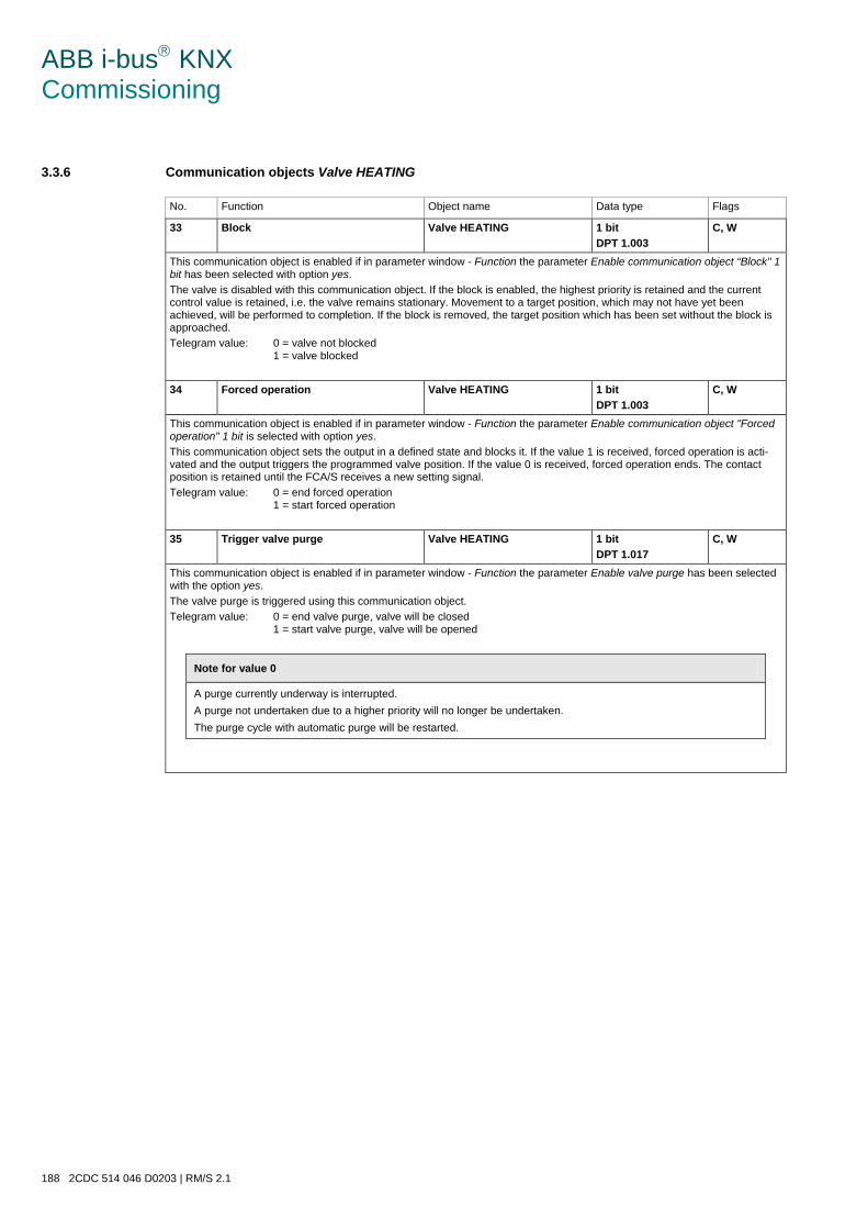
ABB i-bus KNX Commissioning
188 2CDC 514 046 D0203 | RM/S 2.1
3.3.6 Communication objects Valve HEATING
No. Function Object name Data type Flags
33 Block Valve HEATING 1 bit DPT 1.003
C, W
This communication object is enabled if in parameter window - Function the parameter Enable communication object “Block" 1 bit has been selected with option yes. The valve is disabled with this communication object. If the block is enabled, the highest priority is retained and the current control value is retained, i.e. the valve remains stationary. Movement to a target position, which may not have yet been achieved, will be performed to completion. If the block is removed, the target position which has been set without the block is approached. Telegram value: 0 = valve not blocked
1 = valve blocked
34 Forced operation Valve HEATING 1 bit DPT 1.003
C, W
This communication object is enabled if in parameter window - Function the parameter Enable communication object "Forced operation" 1 bit is selected with option yes. This communication object sets the output in a defined state and blocks it. If the value 1 is received, forced operation is acti-vated and the output triggers the programmed valve position. If the value 0 is received, forced operation ends. The contact position is retained until the FCA/S receives a new setting signal. Telegram value: 0 = end forced operation
1 = start forced operation
35 Trigger valve purge Valve HEATING 1 bit DPT 1.017
C, W
This communication object is enabled if in parameter window - Function the parameter Enable valve purge has been selected with the option yes. The valve purge is triggered using this communication object. Telegram value: 0 = end valve purge, valve will be closed
1 = start valve purge, valve will be opened
Note for value 0
A purge currently underway is interrupted. A purge not undertaken due to a higher priority will no longer be undertaken. The purge cycle with automatic purge will be restarted.
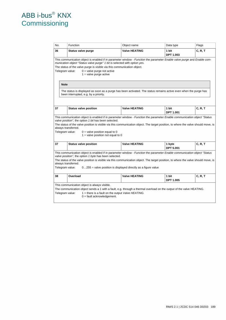
ABB i-bus KNX Commissioning
RM/S 2.1 | 2CDC 514 046 D0203 189
No. Function Object name Data type Flags
36 Status valve purge Valve HEATING 1 bit DPT 1.003
C, R, T
This communication object is enabled if in parameter window - Function the parameter Enable valve purge and Enable com-munication object “Status valve purge" 1 bit is selected with option yes. The status of the valve purge is visible via this communication object. Telegram value: 0 = valve purge not active
1 = valve purge active
Note
The status is displayed as soon as a purge has been activated. The status remains active even when the purge has been interrupted, e.g. by a priority.
37 Status valve position Valve HEATING 1 bit DPT 1.001
C, R, T
This communication object is enabled if in parameter window - Function the parameter Enable communication object "Status valve position", the option 1 bit has been selected. The status of the valve position is visible via this communication object. The target position, to where the valve should move, is always transferred. Telegram value: 0 = valve position equal to 0
1 = valve position not equal to 0
37 Status valve position Valve HEATING 1 byte DPT 5.001
C, R, T
This communication object is enabled if in parameter window - Function the parameter Enable communication object "Status valve position", the option 1 byte has been selected. The status of the valve position is visible via this communication object. The target position, to where the valve should move, is always transferred. Telegram value: 0…255 = valve position is displayed directly as a figure value
38 Overload Valve HEATING 1 bit DPT 1.005
C, R, T
This communication object is always visible. The communication object sends a 1 with a fault, e.g. through a thermal overload on the output of the valve HEATING. Telegram value: 1 = there is a fault on the output Valve HEATING.
0 = fault acknowledgement.

ABB i-bus KNX Commissioning
190 2CDC 514 046 D0203 | RM/S 2.1
3.3.7 Communication objects Valve COOLING
The communication objects of the valve COOLING do not differ from those of the valve HEATING.
The descriptions of the parameter setting options and adjustable communication objects for the Valve COOLING are described under Parameter window O, P: Valve HEATING (0.5 A AC) – 3 point, opening and closing, page 147 or under communication objects Valve HEATING, page 187.
The communication objects Valve COOLING have the nos. 39…44.
ABB i-bus KNX Commissioning
RM/S 2.1 | 2CDC 514 046 D0203 191
3.3.8 Communication objects Inputs a…r
The communication objects of all Inputs do not differentiate from one another and are explained using In-put a.
The descriptions of the parameter setting options of Inputs a…r are described from Parameter windowEnable Inputs a…f on page 34.
The communication objects Input a have the nos. 45…49.
The communication objects Input b have the nos. 50…54.
The communication objects Input c have the nos. 55…59.
The communication objects Input d have the nos. 60…64.
The communication objects Input e have the nos. 65…69.
The communication objects Input f have the nos. 70…74.
The communication objects Input g have the nos. 75…79.
The communication objects Input h have the nos. 80…84.
The communication objects Input i have the nos. 85…89.
The communication objects Input j have the nos. 90…94.
The communication objects Input k have the nos. 95…99.
The communication objects Input l have the nos. 100…104.
The communication objects Input m have the nos. 105…109.
The communication objects Input n have the nos. 110…114.
The communication objects Input o have the nos. 115…119.
The communication objects Input p have the nos. 120…124.
The communication objects Input q have the nos. 125…129.
The communication objects Input r have the nos. 130…134
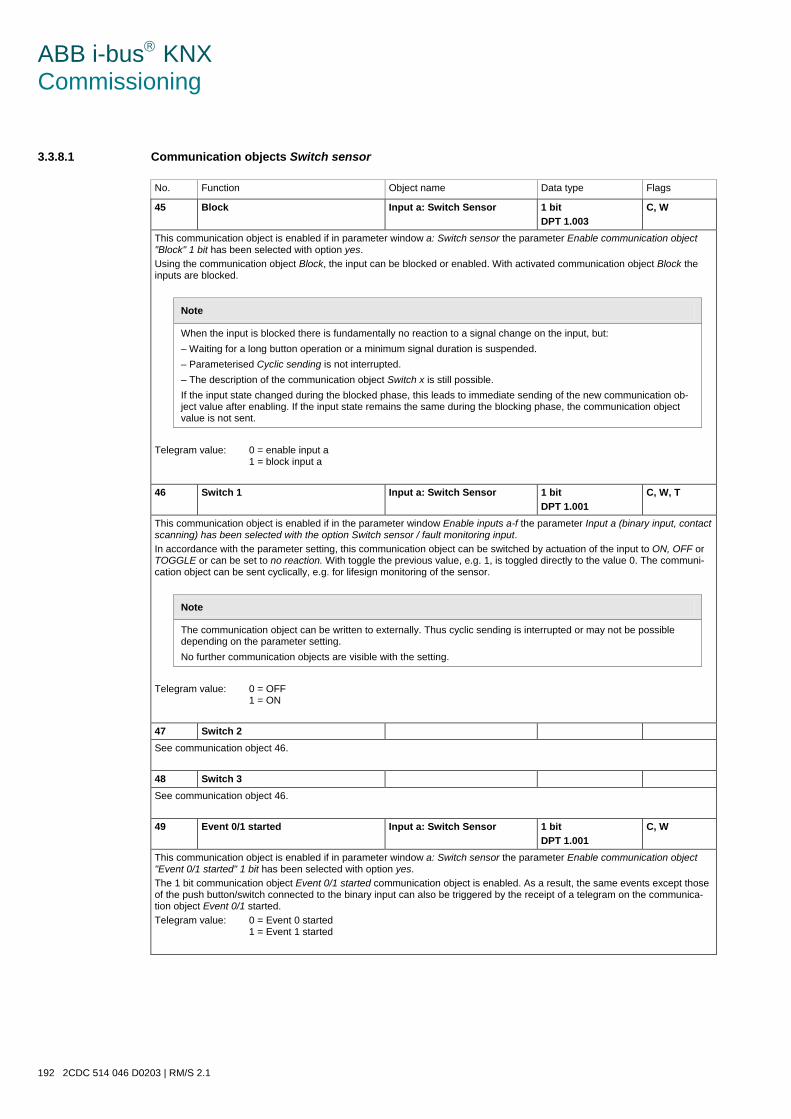
ABB i-bus KNX Commissioning
192 2CDC 514 046 D0203 | RM/S 2.1
3.3.8.1 Communication objects Switch sensor
No. Function Object name Data type Flags
45 Block Input a: Switch Sensor 1 bit DPT 1.003
C, W
This communication object is enabled if in parameter window a: Switch sensor the parameter Enable communication object "Block" 1 bit has been selected with option yes. Using the communication object Block, the input can be blocked or enabled. With activated communication object Block the inputs are blocked.
Note
When the input is blocked there is fundamentally no reaction to a signal change on the input, but: – Waiting for a long button operation or a minimum signal duration is suspended. – Parameterised Cyclic sending is not interrupted. – The description of the communication object Switch x is still possible. If the input state changed during the blocked phase, this leads to immediate sending of the new communication ob-ject value after enabling. If the input state remains the same during the blocking phase, the communication object value is not sent.
Telegram value: 0 = enable input a
1 = block input a
46 Switch 1 Input a: Switch Sensor 1 bit DPT 1.001
C, W, T
This communication object is enabled if in the parameter window Enable inputs a-f the parameter Input a (binary input, contact scanning) has been selected with the option Switch sensor / fault monitoring input. In accordance with the parameter setting, this communication object can be switched by actuation of the input to ON, OFF or TOGGLE or can be set to no reaction. With toggle the previous value, e.g. 1, is toggled directly to the value 0. The communi-cation object can be sent cyclically, e.g. for lifesign monitoring of the sensor.
Note
The communication object can be written to externally. Thus cyclic sending is interrupted or may not be possible depending on the parameter setting. No further communication objects are visible with the setting.
Telegram value: 0 = OFF
1 = ON
47 Switch 2 See communication object 46.
48 Switch 3 See communication object 46.
49 Event 0/1 started Input a: Switch Sensor 1 bit DPT 1.001
C, W
This communication object is enabled if in parameter window a: Switch sensor the parameter Enable communication object "Event 0/1 started" 1 bit has been selected with option yes. The 1 bit communication object Event 0/1 started communication object is enabled. As a result, the same events except those of the push button/switch connected to the binary input can also be triggered by the receipt of a telegram on the communica-tion object Event 0/1 started. Telegram value: 0 = Event 0 started
1 = Event 1 started
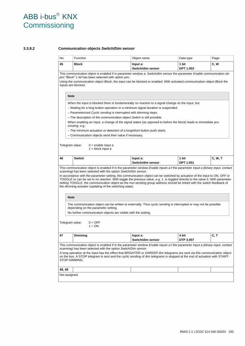
ABB i-bus KNX Commissioning
RM/S 2.1 | 2CDC 514 046 D0203 193
3.3.8.2 Communication objects Switch/Dim sensor
No. Function Object name Data type Flags
45 Block Input a: Switch/dim sensor
1 bit DPT 1.003
C, W
This communication object is enabled if in parameter window a: Switch/dim sensor the parameter Enable communication ob-ject "Block" 1 bit has been selected with option yes. Using the communication object Block, the input can be blocked or enabled. With activated communication object Block the inputs are blocked.
Note
When the input is blocked there is fundamentally no reaction to a signal change on the input, but: – Waiting for a long button operation or a minimum signal duration is suspended. – Parameterized Cyclic sending is interrupted with dimming steps. – The description of the communication object Switch is still possible. When enabling an input, a change of the signal states (as opposed to before the block) leads to immediate pro-cessing, e.g.: – The minimum actuation or detection of a long/short button push starts. – Communication objects send their value if necessary.
Telegram value: 0 = enable input a
1 = block input a
46 Switch Input a: Switch/dim sensor
1 bit DPT 1.001
C, W, T
This communication object is enabled if in the parameter window Enable inputs a-f the parameter Input a (binary input, contact scanning) has been selected with the option Switch/Dim sensor. In accordance with the parameter setting, this communication object can be switched by actuation of the input to ON, OFF or TOGGLE or can be set to no reaction. With toggle the previous value, e.g. 1, is toggled directly to the value 0. With parameter setting TOGGLE, the communication object as the non-sending group address should be linked with the switch feedback of the dimming actuator (updating of the switching state).
Note
The communication object can be written to externally. Thus cyclic sending is interrupted or may not be possible depending on the parameter setting. No further communication objects are visible with the setting.
Telegram value: 0 = OFF
1 = ON
47 Dimming Input a: Switch/dim sensor
4 bit DTP 3.007
C, T
This communication object is enabled if in the parameter window Enable inputs a-f the parameter Input a (binary input, contact scanning) has been selected with the option Switch/Dim sensor. A long operation at the input has the effect that BRIGHTER or DARKER dim telegrams are sent via this communication object on the bus. A STOP telegram is sent and the cyclic sending of dim telegrams is stopped at the end of actuation with START-STOP-DIMMING.
48, 49 Not assigned.
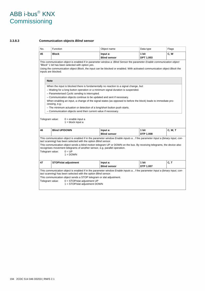
ABB i-bus KNX Commissioning
194 2CDC 514 046 D0203 | RM/S 2.1
3.3.8.3 Communication objects Blind sensor
No. Function Object name Data type Flags
45 Block Input a: Blind sensor
1 bit DPT 1.003
C, W
This communication object is enabled if in parameter window a: Blind Sensor the parameter Enable communication object "Block" 1 bit has been selected with option yes. Using the communication object Block, the input can be blocked or enabled. With activated communication object Block the inputs are blocked.
Note
When the input is blocked there is fundamentally no reaction to a signal change, but: – Waiting for a long button operation or a minimum signal duration is suspended. – Parameterised Cyclic sending is interrupted. – Communication objects continue to be updated and sent if necessary. When enabling an input, a change of the signal states (as opposed to before the block) leads to immediate pro-cessing, e.g.: – The minimum actuation or detection of a long/short button push starts. – Communication objects send their current value if necessary.
Telegram value: 0 = enable input a
1 = block input a
46 Blind UP/DOWN Input a: Blind sensor
1 bit DTP 1.008
C, W, T
This communication object is enabled if in the parameter window Enable inputs a…f the parameter Input a (binary input, con-tact scanning) has been selected with the option Blind sensor. This communication object sends a blind motion telegram UP or DOWN on the bus. By receiving telegrams, the device also recognises movement telegrams of another sensor, e.g. parallel operation. Telegram value: 0 = UP
1 = DOWN
47 STOP/slat adjustment Input a: Blind sensor
1 bit DTP 1.007
C, T
This communication object is enabled if in the parameter window Enable inputs a…f the parameter Input a (binary input, con-tact scanning) has been selected with the option Blind sensor. This communication object sends a STOP telegram or slat adjustment. Telegram value: 0 = STOP/slat adjustment UP
1 = STOP/slat adjustment DOWN
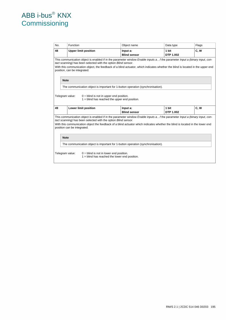
ABB i-bus KNX Commissioning
RM/S 2.1 | 2CDC 514 046 D0203 195
No. Function Object name Data type Flags
48 Upper limit position Input a: Blind sensor
1 bit DTP 1.002
C, W
This communication object is enabled if in the parameter window Enable inputs a…f the parameter Input a (binary input, con-tact scanning) has been selected with the option Blind sensor. With this communication object, the feedback of a blind actuator, which indicates whether the blind is located in the upper end position, can be integrated.
Note
The communication object is important for 1-button operation (synchronisation).
Telegram value: 0 = blind is not in upper end position.
1 = blind has reached the upper end position.
49 Lower limit position Input a: Blind sensor
1 bit DTP 1.002
C, W
This communication object is enabled if in the parameter window Enable inputs a…f the parameter Input a (binary input, con-tact scanning) has been selected with the option Blind sensor. With this communication object the feedback of a blind actuator which indicates whether the blind is located in the lower end position can be integrated.
Note
The communication object is important for 1-button operation (synchronisation).
Telegram value: 0 = blind is not in lower end position.
1 = blind has reached the lower end position.
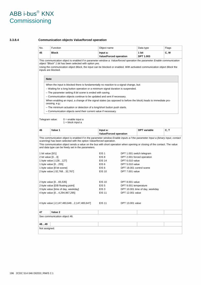
ABB i-bus KNX Commissioning
196 2CDC 514 046 D0203 | RM/S 2.1
3.3.8.4 Communication objects Value/forced operation
No. Function Object name Data type Flags
45 Block Input a: Value/Forced operation
1 bit DPT 1.003
C, W
This communication object is enabled if in parameter window a: Value/forced operation the parameter Enable communication object "Block" 1 bit has been selected with option yes. Using the communication object Block, the input can be blocked or enabled. With activated communication object Block the inputs are blocked.
Note
When the input is blocked there is fundamentally no reaction to a signal change, but: – Waiting for a long button operation or a minimum signal duration is suspended. – The parameter setting 8 bit scene is ended with saving. – Communication objects continue to be updated and sent if necessary. When enabling an input, a change of the signal states (as opposed to before the block) leads to immediate pro-cessing, e.g.: – The minimum actuation or detection of a long/short button push starts. – Communication objects send their current value if necessary.
Telegram value: 0 = enable input a
1 = block input a 46 Value 1 Input a:
Value/Forced operation DPT variable C, T
This communication object is enabled if in the parameter window Enable inputs a-f the parameter Input a (binary input, contact scanning) has been selected with the option Value/forced operation. This communication object sends a value on the bus with short operation when opening or closing of the contact. The value and data type can be freely set in the parameters.
1 bit value [0/1] 2 bit value [0…3] 1 byte value [-128…127] 1 byte value [0…255] 1 byte value [8 bit scene] 2 byte value [-32,768…32,767]
EIS 1 EIS 8 EIS 14 EIS 6 EIS 6 EIS 10
DPT 1.001 switch telegram DPT 2.001 forced operation DPT 6.010 value DPT 5.010 value DPT 18.001 control scene DPT 7.001 value
2 byte value [0…65,535] 2-byte value [EIB floating point] 3 byte value [time of day, weekday] 4 byte value [0…4,294,967,295]
EIS 10 EIS 5 EIS 3 EIS 11
DPT 8.001 value DPT 9.001 temperature DPT 10.001 time of day, weekday DPT 12.001 value
4 byte value [-2,147,483,648…2,147,483,647] EIS 11 DPT 13.001 value
47 Value 2 See communication object 46. 48…49 Not assigned.
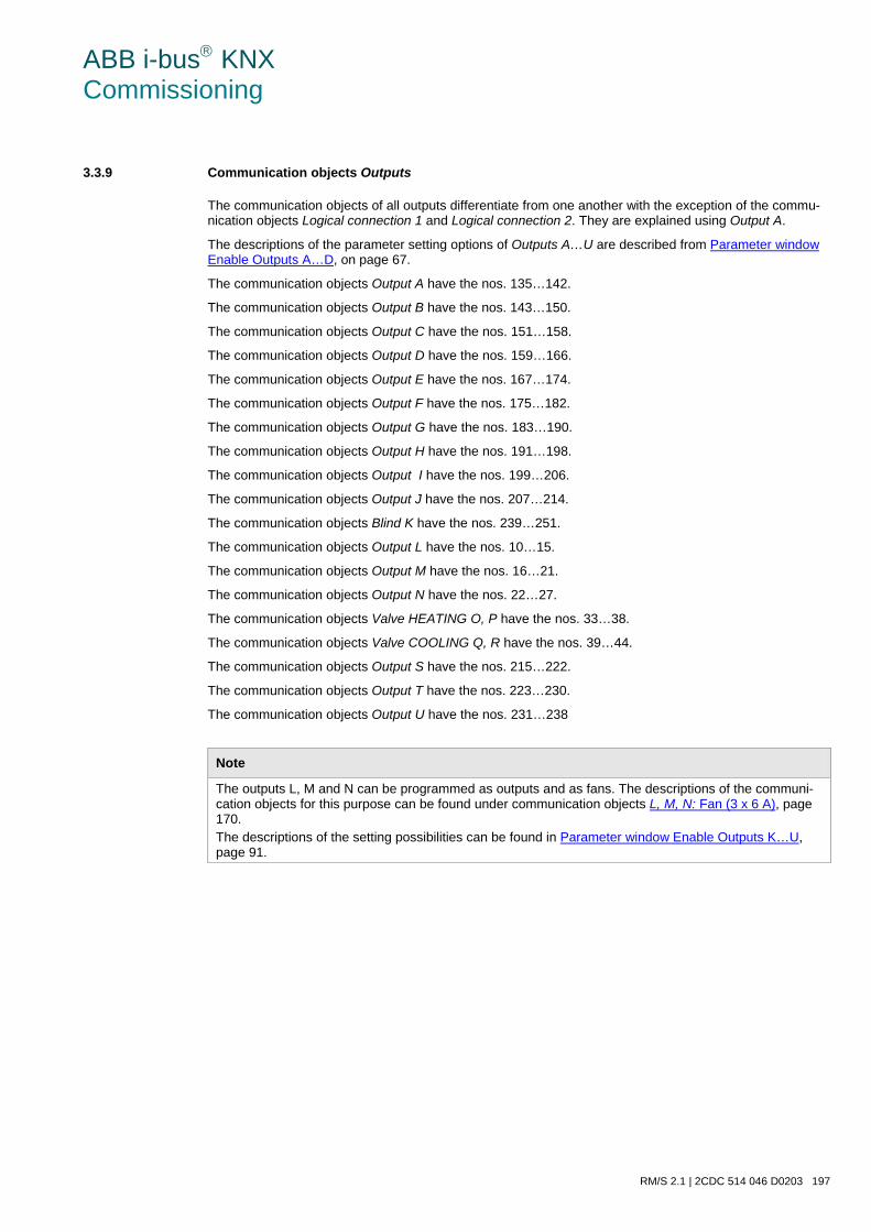
ABB i-bus KNX Commissioning
RM/S 2.1 | 2CDC 514 046 D0203 197
3.3.9 Communication objects Outputs
The communication objects of all outputs differentiate from one another with the exception of the commu-nication objects Logical connection 1 and Logical connection 2. They are explained using Output A.
The descriptions of the parameter setting options of Outputs A…U are described from Parameter window Enable Outputs A…D, on page 67.
The communication objects Output A have the nos. 135…142.
The communication objects Output B have the nos. 143…150.
The communication objects Output C have the nos. 151…158.
The communication objects Output D have the nos. 159…166.
The communication objects Output E have the nos. 167…174.
The communication objects Output F have the nos. 175…182.
The communication objects Output G have the nos. 183…190.
The communication objects Output H have the nos. 191…198.
The communication objects Output I have the nos. 199…206.
The communication objects Output J have the nos. 207…214.
The communication objects Blind K have the nos. 239…251.
The communication objects Output L have the nos. 10…15.
The communication objects Output M have the nos. 16…21.
The communication objects Output N have the nos. 22…27.
The communication objects Valve HEATING O, P have the nos. 33…38.
The communication objects Valve COOLING Q, R have the nos. 39…44.
The communication objects Output S have the nos. 215…222.
The communication objects Output T have the nos. 223…230.
The communication objects Output U have the nos. 231…238
Note
The outputs L, M and N can be programmed as outputs and as fans. The descriptions of the communi-cation objects for this purpose can be found under communication objects L, M, N: Fan (3 x 6 A), page 170. The descriptions of the setting possibilities can be found in Parameter window Enable Outputs K…U, page 91.
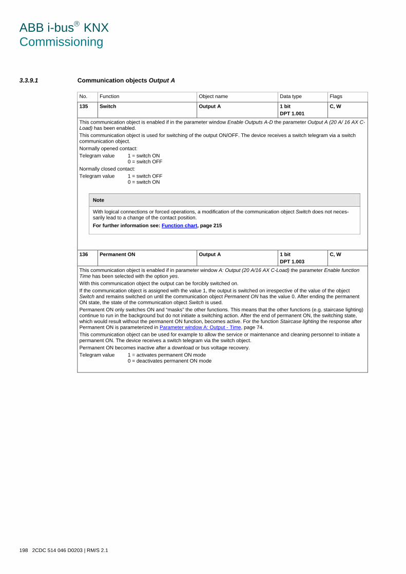
ABB i-bus KNX Commissioning
198 2CDC 514 046 D0203 | RM/S 2.1
3.3.9.1 Communication objects Output A
No. Function Object name Data type Flags
135 Switch Output A 1 bit DPT 1.001
C, W
This communication object is enabled if in the parameter window Enable Outputs A-D the parameter Output A (20 A/ 16 AX C-Load) has been enabled. This communication object is used for switching of the output ON/OFF. The device receives a switch telegram via a switch communication object. Normally opened contact: Telegram value 1 = switch ON
0 = switch OFF Normally closed contact: Telegram value 1 = switch OFF
0 = switch ON
Note
With logical connections or forced operations, a modification of the communication object Switch does not neces-sarily lead to a change of the contact position. For further information see: Function chart, page 215
136 Permanent ON Output A 1 bit DPT 1.003
C, W
This communication object is enabled if in parameter window A: Output (20 A/16 AX C-Load) the parameter Enable function Time has been selected with the option yes. With this communication object the output can be forcibly switched on. If the communication object is assigned with the value 1, the output is switched on irrespective of the value of the object Switch and remains switched on until the communication object Permanent ON has the value 0. After ending the permanent ON state, the state of the communication object Switch is used. Permanent ON only switches ON and “masks” the other functions. This means that the other functions (e.g. staircase lighting) continue to run in the background but do not initiate a switching action. After the end of permanent ON, the switching state, which would result without the permanent ON function, becomes active. For the function Staircase lighting the response after Permanent ON is parameterized in Parameter window A: Output - Time, page 74. This communication object can be used for example to allow the service or maintenance and cleaning personnel to initiate a permanent ON. The device receives a switch telegram via the switch object. Permanent ON becomes inactive after a download or bus voltage recovery. Telegram value 1 = activates permanent ON mode
0 = deactivates permanent ON mode
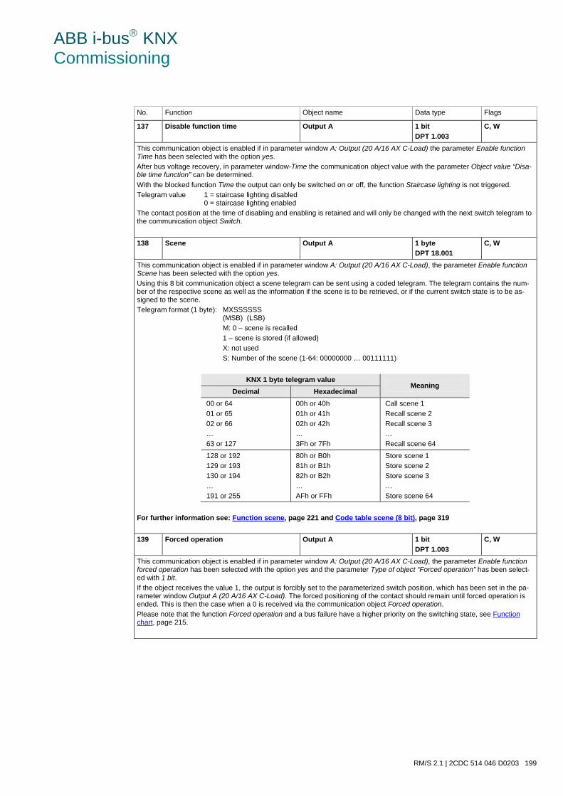
ABB i-bus KNX Commissioning
RM/S 2.1 | 2CDC 514 046 D0203 199
No. Function Object name Data type Flags
137 Disable function time Output A 1 bit DPT 1.003
C, W
This communication object is enabled if in parameter window A: Output (20 A/16 AX C-Load) the parameter Enable function Time has been selected with the option yes. After bus voltage recovery, in parameter window-Time the communication object value with the parameter Object value “Disa-ble time function” can be determined. With the blocked function Time the output can only be switched on or off, the function Staircase lighting is not triggered. Telegram value 1 = staircase lighting disabled
0 = staircase lighting enabled The contact position at the time of disabling and enabling is retained and will only be changed with the next switch telegram to the communication object Switch.
138 Scene Output A 1 byte DPT 18.001
C, W
This communication object is enabled if in parameter window A: Output (20 A/16 AX C-Load), the parameter Enable function Scene has been selected with the option yes. Using this 8 bit communication object a scene telegram can be sent using a coded telegram. The telegram contains the num-ber of the respective scene as well as the information if the scene is to be retrieved, or if the current switch state is to be as-signed to the scene. Telegram format (1 byte): MXSSSSSS
(MSB) (LSB) M: 0 – scene is recalled 1 – scene is stored (if allowed) X: not used S: Number of the scene (1-64: 00000000 … 00111111)
KNX 1 byte telegram value Meaning
Decimal Hexadecimal 00 or 64 01 or 65 02 or 66 … 63 or 127
00h or 40h 01h or 41h 02h or 42h … 3Fh or 7Fh
Call scene 1 Recall scene 2 Recall scene 3 … Recall scene 64
128 or 192 129 or 193 130 or 194 … 191 or 255
80h or B0h 81h or B1h 82h or B2h … AFh or FFh
Store scene 1 Store scene 2 Store scene 3 … Store scene 64
For further information see: Function scene, page 221 and Code table scene (8 bit), page 319
139 Forced operation Output A 1 bit DPT 1.003
C, W
This communication object is enabled if in parameter window A: Output (20 A/16 AX C-Load), the parameter Enable function forced operation has been selected with the option yes and the parameter Type of object “Forced operation” has been select-ed with 1 bit. If the object receives the value 1, the output is forcibly set to the parameterized switch position, which has been set in the pa-rameter window Output A (20 A/16 AX C-Load). The forced positioning of the contact should remain until forced operation is ended. This is then the case when a 0 is received via the communication object Forced operation. Please note that the function Forced operation and a bus failure have a higher priority on the switching state, see Function chart, page 215.
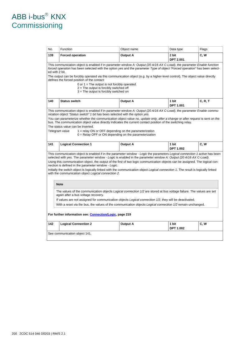
ABB i-bus KNX Commissioning
200 2CDC 514 046 D0203 | RM/S 2.1
No. Function Object name Data type Flags
139 Forced operation Output A 2 bit DPT 2.001
C, W
This communication object is enabled if in parameter window A: Output (20 A/16 AX C-Load), the parameter Enable function forced operation has been selected with the option yes and the parameter Type of object “Forced operation” has been select-ed with 2 bit. The output can be forcibly operated via this communication object (e.g. by a higher-level control). The object value directly defines the forced position of the contact: 0 or 1 = The output is not forcibly operated.
2 = The output is forcibly switched off 3 = The output is forcibly switched on
140 Status switch Output A 1 bit DPT 1.001
C, R, T
This communication object is enabled if in parameter window A: Output (20 A/16 AX C-Load), the parameter Enable commu-nication object “Status switch” 1 bit has been selected with the option yes. You can parameterize whether the communication object value no, update only, after a change or after request is sent on the bus. The communication object value directly indicates the current contact position of the switching relay. The status value can be inverted. Telegram value 1 = relay ON or OFF depending on the parameterization
0 = Relay OFF or ON depending on the parameterization
141 Logical Connection 1 Output A 1 bit DPT 1.002
C, W
This communication object is enabled if in the parameter window - Logic the parameters Logical connection 1 active has been selected with yes. The parameter window - Logic is enabled in the parameter window A: Output (20 A/16 AX C-Load). Using this communication object, the output of the first of two logic communication objects can be assigned. The logical con-nection is defined in the parameter window - Logic. Initially the switch object is logically linked with the communication object Logical connection 1. The result is logically linked with the communication object Logical connection 2.
Note
The values of the communication objects Logical connection 1/2 are stored at bus voltage failure. The values are set again after a bus voltage recovery. If values are not assigned for communication objects Logical connection 1/2, they will be deactivated. With a reset via the bus, the values of the communication objects Logical connection 1/2 remain unchanged.
For further information see: Connection/Logic, page 219
142 Logical Connection 2 Output A 1 bit DPT 1.002
C, W
See communication object 141.
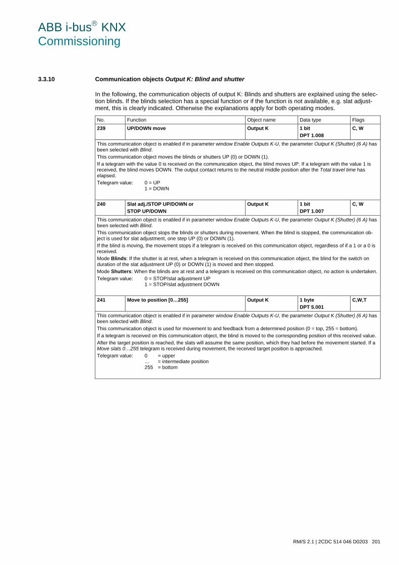
ABB i-bus KNX Commissioning
RM/S 2.1 | 2CDC 514 046 D0203 201
3.3.10 Communication objects Output K: Blind and shutter
In the following, the communication objects of output K: Blinds and shutters are explained using the selec-tion blinds. If the blinds selection has a special function or if the function is not available, e.g. slat adjust-ment, this is clearly indicated. Otherwise the explanations apply for both operating modes.
No. Function Object name Data type Flags
239 UP/DOWN move Output K 1 bit DPT 1.008
C, W
This communication object is enabled if in parameter window Enable Outputs K-U, the parameter Output K (Shutter) (6 A) has been selected with Blind. This communication object moves the blinds or shutters UP (0) or DOWN (1). If a telegram with the value 0 is received on the communication object, the blind moves UP. If a telegram with the value 1 is received, the blind moves DOWN. The output contact returns to the neutral middle position after the Total travel time has elapsed. Telegram value: 0 = UP
1 = DOWN
240 Slat adj./STOP UP/DOWN or STOP UP/DOWN
Output K 1 bit DPT 1.007
C, W
This communication object is enabled if in parameter window Enable Outputs K-U, the parameter Output K (Shutter) (6 A) has been selected with Blind. This communication object stops the blinds or shutters during movement. When the blind is stopped, the communication ob-ject is used for slat adjustment, one step UP (0) or DOWN (1). If the blind is moving, the movement stops if a telegram is received on this communication object, regardless of if a 1 or a 0 is received. Mode Blinds: If the shutter is at rest, when a telegram is received on this communication object, the blind for the switch on duration of the slat adjustment UP (0) or DOWN (1) is moved and then stopped. Mode Shutters: When the blinds are at rest and a telegram is received on this communication object, no action is undertaken. Telegram value: 0 = STOP/slat adjustment UP
1 = STOP/slat adjustment DOWN
241 Move to position [0…255] Output K 1 byte DPT 5.001
C,W,T
This communication object is enabled if in parameter window Enable Outputs K-U, the parameter Output K (Shutter) (6 A) has been selected with Blind. This communication object is used for movement to and feedback from a determined position (0 = top, 255 = bottom). If a telegram is received on this communication object, the blind is moved to the corresponding position of this received value. After the target position is reached, the slats will assume the same position, which they had before the movement started. If a Move slats 0…255 telegram is received during movement, the received target position is approached. Telegram value: 0 = upper
… = intermediate position 255 = bottom
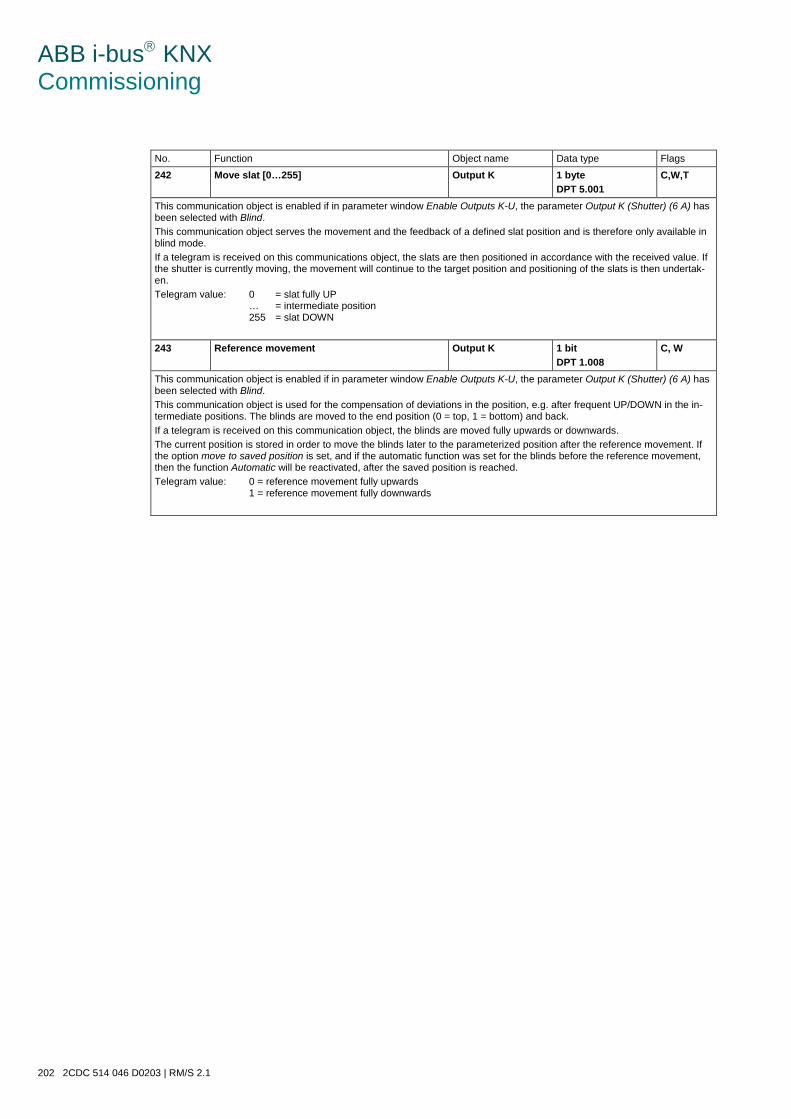
ABB i-bus KNX Commissioning
202 2CDC 514 046 D0203 | RM/S 2.1
No. Function Object name Data type Flags
242 Move slat [0…255] Output K 1 byte DPT 5.001
C,W,T
This communication object is enabled if in parameter window Enable Outputs K-U, the parameter Output K (Shutter) (6 A) has been selected with Blind. This communication object serves the movement and the feedback of a defined slat position and is therefore only available in blind mode. If a telegram is received on this communications object, the slats are then positioned in accordance with the received value. If the shutter is currently moving, the movement will continue to the target position and positioning of the slats is then undertak-en. Telegram value: 0 = slat fully UP
… = intermediate position 255 = slat DOWN
243 Reference movement Output K 1 bit DPT 1.008
C, W
This communication object is enabled if in parameter window Enable Outputs K-U, the parameter Output K (Shutter) (6 A) has been selected with Blind. This communication object is used for the compensation of deviations in the position, e.g. after frequent UP/DOWN in the in-termediate positions. The blinds are moved to the end position (0 = top, 1 = bottom) and back. If a telegram is received on this communication object, the blinds are moved fully upwards or downwards. The current position is stored in order to move the blinds later to the parameterized position after the reference movement. If the option move to saved position is set, and if the automatic function was set for the blinds before the reference movement, then the function Automatic will be reactivated, after the saved position is reached. Telegram value: 0 = reference movement fully upwards
1 = reference movement fully downwards
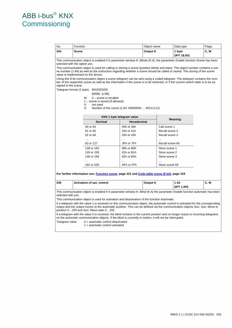
ABB i-bus KNX Commissioning
RM/S 2.1 | 2CDC 514 046 D0203 203
No. Function Object name Data type Flags
244 Scene Output K 1 byte DPT 18.001
C, W
This communication object is enabled if in parameter window K: Blinds (6 A), the parameter Enable function Scene has been selected with the option yes. This communication object is used for calling or storing a scene (position blinds and slats). The object number contains a sce-ne number (1-64) as well as the instruction regarding whether a scene should be called or stored. The storing of the scene value is implemented on the device. Using this 8 bit communication object a scene telegram can be sent using a coded telegram. The telegram contains the num-ber of the respective scene as well as the information if the scene is to be retrieved, or if the current switch state is to be as-signed to the scene. Telegram format (1 byte): MXSSSSSS (MSB) (LSB) M: 0 – scene is recalled
1 – scene is stored (if allowed) X: not used S: Number of the scene (1-64: 00000000 … 00111111)
KNX 1 byte telegram value
Meaning Decimal Hexadecimal
00 or 64 01 or 65 02 or 66 … 63 or 127
00h or 40h 01h or 41h 02h or 42h … 3Fh or 7Fh
Call scene 1 Recall scene 2 Recall scene 3 … Recall scene 64
128 or 192 129 or 193 130 or 194 … 191 or 255
80h or B0h 81h or B1h 82h or B2h … AFh or FFh
Store scene 1 Store scene 2 Store scene 3 … Store scene 64
For further information see: Function scene, page 221 and Code table scene (8 bit), page 319
245 Activation of aut. control Output K 1 bit DPT 1.003
C, W
This communication object is enabled if in parameter window K: Blind (6 A) the parameter Enable function automatic has been selected with yes. This communication object is used for activation and deactivation of the function Automatic. If a telegram with the value 1 is received on this communication object, the automatic control is activated for the corresponding output and the output moves to the automatic position. This can be defined via the communication objects Sun, Sun: Move to position 0…255 and Sun: Move slats 0…255. If a telegram with the value 0 is received, the blind remains in the current position and no longer reacts to incoming telegrams on the automatic communication objects. If the blind is currently in motion, it will not be interrupted. Telegram value: 0 = automatic control deactivated
1 = automatic control activated
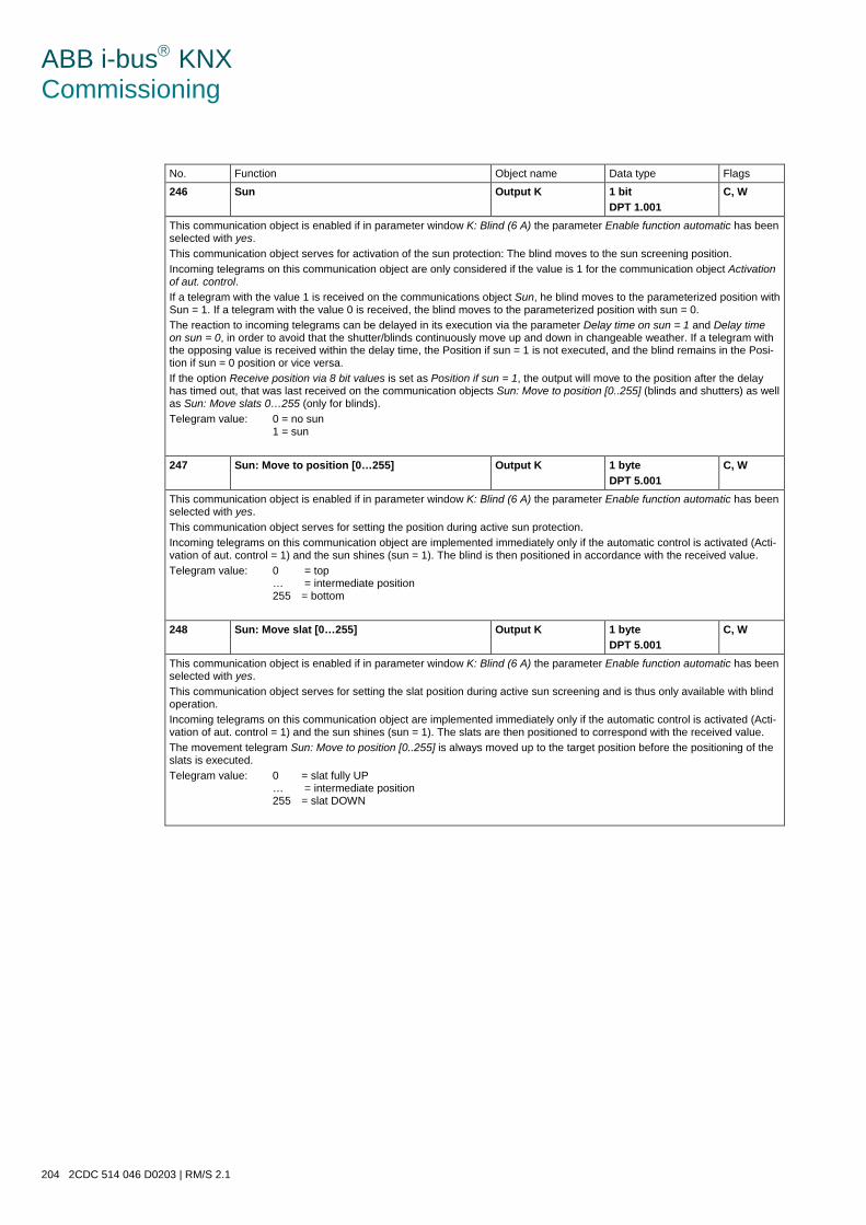
ABB i-bus KNX Commissioning
204 2CDC 514 046 D0203 | RM/S 2.1
No. Function Object name Data type Flags
246 Sun Output K 1 bit DPT 1.001
C, W
This communication object is enabled if in parameter window K: Blind (6 A) the parameter Enable function automatic has been selected with yes. This communication object serves for activation of the sun protection: The blind moves to the sun screening position. Incoming telegrams on this communication object are only considered if the value is 1 for the communication object Activation of aut. control. If a telegram with the value 1 is received on the communications object Sun, he blind moves to the parameterized position with Sun = 1. If a telegram with the value 0 is received, the blind moves to the parameterized position with sun = 0. The reaction to incoming telegrams can be delayed in its execution via the parameter Delay time on sun = 1 and Delay time on sun = 0, in order to avoid that the shutter/blinds continuously move up and down in changeable weather. If a telegram with the opposing value is received within the delay time, the Position if sun = 1 is not executed, and the blind remains in the Posi-tion if sun = 0 position or vice versa. If the option Receive position via 8 bit values is set as Position if sun = 1, the output will move to the position after the delay has timed out, that was last received on the communication objects Sun: Move to position [0..255] (blinds and shutters) as well as Sun: Move slats 0…255 (only for blinds). Telegram value: 0 = no sun
1 = sun
247 Sun: Move to position [0…255] Output K 1 byte DPT 5.001
C, W
This communication object is enabled if in parameter window K: Blind (6 A) the parameter Enable function automatic has been selected with yes. This communication object serves for setting the position during active sun protection. Incoming telegrams on this communication object are implemented immediately only if the automatic control is activated (Acti-vation of aut. control = 1) and the sun shines (sun = 1). The blind is then positioned in accordance with the received value. Telegram value: 0 = top
… = intermediate position 255 = bottom
248 Sun: Move slat [0…255] Output K 1 byte DPT 5.001
C, W
This communication object is enabled if in parameter window K: Blind (6 A) the parameter Enable function automatic has been selected with yes. This communication object serves for setting the slat position during active sun screening and is thus only available with blind operation. Incoming telegrams on this communication object are implemented immediately only if the automatic control is activated (Acti-vation of aut. control = 1) and the sun shines (sun = 1). The slats are then positioned to correspond with the received value. The movement telegram Sun: Move to position [0..255] is always moved up to the target position before the positioning of the slats is executed. Telegram value: 0 = slat fully UP
… = intermediate position 255 = slat DOWN
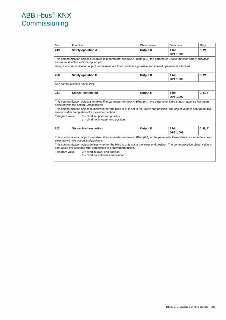
ABB i-bus KNX Commissioning
RM/S 2.1 | 2CDC 514 046 D0203 205
No. Function Object name Data type Flags
249 Safety operation A Output K 1 bit DPT 1.005
C, W
This communication object is enabled if in parameter window K: Blind (6 A) the parameter Enable function safety operation has been selected with the option yes. Using this communication object, movement to a fixed position is possible and normal operation is inhibited.
250 Safety operation B Output K 1 bit DPT 1.005
C, W
See communication object 249.
251 Status Position top Output K 1 bit DPT 1.002
C, R, T
This communication object is enabled if in parameter window K: Blind (6 A) the parameter Extra status response has been selected with the option End positions. This communication object defines whether the blind is or is not in the upper end position. The object value is sent about five seconds after completion of a movement action. Telegram value: 0 = blind in upper end position
1 = blind not in upper end position
252 Status Position bottom Output K 1 bit DPT 1.002
C, R, T
This communication object is enabled if in parameter window K: Blind (6 A) or the parameter Extra status response has been selected with the option End positions. This communication object defines whether the blind is or is not in the lower end position. The communication object value is sent about five seconds after completion of a movement action. Telegram value: 0 = blind in lower end position
1 = blind not in lower end position
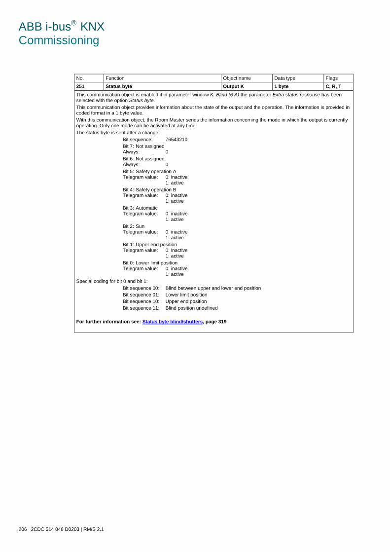
ABB i-bus KNX Commissioning
206 2CDC 514 046 D0203 | RM/S 2.1
No. Function Object name Data type Flags
251 Status byte Output K 1 byte C, R, T This communication object is enabled if in parameter window K: Blind (6 A) the parameter Extra status response has been selected with the option Status byte. This communication object provides information about the state of the output and the operation. The information is provided in coded format in a 1 byte value. With this communication object, the Room Master sends the information concerning the mode in which the output is currently operating. Only one mode can be activated at any time. The status byte is sent after a change. Bit sequence: 76543210 Bit 7: Not assigned
Always: 0 Bit 6: Not assigned
Always: 0 Bit 5: Safety operation A
Telegram value: 0: inactive 1: active
Bit 4: Safety operation B Telegram value: 0: inactive 1: active
Bit 3: Automatic Telegram value: 0: inactive 1: active
Bit 2: Sun Telegram value: 0: inactive 1: active
Bit 1: Upper end position Telegram value: 0: inactive 1: active
Bit 0: Lower limit position Telegram value: 0: inactive 1: active
Special coding for bit 0 and bit 1: Bit sequence 00: Blind between upper and lower end position Bit sequence 01: Lower limit position Bit sequence 10: Upper end position Bit sequence 11: Blind position undefined For further information see: Status byte blind/shutters, page 319
ABB i-bus KNX Planning and Application
RM/S 2.1 | 2CDC 514 046 D0203 207
4 Planning and Application
In this section you will find a description of different types of fans, blowers and fan coil controls. Here also tips and application examples are described for practical use of the device.
4.1 Input
In this chapter the central function and the application explanations for the inputs are explained. The inputs are equipped with the binary contact scanning function.
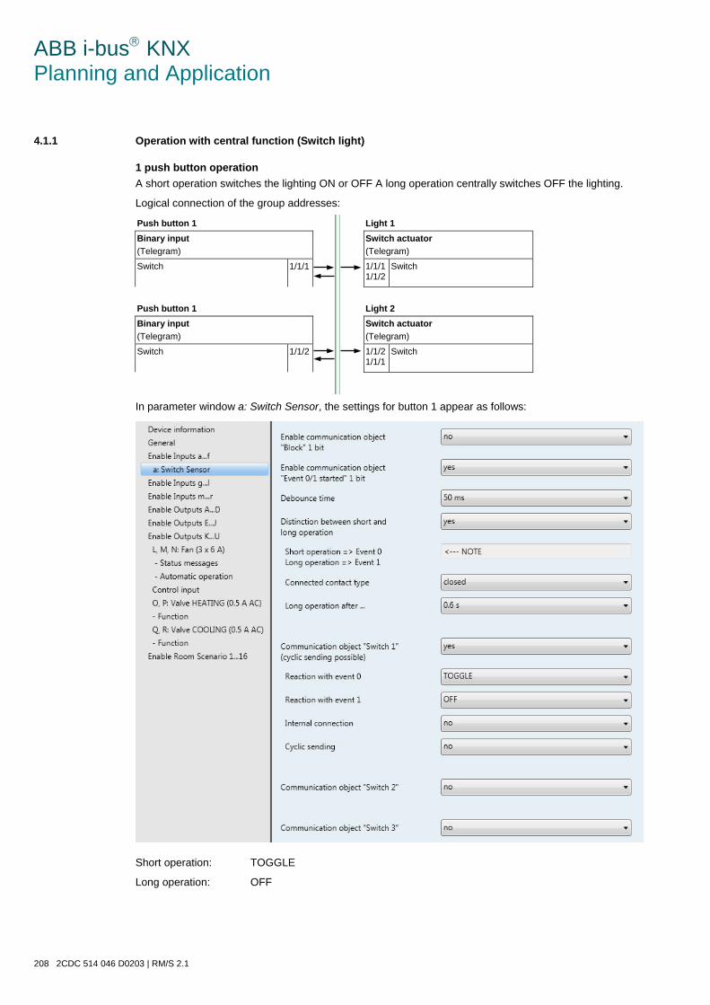
ABB i-bus KNX Planning and Application
208 2CDC 514 046 D0203 | RM/S 2.1
4.1.1 Operation with central function (Switch light)
1 push button operation A short operation switches the lighting ON or OFF A long operation centrally switches OFF the lighting.
Logical connection of the group addresses:
Push button 1 Light 1 Binary input (Telegram)
Switch actuator (Telegram)
Switch 1/1/1 1/1/1 1/1/2
Switch
Push button 1 Light 2 Binary input (Telegram)
Switch actuator (Telegram)
Switch 1/1/2 1/1/2 1/1/1
Switch
In parameter window a: Switch Sensor, the settings for button 1 appear as follows:
Short operation: TOGGLE
Long operation: OFF
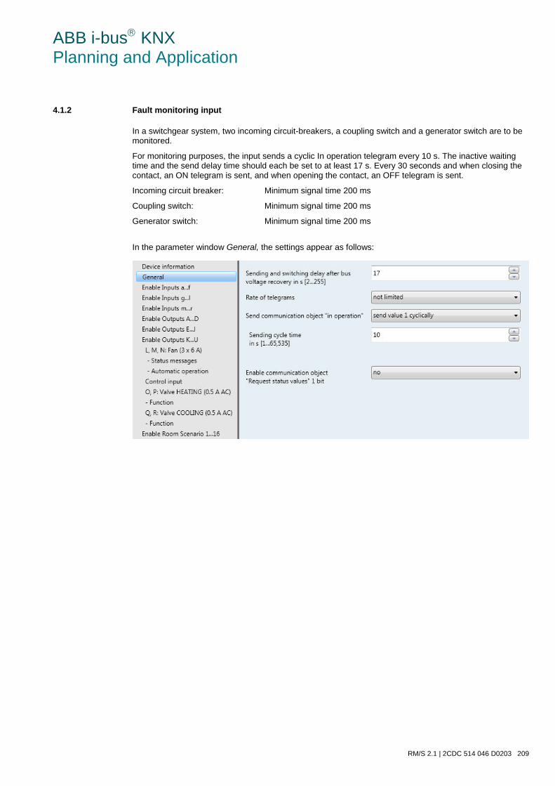
ABB i-bus KNX Planning and Application
RM/S 2.1 | 2CDC 514 046 D0203 209
4.1.2 Fault monitoring input
In a switchgear system, two incoming circuit-breakers, a coupling switch and a generator switch are to be monitored.
For monitoring purposes, the input sends a cyclic In operation telegram every 10 s. The inactive waiting time and the send delay time should each be set to at least 17 s. Every 30 seconds and when closing the contact, an ON telegram is sent, and when opening the contact, an OFF telegram is sent.
Incoming circuit breaker: Minimum signal time 200 ms
Coupling switch: Minimum signal time 200 ms
Generator switch: Minimum signal time 200 ms
In the parameter window General, the settings appear as follows:
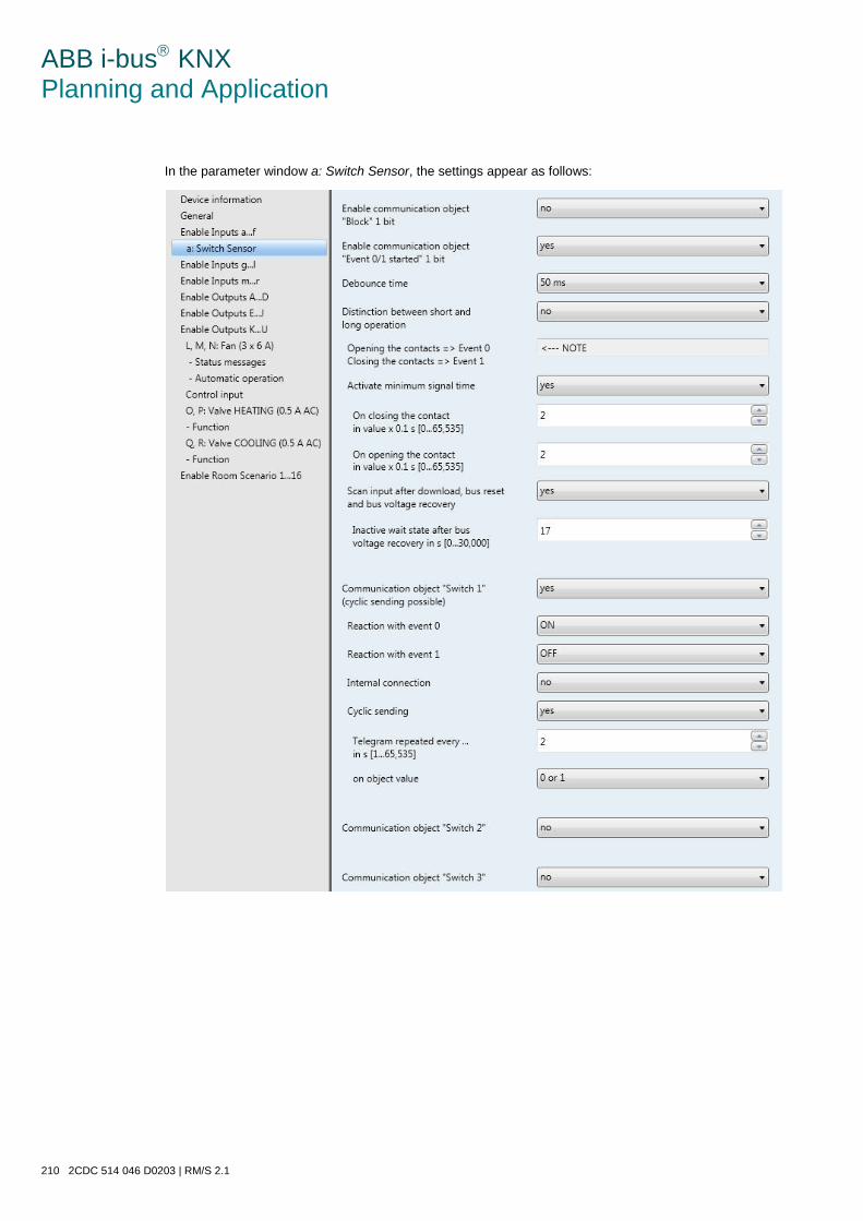
ABB i-bus KNX Planning and Application
210 2CDC 514 046 D0203 | RM/S 2.1
In the parameter window a: Switch Sensor, the settings appear as follows:
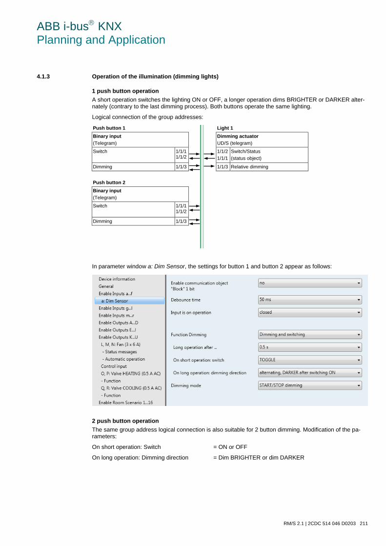
ABB i-bus KNX Planning and Application
RM/S 2.1 | 2CDC 514 046 D0203 211
4.1.3 Operation of the illumination (dimming lights)
1 push button operation A short operation switches the lighting ON or OFF, a longer operation dims BRIGHTER or DARKER alter-nately (contrary to the last dimming process). Both buttons operate the same lighting.
Logical connection of the group addresses:
Push button 1 Light 1 Binary input (Telegram)
Dimming actuator UD/S (telegram)
Switch 1/1/1 1/1/2
1/1/2 1/1/1
Switch/Status (status object)
Dimming 1/1/3 1/1/3 Relative dimming
Push button 2 Binary input (Telegram)
Switch 1/1/1 1/1/2
Dimming 1/1/3
In parameter window a: Dim Sensor, the settings for button 1 and button 2 appear as follows:
2 push button operation The same group address logical connection is also suitable for 2 button dimming. Modification of the pa-rameters:
On short operation: Switch = ON or OFF
On long operation: Dimming direction = Dim BRIGHTER or dim DARKER
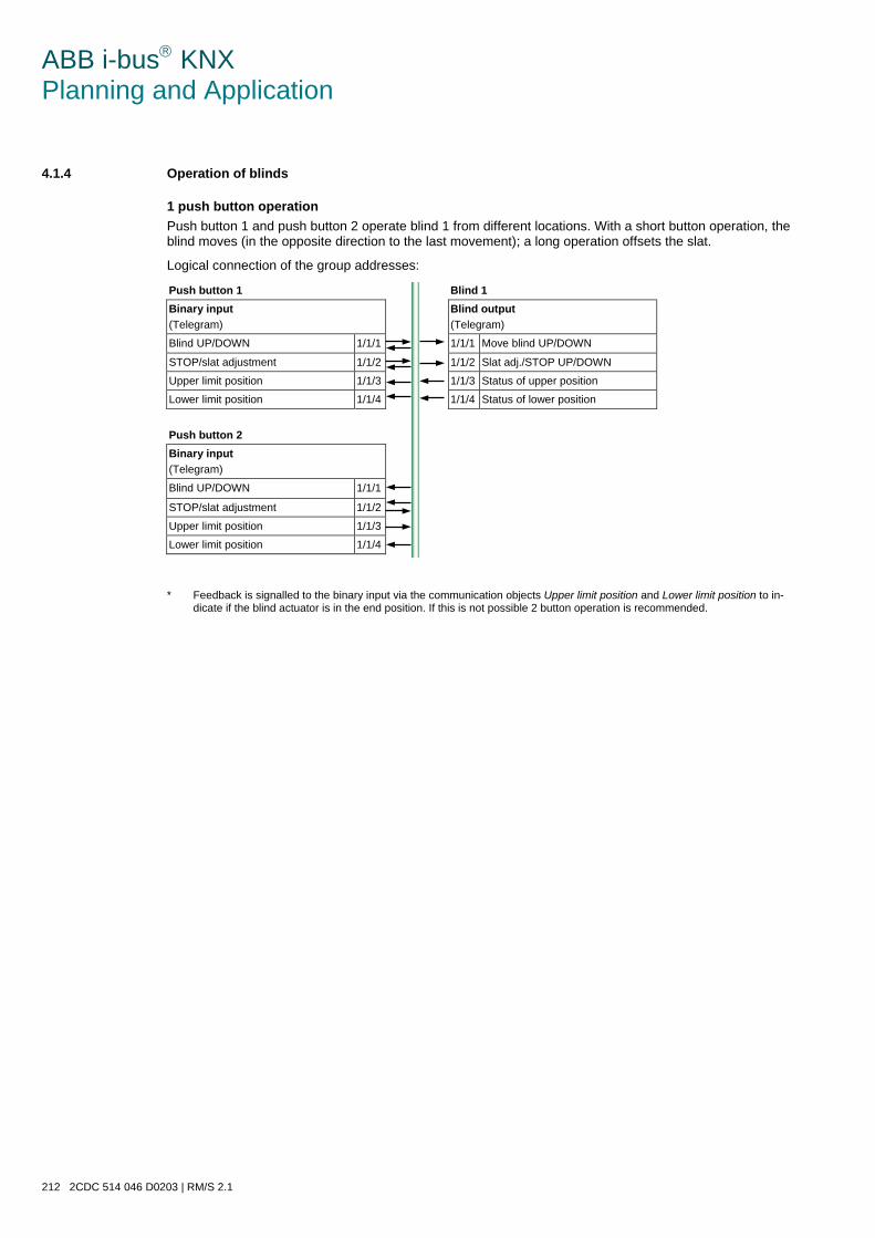
ABB i-bus KNX Planning and Application
212 2CDC 514 046 D0203 | RM/S 2.1
4.1.4 Operation of blinds
1 push button operation Push button 1 and push button 2 operate blind 1 from different locations. With a short button operation, the blind moves (in the opposite direction to the last movement); a long operation offsets the slat.
Logical connection of the group addresses:
Push button 1 Blind 1 Binary input (Telegram)
Blind output (Telegram)
Blind UP/DOWN 1/1/1 1/1/1 Move blind UP/DOWN
STOP/slat adjustment 1/1/2 1/1/2 Slat adj./STOP UP/DOWN
Upper limit position 1/1/3 1/1/3 Status of upper position
Lower limit position 1/1/4 1/1/4 Status of lower position
Push button 2 Binary input (Telegram)
Blind UP/DOWN 1/1/1 STOP/slat adjustment 1/1/2 Upper limit position 1/1/3 Lower limit position 1/1/4 * Feedback is signalled to the binary input via the communication objects Upper limit position and Lower limit position to in-
dicate if the blind actuator is in the end position. If this is not possible 2 button operation is recommended.
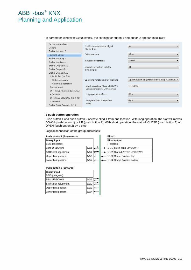
ABB i-bus KNX Planning and Application
RM/S 2.1 | 2CDC 514 046 D0203 213
In parameter window a: Blind sensor, the settings for button 1 and button 2 appear as follows:
2 push button operation Push button 1 and push button 2 operate blind 1 from one location. With long operation, the slat will moves DOWN (push button 1) or UP (push button 2). With short operation, the slat will CLOSE (push button 1) or OPEN (push button 2) by a step.
Logical connection of the group addresses:
Push button 1 (downwards) Blind 1 Binary input BE/S (telegram)
Blind output (Telegram)
Blind UP/DOWN 1/1/1 1/1/1 Move blind UP/DOWN
STOP/slat adjustment 1/1/2 1/1/2 Slat adj./STOP UP/DOWN
Upper limit position 1/1/3 1/1/3 Status Position top
Lower limit position 1/1/4 1/1/4 Status Position bottom
Push button 2 (upwards) Binary input BE/S (telegram)
Blind UP/DOWN 1/1/1 STOP/slat adjustment 1/1/2 Upper limit position 1/1/3 Lower limit position 1/1/4
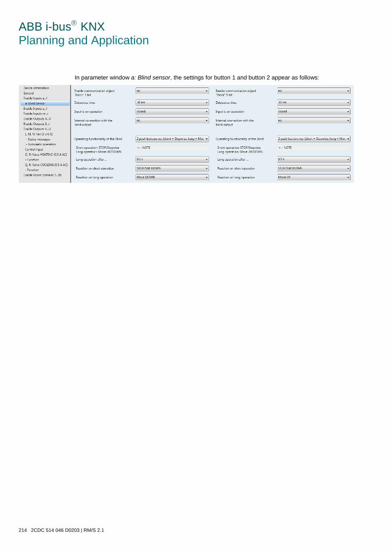
ABB i-bus KNX Planning and Application
214 2CDC 514 046 D0203 | RM/S 2.1
In parameter window a: Blind sensor, the settings for button 1 and button 2 appear as follows:
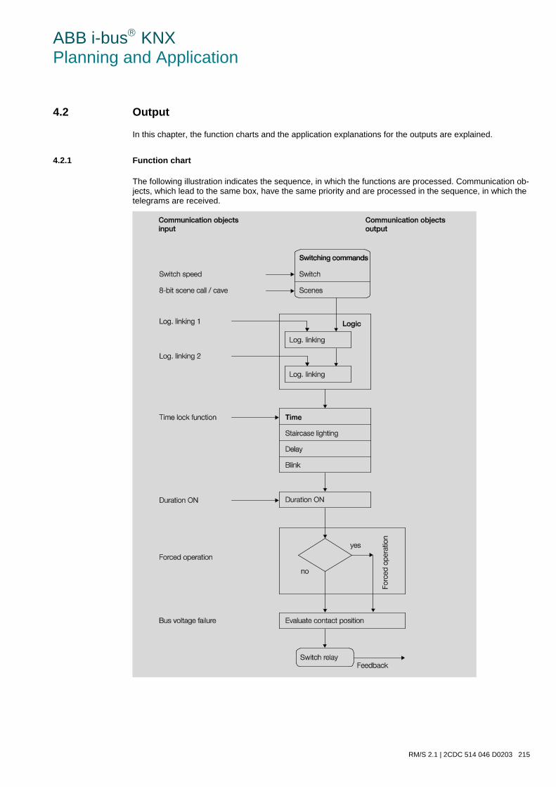
ABB i-bus KNX Planning and Application
RM/S 2.1 | 2CDC 514 046 D0203 215
4.2 Output
In this chapter, the function charts and the application explanations for the outputs are explained.
4.2.1 Function chart
The following illustration indicates the sequence, in which the functions are processed. Communication ob-jects, which lead to the same box, have the same priority and are processed in the sequence, in which the telegrams are received.
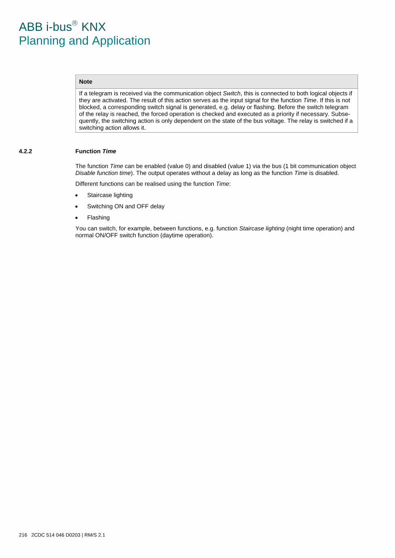
ABB i-bus KNX Planning and Application
216 2CDC 514 046 D0203 | RM/S 2.1
Note
If a telegram is received via the communication object Switch, this is connected to both logical objects if they are activated. The result of this action serves as the input signal for the function Time. If this is not blocked, a corresponding switch signal is generated, e.g. delay or flashing. Before the switch telegram of the relay is reached, the forced operation is checked and executed as a priority if necessary. Subse-quently, the switching action is only dependent on the state of the bus voltage. The relay is switched if a switching action allows it.
4.2.2 Function Time
The function Time can be enabled (value 0) and disabled (value 1) via the bus (1 bit communication object Disable function time). The output operates without a delay as long as the function Time is disabled.
Different functions can be realised using the function Time:
• Staircase lighting
• Switching ON and OFF delay
• Flashing
You can switch, for example, between functions, e.g. function Staircase lighting (night time operation) and normal ON/OFF switch function (daytime operation).
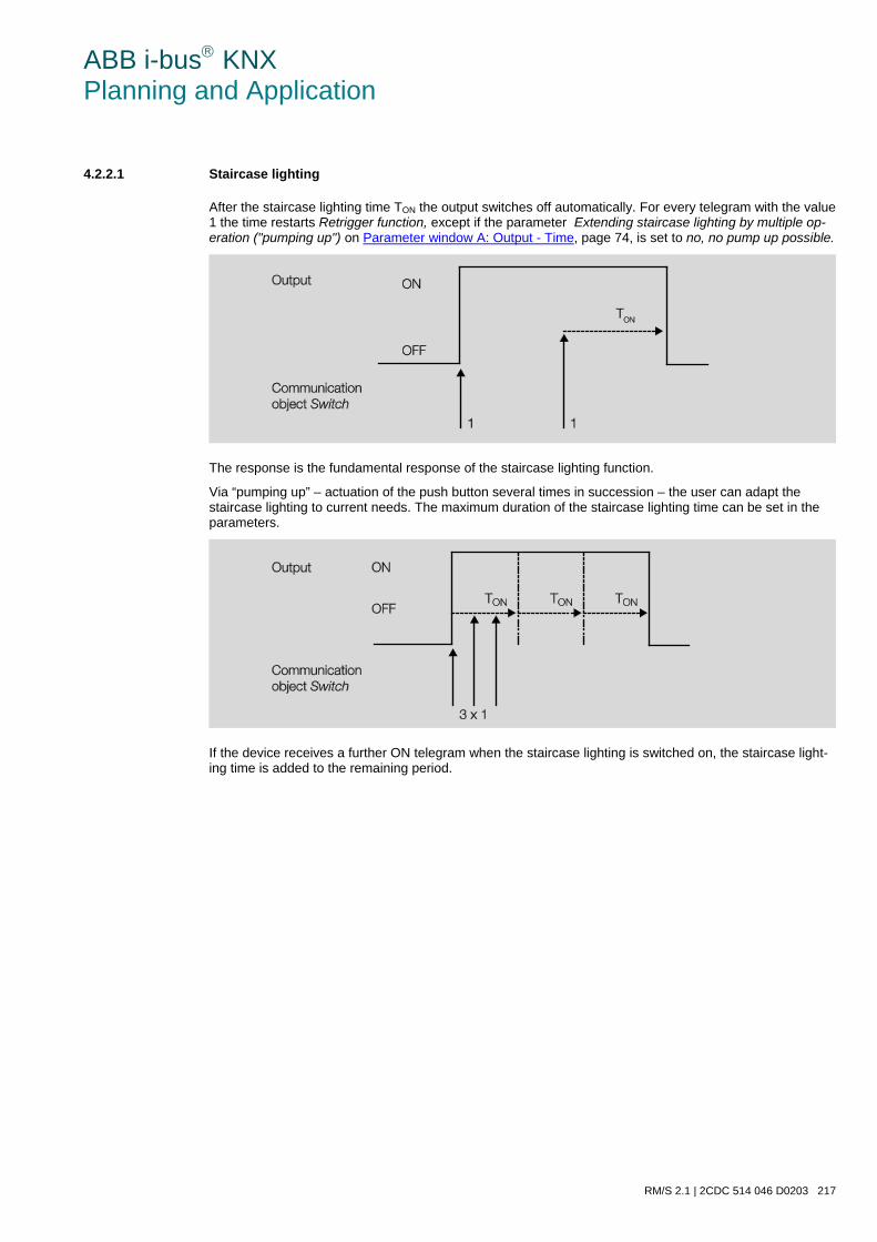
ABB i-bus KNX Planning and Application
RM/S 2.1 | 2CDC 514 046 D0203 217
4.2.2.1 Staircase lighting
After the staircase lighting time TON the output switches off automatically. For every telegram with the value 1 the time restarts Retrigger function, except if the parameter Extending staircase lighting by multiple op-eration ("pumping up") on Parameter window A: Output - Time, page 74, is set to no, no pump up possible.
The response is the fundamental response of the staircase lighting function.
Via “pumping up” – actuation of the push button several times in succession – the user can adapt the staircase lighting to current needs. The maximum duration of the staircase lighting time can be set in the parameters.
If the device receives a further ON telegram when the staircase lighting is switched on, the staircase light-ing time is added to the remaining period.
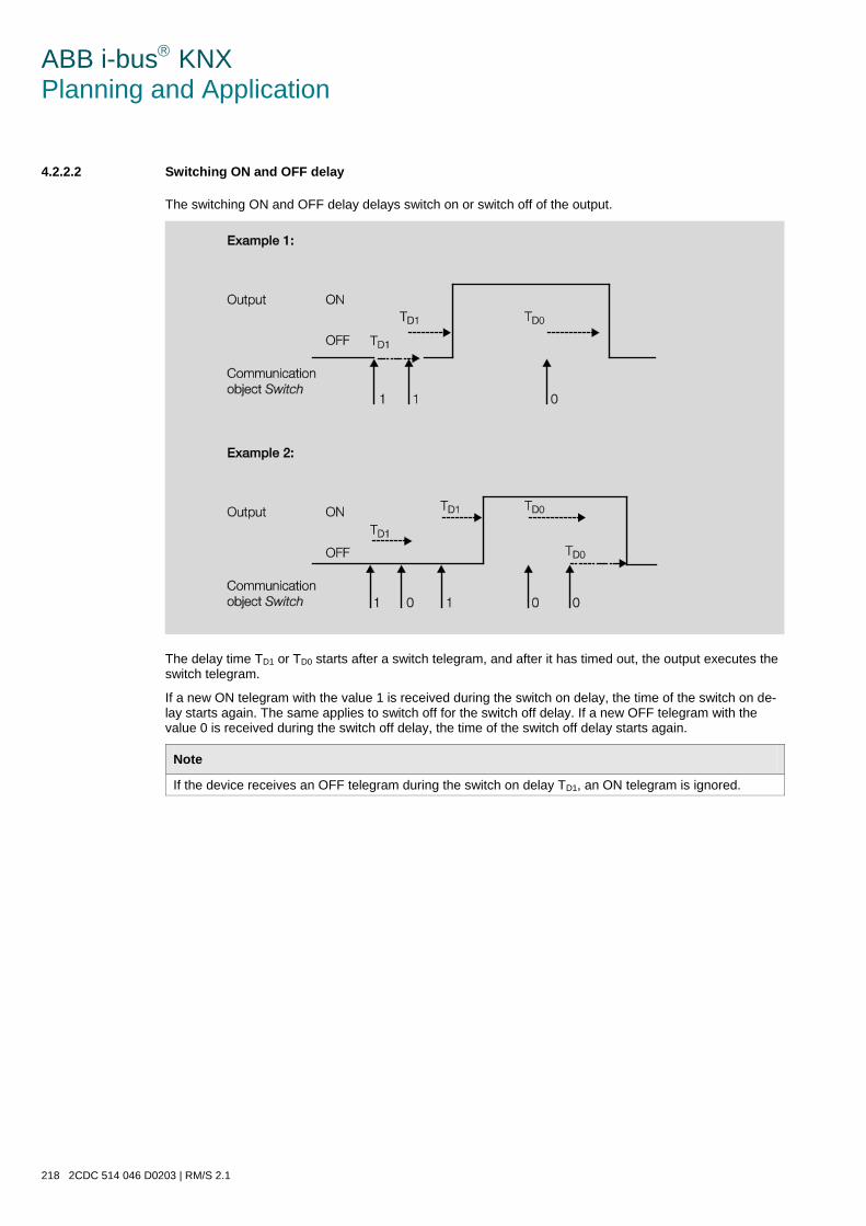
ABB i-bus KNX Planning and Application
218 2CDC 514 046 D0203 | RM/S 2.1
4.2.2.2 Switching ON and OFF delay
The switching ON and OFF delay delays switch on or switch off of the output.
The delay time TD1 or TD0 starts after a switch telegram, and after it has timed out, the output executes the switch telegram.
If a new ON telegram with the value 1 is received during the switch on delay, the time of the switch on de-lay starts again. The same applies to switch off for the switch off delay. If a new OFF telegram with the value 0 is received during the switch off delay, the time of the switch off delay starts again.
Note
If the device receives an OFF telegram during the switch on delay TD1, an ON telegram is ignored.
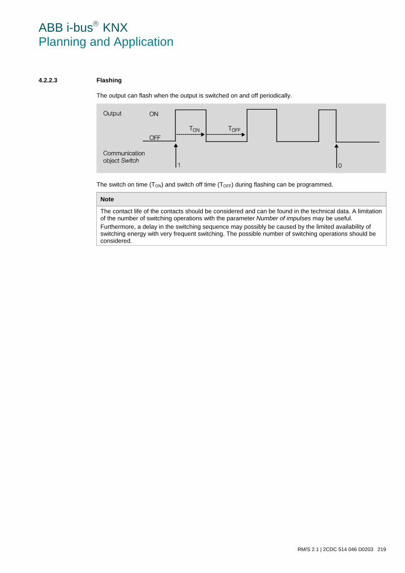
ABB i-bus KNX Planning and Application
RM/S 2.1 | 2CDC 514 046 D0203 219
4.2.2.3 Flashing
The output can flash when the output is switched on and off periodically.
The switch on time (TON) and switch off time (TOFF) during flashing can be programmed.
Note
The contact life of the contacts should be considered and can be found in the technical data. A limitation of the number of switching operations with the parameter Number of impulses may be useful. Furthermore, a delay in the switching sequence may possibly be caused by the limited availability of switching energy with very frequent switching. The possible number of switching operations should be considered.
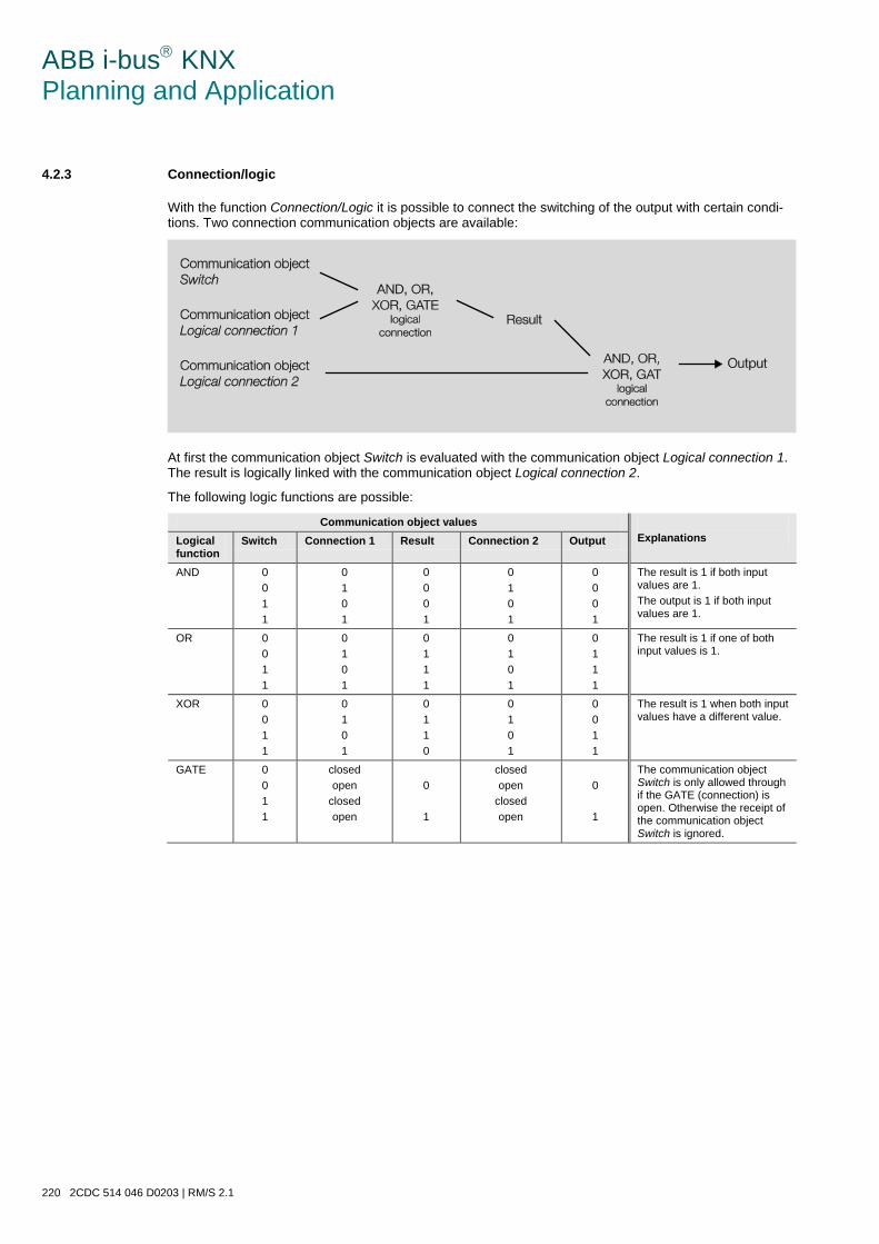
ABB i-bus KNX Planning and Application
220 2CDC 514 046 D0203 | RM/S 2.1
4.2.3 Connection/logic
With the function Connection/Logic it is possible to connect the switching of the output with certain condi-tions. Two connection communication objects are available:
At first the communication object Switch is evaluated with the communication object Logical connection 1. The result is logically linked with the communication object Logical connection 2.
The following logic functions are possible:
Communication object values Explanations Logical
function Switch Connection 1 Result Connection 2 Output
AND 0 0 1 1
0 1 0 1
0 0 0 1
0 1 0 1
0 0 0 1
The result is 1 if both input values are 1. The output is 1 if both input values are 1.
OR 0 0 1 1
0 1 0 1
0 1 1 1
0 1 0 1
0 1 1 1
The result is 1 if one of both input values is 1.
XOR 0 0 1 1
0 1 0 1
0 1 1 0
0 1 0 1
0 0 1 1
The result is 1 when both input values have a different value.
GATE 0 0 1 1
closed open
closed open
0
1
closed open
closed open
0
1
The communication object Switch is only allowed through if the GATE (connection) is open. Otherwise the receipt of the communication object Switch is ignored.
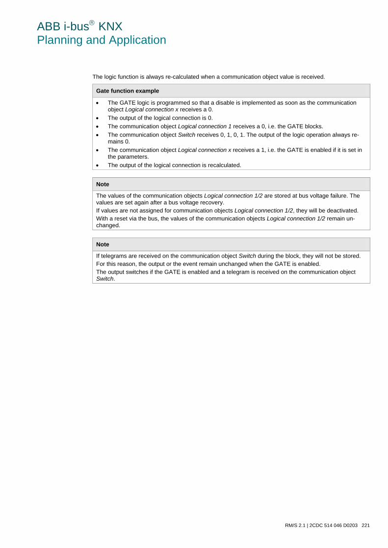
ABB i-bus KNX Planning and Application
RM/S 2.1 | 2CDC 514 046 D0203 221
The logic function is always re-calculated when a communication object value is received.
Gate function example
• The GATE logic is programmed so that a disable is implemented as soon as the communication object Logical connection x receives a 0.
• The output of the logical connection is 0. • The communication object Logical connection 1 receives a 0, i.e. the GATE blocks. • The communication object Switch receives 0, 1, 0, 1. The output of the logic operation always re-
mains 0. • The communication object Logical connection x receives a 1, i.e. the GATE is enabled if it is set in
the parameters. • The output of the logical connection is recalculated.
Note
The values of the communication objects Logical connection 1/2 are stored at bus voltage failure. The values are set again after a bus voltage recovery. If values are not assigned for communication objects Logical connection 1/2, they will be deactivated. With a reset via the bus, the values of the communication objects Logical connection 1/2 remain un-changed.
Note
If telegrams are received on the communication object Switch during the block, they will not be stored. For this reason, the output or the event remain unchanged when the GATE is enabled. The output switches if the GATE is enabled and a telegram is received on the communication object Switch.

ABB i-bus KNX Planning and Application
222 2CDC 514 046 D0203 | RM/S 2.1
4.2.4 Function Scene
With the scene using 8 bits, the push button issues the Room Master with the instruction to call a scene. The scene is not stored in the push button but rather in the Room Master.
A scene number is sent with the telegram value which must correspond with the scene number in the pa-rameters of the Room Master.
Up to 64 different scenes are managed via a single group address. The scene telegram contains the call or store functions of a scene.
In the following, the scene function is described which controls multiple KNX devices.
With the scene it is possible to retrieve one of 64 scenes or to connect multiple KNX devices in a scene. The scene can be retrieved or stored using a single telegram. It is a prerequisite that all the operating de-vices are parameterized with the same scene number.
Each KNX device involved receives the scene telegram and independently controls the scenes values. Us-ing the Room Master, for example, the outputs are switched on or off, the blind moves to a determine posi-tion.
Up to 64 different scenes can be managed via a single KNX group address. The following information is contained in a scene telegram:
• Number of the scene (1…64)
• Call scene / store scene For further information see: Code table scene (8 bit), page 320
Benefits
The function Scene with ABB i-bus® devices offers the following decisive advantage: All settings to be undertaken in a scene are stored in the device. Therefore, they must not be sent via the KNX when a scene is called, and only a figure value which has been assigned to this scene is nec-essary. This considerably reduces the load on the bus and prevents unnecessary telegram traffic on the KNX.
Note
The scene numbering 1…64 is retrieved via the KNX with a telegram number 0 to 63. For correspond-ing scene coding see Code table scene (8 bit), page 320.
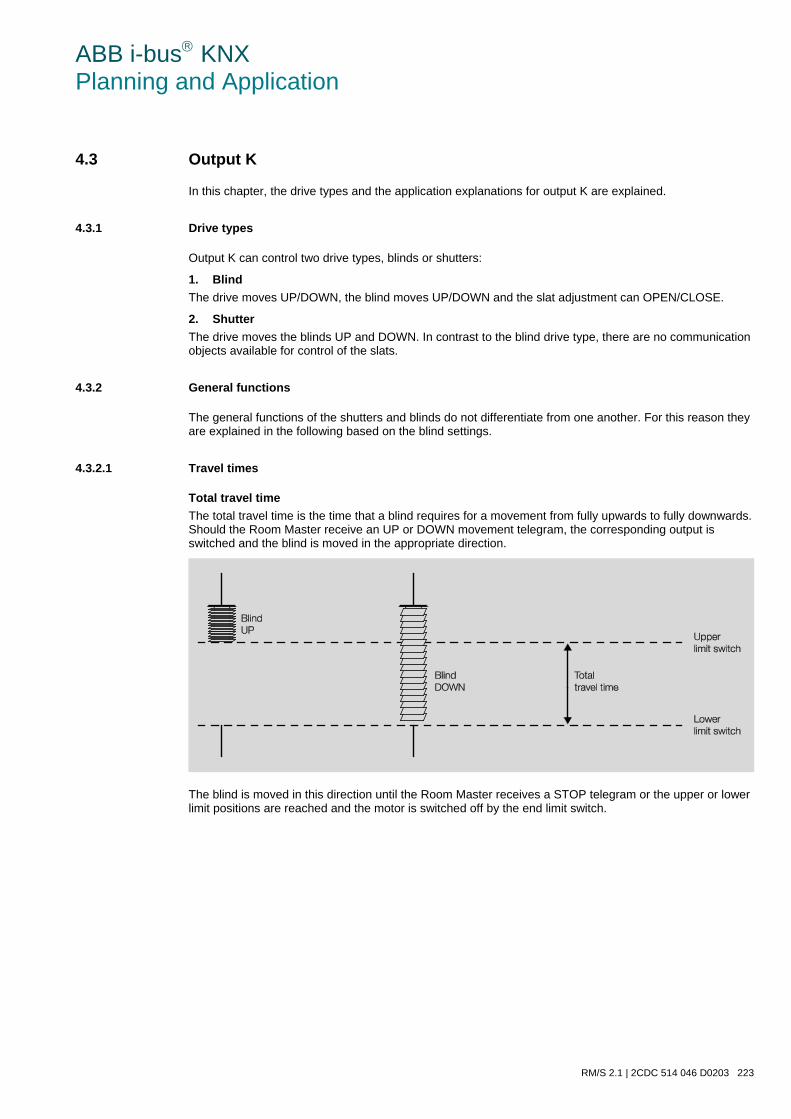
ABB i-bus KNX Planning and Application
RM/S 2.1 | 2CDC 514 046 D0203 223
4.3 Output K
In this chapter, the drive types and the application explanations for output K are explained.
4.3.1 Drive types
Output K can control two drive types, blinds or shutters:
1. Blind The drive moves UP/DOWN, the blind moves UP/DOWN and the slat adjustment can OPEN/CLOSE.
2. Shutter The drive moves the blinds UP and DOWN. In contrast to the blind drive type, there are no communication objects available for control of the slats.
4.3.2 General functions
The general functions of the shutters and blinds do not differentiate from one another. For this reason they are explained in the following based on the blind settings.
4.3.2.1 Travel times
Total travel time The total travel time is the time that a blind requires for a movement from fully upwards to fully downwards. Should the Room Master receive an UP or DOWN movement telegram, the corresponding output is switched and the blind is moved in the appropriate direction.
The blind is moved in this direction until the Room Master receives a STOP telegram or the upper or lower limit positions are reached and the motor is switched off by the end limit switch.
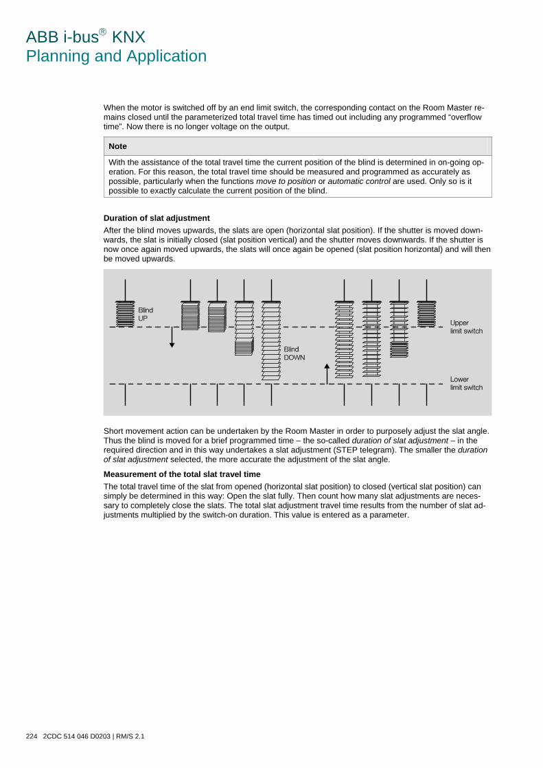
ABB i-bus KNX Planning and Application
224 2CDC 514 046 D0203 | RM/S 2.1
When the motor is switched off by an end limit switch, the corresponding contact on the Room Master re-mains closed until the parameterized total travel time has timed out including any programmed “overflow time”. Now there is no longer voltage on the output.
Note
With the assistance of the total travel time the current position of the blind is determined in on-going op-eration. For this reason, the total travel time should be measured and programmed as accurately as possible, particularly when the functions move to position or automatic control are used. Only so is it possible to exactly calculate the current position of the blind.
Duration of slat adjustment After the blind moves upwards, the slats are open (horizontal slat position). If the shutter is moved down-wards, the slat is initially closed (slat position vertical) and the shutter moves downwards. If the shutter is now once again moved upwards, the slats will once again be opened (slat position horizontal) and will then be moved upwards.
Short movement action can be undertaken by the Room Master in order to purposely adjust the slat angle. Thus the blind is moved for a brief programmed time – the so-called duration of slat adjustment – in the required direction and in this way undertakes a slat adjustment (STEP telegram). The smaller the duration of slat adjustment selected, the more accurate the adjustment of the slat angle.
Measurement of the total slat travel time The total travel time of the slat from opened (horizontal slat position) to closed (vertical slat position) can simply be determined in this way: Open the slat fully. Then count how many slat adjustments are neces-sary to completely close the slats. The total slat adjustment travel time results from the number of slat ad-justments multiplied by the switch-on duration. This value is entered as a parameter.
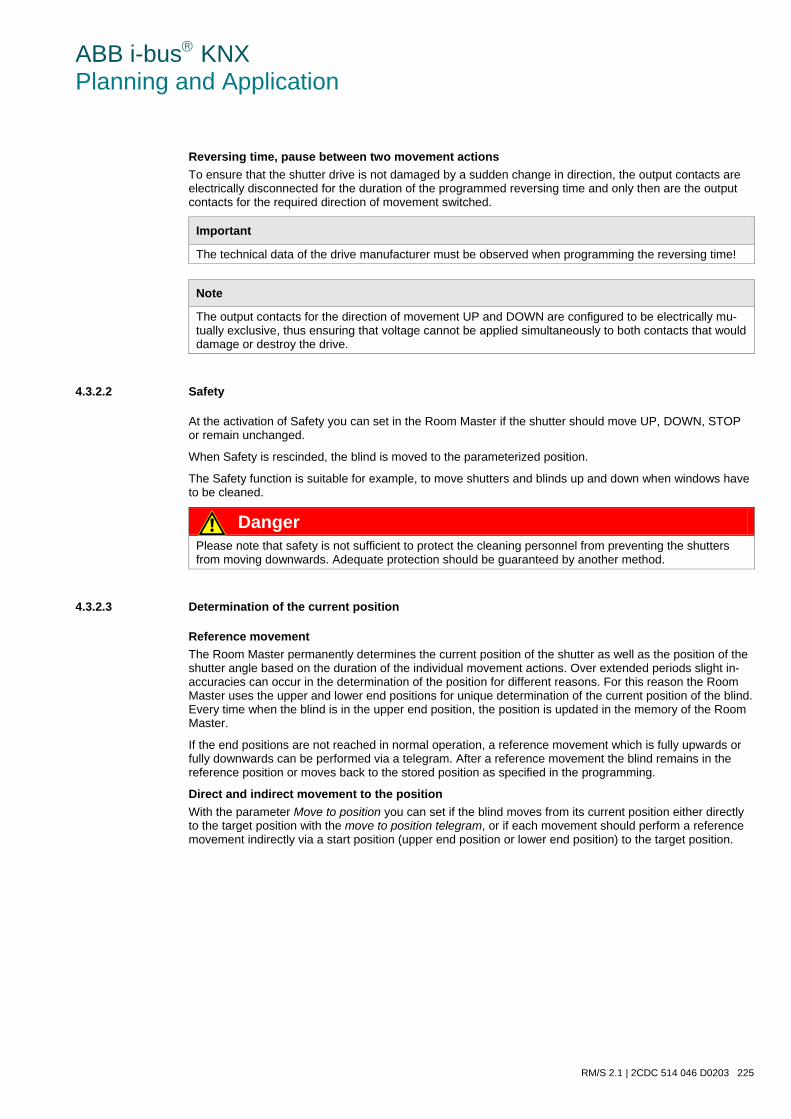
ABB i-bus KNX Planning and Application
RM/S 2.1 | 2CDC 514 046 D0203 225
Reversing time, pause between two movement actions To ensure that the shutter drive is not damaged by a sudden change in direction, the output contacts are electrically disconnected for the duration of the programmed reversing time and only then are the output contacts for the required direction of movement switched.
Important
The technical data of the drive manufacturer must be observed when programming the reversing time!
Note
The output contacts for the direction of movement UP and DOWN are configured to be electrically mu-tually exclusive, thus ensuring that voltage cannot be applied simultaneously to both contacts that would damage or destroy the drive.
4.3.2.2 Safety
At the activation of Safety you can set in the Room Master if the shutter should move UP, DOWN, STOP or remain unchanged.
When Safety is rescinded, the blind is moved to the parameterized position.
The Safety function is suitable for example, to move shutters and blinds up and down when windows have to be cleaned.
Danger Please note that safety is not sufficient to protect the cleaning personnel from preventing the shutters from moving downwards. Adequate protection should be guaranteed by another method.
4.3.2.3 Determination of the current position
Reference movement The Room Master permanently determines the current position of the shutter as well as the position of the shutter angle based on the duration of the individual movement actions. Over extended periods slight in-accuracies can occur in the determination of the position for different reasons. For this reason the Room Master uses the upper and lower end positions for unique determination of the current position of the blind. Every time when the blind is in the upper end position, the position is updated in the memory of the Room Master.
If the end positions are not reached in normal operation, a reference movement which is fully upwards or fully downwards can be performed via a telegram. After a reference movement the blind remains in the reference position or moves back to the stored position as specified in the programming.
Direct and indirect movement to the position With the parameter Move to position you can set if the blind moves from its current position either directly to the target position with the move to position telegram, or if each movement should perform a reference movement indirectly via a start position (upper end position or lower end position) to the target position.
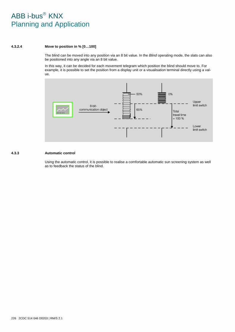
ABB i-bus KNX Planning and Application
226 2CDC 514 046 D0203 | RM/S 2.1
4.3.2.4 Move to position in % [0…100]
The blind can be moved into any position via an 8 bit value. In the Blind operating mode, the slats can also be positioned into any angle via an 8 bit value.
In this way, it can be decided for each movement telegram which position the blind should move to. For example, it is possible to set the position from a display unit or a visualisation terminal directly using a val-ue.
4.3.3 Automatic control
Using the automatic control, it is possible to realise a comfortable automatic sun screening system as well as to feedback the status of the blind.
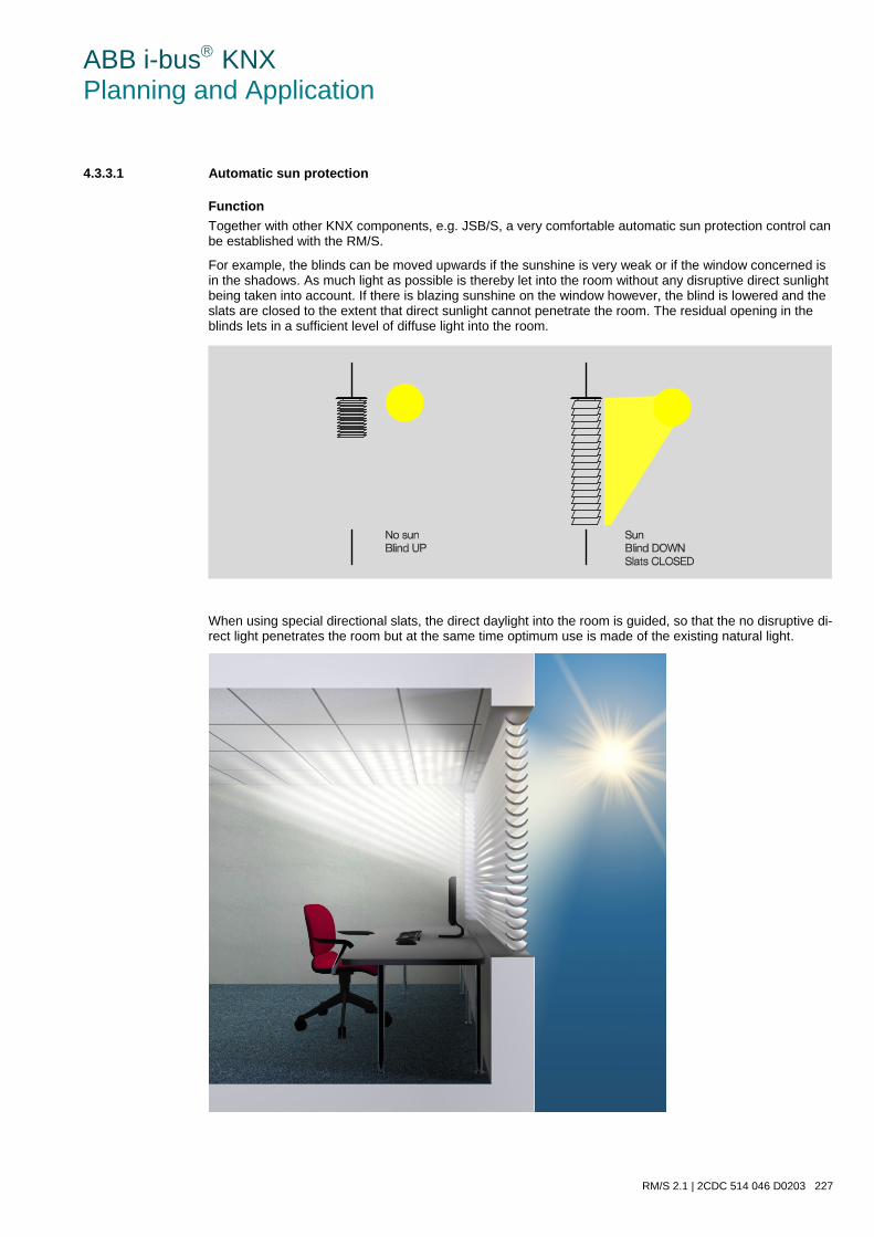
ABB i-bus KNX Planning and Application
RM/S 2.1 | 2CDC 514 046 D0203 227
4.3.3.1 Automatic sun protection
Function Together with other KNX components, e.g. JSB/S, a very comfortable automatic sun protection control can be established with the RM/S.
For example, the blinds can be moved upwards if the sunshine is very weak or if the window concerned is in the shadows. As much light as possible is thereby let into the room without any disruptive direct sunlight being taken into account. If there is blazing sunshine on the window however, the blind is lowered and the slats are closed to the extent that direct sunlight cannot penetrate the room. The residual opening in the blinds lets in a sufficient level of diffuse light into the room.
When using special directional slats, the direct daylight into the room is guided, so that the no disruptive di-rect light penetrates the room but at the same time optimum use is made of the existing natural light.
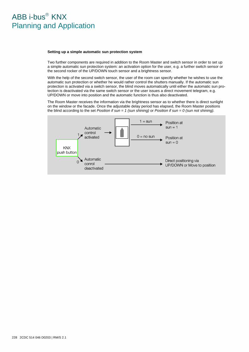
ABB i-bus KNX Planning and Application
228 2CDC 514 046 D0203 | RM/S 2.1
Setting up a simple automatic sun protection system
Two further components are required in addition to the Room Master and switch sensor in order to set up a simple automatic sun protection system: an activation option for the user, e.g. a further switch sensor or the second rocker of the UP/DOWN touch sensor and a brightness sensor.
With the help of the second switch sensor, the user of the room can specify whether he wishes to use the automatic sun protection or whether he would rather control the shutters manually. If the automatic sun protection is activated via a switch sensor, the blind moves automatically until either the automatic sun pro-tection is deactivated via the same switch sensor or the user issues a direct movement telegram, e.g. UP/DOWN or move into position and the automatic function is thus also deactivated.
The Room Master receives the information via the brightness sensor as to whether there is direct sunlight on the window or the facade. Once the adjustable delay period has elapsed, the Room Master positions the blind according to the set Position if sun = 1 (sun shining) or Position if sun = 0 (sun not shining).
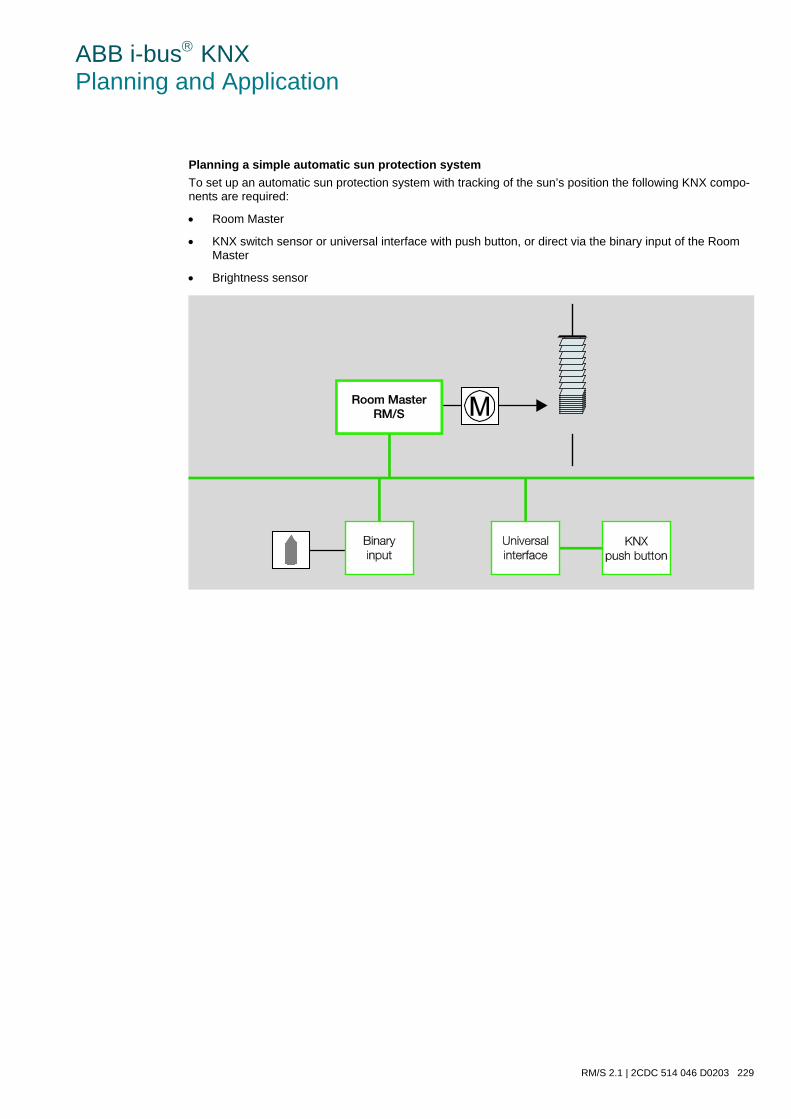
ABB i-bus KNX Planning and Application
RM/S 2.1 | 2CDC 514 046 D0203 229
Planning a simple automatic sun protection system To set up an automatic sun protection system with tracking of the sun’s position the following KNX compo-nents are required:
• Room Master
• KNX switch sensor or universal interface with push button, or direct via the binary input of the Room Master
• Brightness sensor

ABB i-bus KNX Planning and Application
230 2CDC 514 046 D0203 | RM/S 2.1
Design of an automatic sun protection system with tracking of the sun’s position To set up an automatic sun protection system with tracking of the sun’s position, an additional Shutter Control Unit JSB/S 1.1 is required.
The current position of the sun is continually calculated in the shutter control unit. The blind is moved via an 8 bit value into the optimum position to deflect direct sunshine but to let through as much diffuse light as possible. The influence of shadows e.g. the buildings opposite can also be taken into account in the shut-ter control unit.
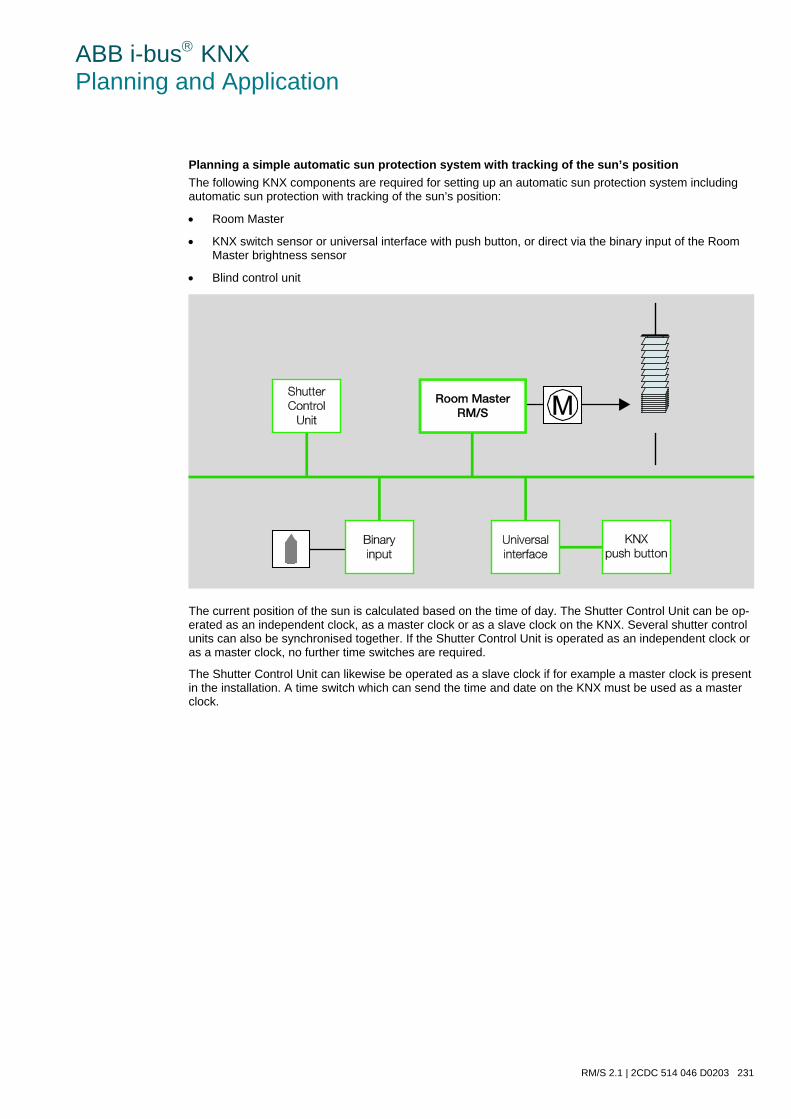
ABB i-bus KNX Planning and Application
RM/S 2.1 | 2CDC 514 046 D0203 231
Planning a simple automatic sun protection system with tracking of the sun’s position The following KNX components are required for setting up an automatic sun protection system including automatic sun protection with tracking of the sun’s position:
• Room Master
• KNX switch sensor or universal interface with push button, or direct via the binary input of the Room Master brightness sensor
• Blind control unit
The current position of the sun is calculated based on the time of day. The Shutter Control Unit can be op-erated as an independent clock, as a master clock or as a slave clock on the KNX. Several shutter control units can also be synchronised together. If the Shutter Control Unit is operated as an independent clock or as a master clock, no further time switches are required.
The Shutter Control Unit can likewise be operated as a slave clock if for example a master clock is present in the installation. A time switch which can send the time and date on the KNX must be used as a master clock.

ABB i-bus KNX Planning and Application
232 2CDC 514 046 D0203 | RM/S 2.1
4.3.3.2 Status feedback
Position in [0…100] The Room Master can feedback the position of the blind on the bus as an 8 bit value via the same com-munication object used to call the position. The corresponding group address should be defined in the ETS as the “sending group address”.
ABB i-bus KNX Planning and Application
RM/S 2.1 | 2CDC 514 046 D0203 233
4.4 Heating, ventilation, climate control with Fan Coil units
The Room Master RM/S controls single-phase fans, blowers or Fan Coil units. Three speed single phase fans with step or changeover control are possible.
Special fan properties such as switchover pauses, dwell times and a start-up phase can be parameterized. Up to two input variables for heating and cooling signals, e.g. for a thermostat, are available.
The separate fan and valve parameterization in the RM/S provides a maximum in flexibility and very many combination possibilities for various applications in the heating, ventilation and air-conditioning (HVAC) field.
4.4.1 Terms
Fan Coil unit is a term used for a fan convector or blower convection unit.
The Fan Coil unit is connected to a central heating and cooling water supply and generates the desired temperature for the room. A room can be heated, cooled and ventilated using a Fan Coil unit.
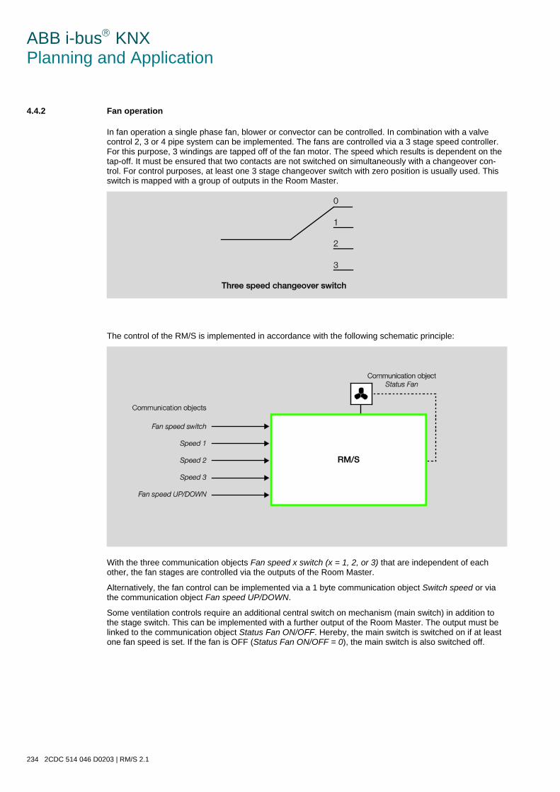
ABB i-bus KNX Planning and Application
234 2CDC 514 046 D0203 | RM/S 2.1
4.4.2 Fan operation
In fan operation a single phase fan, blower or convector can be controlled. In combination with a valve control 2, 3 or 4 pipe system can be implemented. The fans are controlled via a 3 stage speed controller. For this purpose, 3 windings are tapped off of the fan motor. The speed which results is dependent on the tap-off. It must be ensured that two contacts are not switched on simultaneously with a changeover con-trol. For control purposes, at least one 3 stage changeover switch with zero position is usually used. This switch is mapped with a group of outputs in the Room Master.
The control of the RM/S is implemented in accordance with the following schematic principle:
With the three communication objects Fan speed x switch (x = 1, 2, or 3) that are independent of each other, the fan stages are controlled via the outputs of the Room Master.
Alternatively, the fan control can be implemented via a 1 byte communication object Switch speed or via the communication object Fan speed UP/DOWN.
Some ventilation controls require an additional central switch on mechanism (main switch) in addition to the stage switch. This can be implemented with a further output of the Room Master. The output must be linked to the communication object Status Fan ON/OFF. Hereby, the main switch is switched on if at least one fan speed is set. If the fan is OFF (Status Fan ON/OFF = 0), the main switch is also switched off.
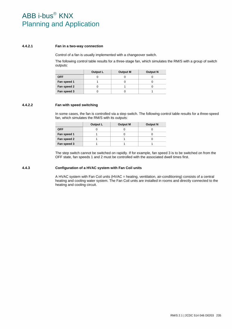
ABB i-bus KNX Planning and Application
RM/S 2.1 | 2CDC 514 046 D0203 235
4.4.2.1 Fan in a two-way connection
Control of a fan is usually implemented with a changeover switch.
The following control table results for a three-stage fan, which simulates the RM/S with a group of switch outputs:
Output L Output M Output N OFF 0 0 0 Fan speed 1 1 0 0 Fan speed 2 0 1 0 Fan speed 3 0 0 1
4.4.2.2 Fan with speed switching
In some cases, the fan is controlled via a step switch. The following control table results for a three-speed fan, which simulates the RM/S with its outputs:
Output L Output M Output N OFF 0 0 0 Fan speed 1 1 0 0 Fan speed 2 1 1 0 Fan speed 3 1 1 1
The step switch cannot be switched on rapidly. If for example, fan speed 3 is to be switched on from the OFF state, fan speeds 1 and 2 must be controlled with the associated dwell times first.
4.4.3 Configuration of a HVAC system with Fan Coil units
A HVAC system with Fan Coil units (HVAC = heating, ventilation, air-conditioning) consists of a central heating and cooling water system. The Fan Coil units are installed in rooms and directly connected to the heating and cooling circuit.
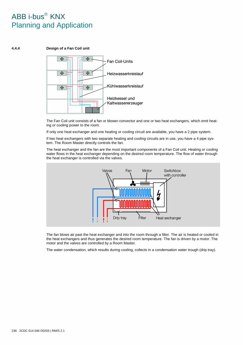
ABB i-bus KNX Planning and Application
236 2CDC 514 046 D0203 | RM/S 2.1
4.4.4 Design of a Fan Coil unit
The Fan Coil unit consists of a fan or blower-convector and one or two heat exchangers, which emit heat-ing or cooling power to the room.
If only one heat exchanger and one heating or cooling circuit are available, you have a 2 pipe system.
If two heat exchangers with two separate heating and cooling circuits are in use, you have a 4 pipe sys-tem. The Room Master directly controls the fan.
The heat exchanger and the fan are the most important components of a Fan Coil unit. Heating or cooling water flows in the heat exchanger depending on the desired room temperature. The flow of water through the heat exchanger is controlled via the valves.
The fan blows air past the heat exchanger and into the room through a filter. The air is heated or cooled in the heat exchangers and thus generates the desired room temperature. The fan is driven by a motor. The motor and the valves are controlled by a Room Master.
The water condensation, which results during cooling, collects in a condensation water trough (drip tray).
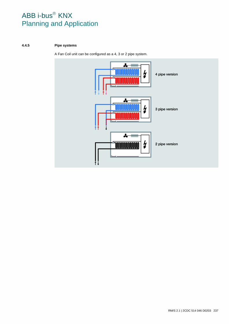
ABB i-bus KNX Planning and Application
RM/S 2.1 | 2CDC 514 046 D0203 237
4.4.5 Pipe systems
A Fan Coil unit can be configured as a 4, 3 or 2 pipe system.
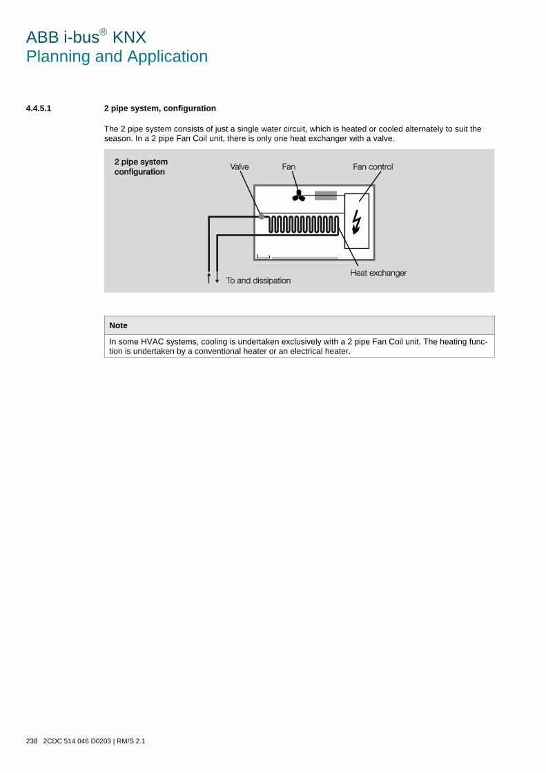
ABB i-bus KNX Planning and Application
238 2CDC 514 046 D0203 | RM/S 2.1
4.4.5.1 2 pipe system, configuration
The 2 pipe system consists of just a single water circuit, which is heated or cooled alternately to suit the season. In a 2 pipe Fan Coil unit, there is only one heat exchanger with a valve.
Note
In some HVAC systems, cooling is undertaken exclusively with a 2 pipe Fan Coil unit. The heating func-tion is undertaken by a conventional heater or an electrical heater.
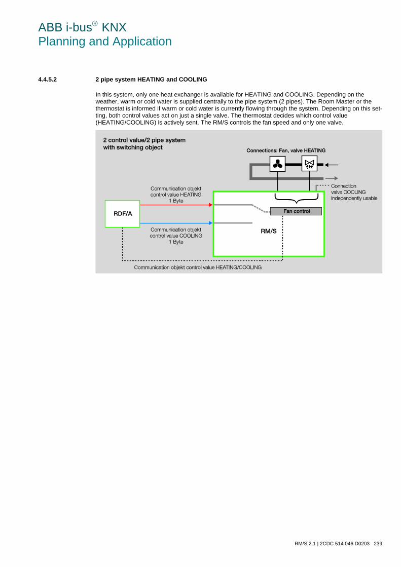
ABB i-bus KNX Planning and Application
RM/S 2.1 | 2CDC 514 046 D0203 239
4.4.5.2 2 pipe system HEATING and COOLING
In this system, only one heat exchanger is available for HEATING and COOLING. Depending on the weather, warm or cold water is supplied centrally to the pipe system (2 pipes). The Room Master or the thermostat is informed if warm or cold water is currently flowing through the system. Depending on this set-ting, both control values act on just a single valve. The thermostat decides which control value (HEATING/COOLING) is actively sent. The RM/S controls the fan speed and only one valve.
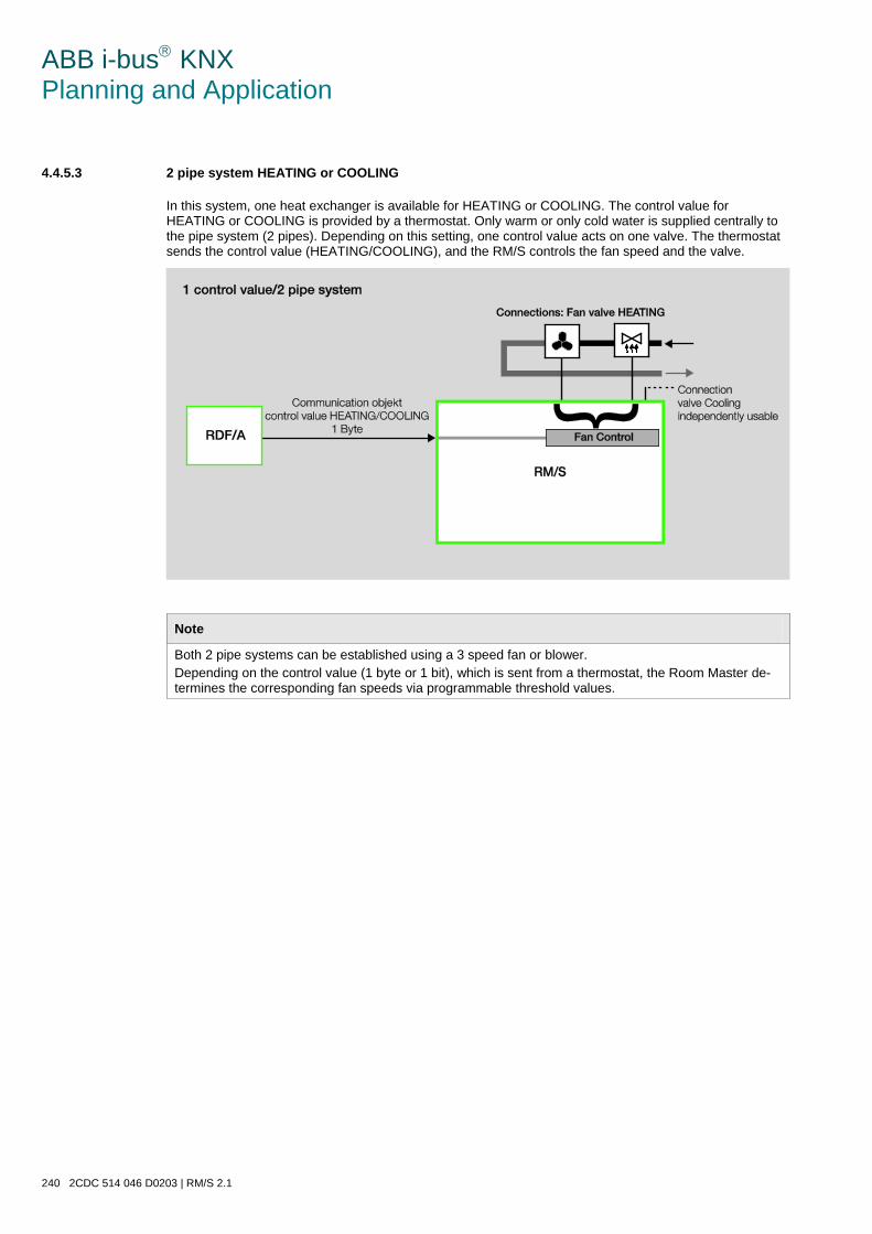
ABB i-bus KNX Planning and Application
240 2CDC 514 046 D0203 | RM/S 2.1
4.4.5.3 2 pipe system HEATING or COOLING
In this system, one heat exchanger is available for HEATING or COOLING. The control value for HEATING or COOLING is provided by a thermostat. Only warm or only cold water is supplied centrally to the pipe system (2 pipes). Depending on this setting, one control value acts on one valve. The thermostat sends the control value (HEATING/COOLING), and the RM/S controls the fan speed and the valve.
Note
Both 2 pipe systems can be established using a 3 speed fan or blower. Depending on the control value (1 byte or 1 bit), which is sent from a thermostat, the Room Master de-termines the corresponding fan speeds via programmable threshold values.
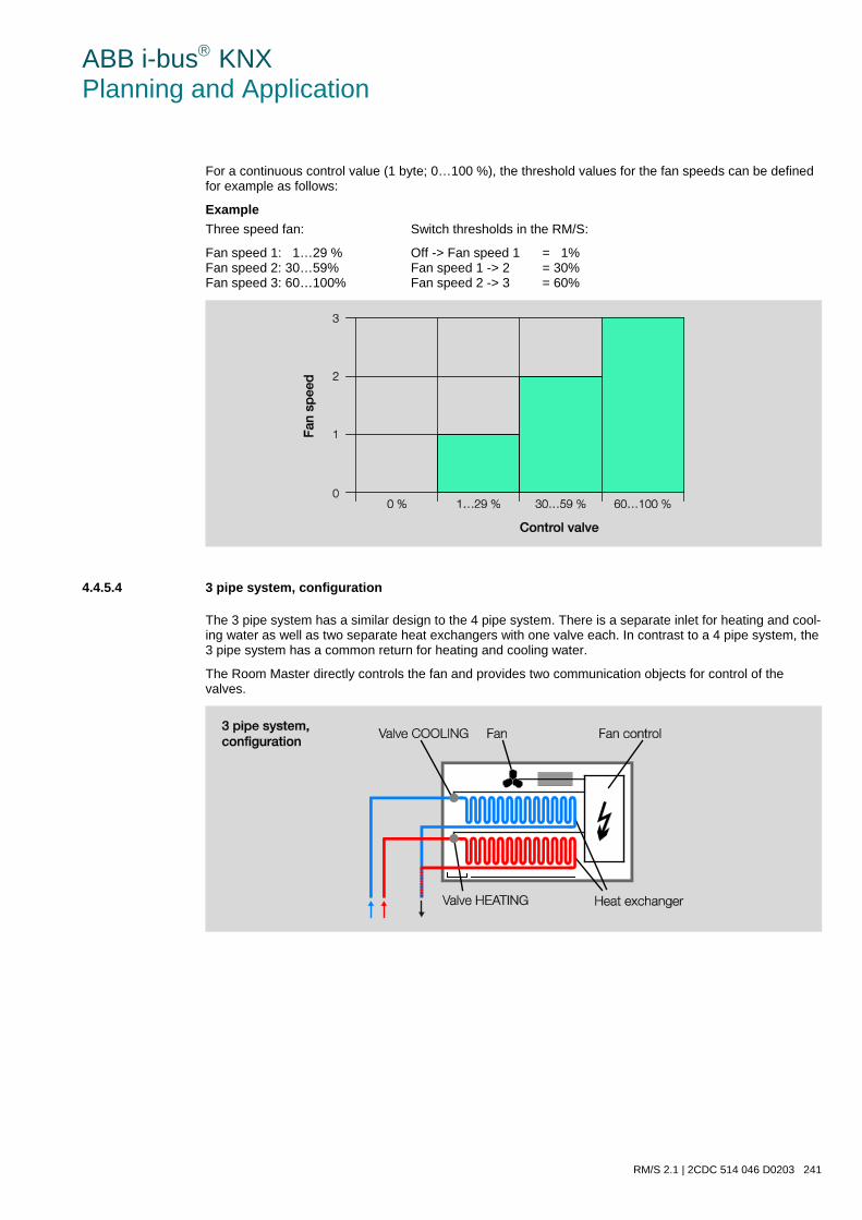
ABB i-bus KNX Planning and Application
RM/S 2.1 | 2CDC 514 046 D0203 241
For a continuous control value (1 byte; 0…100 %), the threshold values for the fan speeds can be defined for example as follows:
Example Three speed fan: Switch thresholds in the RM/S:
Fan speed 1: 1…29 % Off -> Fan speed 1 = 1% Fan speed 2: 30…59% Fan speed 1 -> 2 = 30% Fan speed 3: 60…100% Fan speed 2 -> 3 = 60%
4.4.5.4 3 pipe system, configuration
The 3 pipe system has a similar design to the 4 pipe system. There is a separate inlet for heating and cool-ing water as well as two separate heat exchangers with one valve each. In contrast to a 4 pipe system, the 3 pipe system has a common return for heating and cooling water.
The Room Master directly controls the fan and provides two communication objects for control of the valves.
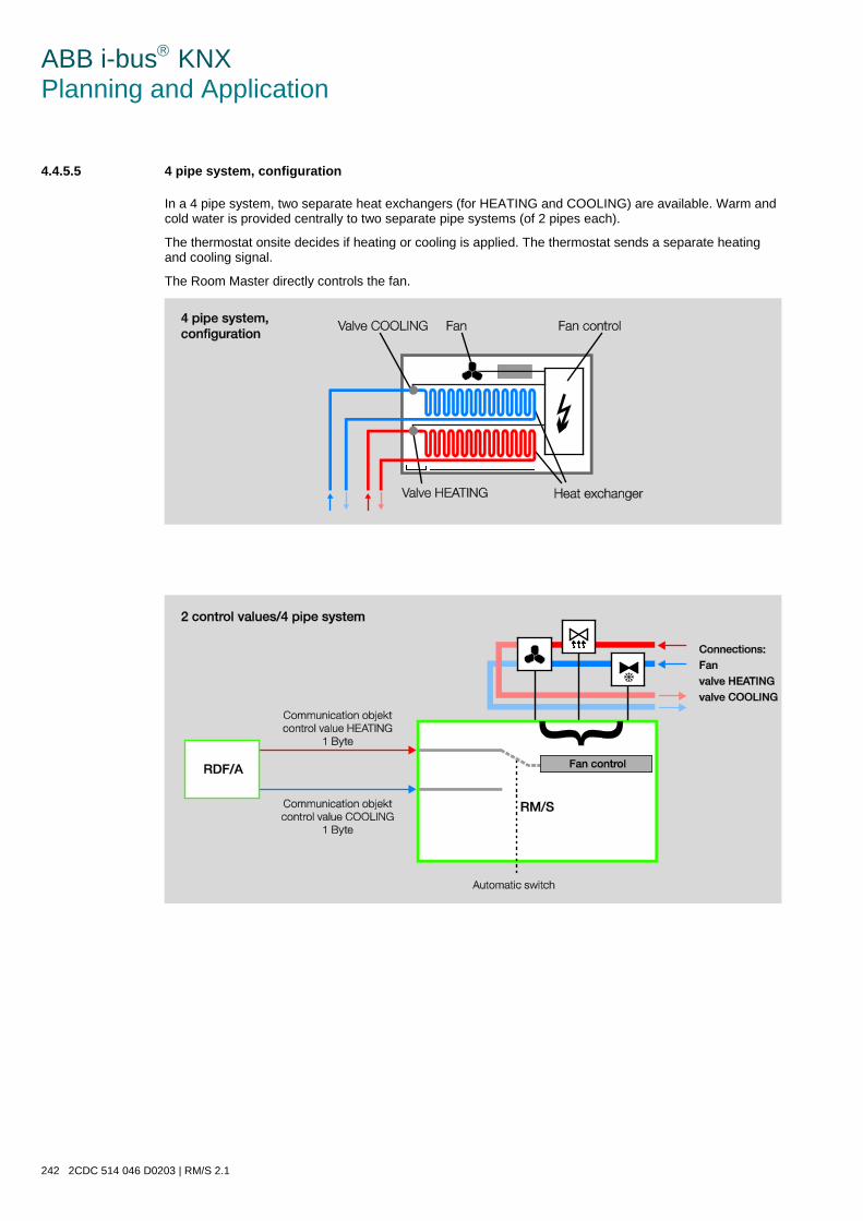
ABB i-bus KNX Planning and Application
242 2CDC 514 046 D0203 | RM/S 2.1
4.4.5.5 4 pipe system, configuration
In a 4 pipe system, two separate heat exchangers (for HEATING and COOLING) are available. Warm and cold water is provided centrally to two separate pipe systems (of 2 pipes each).
The thermostat onsite decides if heating or cooling is applied. The thermostat sends a separate heating and cooling signal.
The Room Master directly controls the fan.
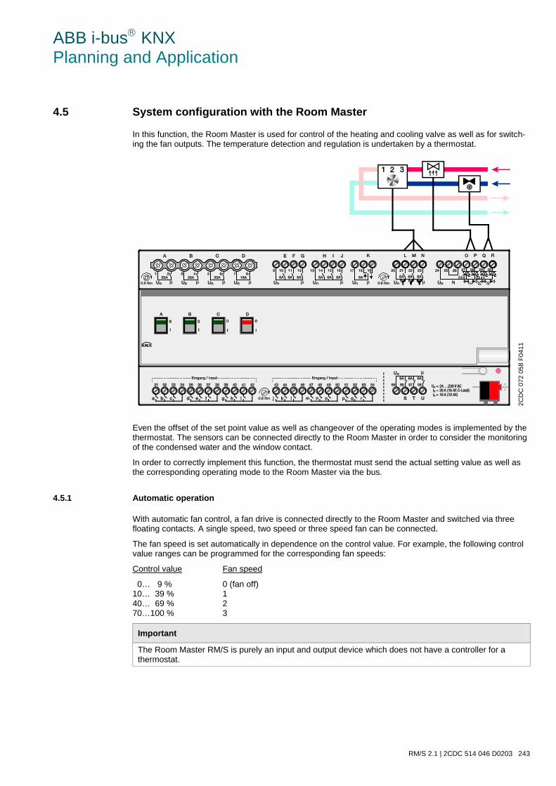
ABB i-bus KNX Planning and Application
RM/S 2.1 | 2CDC 514 046 D0203 243
4.5 System configuration with the Room Master
In this function, the Room Master is used for control of the heating and cooling valve as well as for switch-ing the fan outputs. The temperature detection and regulation is undertaken by a thermostat.
Even the offset of the set point value as well as changeover of the operating modes is implemented by the thermostat. The sensors can be connected directly to the Room Master in order to consider the monitoring of the condensed water and the window contact.
In order to correctly implement this function, the thermostat must send the actual setting value as well as the corresponding operating mode to the Room Master via the bus.
4.5.1 Automatic operation
With automatic fan control, a fan drive is connected directly to the Room Master and switched via three floating contacts. A single speed, two speed or three speed fan can be connected.
The fan speed is set automatically in dependence on the control value. For example, the following control value ranges can be programmed for the corresponding fan speeds:
Control value Fan speed
0… 9 % 0 (fan off) 10… 39 % 1 40… 69 % 2 70…100 % 3
Important
The Room Master RM/S is purely an input and output device which does not have a controller for a thermostat.
2CD
C 0
72 0
58 F
0411
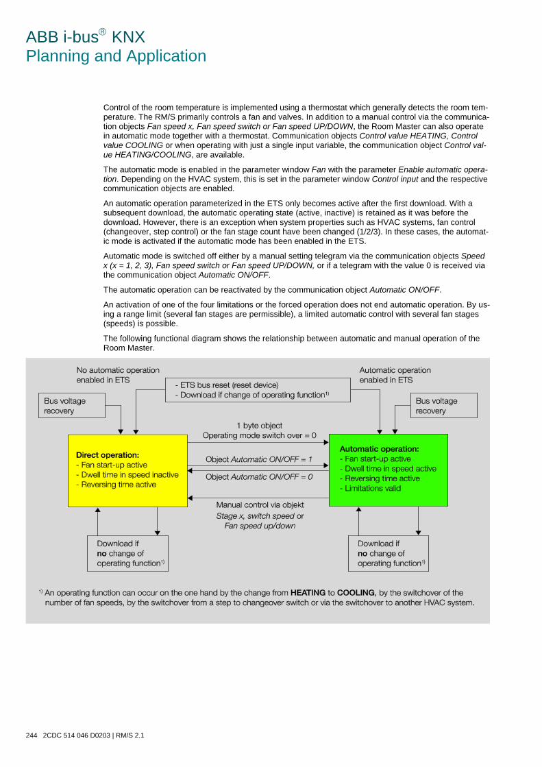
ABB i-bus KNX Planning and Application
244 2CDC 514 046 D0203 | RM/S 2.1
Control of the room temperature is implemented using a thermostat which generally detects the room tem-perature. The RM/S primarily controls a fan and valves. In addition to a manual control via the communica-tion objects Fan speed x, Fan speed switch or Fan speed UP/DOWN, the Room Master can also operate in automatic mode together with a thermostat. Communication objects Control value HEATING, Control value COOLING or when operating with just a single input variable, the communication object Control val-ue HEATING/COOLING, are available.
The automatic mode is enabled in the parameter window Fan with the parameter Enable automatic opera-tion. Depending on the HVAC system, this is set in the parameter window Control input and the respective communication objects are enabled.
An automatic operation parameterized in the ETS only becomes active after the first download. With a subsequent download, the automatic operating state (active, inactive) is retained as it was before the download. However, there is an exception when system properties such as HVAC systems, fan control (changeover, step control) or the fan stage count have been changed (1/2/3). In these cases, the automat-ic mode is activated if the automatic mode has been enabled in the ETS.
Automatic mode is switched off either by a manual setting telegram via the communication objects Speed x (x = 1, 2, 3), Fan speed switch or Fan speed UP/DOWN, or if a telegram with the value 0 is received via the communication object Automatic ON/OFF.
The automatic operation can be reactivated by the communication object Automatic ON/OFF.
An activation of one of the four limitations or the forced operation does not end automatic operation. By us-ing a range limit (several fan stages are permissible), a limited automatic control with several fan stages (speeds) is possible.
The following functional diagram shows the relationship between automatic and manual operation of the Room Master.
ABB i-bus KNX Planning and Application
RM/S 2.1 | 2CDC 514 046 D0203 245
4.5.2 Direct operation
With direct fan control via the ABB i-bus®, a fan drive is connected directly to the Room Master and switched via three floating contacts. A single speed, two speed or three speed fan can be connected.
The Room Master sets the fan speed in accordance with the value received via the ABB i-bus®. The value is received as a 1 byte value. The conversion of the received 1 byte value to the fan speed occurs in the same way as the automatic fan control via the parameterized threshold values.
1 byte value Fan speed
0… 9 % 0 (fan off) 10… 39 % 1 40… 69 % 2 70…100 % 3
4.5.3 Switchover between automatic and direct operation
In the Room Master you can switch between automatic operation and direct operation. The changeover to manual fan control is implemented via a 1 bit value. The fan stage is switched in accordance with the re-ceived 1 byte value.
The fan control is changed back to automatic operation if a 1 is received in the respective communication object.
The current status of automatic operation is fed-back via a 1 bit value.
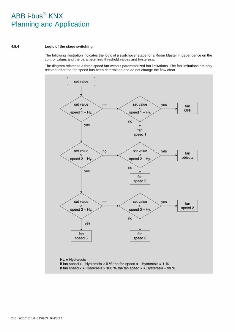
ABB i-bus KNX Planning and Application
246 2CDC 514 046 D0203 | RM/S 2.1
4.5.4 Logic of the stage switching
The following illustration indicates the logic of a switchover stage for a Room Master in dependence on the control values and the parameterized threshold values and hysteresis.
The diagram relates to a three speed fan without parameterized fan limitations. The fan limitations are only relevant after the fan speed has been determined and do not change the flow chart.
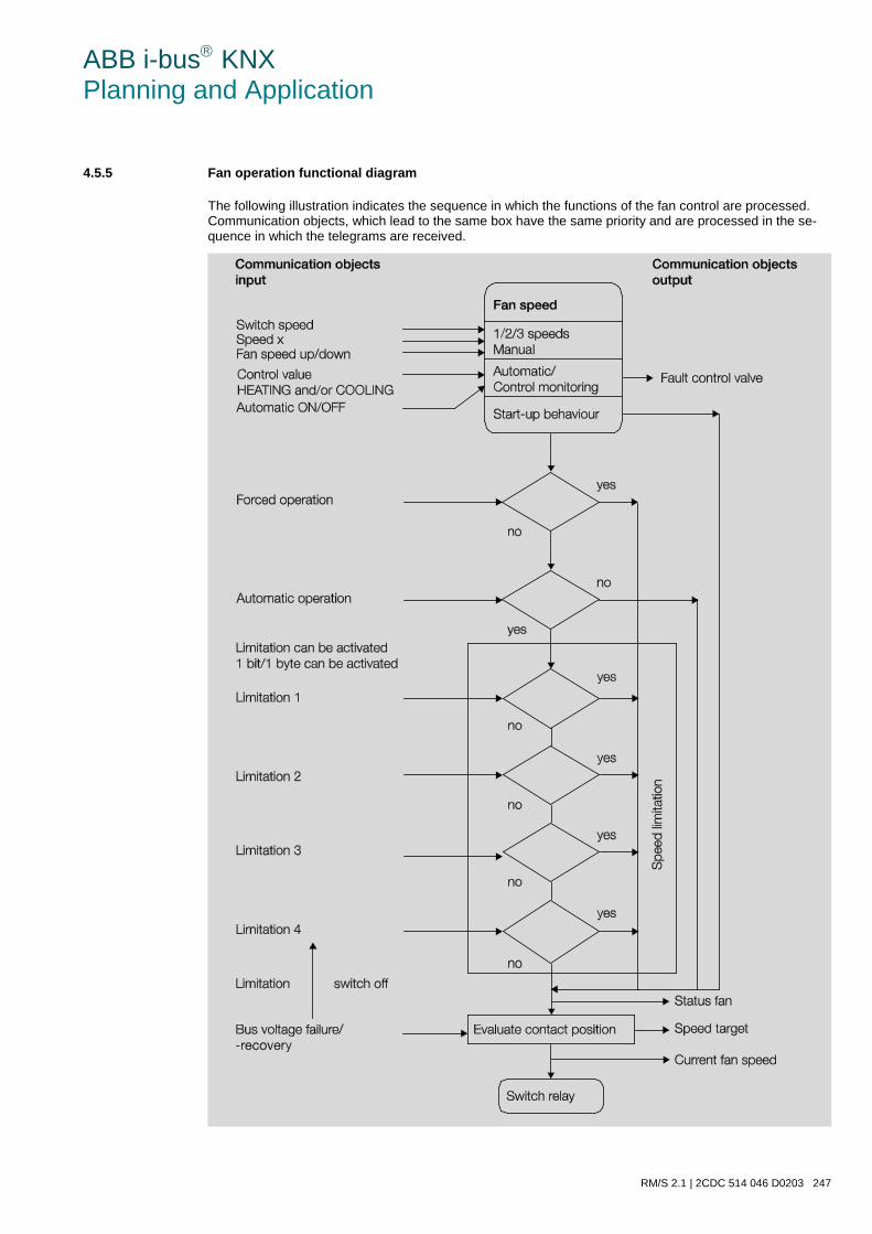
ABB i-bus KNX Planning and Application
RM/S 2.1 | 2CDC 514 046 D0203 247
4.5.5 Fan operation functional diagram
The following illustration indicates the sequence in which the functions of the fan control are processed. Communication objects, which lead to the same box have the same priority and are processed in the se-quence in which the telegrams are received.
ABB i-bus KNX Planning and Application
248 2CDC 514 046 D0203 | RM/S 2.1
4.6 Valve drives, valves and controller
4.6.1 Electromotor valve drives
Electromotor valve drives open and close valves via a small electric motor. Electromotor valve drives are offered as proportional or as 2 or 3-way valve drives.
Proportional valve drives are controlled via an analogue signal, e.g. 0…10 V. They can be controlled with the Fan Coil Actuator. 2 or 3-point valve drives are controlled via switching of the supply voltage.
2-point valve drives are controlled via the telegrams OPEN and CLOSE. The valve can only be completely open or completely closed. 2-point valves are controlled via a 2-point control or pulse width modulation (PWM). 2-point valve drives that are intended for a 2-point control cannot be controlled with the Room Master.
The Room Master does not support the control of electric motor 3-point valve drives. These are normally connected via three connection cables to a Fan Coil unit: Neutral conductor, switched phase to OPEN, switched phase for CLOSE. Using 3-point control valve drives, the valve can be opened by any desired percentage and the position can be retained over an extended period. If the valve does not move, no volt-age is applied to the motor.
The valve is opened wide enough to allow the exact quantity of hot or cold water to flow that is required to bring the heat exchanger to the required temperature. Thus the valve is controlled via the valve opening (0…100 %). The control usually used in most cases is continuous control.
4.6.2 Electro-thermal valve drives
Electro-thermal drives are adjusted due to heat expansion of a material caused by a flow of electric cur-rent. Electro-thermal valve drives are controlled by pulse width modulation. The Room Master supports the control of electro-thermal valve drives via pulse width modulation.
Electro-thermal valve drives are offered in the de-energised closed and de-energized opened variants. Depending on the variant, the valve is opened when voltage is applied and closed when no voltage is ap-plied, or vice versa.
Electro-thermal valve drives connected via two connection cables to the Room Master.
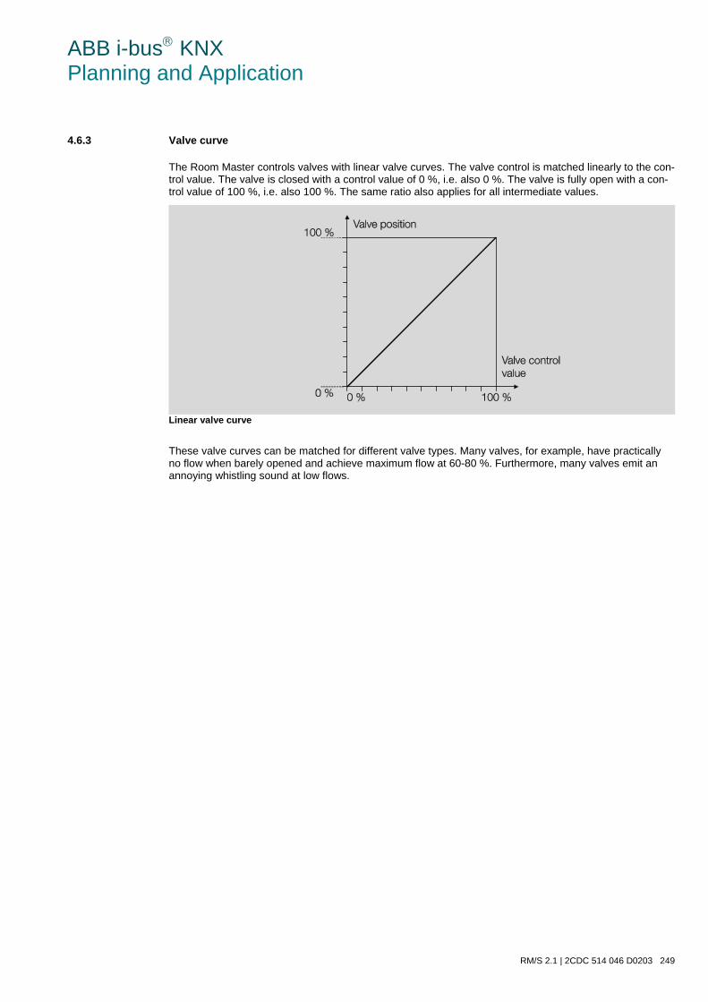
ABB i-bus KNX Planning and Application
RM/S 2.1 | 2CDC 514 046 D0203 249
4.6.3 Valve curve
The Room Master controls valves with linear valve curves. The valve control is matched linearly to the con-trol value. The valve is closed with a control value of 0 %, i.e. also 0 %. The valve is fully open with a con-trol value of 100 %, i.e. also 100 %. The same ratio also applies for all intermediate values.
Linear valve curve
These valve curves can be matched for different valve types. Many valves, for example, have practically no flow when barely opened and achieve maximum flow at 60-80 %. Furthermore, many valves emit an annoying whistling sound at low flows.
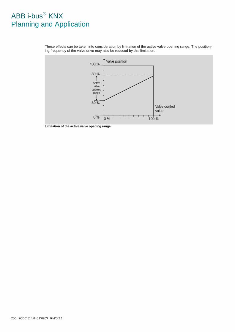
ABB i-bus KNX Planning and Application
250 2CDC 514 046 D0203 | RM/S 2.1
These effects can be taken into consideration by limitation of the active valve opening range. The position-ing frequency of the valve drive may also be reduced by this limitation.
Limitation of the active valve opening range
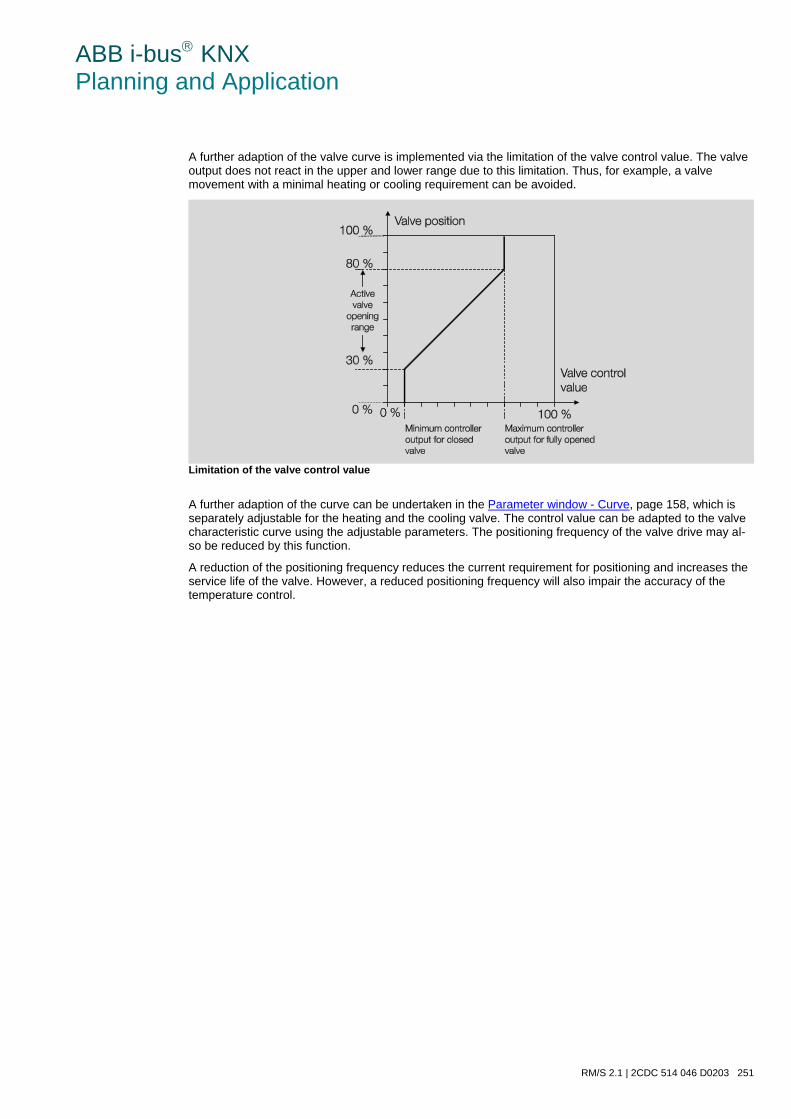
ABB i-bus KNX Planning and Application
RM/S 2.1 | 2CDC 514 046 D0203 251
A further adaption of the valve curve is implemented via the limitation of the valve control value. The valve output does not react in the upper and lower range due to this limitation. Thus, for example, a valve movement with a minimal heating or cooling requirement can be avoided.
Limitation of the valve control value
A further adaption of the curve can be undertaken in the Parameter window - Curve, page 158, which is separately adjustable for the heating and the cooling valve. The control value can be adapted to the valve characteristic curve using the adjustable parameters. The positioning frequency of the valve drive may al-so be reduced by this function.
A reduction of the positioning frequency reduces the current requirement for positioning and increases the service life of the valve. However, a reduced positioning frequency will also impair the accuracy of the temperature control.
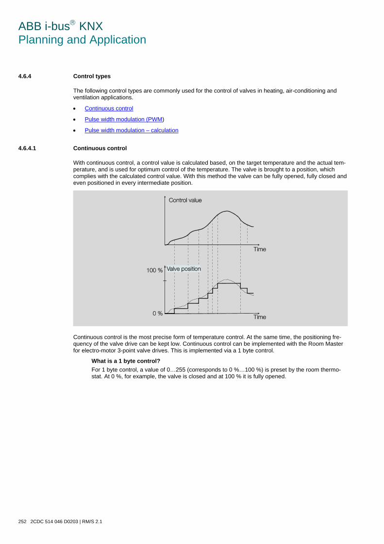
ABB i-bus KNX Planning and Application
252 2CDC 514 046 D0203 | RM/S 2.1
4.6.4 Control types
The following control types are commonly used for the control of valves in heating, air-conditioning and ventilation applications.
• Continuous control
• Pulse width modulation (PWM)
• Pulse width modulation – calculation
4.6.4.1 Continuous control
With continuous control, a control value is calculated based, on the target temperature and the actual tem-perature, and is used for optimum control of the temperature. The valve is brought to a position, which complies with the calculated control value. With this method the valve can be fully opened, fully closed and even positioned in every intermediate position.
Continuous control is the most precise form of temperature control. At the same time, the positioning fre-quency of the valve drive can be kept low. Continuous control can be implemented with the Room Master for electro-motor 3-point valve drives. This is implemented via a 1 byte control.
What is a 1 byte control? For 1 byte control, a value of 0…255 (corresponds to 0 %…100 %) is preset by the room thermo-stat. At 0 %, for example, the valve is closed and at 100 % it is fully opened.

ABB i-bus KNX Planning and Application
RM/S 2.1 | 2CDC 514 046 D0203 253
4.6.4.2 Pulse width modulation (PWM)
With pulse width modulation, the valve is operated as with 2-point control exclusively in the positions fully opened and fully closed. In contrast to a 2-point control, the position is not controlled via limit values, but rather by calculated control values similar to continuous control.
The control value is fixed for a timed cycle and recalculated in the duration for valve opening. The control value 20 % at a cycle time of 15 minutes, for example, will be recalculated for a valve opening time of three minutes. The control value 50 % results in a valve opening time of 7.5 minutes.
With pulse width modulation, a relatively accurate control of the temperature can be achieved without any resulting overshoots. Simple, attractively-priced control valves can be used. The positioning frequency of the control valve is relatively high.
Pulse width modulation can be used with the Room Master in conjunction with electro-thermal valve drives.

ABB i-bus KNX Planning and Application
254 2CDC 514 046 D0203 | RM/S 2.1
An example: When the RM/S receives a 1 byte control value (continuous control) as an input signal, and this value together with the parameterized cycle time from a PWM calculation is converted into a signal for a 2-point control (on - off - on).
With PWM control, the received control value (0…100 %) calculated in the control algorithm is converted to a pulse width modulation. The conversion is based on a constant cycle time. If the RM/S, for example, re-ceives a control value of 20 %, then for a cycle time of 15 minutes the valve will be opened for three minutes (20 % of 15 minutes) and closed for 12 minutes (80 % of 15 minutes).
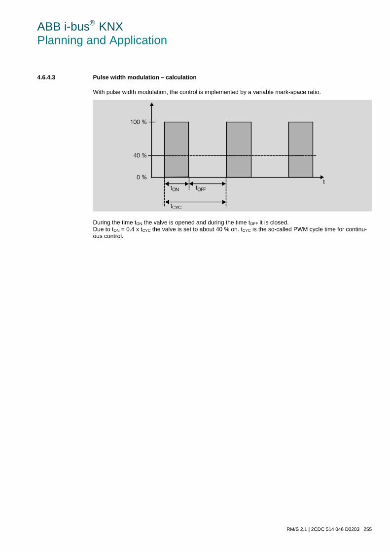
ABB i-bus KNX Planning and Application
RM/S 2.1 | 2CDC 514 046 D0203 255
4.6.4.3 Pulse width modulation – calculation
With pulse width modulation, the control is implemented by a variable mark-space ratio.
During the time tON the valve is opened and during the time tOFF it is closed. Due to tON = 0.4 x tCYC the valve is set to about 40 % on. tCYC is the so-called PWM cycle time for continu-ous control.
ABB i-bus KNX Planning and Application
256 2CDC 514 046 D0203 | RM/S 2.1
4.7 Behaviour with, …
4.7.1 Bus voltage recovery
General • At bus voltage recovery, the communication object values can be parameterized; if not they are set to
the value 0.
• Timers are out of operation and should be restarted.
• Status communication objects are sent as long as the option after a change has been set.
• The contact position is not known with 100 % certainty after bus voltage recovery. It is assumed that the contact position has not changed during the bus failure (no manual operation possibilities occur). Only after a new switch event is the contact position known to the Room Master.
• The send delay is only active at bus voltage recovery!
Switch contact output • The communication object value Staircase lighting time remains unchanged as before bus voltage
failure.
• The communication object value Disable function time is independent of the selected option.
• The communication object value Permanent ON remains unchanged as before bus voltage failure.
• The switch contact output switches as follows:
o After the set communication object value Switch with bus voltage recovery.
o If the parameter Object value “Switch” at bus voltage recovery is not parameterized, the behav-iour at bus voltage failure is decisive.
o If none of the two above options are selected, the last position is retained as with bus voltage failure.
Note
If a staircase lighting time was active at bus voltage failure, it will restart.
Note
The values of the communication objects Logical connection 1/2 are stored at bus voltage failure. The values are set again after a bus voltage recovery. If values are not assigned for communication objects Logical connection 1/2, they will be deactivated. With a reset via the bus, the values of the communication objects Logical connection 1/2 remain un-changed.
ABB i-bus KNX Planning and Application
RM/S 2.1 | 2CDC 514 046 D0203 257
Inputs • The inactive waiting time is only active at bus voltage recovery.
Valves • The purging cycle restarts if it was active before the failure.
• The priorities blocking, forced operation, purging and adjustment are re-established and executed as priorities.
The priorities are defined as follows:
1. Reference movement
2. Communication object Block
3. Communication object Forced operation
4. Valve Purge
5. Adjustment
6. Control values
Note
Here 1 corresponds to the highest priority.
• The value parameterized for bus voltage recovery is only carried out if no higher priority (with the ex-ception of manual operation/reference movement) was active before the failure. If during bus voltage recovery and an active priority a new control value is received, it will replace the Control value that was defined in the parameterization.
Blind The behaviour of the shutter/blind output is programmable. The output can assume any state or remain unchanged.
Note
The position of the blind or the shutter is saved at bus voltage failure if the function Automatic is activat-ed. The blind or shutter remain in the same position. At bus voltage recovery, the position is retained and the value of the communication object is undefined. The value is only updated after a renewed motion telegram. If the communication object Automatic ON/OFF has not been assigned to a group address, the function Automatic is deactivated at a download.
ABB i-bus KNX Planning and Application
258 2CDC 514 046 D0203 | RM/S 2.1
4.7.2 Reset via bus
What is an ETS reset? Generally an ETS reset is defined as a reset of the device via the ETS. The ETS reset is initiated in the ETS3 under the menu item Commissioning with the function Reset device. This stops the user program and it is restarted.
Note
For all resets after delivery including the first download, the response will comply with that of a reset via the bus. A send and switch delay is not executed. All states are reset.
Switch contact output • The communication object value Staircase lighting time receives its parameterized value.
• The communication object value Disable function time is 0, i.e. function Time is not blocked.
• The object value Permanent ON is 0, i.e. permanent on is not active.
• The switch contact output goes to the safely opened state.
Note
The values of the communication objects Logical connection 1/2 are stored at bus voltage failure. The values are set again after a bus voltage recovery. If values are not assigned for communication objects Logical connection 1/2, they will be deactivated. With a reset via the bus, the values of the communication objects Logical connection 1/2 remain un-changed.
Blind/Shutter
Note
The position of the blind or the shutter is saved at bus voltage failure if the function Automatic is activat-ed. The blind or shutter remain in the same position. At bus voltage recovery, the position is retained and the value of the communication object is undefined. The value is only updated after a renewed motion telegram. If the communication object Automatic ON/OFF has not been assigned to a group address, the function Automatic is deactivated at a download.
ABB i-bus KNX Planning and Application
RM/S 2.1 | 2CDC 514 046 D0203 259
4.7.3 Download
General After a change of the fan control (speed control or changeover control) of the fan type, a full reset of the Room Master is required in order to avoid incorrect function. This full reset has the same effect as reset of the device in the ETS. In this case, the communication objects are normally written with the value 0. The timers stop and are set to 0. Status communication objects are set to 0 (with the exception of automatic, if it is active) and contacts are opened.
With the normal download, where no re-parameterization of the fan type and fan control has occurred, an action has the effect that in the ideal case no unwanted reactions are initiated and thus normal operation is not influenced. . Communication object values remain unchanged. Timer will not operate and must only be restarted. Status values are updated and sent. The contact position remains unchanged and only changes with the next switch telegram.
Note
After a download with a change, the application complies in behaviour to a reset of the device in the ETS.
Switch contact output The communication object value Staircase lighting time remains unchanged.
The communication object value Disable function time remains unchanged.
Exception: The communication object value is set to 0 if there is no assignment to the communica-tion object.
Note
Otherwise, the block for the function Time is removed, if the communication object Disable func-tion time is not available. The switch contact output will otherwise use the new parameters.
The communication object value Permanent ON remains unchanged.
The switch contact output remains unchanged.
Blind/Shutter
Note
If the communication object Automatic ON/OFF has not been assigned to a group address, the function Automatic is deactivated at a download.
ABB i-bus KNX Planning and Application
260 2CDC 514 046 D0203 | RM/S 2.1
4.7.4 Reaction on bus voltage failure
After the contact positions have set with bus voltage failure, the Room Master remains functional until the bus voltage recovers.
Note
The values of the communication objects Logical connection 1/2 are stored at bus voltage failure. The values are set again after a bus voltage recovery. If values are not assigned for communication objects Logical connection 1/2, they will be deactivated. With a reset via the bus, the values of the communication objects Logical connection 1/2 remain un-changed.
Only the energy for a non-delayed switching action for each output is available should the bus voltage fail. Reversing times, dwell times and start-up behaviour cannot be considered. For this reason, it is only pos-sible for the fan at bus voltage recovery to retain the fan speed (unchanged) or to switch off.
The special behaviour is described in the following table.
Blind The behaviour of the shutter/blind output is programmable. The output can assume any state or remain unchanged.
Note
The position of the blind or the shutter is saved at bus voltage failure if the function Automatic is activat-ed. The blind or shutter remain in the same position. At bus voltage recovery, the position is retained and the value of the communication object is undefined. The value is only updated after a renewed motion telegram. If the communication object Automatic ON/OFF has not been assigned to a group address, the function Automatic is deactivated at a download.
ABB i-bus KNX Planning and Application
RM/S 2.1 | 2CDC 514 046 D0203 261
4.8 Priorities with, …
4.8.1 Valve HEATING/COOLING
The priorities are defined as follows:
1. Reference movement
2. Communication object Block
3. Communication object Forced operation
4. Valve Purge
5. Adjustment
6. Control values
Note
Here 1 corresponds to the highest priority.
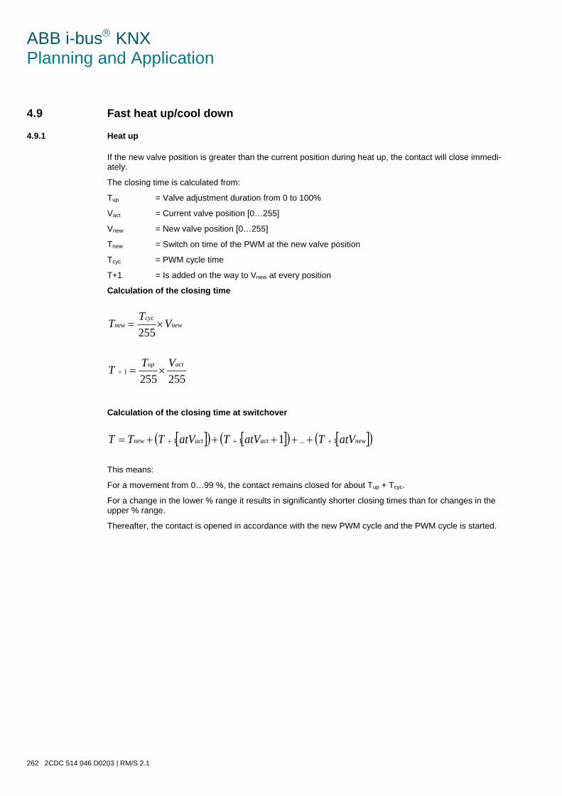
ABB i-bus KNX Planning and Application
262 2CDC 514 046 D0203 | RM/S 2.1
4.9 Fast heat up/cool down
4.9.1 Heat up
If the new valve position is greater than the current position during heat up, the contact will close immedi-ately.
The closing time is calculated from:
Tup = Valve adjustment duration from 0 to 100%
Vact = Current valve position [0…255]
Vnew = New valve position [0…255]
Tnew = Switch on time of the PWM at the new valve position
Tcyc = PWM cycle time
T+1 = Is added on the way to Vnew at every position
Calculation of the closing time
newcyc
new VTT ×=255
2552551
actup VTT ×=+
Calculation of the closing time at switchover
[ ]( ) [ ]( ) [ ]( )newactactnew atVTatVTatVTTT 1...11 1 +++ +++++=
This means:
For a movement from 0…99 %, the contact remains closed for about Tup + Tcyc.
For a change in the lower % range it results in significantly shorter closing times than for changes in the upper % range.
Thereafter, the contact is opened in accordance with the new PWM cycle and the PWM cycle is started.
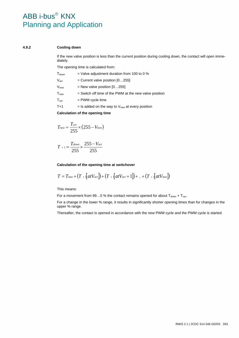
ABB i-bus KNX Planning and Application
RM/S 2.1 | 2CDC 514 046 D0203 263
4.9.2 Cooling down
If the new valve position is less than the current position during cooling down, the contact will open imme-diately.
The opening time is calculated from:
Tdown = Valve adjustment duration from 100 to 0 %
Vact = Current valve position [0…255]
Vnew = New valve position [0…255]
Tnew = Switch off time of the PWM at the new valve position
Tcyc = PWM cycle time
T+1 = Is added on the way to Vnew at every position
Calculation of the opening time
( )newcyc
new VTT −×= 255255
255255
2551
actdown VTT −×=+
Calculation of the opening time at switchover
[ ]( ) [ ]( ) [ ]( )newactactnew atVTatVTatVTTT 1...11 1 +++ +++++=
This means:
For a movement from 99…0 % the contact remains opened for about Tdown + Tcyc.
For a change in the lower % range, it results in significantly shorter opening times than for changes in the upper % range.
Thereafter, the contact is opened in accordance with the new PWM cycle and the PWM cycle is started.
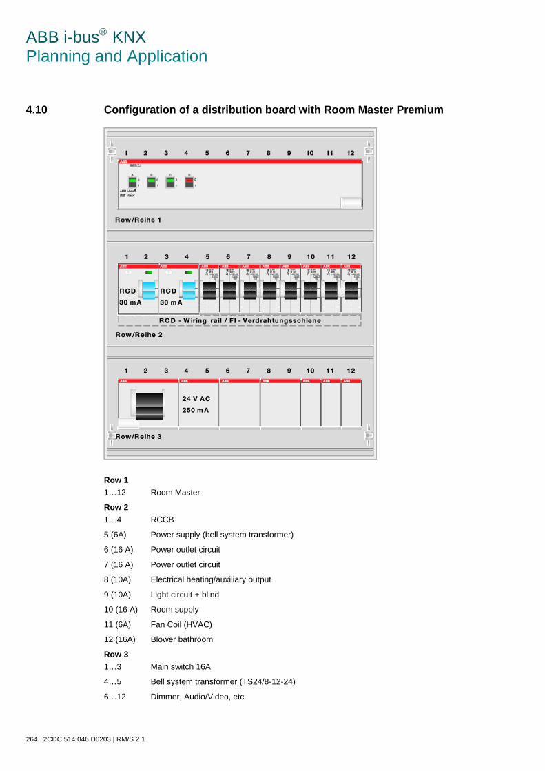
ABB i-bus KNX Planning and Application
264 2CDC 514 046 D0203 | RM/S 2.1
4.10 Configuration of a distribution board with Room Master Premium
Row 1 1…12 Room Master
Row 2 1…4 RCCB
5 (6A) Power supply (bell system transformer)
6 (16 A) Power outlet circuit
7 (16 A) Power outlet circuit
8 (10A) Electrical heating/auxiliary output
9 (10A) Light circuit + blind
10 (16 A) Room supply
11 (6A) Fan Coil (HVAC)
12 (16A) Blower bathroom
Row 3 1…3 Main switch 16A
4…5 Bell system transformer (TS24/8-12-24)
6…12 Dimmer, Audio/Video, etc.
ABB i-bus KNX Pre-configuration
RM/S 2.1 | 2CDC 514 046 D0203 265
5 Pre-configuration
In this chapter, the method of function of the Room Scenarios is described. Furthermore, you will find an overview of the pre-configured settings of the RM/S. These are explained using the pre-configured Room Scenarios.
5.1 Pre-configured Room Scenarios
In total, eight of the sixteen possible Room Scenarios are already pre-configured.
The first three Room Scenarios (RS) are triggered externally by reception:
• RS 1: Check In – Room occupied
• RS 2: Check Out – Room not occupied
• RS 3: Standby – Release the room for service
The next five Room Scenarios (RS) are triggered internally via the binary inputs:
• RS 4: Emergency pressed (in the bathroom)
• RS 5: Remove key card (at the room entrance)
• RS 6: Insert key card (at the room entrance)
• RS 7: Master OFF (on the bed)
• RS 8: Master ON (on the bed)
The Room Scenarios 9…16 are not used.
5.2 Prerequisites for commissioning
The following preconditions must be fulfilled in order to put the preconfigured RM/S completely into opera-tion.
Connections of the outputs to: • Room supply/outlets
• Floor or desk light socket
• Blower bathroom
• Auxiliary electrical heater
• Lamps: Bed left/right, main room 1/2, hall, bathroom
• Blind
• Fan 1…3, valves
• Thermostat, e.g. RDF/A
Important
The maximum permissible current of a KNX line may not be exceeded. During planning and installation ensure that the KNX line is correctly dimensioned. The device features a maximum current consumption of 24 mA (Fan-In 2).
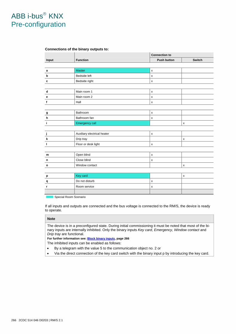
ABB i-bus KNX Pre-configuration
266 2CDC 514 046 D0203 | RM/S 2.1
Connections of the binary outputs to:
Input Function Connection to
Push button Switch
a Master x
b Bedside left x
c Bedside right x
d Main room 1 x
e Main room 2 x
f Hall x
g Bathroom x
h Bathroom fan x
i Emergency call x
j Auxiliary electrical heater x
k Drip tray x
l Floor or desk light x
m Open blind x
n Close blind x
o Window contact x
p Key card x
q Do not disturb x
r Room service x
Special Room Scenario
If all inputs and outputs are connected and the bus voltage is connected to the RM/S, the device is ready to operate.
Note
The device is in a preconfigured state. During initial commissioning it must be noted that most of the bi-nary inputs are internally inhibited. Only the binary inputs Key card, Emergency, Window contact and Drip tray are functional. For further information see: Block binary inputs, page 266 The inhibited inputs can be enabled as follows: • By a telegram with the value 5 to the communication object no. 2 or • Via the direct connection of the key card switch with the binary input p by introducing the key card.
ABB i-bus KNX Pre-configuration
RM/S 2.1 | 2CDC 514 046 D0203 267
5.3 Preconfigured binary inputs
In this chapter, you will find all preconfigured settings for the binary inputs. They are represented in a table sorted by themes to provide the fastest overview.
• Block binary inputs
• Operating modes:
o Operating mode Switch sensor
o Operating mode Blind sensor
o Operating mode Value/Forced operation
• Scan binary inputs
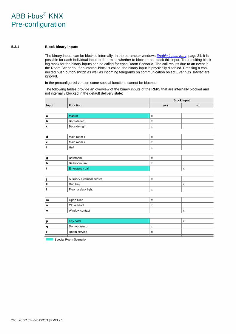
ABB i-bus KNX Pre-configuration
268 2CDC 514 046 D0203 | RM/S 2.1
5.3.1 Block binary inputs
The binary inputs can be blocked internally. In the parameter windows Enable inputs x…y, page 34, it is possible for each individual input to determine whether to block or not block this input. The resulting block-ing mask for the binary inputs can be called for each Room Scenario. The call results due to an event in the Room Scenario. If an internal block is called, the binary input is physically disabled. Pressing a con-nected push button/switch as well as incoming telegrams on communication object Event 0/1 started are ignored.
In the preconfigured version some special functions cannot be blocked.
The following tables provide an overview of the binary inputs of the RM/S that are internally blocked and not internally blocked in the default delivery state:
Input Function Block input
yes no
a Master x
b Bedside left x
c Bedside right x
d Main room 1 x
e Main room 2 x
f Hall x
g Bathroom x
h Bathroom fan x
i Emergency call x
j Auxiliary electrical heater x
k Drip tray x
l Floor or desk light x
m Open blind x
n Close blind x
o Window contact x
p Key card x
q Do not disturb x
r Room service x
Special Room Scenario
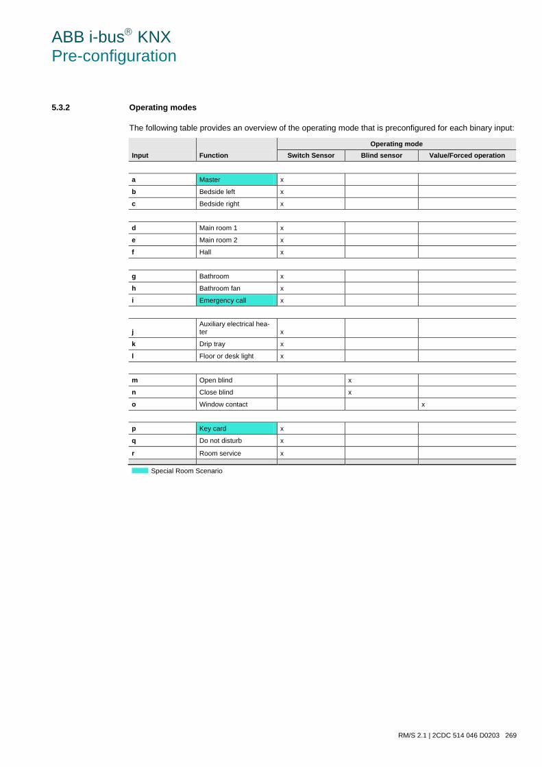
ABB i-bus KNX Pre-configuration
RM/S 2.1 | 2CDC 514 046 D0203 269
5.3.2 Operating modes
The following table provides an overview of the operating mode that is preconfigured for each binary input:
Input Function Operating mode
Switch Sensor Blind sensor Value/Forced operation
a Master x
b Bedside left x
c Bedside right x
d Main room 1 x
e Main room 2 x
f Hall x
g Bathroom x
h Bathroom fan x
i Emergency call x
j Auxiliary electrical hea-ter x
k Drip tray x
l Floor or desk light x
m Open blind x
n Close blind x
o Window contact x
p Key card x
q Do not disturb x
r Room service x
Special Room Scenario
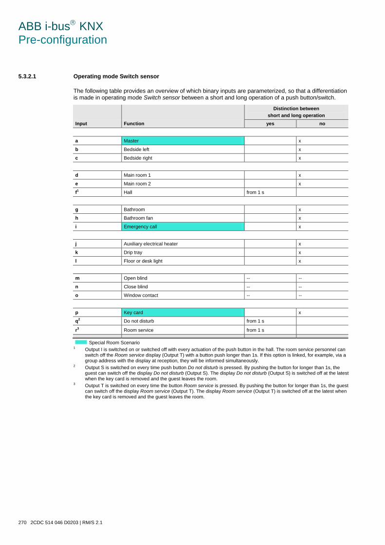
ABB i-bus KNX Pre-configuration
270 2CDC 514 046 D0203 | RM/S 2.1
5.3.2.1 Operating mode Switch sensor
The following table provides an overview of which binary inputs are parameterized, so that a differentiation is made in operating mode Switch sensor between a short and long operation of a push button/switch.
Input Function
Distinction between short and long operation
yes no
a Master x
b Bedside left x
c Bedside right x
d Main room 1 x
e Main room 2 x
f1 Hall from 1 s
g Bathroom x
h Bathroom fan x
i Emergency call x
j Auxiliary electrical heater x
k Drip tray x
l Floor or desk light x
m Open blind -- --
n Close blind -- --
o Window contact -- --
p Key card x
q2 Do not disturb from 1 s
r3 Room service from 1 s
Special Room Scenario
1 Output I is switched on or switched off with every actuation of the push button in the hall. The room service personnel can switch off the Room service display (Output T) with a button push longer than 1s. If this option is linked, for example, via a group address with the display at reception, they will be informed simultaneously.
2 Output S is switched on every time push button Do not disturb is pressed. By pushing the button for longer than 1s, the guest can switch off the display Do not disturb (Output S). The display Do not disturb (Output S) is switched off at the latest when the key card is removed and the guest leaves the room.
3 Output T is switched on every time the button Room service is pressed. By pushing the button for longer than 1s, the guest can switch off the display Room service (Output T). The display Room service (Output T) is switched off at the latest when the key card is removed and the guest leaves the room.
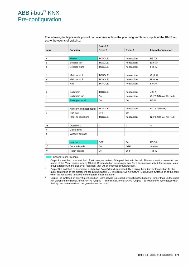
ABB i-bus KNX Pre-configuration
RM/S 2.1 | 2CDC 514 046 D0203 271
The following table presents you with an overview of how the preconfigured binary inputs of the RM/S re-act to the events of switch 1:
Input Function Switch 1
Internal connection Event 0 Event 1
a Master TOGGLE no reaction RS 7/8
b Bedside left TOGGLE no reaction E (6 A)
c Bedside right TOGGLE no reaction F (6 A)
d Main room 1 TOGGLE no reaction G (6 A)
e Main room 2 TOGGLE no reaction H (6 A)
f1 Hall TOGGLE no reaction I (6 A)
g Bathroom TOGGLE no reaction J (6 A)
h Bathroom fan ON no reaction C (20 A/16 AX C-Load)
i Emergency call ON ON RS ¾
j Auxiliary electrical heater TOGGLE no reaction D (16 A/10 AX)
k Drip tray OFF ON --
l Floor or desk light TOGGLE no reaction B (20 A/16 AX C-Load)
m Open blind -- -- --
n Close blind -- -- --
o Window contact -- -- --
p Key card OFF ON RS 5/6
q2 Do not disturb ON OFF S (6 A)
r3 Room service ON OFF T (6 A)
Special Room Scenario
1 Output I is switched on or switched off with every actuation of the push button in the hall. The room service personnel can switch off the Room service display (Output T) with a button push longer than 1s. If this option is linked, for example, via a group address with the display at reception, they will be informed simultaneously .
2 Output S is switched on every time push button Do not disturb is pressed. By pushing the button for longer than 1s, the guest can switch off the display Do not disturb (Output S). The display Do not disturb (Output S) is switched off at the latest when the key card is removed and the guest leaves the room.
3 Output T is switched on every time the button Room service is pressed. By pushing the button for longer than 1s, the guest can switch off the display Room service (Output T). The display Room service (Output T) is switched off at the latest when the key card is removed and the guest leaves the room.
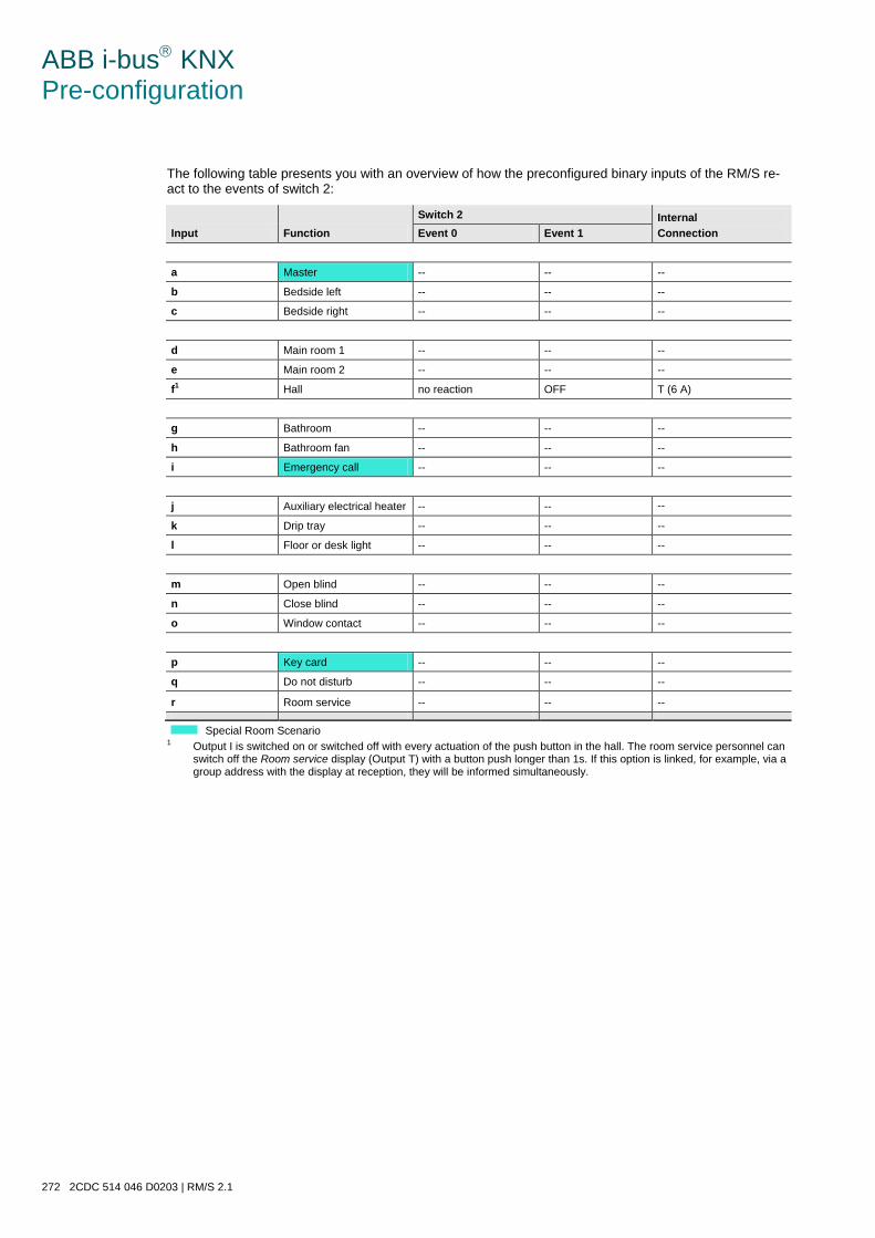
ABB i-bus KNX Pre-configuration
272 2CDC 514 046 D0203 | RM/S 2.1
The following table presents you with an overview of how the preconfigured binary inputs of the RM/S re-act to the events of switch 2:
Input Function Switch 2 Internal
Connection Event 0 Event 1
a Master -- -- --
b Bedside left -- -- --
c Bedside right -- -- --
d Main room 1 -- -- --
e Main room 2 -- -- --
f1 Hall no reaction OFF T (6 A)
g Bathroom -- -- --
h Bathroom fan -- -- --
i Emergency call -- -- --
j Auxiliary electrical heater -- -- --
k Drip tray -- -- --
l Floor or desk light -- -- --
m Open blind -- -- --
n Close blind -- -- --
o Window contact -- -- --
p Key card -- -- --
q Do not disturb -- -- --
r Room service -- -- --
Special Room Scenario
1 Output I is switched on or switched off with every actuation of the push button in the hall. The room service personnel can switch off the Room service display (Output T) with a button push longer than 1s. If this option is linked, for example, via a group address with the display at reception, they will be informed simultaneously.
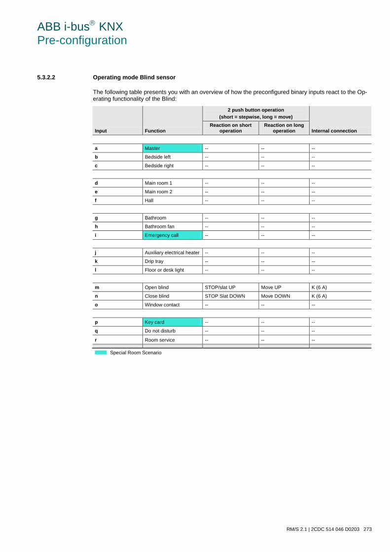
ABB i-bus KNX Pre-configuration
RM/S 2.1 | 2CDC 514 046 D0203 273
5.3.2.2 Operating mode Blind sensor
The following table presents you with an overview of how the preconfigured binary inputs react to the Op-erating functionality of the Blind:
Input Function
2 push button operation (short = stepwise, long = move)
Internal connection Reaction on short
operation Reaction on long
operation
a Master -- -- --
b Bedside left -- -- --
c Bedside right -- -- --
d Main room 1 -- -- --
e Main room 2 -- -- --
f Hall -- -- --
g Bathroom -- -- --
h Bathroom fan -- -- --
i Emergency call -- -- --
j Auxiliary electrical heater -- -- --
k Drip tray -- -- --
l Floor or desk light -- -- --
m Open blind STOP/slat UP Move UP K (6 A)
n Close blind STOP Slat DOWN Move DOWN K (6 A)
o Window contact -- -- --
p Key card -- -- --
q Do not disturb -- -- --
r Room service -- -- --
Special Room Scenario
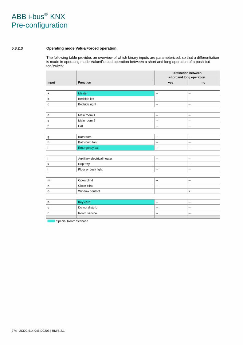
ABB i-bus KNX Pre-configuration
274 2CDC 514 046 D0203 | RM/S 2.1
5.3.2.3 Operating mode Value/Forced operation
The following table provides an overview of which binary inputs are parameterized, so that a differentiation is made in operating mode Value/Forced operation between a short and long operation of a push but-ton/switch:
Input Function
Distinction between short and long operation
yes no
a Master -- --
b Bedside left -- --
c Bedside right -- --
d Main room 1 -- --
e Main room 2 -- --
f Hall -- --
g Bathroom -- --
h Bathroom fan -- --
i Emergency call -- --
j Auxiliary electrical heater -- --
k Drip tray -- --
l Floor or desk light -- --
m Open blind -- --
n Close blind -- --
o Window contact x
p Key card -- --
q Do not disturb -- --
r Room service -- --
Special Room Scenario
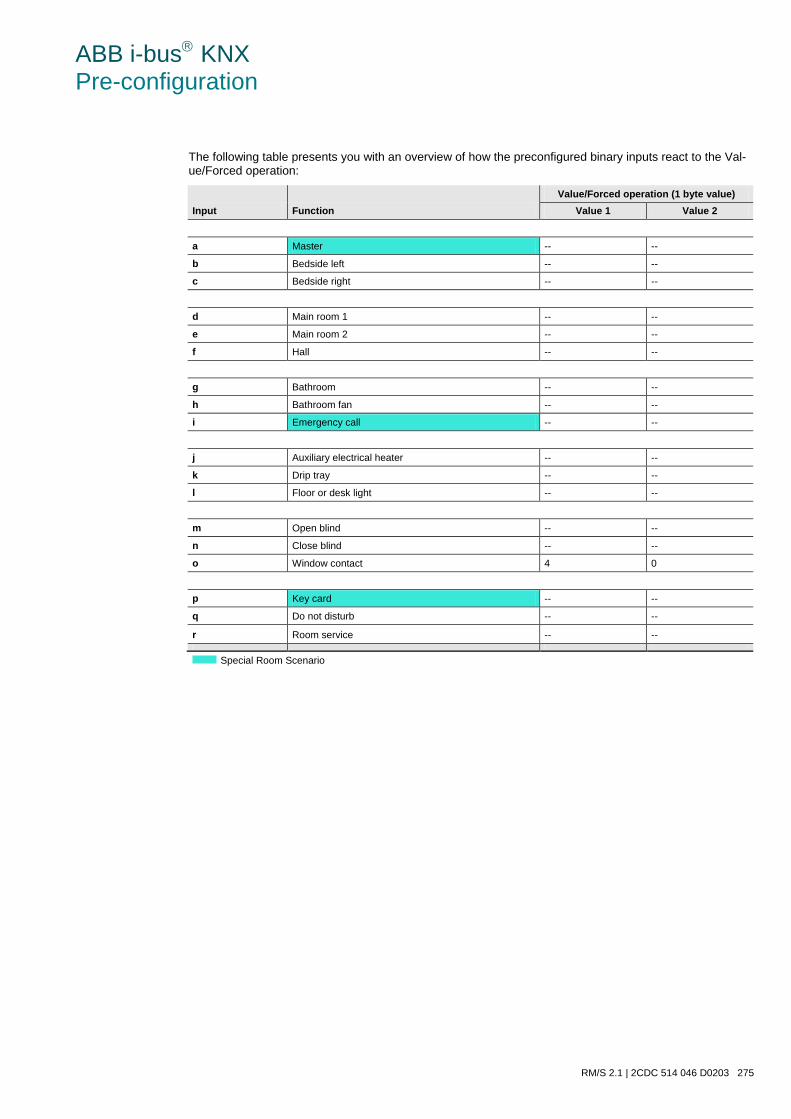
ABB i-bus KNX Pre-configuration
RM/S 2.1 | 2CDC 514 046 D0203 275
The following table presents you with an overview of how the preconfigured binary inputs react to the Val-ue/Forced operation:
Input Function Value/Forced operation (1 byte value)
Value 1 Value 2
a Master -- --
b Bedside left -- --
c Bedside right -- --
d Main room 1 -- --
e Main room 2 -- --
f Hall -- --
g Bathroom -- --
h Bathroom fan -- --
i Emergency call -- --
j Auxiliary electrical heater -- --
k Drip tray -- --
l Floor or desk light -- --
m Open blind -- --
n Close blind -- --
o Window contact 4 0
p Key card -- --
q Do not disturb -- --
r Room service -- --
Special Room Scenario
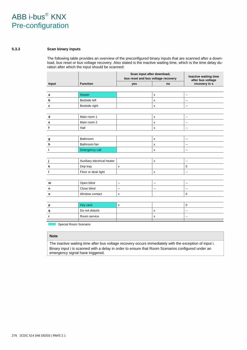
ABB i-bus KNX Pre-configuration
276 2CDC 514 046 D0203 | RM/S 2.1
5.3.3 Scan binary inputs
The following table provides an overview of the preconfigured binary inputs that are scanned after a down-load, bus reset or bus voltage recovery. Also stated is the inactive waiting time, which is the time delay du-ration after which the input should be scanned:
Input Function
Scan input after download, bus reset and bus voltage recovery Inactive waiting time
after bus voltage recovery in s yes no
a Master x --
b Bedside left x --
c Bedside right x --
d Main room 1 x --
e Main room 2 x --
f Hall x --
g Bathroom x --
h Bathroom fan x --
i Emergency call x --
j Auxiliary electrical heater x --
k Drip tray x 0
l Floor or desk light x --
m Open blind -- -- --
n Close blind -- -- --
o Window contact x 0
p Key card x 0
q Do not disturb x --
r Room service x --
Special Room Scenario
Note
The inactive waiting time after bus voltage recovery occurs immediately with the exception of input i. Binary input i is scanned with a delay in order to ensure that Room Scenarios configured under an emergency signal have triggered.
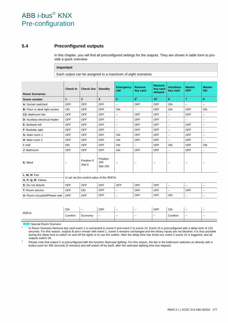
ABB i-bus KNX Pre-configuration
RM/S 2.1 | 2CDC 514 046 D0203 277
5.4 Preconfigured outputs
In this chapter, you will find all preconfigured settings for the outputs. They are shown in table form to pro-vide a quick overview.
Important
Each output can be assigned to a maximum of eight scenarios.
Room Scenarios
Check In Check Out Standby Emergency call
Remove key card
Remove key card delayed
Introduce key card
Master OFF
Master ON
Scene number 1 2 3 4 51 151 6 7 8
A: Socket switched OFF OFF OFF -- OFF OFF ON -- --
B: Floor or desk light socket ON OFF OFF ON -- OFF ON OFF ON
C2: Bathroom fan OFF OFF OFF -- OFF OFF -- OFF --
D: Auxiliary electrical heater OFF OFF OFF -- OFF OFF -- -- --
E: Bedside left OFF OFF OFF -- OFF OFF -- OFF --
F: Bedside right OFF OFF OFF -- OFF OFF -- OFF --
G: Main room 1 OFF OFF OFF ON OFF OFF -- OFF --
H: Main room 2 OFF OFF OFF ON OFF OFF -- OFF --
I: Hall ON OFF OFF ON -- OFF ON OFF ON
J: Bathroom OFF OFF OFF ON OFF OFF -- OFF --
K: Blind -- Position 0 Slat 0
Position 100 Slat 100
-- -- -- -- -- --
L, M, N: Fan Is set via the control value of the RDF/A.
O, P, Q, R: Valves
S: Do not disturb OFF OFF OFF OFF OFF OFF -- -- --
T: Room service OFF ON OFF -- OFF OFF -- OFF --
U: Room occupied/Please wait OFF OFF OFF -- OFF OFF ON -- --
RDF/A ON -- OFF -- -- OFF ON -- --
Comfort Economy -- -- -- -- Comfort -- --
Special Room Scenario
1 In Room Scenario Remove key card event 1 is connected to scene 5 and event 2 to scene 15. Event 15 is preconfigured with a delay time of 120 seconds. For this reason, outputs B and I remain with event 1, scene 5 remains unchanged and the binary inputs are not blocked. It is thus possible during the delay time to switch on and off the lights or to use the outlets. After the delay time has timed out, event 2 scene 15 is triggered, and all outputs switch off.
2 Please note that output C is preconfigured with the function Staircase lighting. For this reason, the fan in the bathroom switches on directly with a button push for 300 seconds (5 minutes) and will switch off by itself, after the staircase lighting time has elapsed.
ABB i-bus KNX Pre-configuration
278 2CDC 514 046 D0203 | RM/S 2.1
5.5 Triggering Room Scenarios
A Room Scenario consists of two events. Thereby, one event will trigger up to seven telegrams immediate-ly, and the other event can trigger the same seven telegrams via a delay set with a timer.
Each of these events can be parameterized individually:
• Sending of two 1 bit values,
• Activation of the automatic function of a blind,
• Triggering a KNX scene, internally or via the bus,
• Deactivation/activation of the internal block of the binary inputs,
• Switching on/off the thermostat, e.g. RDF/A,
• Activation of the thermostat, e.g. RDF/A, with a defined operating mode.
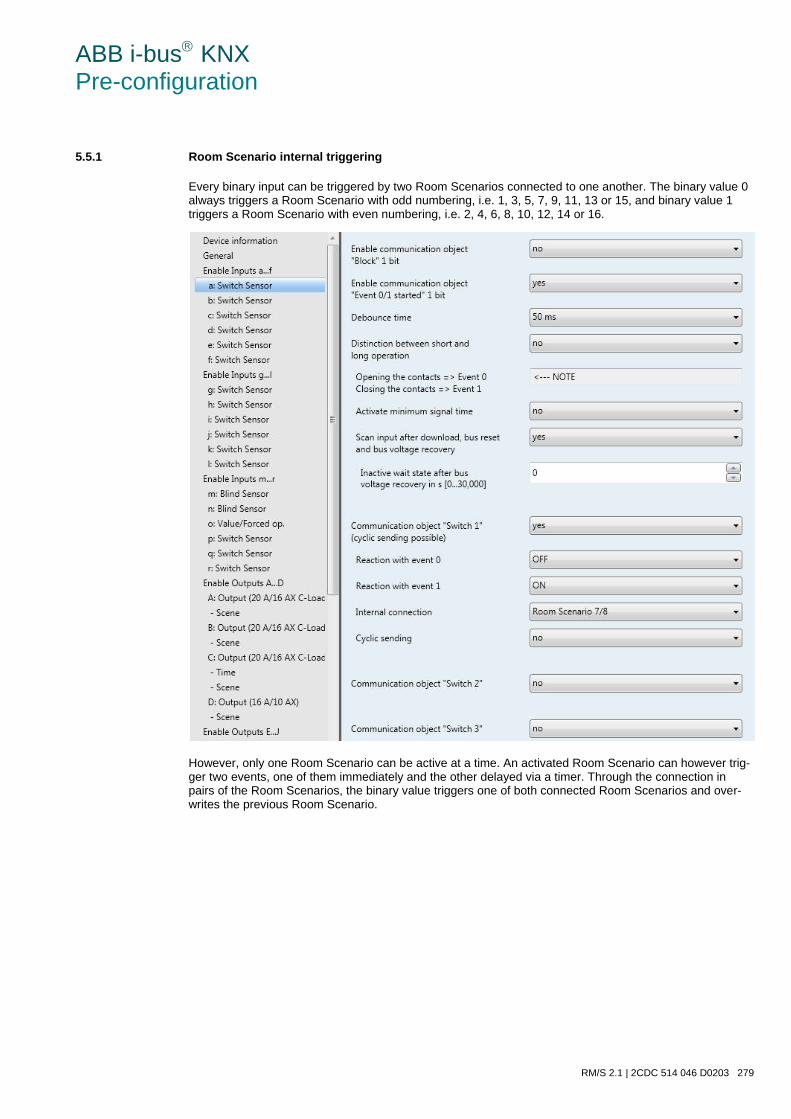
ABB i-bus KNX Pre-configuration
RM/S 2.1 | 2CDC 514 046 D0203 279
5.5.1 Room Scenario internal triggering
Every binary input can be triggered by two Room Scenarios connected to one another. The binary value 0 always triggers a Room Scenario with odd numbering, i.e. 1, 3, 5, 7, 9, 11, 13 or 15, and binary value 1 triggers a Room Scenario with even numbering, i.e. 2, 4, 6, 8, 10, 12, 14 or 16.
However, only one Room Scenario can be active at a time. An activated Room Scenario can however trig-ger two events, one of them immediately and the other delayed via a timer. Through the connection in pairs of the Room Scenarios, the binary value triggers one of both connected Room Scenarios and over-writes the previous Room Scenario.
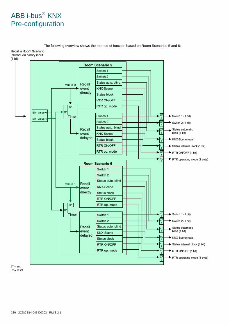
ABB i-bus KNX Pre-configuration
280 2CDC 514 046 D0203 | RM/S 2.1
The following overview shows the method of function based on Room Scenarios 5 and 6:
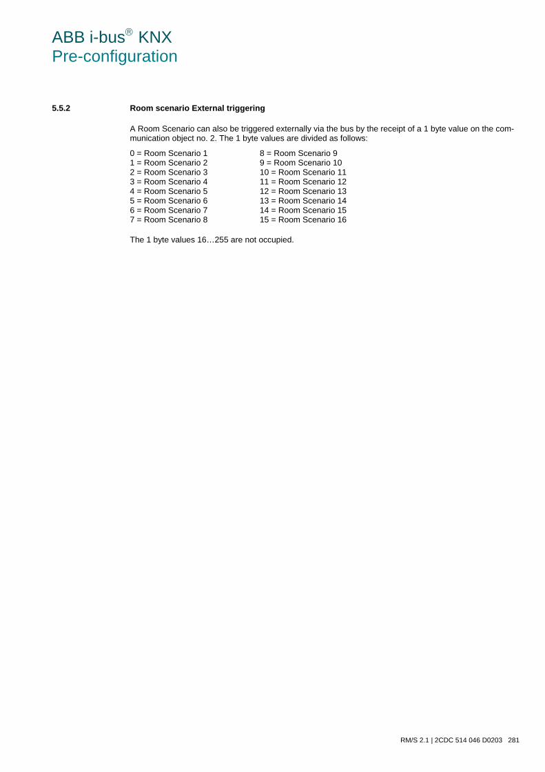
ABB i-bus KNX Pre-configuration
RM/S 2.1 | 2CDC 514 046 D0203 281
5.5.2 Room scenario External triggering
A Room Scenario can also be triggered externally via the bus by the receipt of a 1 byte value on the com-munication object no. 2. The 1 byte values are divided as follows:
0 = Room Scenario 1 8 = Room Scenario 9 1 = Room Scenario 2 9 = Room Scenario 10 2 = Room Scenario 3 10 = Room Scenario 11 3 = Room Scenario 4 11 = Room Scenario 12 4 = Room Scenario 5 12 = Room Scenario 13 5 = Room Scenario 6 13 = Room Scenario 14 6 = Room Scenario 7 14 = Room Scenario 15 7 = Room Scenario 8 15 = Room Scenario 16
The 1 byte values 16…255 are not occupied.
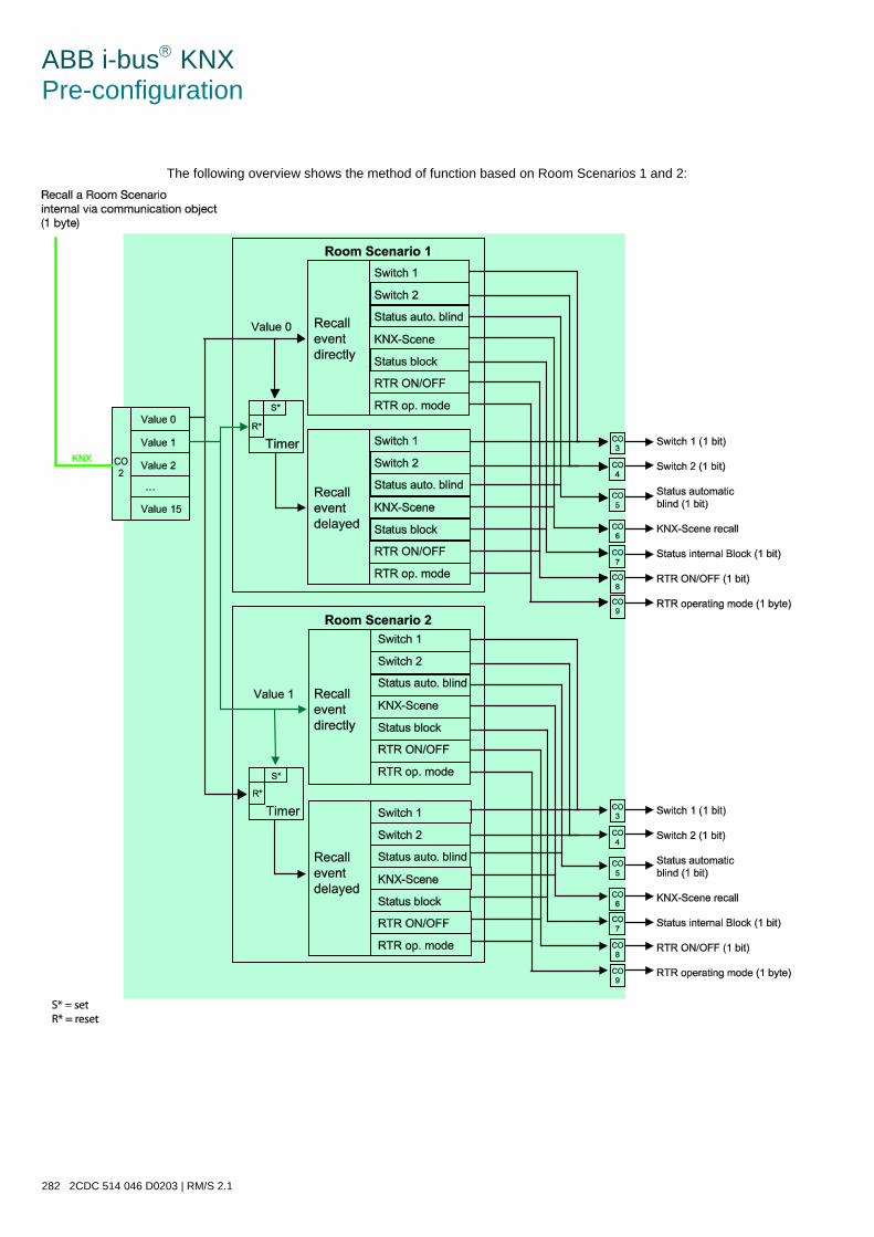
ABB i-bus KNX Pre-configuration
282 2CDC 514 046 D0203 | RM/S 2.1
The following overview shows the method of function based on Room Scenarios 1 and 2:
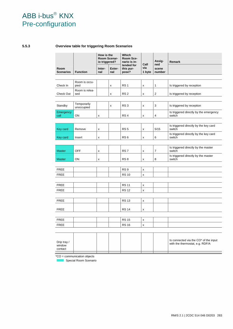
ABB i-bus KNX Pre-configuration
RM/S 2.1 | 2CDC 514 046 D0203 283
5.5.3 Overview table for triggering Room Scenarios
Room Scenarios Function
How is the Room Scenar-io triggered?
Which Room Sce-nario is in-tended for this pur-pose?
Call via 1 byte
Assig-ned scene number
Remark
Inter-nal
Exter-nal
Check In Room is occu-pied x RS 1 x 1 Is triggered by reception
Check Out Room is relea-sed x RS 2 x 2 Is triggered by reception
Standby Temporarily unoccupied x RS 3 x 3 Is triggered by reception
Emergency call ON x RS 4 x 4
Is triggered directly by the emergency switch
Key card Remove x RS 5 x 5/15 Is triggered directly by the key card switch
Key card Insert x RS 6 x 6 Is triggered directly by the key card switch
Master OFF x RS 7 x 7 Is triggered directly by the master switch
Master ON x RS 8 x 8 Is triggered directly by the master switch
FREE RS 9 x
FREE RS 10 x
FREE RS 11 x
FREE RS 12 x
FREE RS 13 x
FREE RS 14 x
FREE RS 15 x
FREE RS 16 x
Drip tray / window contact
Is connected via the CO* of the input with the thermostat, e.g. RDF/A
*CO = communication objects
Special Room Scenario
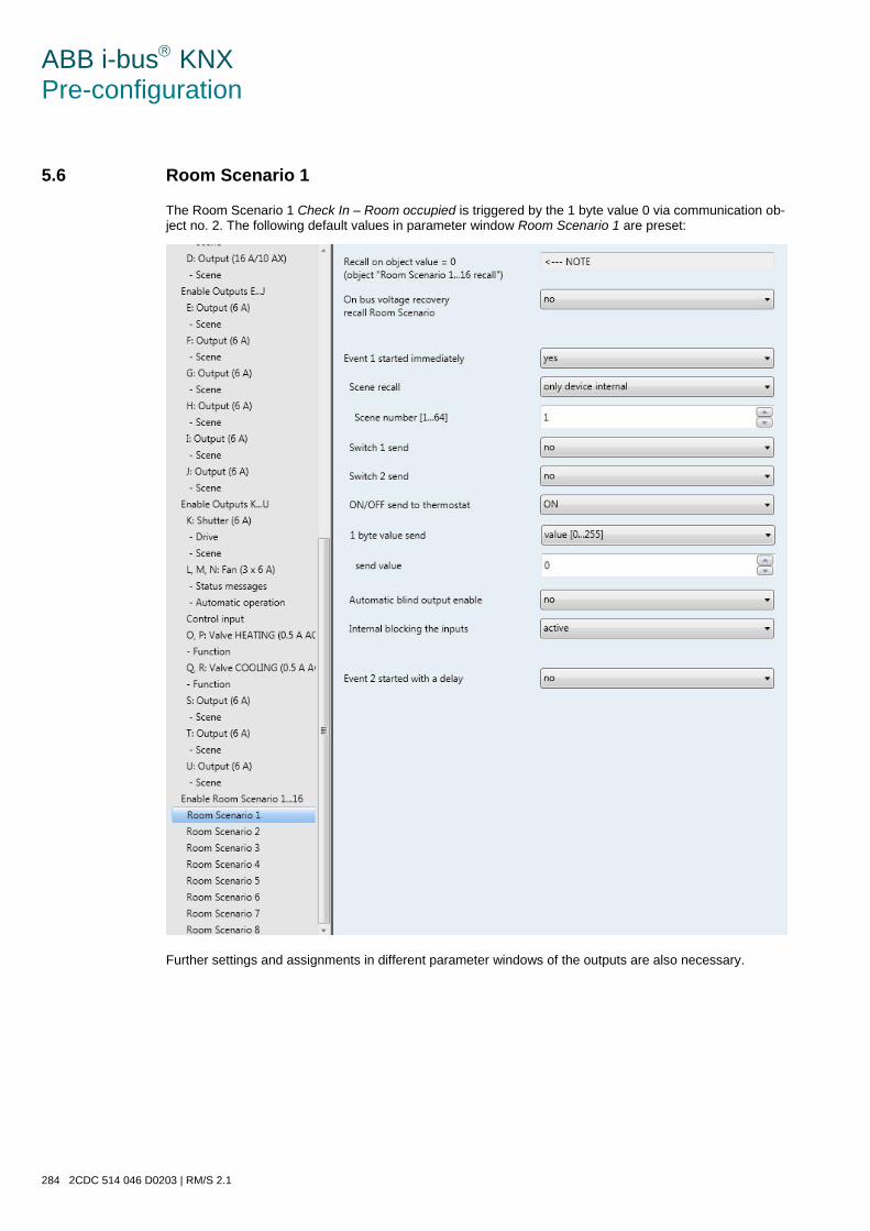
ABB i-bus KNX Pre-configuration
284 2CDC 514 046 D0203 | RM/S 2.1
5.6 Room Scenario 1
The Room Scenario 1 Check In – Room occupied is triggered by the 1 byte value 0 via communication ob-ject no. 2. The following default values in parameter window Room Scenario 1 are preset:
Further settings and assignments in different parameter windows of the outputs are also necessary.

ABB i-bus KNX Pre-configuration
RM/S 2.1 | 2CDC 514 046 D0203 285
The following table includes an overview of these preconfigured settings:
Outputs
Parameter window Scene of the individual outputs
No scene assigned => unchanged Standard value Assignment to scene number
A: Socket switched OFF 1
B: Floor or desk light socket ON 1
C: Bathroom fan OFF 1
D: Auxiliary electrical heater OFF 1
E: Bedside left OFF 1
F: Bedside right OFF 1
G: Main room 1 OFF 1
H: Main room 2 OFF 1
I: Hall ON 1
J: Bathroom OFF 1
K: Blind x
L, M, N: Fan Via control value of the RDF/A
O, P, Q, R: Valves
S: Do not disturb OFF 1
T: Room service OFF 1
U: Room occupied; Please wait OFF 1
Default setting of the standard value in the parameter windows of the outputs.
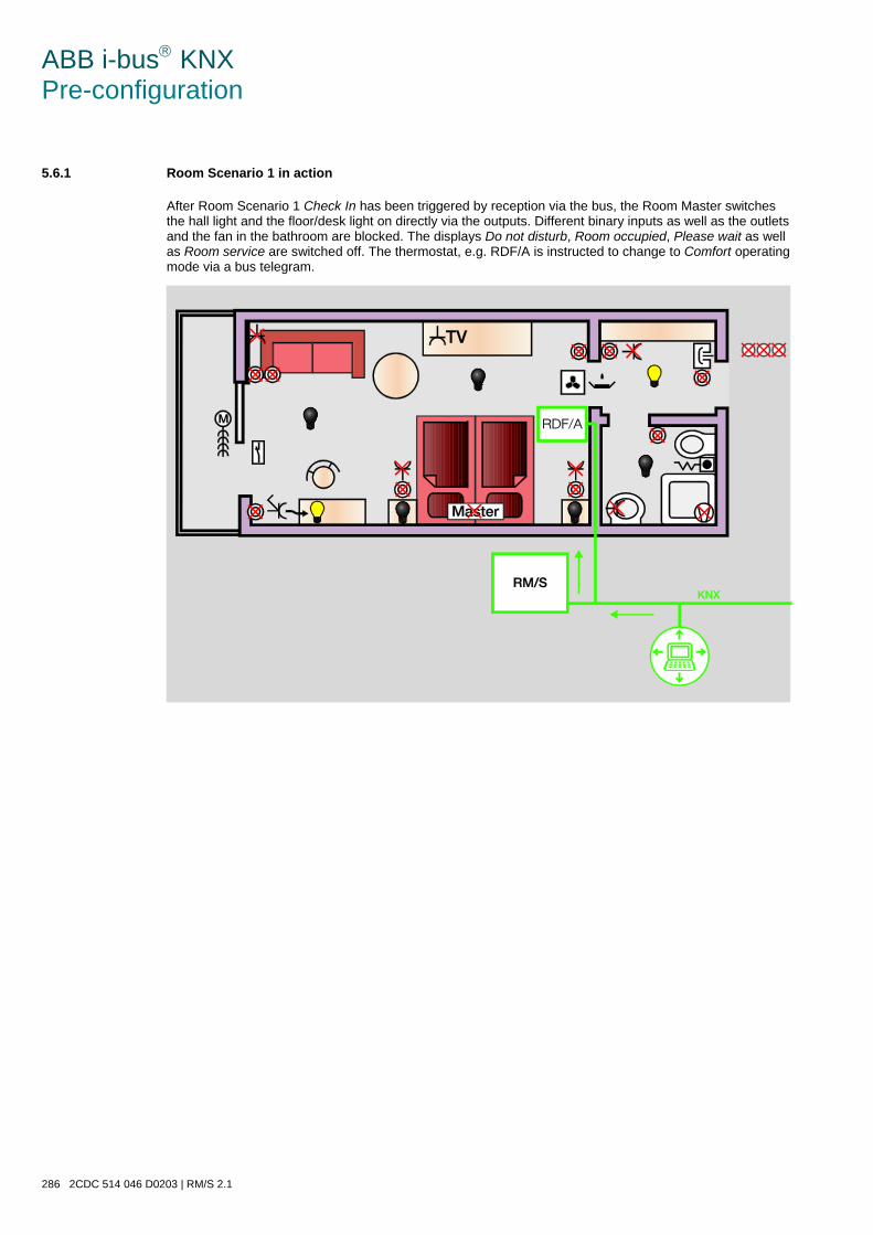
ABB i-bus KNX Pre-configuration
286 2CDC 514 046 D0203 | RM/S 2.1
5.6.1 Room Scenario 1 in action
After Room Scenario 1 Check In has been triggered by reception via the bus, the Room Master switches the hall light and the floor/desk light on directly via the outputs. Different binary inputs as well as the outlets and the fan in the bathroom are blocked. The displays Do not disturb, Room occupied, Please wait as well as Room service are switched off. The thermostat, e.g. RDF/A is instructed to change to Comfort operating mode via a bus telegram.

ABB i-bus KNX Pre-configuration
RM/S 2.1 | 2CDC 514 046 D0203 287
5.7 Room Scenario 2
The Room Scenario 2 Check Out – Room not occupied is triggered by the 1 byte value 1 via communica-tion object no. 2. The following default values in parameter window Room Scenario 2 are preset:
Further settings and assignments in different parameter windows of the outputs are also necessary.

ABB i-bus KNX Pre-configuration
288 2CDC 514 046 D0203 | RM/S 2.1
The following table includes an overview of these preconfigured settings:
Outputs
Parameter window Scene of the individual outputs
No scene assigned => unchanged Standard value Assignment to scene number
A: Socket switched OFF 2
B: Floor or desk light socket OFF 2
C: Bathroom fan OFF 2
D: Auxiliary electrical heater OFF 2
E: Bedside left OFF 2
F: Bedside right OFF 2
G: Main room 1 OFF 2
H: Main room 2 OFF 2
I: Hall OFF 2
J: Bathroom OFF 2
K: Blind Position 0 Slat 0
2
L, M, N: Fan Via control value of the RDF/A
O, P, Q, R: Valves
S: Do not disturb OFF 2
T: Room service ON 2
U: Room occupied; Please wait OFF 2
Default setting of the standard value in the parameter windows of the outputs.
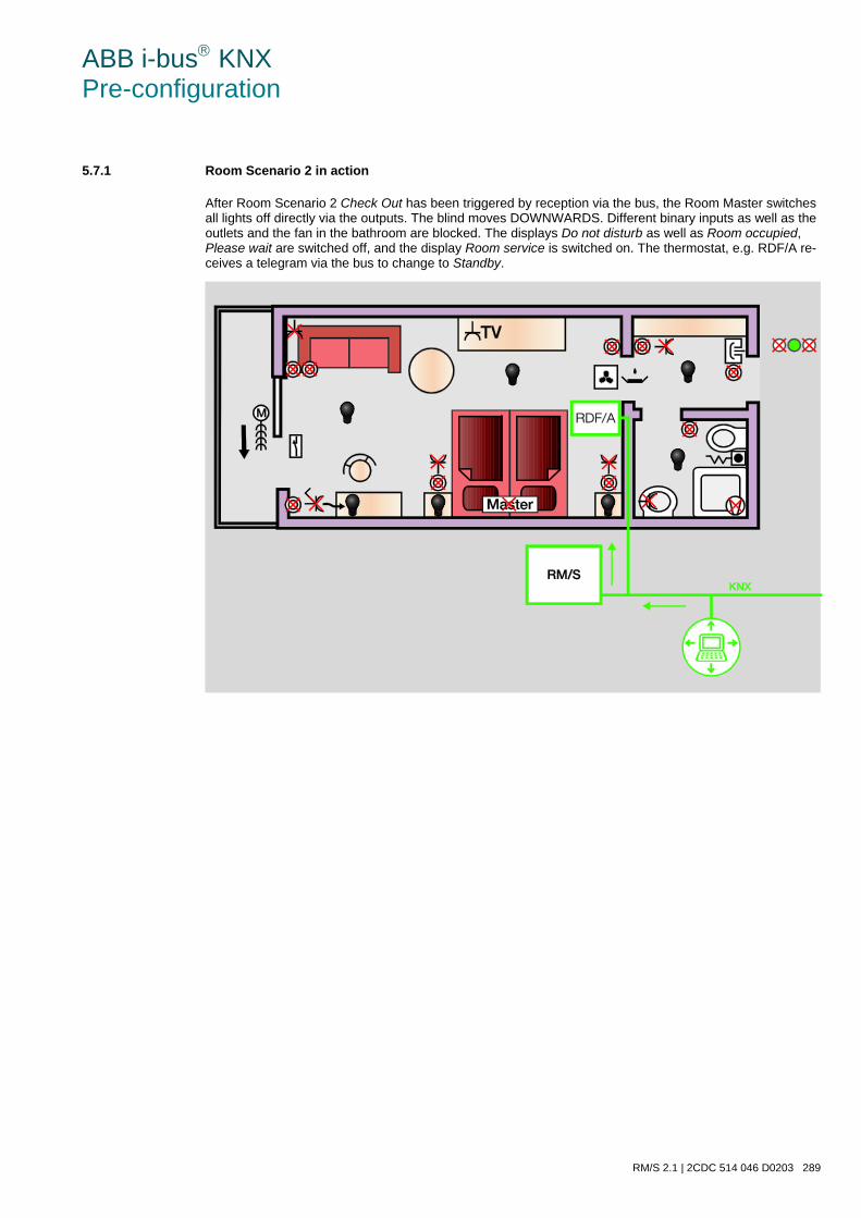
ABB i-bus KNX Pre-configuration
RM/S 2.1 | 2CDC 514 046 D0203 289
5.7.1 Room Scenario 2 in action
After Room Scenario 2 Check Out has been triggered by reception via the bus, the Room Master switches all lights off directly via the outputs. The blind moves DOWNWARDS. Different binary inputs as well as the outlets and the fan in the bathroom are blocked. The displays Do not disturb as well as Room occupied, Please wait are switched off, and the display Room service is switched on. The thermostat, e.g. RDF/A re-ceives a telegram via the bus to change to Standby.
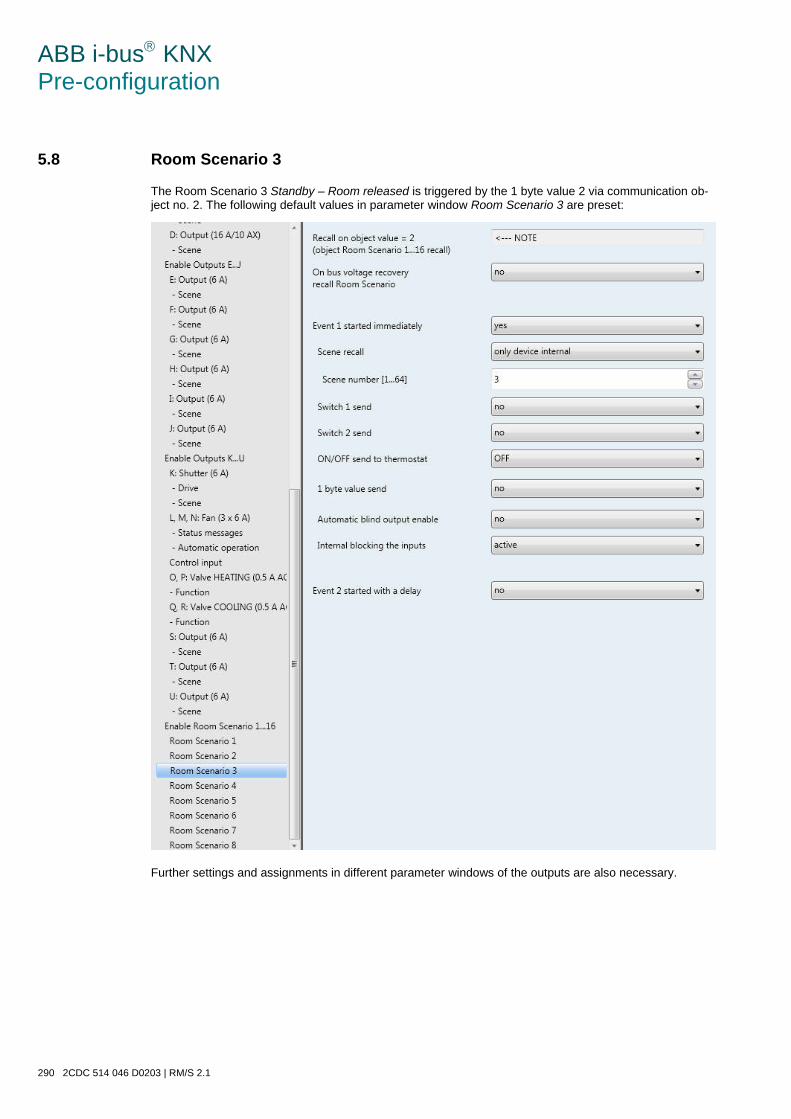
ABB i-bus KNX Pre-configuration
290 2CDC 514 046 D0203 | RM/S 2.1
5.8 Room Scenario 3
The Room Scenario 3 Standby – Room released is triggered by the 1 byte value 2 via communication ob-ject no. 2. The following default values in parameter window Room Scenario 3 are preset:
Further settings and assignments in different parameter windows of the outputs are also necessary.

ABB i-bus KNX Pre-configuration
RM/S 2.1 | 2CDC 514 046 D0203 291
The following table includes an overview of these preconfigured settings:
Outputs
Parameter window Scene of the individual outputs
No scene assigned => unchanged Standard value Assignment to scene number
A: Socket switched OFF 3
B: Floor or desk light socket OFF 3
C: Bathroom fan OFF 3
D: Auxiliary electrical heater OFF 3
E: Bedside left OFF 3
F: Bedside right OFF 3
G: Main room 1 OFF 3
H: Main room 2 OFF 3
I: Hall OFF 3
J: Bathroom OFF 3
K: Blind Position 100 Slat 100 3
L, M, N: Fan Via control value of the RDF/A
O, P, Q, R: Valves
S: Do not disturb OFF 3
T: Room service OFF 3
U: Room occupied; Please wait OFF 3
Default setting of the standard value in the parameter windows of the outputs.
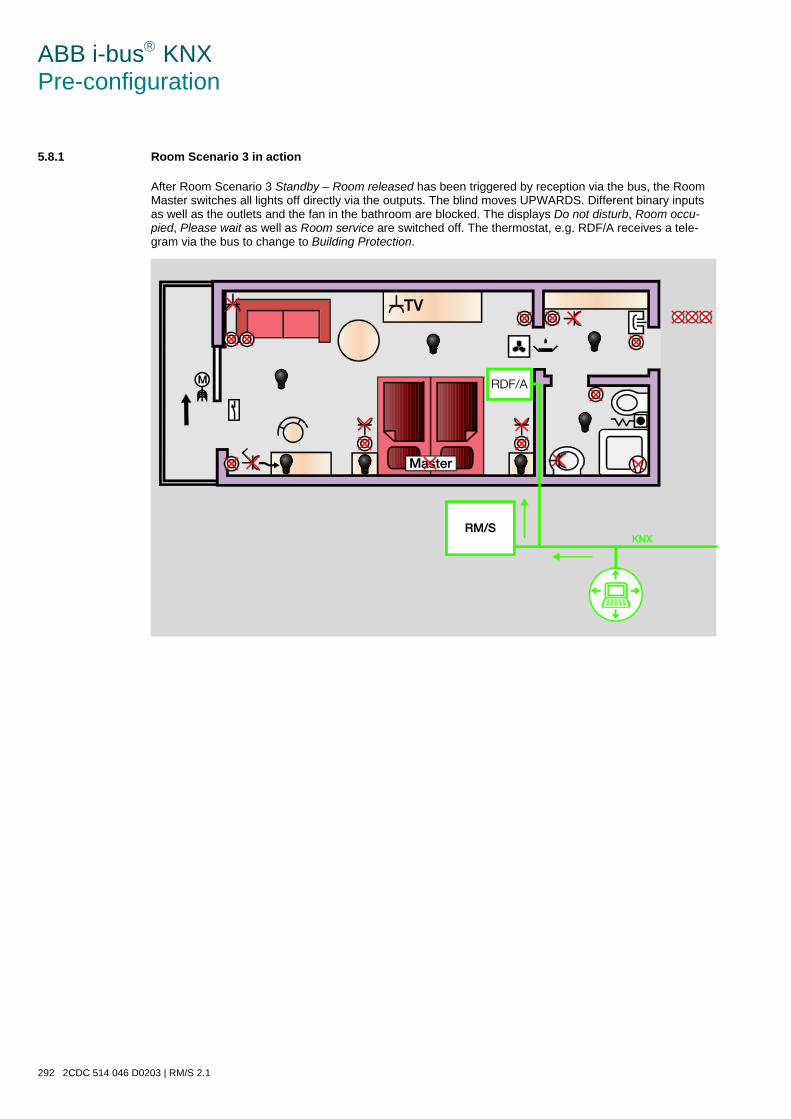
ABB i-bus KNX Pre-configuration
292 2CDC 514 046 D0203 | RM/S 2.1
5.8.1 Room Scenario 3 in action
After Room Scenario 3 Standby – Room released has been triggered by reception via the bus, the Room Master switches all lights off directly via the outputs. The blind moves UPWARDS. Different binary inputs as well as the outlets and the fan in the bathroom are blocked. The displays Do not disturb, Room occu-pied, Please wait as well as Room service are switched off. The thermostat, e.g. RDF/A receives a tele-gram via the bus to change to Building Protection.
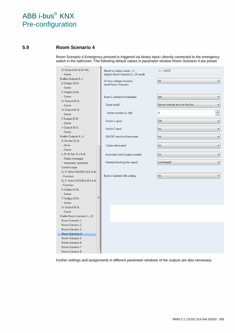
ABB i-bus KNX Pre-configuration
RM/S 2.1 | 2CDC 514 046 D0203 293
5.9 Room Scenario 4
Room Scenario 4 Emergency pressed is triggered via binary input i directly connected to the emergency switch in the bathroom. The following default values in parameter window Room Scenario 4 are preset:
Further settings and assignments in different parameter windows of the outputs are also necessary.

ABB i-bus KNX Pre-configuration
294 2CDC 514 046 D0203 | RM/S 2.1
The following table includes an overview of these preconfigured settings:
Outputs
Parameter window Scene of the individual outputs
No scene assigned => unchanged Standard value Assignment to scene number
A: Socket switched x
B: Floor or desk light socket ON 4
C: Bathroom fan x
D: Auxiliary electrical heater x
E: Bedside left x
F: Bedside right x
G: Main room 1 ON 4
H: Main room 2 ON 4
I: Hall ON 4
J: Bathroom ON 4
K: Blind x
L, M, N: Fan Via control value of the RDF/A
O, P, Q, R: Valves
S: Do not disturb OFF 4
T: Room service x
U: Room occupied; Please wait x
Default setting of the standard value in the parameter windows of the outputs.
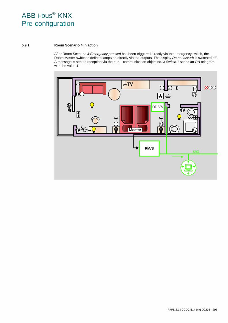
ABB i-bus KNX Pre-configuration
RM/S 2.1 | 2CDC 514 046 D0203 295
5.9.1 Room Scenario 4 in action
After Room Scenario 4 Emergency pressed has been triggered directly via the emergency switch, the Room Master switches defined lamps on directly via the outputs. The display Do not disturb is switched off. A message is sent to reception via the bus – communication object no. 3 Switch 1 sends an ON telegram with the value 1.
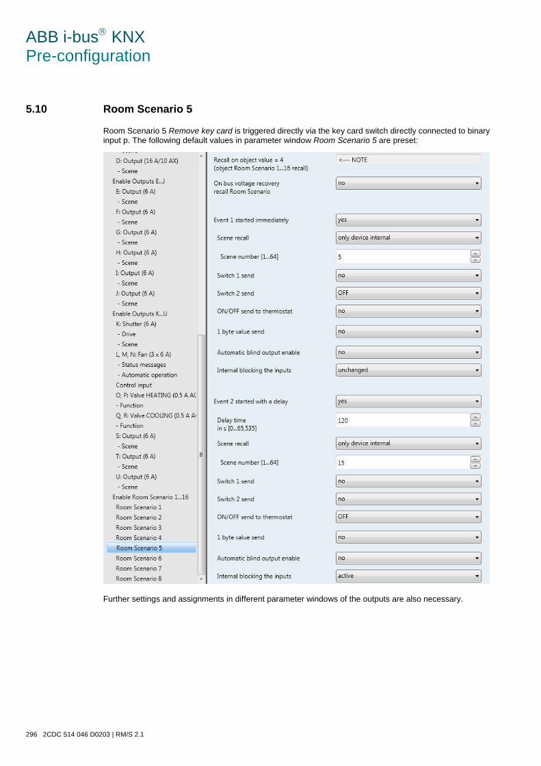
ABB i-bus KNX Pre-configuration
296 2CDC 514 046 D0203 | RM/S 2.1
5.10 Room Scenario 5
Room Scenario 5 Remove key card is triggered directly via the key card switch directly connected to binary input p. The following default values in parameter window Room Scenario 5 are preset:
Further settings and assignments in different parameter windows of the outputs are also necessary.
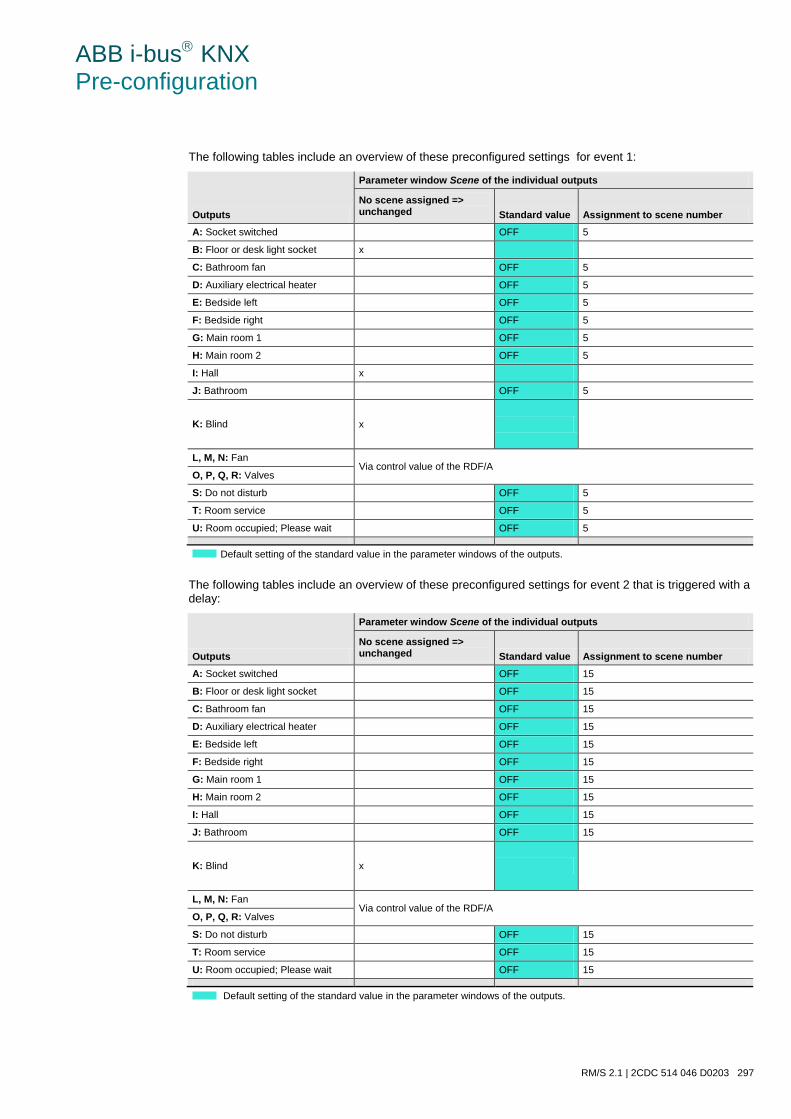
ABB i-bus KNX Pre-configuration
RM/S 2.1 | 2CDC 514 046 D0203 297
The following tables include an overview of these preconfigured settings for event 1:
Outputs
Parameter window Scene of the individual outputs
No scene assigned => unchanged Standard value Assignment to scene number
A: Socket switched OFF 5
B: Floor or desk light socket x
C: Bathroom fan OFF 5
D: Auxiliary electrical heater OFF 5
E: Bedside left OFF 5
F: Bedside right OFF 5
G: Main room 1 OFF 5
H: Main room 2 OFF 5
I: Hall x
J: Bathroom OFF 5
K: Blind x
L, M, N: Fan Via control value of the RDF/A
O, P, Q, R: Valves
S: Do not disturb OFF 5
T: Room service OFF 5
U: Room occupied; Please wait OFF 5
Default setting of the standard value in the parameter windows of the outputs.
The following tables include an overview of these preconfigured settings for event 2 that is triggered with a delay:
Outputs
Parameter window Scene of the individual outputs
No scene assigned => unchanged Standard value Assignment to scene number
A: Socket switched OFF 15
B: Floor or desk light socket OFF 15
C: Bathroom fan OFF 15
D: Auxiliary electrical heater OFF 15
E: Bedside left OFF 15
F: Bedside right OFF 15
G: Main room 1 OFF 15
H: Main room 2 OFF 15
I: Hall OFF 15
J: Bathroom OFF 15
K: Blind x
L, M, N: Fan Via control value of the RDF/A
O, P, Q, R: Valves
S: Do not disturb OFF 15
T: Room service OFF 15
U: Room occupied; Please wait OFF 15
Default setting of the standard value in the parameter windows of the outputs.
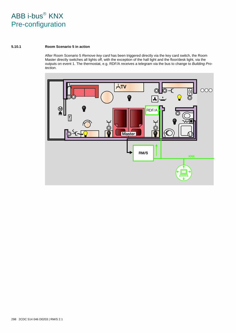
ABB i-bus KNX Pre-configuration
298 2CDC 514 046 D0203 | RM/S 2.1
5.10.1 Room Scenario 5 in action
After Room Scenario 5 Remove key card has been triggered directly via the key card switch, the Room Master directly switches all lights off, with the exception of the hall light and the floor/desk light, via the outputs on event 1. The thermostat, e.g. RDF/A receives a telegram via the bus to change to Building Pro-tection.
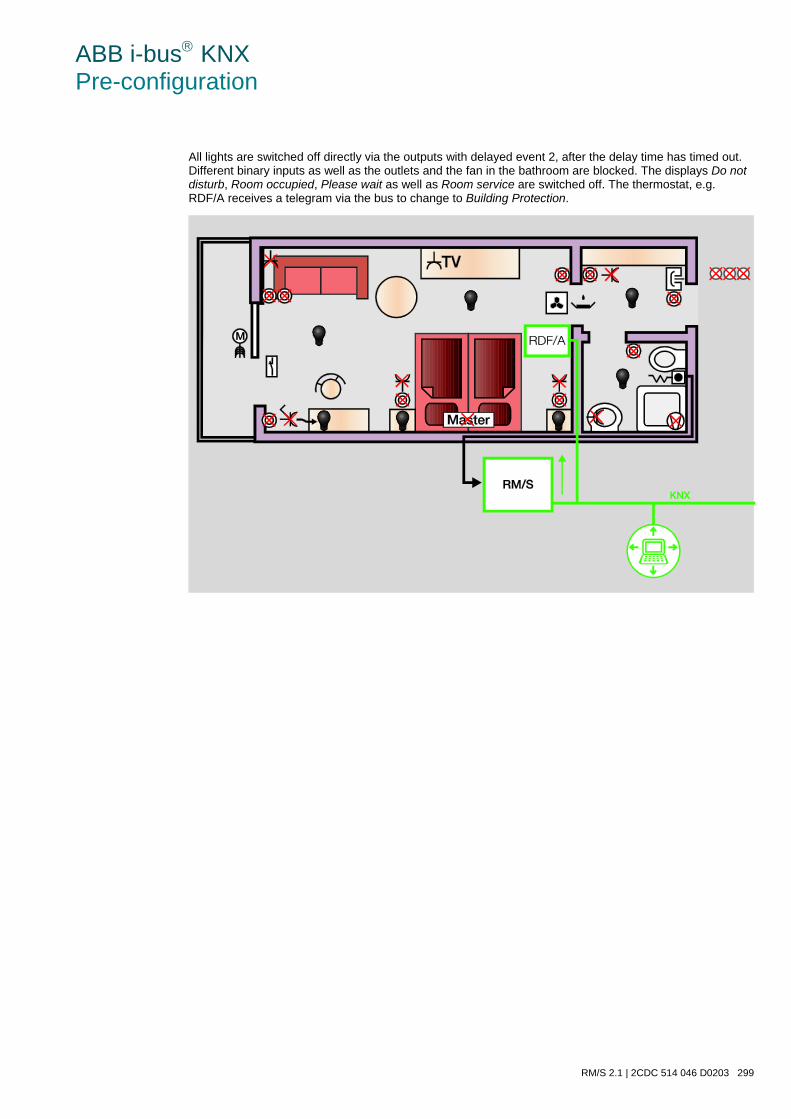
ABB i-bus KNX Pre-configuration
RM/S 2.1 | 2CDC 514 046 D0203 299
All lights are switched off directly via the outputs with delayed event 2, after the delay time has timed out. Different binary inputs as well as the outlets and the fan in the bathroom are blocked. The displays Do not disturb, Room occupied, Please wait as well as Room service are switched off. The thermostat, e.g. RDF/A receives a telegram via the bus to change to Building Protection.
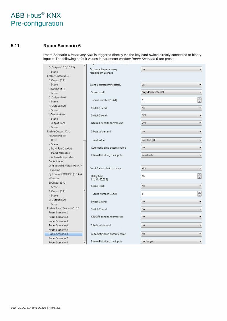
ABB i-bus KNX Pre-configuration
300 2CDC 514 046 D0203 | RM/S 2.1
5.11 Room Scenario 6
Room Scenario 6 Insert key card is triggered directly via the key card switch directly connected to binary input p. The following default values in parameter window Room Scenario 6 are preset:
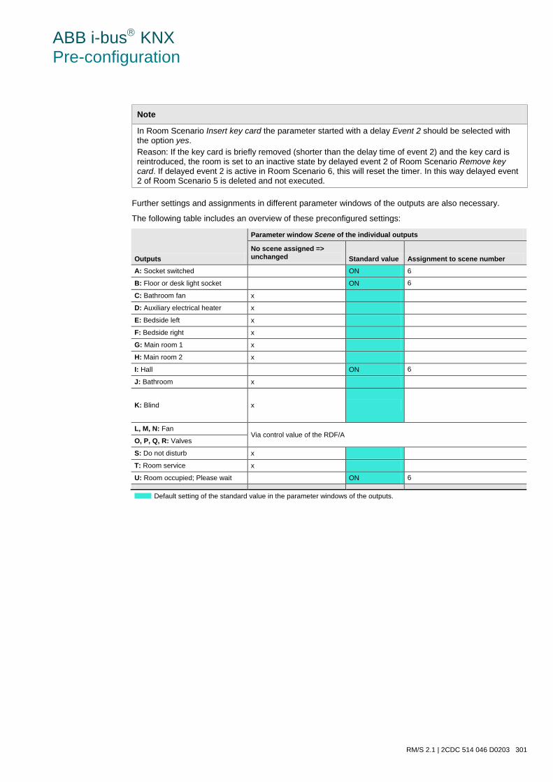
ABB i-bus KNX Pre-configuration
RM/S 2.1 | 2CDC 514 046 D0203 301
Note
In Room Scenario Insert key card the parameter started with a delay Event 2 should be selected with the option yes. Reason: If the key card is briefly removed (shorter than the delay time of event 2) and the key card is reintroduced, the room is set to an inactive state by delayed event 2 of Room Scenario Remove key card. If delayed event 2 is active in Room Scenario 6, this will reset the timer. In this way delayed event 2 of Room Scenario 5 is deleted and not executed.
Further settings and assignments in different parameter windows of the outputs are also necessary.
The following table includes an overview of these preconfigured settings:
Outputs
Parameter window Scene of the individual outputs
No scene assigned => unchanged Standard value Assignment to scene number
A: Socket switched ON 6
B: Floor or desk light socket ON 6
C: Bathroom fan x
D: Auxiliary electrical heater x
E: Bedside left x
F: Bedside right x
G: Main room 1 x
H: Main room 2 x
I: Hall ON 6
J: Bathroom x
K: Blind x
L, M, N: Fan Via control value of the RDF/A
O, P, Q, R: Valves
S: Do not disturb x
T: Room service x
U: Room occupied; Please wait ON 6
Default setting of the standard value in the parameter windows of the outputs.

ABB i-bus KNX Pre-configuration
302 2CDC 514 046 D0203 | RM/S 2.1
5.11.1 Room Scenario 6 in action
After Room Scenario 6 Insert key card has been triggered by the key card switch, the Room Master switches the hall light and the floor/desk light on directly via the outputs. The display Room occupied, Please wait is switched on. The thermostat, e.g. RDF/A receives a telegram via the bus to change to Com-fort.
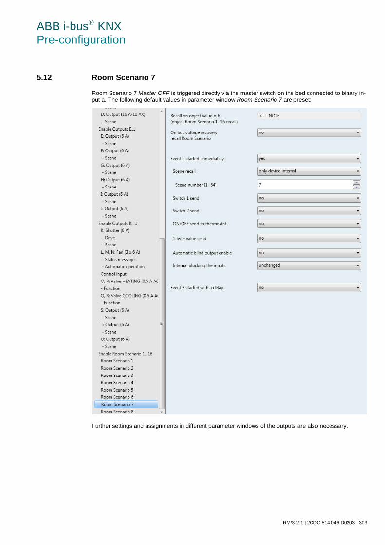
ABB i-bus KNX Pre-configuration
RM/S 2.1 | 2CDC 514 046 D0203 303
5.12 Room Scenario 7
Room Scenario 7 Master OFF is triggered directly via the master switch on the bed connected to binary in-put a. The following default values in parameter window Room Scenario 7 are preset:
Further settings and assignments in different parameter windows of the outputs are also necessary.
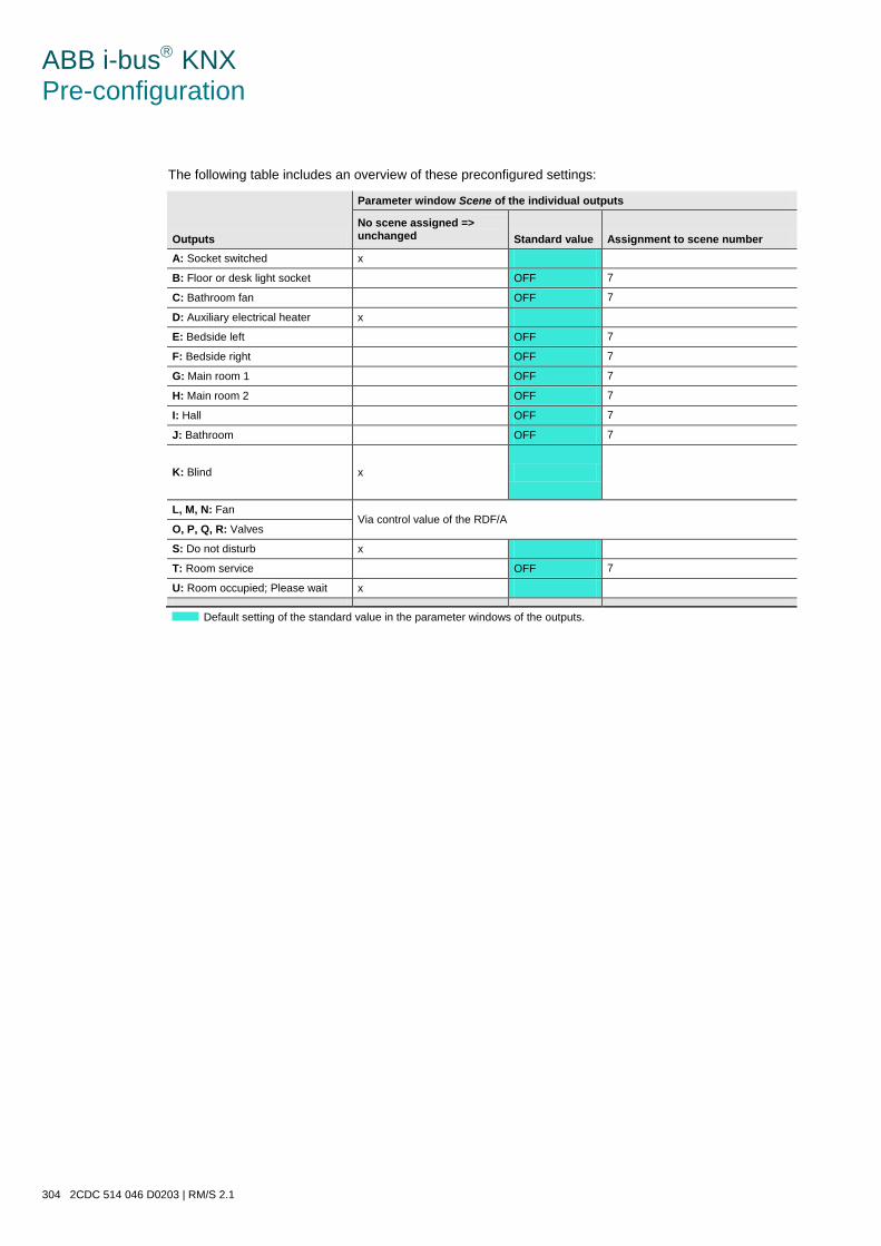
ABB i-bus KNX Pre-configuration
304 2CDC 514 046 D0203 | RM/S 2.1
The following table includes an overview of these preconfigured settings:
Outputs
Parameter window Scene of the individual outputs
No scene assigned => unchanged Standard value Assignment to scene number
A: Socket switched x
B: Floor or desk light socket OFF 7
C: Bathroom fan OFF 7
D: Auxiliary electrical heater x
E: Bedside left OFF 7
F: Bedside right OFF 7
G: Main room 1 OFF 7
H: Main room 2 OFF 7
I: Hall OFF 7
J: Bathroom OFF 7
K: Blind x
L, M, N: Fan Via control value of the RDF/A
O, P, Q, R: Valves
S: Do not disturb x
T: Room service OFF 7
U: Room occupied; Please wait x
Default setting of the standard value in the parameter windows of the outputs.
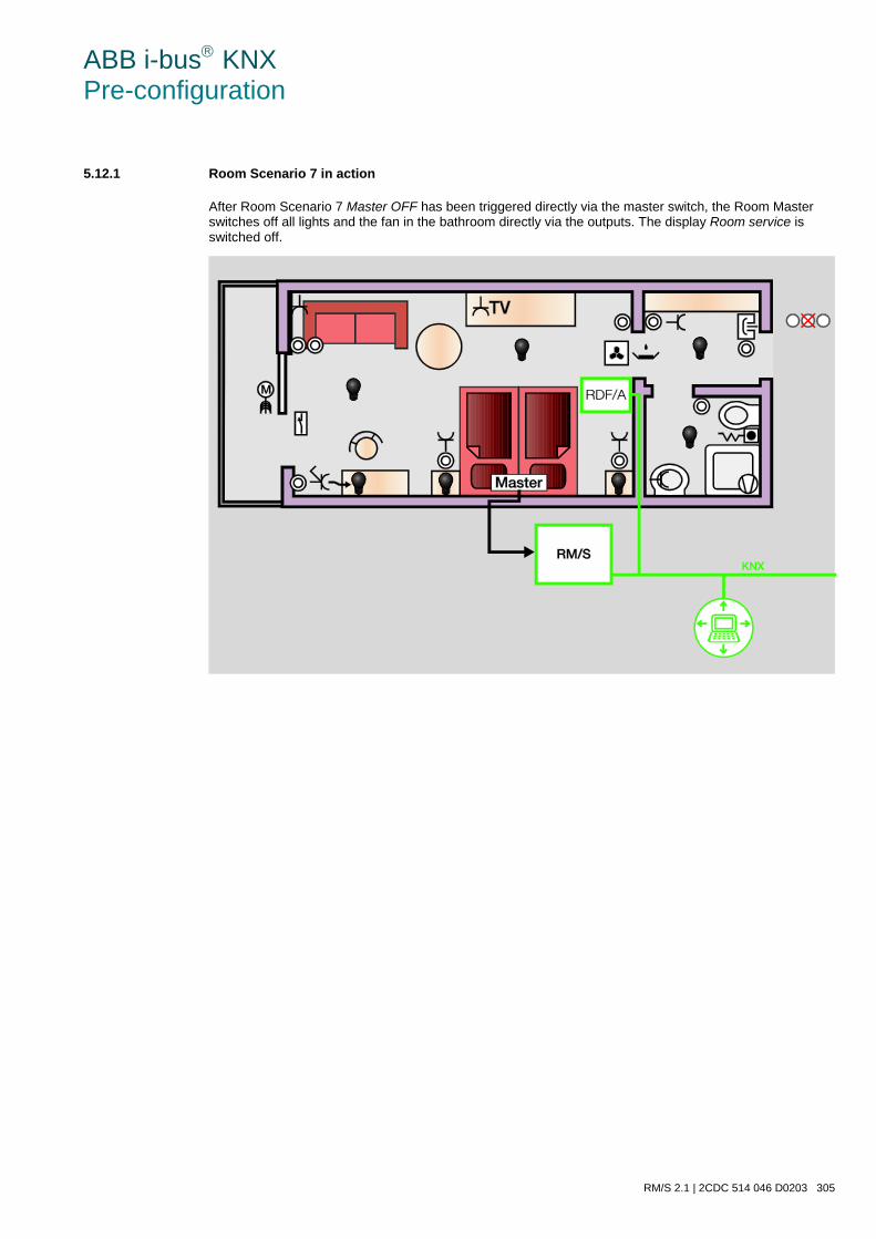
ABB i-bus KNX Pre-configuration
RM/S 2.1 | 2CDC 514 046 D0203 305
5.12.1 Room Scenario 7 in action
After Room Scenario 7 Master OFF has been triggered directly via the master switch, the Room Master switches off all lights and the fan in the bathroom directly via the outputs. The display Room service is switched off.
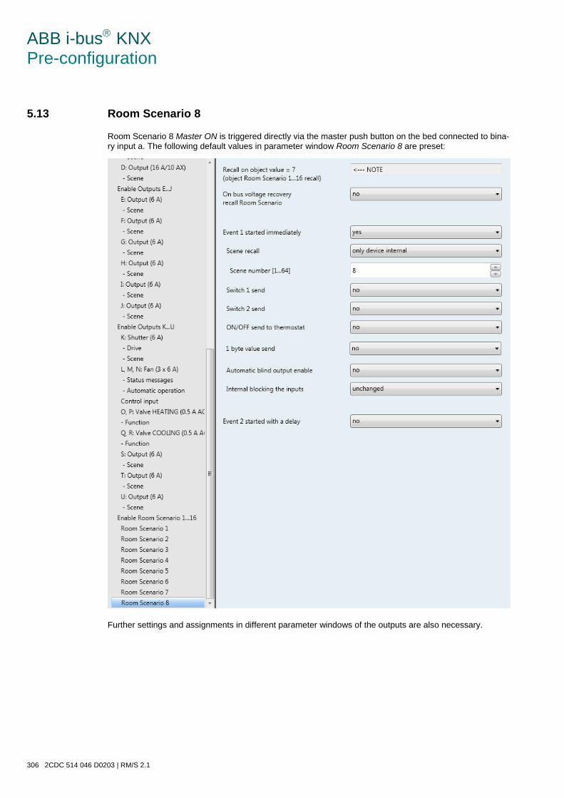
ABB i-bus KNX Pre-configuration
306 2CDC 514 046 D0203 | RM/S 2.1
5.13 Room Scenario 8
Room Scenario 8 Master ON is triggered directly via the master push button on the bed connected to bina-ry input a. The following default values in parameter window Room Scenario 8 are preset:
Further settings and assignments in different parameter windows of the outputs are also necessary.
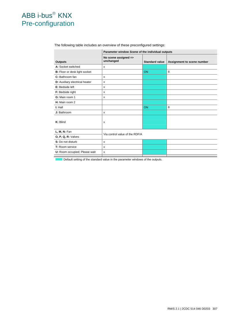
ABB i-bus KNX Pre-configuration
RM/S 2.1 | 2CDC 514 046 D0203 307
The following table includes an overview of these preconfigured settings:
Outputs
Parameter window Scene of the individual outputs
No scene assigned => unchanged Standard value Assignment to scene number
A: Socket switched x
B: Floor or desk light socket ON 8
C: Bathroom fan x
D: Auxiliary electrical heater x
E: Bedside left x
F: Bedside right x
G: Main room 1 x
H: Main room 2
I: Hall ON 8
J: Bathroom x
K: Blind x
L, M, N: Fan Via control value of the RDF/A
O, P, Q, R: Valves
S: Do not disturb x
T: Room service x
U: Room occupied; Please wait x
Default setting of the standard value in the parameter windows of the outputs.
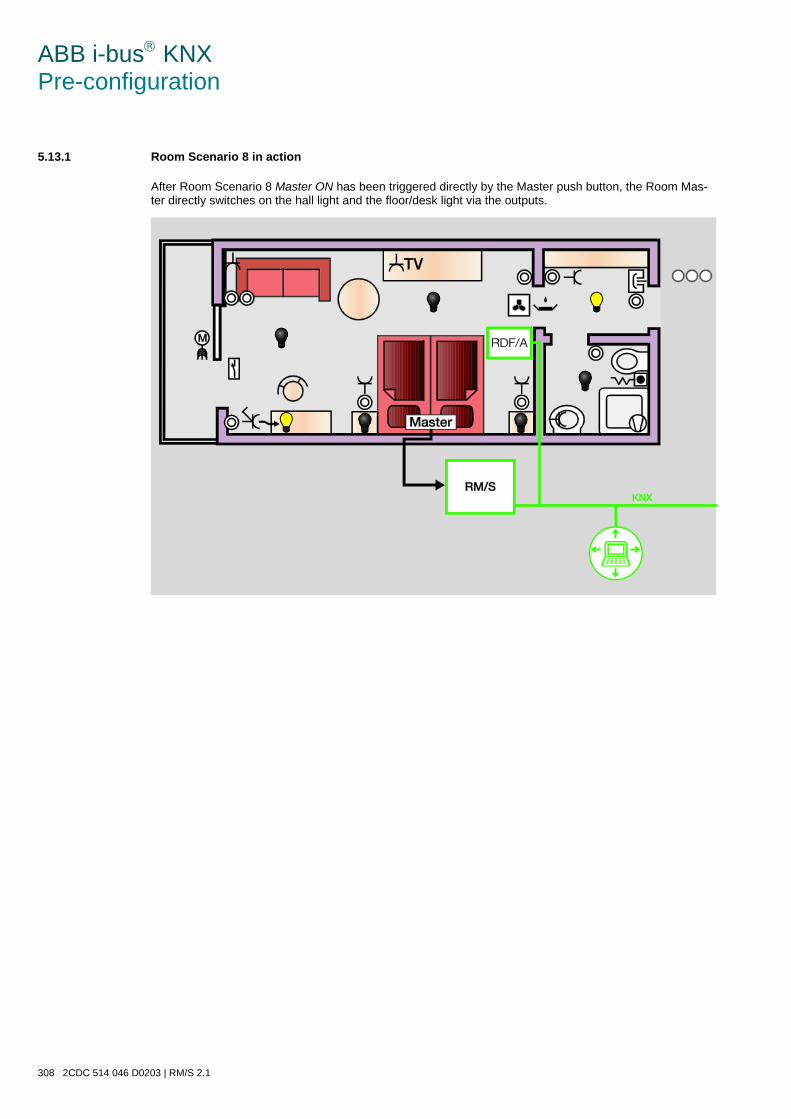
ABB i-bus KNX Pre-configuration
308 2CDC 514 046 D0203 | RM/S 2.1
5.13.1 Room Scenario 8 in action
After Room Scenario 8 Master ON has been triggered directly by the Master push button, the Room Mas-ter directly switches on the hall light and the floor/desk light via the outputs.
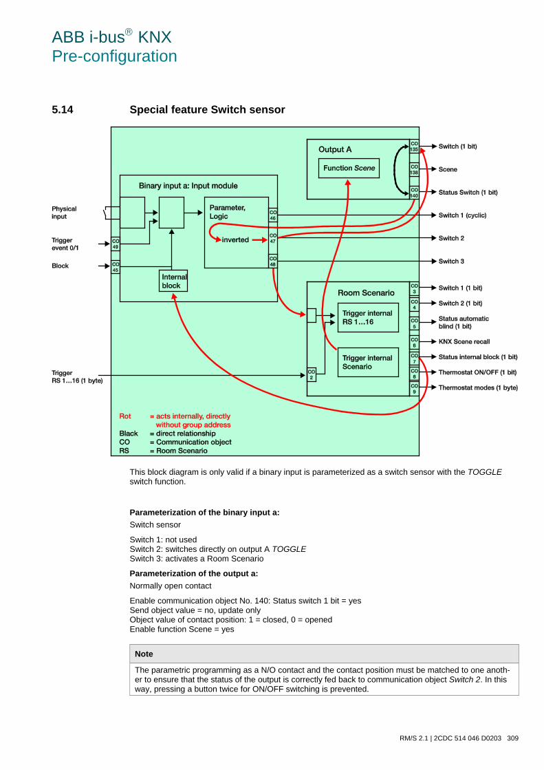
ABB i-bus KNX Pre-configuration
RM/S 2.1 | 2CDC 514 046 D0203 309
5.14 Special feature Switch sensor
This block diagram is only valid if a binary input is parameterized as a switch sensor with the TOGGLE switch function.
Parameterization of the binary input a: Switch sensor
Switch 1: not used Switch 2: switches directly on output A TOGGLE Switch 3: activates a Room Scenario
Parameterization of the output a: Normally open contact
Enable communication object No. 140: Status switch 1 bit = yes Send object value = no, update only Object value of contact position: 1 = closed, 0 = opened Enable function Scene = yes
Note
The parametric programming as a N/O contact and the contact position must be matched to one anoth-er to ensure that the status of the output is correctly fed back to communication object Switch 2. In this way, pressing a button twice for ON/OFF switching is prevented.
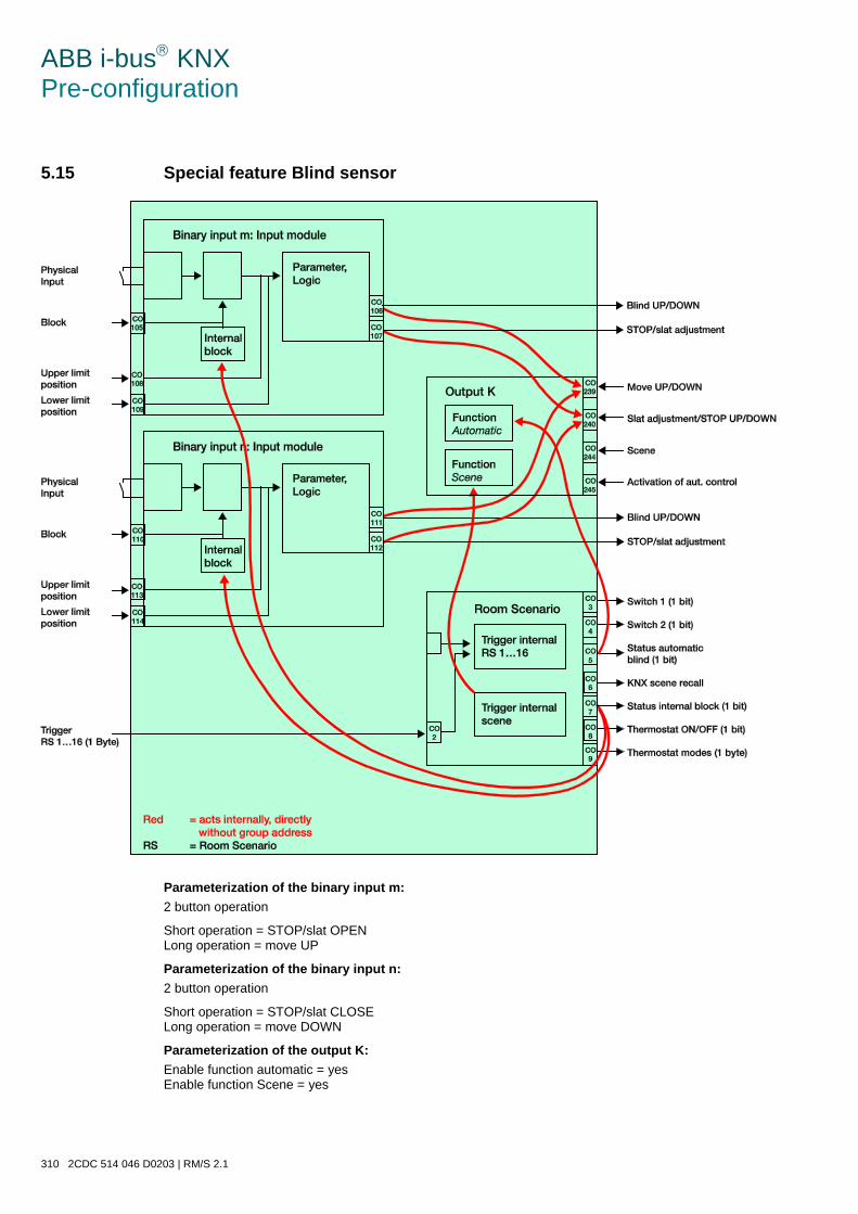
ABB i-bus KNX Pre-configuration
310 2CDC 514 046 D0203 | RM/S 2.1
5.15 Special feature Blind sensor
Parameterization of the binary input m: 2 button operation
Short operation = STOP/slat OPEN Long operation = move UP
Parameterization of the binary input n: 2 button operation
Short operation = STOP/slat CLOSE Long operation = move DOWN
Parameterization of the output K: Enable function automatic = yes Enable function Scene = yes
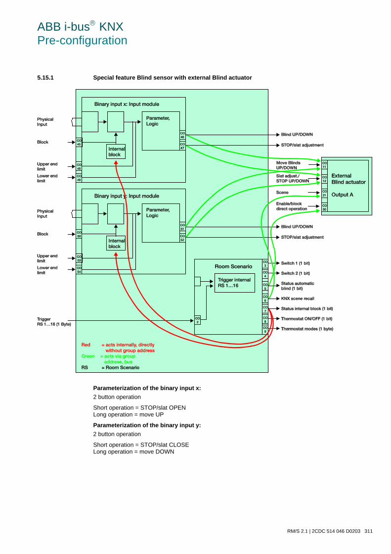
ABB i-bus KNX Pre-configuration
RM/S 2.1 | 2CDC 514 046 D0203 311
5.15.1 Special feature Blind sensor with external Blind actuator
Parameterization of the binary input x: 2 button operation
Short operation = STOP/slat OPEN Long operation = move UP
Parameterization of the binary input y: 2 button operation
Short operation = STOP/slat CLOSE Long operation = move DOWN
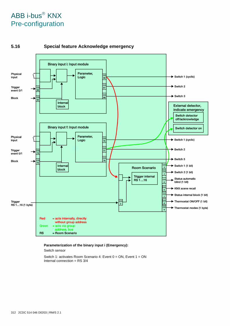
ABB i-bus KNX Pre-configuration
312 2CDC 514 046 D0203 | RM/S 2.1
5.16 Special feature Acknowledge emergency
Parameterization of the binary input i (Emergency): Switch sensor
Switch 1: activates Room Scenario 4: Event 0 = ON, Event 1 = ON Internal connection = RS 3/4
ABB i-bus KNX Pre-configuration
RM/S 2.1 | 2CDC 514 046 D0203 313
Parameterization of the binary input f (Hall light): Switch sensor
Distinction between short and long operation = yes Long operation from... = 1 s
Switch 1: switches directly on output I TOGGLE Event 0 = TOGGLE; Event 1 = no reaction Internal connection = output I (6 A)
Switch 2: resets the detector and switches output T OFF Event 0 = no reaction Event 1 = OFF Internal connection = output T (6 A)
Emergency call function: If the emergency signal is triggered via a pull cord in the bathroom, Room Scenario 4 is set. An external signalling device is actuated by function Switch 1. By an extended actuation of the push button in the hall (input f), the emergency call is acknowledged and the signalling device is reset.
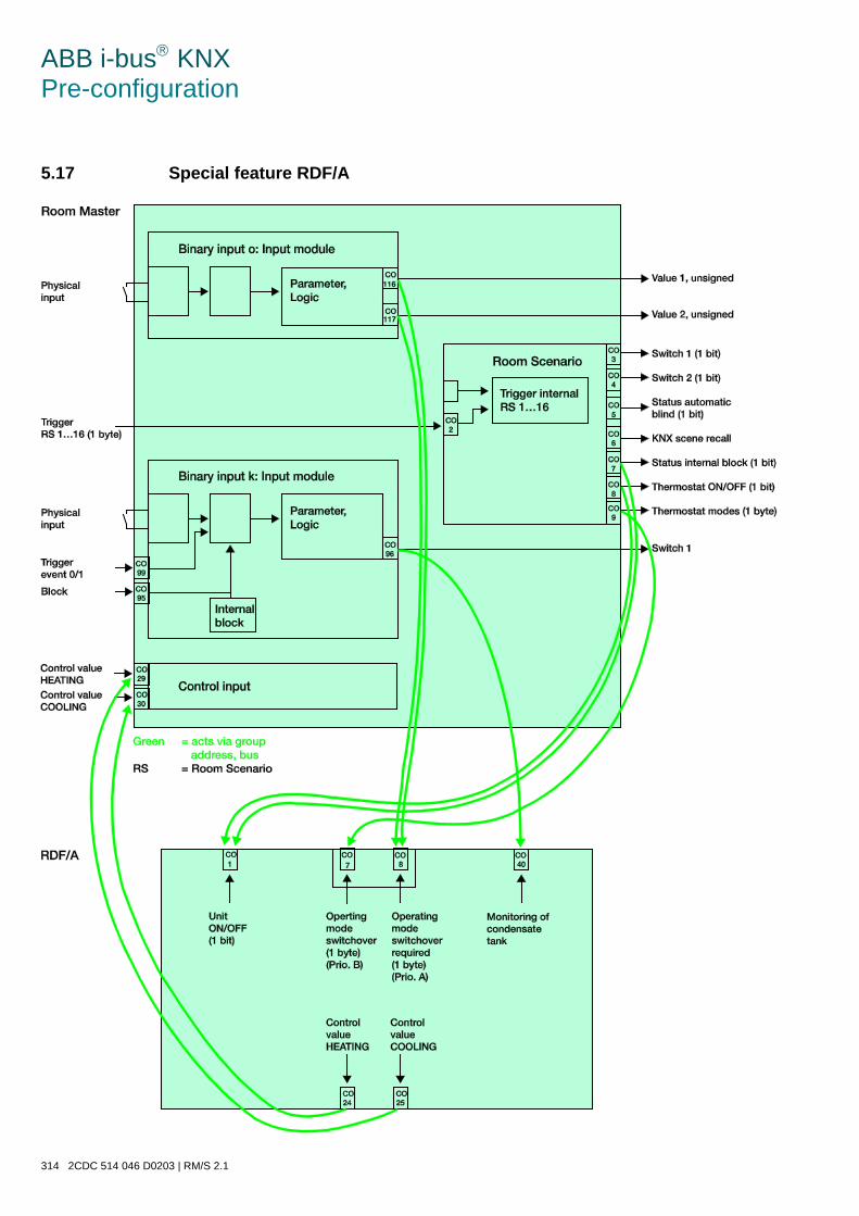
ABB i-bus KNX Pre-configuration
314 2CDC 514 046 D0203 | RM/S 2.1
5.17 Special feature RDF/A
ABB i-bus KNX Pre-configuration
RM/S 2.1 | 2CDC 514 046 D0203 315
The room states set the RDF/A! The RDF/A sets the Room Master!
Note
The fan limitation must be set to same in both devices!
Parameterization of the binary input o (Window contact): Value/Forced operation
Send value 1 [0…255]: 4 = Building Protection Send value 2 [0…255]: 0 = Automatic For further information see: Operating mode, page 165
Parameterization of the binary input k (Drip tray): Switch sensor
Signal condensate tank (drip tray): 0 = OFF, 1 = ON
Parameterization of the RDF/A: Switching the device On/Off: 0 = OFF, 1 = ON Toggling of operating mode = such as thermostat on RM/S (Prio. B) Toggling of operating mode forces = OMO as thermostat on RM/S (Prio. A) Monitoring of condensate tank: 0 = OFF, 1 = ON
Function of the RDF/A: Switching the control ON/OFF is the same as actuating the ON/OFF push button. OFF appears on the de-vice display when the device is switched off. The control setpoint is converted to a programmable tempera-ture setpoint value and the fan switches off immediately. Frost protection is activated internally. The but-tons can be operated. For further information see: Product manual RDF/A
ABB i-bus KNX Pre-configuration
316 2CDC 514 046 D0203 | RM/S 2.1
5.18 Special feature Push button in hall
Output I is switched on or switched off with every actuation of the push button in the hall. The room service personnel can switch off the Room service display (Output T) with a button push longer than 1s. If this op-tion is linked, for example, via a group address with the display at reception, they will be informed simulta-neously.
5.19 Special feature Push button do not disturb
Output S is switched on every time push button Do not disturb is pressed. By pushing the button for longer than 1s, the guest can switch off the display Do not disturb (Output S). The display Do not disturb (Output S) is switched off at the latest when the key card is removed and the guest leaves the room.
5.20 Special feature Push button room service
Output T is switched on every time the button Room service is pressed. By pushing the button for longer than 1s, the guest can switch off the display Room service (Output T). The display Room service (Output T) is switched off at the latest when the key card is removed and the guest leaves the room.
5.21 Special feature Bathroom fan
Output C is preconfigured with the function Staircase lighting. For this reason, the fan in the bathroom switches on directly with a button push for 300 seconds (5 minutes) and will switch off by itself, after the staircase lighting time has elapsed.
ABB i-bus KNX Appendix
RM/S 2.1 | 2CDC 514 046 D0203 317
A Appendix
A.1 Scope of delivery
The Room Master Premium is supplied together with the following components. The delivered items should be checked according to the following list.
• 1 pc. RM/S 2.1, Room Master Premium, MDRC
• 1 pc. Installation and operating instructions
• 1 pc. Bus connection terminal (red/black)
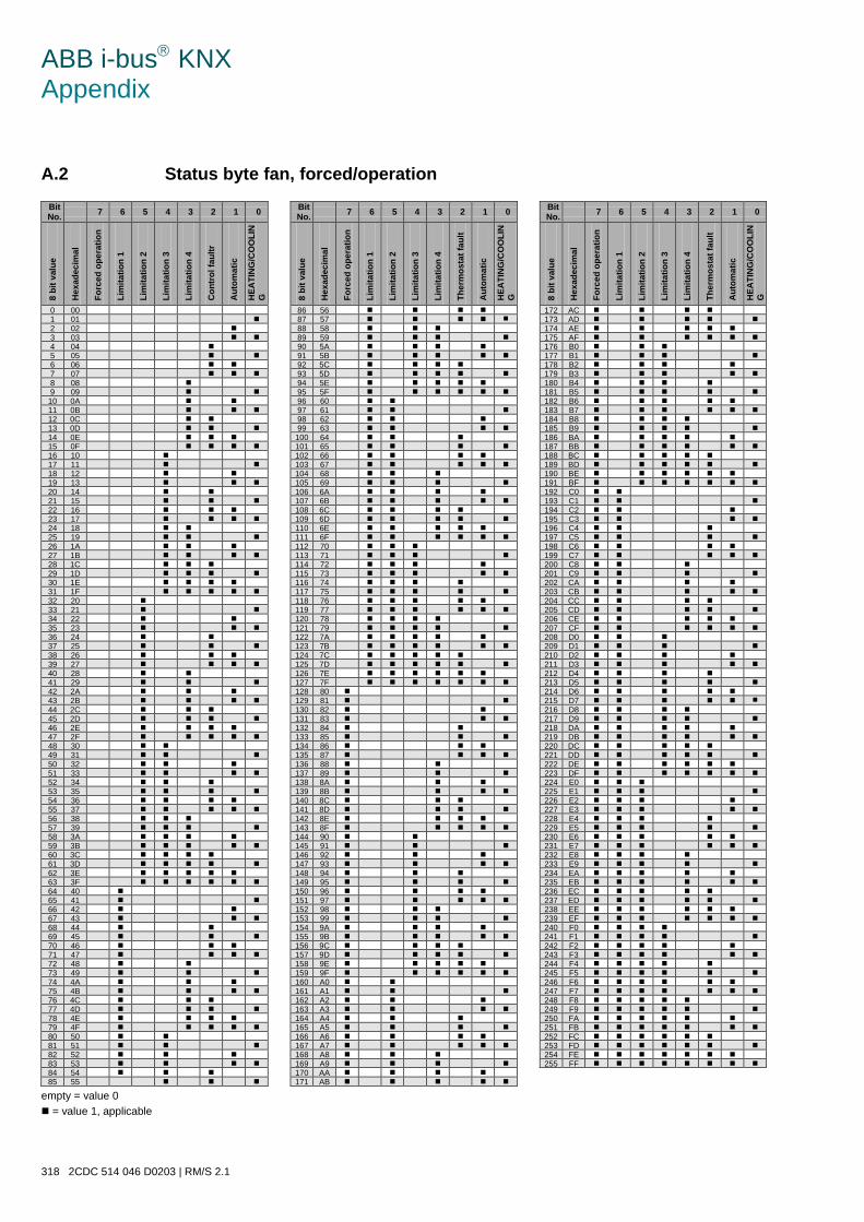
ABB i-bus KNX Appendix
318 2CDC 514 046 D0203 | RM/S 2.1
A.2 Status byte fan, forced/operation Bit No. 7 6 5 4 3 2 1 0 Bit
No. 7 6 5 4 3 2 1 0 Bit No. 7 6 5 4 3 2 1 0
8 bi
t val
ue
Hex
adec
imal
Forc
ed o
pera
tion
Lim
itatio
n 1
Lim
itatio
n 2
Lim
itatio
n 3
Lim
itatio
n 4
Con
trol
faul
tr
Aut
omat
ic
HEA
TIN
G/C
OO
LIN
G
8 bi
t val
ue
Hex
adec
imal
Forc
ed o
pera
tion
Lim
itatio
n 1
Lim
itatio
n 2
Lim
itatio
n 3
Lim
itatio
n 4
Ther
mos
tat f
ault
Aut
omat
ic
HEA
TIN
G/C
OO
LIN
G
8 bi
t val
ue
Hex
adec
imal
Forc
ed o
pera
tion
Lim
itatio
n 1
Lim
itatio
n 2
Lim
itatio
n 3
Lim
itatio
n 4
Ther
mos
tat f
ault
Aut
omat
ic
HEA
TIN
G/C
OO
LIN
G
0 00 86 56 172 AC 1 01 87 57 173 AD 2 02 88 58 174 AE 3 03 89 59 175 AF 4 04 90 5A 176 B0 5 05 91 5B 177 B1 6 06 92 5C 178 B2 7 07 93 5D 179 B3 8 08 94 5E 180 B4 9 09 95 5F 181 B5 10 0A 96 60 182 B6 11 0B 97 61 183 B7 12 0C 98 62 184 B8 13 0D 99 63 185 B9 14 0E 100 64 186 BA 15 0F 101 65 187 BB 16 10 102 66 188 BC 17 11 103 67 189 BD 18 12 104 68 190 BE 19 13 105 69 191 BF 20 14 106 6A 192 C0 21 15 107 6B 193 C1 22 16 108 6C 194 C2 23 17 109 6D 195 C3 24 18 110 6E 196 C4 25 19 111 6F 197 C5 26 1A 112 70 198 C6 27 1B 113 71 199 C7 28 1C 114 72 200 C8 29 1D 115 73 201 C9 30 1E 116 74 202 CA 31 1F 117 75 203 CB 32 20 118 76 204 CC 33 21 119 77 205 CD 34 22 120 78 206 CE 35 23 121 79 207 CF 36 24 122 7A 208 D0 37 25 123 7B 209 D1 38 26 124 7C 210 D2 39 27 125 7D 211 D3 40 28 126 7E 212 D4 41 29 127 7F 213 D5 42 2A 128 80 214 D6 43 2B 129 81 215 D7 44 2C 130 82 216 D8 45 2D 131 83 217 D9 46 2E 132 84 218 DA 47 2F 133 85 219 DB 48 30 134 86 220 DC 49 31 135 87 221 DD 50 32 136 88 222 DE 51 33 137 89 223 DF 52 34 138 8A 224 E0 53 35 139 8B 225 E1 54 36 140 8C 226 E2 55 37 141 8D 227 E3 56 38 142 8E 228 E4 57 39 143 8F 229 E5 58 3A 144 90 230 E6 59 3B 145 91 231 E7 60 3C 146 92 232 E8 61 3D 147 93 233 E9 62 3E 148 94 234 EA 63 3F 149 95 235 EB 64 40 150 96 236 EC 65 41 151 97 237 ED 66 42 152 98 238 EE 67 43 153 99 239 EF 68 44 154 9A 240 F0 69 45 155 9B 241 F1 70 46 156 9C 242 F2 71 47 157 9D 243 F3 72 48 158 9E 244 F4 73 49 159 9F 245 F5 74 4A 160 A0 246 F6 75 4B 161 A1 247 F7 76 4C 162 A2 248 F8 77 4D 163 A3 249 F9 78 4E 164 A4 250 FA 79 4F 165 A5 251 FB 80 50 166 A6 252 FC 81 51 167 A7 253 FD 82 52 168 A8 254 FE 83 53 169 A9 255 FF 84 54 170 AA 85 55
171 AB
empty = value 0 = value 1, applicable
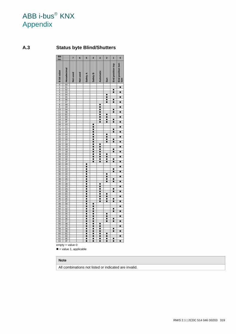
ABB i-bus KNX Appendix
RM/S 2.1 | 2CDC 514 046 D0203 319
A.3 Status byte Blind/Shutters Bit no. 7 6 5 4 3 2 1 0
B b
it va
lue
Hex
adec
imal
Not
use
d
Not
use
d
Safe
ty A
Safe
ty B
Aut
omat
ic
Sun
End
posi
tion
top
End
posi
tion
bot-
tom
0 00 1 01 2 02 3 03 4 04 5 05 6 06 7 07 8 08 9 09
10 0A 11 0B 12 0C 13 0D 14 0E 15 0F 16 10 17 11 18 12 19 13 20 14 21 15 22 16 23 17 24 18 25 19 26 1A 27 1B 28 1C 29 1D 30 1E 31 1F 32 20 33 21 34 22 35 23 36 24 37 25 38 26 39 27 40 28 41 29 42 2A 43 2B 44 2C 45 2D 46 2E 47 2F 48 30 49 31 50 32 51 33 52 34 53 35 54 36 55 37 56 38 57 39 58 3A 59 3B 60 3C 61 3D 62 3E 63 3F
empty = value 0 = value 1, applicable
Note
All combinations not listed or indicated are invalid.
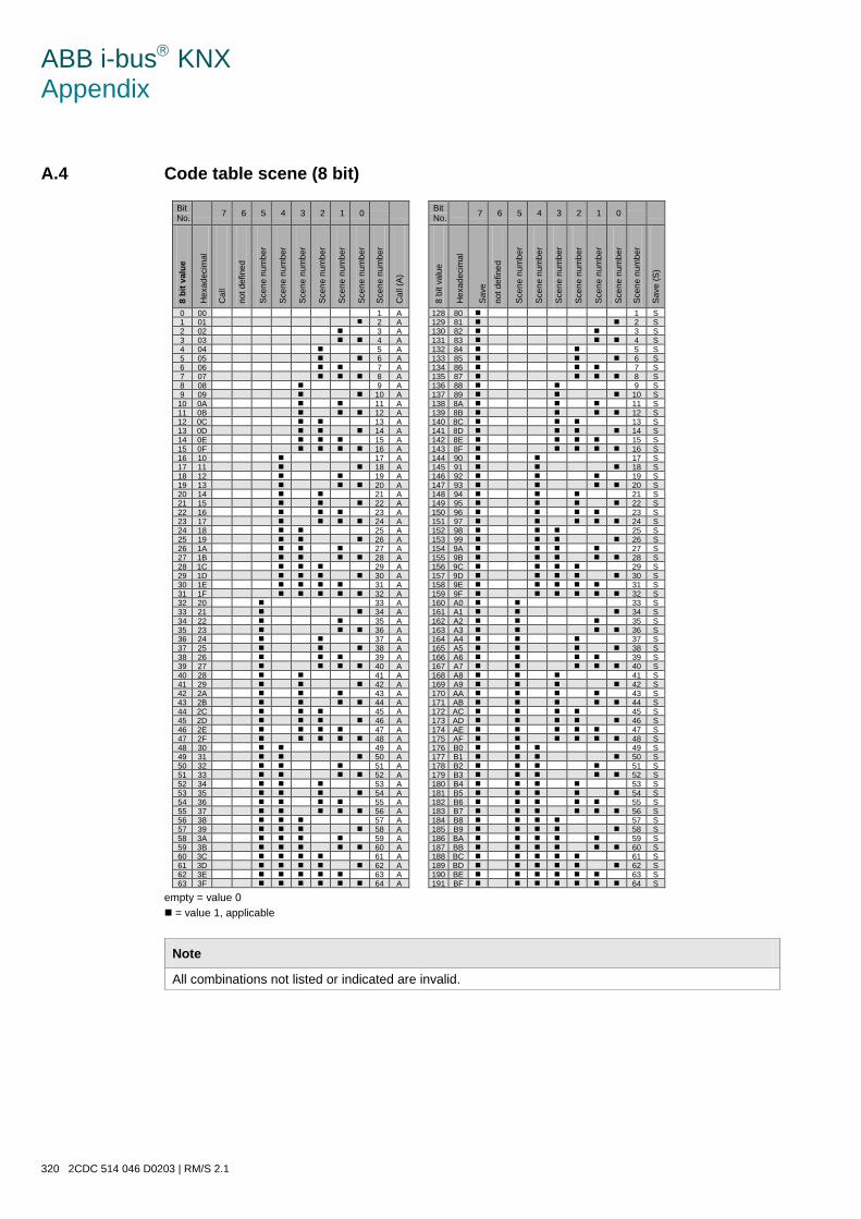
ABB i-bus KNX Appendix
320 2CDC 514 046 D0203 | RM/S 2.1
A.4 Code table scene (8 bit)
Bit No. 7 6 5 4 3 2 1 0
Bit No. 7 6 5 4 3 2 1 0
8 bi
t val
ue
Hex
adec
imal
Cal
l
not d
efin
ed
Sce
ne n
umbe
r
Sce
ne n
umbe
r
Sce
ne n
umbe
r
Sce
ne n
umbe
r
Sce
ne n
umbe
r
Sce
ne n
umbe
r
Sce
ne n
umbe
r
Cal
l (A
)
8 bi
t val
ue
Hex
adec
imal
S
ave
not d
efin
ed
Sce
ne n
umbe
r
Sce
ne n
umbe
r
Sce
ne n
umbe
r
Sce
ne n
umbe
r
Sce
ne n
umbe
r
Sce
ne n
umbe
r
Sce
ne n
umbe
r
Sav
e (S
)
0 00 1 A 128 80 1 S 1 01 2 A 129 81 2 S 2 02 3 A 130 82 3 S 3 03 4 A 131 83 4 S 4 04 5 A 132 84 5 S 5 05 6 A 133 85 6 S 6 06 7 A 134 86 7 S 7 07 8 A 135 87 8 S 8 08 9 A 136 88 9 S 9 09 10 A 137 89 10 S 10 0A 11 A 138 8A 11 S 11 0B 12 A 139 8B 12 S 12 0C 13 A 140 8C 13 S 13 0D 14 A 141 8D 14 S 14 0E 15 A 142 8E 15 S 15 0F 16 A 143 8F 16 S 16 10 17 A 144 90 17 S 17 11 18 A 145 91 18 S 18 12 19 A 146 92 19 S 19 13 20 A 147 93 20 S 20 14 21 A 148 94 21 S 21 15 22 A 149 95 22 S 22 16 23 A 150 96 23 S 23 17 24 A 151 97 24 S 24 18 25 A 152 98 25 S 25 19 26 A 153 99 26 S 26 1A 27 A 154 9A 27 S 27 1B 28 A 155 9B 28 S 28 1C 29 A 156 9C 29 S 29 1D 30 A 157 9D 30 S 30 1E 31 A 158 9E 31 S 31 1F 32 A 159 9F 32 S 32 20 33 A 160 A0 33 S 33 21 34 A 161 A1 34 S 34 22 35 A 162 A2 35 S 35 23 36 A 163 A3 36 S 36 24 37 A 164 A4 37 S 37 25 38 A 165 A5 38 S 38 26 39 A 166 A6 39 S 39 27 40 A 167 A7 40 S 40 28 41 A 168 A8 41 S 41 29 42 A 169 A9 42 S 42 2A 43 A 170 AA 43 S 43 2B 44 A 171 AB 44 S 44 2C 45 A 172 AC 45 S 45 2D 46 A 173 AD 46 S 46 2E 47 A 174 AE 47 S 47 2F 48 A 175 AF 48 S 48 30 49 A 176 B0 49 S 49 31 50 A 177 B1 50 S 50 32 51 A 178 B2 51 S 51 33 52 A 179 B3 52 S 52 34 53 A 180 B4 53 S 53 35 54 A 181 B5 54 S 54 36 55 A 182 B6 55 S 55 37 56 A 183 B7 56 S 56 38 57 A 184 B8 57 S 57 39 58 A 185 B9 58 S 58 3A 59 A 186 BA 59 S 59 3B 60 A 187 BB 60 S 60 3C 61 A 188 BC 61 S 61 3D 62 A 189 BD 62 S 62 3E 63 A 190 BE 63 S 63 3F 64 A 191 BF 64 S
empty = value 0 = value 1, applicable
Note
All combinations not listed or indicated are invalid.
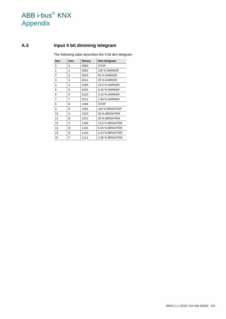
ABB i-bus KNX Appendix
RM/S 2.1 | 2CDC 514 046 D0203 321
A.5 Input 4 bit dimming telegram
The following table describes the 4 bit dim telegram:
Dec. Hex. Binary Dim telegram 0 0 0000 STOP
1 1 0001 100 % DARKER
2 2 0010 50 % DARKER
3 3 0011 25 % DARKER
4 4 0100 12.5 % DARKER
5 5 0101 6.25 % DARKER
6 6 0110 3.13 % DARKER
7 7 0111 1.56 % DARKER
8 8 1000 STOP
9 9 1001 100 % BRIGHTER
10 A 1010 50 % BRIGHTER
11 B 1011 25 % BRIGHTER
12 C 1100 12.5 % BRIGHTER
13 D 1101 6.25 % BRIGHTER
14 E 1110 3.13 % BRIGHTER
15 F 1111 1.56 % BRIGHTER
ABB i-bus KNX Appendix
322 2CDC 514 046 D0203 | RM/S 2.1
A.6 Ordering information
Short description Description Order code bbn 40 16779 EAN
Price group
Weight 1 pcs [kg]
Pack unit [Pcs]
RM/S 2.1 Room Master Premium, MDRC 2CDG 110 095 R0011 665 67 4 P2 0.7 1

ABB i-bus KNX Appendix
RM/S 2.1 | 2CDC 514 046 D0203 323
A.7 Notizen

ABB i-bus KNX Appendix
324 2CDC 514 046 D0203 | RM/S 2.1
Notizen

ABB STOTZ-KONTAKT GmbH Eppelheimer Straße 82 69123 Heidelberg, Germany Telefon: +49 (0)6221 701 607 (Marketing) +49 (0)6221 701 434 (KNX Helpline) Telefax: +49 (0)6221 701 724 E-Mail: [email protected] [email protected] Further information and local contacts: www.abb.com/knx
Note: We reserve the right to make technical changes to the products as well as amendments to the content of this document at any time without advance no-tice. The agreed properties are definitive for any orders placed. ABB AG shall not be liable for any conse-quences arising from errors or incomplete infor-mation in this document. We reserve the rights to this document and all the items and illustrations contained therein. Reproduction, transfer to third parties or processing of the content – including sections thereof – is not permitted without prior expressed written permis-sion from ABB AG. Copyright© 2012 ABB All rights reserved
P
ublic
atio
n N
umbe
r 2C
DC
514
046
D02
03 (0
1.12
)
Contact