
Drilling Fluids & Proppant Carrier Fluids Wressle Wellsite ...
Copyright 2014, AADE This paper was prepared for presentation at the 2014 AADE Fluids Technical Conference and Exhibition held at the Hilton Houston North Hotel, Houston, Texas, April 15-16, 2014. This conference was sponsored by the American Association of Drilling Engineers. The information presented in this paper does not reflect any position, claim or endorsement made or implied by the American Association of Drilling Engineers, their officers or members. Questions concerning the content of this paper should be directed to the individual(s) listed as author(s) of this work.
Abstract
Hydraulic fracturing treatments in unconventional reservoirs continue to play an imperative role in hydrocarbon production. High clay contents of shale formations often present problems that can impede the propped fracture’s conductivity, and thus well performance. These problems include sloughing of fracture faces, proppant embedment, or fines migration. This paper presents the results of a laboratory study and field applications of a new treatment fluid to help overcome these issues and maintain longevity of the well.
The treatment fluid is designed to be injected as part of the pad fluid during the fracturing or frac-packing treatment so that an ultrathin coating is formed on the fracture faces as soon as they are generated. The primary function of this treatment fluid is to stabilize formation particulates, anchoring them in place during fracture closure, proppant embedment, and high initial well flow rates. This same treatment fluid additive can also be used to coat the proppant grains during the injection of proppant slurry stages to enhance and maintain fracture conductivity.
Results from experimental testing indicate coating with this treatment fluid forms a thin film on formation surfaces, encapsulating formation fines. This coating also enhances vertical distribution of the proppant grains, thus greatly increasing pack permeability. Proppant coating drastically enhances removal of gel residue from the proppant pack, while completely inhibiting the formation of scales, preventing the pack pore spaces from becoming clogged. Additionally, coating proppants with this new treatment fluid provides effective mitigation of formation fines and intrusion into the proppant pack from incompetent rock formations. Introduction
Initially, wells completed with gravel packs, high-rate water packs, or frac-packs often respond with high productivity. However, after this high initial production, the production flow rates drop rapidly, indicating the flow paths have been choked. Well operators often perform acid treatments on proppant packs or frac-packs to help rejuvenate well production after verification that production decline was caused by fines plugging or scale deposit. Well production is often restored, but this is usually temporary. Formation fines continue to produce and invade the proppant pack because
there is no cohesion between grains to anchor or cement the fine particulate in place. Similarly, scale precipitation reappears within the pore spaces of the formation matrix or proppant pack, or it builds up in downhole tubing because the scaling conditions still exist. Scaling problems are often an issue in offshore fields that inject seawater for pressure maintenance.
Proppant surface modification technology has evolved throughout the past few years that permits the effective coating of proppant during a fracturing treatment with a solvent-based surface modification agent (SMA). Treatment of the proppant with the SMA leaves a thin, hydrophobic film on the proppant, resulting in several significant benefits. The proppant becomes tacky, resulting in the ability to trap fines and prevent their migration into and through the pack.1-3
This SMA is a polymeric material that is not soluble in water or typical reservoir fluids. It is soluble in a few highly oxygenated solvents, and these solvents are highly water soluble. The most effective proppant coating process involves adding the SMA material directly to dry proppant grains as they are being conveyed to the fracturing fluid by means of sand screws. The auger action of sand screw results in a uniform coating of the SMA on the proppant. Then, as the coated proppant is transferred into the water-based fracturing fluid, the SMA-oxygenated solvent partitions into the water phase, leaving behind a very tacky, insoluble coating on the proppant, which provides a host of benefits. However, an operational disadvantage of using a SMA is that the fracturing equipment becomes coated with the SMA, resulting in tacky equipment and requiring special cleanup procedures.
A laboratory study4 and a limited number of successful remedial treatments using diluted SMA proved that fines-damaged proppant packs can be remediated using surface modification technology. However, these remedial treatments required applying this SMA at ultralow concentrations in flammable solvents, which entailed unfavorable health and safety risks. To overcome these limitations and risks, an aqueous-based SMA system (ASMA) was successfully developed using the same well-proven SMA polymeric material. Currently, it is possible to effectively perform remedial treatments by placing highly diluted ASMA into water-based treating fluids.
Various studies were performed to evaluate the treatment
AADE-14-FTCE-38
Coating of Fracture Faces and Proppant to Enhance and Maintain Well Productivity P.D. Nguyen, L.K. Vo, and J.W. Ogle, Halliburton
2 P.D. Nguyen, L.K. Vo, and J.W. Ogle AADE-14-FTCE-38
of fracture faces with ASMA by including this treatment fluid as part of the pad fluid, such that a thin film of ASMA is coated onto the fracture faces as soon as the they are being generated, to determine the effectiveness of this coating in enhancing the attachment of proppant to the treated surface. Also, mechanisms were examined to determine if coating the water-based aggregating agent on a formation particulate could significantly impact the migration behaviors of formation fines into the pore spaces of the formation or proppant pack and maintain their permeability. In addition to the aggregating property of the ASMA solution, its scale-forming mitigation potential was also examined in formation sand packs and proppant packs. The mechanism for this scale inhibition works by changing particulate surfaces from hydrophilic to hydrophobic to minimize interaction between the scale-forming water and solid substrate surface. Fines Migration
Formation sand and fines can be released during production as a result of shear failure if drawdown pressures exceed the yield strength of the rock. Gravel-pack completions were typically designed to control formation-sand production. However, as fines begin to migrate and damage the gravel matrix, efforts are often focused on removing fines from the gravel, without allowing for the need to prevent fines production at its sources. Often, an acid treatment, such as hydrofluoric (HF) acidizing, used in the workover to remove the bridging fines, can actually further weaken the formation and enhance the production of fines, worsening the problem.5
In addition to fines damage in the gravel, the sand screens used to retain the gravel can also experience a plugging problem caused by the fine particles. On the other hand, if these fine particles pass through the screen, local erosion of the screen can become an additional concern. Various cleanup methods have been implemented to remove screen plugging and increase productivity.5,6 Submersible pumps are also susceptible to damage from produced fluids that contain formation fines and sand particulates. Scale Formation
Scale formation is a buildup of inorganic minerals in the reservoir formation and production equipment. Deposition of inorganic mineral scale in oil-bearing formations, on production tubing, or on sand screens, causes equipment failure, flow restriction, and can promote corrosion, causing a decrease in well production, a reduction of injectivity in injection wells, or costly equipment replacement. Scale precipitation within the formation matrix or proppant packs is also known to cause pore spaces to become clogged or impermeable to flowing fluids. Some scales can also cause issues when the surface equipment is in contact with certain brines.
The primary scale types are carbonates and sulfates of calcium, barium, and strontium. These compounds can precipitate as a result of changes in pressure, temperature, and ionic strength of produced fluids, or when connate reservoir waters mix with injected waters during secondary recovery
operations. Mackay7 provides excellent descriptions of various scale types and the mechanisms that cause their formation during different periods of reinjecting produced water for maintaining reservoir pressure and sweeping hydrocarbons toward production wells. Franco et al.8 identify a variety of mineral scales precipitated in the sand face and production tubulars of gas-condensate wells. To help avoid costly production losses or requiring the use of post-scale treatments, it is more efficient if the deposition of scale downhole can be prevented. ASMA
The ASMA is an aqueous-based solution containing an agglomerating agent. The agglomerating agent is a resinous material that provides adhesion or agglomerating propensity between formation surfaces and proppant grains; it also does not harden or cure under reservoir conditions.
The active ingredient in the agglomerating agent is a blend of fatty acids derived from soy or pine industries, which is condensed with polyamine to form a polyamide. This polyamide is not soluble in normal well fluids or well-treating fluids, which helps provide long-lasting benefits. The macromolecule is stable and resists attack by acid and caustic agents, except under extreme conditions. Additionally, the polymer does not contain chemical entities that change fluid properties. This characteristic is a tremendous advantage because the polymer is easily applied as a treatment fluid by injecting it as part of the pad fluid at the beginning of the hydraulic fracturing treatment.
The polymer tends to spread on the mineral surface, with the polar backbone strongly adsorbing while the hydrophobic branch groups extend away from the polar mineral surface, appearing as bushy appendages. The bushy appendages tend to associate with one another. The polymer is designed so that the spacing between hydrophobic branches allows them to “just fit” together, resulting in a significantly increased surface area available for association. Although sufficient force can pull molecules apart without breaking carbon-carbon bonds, these associations can reform repeatedly on contact. Experiments and Results Treating Fracture Faces
When treatment fluids containing ASMA are applied to the fracture faces during a fracturing treatment, the ASMA forms a thin, hydrophobic film on the treated surfaces and renders grains tacky. The objective of this part of the study was to determine the effectiveness of using ASMA to enhance the vertical distribution of proppant in created fractures.
AADE-14-FTCE-38 Coating of Fracture Faces and Proppant to Enhance and Maintain Well Productivity 3
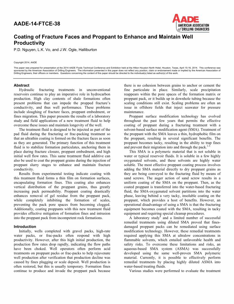
Preparation of Split Berea and Shale Cores Cores with a 1-in. diameter and 2-in. length were obtained
from outcroppings of Berea sandstone and shale formations. The dimensions and mass of the cores were recorded. The fracture plane on the core was visually determined. A Dremel®
tool was used to score and form an indentation on the top of the core. A wide-blade chisel and hammer were used to carefully split the core on the plane, along its axial length, into two halves (Fig. 1).
Fig. 1—The two surfaces of a split (a) Berea core and (b) shale core.
Permeability of Non-split Shale Cores. Before splitting the cores, the non-split cores were subjected to core flow testing with nitrogen gas to determine their matrix permeabilities. The core was installed in a Hassler sleeve. The confining pressure on the core was gradually increased to 1,200 psi, and the flowing exit backpressure was set to 200 psi. Permeability measurements were determined with three different flow rates and their corresponding differential pressures by starting from the high flow rate. Table 1 shows the permeabilities of the non-split cores for shale materials.
Table 1—Permeability of Non-Split Cores at 1,000-psi
Confinement Core Material Non-Split Permeability (md)
Berea 45 Shale 0.02
Initial Permeability of Split Berea and Shale Cores (without Treatment)
The two halves of each core were immersed in a brine fluid containing a clay stabilizer, and then they were carefully matched up, put back together, and installed in the Hassler sleeve to determine the initial permeability of the split core. The confining pressure on the core was gradually increased to 1,200 psi, and flowing backpressure was set to 200 psi. Permeability measurements (Table 2) were determined with nitrogen gas at three different flow rates and their
corresponding differential pressures by beginning from the high flow rate. Final Permeability of Split Berea and Shale Cores (with Treatment)
To determine the impact of treatment with an ASMA solution and propping agent, the split cores were disassembled after initial permeability measurements, and the fracture faces of the two halves were immersed vertically in a 5% (v/v) ASMA solution at 140°F for 10 min. After removing them from the ASMA solution, they were immediately immersed, also vertically, for 20 min in a 70/170-mesh sand slurry at 140°F, with a sand concentration of 0.5 lbm/gal. Both the ASMA solution and sand slurry were stirred with a stirring bar at 700 rev/min. The ASMA solution was prepared in an aqueous-based fluid containing an organic clay stabilizer (OCS). The sand slurry was prepared in a 3% KCl brine or slickwater.
After the immersion periods in the ASMA solution and sand slurry, the treated halves were then carefully reassembled with their faces aligned together for core flow testing with nitrogen gas under the same closure stress and backpressure applied in the initial permeability flow testing (the outside of the re-assembled cylinder was wiped clean of any sand grains). For the baseline testing, the step involving the two halves being immersed in ASMA immersion was omitted. Table 2 shows the permeability measurements of the fractured
4 P.D. Nguyen, L.K. Vo, and J.W. Ogle AADE-14-FTCE-38
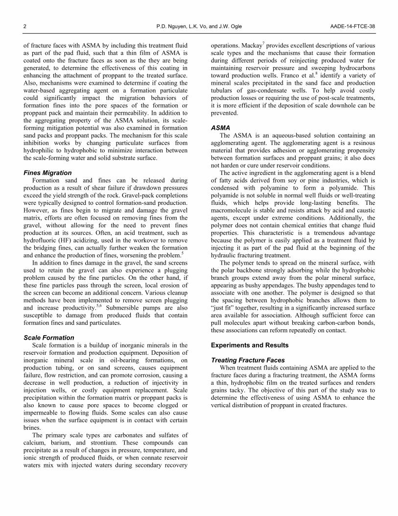
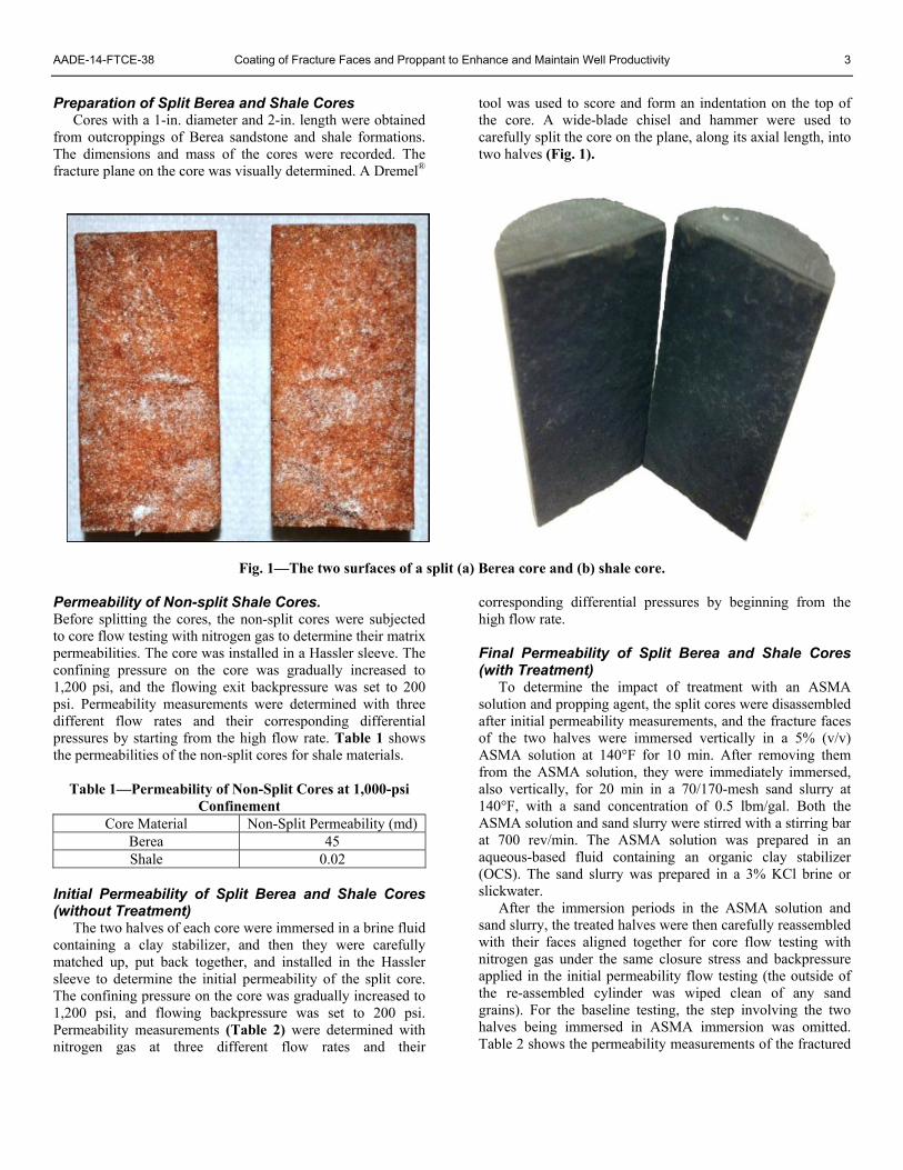
cores, before and after treatments of the ASMA solution and proppant slurry, or with and without the ASMA treatment. The micrographs from scanning electron microscopy (SEM)
analyses (Figs. 2 and 3) confirm the attachment of proppant particulates on the fracture faces of shale and Berea cores split and treated with ASMA.
Table 2—Nitrogen Gas Permeability through Split Cores under 1,000-psi Closure Stress
Core Material
Initial Perm (md)
Final Perm (md)—Fracture Faces Exposed to
70/170-mesh Sand Slurry Only
Final Perm (md)—Fracture Faces Exposed to ASMA Solution and 70/170-mesh
Sand Slurry Berea 399 — 1,503 Berea 765 — 1,479
Berea 204 — 1,798 (Exposed to 40/70-mesh sand slurry in
slickwater) Shale 14 — 1,708 (Sand slurry in slickwater) Shale 2 17 — Shale 5 25 (Sand slurry in slickwater) — Shale 14 — 304
Fig. 2—Fracture face of shale core (a) before immersion and (b) after the core flow test for cores immersed in the ASMA solution and sand slurry. A stress load of 1,200 psi was applied on the split core at the right during the flow test.
Fig. 3—Fracture face of Berea core (a) before and (b) after the core flow test for cores immersed in the ASMA solution and sand slurry. A stress load of 3,000 psi was applied on the split core on the right during the flow test.
SMA Coating on Proppant to Prevent Embedment and Invasion of Formation Sand into Proppant Pack
This part of the study was performed to examine how the coating of SMA material on proppant could significantly impact the migration behaviors of formation particulates into the proppant pack and maintain its permeability.
Brazos River sand (BRS) with a particle size smaller than 200-mesh was used to simulate unconsolidated formation faces. Core wafers were prepared with this material before the cores were installed in the API (linear conductivity) cell, sandwiching the proppant between the BSR core wafers.
The proppant and its coating treatments were evaluated at a proppant loading of 5.0 lbm/ft² at 250°F and 325°F. This testing used simulated flow-rate cycles between 25 and 12.5 MMscf/D, and stress cycles of 4,000 and 2,000 psi for conductivity and fines migration study. The proppant and coating treatments included the following:
• Baseline—Uncoated, 20/40-mesh, intermediate-strength ceramic.
• SMA-coated 20/40-mesh, intermediate-strength ceramic.
Testing Objectives
• Evaluate conductivity of a 5-lbm/ft2 ceramic proppant pack (with 20/40-mesh size) placed between the unconsolidated BRS wafers, following cyclic closure at high gas flow rates and high temperatures (control or baseline).
• Compare the effects of embedment and fines migration into the proppant pack after the proppant was coated with 2% SMA (v/w).
Testing Procedures
The effects of closure stresses and flow rates on the SMA-treated proppant were evaluated with a modified API-linear conductivity cell. The following procedure was used for measuring conductivity and the post-treatment analysis.
1. Obtain a Berea sandstone backing core with a 200- to 500-md permeability range.
2. Form simulated formation sand wafer using a BRS source with a size less than 200-mesh by placing wet sand in the core mold and freeze it in dry ice (avoid dehydration).
3. Assemble a conductivity test cell containing a core-proppant sandwich of Berea core, frozen formation sand wafer, 5-lbm/ft2 proppant (with or without additive coating). Next, fill porosity with water and then place another frozen formation sand wafer on top, and then top with a Berea sandstone backing core (Fig. 4 shows an assembly such as this after removal from the test cell following one of the test cycles).
4. Place the fully assembled conductivity test cell in a press, assemble the appropriate plumbing, and
increase closure to 1,000 psi at a rate of 100 psi/min, while opening the fluid proppant entrance and exit lines of the proppant pack. After the stress has reached 1,000 psi, close the entrance and exit valves.
5. At the cell exit collect all fines from the effluent for all flow test periods, and record the mass.
6. Begin a heat ramp and closure stress ramp from room temperature and 1,000 psi. Adjust to 4,000 psi and 250°F during a 2-hr incremental ramp of closure and temperature. When the cell temperature reaches 120°F, open the core leakoff lines for excess fluid leakoff, while maintaining a backpressure of 100 psi.
7. After obtaining 4,000 psi and 250°F, shut in for 12 hr at temperature and closure stress.
8. After completing the 12 hr shut-in period, begin flowing through the proppant pack and obtaining conductivity with de-oxygenated 2% KCl water at rates between 2 and 25 mL/min (or as required to achieve valid data based on the specific proppant pack permeability).
9. Obtain conductivity measurements with gas through the proppant pack using selected incremental rates (up-ramp and down-ramp rate, approximately 16 total rates).
10. Flow gas through both cores into (and exiting) the proppant pack for 4 hr at an equivalent rate of 25 MMscf/D (based on a 50-ft fracture height) at initially at 4,000 psi stress (normal to the fracture flow direction, through the formation core).
11. Reduce the closure stress to 2,000 psi and the gas equivalent flow rate to 12.5 MMscf/D; continue to flow gas through the core and out the fracture for 4 hr.
12. Increase closure stress back to 4,000 psi and the gas equivalent flow rate to 25 MMscf/D through the core and out the pack for 4 hr.
13. Obtain the second gas sweep (same as previous steps).
14. Repeat the closure stress and rate cycle (steps 11-13) two additional times, obtaining a gas conductivity analysis sweep at each 4,000-psi stress for comparison of flow capacity damage caused by fines migration.
15. Obtain conductivity measurements with water flow after the fourth gas flow analysis through the proppant pack.
16. Increase temperature to 325°F, and repeat Steps 8 through 15.
17. Cool, remove the cell from the press, and freeze before the removal of the core proppant sandwich from the test cell (see Fig. 4).
18. Keep frozen until post-test photographical documentation with digital camera and binocular microscope can be finalized.
6 P.D. Nguyen, L.K. Vo, and J.W. Ogle AADE-14-FTCE-38
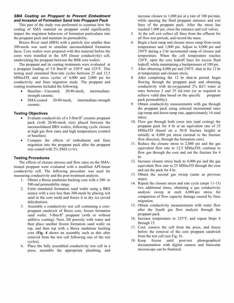
Fig. 4—A post-test proppant pack sandwiched between unconsolidated BRS (< 200 mesh). Berea wafers (they are coated by red silastic) supported both the top and bottom of the unconsolidated sand. The vertical arrows show the flow directions of the gas core flow from both directions (formation production direction: up and down). The left-to-right arrow shows the proppant pack flow direction during conductivity evaluation to water and gas.
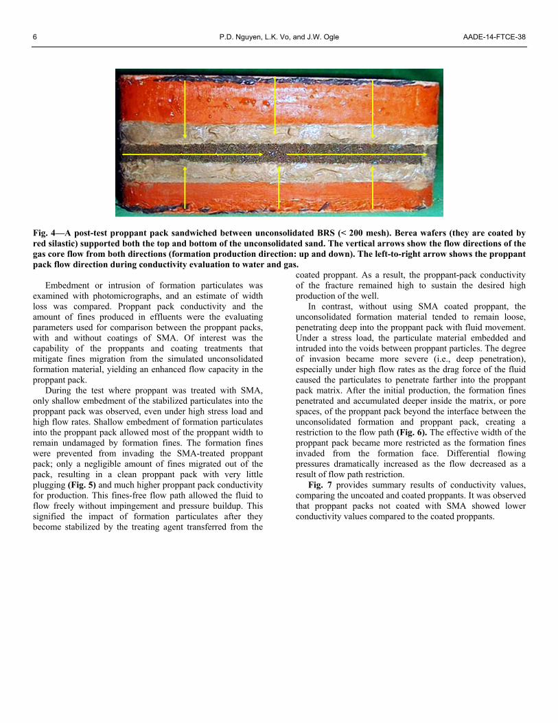
Embedment or intrusion of formation particulates was examined with photomicrographs, and an estimate of width loss was compared. Proppant pack conductivity and the amount of fines produced in effluents were the evaluating parameters used for comparison between the proppant packs, with and without coatings of SMA. Of interest was the capability of the proppants and coating treatments that mitigate fines migration from the simulated unconsolidated formation material, yielding an enhanced flow capacity in the proppant pack.
During the test where proppant was treated with SMA, only shallow embedment of the stabilized particulates into the proppant pack was observed, even under high stress load and high flow rates. Shallow embedment of formation particulates into the proppant pack allowed most of the proppant width to remain undamaged by formation fines. The formation fines were prevented from invading the SMA-treated proppant pack; only a negligible amount of fines migrated out of the pack, resulting in a clean proppant pack with very little plugging (Fig. 5) and much higher proppant pack conductivity for production. This fines-free flow path allowed the fluid to flow freely without impingement and pressure buildup. This signified the impact of formation particulates after they become stabilized by the treating agent transferred from the
coated proppant. As a result, the proppant-pack conductivity of the fracture remained high to sustain the desired high production of the well.
In contrast, without using SMA coated proppant, the unconsolidated formation material tended to remain loose, penetrating deep into the proppant pack with fluid movement. Under a stress load, the particulate material embedded and intruded into the voids between proppant particles. The degree of invasion became more severe (i.e., deep penetration), especially under high flow rates as the drag force of the fluid caused the particulates to penetrate farther into the proppant pack matrix. After the initial production, the formation fines penetrated and accumulated deeper inside the matrix, or pore spaces, of the proppant pack beyond the interface between the unconsolidated formation and proppant pack, creating a restriction to the flow path (Fig. 6). The effective width of the proppant pack became more restricted as the formation fines invaded from the formation face. Differential flowing pressures dramatically increased as the flow decreased as a result of flow path restriction.
Fig. 7 provides summary results of conductivity values, comparing the uncoated and coated proppants. It was observed that proppant packs not coated with SMA showed lower conductivity values compared to the coated proppants.
AADE-14-FTCE-38 Coating of Fracture Faces and Proppant to Enhance and Maintain Well Productivity 7
(a) (b)
Fig. 5—(a) Only minimum embedment or intrusion of formation fines into the SMA-coated proppant pack was found, retaining all proppant width; (b) a close-up view of the SMA-coated proppant pack indicating that formation fines stopped at the interface without migrating deep inside the pack. The white spots in the proppant pack are water beads, not fines.
(a) (b)
Fig. 6—(a) Embedment of BRS fines into the uncoated proppant pack at the interface between the proppant and unconsolidated formation; (b) it was determined that more formation fines had migrated deep inside the proppant matrix.
Fig. 7—Treating of proppant with SMA materials dramatically increased the conductivity of proppant packs compared to that of the untreated proppant.
8 P.D. Nguyen, L.K. Vo, and J.W. Ogle AADE-14-FTCE-38
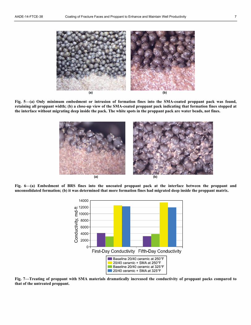
Maximizes Breaker Efficiency and Enhances Fluid Recovery
By coating the proppant with the SMA, substantially encapsulating each grain, the SMA helps prevent fracturing gel adsorption onto the proppant surface. This coating substantially increases the effectiveness of gel breakers to reduce gel viscosity thus promoting more effective fracture cleanup (Fig. 8). Enhanced fluid-recovery tests demonstrate that gelled fluids inside pores of SMA-treated proppant cleans up faster and more completely than with untreated proppant.2 This experiment supports the theory that a SMA-coated proppant can prevent aqueous-based polymer fluids from adsorbing onto the proppant surface, thereby allowing gel breakers to break the fluid completely. Testing indicates that SMA treated packs are more permeable to both oil and water than untreated packs (Fig. 9). When given the same amount of time for cleanup as the untreated pack, the treated pack allows a much greater volume of cleanup fluid to pass, suggesting that faster and greater production levels can be obtained from the well.
Fig. 8 illustrates the effect of SMA coating on reducing polymer damage to a pack. Fig. 9 illustrates the efficiency of gelled fluid recovery by comparing SMA-coated sand to uncoated sand.
Fig. 8—The effect of SMA coating on reducing polymer damage to a pack was determined using API conductivity measurements with 20/40-mesh sand at 150°F.
Fig. 9—Efficiency of fluid recovery was demonstrated by comparing SMA-coated sand to uncoated sand. Two columns were filled with proppant-laden fracturing fluid and shut in for 24 hr to allow the enzyme breaker to degrade the guar-gum polymer.
Remedial Treatment—Injecting through Propped Fracture for Treating Proppant Pack and Formations Adjacent Fracture Faces
ASMA is aqueous-based and can be diluted in brine for deep injection into existing proppant packs. This enables its use for remedial treatments to repair fines-damaged frac-packs, where frequent acid treatments are required to maintain acceptable production. New emulsion technology allows the SMA release from the ASMA to be delayed. The delayed delivery of the SMA permits direct injection into proppant packs and the formation matrix to provide methods for remedial fines treatments, resulting in longer lasting acid stimulation of frac-pack completions.
Fines Stabilization in Unconsolidated Formation with ASMA Treatment
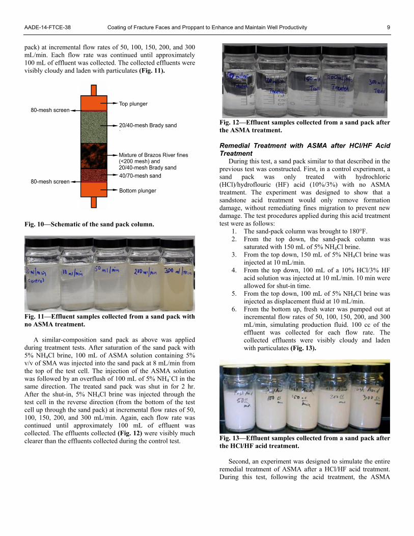
During this test series, the effect of migration/invasion of formation sand or fines into a gravel pack or proppant pack was simulated. Brady 20/40-mesh sand, or ceramic proppant with a larger mesh size of 16/30, was purposely selected to allow fines particulates to invade and migrate into the pack so the migrated materials could be measured and compared between untreated and treated sand packs. The formation sand pack was simulated by mixing in a weight ratio of one part BRS fines (<200 mesh) with two parts 20/40-mesh Brady sand.
From top to bottom, the test cell contained a top plunger, an 80-mesh screen, a layer of 20/40-mesh Brady sand (or 16/30 ceramic, although this data not included), the 33% BRS fines, a layer of 40/70-mesh sand, an 80-mesh screen, and a bottom plunger (Fig. 10). For a control test using a peristaltic pump, 100 mL of 5% NH4Cl brine was injected from the top of the test cell at 8 mL/min to saturate the sand pack. The KCl brine was then flowed through the test cell in the reverse direction (from the bottom of the test cell up through the sand
AADE-14-FTCE-38 Coating of Fracture Faces and Proppant to Enhance and Maintain Well Productivity 9
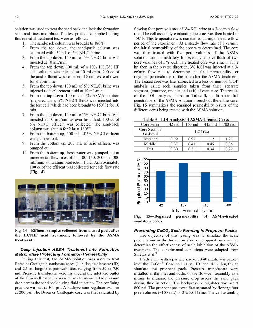
pack) at incremental flow rates of 50, 100, 150, 200, and 300 mL/min. Each flow rate was continued until approximately 100 mL of effluent was collected. The collected effluents were visibly cloudy and laden with particulates (Fig. 11).
Fig. 10—Schematic of the sand pack column.
Fig. 11—Effluent samples collected from a sand pack with no ASMA treatment.
A similar-composition sand pack as above was applied
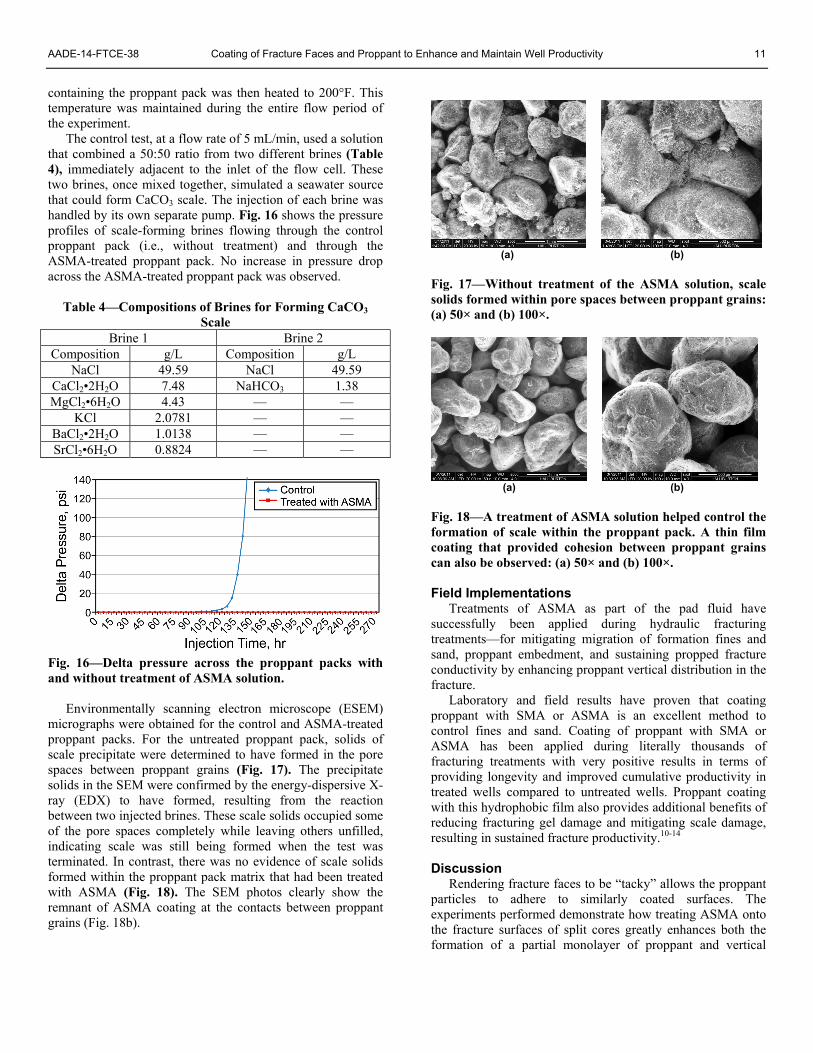
during treatment tests. After saturation of the sand pack with 5% NH4Cl brine, 100 mL of ASMA solution containing 5% v/v of SMA was injected into the sand pack at 8 mL/min from the top of the test cell. The injection of the ASMA solution was followed by an overflush of 100 mL of 5% NH4`Cl in the same direction. The treated sand pack was shut in for 2 hr. After the shut-in, 5% NH4Cl brine was injected through the test cell in the reverse direction (from the bottom of the test cell up through the sand pack) at incremental flow rates of 50, 100, 150, 200, and 300 mL/min. Again, each flow rate was continued until approximately 100 mL of effluent was collected. The effluents collected (Fig. 12) were visibly much clearer than the effluents collected during the control test.
Fig. 12—Effluent samples collected from a sand pack after the ASMA treatment.
Remedial Treatment with ASMA after HCl/HF Acid Treatment
During this test, a sand pack similar to that described in the previous test was constructed. First, in a control experiment, a sand pack was only treated with hydrochloric (HCl)/hydroflouric (HF) acid (10%/3%) with no ASMA treatment. The experiment was designed to show that a sandstone acid treatment would only remove formation damage, without remediating fines migration to prevent new damage. The test procedures applied during this acid treatment test were as follows:
1. The sand-pack column was brought to 180°F. 2. From the top down, the sand-pack column was
saturated with 150 mL of 5% NH4Cl brine. 3. From the top down, 150 mL of 5% NH4Cl brine was
injected at 10 mL/min. 4. From the top down, 100 mL of a 10% HCl/3% HF
acid solution was injected at 10 mL/min. 10 min were allowed for shut-in time.
5. From the top down, 100 mL of 5% NH4Cl brine was injected as displacement fluid at 10 mL/min.
6. From the bottom up, fresh water was pumped out at incremental flow rates of 50, 100, 150, 200, and 300 mL/min, simulating production fluid. 100 cc of the effluent was collected for each flow rate. The collected effluents were visibly cloudy and laden with particulates (Fig. 13).
Fig. 13—Effluent samples collected from a sand pack after the HCl/HF acid treatment.
Second, an experiment was designed to simulate the entire remedial treatment of ASMA after a HCl/HF acid treatment. During this test, following the acid treatment, the ASMA
10 P.D. Nguyen, L.K. Vo, and J.W. Ogle AADE-14-FTCE-38
solution was used to treat the sand pack and lock the formation sand and fines into place. The test procedures applied during this remedial treatment test were as follows:
1. The sand-pack column was brought to 180°F. 2. From the top down, the sand-pack column was
saturated with 150 mL of 5% NH4Cl brine. 3. From the top down, 150 mL of 5% NH4Cl brine was
injected at 10 mL/min. 4. From the top down, 100 mL of a 10% HCl/3% HF
acid solution was injected at 10 mL/min. 200 cc of the acid effluent was collected. 10 min were allowed for shut-in time.
5. From the top down, 100 mL of 5% NH4Cl brine was injected as displacement fluid at 10 mL/min.
6. From the top down, 100 mL of 5% ASMA solution (prepared using 5% NH4Cl fluid) was injected into the test cell (which had been brought to 150°F) for 10 min.
7. From the top down, 100 mL of 5% NH4Cl brine was injected at 10 mL/min as overflush fluid. 100 cc of 5% NH4Cl effluent was collected. The sand-pack column was shut in for 2 hr at 180°F.
8. From the bottom up, 100 mL of 5% NH4Cl effluent was pumped out.
9. From the bottom up, 200 mL of acid effluent was pumped out.
10. From the bottom up, fresh water was pumped out at incremental flow rates of 50, 100, 150, 200, and 300 mL/min, simulating production fluid. Approximately 100 cc of the effluent was collected for each flow rate (Fig. 14).
Fig. 14—Effluent samples collected from a sand pack after the HCl/HF acid treatment, followed by the ASMA treatment.
Deep Injection ASMA Treatment into Formation
Matrix while Protecting Formation Permeability During this test, the ASMA solution was used to treat
Berea or Castlegate sandstone cores (1-in. inside diameter (ID) and 2.5-in. length) at permeabilities ranging from 50 to 750 md. Pressure transducers were installed at the inlet and outlet of the flow-cell assembly as a means to measure the pressure drop across the sand pack during fluid injection. The confining pressure was set at 500 psi. A backpressure regulator was set at 200 psi. The Berea or Castlegate core was first saturated by
flowing four pore volumes of 3% KCl brine at a 3-cc/min flow rate. The cell assembly containing the core was then heated to 180°F. This temperature was maintained during the entire flow period of the experiment. At a steady flow rate of 3 cc/min, the initial permeability of the core was determined. The core was then treated with five pore volumes of the ASMA solution, and immediately followed by an overflush of two pore volumes of 3% KCl. The treated core was shut in for 2 hr; then in the reverse direction, 3% KCl was injected at a 3-cc/min flow rate to determine the final permeability, or regained permeability, of the core after the ASMA treatment. The treated core was later subjected to a loss on ignition (LOI) analysis using rock samples taken from three separate segments (entrance, middle, and exit) of each core. The results of the LOI analyses, listed in Table 3, confirm the full penetration of the ASMA solution throughout the entire core. Fig. 15 summarizes the regained permeability results of the different cores being treated with the ASMA solution.
Table 3—LOI Analysis of ASMA-Treated Cores Core Perm 42 md 155 md 415 md 700 md
Core Section Analyzed
LOI (%)
Entrance 0.79 0.92 1.12 1.23 Middle 0.37 0.41 0.45 0.36
Exit 0.30 0.36 0.34 0.29
Fig. 15—Regained permeability of ASMA-treated sandstone cores. Preventing CaCO3 Scale Forming in Proppant Packs
The objective of this testing was to simulate the scale precipitation in the formation sand or proppant pack and to determine the effectiveness of scale inhibition of the ASMA treatment. The experimental conditions were adapted from Shields et al.9
Brady sand, with a particle size of 20/40 mesh, was packed into the Teflon® flow cell (1-in. ID and 4-in. length) to simulate the proppant pack. Pressure transducers were installed at the inlet and outlet of the flow-cell assembly as a means to measure the pressure drop across the sand pack during fluid injection. The backpressure regulator was set at 800 psi. The proppant pack was first saturated by flowing four pore volumes (~100 mL) of 3% KCl brine. The cell assembly
AADE-14-FTCE-38 Coating of Fracture Faces and Proppant to Enhance and Maintain Well Productivity 11
containing the proppant pack was then heated to 200°F. This temperature was maintained during the entire flow period of the experiment.
The control test, at a flow rate of 5 mL/min, used a solution that combined a 50:50 ratio from two different brines (Table 4), immediately adjacent to the inlet of the flow cell. These two brines, once mixed together, simulated a seawater source that could form CaCO3 scale. The injection of each brine was handled by its own separate pump. Fig. 16 shows the pressure profiles of scale-forming brines flowing through the control proppant pack (i.e., without treatment) and through the ASMA-treated proppant pack. No increase in pressure drop across the ASMA-treated proppant pack was observed.
Table 4—Compositions of Brines for Forming CaCO3 Scale
Brine 1 Brine 2 Composition g/L Composition g/L
NaCl 49.59 NaCl 49.59 CaCl2•2H2O 7.48 NaHCO3 1.38 MgCl2•6H2O 4.43 — —
KCl 2.0781 — — BaCl2•2H2O 1.0138 — — SrCl2•6H2O 0.8824 — —
Fig. 16—Delta pressure across the proppant packs with and without treatment of ASMA solution.
Environmentally scanning electron microscope (ESEM) micrographs were obtained for the control and ASMA-treated proppant packs. For the untreated proppant pack, solids of scale precipitate were determined to have formed in the pore spaces between proppant grains (Fig. 17). The precipitate solids in the SEM were confirmed by the energy-dispersive X-ray (EDX) to have formed, resulting from the reaction between two injected brines. These scale solids occupied some of the pore spaces completely while leaving others unfilled, indicating scale was still being formed when the test was terminated. In contrast, there was no evidence of scale solids formed within the proppant pack matrix that had been treated with ASMA (Fig. 18). The SEM photos clearly show the remnant of ASMA coating at the contacts between proppant grains (Fig. 18b).
(a) (b)
Fig. 17—Without treatment of the ASMA solution, scale solids formed within pore spaces between proppant grains: (a) 50× and (b) 100×.
(a) (b)
Fig. 18—A treatment of ASMA solution helped control the formation of scale within the proppant pack. A thin film coating that provided cohesion between proppant grains can also be observed: (a) 50× and (b) 100×. Field Implementations
Treatments of ASMA as part of the pad fluid have successfully been applied during hydraulic fracturing treatments—for mitigating migration of formation fines and sand, proppant embedment, and sustaining propped fracture conductivity by enhancing proppant vertical distribution in the fracture.
Laboratory and field results have proven that coating proppant with SMA or ASMA is an excellent method to control fines and sand. Coating of proppant with SMA or ASMA has been applied during literally thousands of fracturing treatments with very positive results in terms of providing longevity and improved cumulative productivity in treated wells compared to untreated wells. Proppant coating with this hydrophobic film also provides additional benefits of reducing fracturing gel damage and mitigating scale damage, resulting in sustained fracture productivity.10-14
Discussion
Rendering fracture faces to be “tacky” allows the proppant particles to adhere to similarly coated surfaces. The experiments performed demonstrate how treating ASMA onto the fracture surfaces of split cores greatly enhances both the formation of a partial monolayer of proppant and vertical
12 P.D. Nguyen, L.K. Vo, and J.W. Ogle AADE-14-FTCE-38
distribution of the particles, thus greatly improving the conductivity of the propped fracture. Instead of forming a densely packed monolayer on the split surface, proppant grains were found adhered to the treated face individually or in clusters of several grains, and they were distributed randomly throughout the treated surfaces.
During an actual hydraulic fracturing treatment, ASMA is applied as part of the pad fluid stage to treat the fracture faces before placement of the proppant into the fractures. The ASMA treatment forms a thin film that becomes tacky and hydrophobic on both the fracture face and formation particulates. This coating causes the proppant to adhere to the created fracture faces to mitigate proppant settling, resulting in improved vertical distribution of proppant within the fracture.
Without treating the faces of split cores using ASMA, the proppant grains tended to be easily detached and fell off the core surface, resulting in very few grains remaining on the surface. The permeability measurements of the split cores that were only treated with proppant slurry were slightly higher than those of unpropped, split cores (Table 2). However, the split cores treated using both the ASMA solution and proppant slurry had permeability increases of multiple folds compared to those of unpropped, split cores and those treated with only proppant (Table 2).
Coating of proppant with SMA or ASMA provides a delivery mechanism to treat the formation face in the fracture. The transfer of the coated material from the proppant to the formation transformed the loosely consolidated particulates into a more cohesive, bounded porous medium. This cohesion entrapped the particulates, stabilizing them in place without allowing individual particulates to migrate into the proppant pack. Embedment depth of formation particulates into the fracture proppant pack is shown to significantly impact the proppant-pack permeability/conductivity by decreasing the effective width of the proppant pack.
The coating of a tacky film of SMA or ASMA, although not sufficient to consolidate the formation particulates, was shown to provide sufficient adhesion between the particulates, attaching the fines particulate onto larger particles and anchoring them in place. The established cohesion allowed the particulates to withstand drag forces from high flow rates.
The injection of the diluted ASMA solution as a remedial treatment was determined to effectively control the migration of fines after the core had been subjected to an HF acid treatment. This stabilization of the formation after the acid treatment should help alleviate problems of migrating formation fines and help prolong the production of the well. Without treatment of the ASMA solution, formation fines were shown to migrate readily into the highly permeable proppant pack to simulate a damaged proppant pack, such as a frac-pack completion. However, once the remedial treatment using ASMA was performed on this fines-laden proppant and loose-sand pack, the production of fines was drastically mitigated, even at much higher simulated production flow rates, and with or without an acid pretreatment.
The coating of ASMA forms a hydrophobic film on the particulate surface. This thin coating minimizes the exposure
of the particulate surface to interaction with scale-forming brine. Without the coating of ASMA, the increases of differential pressures across the sand packs indicate that scale deposits readily anchor onto the uncoated substrates, thereby reducing the pore spaces of the sand matrix and choking its flow capacity (Figs. 17 and 18). Conclusions Based on the results of this study, the following conclusions were reached:
• A water-based aggregating agent has been formulated that permits injection into formations as part of the pad fluid of the hydraulic fracturing treatment, or into the formation sand or proppant packs as primary or remedial treatments.
• The ASMA treatment promotes the adhesion of proppant onto the treated fracture faces so that vertical distribution of proppant is enhanced, thus increasing the effective permeability of the propped fracture.
• ASMA provides an effective means for controlling the migration of formation fines particulate into the gravel-pack annulus or proppant pack in the propped fractures.
• SMA materials coated onto the proppant help minimize the loss of conductivity associated with formation mechanical properties by stabilizing the formation surface at the interface.
• After an acid treatment on a sandstone formation, ASMA-treated formations can withstand high flow rates with stabilized fines.
• The treatments of ASMA on sand packs indicate that the hydrophobic coating of an aggregating agent helps mitigate the deposition of CaCO3 scale in the pore space of sand packs.
Acknowledgments
The authors thank Halliburton for the permission to publish this paper. References 1. Nguyen, P., Weaver, J., Dewprashad, B., Parker, M., and
Terracina, J. 1998. Enhancing Fracture Conductivity Through Surface Modification of Proppant. Paper SPE 39428 presented at the SPE Formation Damage Control Conference, Lafayette, Louisiana, USA, 18–19 February. http://dx.doi.org/10.2118/39428-MS.
2. Nguyen, P.D., Dewprashad, B.T., and Weaver, J.D. 2000. New Approach for Enhancing Fracture Conductivity. SPE Prod. & Facilities 15 (2): 83–89. SPE-63010-PA. http://dx.doi.org/10.2118/63010-PA.
3. Weaver, J., Baker, J., Woolverton, S., and Parker, M. 1999. Application of Surface-Modification Agent in Wells with High Flow Rates. Paper SPE 53923 presented at the Latin American and Caribbean Petroleum Engineering Conference, Caracas, Venezuela, 21–23 April. http://dx.doi.org/10.2118/53923-MS.
4. Nguyen, P.D., Weaver, J.D., Rickman, R.D., Dusterhoft, R., and Parker, M.A. 2005. Controlling Formation Fines at Their
AADE-14-FTCE-38 Coating of Fracture Faces and Proppant to Enhance and Maintain Well Productivity 13
Sources to Maintain Well Productivity., Paper SPE 97659 presented at the SPE International Improved Oil Recovery Conference in Asia Pacific, Kuala Lumpur, Malaysia, 5–6 December. http://dx.doi.org/10.2118/97659-MS.
5. Stanley, F.O., Troncoso, J.C., Martin, A.N., and Ali Jamil, O. 2000. Matrix Acidizing Horizontal Gravel-Packed Wells for Fines Damage Removal. Paper SPE 65519 presented at the SPE/CIM International Conference on Horizontal Well Technology, Calgary, Alberta, Canada, 6–8 November. http://dx.doi.org/10.2118/65519-MS.
6. Asadi, M. and Penny, G.S. 2000. Sand Control Screen Plugging and Cleanup. Paper SPE 64413 presented at the Asia Pacific Oil and Gas Conference and Exhibition, Brisbane, Australia, 16–18 October. http://dx.doi.org/10.2118/64413-MS.
7. Mackay, E.J. 2010. Comparison of Scale Control Challenges between Production and PWRI Wells. Paper SPE 129181 presented at the International Symposium on Formation Damage Control, Lafayette, Louisiana, USA, 10–12 February. http://dx.doi.org/10.2118/129181-MS.
8. Franco, C.A., Solares, J.R., Al-Marri, H.M., et al. 2010. Analysis of Deposition Mechanism of Mineral Scales Precipitating in the Sandface and Production Strings of Gas-Condensate Wells. SPE Prod. & Oper. 25 (2). 161–171. SPE-130410-PA. http://dx.doi.org/10.2118/120410-PA.
9. Shields, R., Bourne, H., Vazquez, H, et al. 2010. Dynamic Scaling Evaluation in Gravel Packs Using Low-Sulphate Seawater. Paper SPE 128002 presented at the SPE International Symposium and Exhibition on Formation Damage Control, Lafayette, Louisiana, USA 10–12 February. http://dx.doi.org/10.2118/128002-MS.
10. Ali, S., Vitthal, S., and Weaver, J. 2000. Improvements in High-Rate Water Packing with Surface-Modification Agent. Paper SPE 58755 presented at the SPE International Symposium on Formation Damage Control, Lafayette, Louisiana, USA, 23–24 February. http://dx.doi.org/10.2118/58755-MS.
11. Lehman, L.V., Shelley, B., Crumrine, T., et al. 2003. Conductivity Maintenance: Long-Term Results from the Use of Conductivity Enhancement Material. Paper SPE 82241 presented at the SPE European Formation Damage Conference, The Hague, The Netherlands, 13–14 May. http://dx.doi.org/10.2118/82241-MS.
12. Weaver, J.D., Nguyen, P.D., Parker, M.A., and van Batenburg D. 2005. Sustaining Fracture Conductivity. Paper SPE 94666 presented at the European Formation Damage Conference, Scheveningen, The Netherlands, 25–27 May. http://dx.doi.org/10.2118/94666-MS.
13. Weaver, J., Rickman, R. and Luo, H. 2008. Fracture-Conductivity Loss Due to Geochemical Interactions Between Manmade Proppants and Formations. Paper SPE 118174 presented at the Eastern Regional/AAPG Eastern Section Joint Meeting, Pittsburgh, Pennsylvania, USA, 11–15 October. http://dx.doi.org/10.2118/118174-MS.
14. Weaver, J. and Nguyen, P.D. 2010. Hydrophobic Filming Reduces Frac Gel and Mineral Scale Damage. Paper SPE 138314 presented at the SPE Eastern Regional Meeting, Morgantown, West Virginia, USA, 13–15 October. http://dx.doi.org/10.2118/138314-MS.


![[XLS] Shale/PA-Fracking.xls · Web viewGW-3LDF, Unknown product from PDEP Diatomaceous earth, calcined 91053-39-3 Unknown product from PDEP, Bio-Clear 200 Fracturing, proppant Alpha](https://static.fdocuments.in/doc/165x107/5afd31377f8b9a444f8d19fa/xls-shalepa-frackingxlsweb-viewgw-3ldf-unknown-product-from-pdep-diatomaceous.jpg)


