A50A OWNERS MANUAL - Auto Craneautocrane.us/wp-content/uploads/A50A-999965-090203.pdf · Death or...
140
A50A OWNERS MANUAL Manual No. 999965 Rev. 9/2/2003 Serial No. __________________ Mailing Address: P.O. Box 580697 Tulsa, OK 74158-0697 Physical Address: Phone (918) 836-0463 4707 N. Mingo Rd. Fax (918) 834-5979 Tulsa, OK 74117-5904 http://www.autocrane.com
-
Upload
truongkien -
Category
Documents
-
view
214 -
download
1
Transcript of A50A OWNERS MANUAL - Auto Craneautocrane.us/wp-content/uploads/A50A-999965-090203.pdf · Death or...

A50A OWNERS MANUAL
Manual No. 999965 Rev. 9/2/2003
Serial No. __________________ Mailing Address: P.O. Box 580697 Tulsa, OK 74158-0697 Physical Address: Phone (918) 836-0463 4707 N. Mingo Rd. Fax (918) 834-5979 Tulsa, OK 74117-5904 http://www.autocrane.com


To: Fax:From: Date:Re: Pages:
Name: Phone:Address:City: State: Zip:Contact:
Name:Address:City: State: Zip:Contact:
VIN #
ONE REGISTRATION FORM PER UNIT (CRANE OR BODY)Registration form must be mailed or faxed within 15 days of customer installation.
Mail to:Warranty DepartmentAuto Crane Company
P.O. Box 581510Tulsa, OK 74158-0697
Date Product Delivered: Date Processed:** For Auto Crane use only
Product Information: (Required for Warranty Activation)
Model No.: Serial No.:
E-mail Address:
Distributor Information: (Required for Warranty Activation)
Product Registration
E-mail Address:
(Required for Warranty Activation)
Auto Crane Warranty Registration
(918) 834-5979Warranty Department
End User Information:
Fax Transmission
Warranty Registration Rev. 072403


A50A ARTICULATING CRANE MOUNTING AND INSTALLATION INSTRUCTIONS REVISION RECORD
i
Revision Date
Section(s) Or
Page(s) Description of Change
09/02/03 Last page New 2-year warranty policy to replace 1-year warranty policy


WARNINGS
READ THIS PAGE
Warnings 12/2002
WARNING! Federal law (49 cfr part 571) requires that the Final Stage Manufacturer of a vehicle certify that the vehicle complies with all applicable federal regulations. Any modifications performed on the vehicle prior to the final state are also considered intermediate stage manufacturing and must be certified as to compliance. The installer of this crane and body is considered on of the manufacturers of the vehicle. As such a manufacturer, the installer is responsible for compliance with all applicable federal and state regulations, and is required to certify that the vehicle is in compliance. WARNING! It is the further responsibility of the installer to comply with the OSHA Truck Crane Stability Requirements as specified by 29 CFR part 1910.180 (C) (1). WARNING! NEVER OPERATE THE CRANE NEAR ELECTRICAL POWER LINES! Death or serious injury will result from boom, line, or load contacting electric lines. Do not use crane within 10 feet (3.05m) of electric power lines carrying up to 50,000 volts. One foot additional clearance is required for every additional 30,000 volts or less. SEE DANGER DECAL (P/N 040529) in this Owner's Manual. WARNING! NEVER.........................................
♦ EXCEED load chart capacities (centerline of rotation to hoist hook). ♦ Un-reel last 5 wraps of cable from drum! ♦ Wrap cable around load! ♦ Attempt to lift or drag a load from the side! The boom can fail far below its rated capacity. ♦ Weld, modify, or use unauthorized components on any Auto Crane unit! This will void any
warranty or liability. Also failure of the crane may result. ♦ Place a chain link on the tip of the hook and try to lift a load! ♦ Use a sling bar or anything larger than the hook throat that could prevent the hook latch from
closing, thus negating the safety feature! ♦ Hold on any pendant Select Switch that will cause unsafe operating conditions! WARNING! In using a hook with latch, ALWAYS make sure that the hook throat is closed before lifting a load! Proper attention and common sense applied to the use of the hoist hook and various slings will prevent possible damage to material being hoisted and may prevent injury to personnel. WARNING! Failure to correctly plumb and wire crane can cause inadvertent operation and damage to crane and/or personnel! WARNING! Auto Crane Company remote controlled cranes are not designed or intended to be used for any applications involving the lifting or moving of personnel. WARNING! ALWAYS operate the crane in compliance with the load capacity chart. DO NOT USE the overload shutdown device to determine maximum rated loads, if the crane is equipped with this type of device.


LAST PAGEWARRANTY13 . . . . . . . . . . . . . . . . . . . . . . . . . . . . . . . . . . . . . . . . . . . . . . .
12-1.0.0LOAD CHART12 . . . . . . . . . . . . . . . . . . . . . . . . . . . . . . . . . . . . . . . . . . . . . .
11-1.0.0DECAL LAYOUT11 . . . . . . . . . . . . . . . . . . . . . . . . . . . . . . . . . . . . . . . . . . .
10-1.0.0GENERAL DIMENSIONS10 . . . . . . . . . . . . . . . . . . . . . . . . . . . . . . . . . . . .
9-1.0.0HYDRAULIC SECTION9 . . . . . . . . . . . . . . . . . . . . . . . . . . . . . . . . . . . . . .
8-1.0.0PROPORTIONAL CONTROL SYSTEM8 . . . . . . . . . . . . . . . . . . . . . . . . .
7-1.0.0MECHANICAL SECTION7 . . . . . . . . . . . . . . . . . . . . . . . . . . . . . . . . . . . .
6-1.0.0TROUBLESHOOTING6 . . . . . . . . . . . . . . . . . . . . . . . . . . . . . . . . . . . . . . .
5-1.0.0INSPECTION, TESTING, & MAINTENANCE5 . . . . . . . . . . . . . . . . . . . .
4-1.0.0OPERATION OF UNIT4 . . . . . . . . . . . . . . . . . . . . . . . . . . . . . . . . . . . . . . .
3-1.0.0MOUNTING & INSTALLATION3 . . . . . . . . . . . . . . . . . . . . . . . . . . . . . .
2-1.0.0SAFETY TIPS & PRECAUTIONS2 . . . . . . . . . . . . . . . . . . . . . . . . . . . . . .
1-1.0.0INTRODUCTION1 . . . . . . . . . . . . . . . . . . . . . . . . . . . . . . . . . . . . . . . . . . .
A-50A SERIES - OWNER'S MANUAL
TABLE OF CONTENTS
PAGE

AW-414 2/2000
CRANE EQUIPMENT REGISTRATION FORMRETAIN WITH MANUAL
INSTALLER TO FILL OUT AT TIME OF INSTALLATION
CHASSISMakeModel No.Serial No.Year
DISTRIBUTORInvoice no.
Cylinder No.Carburetor Type
MakeENGINE
Transfer Case Model No.
TRANSMISSIONMake
MakeTypeModel No.
GOVERNOR
MakeModel No.Serial No.
POWER TAKE OFF
Serial No.
Model No.Specification No.
MakeBODY
Serial No.
Model No.Serial No.
MakeHYDRAULIC PUMP
Model No.
WINCH MOTOR
Model No.Make
MakeWINCH GEAR BOX
Model No.Serial No.
MakeCRANE:
CUSTOMERDate:
SPECIAL EQUIPMENT
Serial No.Model No.Make

SAFETY DECAL SECTION
A50A decal 2/2000
To inform the operator of the hazard of proximity or contact with the crane boom during operation.
Both sides of outer and manualbooms.
PLACEMENT:
4QUANTITY:
FUNCTION:STAY CLEAR OF BOOMDECAL: 040517PART NO.:
Hoist hookPLACEMENT:
1QUANTITY:
To inform the operator ofthe hazard of proximityor contact with the craneload during operation.
FUNCTION:
STAY CLEAR OFLOAD
DECAL: 040518PART NO.:
To inform the operator ofpossible danger at scissors pointon crane.
FUNCTION:
Both sides of lift cylinderPLACEMENT:SCISSORS POINTDECAL:
2QUANTITY: 040519PART NO.:
0-1.0.0

SAFETY DECAL SECTION
A50A decal 2/2000
Both control handle platesPLACEMENT:
2QUANTITY:
To inform the operator of theneed to receive proper trainingbefore using the crane.
FUNCTION:OPERATOR TRAININGDECAL: 040580PART NO.:
0-2.0.0
To inform the operator of thehazard involved with contactingelectrical power lines with craneboom.
FUNCTION:
Both control handle platesPLACEMENT:ELECTROCUTION HAZARDDECAL:
2QUANTITY: 040529PART NO.:

SAFETY DECAL SECTION
A50A decal 2/2000
Both control handle platesPLACEMENT:
2QUANTITY:
To inform the operator of theproper procedure to follow forsafe operation of the crane.
FUNCTION:OPERATION INSTRUCTIONSDECAL: 040579PART NO.:
On outrigger pad, one per sidePLACEMENT:
2QUANTITY:
To inform the operator of dangerassociated with outriggers.
FUNCTION:STAND CLEARDECAL:
040581PART NO.:
0-3.0.0

SAFETY DECAL SECTION
A50A decal 2/20000-4.0.0
Both sides of loftinh hookPLACEMENT:
2QUANTITY:
To inform operator of the hazardof proximity of contact with thecrane load during operation.
FUNCTION:STAY CLEAR OF LOADDECAL:040630PART NO.:
Both control handle platesPLACEMENT:
1QUANTITY:
Inform operator of the required hydraulic requirements for properoperation of the crane.
FUNCTION:HYDRAULIC REQUIREMENTSDECAL:367213PART NO.:
Both control handle platesPLACEMENT:
2QUANTITY:
To inform operator of the propermethod to unstore and store thecrane.
FUNCTION:
ARTICULATING CRANESTORAGE
DECAL:367239PART NO.:

SAFETY DECAL SECTION
A50A decal 2/20000-5.0.0
Both control handle platesPLACEMENT:
2QUANTITY:
To inform operator of thehazard involved withcontacting electrical powerlines with crane boom.
FUNCTION:
ELECTROCUTIONHAZARD
DECAL:367241PART NO.:
Hydraulic reservoirPLACEMENT:
1QUANTITY:
To inform operator to checkfluid leveland check forleaks/damage.
FUNCTION:HYDRAULIC FLUIDDECAL:367244PART NO.:
Both control handle platesPLACEMENT:
2QUANTITY:
Inform operator of hazards ofriding load
FUNCTION:NEVER RIDE ON HOOKDECAL:367246PART NO.:

SAFETY DECAL SECTION
A50A decal 2/20000-6.0.0
Both sides of first and secondstage booms
PLACEMENT:
4QUANTITY:
To inform the operator of thehazard of proximity or contactwith the crane boom duringoperation.
FUNCTION:STAY CLEAR OF BOOMDECAL: 367251PART NO.:
Both sides of outer boomPLACEMENT:
2QUANTITY:
To inform operator of the hazardof two blocking the crane.
FUNCTION:
DANGER, TWO BLOCK (4000pound capacity)
DECAL: 367307PART NO.:

SAFETY DECAL SECTION
A50A decal 2/20000-7.0.0
Top of outrigger legPLACEMENT:
2QUANTITY:
To inform the operator of thedanger od prozimity withoutrigger and ground contactpoint.
FUNCTION:A MOVING OUTRIGGERDECAL:367433PART NO.:
Both ends of outrigger tubePLACEMENT:
2QUANTITY:
Inform operator that theoutriggers must be extended andpinned in place before operatingthe crane.
FUNCTION:EXTEND OUTRIGGERSDECAL:759016PART NO.:

NOTES

Auto Crane products are designed to provide manyyears of safe, trouble-free, dependable service whenproperly used and maintained.
To assist you in obtaining the best service fromyour crane and to avoid untimely crane and/or vehiclefailure, this manual provides the following operatingand service instructions. It is specificallyrecommended that all operating and service personnelconsider this manual as mandatory material for readingand study before operating or servicing Auto craneproducts. It is highly recommended that crane owners,equipment managers and supervisors also read thismanual.
Auto Crane has incorporated several safety featuresin the A-50A series cranes for your protection. Thechoice of materials and the design of the electricalsystem minimizes weight and lengthens durability. Thehydraulic components meet or exceed a 4:1 safetyfactor. Holding valves prevent the load from droppingif a hose should fail. A 10u filter in the return line ofthe hydraulic system removes dirt and grit that maycause erratic operation. The reservoir has a 15u airfilter in the filler cap. The pump has a 100 meshstrainer in the suction line.
For your convenience the overall dimensions of theA-50A series crane are on the General DimensionDrawing. Maximum turning radius at both the hoistmotor and the rotation motor are also on that drawing.
Remember, the crane adds weight to the vehicle.Adding weight may change the driving and ridingcharacteristics of the vehicle unless the appropriateoverload spring(s are installed on the truck. Thepayload of the vehicle is reduced by the weight of thecrane. The operator should exercise care when loadingthe vehicle. Distributing the payload on the vehicleevenly will greatly improve the driving and ridingcharacteristics of the vehicle. A minimum G.V.W. of21,000 lbs. is recommended for mounting the A-50Aseries cranes.
Auto Crane Company issues a limitedwarranty certificate with each unit sold.See last page for warranty policy.
It has always been Auto Crane Company policy tohandle all warranty claims we receive as promptly aspossible. If a warranty claim involves discrepantmaterial or workmanship, Auto Crane will takeimmediate corrective action. It is understandable thatAuto Crane company cannot assume responsibility ofliability when it is obvious that our products have beenabused, mis-used, overloaded or otherwise damaged by
inexperienced persons trying to operate the equipmentwithout reading the manual.
Auto Crane will not assume responsibilityor liability for any modifications or changesmade to unit, or installation of component partsdone without authorization.
Auto Crane maintains a strong distributor networkand a knowledgeable Customer Service Department. Inmost cases, an equipment problem is solved via phoneconversation with our customer service department.The customer service department also has the ability tobring a local distributor, a regional sales manager, or afactory serviceman into the solution of an equipmentproblem. If, through no fault of Auto crane company, itis necessary to send an experienced factory servicemanon a field service call, the rates stated in the Auto CraneDistributor's Flat Rate Manual will apply.
Auto Crane Company's extensive Research andDevelopment Program allow our customers to use thebest equipment on the market. Our Engineering Staffand our knowledgeable sales people, are alwaysavailable to our customers in solving crane andwinch-type application problems. When in doubt, callthe Auto Crane factory.
DISTRIBUTOR ASSISTANCE:Should you require any assistance not given in
this manual, we recommend that you consult yournearest Auto Crane Distributor. Our distributorssell authorized parts and have service departmentsthat can solve almost any needed repair.
NOTE: THIS MANUALSHOULD REMAIN WITH
THE CRANE AT ALL TIMES.
This manual does not cover all maintenance,operating, or repair instructions pertinent to allpossible situations. If you require additionalinformation, please contact the Auto CraneCompany at the following telephone number:(918) 836-0463. The information contained in themanual is in effect at the time of this printing.Auto Crane Company reserves the right to updatethis material without notice or obligation.
INTRODUCTIONA-50A SERIES
1-1.0.0 A50A INTRO 6/94

The Auto Crane A-50A knuckle boom is anall hydraulic crane in the 50,000 ft-lb ratingclass. It is suitable for both hook and attach-ment service.
The A-50A comes in the followingvariations:
A-50A two stage hydraulic extension with ahorizontal reach of 26'-5" (8.05m) with "crossmounted" controls located on each side ofcrane.
A-50A two stage hydraulic extension withone self storing manual boom with a horizontalreach of 32'-2" (9.8m) with "cross mounted"controls located on each side of crane.
The main components of the crane are:1. Outriggers2. Crane Base Assembly3. Rotation System4. Control Valve5. Pedestal Assembly6. Inner Boom7. Lift Cylinder8. Outer Boom9. Outer Boom Cylinder
10. Telescoping Boom Section(s) and ExtensionCylinder
11. Manual Boom12. Reservoir
OUTRIGGERSThe outriggers are extended manually, (on
sealed roller bearings) in the horizontal direc-tion and are raised and lowered hydraulically.(Optional hydraulic in-out). Outriggers areoperated by two sections from the main controlvalve. Outrigger cylinders have mounteddirectly to them a dual pilot operated checkvalve which will close if a hose break occurs,preventing any uncontrolled movement ofoutrigger cylinder and to prevent an outriggercylinder from drifting down once they havebeen stowed. Outrigger span is 12' (3.66m)extended. Once outriggers are extended orretracted to their maximum or minimum spanthey are locked by a spring loaded handoperated catch. Outriggers should always beextended to their maximum out position beforeoperating crane.
CRANE BASE ASSEMBLYThe crane base is an all welded structure
which consists of mounting brackets to mountcrane to truck frame, outrigger cross tube,base plate to mount rotation bearing, mountingplate for hydraulic control valve and handles.ROTATION SYSTEM
Rotation system consists of two maincomponents, a shear ball rotation bearing andplanetary swing drive powered by a hightorque low speed rotation motor. Rotationmotor has mounted directly to it a dualcounterbalance motor control valve. Swingdrive has a spring applied hydraulicallyreleased brake. Both the motor control valveand the brake lock the rotation system in placein the event of a hose failure or loss of hydrau-lic power. Crane has 370 degrees of rotationwith a 10 degree overlap which is adjustable in10 places from the front of the truck to the rearof truck. The centerline of rotation of the craneis at the longitudinal centerline of truck frame.All components of the rotation system areserviceable without removal of base assemblyfrom truck frame. Crane rotation output 6250foot pounds.CONTROL VALVE
Eight section spool valve, mobile stack typecontrol valve with dual controls. Six sectionsused for crane functions and outriggers withtwo remaining sections available for options.Control valve has adjustable inlet relief valveset at 2600 psi, with built in load check valveson all sections except rotation section. Loadcheck valves keep the load from droppingwhile the control valve spool is being shiftedand until the inlet pressure is equal to orslightly greater than the pressure developed bythe load. At the time the load check will openand the movement of the load can becontrolled by the control valve spool. Rotationsection has dual work port relief valvenon-adjustable set at 1900 psi. Work port relief
GENERAL DESCRIPTION
Descript 9/941-2.0.0

valves limit the maximum pressure in eachwork port. They also prevent pressure build-upin work port when the control valve spool is inneutral. Each rotation work port has a restrictorinstalled to limit flow to the rotation motor.Each restrictor is constructed to limit flow inone direction while allowing free flow in theopposite direction.PEDESTAL ASSEMBLY
The pedestal assembly is an all weldedstructure consisting of a base plate used tomount two vertical columns which the innerboom is hinged to and the outer boom swingsalong side.INNER BOOM
Inner boom assembly is an all weldedstructure consisting of an inner boom pivotwhich is hinged to the pedestal, outer boompivot and a pivot for the base of the outerboom cylinder. Inner boom elevation -56degrees to +67 degrees. Inner boom is raisedand lowered by a single double acting hydrau-lic cylinder.LIFT CYLINDER
The inner boom is actuated by a singledouble acting lift cylinder which has a bore of5" and a stroke of 34". Lift cylinder hasmounted directly to it a vented 10:1 singlecounterbalance valve. Both the rod and thebase ends of cylinders accept a 2" diameterpin with the rod eye having a replaceable self-lubricating bushing. The replaceable bushingfor the base pin is located with pedestalassembly.
OUTER BOOM & OUTER BOOM CYLINDEROuter boom assembly is an all welded
structure which is hinged to one end of theinner boom assembly and is actuated by a 5"bore, 36 1/8" stroke cylinder. Outer boom willarticulate through an arc of 150.4 degrees.Outer boom houses the telescoping boomextension section(s) which are controlled by atwo stage extension cylinder. The outer boomwhich is offset to clear the pedestal includes aknuckle assembly which is hinged to the innerboom assembly.TELESCOPING BOOM SECTION(S) &EXTENSION CYLINDER
Two stage telescoping boom sections areinserted one inside another and then into outerboom assembly. Telescoping boom sectionsare actuated by a two stage extension cylinderwhich has two bores of 4 1/2" and 2 1/2" witheach section having a stroke of 71".MANUAL BOOM (OPTIONAL)
The manual boom is a one piece selfstoring boom section which is installed into thelast hydraulic telescoping boom extension. It ispinned into place for both storage andextension.RESERVOIR
Reservoir capacity is 19 gallons (71.9L)minimum with 100 mesh suction strainermounted in reservoir, two sight level indicators,a baffle to reduce oil splash, filler tube, and15u filler tube breather cap assembly.
GENERAL DESCRIPTION
Descript 9/941-2.1.0

1. Make certain the vehicle meets minimum chassisrequirements. (These requirements do not guaranteeunit stability).
2. Make certain the crane is installed per factoryspecifications. Contact your local distributor or theAuto Crane factory if any questions arise.
3. Keep the vehicle in a level position while loading orunloading.
4. Always set the emergency brake before beginningoperation.
5. Always use outriggers from vehicle to the groundduring crane operation. Insure that they are firmlypositioned on solid footings Stand clear of outriggerswhile they are being extended.
6. All load ratings are based on crane capacity, NOT unitstability.
7. Always comply with load chart capacities, (centerlineof rotation to hook).
8. Keep objects and personnel clear of crane path duringoperation.
9. No unqualified or unauthorized person shall beallowed to operate the crane.
10. Visual inspections should be made each day todetermine that the crane is in good condition before itis used.
11. Tests should be conducted at the beginning of eachshift to determine that the operating systems are ingood working order.
12. Remember in lifting a heavy load, the weight cancreate enough tipping moment to overturn the vehicle.
13. Oil gears as required.14. Allow truck engine to warm up before operating
crane.15. Hydraulic hoses need to be inspected frequently for
signs of deterioration, and replaced as required.16. An important item which the operator should consider
and use is the hook. It should be checked at least everythirty days for distortions or cracks.
17. Always store outriggers before road travel.
18. Always store crane into the figure-4 position fortransportation.
19. Remember the overall height of the unit for garagedoor clearance or when moving under objects withlow overhead clearance.
20. Do not stop the load sharply in midair so that it swingslike a pendulum. Meter the controls to avoid thissituation.
21. Do not wrap the wire rope around sharp objects whenusing winch.
22. Do not take your eyes off of a moving load. Look inthe direction you are moving.
23. Keep dirt and grit out of moving parts by keeping aclean crane. Make sure machine is free of excess oil,grease, mud and rubbish, thus reducing accidents andfire hazards.
24. Stop all operations when cleaning, adjusting orlubricating the machine.
25. Never swing a load over people.26. Observe operating area obstructions or power lines
that might be a hazard.27. If any outrigger, when extended, rests on a curb or
other object that prevents it from extending to itsmaximum distance; consider the shortened bearing orfulcrum point and reduce the maximum loadaccordingly.
28. When an outrigger will not reach the ground due toholes or grades, it must be blocked up to provide leveland firm support for the truck.
29. When working in soft earth, use wide pads underoutrigger feet to prevent sinking.
30. Locate the truck at the work site for the best stabilitypossible.
31. If a hydraulic break occurs, leave the area of the breakand do not attempt to stop the break by hand as thehydraulic oil may be hot and under high pressurewhich can cause serious injury. shut the system downas soon as possible.
32. If crane is equipped with an optional winch, DO NOTextend boom without reeling off line at the same timewhen using winch. Do pull load block up against the
A50ASAFT 10/982-1.0.0
--- IMPORTANT --- SAFETY TIPS AND PRECAUTIONS
WARNING!This crane is not intended for use in lifting or moving persons. Any such use shall be considered to be improperand the seller shall not be responsible for any claims arising there from. This sale is made with the expressunderstanding that there is no warranty that the goods shall be fit for the purpose of lifting or moving persons orother improper use and there is no implied warranty or responsibility for such purposes.

boom tip. Do not allow personnel to ride on loadline,hook, load, or any other device attached to winch line.
33. When a new cable is installed, operate first with alight load to let the cable adjust itself.
34. Control lever operation should be slow and smooth inorder to meter oil flow for safe operation.
35. Crane boom length should be kept as short as possiblefor maximum lifting capacity and greater safety.longer booms require additional care in acceleratingand decelerating the swing motion, and thus slowdown the working cycle and tend to reduceproduction.
36. Keep the load directly and vertically under the boompoint at all times. Crane booms are designed primarilyto handle vertical loads, not side lifts.
37. Be sure all loads are securely attached before lifting.38. Do not lift personnel with any wire rope attachment or
hook. There is no implied warranty or responsibilityfor such purposes.
39. Disengage power takeoff (PTO) before moving truck.40. Always walk around vehicle before moving.41. Never use crane for towing or pulling load sideways42. Never drive with a load suspended from crane.43. Know the weight of your rigging and load to avoid
overloading the crane.44. Deduct the weight of the load handling equipment
from the load rating to determine how much weightcan be lifted.
45. Do not push down on anything with boom extensions,lift or outer boom function.
46. Auto Crane Company remote controlled cranes are notdesigned or intended to be used for any applicationinvolving the lifting or moving of personnel
47. .WARNING: NEVER OPERATE THE CRANENEAR ELECTRICAL POWER LINES. Auto CraneCompany recommends that the crane never be anycloser to a power line (including telephone lines) than10 feet at any point.
48. WARNING: Never place a chain link on the tip of thehook and try to lift a load with the hoist.
49. WARNING: Never use a sling bar or anything largerthan the hook throat which could prevent the safetylatch from closing, thus negating the safety feature.
50. WARNING: In using a safety hook, ALWAYS insurethat the hook throat is closed before lifting a load.Proper attention and common sense applied to the useof the hook and various slings will prevent possibledamage to material being hoisted and may preventinjury to personnel.
51. WARNING: Never weld, modify, or use unauthorizedcomponents on any Auto Crane unit. This will voidany warranty or liability. Also, failure of the cranemay result.
52. WARNING: Never unreel last 5 wraps of cable fromdrum.
53. WARNING: Never attempt to lift or drag a load fromthe side; the boom can fail far below its rated capacity.
A50ASAFT 10/98
--- IMPORTANT --- SAFETY TIPS AND PRECAUTIONS
2-1.1.0

1. Vehicle should meet minimum GVW rating of21,000 lbs. (9,525.5 kg) with a front axlerating of 7,000 lbs. (3,175 kg.) rear axle rating14,000 lbs. (6,350 kg.) wheel base 167 - 171in. (4.09 - 4.34m), cab to axle 102 in. (2.59m),frame section modulus 16 in 3 (262.2 cc),frame resistance to bending 820,000 in-lbs.(92,647 nm), dual rear wheels and tires, enginetachometer and throttle control, and front andrear springs to match axle ratings.
2. Make sure frame is clear of all obstructions inthe area where the crane is to be mounted.
3. Distance required between back of cab andfront of flatbed or body is 32.5 in. (82.55 cm).
4. To install A-50A knuckleboom safely; makesure work area and truck frame are ready tomount crane.
5. Maximum A-50A weight is:
a) 3,200 lbs. (1452 kg.) with two stageextension cylinder.b) 3,260 lbs. (1479 kg.) with two stageextension cylinder and manual boom.
6. To lift A-50A use a sling or chain to aroundthe lifting eye on the inner boom. Move thetruck into position and lower the crane intoposition. Make sure that the wear plate(340469) is mounted in between the crane baseand the top of truck frame.
NOTE: Never weld on truck frame.
7. Install frame spacer (340207) -4 required onthe inside of truck frame. Spacer may have tobe cut to length to fit tightly inside truck frameflanges.
8. Weld the four 1" x 2" x 3" tabs (340514) onthe end of wear plates (340469), flush with thecrane base. Wear plates may need to be cut to
length for proper fit. The tabs are to keep thecrane base in position.
9. Install tie bolts (367182) as shown in diagramaw-410. On installations where clearance ofthe tie bolts is a problem, the 1" hex nuts maybe welded directly to the 1" tie bolts.
10.Mounting tie bolts and nuts should be torquedto 225 ft-lbs. (305 NM). The torque should berechecked after initial installation testing isperformed, after first 10 hours of operation,and once a year thereafter.
Optional: Use four u-bolts (3/8 min.) throughtruck frame to hold tie bolts in place, along with16 pieces of 3/8" x 1 1/2" lg. keystock tackwelded to the top and bottom mounting pads inorder to keep the nuts from rotating loose.
11.Suction - pressure - return hoses and fittingsare not furnished with this crane. These itemsare normally calculated (length) at installation.
A. Suction hose from pump toreservoir: Hose size: -16 (SAE 100R4) at desired length. fittings: onehose adapter, -16 JIC female swivelfitting (pump end). One -16 90degree adapter (reservoir end). Fourhose clamps -16 (two each end).
B. Pressure hose from pump to controlvalve inlet: Hose size: -10 (SAE 100R2 type AT) at desired length.Fittings: two -10 JIC female swivelfittings.
C. Return hose from crane to reservoir:Hose size: -12 (SEA 100 R2 TYPEAT) at desired length. Fittings: two-12 JIC female swivel fittings.
NOTE: If no pressure is received atreservoir, alternate hose connectionsat pump.
MOUNTING and INSTALLATION A-50A
Mount 2/20003-1.0.0

12.Install PTO following PTO's manufacturersinstallation instructions. it is recommendedthat PTO mounting bolts be safely wired toprevent bolts from becoming lose. Alwayscheck to make sure that there is no transmis-sion oil leaking around the PTO mounting
NOTE: After installation of thepump/PTO and the reservoir is complete,connect the pressure and return linestogether. Circulate the hydraulic oil forthirty minutes to trap any contaminates inthe system before hooking the pressureand return lines to the crane. Be sure tocheck filters after purging the system.
13.Crane operation requires 9 GPM (34 litre/min.)at 2600 PSI (183 kg/cm2).
14.Pump speed 925 RPM, ref. pump 367215, 2.46in3/rev. (40.3 cm3/rev).
15.To insure proper crane operation and craneperformance, the vehicle shall be equippedwith an engine speed control and tachometer.
16.Always store the crane in the figure-4 positionwhen not in operation.
MOUNTING and INSTALLATION A-50A
Mount 2/20003-1.1.0

INSTALLATION DIAGRAMA-50A
Aw-410 2/20003-2.0.0
TACK WELDED TO PADS (OPTIONAL)3/8" X 1 1/2" LG. KEYSTOCK
3/8" U-BOLT (OPTIONAL)
8
7
6
5
4
32
1
LIFTING HOOK EYE

INSTALLATION DIAGRAMA-50A
Aw-410 2/2000
FRAME SPACER34020748BOTTOM MOUNTING PAD36808847WEAR PLATE34046926END TAB34051445TOP MOUNTING PAD36808744BOLT36718283LOCKWASHER022300162NUT367183161DESCRIPTIONP/NQTYITEM
3-2.1.0

Once crane has been mounted, the unitmust be checked for stability inaccordance with ANSI/SAE J765. Unitmust be stable with an 85% tippingfactor (i.e., when lifting capacity load theunit is at 85% of tipping or less).
1 Set up and test on firm level ground.
2 Chock rear wheels, engage emergencybrake, place gear selector in neutral.Press clutch and PTO knob in gear,release clutch and set throttle controlto proper engine speed. Always useoutriggers from the crane to theground. Be sure outriggers are in firmcontact with ground and areadequately positioned with unit levelside to side.
3 To stability check the crane assemble aload 118% of the capacity at thelongest hydraulic reach, start withboom extension(s) retracted andboom(s) horizontal, raise load 6"-8"inches off ground. Slowly extend the hydraulic extension until the loadreaches full extension. Once fullhydraulic extension is reached theassembled load shall be rotated either180 or 360 degrees around vehicle
depending upon stability arearequired.
4 Unit is considered stable when theassembled load moment acting tooverturn the unit is equal to themaximum moment of the unit avail-able to resist overturning. If unit is notstable, counter weighting will have tobe added to bring the unit into a stablecondition. A decal must be added todefine areas of full stability if the unitis not 360° stable.
5 Minimum chassis requirements do notensure stability. Actual stabilityratings can only be determined frominitial start-up and testing to deter-mine stability. If adding counterweight to the vehicle, it is most effec-tive when added as close to the craneas possible. After adding counterweight, the unit must be checked againfor stability to ensure the addedcounter weight is adequate.
6 Some cranes are equipped with anoverload protection system. It may benecessary to temporarily re-adjustoverload to allow for stability testing.Remember to always keep assembledload 6-8 inches off ground.
STABILITY CHECK
A50A Stable R11/943-3.0.0

1. Make sure this manual has been thoroughly read by allcrane operating personnel and supervisors.
2. A routine inspection of the crane should be mandatorybefore each operating day. Any defects should becorrected immediately.
3. At a job site the vehicle should be positioned so thatthe crane can adequately reach the load within therated capacity (centerline of rotation to hoist hook).
4. Keep the vehicle as level as possible during operation.5. For electric cranes, engage emergency brake and
leave ignition on with transmission in neutral (or inpark for automatic transmissions). Activate any cranepower switches. For Auto Crane units requiringbattery and hydraulic operation, engage emergencybrake, place gear selector in neutral, press clutch,activate PTO, release clutch and after hydraulic fluidis warm, set throttle control to proper engine speed.
6. Always use outriggers from the truck to the ground.Be sure these are firm and adequately positioned.When rotating, keep load as low to the ground aspossible.
7. Remove pendant control from cab or storage area. Onsmaller units, plug pendant into receptacle on crane.On larger units, remove pendant control from guardand unwrap cable from boom. Do not operate craneuntil cable is unwound completely. On all cranes,detach hook from dead man. Crane is now ready foroperation.
8. Always boom up before rotating so the boom willclear the required boom support.
9. When extending the boom, always maintain clearancebetween the boom crown and the traveling block orhoist hook.
10. Always observe safe and practical operation to avoidpossible accidents. Refer to Safety Tips andPrecautions.
11. After completing lifting operations, return the boom tostowed position on the boom support. Avoid unneededpressure on the boom support.
12. Store pendant control on proper location (in cab or oncrane).
13. Return outriggers to stowed position. Make sure theyare pinned in place or jacklegs are returned tocompartment.
14. Check work area for any tools or equipment notstored.
15. Release throttle control, depress clutch and disengagePTO. Deactivate any crane power switches.
16. Report any unusual occurrence during crane operationthat may indicate required maintenance or repair.
17. NEVER use two cranes to support a load too large foreither crane.
18. Spray all electrical equipment with special corrosionresistant coating. This eliminates rust or corrosion dueto melting and freezing action of condensation.
4-1.0.0OPER 2/98
--- IMPORTANT --- OPERATION OF UNIT
OPERATION OF OUTRIGGERS
For hydraulic outriggers:1. Shift crane/outrigger control valve to "outrigger"
position.2. While operating the outrigger control valves
(located on the outrigger cylinders)simultaneously operate the boom-up controlswitch. This will allow the hydraulic system tobuild pressure.
3. After outriggers are positioned, returncrane/outrigger selector to "crane" position.
4. Crane is now ready to operate.

OPERATORS
1 Crane operation shall be limited to personnel with thefollowing minimum qualifications:A. designated persons B. trainees under the direct supervision of a designated
person C. maintenance and test personnel (when it is necessary
in the performance of their duties) D. inspectors (crane).
2 No one other than the personnel specified above shallenter the operating area of a crane with the exceptionof persons such as oilers, supervisors, and thosespecified persons authorized by supervisors whoseduties require them to do so and then only in theperformance of their duties and with the knowledgeof the operator or other persons.
QUALIFICATIONS FOR OPERATORS
3 Operators shall be required by the employer to pass apractical operating examination. Qualifications shallbe limited to the specific type of equipment for whichexamined.
4 Operators and operator trainees shall meet thefollowing physical qualifications:A. Vision of at least 20/30 Snellen in one eye and 20/50
in the other, with or without corrective lenses.B. Ability to distinguish colors, regardless of position,
if colors differentiation is required for operation. C. Adequate hearing with or without hearing aid for the
specific operation.
5 Evidence of physical defects or emotional instabilitywhich render a hazard to operator or others, which inthe opinion of the examiner could interfere with theoperator's performance may be sufficient cause fordisqualification. In such cases, specialized clinical ormedical judgment and tests may be required.
6 Evidence that the operator is subject to seizures orloss of physical control shall be sufficient reason fordisqualification. Specialized medical tests may berequired to determine these conditions.
7 Operators and operator trainees should have normaldepth perception, coordination, and no tendencies todizziness or similar undesirable characteristics.
8 In addition to the above listed requirements, theoperator shall:A. Demonstrate the ability to comprehend and interpret
all labels, operator's manuals, safety codes and otherinformation pertinent to correct crane operations.
B. Possess knowledge of emergency procedures andimplementation of same.
C. Demonstrate to the employer the ability to operatethe specific type of equipment.
D. Be familiar with the applicable safety regulations. E. Understand responsibility for maintenance
requirements of crane. F. Be thoroughly familiar with the crane and its control
functions. G. Understand the operating procedures as outlined by
the manufacturer.
CONDUCT OF OPERATORS
9 The operator shall not engage in any practice whichwill divert his attention while actually operating thecrane.
10 Each operator shall be responsible for thoseoperations under the operator's direct control.Whenever there is any doubt as to safety, theoperator shall consult with the supervisor beforehandling the loads.
11 The operator should not leave a suspended loadunattended unless specific precautions have beeninstituted and are in place.
12 If there is a warning sign on the switch or enginestarting controls, the operator shall not close theswitch or start the engine until the warning sign hasbeen removed by the appointed person.
13 Before closing the switch or starting the engine, theoperator shall see that all controls are in the "OFF"or neutral position and all personnel are in the clear.
14 If power fails during operation, the operator shall:A. move power controls to the "OFF" or neutral
position. B. land the suspended load and boom, if practical.
15 The operator shall be familiar with the equipmentand its proper care. If adjustments or repairs arenecessary, the operator shall report the same
QUALIFICATIONS FOR AND CONDUCT OF OPERATORS ANDOPERATING PRACTICES
QUAL 7/984-2.0.0

promptly to the appointed person, and shall alsonotify the next operator.
16 All controls shall be tested by the operator at the startof each shift. If any controls do not operate properly,they shall be adjusted or repaired before operationsare begun.
17 Stabilizers shall be visible to the operator whileextending or setting unless operator is assisted by asignal person.
OPERATING PRACTICES
HANDLING THE LOAD
18 Size of loadA. No crane shall be loaded beyond the rated load
except for test purposes. B. The load to be lifted is to be within the rated load of
the crane and its existing configuration. C. When loads which are not accurately known are to
be lifted, the person responsible for the job shallascertain that the weight of the load does not exceedthe crane rated load at the radius at which the load isto be lifted.
19 Attaching the loadA. The load shall be attached to the hook by means of
slings or other devices of sufficient capacity.B. Hoist rope shall not be wrapped around the load.
20 Moving the loadA. The operator shall determine that:B. The crane is level and, where necessary, the
vehicle/carrier is blocked properly. C. The load is well secured and balanced in the sling or
lifting device before it is lifted more than a fewinches.
D. Means are provided to hold the vehicle stationarywhile operating the crane.
E. Before starting to lift, the hook shall brought overthe load in such a manner as to minimize swinging.
F. During lifting care shall be taken that:
1. there is no sudden acceleration ordeceleration of the moving load.
2. load, boom or other parts of the crane donot contact any obstruction.
G. Cranes shall not be used for dragging loadssideways.
H. This standard recognizes that articulating boomcranes are designed and intended for handlingmaterials. They do not meet personnel lift or elevatorrequirements. Therefore, no lifting, lowering,swinging or traveling shall be done while a person ison the hook or load. Hook attached suspended workplatforms (baskets) shall not be used with cranescovered by this standard. Work platforms attached tothe boom must be approved by crane manufacturer.
I. The operator should avoid carrying loads overpeople.
J. When the crane is so equipped, the stabilizers shallbe fully extended and set. Blocking under stabilizersshall meet the requirements as follows: 1. strong enough to prevent crushing. 2. of such thickness, width and length as to
completely support the stabilizer pad. K. Firm footing under all tires, or individual stabilizer
pads should be level. Where such a footing is nototherwise supplied, it should be provided by timbers,cribbing, or other structural members to distributethe load so as to not exceed allowable bearingcapacity or the underlying material.
L. In transit, the boom shall be carried in stowedposition.
M. When rotating the crane, sudden starts and stopsshall be avoided. rotational speed shall be such thatthe load does not swing out beyond the radius atwhich it can be controlled.
N. The crane shall not be transported with a load on thehook unless recommended by the manufacturer.
O. No person should be permitted to stand or passunder a suspended load.
21 Stowing procedure. Follow the manufacturer'sprocedure and sequence when stowing andun-stowing the crane.
QUALIFICATIONS FOR AND CONDUCT OF OPERATORS ANDOPERATING PRACTICES
QUAL 7/984-2.1.0

MISCELLANEOUS
OPERATING NEAR ELECTRICAL POWERLINES
22 Cranes shall be operated so that no part of the craneor load enters into the danger zone shown above.
EXCEPTIONS
A. The danger zone may be entered after confirmationby an appointed person that the electricaldistribution and transmission lines have beende-energized and visibly grounded at the point ofwork; or
B. The danger zone may be entered if insulatingbarriers (not a part of nor an attachment to the crane)have been erected to prevent physical contact withthe lines.
23 For lines rated 50 kV or below, minimum clearancebetween the lines and any part of the crane or load(including handling appendages) shall be 10 ft. (3m).For higher voltages, see Table 1.
24 Caution shall be excercised when working nearoverhead lines, because they can move horizontally orvertically due to wind, moving the danger zone to newpositions.
25 In transit with no load and boom lowered theclearance shall be specified in Table 1.
26 A qualified signalperson shall be assigned to observethe clearance and give warning before approachingthe above limits.A. Any overhead wire shall be considered to be an
energized line unless and until the person owningsuch line or the electrical utility authorities verifythat it is not an energized line.
B. Exceptions to this procedure, if approved by theadministrative or regulatory authority if the alternateprocedure provides equivalent protection and setforth in writing.
C. Durable signs shall be installed at the operator'sstation and on the outside of the crane, warning thatelectrocution or serious bodily injury may occurunless a minimum clearance of 10 ft. (3.0m)between the crane or the load being handled andenergized power lines. Greater clearances arerequired because of higher voltage as stated above.These signs shall be revised but not removed whenlocal jurisdiction requires greater clearances.
QUALIFICATIONS FOR AND CONDUCT OF OPERATORS ANDOPERATING PRACTICES
QUAL 7/984-2.2.0
(6.1)20over 750 to 1000(4.87)16over 345 to 750(3.83)10over 50 to 345(1.83)6over 0.75 to 50(1.22)4over to 0.75
while in transit with no load and boom lowered
(13.72)45over 750 to 1000(10.67)35over 500 to 750(7.62)25over 350 to 500(6.1)20over 200 to 350(4.6)15over 50 to 200
(3.05)10over to 50
when operating near high voltage power lines(m)ft(phase to phase)
normal voltage, kVclearance
minimum required
TABLE 1

INSPECTION CLASSIFICATION
1 Initial inspection. Prior to initial use, all new, altered,modified or extensively repaired cranes shall beinspected by a designated person to insure compliancewith provisions of this standard.
2 Regular inspection. Inspection procedure for cranesin regular service is divided into two general classifi-cations based upon the intervals at which inspectionshould be performed. The intervals in turn aredependent upon the nature of the components of thecrane and the degree of their exposure to wear,deterioration, or malfunction. The two general classi-fications are herein designated as "frequent" and"periodic" with respective intervals between inspec-tions as defined below.
A. frequent inspection - daily to monthly intervals
B. periodic inspection - one to twelve intervals, or asspecifically recommended by the manufacturer
FREQUENT INSPECTION
3 Inspection shall be performed by designatedpersonnel.
A. control mechanisms for maladjustment interferingwith proper operation - daily, when used
B. control mechanisms for excessive wear of compo-nents and contamination by lubricants or otherforeign matter
C. safety devices for malfunction
D. all hydraulic hoses, particularly those which flex innormal operation of crane functions, should bevisually inspected once every working day, whenused
E. hooks and latches for deformation, chemicaldamage, cracks, and wear. Refer to ANSI/ASMEB30.10
F. rope reeving for compliance with crane manufac-turer's specifications, if optional winch is used
G. electrical apparatus for malfunctioning, signs ofexcessive deterioration, dirt and moisture accumula-tion
H. hydraulic system for proper oil level and leaks daily
I. tires for recommended inflation pressure, cuts andloose wheel nuts
J. connecting pins and locking device for wear anddamage
PERIODIC INSPECTION
4 Deformed, cracked or corroded members in the cranestructure and carrier.
5 Loose bolts, particularly mounting bolts.
6 Cracked or worn sheaves and drums.
7 Worn, cracked, or distorted parts such as pins,bearings, shafts, gears, rollers and devices.
8 Excessive wear on brake and clutch system parts andlining.
9 Crane hooks inspected for cracks.
10 Travel steering, braking, and locking devices, formalfunction.
11 Excessively worn or damaged tires.
12 Hydraulic and pneumatic hose, fittings, and tubinginspection.
A. evidence of leakage at the surface of the flexiblehose or its junction with metal and coupling
B. blistering, or abnormal deformation to the outercovering of the hydraulic or pneumatic hose
C. leakage at threaded or clamped joints that cannot beeliminated by normal tightening or recommendedprocedures
D. evidence or excessive abrasion or scrubbing on theouter surface of a hose, rigid tube, or fitting. Meansshall be taken to eliminate the interference ofelements in contact or otherwise protect thecomponents
INSPECTION, TESTING AND MAINTENANCE
GENERAL
Insp 9/985-1.0.0

13 Hydraulic and pneumatic pumps and motorsinspection.
A. loose bolts or fasteners
B. leaks at joints between sections
C. shaft seal leaks
D. unusual noises or vibrations
E. loss of operating speed
F. excessive heating of the fluid
G. loss of pressure
14 Hydraulic and pneumatic valves inspection.
A. cracks in valve housing
B. improper return of spool to neutral position
C. leaks at spools or joints
D. sticking spools
E. failure of relief valves to attain or maintain correctpressure setting
F. relief valve pressure shall be checked as specified bythe manufacturers
15 Hydraulic and pneumatic cylinders inspection.
A. drifting caused by fluid leaking across piston
B. rod seals leaking
C. leaks at welding joints
D. scored, nicked, or dented cylinder rods
E. damaged case (barrel)
F. loose or deformed rod eyes or connecting joints
16 Hydraulic filters. Evidence of rubber particles on thefilter elements may indicate hose, "O" ring, or otherrubber component deterioration. Metal chips orpieces on the filter may denote failure in pumps,motors, or cylinders. Further checking will be neces-sary to determine origin of the problem beforecorrective action can be taken.
17 Labels are to be in place and legible.
CRANES NOT IN REGULAR USE
18 A crane which has been idle for a period of over onemonth or more, but not less than six months, shall begiven an inspection conforming with the initial-regular- frequent inspections.
19 A crane which has been idle for a period of over sixmonths shall be given a complete inspection conform-ing with the initial-regular-frequent inspectionrequirements.
INSPECTION RECORDS
20 Dated records for periodic inspection should be madeon critical items such as brakes, crane hooks, rope,hydraulic and pneumatic cylinders, and hydraulicand pneumatic relief pressure valves. Records shouldbe kept available to an appointed person.
OPERATIONAL TESTS
21 Prior to initial use, all new, altered, modified, orextensively repaired cranes shall be tested for compli-ance with the operational requirements of thissection, including functions such as the following:
A. load lifting and lowering mechanisms
B. boom lifting and lowering mechanisms
C. boom extension and retraction mechanisms
D. swing mechanisms
E. safety devices
F. operating controls comply with appropriate functionlabels
Operational crane test results shall be madeavailable to an appointed person.
RATED TEST LOADPrior to initial use, altered, modified, orextensively repaired cranes shall be loadtested by or under the direction of anappointed person.
INSPECTION, TESTING AND MAINTENANCE
GENERAL
Insp 9/985-1.1.0

22 Test loads shall not exceed 110% of the manufac-turer's load ratings.
23 Written reports shall be maintained showing testprocedures and confirming the adequacy of repairs.
MAINTENANCE
PREVENTIVE MAINTENANCE
24 Before adjustment and repairs are started on a crane,the following precautions shall be taken as applicable:
A. crane placed where it will cause the least interfer-ence with other equipment or operations
B. all controls at the "off" position
C. starting means rendered inoperative
D. boom lowered to the ground if possible or otherwisesecured against dropping
E. relieve hydraulic oil pressure from all hydrauliccircuits before loosening or removing hydrauliccomponents
25 Warning or "OUT OF ORDER" signs shall be placedon the crane controls.
26 After adjustments and repairs have been made, thecrane shall not be returned to service until all guardshave been reinstalled, trapped air removed fromhydraulic system (if required), safety devices reacti-vated, and maintenance equipment removed.
ADJUSTMENTS AND REPAIRS
27 Any hazardous conditions disclosed by the inspectionrequirements shall be corrected before operation ofcrane is resumed, Adjustments and repairs shall bedone only by designated personnel.
28 Adjustments shall be maintained to assure correctfunctioning of components, The following areexamples:
A. functional operating mechanism
B. safety devices
C. control systems
29 Repairs or replacements shall be provided as neededfor operation.
The following are examples:A. critical parts of functional operating mechanisms
which are cracked, broken, corroded, bent, or exces-sively worn
B. critical parts of the crane structure which arecracked, bent, broken, or excessively corroded
C. crane hooks showing cracks, damage, or corrosionshall be taken out of service. Repairs by welding arenot recommended
30 Instructions shall be provided by the manufacturerfor the removal of air from hydraulic circuits.
LUBRICATIONAll moving parts of the crane, for whichlubrication is specified, should be regularlylubricated per the manufacturer'srecommendations and procedures.
ROPE INSPECTION
31 Frequent Inspection
A. All running ropes in service should be visuallyinspected once each working day. A visual inspec-tion shall consist of observation of all rope whichcan be in use during the days operations. Thesevisual observations should be considered withdiscovering gross damage such as listed below,which may be an immediate hazard.
1. distortion of the rope such as kinking,crushing, un-stranding, birdcaging, mainstrand displacement, or core protrusion.Loss of rope diameter in a short length orunevenness of outer strands should bereplaced
2. general corrosion 3. broken or cut strands; 4. number, distribution and type of visible
broken wires. When such damage is
INSPECTION, TESTING AND MAINTENANCE
GENERAL
Insp 9/985-1.2.0

discovered, the rope shall either beremoved from service or given asinspection.
B. Care shall be taken when inspecting sections of rapiddeterioration such as flange points, crossover points,and repetitive pickup points on drums.
32 Periodic inspection
A. The inspection frequency shall be determined by aqualified person and shall be based on such factorsas:
1. expected rope life as determined byexperience on the particular installation orsimilar installations
2. severity of environment 3. percentage of capacity lifts 4. frequency rates of operation 5. exposure to shock loads
Inspection need not be at equal calendarintervals and should be more frequent as therope approaches the end of it's service life.This inspection shall be made at leastannually.
B. Periodic inspection shall be performed by a desig-nated person. This inspection shall cover the entirelength of the rope. Only the surface wires need beinspected. No attempt should be made to open therope. Any deterioration results in appreciable loss oforiginal strength, such as described below, shall benoted and determination made as to whether use ofthe rope would constitute a hazard: points listedabove reduction of rope diameter below nominaldiameter due to loss of core support, internal orexternal corrosion, or wear of outside wires; severelycorroded, cracked, bent, worn or improperly appliedconnections;
C. Care shall be taken when inspecting sections subjectto rapid deterioration such as the following:
1. sections in contact with saddles, equalizersheaves, or other sheaves where ropetravel is limited
2. sections of the rope at or near terminalends where corroded or broken wires mayprotrude
ROPE REPLACEMENT
33 No precise rules can be given for determination of theexact time for replacement of rope, since manyvariable factors are involved.
Continued use in this respect depends upongood judgement by a designated person inevaluating remaining strength in a used ropeafter allowance for deterioration disclosed byinspection. Continued rope operation dependsupon this remaining strength.
34 Conditions such as the following shall be reason forquestioning continued use of the rope or increasingthe frequency of inspection:
A. in running ropes, six randomly distributed brokenwires in one lay or three broken wires in one strandin one lay
B. one outer wire broken at the contact point with thecore of the rope structure and protrudes or loops outof the rope structure. Additional inspection of thissection is required
C. wear of one third of the original diameter of theoutside individual wire
D. kinking, crushing, birdcaging, or any other damageresulting in distortion of the rope structure
E. evidence of any heat damage from any cause
F. reduction from nominal diameter of more than 1/64in. (0.4mm) for diameters up to and including 5/16in. (8 mm), 1/32 in. (0.8 mm) for diameter 3/8 in.(9.5 mm) to and including 1/2 in. (13 mm), 3/64 in.(1.2 mm) for diameter 9/16 in. (14.5 mm) to andincluding 3/4 in. (19 mm). 1/16 in. (1.6 mm) fordiameter 7/8 in. (22 mm) to and including 11/8 in.(29 mm), 3/32 in. (2.4 mm) for diameters 11/4 in.(32 mm) to and including 11/2 in. (38 mm)
G. In standing ropes, more than two broken wires inone lay in sections beyond end connections or morethan one broken wire at an end connection.
INSPECTION, TESTING AND MAINTENANCE
GENERAL
Insp 9/985-1.3.0
H. Replacement rope shall have a strength rating atleast as great as the original rope furnished orrecommended by the crane manufacturer. Anydeviation from the original size, grade, or construc-tion shall be specified by a rope manufacturer, or aqualified person.
35 Rope not in regular use: all rope which has been idlefor a period of a month or more due to shutdown orstorage of a crane on which it is installed, shall begiven and inspection in accordance with above infor-mation before it is placed in service. This inspectionshall be for all types of deterioration and shall beperformed by a qualified person.
36 Inspection records
A. frequent inspection- no records required
B. periodic inspections- in order to establish data as abasis for judging the proper time for replacement, adated report condition at each periodic inspectionshould be kept on file. This report shall cover pointsof deterioration listed above.
ROPE MAINTENANCE
37 Rope should be stored to prevent damage ordeterioration.
38 Unreeling or uncoiling of rope shall be done as recom-mended by the rope manufacturer and with care toavoid kinking or inducing twist.
39 Before cutting a rope, seizing shall be placed on eachside of the place where the rope is to be cut to preventunlaying of the strands. On pre-formed rope, oneseizing on each side of the cut is required. Onnon-preformed ropes of 7/8 in. (22 mm) diameter orsmaller, two seizings on each side of the cut arerequired, and for non-preformed rope 1 in. (25 mm)diameter or larger, three seizings on each side of thecut are required.
40 During installation care should be exercised to avoiddragging of the rope in the dirt or around objectswhich will scrape, nick crush or induce sharp bendsin it.
41 Rope should be maintained in a well-lubricated condi-tion. It is important that lubricant applied as a part ofa maintenance program shall be compatible with theoriginal lubricant and to this end the rope manufac-turer should be consulted. Lubricant applied shall bethe type which does not hinder visual inspection.Those sections of rope which are located over sheavesor otherwise hidden during inspection and mainte-nance procedures require special attention whenlubricating rope. The object of rope lubrication is toreduce internal friction and to prevent corrosion.
42 When an operating rope shows greater wear or welldefined localized areas than on the remainder of therope, rope life can be extended in cases where asection at the worn end, and thus shifting the wear todifferent areas of the rope.
INSPECTION, TESTING AND MAINTENANCE
GENERAL
Insp 9/985-1.4.0

ROTATION BEARING RACE
1 Lubrication bearing race at the grease zerk located ontop of pedestal base plate.
2 Listed in the chart below are several lubricants whichare acceptable for both rust inhibiting and extremepressure characteristics:
A.Lubricate the inner race daily if crane is used on adaily basis or weekly with normal use.
B. Lubricate the inner race every 30 days if the craneis used intermittently.
C.Rotate the bearing through two or more rotationsduring lubrication process.
NOTE:Regular periodic lubrication is the mosteffective way to increase the life and service abilityof the rotation bearing. Most bearings are usedoutdoors and under conditions likely to produceintenal condensation.
GEAR
3 The chart below lists several lubricants for the gear. Itis recommended that the teeth be lubricated with asmall amount of grease every 8 hours if the crane isused daily, or weekly with normal use. The grease ispurged from the teeth by the very nature of beingexposed to the elements. Therefore close attention togear lubricant will provide a longer tooth life. Greasethe rotation bearing gear teeth and the pinion with aspray lubricant.
4 Backlash between rotation bearing and swing drive
pinion to be set at .006 min. - .008 avg. - .010 max. Setbacklash of the swing drive pinion and the rotationbearing at the high point of the rotation bearing gearteeth; Identified by a yellow paint mark on the hightooth of bearing. Adjust backlash by using eccentricring to move swing drive pinion into tolerance withrotation bearing gear. Backlash may be measured byinserting a 10-12 inch long piece of solder in betweenthe swing drive pinion and the rotation bearing gearand rotating the crane around to crush solder betweenthe rotation bearing gear and the swing drive pinion.Then measure the flat places along the solder
with a micrometer. Care should be taken wheninserting solder in between pinion and gear androtating crane due to the presence of a finger trap.
SWING DRIVE LUBRICATION SELECTION
5 Lubricant specification: MIL-L2105C or API-GL-5
6 Below -10 degrees F (-23 degrees C) use 75W-10 to 100degrees F (37.8 degrees C) use 80W-90 +100 degrees Fuse 85W-140
7 Swing drive lubricant should be serviced:
A.AFTER FIRST 100 HOURS OF OPERATION;DRAIN AND FLUSH SWING DRIVE. FLUSHSWING DRIVE USING 5W OIL.
B. After first 100 hours drain and flush every sixmonths (normal operation).
C.Check fluid level weekly (normal operation).
D.Drain and flush swing drive lubricant anytimethere are any indications of lubricantdeterioration:
1. dark color or cloudy appearance2. a rancid or burnt odor3. foreign particles or other visible
contaminants4. a loss of viscosity5. presence of water in lubricant
ROTATION BEARING / SWING DRIVE LUBRICATION
Gearshieldextra heavy#L0152-0631
Sohitac 1PocoGearshield
407Compound B
CraterCompound
Mobilcote-SGEAR
SohitranEP1
Poco HT EP2
Prestige 742EP
MARFACMP 2
Mobil Plex EP 2
RACE
LUBRIPLATESOHIOPURESUNOCOTEXACOMOBILE
A50A Rot 3/20005-2.0.0

ALL WEATHER OILSMOBIL DTE 13 MOBIL DTE 15 TEXACO URSA SUPER 3 SEA 10W GULF XHD 10W/30 TEXACO RONDO HDAZ-32 ESSO UNIVIS J 26
WARM WEATHER OILSMOBILE DELVAC 1210 TEXACO URSATEX 10W/30 ESSO NUTO H 32 MOBIL DELVAC SPECIAL 10W/30 UNIVERSALTRACTOR FLUID
COLD WEATHER OILSMOBIL DTE 11 CONOCO DN 600 ESSO UNIVIS J 13
CAUTION:Do not add kerosene or other "thinners"
to hydraulic oil. These fluids will causeswelling and rapid deterioration of "o" ringsand other seals in the hydraulic system.
The reservoir of the crane contains approximately 19-25gals. (72-95 liters) of hydraulic oil, depending on themodel. Oil level should be maintained at the full markshown on the sight gauge with all cylinders in the retractedor stowed position.
If there is any question regarding the condition of thehydraulic oil, drain some of the oil from the bottom of thereservoir into a glass container and inspect for the followingindications of deterioration:
1 Dark color or cloudy appearance 2 A rancid or burned odor 3 Foreign particles or other contaminants 4 A loss of viscosity 5 A separation of water or other fluids from the oil
If the sample checked exhibits any of the abovecharacteristics, an oil change is recommended as outlinedpreviously.
HYDRAULIC OILHydraulic oil is the "LIFEBLOOD" of the crane. Proper
selection and care is important to provide the most efficientoperation and the longest life from each of the hydrauliccomponents in the crane. Hydraulic oil not only transmitsthe energy required operate the machine from the pump tothe various cylinders and motors, but also provides forlubrication and cooling of the components. it is often saidthat oil does not wear out and can be left in a craneindefinitely, providing the filters are changed regularly.Good filtration does prolong the life of hydraulic oil, but itslubrication characteristics are diminished as it becomesdiluted by condensation, acids and other non-filterableswhich form during normal use of the crane.
It is recommended that the hydraulic reservoir bedrained and refilled with new oil after each 500 hours ofoperation. In climates that have a wide variation ofoperating temperature, it is recommended that oil of theappropriate weight be used for cold and warm weatheroperation.
In the event that the hydraulic system becomescontaminated with metallic particles due to a motor, pumpor other component failure, the following should be doneimmediately to prevent failure to the crane:
1 Drain the oil reservoir completely. 2 Fill the reservoir 1/2 full with clean hydraulic oil
to flush the contaminated oil from the cylindersand hydraulic lines of the system.
NOTE: Operate each function to the fullopen and closed position several times.
3 Operate the system at a slow RPM to preventcavitation of the pump.
4 Drain the reservoir completely again.5 Change the return and suction filters6 Refill the reservoir to the full line on the sight
glass.7 Allow the new oil to circulate through the system
for several minutes before operating the unit.8 Change the return line filter again after
approximately 25 hours of operation.
OIL SELECTION
5-3.0.0 oilselect 10/98

CHECK TORQUE TO 150 FT-LBS(DRY) AS REQUIRED
XROTATIONBEARING BOLTS
GREASE WITH MOBILPLEX EP-2OR EQUIVALENT @ ZERKS
XROTATIONBEARING
CLEAN AFTER FIRST WEEK,THEN EVERY 3 MONTHS (OPTEQUIP)
XHI-PRES.FILTER
REPLACE ELEMENTXRETURN LINEFILTER
LUBE DETENT SPRING & BALLW/ WD-40
XEXTENSIONDETENT PIN
GREASE WITH MOBILPLEX EP-2OR EQUIVALENT @ ZERKS
XBOOM CYLIN-DER PINS
CHECK AROUND CYLINDER RODFOR EXCESS FLUID LEAKAGE
XBOOMCYLINDER
GREASE WITH MOBILPLEX EP-2OR EQUIVALENT @ ZERKS
XBOOM PIVOTS
CHECK-TIGHTEN AS REQUIREDXALL OTHERBOLTS
SEALED BEARING, REPLACE IFROUGH OR LOOSE
XSHEAVEBEARINGS
LUBE WITH MOBILETAC LL, ORLUBRIPLATE P/N 15263, OREQUAL
XROTATIONRING GEAR
CHECK-TORQUE TO 225 FT-LBS(DRY) AS REQUIRED
XMOUNTINGBOLTS
CHECK FLUID LEVELXHYD. FLUID
VISUAL INSPECTIONXHYD. HOSES
CHECK FOR FLATTENING,KINKS, & BROKEN STRANDS,SEE MANUAL
XHOIST CABLE
MAKE SURE CABLE IS WOUNDEVENLY ON DRUM
XCABLE DRUM
INSPECT HOOK & LATCH FORDEFORMATION, CRACKS, &CORROSION
XLOAD HOOK
NOTESYEAR6 MOS3 MOSWEEKLYDAYSERVICE PERFORMED
A50A Maint 10/99
LUBRICATION & MAINTENANCE SCHEDULEA50A CRANE
5-4.0.0

1) OWNER'S MANUAL 2) OSHA SECTION 1910.180 3) ANSI B30.5-1989
FORADDITIONAL INFORMATION
SEE:
PADS GREASED WHEN REPLACED BOOM SLIDEPADS
DRAIN, FLUSH, AND REFILLWITH DTE 13, OR EQUIVALENT
XHYDRAULICFLUID
WORM GEAR-EP GEAR LUBESAE 80-90
XHOISTGEARBOX
EP GEAR LUBE SAE 140XROTATIONGEAR BOX
CHECK TORQUE TO 180 FT-LBS(DRY) AS REQUIRED
XROTATIONGEAR BOX
NOTESYEAR6 MOS3 MOSWEEKLYDAYSERVICE PERFORMED
CAUTION: Routine maintenance insures trouble-free operation and protects your investment.All warranties are void if maintenance is neglected.
NOTES:1. Use only authorized parts. Any damage or malfunction caused by the use of unauthorized parts is not
covered by Warranty or Product Liability.
2. Once a bolt has been torqued to its rated capacity and then removed; the bolt should be replaced witha new one.
3. Auto Crane Company recommends that this crane be serviced per “Crane Inspection Log” P/N999978. These logs should be filled in at the intervals noted and kept as a permanent record.Additional copies are available from your local distributor.
A50A Maint 10/99
LUBRICATION & MAINTENANCE SCHEDULEA50A CRANE
5-5.0.0

NOTES

Reduce cycle time or speed of winch.Duty cycles too highCheck and fill as required.Fluid levelWinch gear box excessive heatAdjust and/or repair brake.Loose brakeReplace motor.Worn motorRemove load.OverloadWinch will not lift or hold load
WINCH OPTION- - - - - - - - - - - - - - - - - - - - - - - - - - - - - - - - - - - - - - - - - - - - - - - - - - - - - - - - - - - - - - - - - - - -
Cycle cylinder to remove air.Air in hydraulic system orentrapped in cylinder
Cycle under no load to reset, clean and/orreplace.
Dirt in holding or check valveRepair.Damaged cylinderReplace as required.Holding valve relief set too lowRemove overloadOverloadCylinder driftCheck rotation bearing, lubricate bearing.RotationCheck for damage to cylinders.Cylinders
Circulate oil to warm, check suction line, fillreservoir.
Pump areaNoiseCheck load chart.Load too heavyCheck lines, clean and repair.Pressure or suction lines blocked
Circulate oil to warm.Hydraulic oil temperature toocold
Check suction and return filters.Blocked filtersReplace bad part.Worn pump, motor, or cylinderCheck and adjust.Main relief valve settingCheck and fill.Low fluid level
Check PTO ratio, pump size, and engine speedfor proper oil flow. Check oil flow with flowmeter installed in pressure line.
Pump speedPoor crane performance
Check and adjust.Main relief valve setting too lowor not working properly
Check flow and pressure to crane. Note: A bad pump will have some flow but theflow will drop off as pressure increases.
Bad pumpRemove hose and clear blockage.Pressure line blocked Remove hose and clear blockage.Suction line blockedCheck and fill as required.Low fluid levelEngage PTO.PTO not engagedCheck load chart.Load too heavyCrane won't move
POSSIBLE SOLUTIONPOSSIBLE CAUSEPROBLEM
TROUBLESHOOTING A-50ACAUTION: Never check for hydraulic leaks by feeling around hoses, fittings, or any othercomponents. High pressure oil can be injected through the skin causing severe injury, or death.
6-1.0.0 Troubleshoot 6/94

BASE / OUTRIGGERS ASSEMBLYA-50A
Aw-400 2/20007-1.0.0
194
5
8
9
1
5
7
2
2021
16
18
6
3
17
14
1115
12
11 12
10
13 14
IMPORTANT! For bolt torque specifications, refer to
Lubrication and Maintenance Scheduleon page 5-4.0.0 in this manual.

BASE / OUTRIGGERS ASSEMBLYA-50A
Aw-400 2/2000
WASHER FL 5/8 HARDENED0239022021SCREW HX HD 5/8 NC X 1 3/4 0121982020HOSE CLAMP368142619SCREW SET 1/2 NC X 3372218418NUT JAM 1/2 NC372219817BEARING NEEDLE240234416COVER ROLLER372215215SCREW THREAD CUT #10-243704701214COVER OUTRIGGER372214213RING RETAINING 1360122412WASHER FL 1372220411PIN OUTRIGGER CYL372177210WASHER SP LK 5/802380029SCREW HX HD 5/8 NC X 1 1/201350828PIN ROLL 1/4 X 3/4 33018927HYD CYL OUTRIGGER37206026LEG OUTRIGGER37208425LEG OUTRIGGER (STREET)37207914LEG OUTRIGGER (CURB)37208013ROTATION BEARING37206412BASE WELDMENT37207011DESCRIPTIONP/NQTYITEM
7-1.1.0

CONTROL HANDLE ASSEMBLYA-50A
Aw-401 3/20007-2.0.0
9
21
23
1920
78
1817
11
10
7
23
22
29
3031
3525
33
1612
6
23
34
22
12
13
15
14
5
2 28
27
26
1817
31
24
26 32
2731
30 32
3
301
26 31
304

CONTROL HANDLE ASSEMBLYA-50A
Aw-401 3/2000
NUT 5/16 NC016500334WASHER SP LK 5/16020601333NUT 1/4 NC015900632WASHER SP LK 1/4 0202001531CREW HX HD 1/4 NC X 3/4 0055001530SCREW HX HD 5/16 NC X 4811056329NUT 3/8 NC330072828WASHER SP LK 3/8021100927SCREW HX HD 3/8 NC X 1008701926SPACER CONTROL VALVE372193325SPACER NYLON372259824PIN COTTER3722583223CLEVIS ASSEMBLY3722551622PIN372251821LINK PLATE372257820LINK372256819KNOB RED372253218KNOB BLACK3722521417HANDLE (6 1/2)372274116HANDLE (6)372273115HANDLE (5 1/2)372272114HANDLE (5)372271113HANDLE (4 1/2)372270412HANDLE CONTROL (6 1/2)372268111HANDLE CONTROL (6)372267110HANDLE CONTROL (5 1/2)37226619HANDLE CONTROL (5)37226518HANDLE CONTROL (4 1/2)37226447CONTROL CABLE37225486GUARD VALVE HANDLES37229015GUARD HANDLES37229114PLATE BOTTOM CONTROL37219113PLATE MOUNTING WELDMENT37218512PLATE HANDLE WELDMENT37218411DESCRIPTIONP/NQTYITEM
7-2.1.0

ROTATION ASSEMBLYA-50A
Aw -402 3/20007-3.0.0
14
13
4
12
11
3
5
6
8
8
11
12
1
2
11
9
12
10
7
Lubrication and Maintenance ScheduleFor bolt torque specifications, refer to
IMPORTANT!
on page 5-4.0.0 in this manual.

ROTATION ASSEMBLYA-50A
Aw -402 3/2000
WASHER FL 5/8 HARDENED0239021814SCREW HX HD 5/8 NC X 1 3/4 0121981813WASHER SP LK 5/8023800612SCREW SOC HD 5/8 NC X 1 1/4 006205611SCREW SOC HD 5/8 NC X 2 1/4 367200210SCREW SOC HD 1/2 NC X 1 1/4 36718529WASHER SP LK 1/2 02150038SCREW HX HD 1/2 NC X 100560417WASHER SLIDE STOP37211216PIN SLIDE STOP37211115SPACER SWING DRIVE37209314ECCENTRIC RING36700413HYD MOTOR36715812SWING DRIVE36700511DESCRIPTIONP/NQTYITEM
7-3.1.0

SWING DRIVEP/N: 367005
Aw367005 2/20007-4.0.0

SWING DRIVEP/N: 367005
Aw367005 2/2000
LABEL PLATE372005-037138COVER SHIPPING372005-036137PLUG PIPE 1/8-27372005-035136PLUG STR THD372005-034335ZERK ALEMITE372005-033134RING BACK-UP372005-032133RING BACK-UP372005-031132O-RING372005-030131O-RING372005-029130O-RING372005-028229GASKET HYD MTR372005-027128RING SNAP372005-026127RING SNAP372005-025226SEAL372005-024125WASHER THR372005-0231224ROLLER BEARING372005-02210823BEARING CUP372005-021222BEARING CONE372005-020221STUD372005-019220PLATE BACK-UP372005-018119DISC BRAKE372005-017518PLATE BRAKE DRIVING372005-016517PISTON BRAKE372005-015116SPRING BRAKE372005-0141115RING ECCENTRIC372004114SHAFT OUTPUT372005-013113CARRIER PRI PLANET372005-012112CARRIER SEC PLANET372005-011111BASE372005-010110HOUSING BRAKE372005-00919GEAR INPUT372005-00818GEAR PLANET372005-00737GEAR PLANET372005-00636GEAR OUTPUT SUN372005-00515PLATE SPRING372005-00414BOLT SPECIAL 372005-00313SHAFT PLANET372005-00262HOUSING372005-00111DESCRIPTIONP/NQTYITEM
7-4.1.0

NOTES

SWING DRIVEP/N: 367005
Aw367005 2/2000
WASHER LK 1/2 372005-044245NUT 1/2 NF372005-043244SETSCREW SKT FP 1/4 NC 1/2372005-042343SETSCREW SKT FP 1/4 NC 1/4 372005-041342DRIVE SCREW372005-040241CAPSCREW SKT 1/4 NC X 1/2372005-039140CAPSCREW FERRY 5/16 NC X 1372005-0381439DESCRIPTIONP/NQTYITEM
7-4.2.0

PEDESTAL/INNER BOOM ASSEMBLYA-50A
Aw -403 3/20007-5.0.0
3
5
55
5
5
55
5
5
5
5
4
5
6
14
13
812 11
914
13
1314
7
1314
10 2
1
812
11
5

PEDESTAL/INNER BOOM ASSEMBLYA-50A
Aw -403 3/2000
WASHER SP LK 3/8021100814SCREW HX HD 3/8 NC X 1 1/4 008702813WASHER SP LK 5/8023800412SCREW HX HD 5/8 NC X 1 1/2 013508411PIN368127110PIN36704519WASHER PIN36704948PIN INNER BOOM37217117PIN LIFT CYL36707116BUSHING367149195HYD CYL OUTER BOOM37206214HYD CYL LIFT37206113BOOM INNER37210012PEDESTAL37209011DESCRIPTIONP/NQTYITEM
7-5.1.0

OUTER BOOM ASSEMBLYA-50A
Aw-404 3/20007-6.0.0
8 9
3
6
7
1110
53
413 8
12
14 15 16
138
12
1
22
21
17
1819
20
2

OUTER BOOM ASSEMBLYA-50A
Aw-404 3/2000
SCREW HX HD 1 NC X 2015101122NUT JAM 1 NC372169121SCREW HX HD 1/4 NC 3/4 005500220WASHER SP LK 1/4 020200219PAD SLIDE OUTER BOOM372133118PLATE BACKING OUTER BOOM SLIDE PAD372132117SCREW HX HD 5/8 NC X 1 1/2 013508116WASHER SP LK 5/8023800115WASHER PIN 367049114SCREW HX HD 1/2 NC X 1010202413CAP TRUNNION367052212SCREW HX HD 3/8 NC X 1 1/4 008702211WASHER SP LK 3/8021100210NUT 1/2 NF01770419WASHER SP LK 1/2 02150058SCREW HX HD 1/2 NF X 348036917PIN OUTER BOOM PIVOT37217516PIN OUTER BOOM (ROD END)37217315LUG LIFTING37219914BUSHING36714963EXTENSION CYL 2-STAGE37206312BOOM OUTER 37211511DESCRIPTIONP/NQTYITEM
7-6.1.0

EXTENSION BOOM ASSEMBLYA-50A
Aw-405 3/20007-7.0.0
9
3 23
21
22
19
2
1718
16 17
18
20
1918
8
15
7
13
14
6
9
8
5
4
1
8
10
11
12

EXTENSION BOOM ASSEMBLYA-50A
Aw-405 3/2000
HOOK SWIVEL480366123PIN372168222STOP MANUAL BOOM372157121SCREW HX HD 3/8 NC X 1/2 008401220SCREW HX HD 3/8 NC X 1008701219WASHER SP LK 3/8021100418WASHER SECOND STAGE EXTENSION367106217PIN SECOND STAGE EXTENSION372176116PAD SLIDE SECOND STAGE372155115SCREW HX HD 1 NC X 2015101114NUT 1 NC 372169113SCREW HX HD 1/4 NC X 3/4 005500212PAD SLIDE FIRST STAGE372142111PLATE BACKING FIRST STAGE SIDE PAD372141110SCREW HX HD 1/4 NF X 1/2 00540649WASHER SP LK 1/4 02020068SCREW HX HD 1/2 NC X 1/2 01020247WASHER SP LK 1/2 02150046CAP TRUNION36705225PAD SLIDE FIRST STAGE UPPER37214314BOOM MANUAL EXTENSION37216013BOOM SECOND STAGE37215012BOOM FIRST STAGE37213511DESCRIPTIONP/NQTYITEM
7-7.1.0

RESERVOIR ASSEMBLYA-50A
Aw-407 3/20007-8.0.0
15
8
9
11
10
6
12
11
10
7
1211
4
5
12
10
11
14
15
1
3
213
1011 10

RESERVOIR ASSEMBLYA-50A
Aw-407 3/2000
ADAPTER -16 ORM/-12 JIC367210215FILTER HEAD367209114SPIN ON FILTER (10 MIRCON)360277113NUT 3/8 NC330372412WASHER SP LK 3/8 021100611SCREW HX HD 3/8 NC X 1008701610HANGER RESERVOIR (SHORT)37220519HANGER RESERVOIR (LONG)37220418PLUG PIPE75047717SIGHT PLUG 36015026SCREEN INLET36717015FILLER NECK ASSEMBLY37220714STRAINER SUCTION75070713STRAINER DIFFUSER 75070812RESERVOIR WELDMENT37220011DESCRIPTIONP/NQTYITEM
7-8.1.0

7-9.1.1 373230 2/2000
WINCH KITP/N 373230

7-9.1.2 373230 2/2000
WINCH KITP/N 373230

7-9.1.3 373230 2/2000
WINCH KITP/N 373230
Winch Hose Assembly812306-285140External Hose Assembly812309-040139External Hose Assembly812303-225138Reducing Bushing -12 JIC / -8 JIC750449137Swivel Branch Tee -8 Swivel / -8 JIC369227136Reducing Bushing -8 JIC / -6 JIC369226135Tee Run -8 ORB / -8 JIC36921913490° Elbow -8 ORB / -6 JIC33027213390° Elbow -6 ORB / -6 JIC241175132Nut ¼ UNC015900231Cap Screw ¼ UNC x2005806230Manual Spring Pull to Open Valve MP08-20369217129Vented Spool Type Directional Valve with Logic Element369216128Straight Adapter -8 ORB / -6 JIC202756127Lock Washer ¼ 020200226Swivel -10 ORB / -8 JIC372195225Straight Adapter -8 ORB / -8JIC367145124Valve Mounting Pad373238123Jam Nut ½ UNC372219122Stacking Bolt 5/16 UNC3720432216 Ton Swivel Hook480366120Dual Clamp Assembly ½ Pipe368142319Cap Screw ¼ UNC x 1 ½ 005800218Washer ¼ 020300417Retaining Ring480029216Pin369259115Hanger Actuator372236214Cap Screw ½ UNC x 6011600113Nut ½ UNC017701112Washer ½021600211Compression Washer7508692610Winch Line Sleeve36925819Winch Cable36731318Sheave Block Swivel36730617Adapter Block Weldment36817516Position Pin33000915Overhaul Assembly36817814Snatch Block Assembly36817713Weldment Box37323112Winch Assembly37323211DescriptionPart NumberQuantityItem

7-9.1.4 373230 2/2000
External Hose (812309-225 or 812309-250)Reference246External Cylinder (373038)Reference145Control Valve (Manual 372010, Proportional 367302)Reference144Hydraulic Switch Hose Assembly812209-054243Straight Adapter -10 ORB / -8 JIC372041242Winch Hose Assembly812309-285141DescriptionPart NumberQuantityItem
WINCH KITP/N 373230

Aw367403 3/2000
ACTUATOR ASSEMBLY
A-50A
7-10.0.0
916
4
BR
AK
E A
SS
EM
BLY
21
1714
11
8
6
3
14
5
11
12
3
20
151321
7
197
8
18
2
1
10

Aw367403 3/2000
ACTUATOR ASSEMBLY
A-50A
KEY367488221SHAFT OUTPUT367487120WORM R.H.367474119SEAL-OIL367466118PLUG PIPE367465117PLUG PIPE367464216REDUCER367463115QUAD RING367462214FITTING-RELIEF367461113GASKET367460112GASKET367459211SCREW HX 5/16 NC X 1 1/4 367458610SCREW HX 5/16 NC X 3/4 36745789BEARING BALL36745628KEY RD END36745527HOUSING-GEAR36745416GEAR R.H.36745315COVER36745214BUSHING36745123ADAPTER 36745012COUPLING ASSEMBLY-36744911
DESCRIPTIONP/NQTYITEM
7-10.1.0

AUTOMATIC SAFETY BRAKE ASSEMBLY
(OIL COOLED) HOIST
Aw-438 3/2000
SPRING367486118THREAD SEAL367485117THRUST PLATE367484116GASKET367483115WASHER FLAT 3/8 ALUM367482214LOCKWASHER 5/16367481413JAM NUT 1/2 NF367480112CAPSCREW SOC HD 5/16 NF X 1367479611CAPSCREW 1/2 NC x 1 3/4 367478110CAPSCREW 3/8 NF X 136747729CAPSCREW 5/16 NC x 1367476 48BRAKE BALL36747527RETAINER PLATE36747316BRAKE HUB36747115BRAKE HOUSING36747014HOUSING COVER36746913CAM PLATE36746812FLAT SPRING36746711DESCRIPTIONP/NQTYITEM
7-10.2.0

ASSEMBLY INSTRUCTIONS:1. Winch has right hand worm and gear. Cable spools over drum. Use number
two slots for brake balls in cam plate.
2. Install brake hub on winch worm with key.
3. Assemble balls in cam using hard grease to hold balls in place.
4. Install cam and balls, fitting balls in number two slots on hub.
5. Install brake disk.
6. Install retainer.
7. Install flat spring in brake housing cover (arch down).
8. Install brake housing cover, fitting pins in the slots of spring and holes inretainer.
9. Test brake by shifting winch to UP then DOWN to see if brake is working inproper rotation. If not, remove brake and locate brake balls in opposite setof slots.
10. Adjust to suit by tightening or loosening capscrew on outside of housingcover. When proper adjustment is obtained, secure capscrew(10) with jamnut.
AUTOMATIC SAFETY BRAKE ASSEMBLY
(OIL COOLED) HOIST
Aw-438 3/20007-10.3.0

Hoist and cranes lifting capacity are
different. Hoist capacity is 4000 lbs. (1815
kgs). Cranes lifting capacity is determined
by the boom position and length (refer to
crane load chart). In many cases the hoist
can pull a greater weight than the crane
can withstand. Therefore, the weight of the
load and loadline attachments must not
exceed the lesser of the two capacities.
1) Make sure this manual has been
thoroughly read by all crane operating
personnel and supervisors.
2) Follow all knuckleboom operating
instructions to unstow crane.
3) Do not operate boom extension(s) until
enough hoist cable has been unwound
from hoist drum in order to maintain
clearance between the boom tip and the
traveling block.
4) Hoist down to detach hook from dead-man.
5) Always maintain clearance between the
boom tip and traveling block when
extending boom(s) by paying out hoist line
to prevent two-blocking.
6) Always observe safe and practical
operation procedures to avoid possible
accidents. Refer to "CRANE SAFETY
TIPS AND PRECAUTIONS".
7) After completing lifting operations, retract
all boom extensions, attach hoist hook to
dead-man, (see fig.2 below) hoist up to
remove slack from load line. To stow crane
follow all knuckleboom operating
instructions.
HOIST OPERATION
fig. 2TWO-BLOCK STORAGE CONFIGURATION
HoistOP R1/957-10.4.0

1 Hoist capacity 4000 lbs (1815 kgs).
2 Payout hoist loadline before or duringboom extension to avoid two-blocking.
3 Do not lift personnel with any wire ropeattachment or hook.
4 Never unreel last 5 wraps of hoist cablefrom drum.
5 Check the hoist brake for properoperation before handling the load.
6 Do not drag loads with hoist or boom.
7 Always wind loadline under tension toassist proper spooling.
8 Never attempt to lift loads which are notlooose and free, i.e. frozen downmaterial or poles out of ground.
9 Know hoist and cranes lifting capacitiesbefore attempting to lift load. Theweight of the load and loadlineattachments must not exceed the lesserof the two capacities.
10 Never use the two-block storage hook(s) to lift a load.
SAFETY TIPS AND PRECAUTIONSOPTIONAL HOIST
Hoist Safety R1/957-10.5.0

POWER OUTRIGGERSA-50A
Aw-433 3/20007-11.0.0
11
9
SECTION A-A
10
18
2
3
2019
21
74 5
HANDLE ASSEMBLIES
7
6
11
5
17
16
32 33
15
34
7
10
1312
22
30
28
25
8
2726
232414 1
27 29
16
1 1213
1
15 A A17

POWER OUTRIGGERSA-50A
Aw-433 3/2000
---36DECAL 5-WAY VALVE FUNCTION372321235NUT 1/4 NC015900234WASHER SP LK 1/4 020200333SCREW HX HD 1/4 NC X 2 1/2 006700232WASHER SP LK 1/2021500231SCREW HX HD 1/2NC X 1 1/4 011510230SCREW HX HD 3/8 NC X 1008701429NUT 3/8 NC017100428WASHER SP LK 3/8021100827SCREW HX HD 3/8 NC X 1 1/2 330094426NUT 5/8 NC018302225WASHER SP LK 5/8023800224SCREW HX HD 5/8 NF X 2 3/4 013505223NUT 5/16 NC016500322WASHER SP LK 5/16020600321WASHER FL 5/16020901620SCREW HX HD 5/16 NC X 6008800319NUT M8372308218KNOB BLACK372252217HANDLE (4 1/2)372270116HEADER MANIFOLD372305115BRACKET OUTER ROD END372317214STACKING BOLT 5/16 NC372043213CLAMP ASSEMBLY368142212PIN COTTER372258211SPACER NYLON372259110HANDLE 5-WAY VALVE37230419BRACKET OUTRIGGER37231528CLEVIS ASSEMBLY37225547PUSH PULL CABLE37231216ROD ALL THREAD 5/16-24 X 8 1/2 34061415LINK PLATE WELDMENT37230214SPACER 5-WAY VALVE372306335-WAY DIRECTIONAL VALVE37231112CYLINDER POWER OUT OUTRIGGER37231321DESCRIPTIONP/NQTYITEM
7-11.1.0

2 & 3 FUNCTION OVERLOADA-50A
Aw-435 3/20007-12.0.0
COUNTERBALANCE VALVE
6
5
7
65 2
34
1

2 & 3 FUNCTION OVERLOADA-50A
Aw-435 3/2000
SCREW HX HD 1/4 NC X 2 1/2 00670027MANIFOLD SENSE VALVE36898516VELOCITY FUSE36898715NUT LK 3/8 NC01730124EASHER FL 3/802120043SCREW HX HD 3/8 NC X 5811052223/2 FUNCTION OVERLOAD36728511DESCRIPTIONP/NQTYITEM
7-12.1.0

aw369179 11/98
2 & 3 FUNCTION OVERLOAD VALVE KITA-50A
7-12.2.0

aw369179 11/987-12.3.0
2 & 3 FUNCTION OVERLOAD VALVE KITA-50A

aw369179 11/987-12.4.0
2 & 3 FUNCTION OVERLOAD VALVE KITA-50A
TANKT
SENSE PRESSURE LINES
GAGE PORTG
PLUGGED IF WINCH IS NOT USEDF
PLUGGED IF WINCH IS NOT USEDE
CONTROL VALVE A PORT OUTER BOOM CYLINDERD
CONTROL VALVE B PORT EXTENSION CYLINDERC
OUTER BOOM CYLINDERB
EXTENSION CYLINDERA
FUNCTIONPORT
OVERLOAD VALVE FUNCTION CHART

Mounting
1. Mount Overload Valve (P/N 367285) to pedestal using Mounting Bracket (P/N 369585), capscrews 7/16-NC x 5 1/2, split lock washers 7/16 & flat washers 1/2, hex nuts7/16-NC.
2. Install o-rings plugs (P/N 367278) into overload valve ports E & F.
3. Install extra-long 90º elbow (P/N 367202) into ports A & C.
4. Install standard 90º elbow (P/N 367278) into port T.
Function
aw369179 11/987-12.5.0
2 & 3 FUNCTION OVERLOAD VALVE KITA-50A
SENSE HOSE ASSEMBLY812003-08512390º ELBOW -12 JICM/-12 JICF367283122SWIVEL TEE -12 JICM/-12 JICF750472121
REDUCER -8 JICM/--12 JICF750449120RETURN HOSE ASSEMBLY812303-057119HOSE ASSEMBLY812302-05721890º ELBOW -8 JICM/-12 ORM36727811790º ELBOW -4 JICM/-6 ORM7591372163 FUNCTION OVERLOAD VALVE367285115PLUG -10 ORM33007221490º ELBOW -10 ORM/-8 NPTF367201213EXTRA LONG ELBOW -10 ORM/-8 NPTF367202212CAPSCREW 1/4 -NC x 2 1/2006700211LIFT CYLINDER TUBE ASSEMBLY W/ SENSE VALVE369149110SENSE VALVE ASSEMBLY36898619NUT 3/8-NC33037228SPLIT LOCK WASHER 3/802110027HEX NUT 7/16-NC01790026FLAT WASHER 1/202160025SPLIT LOCK WASHER 7/1675022324OVERLOAD SENSOR VALVE36958513
CAPSCREW 7/16-NC x 5 1/201385022CAPSCREW 1/4-NC x 200911621DESCRIPTIONP/NQTYITEM

Overload Valve function is designed to shut off the hydraulic flow to the outer boom andextension cylinders once the sense pressure reaches a preset limit. The sense pressure is thepressure at the base of the lift cylinders. Once the sense pressure is greater than preset limit,the overload valve will divert flow from the outer boom and extension cylinder extendcircuits back to the tank. The outer boom and extension cylinder retract circuits are notaffected by the overload valve.
Installation
1. Install pressure gage into gage port marked G on overload valve to register overloadsense pressure. Gage port is a SAE #04 O-Ring, 7/16-20 UNF.
2. It is very important that the sense line from the Sense Valve Assembly (P/N 368986) tothe Overload Valve (P/N 367285) is bled of all entrapped air. To bleed sense line:
1) Move crane into a safe position with lift cylinders extended approximately 6 inches(no load on crane.
2) Loosen hose fitting connection on sense port to bleed sense line.
3) Retract lift cylinders to bleed all the air from sense line.
4) Care must be taken when bleeding sense line, bleed at a slow controlled rate toprevent the velocity fuse in sense valve assembly from closing.
3. Once sense line has been bled, set overload sense pressure between 2600 - 3000 psi.Never exceed 3000 psi on overload valve sense pressure or possible crane damagemay occur. To check overload sense pressure, lift pounds required for specific cranewith inner and outer boom horizontal, and second stage booms retracted. Observe sensepressure on gage and extend first stage boom out until overload sense pressure isapproximately 2900 psi. At 2900 psi if booms continues to extend and sense pressuremust be adjusted.
4. To set sense pressure:
1) Remove safety cap using 3/4” wrench.
2) Loosen safety lock nut using 3/4” wrench.
3) Unscrew adjusting screw on overload valve using 1/4” Allen wrench until booms willnot extend any further. Check pressure setting by retracting and extending extensioncylinder until overload valve stops extension at the distance per chart below.
aw369179 11/987-12.6.0
2 & 3 FUNCTION OVERLOAD VALVE KITA-50A

5,0007,000A-125
4,0006,000A-95
3,0004,000A-72A
2,1003,000A-50A
1st STAGE BOOM EXTENDED2nd STAGE BOOM RETRACTED
LOAD @ APPROX. 20.5’
(LBS)
1st & 2nd STAGE BOOMS RETRACTEDLOAD @ APPROX. 15’
(LBS)
MODEL
INNER & OUTER BOOMS HORIZONTAL AND NO MANUAL BOOM(S).
aw369179 11/987-12.7.0
2 & 3 FUNCTION OVERLOAD VALVE KITA-50A

KIT HORN ALERTAW-439
Aw-439 3/20007-13.0.0
BLACK
HORN MOUNTING DETAIL
1110 12 13
PRESSURE SWITCH DETAIL
NC
6
2
5
3
WIRING DETAIL
TO 12 VDC
WHITE
CNO
LIFT CYLINDER
8
7
2
BLACK
14 9
WHITE
4
3

KIT HORN ALERTAW-439
Aw-439 3/2000
LOOM7507366 FT14WASHER SP LK 1/4 020200213WASHER FL 1/4 020300212NUT 1/4 NC015900211SCREW HX HD 1/4 NC X 5/8005401210WIRE ASSEMBLY HORN ALERT37238019SCREW HX HD 1/4 NC X 2 1/2 00670028C.B. VALVE (LIFT) (367122)REF17ELL 90 DEG -6 ORM/-6 ORF37205416ADAPTER STR -6 ORM/-4 ORF36961115VELOCITY FUSE36898714VALVE SENSE MANIFOLD36898513PRESSURE SWITCH36961012HORN ALERT75073311DESCRIPTIONP/NQTYITEM
7-13.1.0
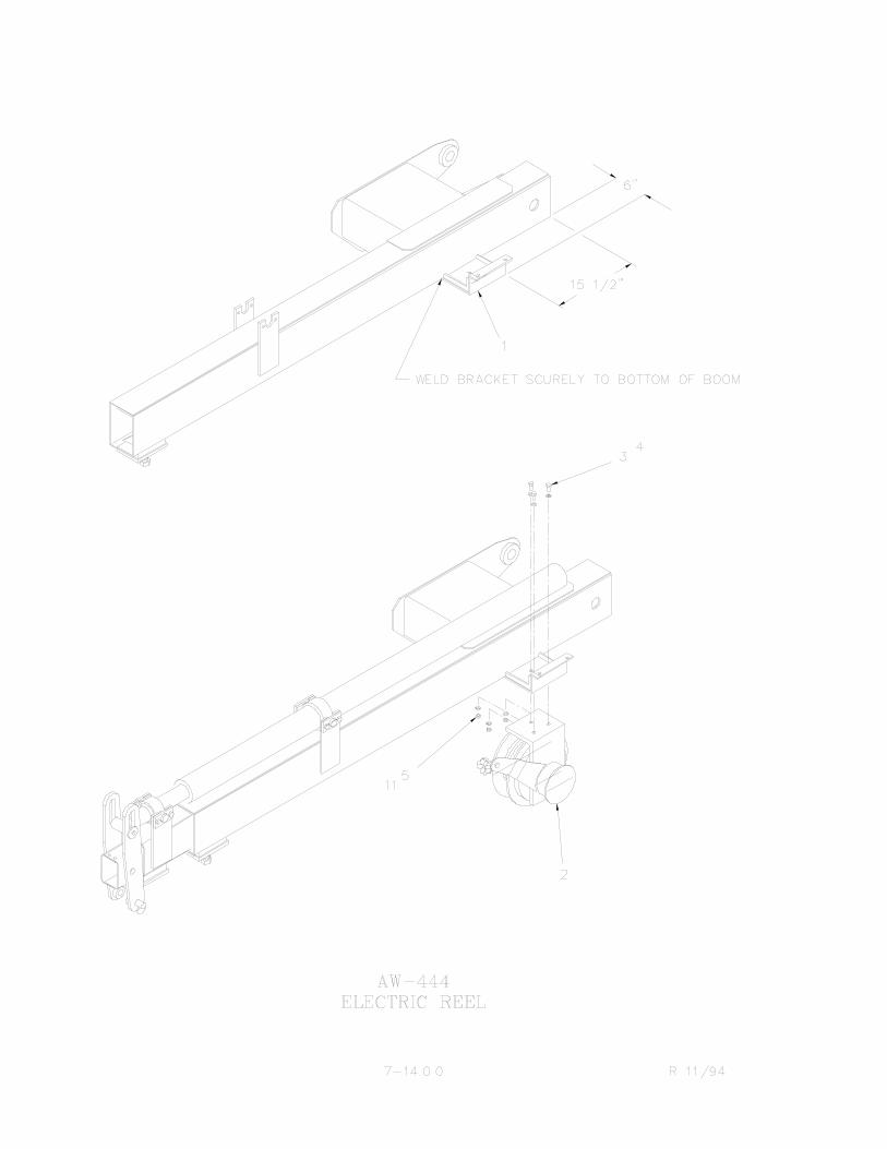


1 System consists of a pressure compensatedproportional flow control valve with inletrelief, directional solenoid control valve,proportional amplifier, and a hand held
pendant.
2 System has two operational modes; (1)manual control (2) pendant control.
3 Manual control is obtained when thependant is not plugged into the system or ifpendant is plugged into system and theon-off power switch is in the off position,
allowing manual control of directionalsolenoid control valve. In this mode, theswitching relays turn the proportional flowcontrol valve full on allowing all hydraulicflow and pressure to be directed to the direc-
tional solenoid control valve.
4 Pendant control is obtained when thependant is plugged into the system and thependant on-off power switch is in the onposition, allowing pendant control of cranefunctions only. When pendant on-off switchis turned on, power is applied to the direc-
tional solenoid control valves
KNUCKLEBOOM PROPORTIONAL SYSTEM"HOW IT WORKS"
DIN POWERSWITCHINGRELAY
RELAYSWITCHINGDIN GROUND
POWERRELAY
PROPORTIONALAMPLIFIER
22 STATION
TERMINAL STRIP
8-SECTION DIRECTIONAL SOLENCONTROL VALVE
DIN CONNECTOR
PROPORTIONACONTROL
VALVE
PENDANTRECEPTACLE
RECEPTACLEPENDANT
A50AHOW8-1.0.0
FIG. 1

power build-up section, proportional ampli-fier, proportional flow control valve, andpower relay. The power relay, (whenpowered up) deactivates switching relaysthus allowing pendant control of cranefunctions only. In this mode, hydraulic flowand pressure will flow from the pumpthrough the proportional flow control valvedirectly to tank (minimum crane speed) untilpendant trigger is pulled. Pulling triggerincreases voltage to the amplifier thatregulated the proportional flow control valvethus diverting less hydraulic flow andpressure to tank and directing more flowand pressure to the directional solenoidcontrol valve (maximum crane speed).
5 The proportional flow control valve variesthe speed of the crane proportionally by theamount of current sent to it's coil by theproportional amplifier. With no currentapplied to the coil (trigger released), theproportional flow control valve is turned off.This directs full flow and pressure to tank(minimum crane speed). With maximumcurrent applied to the coil (trigger pulled),the proportional flow control valve is turnedfull on. This directs full flow and pressure tocrane (maximum crane speed).
6 The directional solenoid control valve is aneight section valve, with manual and on-offsolenoid controlled valve sections, a powerbuild-up section, and inlet relief valve. Themanual sections typically control outriggersand some optional functions. The solenoidsections only control crane functions. Thepower build-up section provides hydraulicpressure to the solenoid valve sections toactuate the control valve spool(s). The inletrelief valve sets system pressure (2600 PSI).
7 The digital control pulse width modulatorproportional amplifier controls the
proportional flow control valve whichregulates the speed of the crane. The ampli-fier takes an input command voltage frompendant trigger and produces a linearcurrent output which is pulse widthmodulated, to the proportional flow controlvalve's coil. The output is capable of driving10 amps. maximum while maintainingminimal heat build-up. The pulse widthmodulation along with an integrated"Dither" circuit providing high efficiencyand stability. The "Dither" is an oscillatingmovement of the valve that lessens thetendency of the valve to "stick" whencommanded to move, thus providing smoothvalve operation.
8 The pendant is a hand held control stationwith 40 feet of cable which will allow anoperator to control the crane's movementand speed remotely. The pendant consists offour 3-position momentary switches whichcontrol the crane's movement, two 3-positionmomentary switches which control auxiliaryequipment, one 3-position momentary switchwhich controls engine start-stop, one2-position maintained on-off switch whichcontrols power to system, one potentiometer(trigger) which is used to vary the controlvoltage to the amplifier when the trigger ispulled. The pendant switches control whichcrane function is activated and the triggerwill control crane speed. Always select cranefunction first then pull trigger to get thedesired crane speed.
9 DIN ground switching relay, switches theground control of the proportional flowcontrol valve from the amplifier to grounddepending on the mode of operation. In themanual mode the relay is activated whichprovides ground to the DIN connector.While in the pendant mode the relay isdeactivated, which allows the amplifier's
KNUCKLEBOOM PROPORTIONAL SYSTEM"HOW IT WORKS"
8-1.1.0 A50AHO

out-put to control the proportional flowcontrol valve. Note: The amplifier sinksground for the proportional flow controlvalve.
10 DIN power switching relay, switches thepower source of the proportional flowcontrol valve. In the manual mode relay isactivated which provides 12 VDC fromterminal #14 to the proportional flow controlvalve's DIN connector. While in the pendantmode relay is deactivated which provides 12VDC from the power relay to the propor-tional flow control valve's DIN connector. Inboth manual and pendant modes the DINconnector is always powered when themaster switch is on (12 VDC nominal, atterminal #14).
11 Power relay is activated by the pendanton-off switch. In the manual mode, powerrelay is deactivated which activates both DINswitching relays. While in the pendant modethe power relay is activated which powers upthe power build up section, proportionalamplifier and proportional flow controlvalve's DIN connector.
12 To manually override the proportional flowcontrol valve, screw in (clockwise) themanual override located on the coil atproportional flow control valve. This will
allow full flow and pressure to the direc-tional solenoid control valve (maximumcrane speed). Note: screwing manualoverride in half way allows half flow andpressure to tank and half flow and pressureto crane (half crane speed). manual overrideshould only be used when there is a problemwith proportional amplifier, switchingrelays, and or 12 VDC source.
PRESS. OUTCPRESS. INP
TO TANKT
MANUALOVERRIDE SCREW
13 Master control switch mounted in truck cabcontrols the power to proportional system.Master switch should be a two positionmaintained on-off switch. When masterswitch is on, 12 VDC is applied to terminal#14, turning proportional system on, while inthe off position the proportional system isturned off. Note: master switch should beconnected to a circuit which is hot only whentruck ignition is in the on position.
KNUCKLEBOOM PROPORTIONAL SYSTEM"HOW IT WORKS"
8-1.2.0
A50AHOW
FIG. 2

HYDRAULIC
1 Pressure hose from pump to proportional flowcontrol valve inlet specifications. Hose size: -10 (SAE100R2 TYPE AT) at desired length. Hose endfittings: -12 JIC female swivel, both ends. Connectpressure hose at proportional flow control valve only.
2 Return hose from directional solenoid control valve toreturn filter and return filter to reservoir. Hose size:-12 (SAE 100R2 TYPE AT) at desired length. Hoseend fittings: -12 JIC female swivel, both ends. Connect return hose at either the directional solenoidvalve or the proportional flow control valve returnports.
ELECTRICAL
1 Connect chassis ground wire (black wire of 16/2conductor power cable) to chassis. This will providethe ground for the knuckleboom proportional system.
2 Connect power wire (white wire of 16/2 conductorpower cable) to a master switch mounted in truckcab. Master switch should be a two positionmaintained on-off switch, which is connected to anelectrical circuit that is hot only when the truckignition key is in the on position.
HYDRAULIC AND ELECTRICALHOOKUPS
Hydr Elect 9/94
PRESS. OUTCPRESS. INP
TO TANKT
IN
OUT
PORPORTIONING VALVETO PORT "C" OF
TO PORT "T" OFPORPORTIONING VALVE
RETURN TO TANK
RETURN TO TANK
(CAP IF NOT USED)
(CAP IF NOT USED)
8-2.0.0
FIG. 3

NOTES

1 Make sure all crane operating personnel havethoroughly read and understood the informationcontained in this manual. Crane to be operated byqualified personnel only.
2 A routine daily inspection of the crane should bemandatory before each operating day. Any defectsshould be corrected immediately before operating thecrane.
3 At a job site the vehicle should be positioned so that thecrane can adequately reach the load within the ratedcapacity (centerline of rotation to hook). Job site shouldhe checked for any hazards which might create anunsafe situation for the operator; such as any overheadelectrical lines, underground electrical lines, anyelectrical source(s), soft or uneven ground, and anyunauthorized personnel who might enter the job site.When cross grade parking is necessary, restrict theload to compensate for the increased tipping risk of thevehicle.
4 Keep vehicle as level as possible during operation.5 Chock rear wheels, engage emergency brake, place
gear selector into neutral, press clutch and PTO knobin gear, release clutch and set throttle control to properengine speed.
WARNING: DO NOT EXCEEDENGINE SPEED NECESSARY TOMEET PUMP RPM REQUIREMENT(see hydraulic section) POSSIBLEDAMAGE MAY RESULT.
6 System has two operational modes:
A.Manual control: In the manual mode, thependant is either not plugged into system oris plugged in with on-off power switch inthe off position. The operator will havemanual control of all crane functions,outriggers, and auxiliary valve sections.
B. Pendant control. In the pendant mode, thependant is plugged into the system with theon-off power switch in the on position. Theoperator will have control of all cranefunctions and auxiliary valve section.
7 Using crane in the manual mode set outriggers.Always use outriggers from crane to the ground.
Be sure outriggers are in firm contact with ground andare adequately positioned.
8 Plug pendant into one of the receptacles located oneither side of the crane base and turn pendant powerswitch to the on position. To operate pendant properlyalways select the crane function you want to use (i.e.inner boom up) first with the pendant trigger releasedand then pull pendant trigger to get the desired cranespeed.
9 Un-stowing knuckleboom; first begin by retractingouter boom cylinder which raises the outer boom up inthe ramp and purges any air out of the outer boomcylinder, extend lift cylinder to raise inner boom. Onceinner boom is clear of the base then knuckleboom canbe rotated into a work ready position. Always raiseinner boom up before rotating.
10 Always observe safe and practical operation to avoidpossible accidents. Refer to safety tips and precautions.
11 After completing lifting operations return the knuckle-boom into figure four position for travel. Whenstowing, begin by:
A.Retracting the extension cylinder.B. Retracting outer boom cylinder.C.Rotating crane into position by aligning the
rotation arrows up on the rotation bearingand base plate.
D.Retract lift cylinder to lower inner boominto figure four position.
E. Extend outer boom cylinder, which lowersthe outer boom assembly into ramp.
Always stand on opposite side of inner boom whenstowing or unstowing.
12 Turn pendant power switch to the off position; thisreturns the crane to the manual mode.
13 Return outriggers to stowed position. Make sure theyare pinned in place (if required) for travel.
14 Remove and store pendant in proper location. Neverleave pendant plugged into system when not in use.
15 Check job site for any tools or equipment not stored.Store all wheel chocks.
16 Press clutch and disengage PTO. Release throttlecontrol, and emergency brake.
17 Report any unusual occurrence during crane operationthat may indicate required maintenance or repair.
OPERATION OF KNUCKLEBOOM WITHPROPORTIONAL REMOTE CONTROL
PRC R9/948-3.0.0


KNUCKLEBOOM PROPORTIONAL PENDANTTRIGGER POTENTIOMETER SETUP PROCEDURE
8-6.0.09/94
1 Position the truck with crane in a safe workarea. Using hand levers on the control valve,extend outriggers out and down, unfoldbooms, rotate crane until booms are directlyover bed of truck.
2 Remove amplifier terminal block coverlocated on the base of crane.
3 Plug pendant into one of the receptacleslocated on either side of crane.
4 Turn power on.5 Check the output voltage of the pendant
trigger potentiometer with trigger pulled,voltage output should be 3.0 to 9.0 volts onterminal #21. Check with trigger released,voltage output should be 0.4 to 0.6 volts onterminal #21. If trigger potentiometer outputfalls in the voltage range specified no otheradjustment to the pendant triggerpotentiometer is required. If triggerpotentiometer output does not fall within thevoltage ranges specified continue with setupprocedure.
6 Remove four (4) screws which hold pendantback plate on, and remove back plate.
7 Make sure potentiometer's mounting nut istight.
8 Loosen (do not remove) the 5/32" allen headcap screw that locks the trigger in place.
9 With trigger released, turn the potentiometershaft full counterclockwise with a screwdriver,then slowly turn shaft clockwise to achieve 0.4to 0.6 volts on terminal #21.
NOTE: CARE SHOULD BE TAKENWHEN HANDLING THEPOTENTIOMETER ASSEMBLY TOKEEP FROM BREAKING THE WIRESAT THEIR ATTACHMENT POINTS.
Tighten the allen head screw using a 5/32"allen wrench (DO NOT OVER TIGHTEN).This screw need only be set firmly againstpotentiometer shaft. Trigger damage willresult from over tightening. Retest voltage onterminal #21.
10 Fully pull trigger and verify that there is 3.0 to9.0 on terminal #21.
11 Slowly pull trigger through a full cycle (fullyreleased to fully pulled) to verify consistentsmooth voltage change at terminal #21.Replace potentiometer assembly if voltagechange is not smooth.
12 Replace pendant and amplifier-terminal blockcovers.
13 Stow crane, turn power "OFF", unplug andstore pendant.

1 Position the truck with crane in a safe work area.Using hand levers on the control valve, extendoutriggers out and down, unfold booms, rotatecrane until booms are directly over bed of truck.
2 Remove amplifier terminal cover screws and liftoff cover.
3 Plug pendant into one of the receptacles locatedon either side of the crane base and turn poweron. With pendant trigger pulled; adjust the smalltrim pot located next to the red L.E.D. light untillight just turns off, then turn trim pot back untillight just comes on. The light should stay onduring full trigger movement. Clockwise rotationof trim pot will turn light off. Counter-clockwiserotation will turn light on. This procedure"tunes" the amplifier to the triggerpotentiometer.
4 Set the low voltage dial, activate any one cranefunction (rotate uses the least amount ofpressure) with trigger released. Turn the lowvoltage dial (ref. figure 7, dial marked "L" oncircuit board) until there is no movement of thatfunction. With crane level and no load on booms,check rotation, inner boom down, outer boomdown, and extend out functions for anymovement. Note; in the pendant mode withtrigger released there should also be no cranemovement when a control valve hand lever isactivated. If there is movement, adjust amplifiers
low voltage dial until there is no movement. The"0" and the "F" on the dial are opposite ends ofthe low voltage dial. Turning dial clockwisedirection increases movement whilecounter-clockwise direction stops movement.This procedure adjusts the "threshold" speed forthe trigger in the released position.
5 Set the high voltage dial with inner and outerbooms horizontal, boom sections retracted.Activate inner boom up function with triggerpulled back to maximum position. Whilewatching boom up speed, turn the high voltagedial (ref. figure7, marked with "H" on circuitboard) until there is a noticeable decrease inspeed, then back-up one or two clicks as desired.The "0" and the "F" on the dial are oppositeends of the high voltage dial. Turning dialclockwise direction decreases speed whilecounterclockwise direction increased speed. "0"is the maximum speed setting and "F" is themost reduced speed setting. This procedureadjusts the trigger "dead band" at the fully pulled position.
6 The proportional amplifier's high and lowvoltage dials should not be set on "F". Settingboth high and low voltage dials on 4 as a goodstarting point.
7 Stow crane, replace covers, turn power off,unplug and store pendant.
KNUCKLEBOOM AMPLIFIER SETUPPROCEDURE
A50AAMP R7/96
Amplifier Setup 8-7.0.0

HAND HELD PENDANT ASSEMBLY1. With ignition key in the "ON" position, hand held
pendant assembly plugged into system, and pendantpower on-off switch in the "ON" position;
A.Check pendant trigger signal voltage atterminal #21. Voltage should be 3.0 to 9.0volts when pendant trigger is pulled, 0.4 to0.6 volts when pendant trigger is released.
B. Test trigger potentiometer output voltage atterminal #21 for consistent smooth voltagechange when trigger is pulled. NOTE: for Aand B reference pendant trigger potentiome-ter setup procedure.
2. Check pendant trigger for damage which may haveoccurred from over tightening of set screw.
3. Verify all wiring to pendant switches is correct andthat there are no loose connections.
PROPORTIONAL FLOW CONTROL VALVE
1. Check voltage at terminals #13, #14, #15.
A.Terminal #13 voltage should be 12 VDCnominal when pendant is plugged intosystem and the on-off power switch isturned to the "ON" position.
B. Terminal #14 voltage should be 12 VDCnominal when master switch is in the "ON"position.
C.Terminal #15 voltage should be 12 VDCnominal when there is 12 VDC at terminals#13 and #14.
2. With 12 VDC nominal applied to terminal #15,disconnect brown wire from DIN connector (groundbrown wire) to shift proportional valve full on.
3. Measure proportional flow control valve's coil resis-tance; turn ignition key and master switch to the"OFF" position to remove power from proportionalsystem. Disconnect brown and blue wire bulletconnectors from proportional flow control valves coil. Measure resistance between brown and blue bulletconnectors. Coil resistance should be 4.5-5.5 ohms. Ifresistance is outside that range, replace coil.
4. To check hydraulic flow to crane:
A.Engage PTO-pump, turn manual overrideclockwise to divert pressure and flow todirectional control valve. Crane shouldoperate manually.
B. Place flow meter in the tank line from theproportional flow control valve. Measureflow with pendant plugged in and systemturned on, trigger released. Flow to tankshould be 9-13 gpm, depending on model ofcrane. As trigger is pulled, flow shouldsmoothly decrease to 0 gpm.
1
5. Measure voltage drop across proportional flowcontrol valve's coil. Voltage may be measured using adigital volt-ohm meter set to volts. Check voltagebetween terminal #15 and the bullet connector, withthe pendant plugged in and turned on. The bulletconnector is the connector on the brown wire of theDIN connector from proportional flow control valve'scoil. IMPORTANT: Bullet connector must remainconnected when taking voltage readings. Voltage dropshould be 12 VDC nominal with pendant triggerpulled to less than 1 VDC nominal with pendanttrigger released. Note: to register these readingssystem must be turned on, (i.e., with red L.E.D. lighton). The settings of the amplifier's high and lowvoltage dials affects both the 12 VDC and 1 VDCnominal voltage readings across the coil of theproportional flow control valve. Normally, both thehigh and low voltage dials are adjusted to 4.
TROUBLE SHOOTING PROPORTIONALCONTROL SYSTEM
9/948-9.0.0
FIG. 8

PROPORTIONAL AMPLIFIER1. With ignition key in the on position and hand held
pendant assembly plugged into system and pendantpower on-off switch in the "ON" position;
A.Check amplifier input voltage at terminal#15. Voltage should be 12 VDC nominal.
B. Check pendant trigger signal voltage atterminal #21; voltage should be 0.4 to 0.6volts when trigger is released. Referencependant trigger potentiometer setup proce-dure.
C.Check to make sure L.E.D. light, which isnext to small trim pot is on. If light is noton, adjust proportional amplifier (refer-ence knuckleboom amplifier setupprocedure).
2. Check ground at terminals #16, #17, #18. 3. Check in line fuse from proportional amplifier to
terminal #18. 4. Make sure bullet connectors leading from the DIN
ground switching relay assembly to proportional flowcontrol valve and amplifier are connected.
5. The proportional amplifier's high and low voltagedials should not both be set on "F".
6. Check voltage output of the proportional amplifier.Voltage may be measured using a digital volt-ohmmeter set to volts (see figure 9). Check voltagebetween ground and the amplifier's output buttconnector. The butt connector is located between theDIN ground switching relay assembly's green/blackwire and the amplifier's green output wire. Voltageoutputs should be 12 VDC nominal with pendanttrigger released, down to 3 VDC nominal withpendant trigger pulled. To register these readings,system must be turned on, pendant trigger potenti-ometer voltage must be correct and amplifier must beturned on with red L.E.D. light lit. The setting of theamplifier's high and low voltage dials affects both the12 VDC and 3 VDC nominal readings. Amplifier'shigh voltage dial affects 3 VDC nominal reading,(trigger pulled) while low voltage dial affects 12 VDCnominal reading (trigger released).
9/94
TROUBLE SHOOTING PROPORTIONALCONTROL SYSTEM
FIG.9
8-9.1.0

The Auto Crane FM proportional controlsystem consists of a transmitter and receiverunit. The system operates on the 5 RFchannels in accordance with FCC subpartD-low power communications devices, part15.117. Use of this device is subject to theprovisions of FCC part 15.103. A license isnot required to operate this system.
TRANSMITTER
The transmitter generates a RF signal whichis FM modulated. The modulation is a 120 bitdata stream with start and stop bits, informa-tion concerning the selected switch beingactivated and a specialized algorithm devel-oped to ensure the validity of thetransmission. Also transmitted are
address information to enable it to "talk" to itsassociated receiver. This address informationis set at the factory so no two devices will bethe same. There can be over 20,000 units inthe same vicinity without any cross activation.Each unit's address code has been preset atthe factory. It is advised not to change codeswithout first consulting the factory. The trans-mitter is powered by a disposable 9 voltbattery. Use of a Ni-Cad battery is not recom-
mended because the operating time is greatlyreduced. To install the 9 volt battery, removethe battery cover on the rear of thetransmitter. Removal of the battery cover iseasily achieved by releasing the latch clip.Care should be taken not to use excessiveforce to prevent damage to the cover. Insert
FM PROPORTIONAL GENERAL INFORMATION
FIG. 10
8-11.0.0A50AFMNFO R11/94

the battery making sure the polarity of theterminals are correct.
RECEIVER
Receiver receives a the signal transmitted bythe transmitter, decodes the data stream andchecks for validity of the address and the startand stop bits of the received data. If this iscorrect, a proprietary software algorithm isperformed to accept or reject the informationto be passed on to the outputs. If for anyreason this test fails, no output will be allowedto function. Once this test has passed, theappropriate output will be activated.
RECEIVER CONNECTOR INSTRUCTIONS
Insert a small straight blade screwdriver intothe square hole of the desired pin. Pryingtowards the face (lid) of the receiver, insert orremove the appropriate wire directly belowscrewdriver. Release the screwdriver and theconnection is complete. strip all wires to beinserted into the 20 pin connector to a lengthof 3/8" to 1/2" long. Wires should be tinned forease of installation. There are three (3) inputsto the receiver; BNC connector Positive D.C.current Negative ground The unit derivespower from a 12 vdc nominal power sourcethat is negative ground. First hook up powerinputs to receiver. It is required to install apower switch for the receiver in series (in-line)with the D.C. power system (battery).
INITIALIZING UNIT
When initially using the radio remote controlsystem, turn power on the receiver first. Thisallows power to the micro processor andawaits for a special code from the transmitterto activate a relay to make power available tothe output driver circuit. When the
transmitter is turned on, it will transmit aspecial code for 10 seconds to instruct thereceiver to initialize. This will happen only ifthe transmitter is not transmitting a functionsuch as a switch being activated. During thisinitial 10 seconds a function may be activatedonce the receiver has been initialized. Theinitialization is instantaneous so operator willnot have any delay in operation. If the trans-mitter is "out of range" or a function isactivated when the transmitter is turned on,the receiver will not be initialized. Once thereceiver has been initialized, the unit will beallowed to operate.
EMERGENCY KILL FUNCTION
Each transmitter is equipped with anemergency kill switch located near theantenna which when activated will "shutdown" the receiver and stop truck engine.This must be activated while transmitterpower is in the "on" position. This specialcode will be transmitted for a period of 10seconds. when the receiver receives thisspecial code, the power to the output drivercircuit will be de-activated. To resume opera-tion, the transmitter must again send thespecial code to re-activate the receiver. Toachieve this, turn transmitter power off andback on. The transmitter will again go throughits routine to initialize the receiver pleaseinstruct your operators how to use the"emergency kill" and insist that they operatethis feature to become familiar with theoperation.
ADDRESS CODES
Each transmitter and receiver's address codeare unique and preset at factory. We advisethat the codes not be changed without firstconsulting the factory. There are two featuresin our system that the end user can change to
meet their growing needs. On the receiver
FM PROPORTIONAL GENERAL INFORMATION
8-11.1.0A50AFMNFO R11/94

board there are two banks of eight dipswitches, (refer to fig. 11). Bank "A" controlsoutputs 1 thru 8. Bank "B" controls outputs 9thru 16. When switches are in the off positionthese outputs will be momentary. Note:
momentary switches require constantpressure on transmitter switch to operateeach output. If the receiver utilizes standardsoftware, and any switches are in the "ON"position the outputs will be latched. Latchdoes not require operator to maintainpressure on the transmitter switch to operate,i.e. common ON/OFF function such as turninglights ON and OFF. To change these switchesyou must remove the receiver enclosure lid.Since receiver is a proportional unit, there aretwo (2) hex switches which are labeled LowEnd proportional and High End Proportional.On this style of unit, master control output willbe a pulse width modulated (PWM) signal.The Proportional Low End Switch sets thePWM output to the proportional value's lowend setting, (see fig.11). The ProportionalHigh End Switch sets the PWM output to theproportional valve's high end setting, (see fig.11). The independent proportional low andhigh end settings match the potentiometer
travel with the proportional valve's workingvoltages.
Care should be taken in installing thereceiver's antenna. When mounting antenna,keep in mind that the unit comes standardwith ten feet of antenna cable. If driving anelectric over hydraulic pump or any type of electric motor, mount the antenna away fromthe motor since they may emit spurious inter-ference. This will reduce the possibility ofelectrical interference. For best operation,pick a location that has good visibility and aground plane with a diameter that is at leasttwice the height of the antenna. Note; it isimportant that any excess antenna cable notbe wrapped in loops. The connector on theend of the cable will hook up to the antennaconnector on receiver.
FM PROPORTIONAL GENERAL INFORMATION
8-11.2.0
Fig. 11
FMPropR11/94
Fig. 12

MASTER SWITCH
Master control switch mounted in truck cab isa lighted three position, (ON-OFF-ON),maintained single pole double throw switchwith five terminals. Master control switchshould be connected to a truck circuit whichwill supply 12 vdc nominal only when truckignition is in the ON position. When masterswitch is flipped into the manual modeposition, 12 vdc will be supplied to #18 termi-
nal on terminal strip which turns proportionalvalve full on thus allowing manual control ofcrane. With master switch flipped into the FMmode position, the power relay is activatedwhich turns both the receiver and the powerbuilt-up section "ON".
PROPORTIONAL VALVE
Pressure compensated proportional flowcontrol valve with inlet relief, varies the speedof the crane proportionally by the amount of
current sent to its coil by the receiver. With nocurrent applied to its coil (transmitter triggerreleased), the proportional flow control valveis turned off. This directs full flow andpressure to tank (minimum crane speed).With maximum current applied to its coil(transmitter trigger pulled), the proportionalflow control valve is turned full "ON". Thisdirects full flow and pressure to crane(maximum crane speed). Note; in order to geta master control output signal from the
receiver, both a transmitter output and thetransmitter trigger must be activated simulta-neously. Simply pulling trigger without activat-ing a transmitter output will not get a mastercontrol output signal. Always select a trans-mitter output you want to use (i.e. inner boomup) first with transmitter trigger released andthen pull transmitter trigger to get desiredmaster control output (crane speed). Thereceiver's master control output "sources" theproportional flow control valve's coil.
FM PROPORTIONAL SYSTEMHOW IT WORKS
FIG.13PROPORTIONAL VALVE HOOK-UP
8-12.0.0 FMPropWork 11/94

NOTES

TRANSMITTER
Transmitter is a hand held controller whichcontrols the speed and functions of craneusing transmitted radio frequencies. Thisallows the operator to have complete controlof crane at an optimum distance form loadbeing lifted. The transmitter controls innerboom, outer boom, extension, rotation, auxil-iary 1, auxiliary 2, start-stop, fast/slow
idle-manual mode, emergency stop, andmaster control output signal. The transmitteroutput switches control which crane functionis activated while pulling trigger increases themaster control output signal which increasesspeed of crane.
FM PROPORTIONAL SYSTEMHOW IT WORKS
FIG. 14FM TRANSMITTER
8-12.1.0 FMPropWork 11/94

1 Make sure all crane operating personnelhave thoroughly read and understoodthe information contained in thismanual. Crane to be operated by quali-fied personnel only.
2 A routine daily inspection of the craneshould be mandatory before eachoperating day. Any defect should becorrected immediately before operatingthe crane.
3 At a job site the vehicle should bepositioned so that the crane can beadequately reach the load within therated capacity (centerline of rotation tohook). Job site should be checked forany hazards which might create anunsafe situation for the operator suchas overhead electrical lines, under-ground electrical lines, any electricalsources, soft or uneven ground, andany unauthorized personnel who mightenter the job site. When cross gradeparking is necessary, restrict the load tocompensate for the increased tippingrisk of the vehicle.
4 Keep vehicle as level as possible duringoperation.
5 Chock rear wheels, engage emergencybrake, place gear selector into neutral,press clutch and PTO knob in gear,release clutch and set throttle control toproper engine speed.
WARNING: DO NOT EXCEEDENGINE SPEED NECESSARY TOMEET PUMP RPM REQUIREMENT,POSSIBLE DAMAGE MAY RESULT.
6 System has two operational modes: 1.)manual control 2.) FM control. In the
manual mode operator will have manualcontrol of all crane functions,outriggers, and auxiliary valve sections.While in the FM mode, operator willhave control of crane functions only.There are two ways an operator mayselect to operate crane in the manualmode; First, move master control switchin cab into the manual mode position.Second, move master control switchinto the FM mode position, turn trans-mitter power on and activate transmittermanual mode switch. NOTE; While inthis mode the operator will have manualcontrol of crane until any transmitteroutput function is activated which willautomatically switch transmitter frommanual control to FM control. Tooperate crane in the FM mode movemaster control switch into the FM modeposition, turn transmitter power on, theoperator will have control of cranetransmitter only. The hand held trans-mitter will operate all crane functionsexcept outriggers.
7 Begin by selecting FM mode mastercontrol switch, turn transmitter poweron, activate the manual mode switch onthe transmitter, this will allow manualcontrol of crane to set outriggers.Always use outriggers from crane to theground. Be sure outriggers are in firmcontact with ground and are adequatelypositioned. Once outriggers have beenproperly set, the operator may continueto operate the crane in the manual modeor may choose to operate crane in theFM mode. To switch crane to FM modethe operator may de-activate transmittermanual mode switch or activate anytransmitter output function. To operateFM transmitter properly always selectthe crane function you want to use (i.e.
inner boom up) first with the
OPERATION OF KNUCKLEBOOM WITHFM PROPORTIONAL REMOTE CONTROL
8-13.0.0 FMPropOp 11/94

transmitter trigger released and thenpull transmitter trigger to get desiredcrane speed.
8 When unstowing knuckleboom crane,first begin by retracting outer boomcylinder, which raises the outer boomup in the ramp and purges any air out ofthe outer boom cylinder. Extend liftcylinder to raise inner boom. Once innerboom is clear of the base, the crane canbe rotated into a work ready position.Always raise inner boom up beforerotating.
9 Always observe safe and practicaloperating practices to avoid possibleaccidents. Refer to "SAFETY TIPS ANDPRECAUTIONS".
10After completing lifting operations,return the booms to the figure 4 positionfor travel. When stowing, begin byretracting the extension cylinder.Retract outer boom cylinder. Rotatecrane into position by aligning up therotation arrows on the rotation bearingand base plate. Retract lift cylinder to
lower inner boom into the figure 4position. Always stand on the oppositeside of the inner boom when stowingand unstowing.
11Once the crane has been properlystowed, return FM system to manualmode and return out outriggers to thestowed position. Make sure outriggersare pinned in place (if required) fortravel.
12Turn both the transmitter power switch,and the master control switch (in cab) tothe "OFF" position. Never leave trans-mitter on, and always store transmitterin proper place when not in use.
13Check job site for any tools or equip-ment not stored. Store all wheel chocks.
14Press clutch and disengage PTO.Release throttle control and emergencybrake.
15report any unusual occurrence duringcrane operation that may indicaterequired maintenance or repair.
OPERATION OF KNUCKLEBOOM WITHFM PROPORTIONAL REMOTE CONTROL
FMPropOp 11/948-13.1.0


GENERAL
Whenever there is a problem with the systembegin by first checking the fuse in the receiverand then checking all wiring and connectors.Look for dead shorts in wiring andconnections, or run a new cable from theoutputs of the receiver directly to solenoidsand then try radio system. maximum 12 to 15amp fuse in receiver.
TRANSMITTING RANGE DROPS ORINTERMITTENT MOVEMENT OCCURSWHEN ACTIVATING A FUNCTION
1 Make sure the 9 volt battery in thetransmitter is good.
2 Be sure the antenna is free of verticalmetal obstruction.
3 Any excess antenna cable should notbe coiled together.
4 Check antenna cable connector at thereceiver. Be certain the antenna isproperly installed and that there isnothing touching the bare portion ofwires at the antenna connection.
IF UNIT FAILS COMPLETELY OR IF ONLYONE OR TWO OUTPUTS ARE NOTWORKING
1 Remove cover on the receiver and referto fig. 9.
2 With power to the receiver, the powerindicator LED will be on. Turn transmit-ter power on. At this time the receiver'sRF indicator LED will be on for 10seconds and the sound of the powerrely engaging will be heard. Anytimeafter transmitter power is on a
function may be activated. To verifythat the power relay is engaged andthat the transmitter is transmitting,activate the emergency stop on thetransmitter. This will disable the powerrelay and the transmitter will transmitfor 10 seconds. The RF and powerindicator LED's will be on. To reset thereceiver and transmitter, turn the trans-mitter power off and back on. At thistime the receiver's RF indicator LEDwill be on for 10 seconds and the powerrelay will engage.
3 When a function is activated on thetransmitter, three LEDs are "ON" in thereceiver. RF indicator LED.
4 Output status indicator LED (functionactivated).
5 Master control LED. (the power indica-tor LED is always on.
6 With power rely engaged, check eachfunction by activating each toggleswitch. Make sure each of thereceiver's output status indicator LEDsturn on.
POWER RELAY DOES NOT ENGAGE
Address codes may not match. Compare the12 position address switches in bothtransmitter and receiver. If they both matchand still the power relay doesn't engage set all12 of the dip switches to the off position inboth the receiver and the transmitter. At thispoint if the radio controller works or not, callthe factory to either be assign a new addresscode or to have the radio controller shippedback to the factory for repair.
AFTER FACEPLATE HAS BEEN REMOVEDFROM THE TRANSMITTER AND
FM PROPORTIONAL CONTROL SYSTEMTROUBLESHOOTING
8-16.0.0 FMPropTS 11/94

REINSTALLED, UNIT DOES NOT OPERATEPROPERLY
1 Remove faceplate from transmitter.Make sure that leads to each leadscrew on toggles are secure and willnot be at an angle where it would betouching anything when replacing thefaceplate.
2 Disconnect wiring harness from PCboard and then reconnect the sameway. Be sure that no wires are loose atconnector and that connector is secureon connector pins. The wiring harnessshould be positioned between togglehousings or in a location so as not tobecome pinched upon reassembly.
EXAMPLE TO FOLLOW ON EXISTINGEQUIPMENT
1 Activate a function on the transmitterthat will not cause a hazardous situa-tion. At this time the receiver's RFindicator LED and the appropriateOutput Status Indicator LED will be on.If the function activated does not occur,check the following:
A. Be sure that the appropriate orangeconnector pin matches the OutputStatus Indicator LED. There shouldbe 12 vdc to that output. If there ispower to the output, the n the wiringand hydraulic system should bechecked.
B. If the appropriate Output StatusIndicator LED is turned on and thereis no power to the orange connectorpin, consult the factory.
FM PROPORTIONAL CONTROL SYSTEMTROUBLESHOOTING
8-16.1.0 FMPropTS 11/94

NOTES

1 Position the truck with crane in a safe workarea. Using hand levers on the control valve,extend outriggers out and down, unfoldbooms, rotate crane until booms are directlyover bed of truck.
2 Set the low voltage dial, activate any onecrane function (rotate uses the least amountof pressure) with trigger released. Turn thelow voltage dial (ref. figure 15, dial marked"L" on circuit board) until there is nomovement of that function. With crane leveland no load on booms, check rotation, innerboom down, outer boom down, and extendout functions for any movement. Note; in thependant mode with trigger released thereshould also be no crane movement when acontrol valve hand lever is activated. If thereis movement, adjust amplifiers low voltagedial until there is no movement. The "0" andthe "F" on the dial are opposite ends of thelow voltage dial. Turning dial clockwisedirection increases movement whilecounter-clockwise direction stops movement.
This procedure adjusts the "threshold"speed for the trigger in the released position.
3 Set the high voltage dial with inner and outerbooms horizontal, boom sections retracted.Activate inner boom up function with triggerpulled back to maximum position. Whilewatching boom up speed, turn the highvoltage dial (ref. figure 15) until there is anoticeable decrease in speed, then back-upone or two clicks as desired. The "0" and the"F" on the dial are opposite ends of the highvoltage dial. Turning dial clockwise directiondecreases speed while counterclockwisedirection increased speed. "0" is themaximum speed setting and "F" is the mostreduced speed setting. This procedureadjusts the trigger "dead band" at the fully pulled position.
4 Both HIGH & LOW voltage dials should notbe set on "F". Setting both high and lowvoltage dials on 4 as a good starting point.
5 Stow crane, replace cover, turn power off.
FM PROPORTIONAL PROCEDURESETTING HIGH & LOW END
FMPropHiLo 11/948-17.0.0
FIG. 15

9-1.1.0 372030 2/2000
HYDRAULIC ASSEMBLY

9-1.2.0 372030 2/2000
HYDRAULIC ASSEMBLY
Straight Adapter -8 0R(M) / -6 JIC(M)20275614290° Elbow -12 JIC (F) Swivel / -12 JIC367283141Cap Screw ¼ UNC x 1 ¾ 005810640Lock Washer 5/16020601439Socket Head Screw 5/16 UNC x 2 ¼ 367163438Socket Head Screw 3/8 UNC x 2 3/4367164437Lock Washer ¼ UNC020200836Cap Screw ¼ UNC x 1 ½ 005804235Lift Cylinder Hose Assembly812210-061234Outer Boom Hose Assembly812303-152233Extension Hose Assembly812309-225232Streetside Outrigger Hose Assembly812206-108231Curbside Outrigger Hose Assembly812206-145230Rotation Hose Assembly812210-068229Extension Cylinder Tube Assembly372262128Outer Boom Tube Assembly372263127Lift Cylinder Tube Assembly372196126Swing DriveTube Assembly367166125Tee -12 (F) Swivel Nut / -12 JIC750472124Straight Adapter -12 OR(M) / -12 JIC(M)750420223Plug -12 OR(M)750478122Plug -14 OR(M)367204121Plug -10 OR(M)330072420Swivel -10 O-Ring / -8 JIC372195819Cap -12 JIC750419318Flow Restrictor .120367226117Flow Restrictor .047372039216Straight Adapter -4 OR(M) / -6 JIC(M)36714411590° Elbow -4 OR(M) / -6 JIC(M)367140114Straight Adapter -10 OR(M) / -6 JIC(M)202755613Straight Adapter -8 OR(M) / -8 JIC(M)367145812Tee -6OR(M) / -6 JIC RUN200877111Straight Adapter -6 OR(M) / -6 JIC(M)200876610Lift Counterbalance Valve36712219Outer Boom & Extension Counterbalance Valve36712128Outrigger Locking Valve37206627Rotation Counterbalance Valve36712416Control Valve (372010 Manual) (367302 Proportional)REFERENCE15Extension Cylinder37206314Outer Boom Cylinder37206213Lift Cylinder37206112Outrigger Cylinder37206021DescriptionPart NumberQuantityItem


9-4.0.0 Aw372030 9/95

9-4.1.0 Aw372030 9/95

CONTROL VALVEP/N 372010
9-5.0.0 372010 2/2000

CONTROL VALVEP/N 372010
9-5.1.0 372010 2/2000
Inlet Relief Seal Kit367024-0017217Port Relief Service Kit367024-0016216Port Relief Seal Kit367024-0015215Load Plug Seal Kit367024-00141414Seal & Washer Spool367024-00131613Washer Spool Retainer Plate367024-00121612Work Port Relief 2200 psi3692221114-Way 3 Position Valve Section367024-00101104-Way 3 Position Valve Section Cylinder367024-00979Inlet Relief Valve367024-00818Work Port Relief367024-00727Load Check Plug367024-006146Standard Positioner367024-00585Small Pressure O-Ring367024-004184Large Return O-Ring367024-003183Inlet Cover367024-00212Stud Kit367024-00111DescriptionPart NumberQuantityItem

NOTES

GENERAL DIMENSIONSA-50A
10-1.0.08//01

11-1.1.0 372023 2/2000
DECAL LAYOUTA-50A

11-1.2.0 372023 2/2000
DECAL LAYOUTA-50A
Decal Danger “Free Falling Manual Booms“367427234Decal Danger “Failure to Obey—Load Charts“367426433Decal Danger “Failure to Obey—Inspection“367425232Decal Danger “Hoisting Personnel“367424231Decal Danger “Rotating Drive Line“367423230Decal Danger “Electrocution Hazard“ (367421)REFERENCE229Installation Checklist999984128Decal Caution “9 GPM”367213127Decal 5 Way Valve Function (See 372330)372321 See Note
2226
Decal Danger “Stay Clear—Load“ (See 372224)040518 See Note1
125Decal Winch Function (See 372224)372322 See Note
1224
Decal Danger “Winch Warning“ (See 372224)367307 See Note1
423Decal 3M “Auto Crane”368111222Load Chart A-50A372324221Decal 3M Logo368110220Decal A-50A372323219Decal Danger “Scissors Point“040519218Decal Danger “Grease“367243117Decal Danger “Hydraulic Fluid Level“367244116Decal Danger “Stay Clear of Load“040630215Decal Danger “Stay Clear of Boom“367251414Decal Danger “Stay Clear of Boom“040517413Decal Arrow367242412Decal Danger “A Moving Outrigger...“367433211Decal Danger “Serious Crushing Injury“040581210Decal Danger “Outriggers“75901629Decal Danger “An Untrained Operator...“04058028Decal Danger “Setting Up/Stowing“36723927Decal Danger “Electrocution Hazard“36743226Decal Danger “Electrocution Hazard“36724165Decal Danger “Load Line“36724644Decal Danger “Stowing & Unfolding“36725043Decal Danger “Inspect Vehicle...“04057922Decal Control Handle37232021DescriptionPart NumberQuantityItem

NOTES

LOAD CHARTA-50A
12-1.0.0Aw-409 8/01


P.O. Box 580697 * Tulsa, OK 74158-0697
4707 N. Mingo Rd. * Phone (918) 836-0463
LIMITED WARRANTY 2 YEAR PARTS AND LABOR
Auto Crane will warranty to the consumer for a period of (2) years parts and labor from the date of purchase. Each new Auto Crane unit they sell will be free under normal use and service from defects in material and workmanship. Date of purchase will be honored as the date indicated on the Bill of Sale, which must accompany the Warranty Registration and be on file with Auto Crane. Absent a valid Warranty Registration and appropriate documentation, the original date of manufacture, as indicated by the serial number on the product, will be used to determine the effective date of the 2 year warranty. The obligation of Auto Crane under this warranty is limited to the replacement or repair of parts that appear to the manufacturer after review and/or inspection to be defective and paid flat rate labor for replacing defective parts. This warranty does not obligate Auto Crane to bear the travel time charges in connection with the replacement or repair of defective parts. Responsibility for customer's claims arising from misapplication, abuse, misuse or alteration of equipment or parts lies with the distributor or user and no warranty obligation is assumed in these circumstances by Auto Crane. Auto Crane will in no event be liable for any consequential damages or contingent liabilities arising out of the failure of any Auto Crane Product or parts to operate properly. Auto Crane makes no warranty in respect to component accessories, it being subject to the warranties of their respective manufacturers. If field service, at the request of the distributor, is rendered and fault is found not to be with Auto Crane's product, the distributor shall pay the time and expense of the field representative. Claims for service labor or other expenses that have incurred by the buyer without approval or authorization or Auto Crane will not be accepted. When applying for warranty, claims may be handled by contacting your nearest authorized Auto Crane Distributor. All claims are to be filed in writing on an Auto Crane Warranty Claim Form. AUTO CRANE COMPANY IS UNDER NO OLIGATION TO EXTEND THIS WARRANTY TO ANY CUSTOMER FOR WHICH AN AUTO CRANE DELIVERY REPORT FORM HAS NOT BEEN COMPLETED AND ON FILE WITH AUTO CRANE COMPANY
Limited Warranty 2 Years Effective September 2, 2003