
A Tolerance Analysis Method for Rotating Machinery · rotating machinery assembly is the bearing...
7
Procedia CIRP 10 (2013) 77 – 83 Available online at www.sciencedirect.com 2212-8271 © 2013 The Authors. Published by Elsevier B.V. Selection and peer-review under responsibility of Professor Xiangqian (Jane) Jiang doi:10.1016/j.procir.2013.08.015 ScienceDirect 12th CIRP Conference on Computer Aided Tolerancing A tolerance analysis method for rotating machinery Junkang Guo, Jun Hong*, Zhaohui Yang, Yong Wang State Key Laboratory for Manufacturing Systems Engineering, Xi’an Jiaotong University, 99, Yanxiang Road, Yanta District, Xi’an, 710054, China Abstract Rotating machinery is widely used in many fields of engineering. In rotating machinery design, the rotary precision is usually the first issue to determinate. Rotary precision is affected by many factors, such as tolerance design, assembly process and part deformation. In this paper, based on small displacement torsor (SDT) model, the tolerance representation and tolerance analysis was discussed firstly. Then the three dimensional non-repetitive run-out (3D-NRRO) of bearings and the assembly matrix to represent the assembly direction of bearing was introduced to the tolerance analysis. At last, the analysis method taking into account of part deformation is discussed. Keywords: rotating machinery; tolerance analysis; small displacement torsor; 3D-NRRO; assembly process; part deformation 1. Introduction a Rotary precision is the most important issue of the geometric requirements for rotating machinery. The rotary precision has a direct impact to the performances of rotating machinery. It is important to research the formation of rotary precision and investigate the tolerance analysis method to improve the performance of rotating machinery. The ordinary tolerance analysis focus on the high- volume manufacturing, assume that the manufacture parts were interchangeable. However, for the high precision rotating machinery such as the spindle of machine tool, the measurement and adjustment is contained in assembly process. This paper proposed a tolerance analysis method for rotating machinery considering the assembly processing and taking into account elastic displacements caused by force impact. This method mainly based on the small * Corresponding author. Tel.: +86-29-83399517; fax: +86-29-83399528 . E-mail address: [email protected]. displacement torsor, which is used for the modelisation of the geometrical deviation of mechanical parts [1][2]. The design of high precision machine requires consideration of operating performance of bearings and it is a crucial in determining the overall quality. The bearing NRRO is a serious factor for the precision of rotating machinery. Zhaohui Yang et al developed a numerical model of the NRRO based on the relationship of the internal movement and theory of contact elastic deformation [3], which the effects of load have on the contact angle, is taken into account. Several researchers have discussed the tolerance analysis integrated the part elastic deformation and displacement. Samper et al present four models which allow elastic deformation of mechanisms in tolerancing to be taken account [4]. Jeang et al proposed a method for the statistical dimension and tolerance design for mechanical assembly under thermal impact [5]. Pierre et al used dimension chain and thermomechanical tools to controlling clearances at the tip of a high pressure turbine blade [6]. Benichou et al considered thermal expansion of parts integrated within functional tolerancing [7]. © 2013 The Authors. Published by Elsevier B.V. Selection and peer-review under responsibility of Professor Xiangqian (Jane) Jiang Open access under CC BY-NC-ND license. Open access under CC BY-NC-ND license.
Transcript of A Tolerance Analysis Method for Rotating Machinery · rotating machinery assembly is the bearing...
Procedia CIRP 10 ( 2013 ) 77 – 83
Available online at www.sciencedirect.com
2212-8271 © 2013 The Authors. Published by Elsevier B.V.Selection and peer-review under responsibility of Professor Xiangqian (Jane) Jiangdoi: 10.1016/j.procir.2013.08.015
ScienceDirect
12th CIRP Conference on Computer Aided Tolerancing
A tolerance analysis method for rotating machinery
Junkang Guo, Jun Hong*, Zhaohui Yang, Yong Wang State Key Laboratory for Manufacturing Systems Engineering, Xi’an Jiaotong University,
99, Yanxiang Road, Yanta District, Xi’an, 710054, China
Abstract
Rotating machinery is widely used in many fields of engineering. In rotating machinery design, the rotary precision is usually the first issue to determinate. Rotary precision is affected by many factors, such as tolerance design, assembly process and part deformation. In this paper, based on small displacement torsor (SDT) model, the tolerance representation and tolerance analysis was discussed firstly. Then the three dimensional non-repetitive run-out (3D-NRRO) of bearings and the assembly matrix to represent the assembly direction of bearing was introduced to the tolerance analysis. At last, the analysis method taking into account of part deformation is discussed. © 2012 The Authors. Published by Elsevier B.V. Selection and/or peer-review under responsibility of Professor Xiangqian Jiang.
Keywords: rotating machinery; tolerance analysis; small displacement torsor; 3D-NRRO; assembly process; part deformation
1. Introduction a
Rotary precision is the most important issue of the geometric requirements for rotating machinery. The rotary precision has a direct impact to the performances of rotating machinery. It is important to research the formation of rotary precision and investigate the tolerance analysis method to improve the performance of rotating machinery.
The ordinary tolerance analysis focus on the high-volume manufacturing, assume that the manufacture parts were interchangeable. However, for the high precision rotating machinery such as the spindle of machine tool, the measurement and adjustment is contained in assembly process.
This paper proposed a tolerance analysis method for rotating machinery considering the assembly processing and taking into account elastic displacements caused by force impact. This method mainly based on the small
* Corresponding author. Tel.: +86-29-83399517; fax: +86-29-83399528 . E-mail address: [email protected].
displacement torsor, which is used for the modelisation of the geometrical deviation of mechanical parts [1][2].
The design of high precision machine requires consideration of operating performance of bearings and it is a crucial in determining the overall quality. The bearing NRRO is a serious factor for the precision of rotating machinery. Zhaohui Yang et al developed a numerical model of the NRRO based on the relationship of the internal movement and theory of contact elastic deformation [3], which the effects of load have on the contact angle, is taken into account.
Several researchers have discussed the tolerance analysis integrated the part elastic deformation and displacement. Samper et al present four models which allow elastic deformation of mechanisms in tolerancing to be taken account [4]. Jeang et al proposed a method for the statistical dimension and tolerance design for mechanical assembly under thermal impact [5]. Pierre et al used dimension chain and thermomechanical tools to controlling clearances at the tip of a high pressure turbine blade [6]. Benichou et al considered thermal expansion of parts integrated within functional tolerancing [7].
© 2013 The Authors. Published by Elsevier B.V.Selection and peer-review under responsibility of Professor Xiangqian (Jane) Jiang
Open access under CC BY-NC-ND license.
Open access under CC BY-NC-ND license.
78 Junkang Guo et al. / Procedia CIRP 10 ( 2013 ) 77 – 83
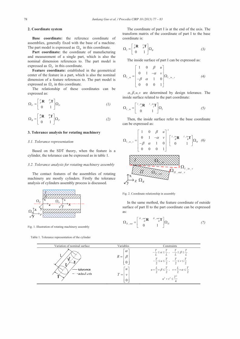
2. Coordinate system
Base coordinate: the reference coordinate of assemblies, generally fixed with the base of a machine. The part model is expressed as B in this coordinate.
Part coordinate: the coordinate of manufacturing and measurement of a single part, which is also the nominal dimension references to. The part model is expressed as P in this coordinate.
Feature coordinate: established in the geometrical center of the feature in a part, which is also the nominal dimension of a feature references to. The part model is expressed as F in this coordinate.
The relationship of these coordinates can be expressed as:
0 1
F FP P
F PR T
(1)
0 1
B BP P
B PR T
(2)
3. Tolerance analysis for rotating machinery
3.1. Tolerance representation
Based on the SDT theory, when the feature is a cylinder, the tolerance can be expressed as in table 1.
3.2. Tolerance analysis for rotating machinery assembly
The contact features of the assemblies of rotating machinery are mostly cylinders. Firstly the tolerance analysis of cylinders assembly process is discussed.
III
P
B
F
Fig. 1. Illustration of rotating machinery assembly
The coordinate of part I is at the end of the axis. The transform matrix of the coordinate of part I to the base coordinate is:
0 1
I IB B
I BR T
(3)
The inside surface of part I can be expressed as:
_ _ _
1 00 1
1 00 0 0 1
I in I in v
uv
(4)
, , ,u v are determined by design tolerance. The inside surface related to the part coordinate:
_ _
_ 0 1
I in I inI I
I in IR T
(5)
Then, the inside surface refer to the base coordinate can be expressed as:
1
_ _
_ _
1 00 1
1 0 0 10 0 0 1
I in I inB B
I in v B
uv R T (6)
I
II
_I in
_II out
_ _I in v_ _II out v
xy z B
Fig. 2. Coordinate relationship in assembly
In the same method, the feature coordinate of outside surface of part II to the part coordinate can be expressed as:
_ _
_ 0 1
II out II outII II
II out IIR T
(7)
Table 1. Tolerance representation of the cylinder
Variation of nominal surface Variables Constraints
0R
0
uT v
T TL L
T TL L
2 2T Tu
2 2T Tv
2 2L Tu
2 2L Tv
22 2
4Tu v
79 Junkang Guo et al. / Procedia CIRP 10 ( 2013 ) 77 – 83
According to the defined tolerance, the tolerance
matrix is:
_ _ _
1 00 1
1 00 0 0 1
II out II out v
uv
(8)
Then the relationship between the variation surface of part II and part II coordinate is:
1
_ _
_ _
1 00 1
1 0 0 10 0 0 1
II out II outII II
II out v II
uv R T (9)
Assuming that the variation surfaces of the inside surface of part I and outside surface of part II is superposition after assembly:
_ _ _ _I in v II out v (10)
The actual position of part II after assembly is:
0 1
II IIB B
II BR T
(11)
The tolerance analysis for cylinder feature of rotating machinery is discussed. Another important problem in rotating machinery assembly is the bearing assembly. In most of the rotating machinery, the main shaft is sustained by several bearings, so the assembly deviation transmit is in parallel.
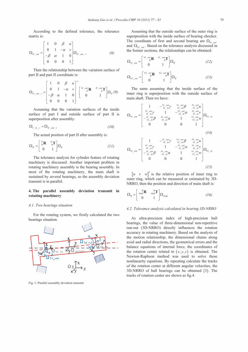
4. The parallel assembly deviation transmit in rotating machinery
4.1. Two bearings situation
For the rotating system, we firstly calculated the two bearings situation.
xy z
Fig. 3. Parallel assembly deviation transmit
Assuming that the outside surface of the outer ring is superposition with the inside surface of bearing chocker. The coordinate of first and second bearing are 1_b out and 2 _b out . Based on the tolerance analysis discussed in the former sections, the relationships can be obtained:
1_ 1_
1_ 0 1
b out b outB B
b out BR T
(12)
2 _ 2 _
2 _ 0 1
b out b outB B
b out BR T
(13)
The same assuming that the inside surface of the inner ring is superposition with the outside surface of main shaft. Then we have:
1_ 1_ 1_1_ 1_ 1_
1_ 1_ 1_1_ 1_ 1_
1_ 1_1_ 1_ 1_1_ 1_ 1_
11
10 0 0 1
b out b out b outb in b in b in
b out b out b outb in b in b in
b out b inb out b out b outb in b in b in
uvw
(14) 1_ 1_ 1_1_ 1_ 1_
1_ 1_ 1_1_ 1_ 1_
1_ 1_1_ 1_ 1_1_ 1_ 1_
11
10 0 0 1
b out b out b outb in b in b in
b out b out b outb in b in b in
b out b inb out b out b outb in b in b in
uvw
(15) Tu v w is the relative position of inner ring to
outer ring, which can be measured or estimated by 3D-NRRO, then the position and direction of main shaft is:
0 1
B Bshaft shaft
B shaftR T
(16)
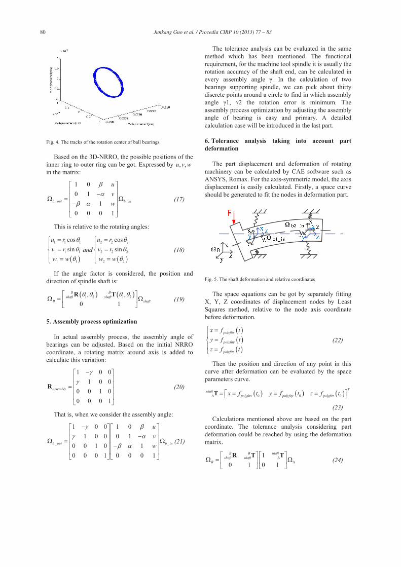
4.2. Tolerance analysis calculated in bearing 3D-NRRO
As ultra-precision index of high-precision ball bearings, the value of three-dimensional non-repetitive run-out (3D-NRRO) directly influences the rotation accuracy in rotating machinery. Based on the analysis of the motion relationship, the dimensional chains along axial and radial directions, the geometrical errors and the balance equations of internal force, the coordinates of the rotation center related to , ,x y z is obtained. The Newton-Raphson method was used to solve these nonlinearity equations. By repeating calculate the tracks of the rotation center at different angular velocities, the 3D-NRRO of ball bearings can be obtained [3]. The tracks of rotation center are shown as fig.4.
80 Junkang Guo et al. / Procedia CIRP 10 ( 2013 ) 77 – 83
Fig. 4. The tracks of the rotation center of ball bearings
Based on the 3D-NRRO, the possible positions of the inner ring to outer ring can be got. Expressed by , ,u v w in the matrix:
_ _
1 00 1
10 0 0 1
b out b in
uvw
(17)
This is relative to the rotating angles:
1 1 1
1 1 1
1 1
cossin
u rv rw w
and2 2 2
2 2 2
2 2
cossin
u rv rw w
(18)
If the angle factor is considered, the position and direction of spindle shaft is:
1 2 1 2, ,0 1
B Bshaft shaft
B shaftR T
(19)
5. Assembly process optimization
In actual assembly process, the assembly angle of bearings can be adjusted. Based on the initial NRRO coordinate, a rotating matrix around axis is added to calculate this variation:
1 0 01 0 0
0 0 1 00 0 0 1
assemblyR (20)
That is, when we consider the assembly angle:
_ _
1 0 0 1 01 0 0 0 1
0 0 1 0 10 0 0 1 0 0 0 1
b out b in
uvw
(21)
The tolerance analysis can be evaluated in the same method which has been mentioned. The functional requirement, for the machine tool spindle it is usually the rotation accuracy of the shaft end, can be calculated in every assembly angle . In the calculation of two bearings supporting spindle, we can pick about thirty discrete points around a circle to find in which assembly angle 1, 2 the rotation error is minimum. The assembly process optimization by adjusting the assembly angle of bearing is easy and primary. A detailed calculation case will be introduced in the last part.
6. Tolerance analysis taking into account part deformation
The part displacement and deformation of rotating machinery can be calculated by CAE software such as ANSYS, Romax. For the axis-symmetric model, the axis displacement is easily calculated. Firstly, a space curve should be generated to fit the nodes in deformation part.
Fig. 5. The shaft deformation and relative coordinates
The space equations can be got by separately fitting X, Y, Z coordinates of displacement nodes by Least Squares method, relative to the node axis coordinate before deformation.
polyfitx
polyfity
polyfitz
x f ty f tz f t
(22)
Then the position and direction of any point in this curve after deformation can be evaluated by the space parameters curve.
0 0 0
Tshaftpolyfitx polyfity polyfitzx f t y f t z f tT
(23)
Calculations mentioned above are based on the part coordinate. The tolerance analysis considering part deformation could be reached by using the deformation matrix.
10 1 0 1
B B shaftshaft shaft
BR T T
(24)
81 Junkang Guo et al. / Procedia CIRP 10 ( 2013 ) 77 – 83
7. Case study
The models and method mentioned above can be verified by taking a precision horizontal machining center for an example.
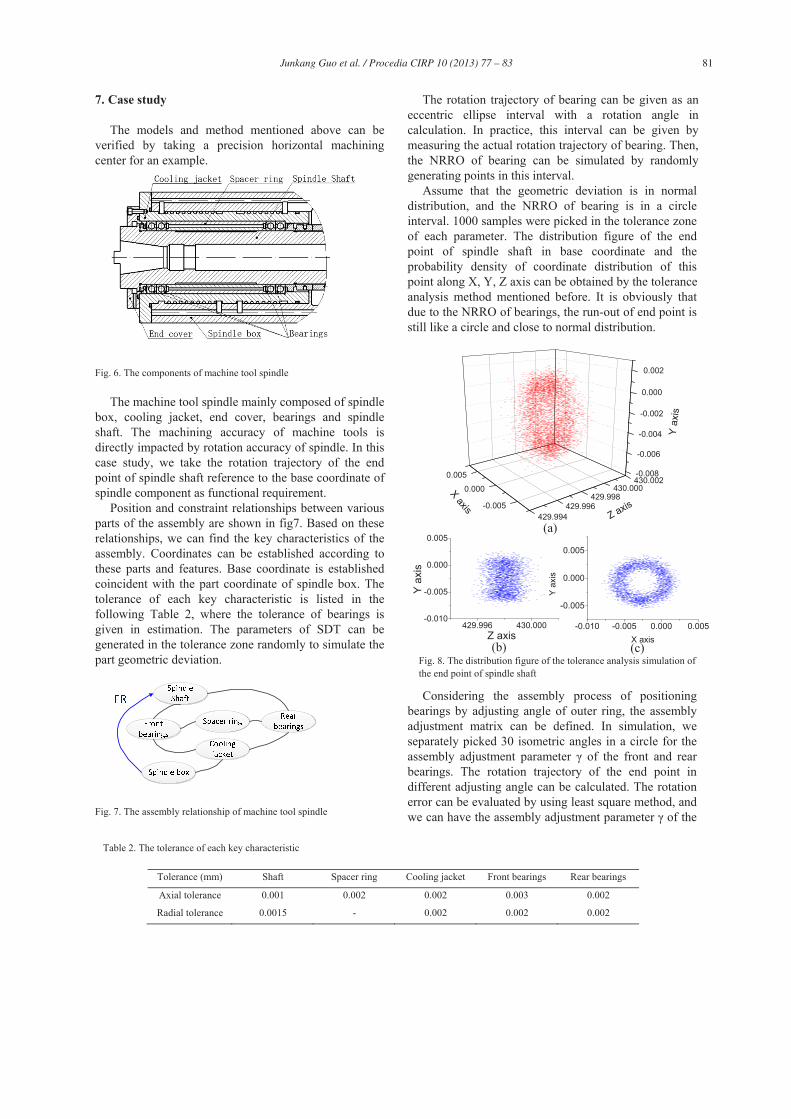
Fig. 6. The components of machine tool spindle
The machine tool spindle mainly composed of spindle box, cooling jacket, end cover, bearings and spindle shaft. The machining accuracy of machine tools is directly impacted by rotation accuracy of spindle. In this case study, we take the rotation trajectory of the end point of spindle shaft reference to the base coordinate of spindle component as functional requirement.
Position and constraint relationships between various parts of the assembly are shown in fig7. Based on these relationships, we can find the key characteristics of the assembly. Coordinates can be established according to these parts and features. Base coordinate is established coincident with the part coordinate of spindle box. The tolerance of each key characteristic is listed in the following Table 2, where the tolerance of bearings is given in estimation. The parameters of SDT can be generated in the tolerance zone randomly to simulate the part geometric deviation.
Fig. 7. The assembly relationship of machine tool spindle
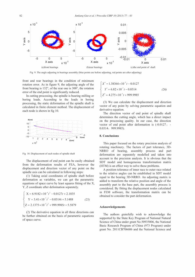
The rotation trajectory of bearing can be given as an eccentric ellipse interval with a rotation angle in calculation. In practice, this interval can be given by measuring the actual rotation trajectory of bearing. Then, the NRRO of bearing can be simulated by randomly generating points in this interval.
Assume that the geometric deviation is in normal distribution, and the NRRO of bearing is in a circle interval. 1000 samples were picked in the tolerance zone of each parameter. The distribution figure of the end point of spindle shaft in base coordinate and the probability density of coordinate distribution of this point along X, Y, Z axis can be obtained by the tolerance analysis method mentioned before. It is obviously that due to the NRRO of bearings, the run-out of end point is still like a circle and close to normal distribution.
Considering the assembly process of positioning bearings by adjusting angle of outer ring, the assembly adjustment matrix can be defined. In simulation, we separately picked 30 isometric angles in a circle for the assembly adjustment parameter of the front and rear bearings. The rotation trajectory of the end point in different adjusting angle can be calculated. The rotation error can be evaluated by using least square method, and we can have the assembly adjustment parameter of the
Table 2. The tolerance of each key characteristic
Tolerance (mm) Shaft Spacer ring Cooling jacket Front bearings Rear bearings
Axial tolerance 0.001 0.002 0.002 0.003 0.002
Radial tolerance 0.0015 - 0.002 0.002 0.002
Fig. 8. The distribution figure of the tolerance analysis simulation of the end point of spindle shaft
429.994429.996
429.998430.000
430.002
-0.005
0.000
0.005 -0.008
-0.006
-0.004
-0.002
0.000
0.002
X axis
Y ax
is
Z axis
-0.010 -0.005 0.000 0.005
-0.005
0.000
0.005Y
axis
X axis
429.996 430.000-0.010
-0.005
0.000
0.005
Y ax
is
Z axis
(a)
(b) (c)
82 Junkang Guo et al. / Procedia CIRP 10 ( 2013 ) 77 – 83
front and rear bearings in the condition of minimum rotation error. As in figure 9, the adjusting angle of the front bearing is 132°, of the rear one is 300°, the rotation error of the end point is significantly reduced.
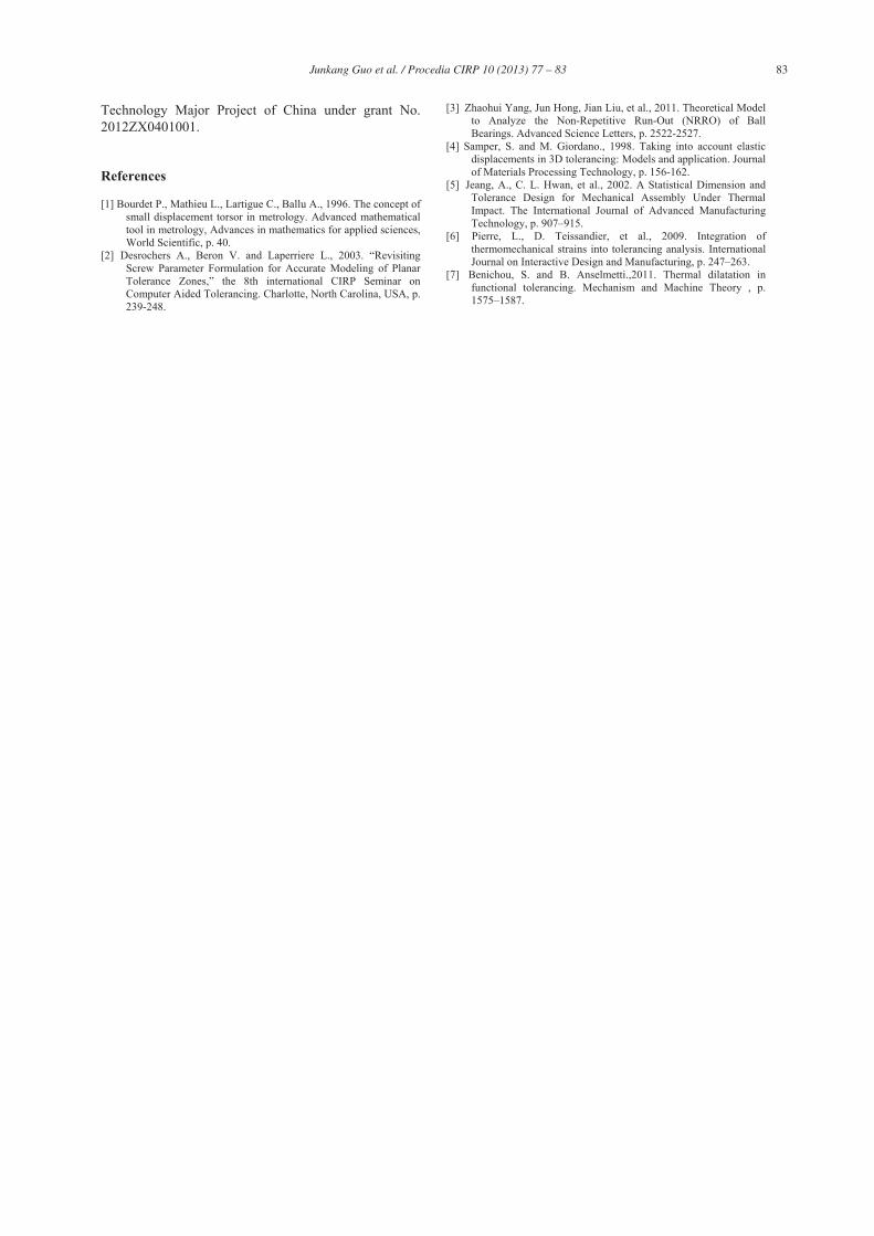
In cutting processing, the spindle is bearing milling or boring loads. According to the loads in boring processing, the static deformation of the spindle shaft is calculated in finite element method. The displacement of each node is shown in fig 10.
-5001 2 3 4 5 6 7 8
x 105
-10-505
10
Z(um)
Y(um)
X(um)
Fig 10. Displacement of each nodes of spindle shaft
The displacement of end point can be easily obtained from the deformation results of FEA, however the displacement and direction vector of any point on the spindle axis can be calculated in following steps:
(1) Taking axial coordinates of spindle shaft before deformation as variables, we can get the parametric equations of space curve by least squares fitting of the X, Y, Z coordinate after deformation separately.
6 2
7 2
5 2
X 6.9182 10 0.0127 2.1035
Y 3.41 10 0.0314t 5.1488
Z 2.1375 10 999.9985 5.5879
t t
t
t t
(25)
(2) The derivative equation in all three directions can be further obtained on the basis of parametric equations of space curve.
5
7
5
1.38364 10 0.0127
6.82 10 0.0314
4.275 10 999.9985
X t
Y t
Z t
(26)
(3) We can calculate the displacement and direction vector of any point by solving parametric equation and derivative equation.
The direction vector of end point of spindle shaft determines the cutting angle, which has a direct impact on the processing quality. In our case, the direction vector of end point after deformation is (-0.0127 -0.0314 999.9985).
8. Conclusions
This paper focused on the rotary precision analysis of rotating machinery. The factors of part tolerance, 3D-NRRO of bearing, assembly process and part deformation are separately modelled and taken into account to the precision analysis. It is obvious that the SDT model and homogeneous transformation matrix (HTM) is an effect way to solve these problems.
A position tolerance of inner race to outer race related to the relative angles can be established in SDT model equal to the bearing 3D-NRRO. An adjusting matrix is added to transform the relative position and angle of the assembly part to the base part, the assembly process is considered. By fitting the displacement nodes calculated in FEM software, the transformation matrix can be obtained to consider the part deformation.
Acknowledgements
The authors gratefully wish to acknowledge the supported by the State Key Program of National Natural Science of China under grant No.50935006, the National Basic Research Program of China (973 Program) under grant No. 2011CB706606 and the National Science and
-5 0 5x 10⁻³
-5
0
5
x 10-3
X axis
Y a
xis
-5 0 5x 10⁻³
-5
0
5
x 10-3
X axis
Y a
xis
-0.01 0 0.01-0.01
-0.005
0
0.005
0.01
X axis
Y a
xis
(a)front bearings (b)rear bearings (c)the end point of shaft
Fig 9. The angle adjusting in bearings assembly (blue points are before adjusting, red points are after adjusting)
83 Junkang Guo et al. / Procedia CIRP 10 ( 2013 ) 77 – 83
Technology Major Project of China under grant No. 2012ZX0401001.
References
[1] Bourdet P., Mathieu L., Lartigue C., Ballu A., 1996. The concept of small displacement torsor in metrology. Advanced mathematical tool in metrology, Advances in mathematics for applied sciences, World Scientific, p. 40.
[2] Desrochers A., Beron V. and Laperriere L., 2003. “Revisiting Screw Parameter Formulation for Accurate Modeling of Planar Tolerance Zones,” the 8th international CIRP Seminar on Computer Aided Tolerancing. Charlotte, North Carolina, USA, p. 239-248.
[3] Zhaohui Yang, Jun Hong, Jian Liu, et al., 2011. Theoretical Model to Analyze the Non-Repetitive Run-Out (NRRO) of Ball Bearings. Advanced Science Letters, p. 2522-2527.
[4] Samper, S. and M. Giordano., 1998. Taking into account elastic displacements in 3D tolerancing: Models and application. Journal of Materials Processing Technology, p. 156-162.
[5] Jeang, A., C. L. Hwan, et al., 2002. A Statistical Dimension and Tolerance Design for Mechanical Assembly Under Thermal Impact. The International Journal of Advanced Manufacturing Technology, p. 907–915.
[6] Pierre, L., D. Teissandier, et al., 2009. Integration of thermomechanical strains into tolerancing analysis. International Journal on Interactive Design and Manufacturing, p. 247–263.
[7] Benichou, S. and B. Anselmetti.,2011. Thermal dilatation in functional tolerancing. Mechanism and Machine Theory , p. 1575–1587.