IEEE standard for rotating electric machinery for rail and ... · IEEE Standard for Rotating...
39
The Institute of Electrical and Electronics Engineers, Inc. 3 Park Avenue, New York, NY 10016-5997, USA Copyright ' 2000 by the Institute of Electrical and Electronics Engineers, Inc. All rights reserved. Published 31 July 2000. Printed in the United States of America. Print: ISBN 0-7381-1922-9 SH94805 PDF: ISBN 0-7381-1923-7 SS94805 No part of this publication may be reproduced in any form, in an electronic retrieval system or otherwise, without the prior written permission of the publisher. IEEE Std 11-2000 (Revision of IEEE Std 11-1980) IEEE Standard for Rotating Electric Machinery for Rail and Road Vehicles Sponsor Electric Machinery Committee of the IEEE Power Engineering Society Approved 30 January 2000 IEEE-SA Standards Board Abstract: This standard applies to rotating electric machinery which forms part of the propulsion and major auxiliary equipment on internally and externally powered electrically propelled rail and road vehicles and similar large transport and haulage vehicles and their trailers where specified in the contract. Keywords: armature, electric input, electric output, impedance, load, phase control, propulsion, regeneration, shutdown, ventilation, waveforms, windage Authorized licensed use limited to: Eaton Corporation. Downloaded on November 06,2013 at 21:02:26 UTC from IEEE Xplore. Restrictions apply.
Transcript of IEEE standard for rotating electric machinery for rail and ... · IEEE Standard for Rotating...
The Institute of Electrical and Electronics Engineers, Inc.3 Park Avenue, New York, NY 10016-5997, USA
Copyright © 2000 by the Institute of Electrical and Electronics Engineers, Inc.All rights reserved. Published 31 July 2000. Printed in the United States of America.
Print: ISBN 0-7381-1922-9 SH94805PDF: ISBN 0-7381-1923-7 SS94805
No part of this publication may be reproduced in any form, in an electronic retrieval system or otherwise, without the prior written permission of the publisher.
IEEE Std 11-2000(Revision of IEEE Std 11-1980)
IEEE Standard for Rotating Electric Machinery for Rail and Road Vehicles
Sponsor
Electric Machinery Committeeof theIEEE Power Engineering Society
Approved 30 January 2000
IEEE-SA Standards Board
Abstract: This standard applies to rotating electric machinery which forms part of the propulsionand major auxiliary equipment on internally and externally powered electrically propelled rail androad vehicles and similar large transport and haulage vehicles and their trailers where specified inthe contract.Keywords: armature, electric input, electric output, impedance, load, phase control, propulsion,regeneration, shutdown, ventilation, waveforms, windage
Authorized licensed use limited to: Eaton Corporation. Downloaded on November 06,2013 at 21:02:26 UTC from IEEE Xplore. Restrictions apply.

IEEE Standards documents are developed within the IEEE Societies and the Standards Coordinating Com-mittees of the IEEE Standards Association (IEEE-SA) Standards Board. Members of the committees servevoluntarily and without compensation. They are not necessarily members of the Institute. The standardsdeveloped within IEEE represent a consensus of the broad expertise on the subject within the Institute aswell as those activities outside of IEEE that have expressed an interest in participating in the development ofthe standard.
Use of an IEEE Standard is wholly voluntary. The existence of an IEEE Standard does not imply that thereare no other ways to produce, test, measure, purchase, market, or provide other goods and services related tothe scope of the IEEE Standard. Furthermore, the viewpoint expressed at the time a standard is approved andissued is subject to change brought about through developments in the state of the art and commentsreceived from users of the standard. Every IEEE Standard is subjected to review at least every five years forrevision or reaffirmation. When a document is more than five years old and has not been reaffirmed, it is rea-sonable to conclude that its contents, although still of some value, do not wholly reflect the present state ofthe art. Users are cautioned to check to determine that they have the latest edition of any IEEE Standard.
Comments for revision of IEEE Standards are welcome from any interested party, regardless of membershipaffiliation with IEEE. Suggestions for changes in documents should be in the form of a proposed change oftext, together with appropriate supporting comments.
Interpretations: Occasionally questions may arise regarding the meaning of portions of standards as theyrelate to specific applications. When the need for interpretations is brought to the attention of IEEE, theInstitute will initiate action to prepare appropriate responses. Since IEEE Standards represent a consensus ofall concerned interests, it is important to ensure that any interpretation has also received the concurrence of abalance of interests. For this reason, IEEE and the members of its societies and Standards CoordinatingCommittees are not able to provide an instant response to interpretation requests except in those cases wherethe matter has previously received formal consideration.
Comments on standards and requests for interpretations should be addressed to:
Secretary, IEEE-SA Standards Board445 Hoes LaneP.O. Box 1331Piscataway, NJ 08855-1331USA
IEEE is the sole entity that may authorize the use of certification marks, trademarks, or other designations toindicate compliance with the materials set forth herein.
Authorization to photocopy portions of any individual standard for internal or personal use is granted by theInstitute of Electrical and Electronics Engineers, Inc., provided that the appropriate fee is paid to CopyrightClearance Center. To arrange for payment of licensing fee, please contact Copyright Clearance Center, Cus-tomer Service, 222 Rosewood Drive, Danvers, MA 01923 USA; (978) 750-8400. Permission to photocopyportions of any individual standard for educational classroom use can also be obtained through the Copy-right Clearance Center.
Note: Attention is called to the possibility that implementation of this standard mayrequire use of subject matter covered by patent rights. By publication of this standard,no position is taken with respect to the existence or validity of any patent rights inconnection therewith. The IEEE shall not be responsible for identifying patents forwhich a license may be required by an IEEE standard or for conducting inquiries intothe legal validity or scope of those patents that are brought to its attention.
Authorized licensed use limited to: Eaton Corporation. Downloaded on November 06,2013 at 21:02:26 UTC from IEEE Xplore. Restrictions apply.

Copyright © 2000 IEEE. All rights reserved. iii
Introduction
(This introduction is not part of IEEE Std 11-2000, IEEE Standard for Rotating Electric Machinery for Railand Road Vehicles.)
This standard provides for usual conditions. In addition, it provides for special conditions that have beenfound convenient or necessary at times in the industry, which may be invoked by agreement between themanufacturer and purchaser. The conditions chosen may affect the economics or performance, or both, ofmachines in a given situation.
Provisions where special agreement between manufacturer and purchaser may be invoked are as follows:
This standard parallels the major technical contents of International Electrotechnical Commission (IEC)Recommendation Publication 349, Rules for Rotating Electrical Machines for Rail and Road Vehicles. How-ever, it differs from IEC recommendation 349 in important respects.
These differences have been called to the attention of the U.S. Committee of Experts for IEC TechnicalCommittee 9, the International Mixed Committee on Electric Traction Equipment.
Subclause Provision1.3.2 High ambient temperature1.3.3 Special conditions of environment1.4.1 Type test quantities1.4.2 Routine overspeed and single phase or locked rotor test1.4.2.3 Routine commutation and characteristic test quantities,
quality control, and sampling plan1.5.6 Special conditions of electric input or output4.2.3 Greatest continuous rating5.2 Waiver of temperature-rise limits7.1 Dielectric test8.2.1 Commutation routine tests8.2.3 Level of visible sparking8.3.1 Interruption type tests9.3.1 Maximum design speed10.1.1 Routine test tolerances10.6.4.2 Assumed stray load loss10.6.5 Assumed harmonic losses10.7.4 Tolerance from contract curve10.8.1, 10.8.2, 10.8.3 Routine test tolerances11.2 Variation of performance with voltage11.3 Load reduction under condition of low supply voltage13.1 Commutator trueness measurement13.2 Vibration measurement13.3 Sound measurement13.4 Shaft voltage
Authorized licensed use limited to: Eaton Corporation. Downloaded on November 06,2013 at 21:02:26 UTC from IEEE Xplore. Restrictions apply.

iv Copyright © 2000 IEEE. All rights reserved.
This standard was prepared by a working group under the sponsorship of the DC, PM, and SpecialMachinery Subcommittee of the Electric Machinery Committee of the IEEE Power Engineering Society.The members of the working group were as follows:
Edward P. Priebe, Chair
The following members were technical advisors:
The following members of the balloting committee voted on this standard:
When the IEEE-SA Standards Board approved this standard on 30 January 2000, it had the followingmembership:
Richard J. Holleman, Chair
Donald N. Heirman, Vice Chair
Judith Gorman, Secretary
*Member Emeritus
Also included is the following nonvoting IEEE-SA Standards Board liaison:
Robert E. Hebner
Jennifer McClain LongmanIEEE Standards Project Editor
Karl W. BergerPaul R. Hokanson
Timothy A. KeckLloyd W. McSparranJohn T. Pesuit, Jr.
John J. Shea, Jr.Paul G. Vollmar
Ed Harbist Henry Liban Norman Vutz
J. C. AndreasMichael P. BaldwinKarl. W. BergerThomas H. BishopLinda Sue BoehmerPaul L. DandenoJames S. EdmondsBrian E. B. GottFranklin H. GroomsCharles A. GrossHoward B. Hamilton
Thomas J. HammonsPaul R. HokansonRichard A. Huber
James A. OliverEdward P. Priebe
Innocent KamwaTim KeckPeter H. LandrieuLloyd McSparranEdward J. MichaelsJ. R. MichalecThomas W. NehlJ. L. Oldenkamp
Charles M. RoweRichard SchiferlManoj R. ShahJohn SheaPatrick SmithKen StenroosPaul VollmarPaul Dieter WagnerEdward J. Woods
Satish K. AggarwalDennis BodsonMark D. BowmanJames T. CarloGary R. EngmannHarold E. EpsteinJay Forster*Ruben D. Garzon
James H. GurneyLowell G. JohnsonRobert J. KennellyE. G. Al KienerJoseph L. Koepfinger*L. Bruce McClungDaleep C. MohlaRobert F. Munzner
Louis-François PauRonald C. PetersenGerald H. PetersonJohn B. PoseyGary S. RobinsonAkio TojoHans E. WeinrichDonald W. Zipse
Authorized licensed use limited to: Eaton Corporation. Downloaded on November 06,2013 at 21:02:26 UTC from IEEE Xplore. Restrictions apply.

Copyright © 2000 IEEE. All rights reserved. v
Contents
1. Overview.............................................................................................................................................. 1
1.1 Scope............................................................................................................................................ 11.2 Purpose......................................................................................................................................... 11.3 Service conditions........................................................................................................................ 11.4 Test categories ............................................................................................................................. 21.5 Electric inputs or outputs ............................................................................................................. 2
2. References............................................................................................................................................ 3
3. Definitions ........................................................................................................................................... 3
4. Ratings and temperature-rise tests ....................................................................................................... 5
4.1 Classes of ratings ......................................................................................................................... 54.2 Continuous ratings and temperature-rise tests ............................................................................. 54.3 Initial temperature of machine for temperature-rise test to determine 1 h rating ........................ 54.4 Making of short-time overload test.............................................................................................. 54.5 Ventilation during temperature-rise test ...................................................................................... 64.6 Waveforms during temperature-rise tests .................................................................................... 64.7 Voltage during temperature-rise test............................................................................................ 64.8 Rated voltage ............................................................................................................................... 64.9 Contract ratings............................................................................................................................ 7
5. Temperature rises and temperature-rise tests....................................................................................... 7
5.1 Limits of temperature rise............................................................................................................ 75.2 Waiver of temperature-rise limit.................................................................................................. 95.3 Separability .................................................................................................................................. 95.4 Rotor cage windings .................................................................................................................... 9
6. Temperature measurements ................................................................................................................. 9
6.1 Measurement of the cooling-air temperature during tests ........................................................... 96.2 Method of measuring the temperature of parts .......................................................................... 106.3 Shutting down machine ............................................................................................................. 106.4 Rules for correcting to time of shutdown .................................................................................. 10
7. High-potential tests ............................................................................................................................ 11
7.1 Selection of test method............................................................................................................ 117.2 AC test procedure ..................................................................................................................... 117.3 DC test procedure ..................................................................................................................... 117.4 Test voltage............................................................................................................................... 117.5 Test voltage for machines operating on circuits with power ground........................................ 117.6 Test voltage for machines operating on ungrounded circuits ................................................... 127.7 Test voltage for machines operating on circuits with high-impedance,
ground-fault detection............................................................................................................... 127.8 New completed machines ......................................................................................................... 127.9 Repaired machines.................................................................................................................... 137.10 Machines in service condition .................................................................................................. 13
Authorized licensed use limited to: Eaton Corporation. Downloaded on November 06,2013 at 21:02:26 UTC from IEEE Xplore. Restrictions apply.

vi Copyright © 2000 IEEE. All rights reserved.
7.11 Connected apparatus ................................................................................................................. 13
8. Commutation tests (dc machines only).............................................................................................. 13
8.1 Commutation type tests ............................................................................................................. 138.2 Commutation routine tests ......................................................................................................... 158.3 Interruption type tests ................................................................................................................ 158.4 Evaluation of the degree of sparking ......................................................................................... 16
9. Overspeed requirements and test ....................................................................................................... 17
9.1 Overspeed test............................................................................................................................ 179.2 Results of overspeed test........................................................................................................... 179.3 Relation to vehicle speed ........................................................................................................... 17
10. Characteristic curves and tests ........................................................................................................... 17
10.1 Characteristic curves................................................................................................................. 1710.2 Methods for determining efficiency ......................................................................................... 1810.3 Losses to be considered for dc machines.................................................................................. 1910.4 Determination of losses in dc machines ................................................................................... 1910.5 Losses to be considered for inverter-driven induction motors ................................................. 2110.6 Determination of losses in inverter-driven induction motors ................................................... 2110.7 Declared curve type tests and tolerances .................................................................................. 2310.8 Routine characteristic tests and tolerances ............................................................................... 2410.9 Gear losses ................................................................................................................................ 24
11. External power systems ..................................................................................................................... 26
11.1 Supply voltage .......................................................................................................................... 2611.2 Propulsion performance voltage ............................................................................................... 2711.3 Supply characteristics ............................................................................................................... 2711.4 DC systems using regeneration................................................................................................. 27
12. Terminal marking .............................................................................................................................. 27
12.1 Traction motors......................................................................................................................... 2712.2 Rotating machines other than traction motors .......................................................................... 2812.3 Reactors .................................................................................................................................... 3012.4 Connection diagrams ................................................................................................................ 3012.5 Additional terminals ................................................................................................................. 30
13. Mechanical measurements ................................................................................................................. 30
13.1 Commutator trueness ................................................................................................................ 3013.2 Vibration ................................................................................................................................... 3113.3 Sound ........................................................................................................................................ 3113.4 Shaft voltage ............................................................................................................................. 32
Annex A (informative) Bibliography .......................................................................................................... 33
Authorized licensed use limited to: Eaton Corporation. Downloaded on November 06,2013 at 21:02:26 UTC from IEEE Xplore. Restrictions apply.

Copyright © 2000 IEEE. All rights reserved. 1
IEEE Standard for Rotating Electric Machinery for Rail and Road Vehicles
1. Overview
1.1 Scope
This standard applies to rotating electric machinery which forms part of the propulsion and major auxiliaryequipment on internally and externally powered electrically propelled rail and road vehicles and similarlarge transport and haulage vehicles and their trailers where specified in the contract.
Major auxiliary equipment includes equipment such as blower and compressor motors, motor-generator andmotor-alternator sets, auxiliary generators, and exciters, usually larger than 3 kW.
1.2 Purpose
The purpose of this standard is to define ratings, tests, and calculation procedures to permit comparisonamong machines for similar use, and to enable evaluation of the suitability of machines for a given use.
1.3 Service conditions
This standard applies under the following conditions:
1.3.1 Altitude
All temperature tests at the manufacturers plant shall be made at the sea-level rating. No correction in ratingis necessary when normal service altitude does not exceed 1200 m (4000 ft). A reduction in current rating of1% shall be made for each 300 m (1000 ft) additional elevation or fraction thereof.
1.3.2 Temperature
Whenever the temperature in the shade exceeds 40 °C, special stipulations may be agreed upon by themanufacturer and the purchaser.
Authorized licensed use limited to: Eaton Corporation. Downloaded on November 06,2013 at 21:02:26 UTC from IEEE Xplore. Restrictions apply.

IEEEStd 11-2000 IEEE STANDARD FOR ROTATING ELECTRIC MACHINERY
2 Copyright © 2000 IEEE. All rights reserved.
1.3.3 Special conditions
The manufacturer shall be informed by the purchaser of any particularly arduous condition such as dust,humidity, temperature, snow, dynamic effects, etc., under which the machines are intended to work.
1.4 Test categories
1.4.1 Type tests
Type tests to establish ratings and characteristics shall be carried out on all new products. The number oftype tests shall be one for every order for a new type, up to 100 machines on the order, and one for everyadditional 300 machines (or part thereof) for larger orders, unless otherwise agreed to between manufacturerand purchaser. Machines given type tests shall also be given routine tests.
1.4.2 Routine tests
Routine tests show that each machine is ready for service and like the type tested machines. Resistance,rotation, vibration, heating-up run, bearing temperature, and dielectric tests shall be carried out on allmachines. In no case do routine tests require precise temperature measurement.
For inverter-driven induction motors, no-load phase balance and magnetizing current and kilowatt inputtests shall be run, and overspeed and single phase tests may be run by agreement.
For synchronous machines, overspeed test shall be run on each machine.
For dc machines, overspeed test shall be run on each machine, and requirements for commutation and char-acteristic tests shall be met by one of the methods given below.
1.4.2.1
Load test may be used to demonstrate commutation and characteristics directly.
1.4.2.2
Simulated load test may be used to demonstrate that the factors that affect commutation and characteristicsagree with identical tests on machines that have had type test.
1.4.2.3
On machines produced in large quantity and assembled by precision methods, statistical methods may beused to determine the number of machines subject to commutation and characteristic tests. The qualitycontrol and sampling plan may be subject to agreement between manufacturer and purchaser.
1.5 Electric inputs or outputs
1.5.1
DC motors supplied from rectified polyphase alternating current with not less than six-pulse rectificationwithout phase control are considered to be operating on smooth current. No correction is needed from testsrun on smooth current.
Authorized licensed use limited to: Eaton Corporation. Downloaded on November 06,2013 at 21:02:26 UTC from IEEE Xplore. Restrictions apply.

IEEEFOR RAIL AND ROAD VEHICLES Std 11-2000
Copyright © 2000 IEEE. All rights reserved. 3
1.5.2
DC motors supplied from rectified single-phase alternating current or from pulse-control devices are consid-ered to be operating on undulating current. Type tests for temperature rise, commutation, characteristics, andefficiency shall be made with undulating current with pulsation frequency and ripple as in service. Tests withsmooth current may also be run.
1.5.3
AC machines that operate with essentially sinusoidal waveform should be tested under those conditions.
1.5.4
AC machines producing or fed with nonsinusoidal waveform should have type tests with waveforms as inservice. Tests with sinusoidal waveform may also be run.
1.5.5
The effects of load characteristics and supply characteristics (11.3 and 11.4) shall be taken into account inspecifying electric inputs or outputs of machines, particularly ac auxiliaries.
1.5.6
Special conditions of electric input or output are subject to agreement between manufacturer and purchaser.
2. References
This standard shall be used in conjunction with the following publications. When a standard is supersededby an approved revision, the revision shall apply.
ANSI/NEMA CB 11995, Brushes for Electrical Machines.1
IEEE Std 11986 (Reaff 1992), IEEE Standard General Principles for Temperature Limits in the Rating ofElectric Equipment and for the Evaluation of Electrical Insulation.2
IEEE Std 1121996, IEEE Standard Test Procedure for Polyphase Induction Motors and Generators.
3. Definitions
3.1 alternator: An ac generator.
3.2 as built curve: A curve that is found on an individual machine during testing. Syn: manufacturedcurve.
3.3 average voltage: The value declared by the user to be the average of the system described, whereexternally powered.
1NEMA publications are available from Global Engineering Documents, 15 Inverness Way East, Englewood, Colorado 80112, USA(http://global.ihs.com/).2IEEE publications are available from the Institute of Electrical and Electronics Engineers, 445 Hoes Lane, P.O. Box 1331, Piscataway,NJ 08855-1331, USA (http://standards.ieee.org/).
Authorized licensed use limited to: Eaton Corporation. Downloaded on November 06,2013 at 21:02:26 UTC from IEEE Xplore. Restrictions apply.

IEEEStd 11-2000 IEEE STANDARD FOR ROTATING ELECTRIC MACHINERY
4 Copyright © 2000 IEEE. All rights reserved.
3.4 continuous rating: The output that the machine can sustain for an unlimited period under the conditionsof Clause 4 without exceeding the limits of temperature rise of Clause 5.
3.5 contract curve: A specified machine characteristic curve that becomes part of the contract.
3.6 current ripple: Current ripple, for the purpose of this standard, is defined as expressed in percent, where Imax and Imin are the maximum and minimum
values of the current waveform, provided that the current is continuous.
3.7 declared curve: A characteristic curve of the machine type, as obtained by averaging the results oftesting four to ten machines, of which at least two shall have had a type test.
3.8 electric thermometer: An instrument that utilizes electric means to measure temperatureIEEE Std 100-1996). Electric thermometers include thermocouples and resistance temperature detectors.
3.9 heating-up run: A period of operation with current and ventilation designed to bring the machine toapproximately its temperature-rise limit.
3.10 manufacturer: The organization supplying the electric machinery to the purchaser. For the purpose ofthis standard it may include a repair contractor.
3.11 nominal system voltage: A number used to denote the general level of voltage of the system describedand, in the case of an externally powered system, selected from the list of preferred values in Clause 11.
3.12 one hour rating: The output that the machine can sustain for 1 h starting cold under the conditions ofClause 4 without exceeding the limits of temperature rise of Clause 5.
3.13 purchaser: The organization placing the contract for the machinery or its repair; often called theuser.
3.14 pulse control: Means by which the voltage applied to a machine circuit departs from being essentiallyconstant if unidirectional, or from being essentially sinusoidal if alternating. Pulse control devices include,but are not limited to, choppers, inverters, and rectifiers.
3.15 rated voltage: The voltage specified at the terminals of a machine.
3.16 rating: The output at the shaft if a motor, or at the terminals if a generator, assigned to a machine underspecified conditions of speed, voltage, temperature rise, etc.
3.17 routine test: A test showing that each machine has been run and found to be sound electrically andmechanically, and is essentially identical with those that have been type tested.
3.18 short-time overload rating: The output that the machine can sustain for a specified time starting hotunder the conditions of Clause 4, without exceeding the limits of temperature rise of Clause 5.
3.19 smooth current: Current that remains unidirectional and the ripple of which does not exceed 3%.
3.20 type test: A test made by the manufacturer on a machine that is identical in all essential respects withthose supplied on an order, to demonstrate that it complies with this standard.
3.21 undulating current: Current that remains unidirectional, but the ripple of which exceeds that definedfor smooth current.
Imax Imin ) Imax Imin+( )⁄+[ ] 100×
Authorized licensed use limited to: Eaton Corporation. Downloaded on November 06,2013 at 21:02:26 UTC from IEEE Xplore. Restrictions apply.

IEEEFOR RAIL AND ROAD VEHICLES Std 11-2000
Copyright © 2000 IEEE. All rights reserved. 5
4. Ratings and temperature-rise tests
4.1 Classes of ratings
This standard recognizes three classes of ratings: continuous rating, 1 h rating, and short time overloadrating.
4.2 Continuous ratings and temperature-rise tests
4.2.1
The continuous rating of a machine applied in duty that is long compared to the thermal time constant of themachine generally will be the point of greatest continuous tractive effort with the highest continuous fluxlevel. The test shall be performed with inputs as in service unless 4.6.1 applies. It shall be ascertained that noother point is limiting.
4.2.2
The continuous rating of a machine applied in duty that has short cycles compared to the thermal timeconstant of the machine will be the steady rating that produces the same heating with the same ventilation inthe same time as the duty cycle. This continuous rating is calculated from speed, time, distance, rms current,etc., over the duty cycle. Ripple in dc or harmonics in ac change during the duty cycle so it may not bepossible to provide the continuous rating point with waveforms as in service. Subclause 4.6.1 may apply.
A duty cycle test shall be performed with the pulse control to be used in service to demonstrate that thetemperature rises are comparable to those at the calculated continuous rating. The machine shall be operatedin simulation of the actual duty cycle, including dwell time, as realistically as possible. The cycle shall berepeated until temperature rises have leveled. The test shall end at a temperature rise peak, if appreciable.
4.2.3
Where agreed, a machine may be tested to find the greatest continuous rating that will meet temperature riselimits with assurance. Such a rating must be used with care that other conditions have not changed to renderthe rating inapplicable.
4.2.4
A continuous temperature test shall be continued until the temperature rises that can be observed during thetest have attained steady final values. See Table 1 in 5.1. In order to abridge the long time required to attainsteady temperatures, reasonable overload or reduction of ventilation during the preliminary heating period ispermissible.
4.3 Initial temperature of machine for temperature-rise test to determine 1 h rating
The temperature-rise test to determine the 1 h rating shall commence only when the windings and other partsof the machine are within 4 °C of the cooling-air temperature at the time of starting the test.
4.4 Making of short-time overload test
The short-time overload capacity of the machine shall be determined by one or more temperature-rise testsfollowing the continuous rating test at the highest continuous current. The cooling curve of the earlier rating
Authorized licensed use limited to: Eaton Corporation. Downloaded on November 06,2013 at 21:02:26 UTC from IEEE Xplore. Restrictions apply.

IEEEStd 11-2000 IEEE STANDARD FOR ROTATING ELECTRIC MACHINERY
6 Copyright © 2000 IEEE. All rights reserved.
test shall be plotted as taken, and the overload shall be applied when the extrapolation of this curve indicatesthat the proper initial armature temperature rise has been reached. The overload shall then be applied undernormal ventilation conditions and at the voltage that corresponds to the test current on the machinecharacteristic and shall be maintained constant for a period estimated to reach the final temperature risegiven in Table 2 in 5.1. The short-time overload rating of the machine may be calculated from a test thatdoes not differ in final temperature rise from that in Table 2 by more than ±10 °C.
4.5 Ventilation during temperature-rise test
The test shall be carried out with the machine arranged as in service, with all those parts that would affect thetemperature rise of the machine in place, but without any ventilation corresponding to that produced by themotion of the vehicle itself.
4.6 Waveforms during temperature-rise tests
4.6.1
Smooth current or sine wave power may be used rather than pulse-controlled if the ripple or harmoniccontent would be so low that the added losses may be neglected or accounted for.
4.6.2
Rating test(s) shall be repeated with smooth current or sine wave supply to establish reference for furthertype tests. If type test equipment can not reach the rating point, another point at the same flux level may haveto be used.
4.6.3
Heat run(s) on waveforms as in service are required on one machine deemed typical. Other type tests arecompared to the reference test(s).
4.7 Voltage during temperature-rise test
The voltage applied to a machine during the temperature-rise test shall be the rated voltage as defined in 4.8.
4.8 Rated voltage
4.8.1 Motors on externally powered vehicles
The rated voltage of a motor is the same as the nominal supply voltage of the traction network (see Table 4,Clause 11) in all cases where the motor is fed directly from the line.
4.8.2 Motors in series
For motors connected permanently in series the rated voltage of the motor is designated by the ratio E/n, Ebeing the nominal supply voltage and n the number of motors in series.
4.8.3 Motors on internally powered vehicles
The rated voltage of a traction motor fed from a generator carried on the vehicle shall be at least equal to itsshare of the generator output voltage at the continuous rating of the motor.
Authorized licensed use limited to: Eaton Corporation. Downloaded on November 06,2013 at 21:02:26 UTC from IEEE Xplore. Restrictions apply.
IEEEFOR RAIL AND ROAD VEHICLES Std 11-2000
Copyright © 2000 IEEE. All rights reserved. 7
4.8.4 Traction generator or alternator
A traction generator or alternator which is part of a motor-generator set carried on the vehicle or is drivenfrom a prime mover on the vehicle usually will have a variable-voltage, variable-current characteristic. Highvoltage is of interest since it will stress the commutator, or rectifiers in the case of an alternator where therectifiers form an integral part of the generator, and since the exciting field windings are operated at highcurrent. High current is of interest from the standpoint of heating of the armature and other windings andrectifiers which carry main current. Such a generator or alternator has two continuous ratings on itscharacteristic curve which are as follows:
4.8.4.1
The continuous current rating of a generator or alternator is the continuous rating that corresponds to thehigher output current. The continuous current rating for an alternator with rectifiers is the value of therectified dc at the output of the rectifiers.
4.8.4.2
The continuous voltage rating is the continuous rating that corresponds to the higher output voltage.
4.8.5 Exciting supply
The rated voltage of the exciting supply shall be sufficient to provide this continuous voltage rating of themain generator.
4.8.6 Regulated supply
The rated voltage of a machine generating electricity under the control of a regulator or of a machine fedfrom such a generator shall be the nominal value of the regulated voltage.
4.8.7 Fixed excitation
The rated voltage of a machine on a car or locomotive generating electricity under a fixed value of excitationshall be that occurring at the rated speed and current of the machine.
4.8.8 Pulse control
The rated voltage of a motor fed by pulse control shall be the average value (if unidirectional current) or theeffective value of the fundamental frequency component (if alternating current) of the motor voltage overthe recurring waveform with the motor delivering rated output.
4.9 Contract ratings
Each rating specified in the contract is to be confirmed by test.
5. Temperature rises and temperature-rise tests
5.1 Limits of temperature rise
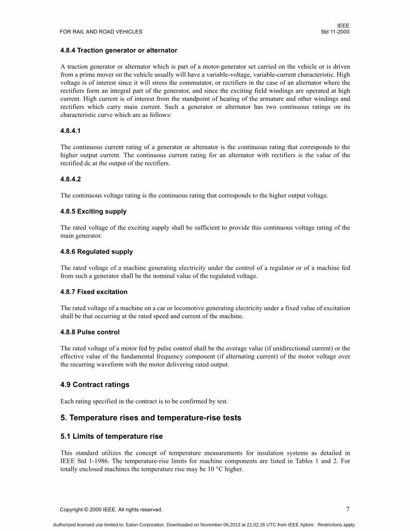
This standard utilizes the concept of temperature measurements for insulation systems as detailed inIEEE Std 1-1986. The temperature-rise limits for machine components are listed in Tables 1 and 2. Fortotally enclosed machines the temperature rise may be 10 °C higher.
Authorized licensed use limited to: Eaton Corporation. Downloaded on November 06,2013 at 21:02:26 UTC from IEEE Xplore. Restrictions apply.

IEEEStd 11-2000 IEEE STANDARD FOR ROTATING ELECTRIC MACHINERY
8 Copyright © 2000 IEEE. All rights reserved.
Table 1Observable 1 h or continuous temperature rise
Temperature-rise class designation Component or winding Method of temperature
measurementTemperature
rise (°C)B Rotating armature winding Resistance 120
Stationary armature winding Resistance 120Embedded detector 130
Stationary field winding Resistance 130Rotating field winding Resistance 120Commutator and/or collector Electric thermometer 120
F Rotating armature winding Resistance 140Stationary armature winding Resistance 140
Embedded detector 155Stationary field winding Resistance 155Rotating field winding Resistance 140Commutator and/or collector Electric thermometer 120
H Rotating armature winding Resistance 160Stationary armature winding Resistance 160
Embedded detector 180Stationary field winding Resistance 180Rotating field winding Resistance 160Commutator and/or collector Electric thermometer 120
C Rotating armature winding Resistance 180Stationary armature winding Resistance 180
Embedded detector 200Stationary field winding Resistance 200Rotating field winding Resistance 180Commutator and/or collector Electric thermometer 120
NOTENo correction shall be made for cooling-air temperature during test bewteen the limits of 10 °C and 40 °C.
Table 2Overload test, starting hot observable short-time temperature rise
Temperature-riseclass designation
Rise by resistance (°C)
Initial Final
B 75 135
F 85 155
H 100 180
C 120 220NOTEAlthough armature windings are generally limiting, the overload shall not result ininjurious temperatures in any other parts of the machine.
Authorized licensed use limited to: Eaton Corporation. Downloaded on November 06,2013 at 21:02:26 UTC from IEEE Xplore. Restrictions apply.

IEEEFOR RAIL AND ROAD VEHICLES Std 11-2000
Copyright © 2000 IEEE. All rights reserved. 9
5.2 Waiver of temperature-rise limits
When agreed to by manufacturer and purchaser, the temperature limits listed may be altered or madeoptional.
5.3 Separability
If the manufacturer so desires, different parts of the same machine may have different classes of insulation,and each may be rated for its corresponding temperature rise.
5.4 Rotor cage windings
Temperatures of rotor cages and end rings shall not cause injury to themselves or other parts.
6. Temperature measurements
6.1 Measurement of the cooling-air temperature during tests
6.1.1 Placing of thermometers
6.1.1.1 Totally enclosed machines
The cooling-air temperature shall be measured by means of several thermometers placed at different pointsaround and halfway up the machines at a distance of 1 m to 2 m (3 ft to 6 ft) and protected from drafts andabnormal heat radiation as specified in 6.1.2.
6.1.1.2 Self-ventilated machines (except those equipped with inlet ducts)
The cooling-air temperature shall be measured by thermometers placed as close as possible to each intakeopening, but protected from radiated or conducted heat in such a way as to measure the actual temperature ofthe air entering the machine.
6.1.1.3 Ventilated machines equipped with inlet pipes or ducts
For determining the temperature rises of the enclosed parts when the cooling air is supplied through ducts orpipes, the temperature of the cooling air shall be measured in the test machine inlet duct system at a distancenot less than 1 m (3 ft) from the machine itself.
6.1.2 Use of oil cup
In order to avoid errors due to the time lag between the temperature of large machines and the variation inthe cooling-air temperature, all reasonable precautions shall be taken to reduce these variations and theerrors arising therefrom. Thus the thermometer for determining the cooling-air temperature should beimmersed in a suitable liquid, such as oil, in a suitably heavy metal cup when the cooling-air temperature issubject to such variations that an error in the temperature rise might result.
A convenient form for such an oil cup consists of a metal cylinder with a hole drilled partly through it. Thishole is filled with oil, and the thermometer is placed therein with its bulb well immersed. The response of thethermometer to various rates of temperature change will depend largely upon the size, kind of material, andmass of the containing cup and may be further regulated by adjusting the amount of oil in the cup. The largerthe machine under test, the larger should be the metal cylinder employed as an oil cup in the determination
Authorized licensed use limited to: Eaton Corporation. Downloaded on November 06,2013 at 21:02:26 UTC from IEEE Xplore. Restrictions apply.

IEEEStd 11-2000 IEEE STANDARD FOR ROTATING ELECTRIC MACHINERY
10 Copyright © 2000 IEEE. All rights reserved.
of the cooling-air temperature. The smallest size of oil cup employed in any case shall consist of a metalcylinder 25 mm (1 in) in diameter and 50 mm (2 in) high.
6.1.3 Mean temperature
The value to be adopted for the cooling-air temperature during a test is the mean of the readings of thethermometers (placed as in 6.1.1) taken at equal intervals of time during the last quarter of the duration ofthe test.
6.2 Method of measuring the temperature of parts
Two methods of determining temperatures of respective parts are recognized, 1) for commutators orcollectors, by electric thermometer, and 2) for windings, by resistance or embedded detector.
6.2.1 Electric-thermometer method
In this method the temperature is determined by means of electric thermometers, applied immediately afterthe machine has stopped, on the accessible parts of the commutator, collector, or end rings at the spotspresumed to be the hottest.
6.2.2 Resistance method
In this method the temperature rise of the windings is determined by their increased resistance as measuredby a Kelvin double bridge or equivalent method.
Determination of the Mean Temperature Rise of a Copper Winding by Variation of its Electrical Resistance. Forcopper windings the temperature rise at the end of the test is determined by the following formula:
where
ta is mean cooling-air temperature as defined in 6.1.1 during the last quarter of the duration of the testt2 is temperature of the winding at the end of the test, °Ct1 is temperature of the winding when cold at the moment of the initial resistance measurement, °CR2 is resistance of the winding at the end of the test, ohmR1 is initial resistance of the winding when cold, ohm
6.3 Shutting down machine
Separate ventilation shall cease at the instant power is cut off from the machine being tested. This is theinstant of shutdown. Means shall be used to limit the stopping period to a value not exceeding 1 min formachines rated up to and including 100 kW continuous rating and 2 min for machines rated above 100 kWcontinuous rating.
6.4 Rules for correcting to time of shutdown
A series of resistance measurements shall be taken beginning within 45 s after shutdown, continued for aminimum of 5 min, and plotted in terms of time intervals after shutdown. The use of semilog paper with timeon the linear axis is suggested. A curve shall be drawn through these points and extrapolated back to the
t2 ta t1R2 R1
R1------------------ 234.5 t1+( ) ta+=
Authorized licensed use limited to: Eaton Corporation. Downloaded on November 06,2013 at 21:02:26 UTC from IEEE Xplore. Restrictions apply.

IEEEFOR RAIL AND ROAD VEHICLES Std 11-2000
Copyright © 2000 IEEE. All rights reserved. 11
instant of shutdown. The temperature so derived shall be taken as the temperature at the instant of shutdown.The temperature of stationary windings operating on smooth dc may be measured by the volt-ampereresistance method just prior to shutdown. In the case of the short-time overload test these readings shall betaken not more than 10 s before shutdown.
7. High-potential tests
7.1 Selection of test method
The nature of dielectric stresses due to ac and dc high-potential tests differs for numerically equal testvoltages. Alternating high-potential tests shall be used after completion of new machines, unless otherwiseagreed to between manufacturer and purchaser. The ac test is a proof test, and failure to pass will causedamage. The direct high-potential test is a diagnostic test which may be terminated if leakage currentindicates impending failure. The dc test is recommended for use on machines in service condition. The dctest may be used with or in place of the ac test by agreement between manufacturer and purchaser.
7.2 AC test procedure
The test voltage shall be as nearly as possible of the sine-wave form, at utility frequency. The effective valueof the wave shall be the test voltage. The test shall begin at a voltage of less than one third the test voltageand shall be increased gradually to the full test voltage. The full test voltage shall be maintained for 60 s andthen gradually reduced.
7.3 DC test procedure
Beginning from zero, the voltage shall be applied in increments of approximately 20% of final voltage,allowing time at each increment for leakage current to stabilize. Leakage current shall be observed carefullyfor sharp rising fluctuations which indicate impending breakdown of insulation. The final full test voltageshall be maintained for 60 s. The purchaser may require a record of the leakage current for each machine.After application of a high direct potential, the grounding of windings is important for safety as well as forthe accuracy of subsequent tests. The grounding time should be a minimum of four times the charge time.
7.4 Test voltage
The test voltage is based on the operating voltage, according to the applicable provision below. The voltageE is taken as the root-mean-square value if the supply voltage is alternating, or as the average value foroperation with undulating current. The test voltage given is for ac tests; for dc tests the test voltage shall bemultiplied by 1.75. In measuring the voltage with a voltmeter, the instrument should derive its voltage fromthe high-voltage circuit either directly or through an auxiliary ratio transformer, or by means of a voltmetercoil placed in the testing transformer.
7.5 Test voltage for machines operating on circuits with power ground
The test voltage for machines operating on circuits with power ground shall be at least 2E plus 1500 (exceptwith a minimum of 2500 V on the main traction machines), where E equals:
7.5.1 External line
The nominal system voltage where motors are connected directly to the line or fed from pulse-controlapparatus, or the highest motor voltage to ground if greater than line voltage.
Authorized licensed use limited to: Eaton Corporation. Downloaded on November 06,2013 at 21:02:26 UTC from IEEE Xplore. Restrictions apply.

IEEEStd 11-2000 IEEE STANDARD FOR ROTATING ELECTRIC MACHINERY
12 Copyright © 2000 IEEE. All rights reserved.
7.5.2 External line through transformer
The highest voltage from transformer traction windings to ground with nominal system voltage on theprimary, where motors are connected to a transformer directly or through pulse-control apparatus.
7.5.3 Internal power
The highest machine voltage to ground in operation.
7.6 Test voltage for machines operating on ungrounded circuits
The test voltage for machines operating on ungrounded circuits shall be at least 2E plus 1000 (except with aminimum of 2000 V on main traction machines), where E equals:
7.6.1 External line through transformer
The highest voltage applied to one or more permanently interconnected motors with nominal system voltageon the primary, where motors are connected to a transformer directly or through pulse-control apparatus.
7.6.2 Internal power
The highest voltage of the source in operation.
7.7 Test voltage for machines operating on circuits with high-impedance ground-fault detection
High-impedance ground-fault detection here means a connection that establishes ground potential andprovides for the detection of ground current at a value too low to cause serious damage. The test voltage formachines operating on circuits with high-impedance ground shall be at least 2E plus 1000 (except with aminimum of 2000 V on main traction machines), where E equals:
7.7.1 External line through transformer
The highest voltage to ground at the machine terminals with nominal system voltage on the primary, wheremotors are connected to a transformer directly or through pulse-control apparatus.
7.7.2 Internal power
The highest machine voltage to ground in operation.
7.8 New completed machines
High-potential tests are routine tests which shall be carried out on each machine in the manufacturers plant.The test shall be made while the machine is hot after the heating-up run, and overspeed test, if required. Thetest voltage specified above shall be applied in turn between each winding and the frame The windings notbeing tested shall be connected to the frame as ground. For dc tests the leakage current shall not exceed10 microA after 60 s at the full test voltage.
Authorized licensed use limited to: Eaton Corporation. Downloaded on November 06,2013 at 21:02:26 UTC from IEEE Xplore. Restrictions apply.

IEEEFOR RAIL AND ROAD VEHICLES Std 11-2000
Copyright © 2000 IEEE. All rights reserved. 13
7.9 Repaired machines
Completely rewound and treated machines shall be tested in the same manner as newly completed machines.If a rotor is tested separately, the shaft shall be used as ground.
7.10 Machines in service condition
7.10.1 DC high-potential test
DC high-potential tests may be used to evaluate the machine condition. The test voltage should be 80% ofthat required if the machine were new; the recommended limit on leakage current is 1 mA.
7.10.2 AC high-potential test
High-potential tests should be preceded by a dc insulation resistance test. The insulation resistance testvoltage should be 500 V on machines that would have alternating high-potential tests of less than 2000 Vwhen new, and up to 1000 V for other machines. Alternating high-potential tests should not be carried out ona machine having less than 2 MΩ insulation resistance. If a high-potential test is made, the test voltageshould be half that required if the machine were new.
7.11 Connected apparatus
When units of apparatus are electrically connected and tested as an electrical system, the system shall betested at 85% of the lowest required test voltage of any of the individual units of apparatus.
8. Commutation tests (dc machines only)
8.1 Commutation type tests
8.1.1
Commutation type tests shall be carried out in the manufacturers plant, with care being taken to avoidexceeding normal operating temperatures or speeds.
8.1.2
In general, commutation type tests shall be carried out at various points over the entire operating range of themachine, in both directions of rotation if the machine normally operates in both directions.
8.1.3
Commutation type tests on regulated machines shall be carried out at various operating points within the fullrange of operation of the regulator.
8.1.4
Commutation type tests shall be carried out on motors fed directly or through a transformer from the line atvarious values of current and corresponding field strength shown on the motoring characteristic curve and ata voltage corresponding to the maximum voltage given in Clause 11, Tables 4 and 5.
Authorized licensed use limited to: Eaton Corporation. Downloaded on November 06,2013 at 21:02:26 UTC from IEEE Xplore. Restrictions apply.

IEEEStd 11-2000 IEEE STANDARD FOR ROTATING ELECTRIC MACHINERY
14 Copyright © 2000 IEEE. All rights reserved.
8.1.5
For motors which operate regeneratively, commutation type tests shall be carried out at various values ofcurrent and speed shown on the regenerative characteristic curve, the machine running as a generator at avoltage corresponding to the maximum voltage given in Clause 11, Tables 4 and 5.
8.1.6
For motors which operate with rheostatic braking, commutation type tests shall be carried out at variousvalues of current, field strength, and corresponding speed shown on the rheostatic braking characteristiccurves.
8.1.7
Where motors are connected permanently in series without mechanical coupling, the motor shall in additionbe type tested as a motor at a current corresponding to 75% of the current at the continuous rating and at avoltage of 1.5 times the rated voltage of the motor and with the fields connected for full excitation.
8.1.8
For traction motors fed from a generator carried on the vehicle, type tests shall be carried out at variousvalues of voltage per motor and current per motor corresponding to points on the generator characteristiccurves.
8.1.9
Where the motor is arranged for field control, it shall be run at various field strengths at which it may becalled upon to operate in service.
8.1.10
Where motors fed from a generator carried on the vehicle are connected permanently in series withoutmechanical coupling, the motor shall in addition be type tested with maximum field strength at 1.5 times thevoltage per motor, corresponding to the maximum voltage shown on the maximum generator characteristiccurve with the current adjusted so that the motor runs at maximum design speed.
8.1.11
Where pulse control is used, the motor shall be tested under the applicable conditions given above, withripple frequency and waveform as in service.
8.1.12
Where machines operate on other than smooth current, tests shall be carried out with waveforms as inservice. Additional tests may be carried out on smooth dc to provide correlation for routine tests.
8.1.13
The machine shall withstand each of the commutation tests without mechanical deterioration, flashing orpermanent damage; permanent damage being that which would prevent successful operation of the machineafter completion of the tests. The presence of some visible sparking is not necessarily evidence ofunsatisfactory commutation.
Authorized licensed use limited to: Eaton Corporation. Downloaded on November 06,2013 at 21:02:26 UTC from IEEE Xplore. Restrictions apply.

IEEEFOR RAIL AND ROAD VEHICLES Std 11-2000
Copyright © 2000 IEEE. All rights reserved. 15
8.2 Commutation routine tests
8.2.1
On machines given commutation routine tests, commutation shall be observed under conditions agreed uponbetween manufacturer and purchaser, generally at not more than six points per machine which type testshave shown to be significant. One of these points shall be after the overspeed test.
8.2.2
On machines produced in quantity where precision methods are used to assure proper commutating pole fluxin the assembled machine, the fitting of brushes and the observation of commutation may be omitted.
8.2.3
The machine shall withstand each commutation routine test without mechanical deterioration, flashing orpermanent damage; permanent damage being that which would prevent successful operation of the machineafter the test. The presence of some visible sparking is not necessarily evidence of unsatisfactorycommutation. The level of visible sparking permitted may be subject to agreement between manufacturerand purchaser.
8.3 Interruption type tests
8.3.1
Interruption type tests may be carried out by agreement between manufacturer and user. These tests shall bemade on any motor fed directly or through a transformer from the line at 1.1 times rated voltage and atsignificant values of current and corresponding field strength as shown on the characteristic curve.
8.3.2
The tests may be carried out by means of either hand operation or automatic control in such a manner thatthe circuit will be opened when carrying steady load and the circuit remade after an interval of between 0.5and 1 s.
8.3.3
The speed of the machine shall be kept as constant as possible, for example, by mechanically coupling amotor to a dc generator of suitable size and simultaneously interrupting the load circuit.
8.3.4
A total of six interruptions shall be made at intervals of a few minutes, three with full excitation and threewith minimum excitation.
8.3.5
During the transient following the interruption, the voltage at the motor terminals shall not be less than 0.9times the rated voltage at any time and shall be not less than 1.1 times the rated voltage under steady state.This shall be verified by means of a recording if requested by the user.
8.3.6
In making the tests the motor shall have connected with it the field control equipment designed for thepurpose.
Authorized licensed use limited to: Eaton Corporation. Downloaded on November 06,2013 at 21:02:26 UTC from IEEE Xplore. Restrictions apply.

IEEEStd 11-2000 IEEE STANDARD FOR ROTATING ELECTRIC MACHINERY
16 Copyright © 2000 IEEE. All rights reserved.
8.3.7
If the motor forms part of an equipment in which there is always an automatic arrangement providing, incase of interruption, complete protection during an interval that is less than 1 s, the exact value of theinterval may be used for the test. (In such a case the interruption test may not necessarily prove the ability towithstand other line transients.)
8.3.8
With pulse control of the motor or motors the combination shall be tested for its ability to withstandinterruptions and other line transients.
8.3.9
The machine shall withstand each test without mechanical deterioration, flashing, or permanent damage;permanent damage being that which would prevent successful operation of the machine after the test.
8.4 Evaluation of the degree of sparking
8.4.1
Figure 1 should be used to standardize the evaluation of the degree of sparking.
8.4.2
For consistent evaluation of sparking all brushes, including those not being observed, shall have goodsurface contact, and stable commutator film shall have been developed. Under these conditions sparking ofdegree 2 or greater on smooth current usually results in the removal of metal from the commutator and isunsatisfactory for continuous operation. The presence of some visible sparking is not necessarily evidenceof unsatisfactory commutation.
Figure 1Sparking chart
NO 1 NO 1.25
ABSOLUTELY BLACK A FEW SMALL SPARKS UNDER ASMALL PERCENTAGE OF THE BRUSH
* * *
NO 1.5
CONTINUOUS LIGHT SPARKINGUNDER ABOUT HALF OF THE BRUSH
* * * * * *
NOTEEach diagram represents the trailing edge of one brush. If brushes are different, record condition of each, identifying them 1, 2, 3, etc., from riser end. (See NEMA CB 1-1995.) For the degrees of sparking involved here, spitting, glowing spots, and leading edge sparking are not normal.
NO 2
SPARKING UNDER A MAJOR PART OFTHE BRUSH, STREAMERS JUST BEGIN
TO EXTEND FROM THE BRUSH
* * * * ******
Authorized licensed use limited to: Eaton Corporation. Downloaded on November 06,2013 at 21:02:26 UTC from IEEE Xplore. Restrictions apply.

IEEEFOR RAIL AND ROAD VEHICLES Std 11-2000
Copyright © 2000 IEEE. All rights reserved. 17
9. Overspeed requirements and test
9.1 Overspeed test
The machine shall withstand for 2 min after the heating-up run a rotation speed 1.20 times its maximumdesign speed.
9.2 Results of overspeed test
After the overspeed test the machine shall show no permanent deformation and shall successfully pass thespecified dielectric test. Where a commutation test is specified it shall include a point after the overspeedtest.
9.3 Relation to vehicle speed
9.3.1
The maximum design speed of a traction motor shall not be less than that which corresponds to the vehiclemaximum service speed with new wheels. This recognizes that an increase in motor speed with wheel wearis considered in motor design. The relation between motor maximum design speed and vehicle maximumservice speed, considering gear ratio and wheel size, may be subject to further limitation by specialagreement between manufacturer and purchaser.
9.3.2
The normal maximum operating speed of the vehicle shall be sufficiently less than the vehicle maximumservice speed to allow for the tolerances and operation of vehicle overspeed control devices, where applicable.
10. Characteristic curves and tests
10.1 Characteristic curves
10.1.1
Inverter-driven induction motor inherent characteristics do not represent vehicle characteristics in electrictraction. Vehicle characteristics at rated supply voltage (externally powered vehicles) or power (internallypowered vehicles) shall be provided by the system supplier per 10.1.5 as a minimum. Motor tests arerequired to provide information to the system supplier, and to assure that motors are like the type testmotors. Consequently, 10.7 and 10.8 below do not apply. The tolerances on routine tests shall be agreedbetween manufacturer and purchaser to verify that proper functioning of the system will in fact be attained.
10.1.2
The manufacturers specifications of generators and dc traction motors shall include characteristic curves atrated voltages (see 4.8) or voltage schedules of interest.
10.1.3
The curve for a dc motor alone shall give the values of armature rotational speed, efficiency, and outputtorque at the shaft plotted against armature current.
Authorized licensed use limited to: Eaton Corporation. Downloaded on November 06,2013 at 21:02:26 UTC from IEEE Xplore. Restrictions apply.

IEEEStd 11-2000 IEEE STANDARD FOR ROTATING ELECTRIC MACHINERY
18 Copyright © 2000 IEEE. All rights reserved.
10.1.4
Alternatively, when curves representing vehicle characteristics are required, the curve shall give vehiclespeed, efficiency, and tractive effort plotted against motor current, taking wheel diameter, gear ratio, andgear losses into account. The wheel diameter and gear ratio used shall be stated on the curve.
10.1.5
Alternatively, characteristics of vehicle equipment shall show the vehicle tractive effort and propulsionsystem efficiency plotted against vehicle speed.
10.1.6
The various field strengths of a dc motor shall be designated, beginning with full field, as FS-1, FS-2, FS-3,etc., by actual field strengths, or a maximum and minimum, as appropriate.
10.1.7
Where traction motors are used for braking, braking effort curves shall be included.
10.1.8
For a traction generator or alternator the characteristic shall show efficiency and output voltage plottedagainst current over the entire operating range and shall state input rotational speed and power for traction.
10.1.9
The maximum values shown on the characteristic curves shall be significant, such as maximum speed,maximum field weakening, maximum armature current for corresponding field strength, maximum torque.
10.1.10
Temperatures of all windings, including inductive shunt if applicable, shall be taken as 110 °C.
10.2 Methods of determining efficiency
10.2.1
For machines operating on essentially smooth dc or sinusoidal ac, the loss method should be used indetermining conventional efficiency. The efficiency may be obtained from the component losses, most ofwhich are accurately determinable by type tests and the remainder of which are assigned conventionalvalues (in accordance with 10.3 and 10.4, or 10.5 and 10.6). The efficiency determined in this way shall bethe ratio of the output to the sum of output and losses, or of input minus losses to the input.
10.2.2
For dc series motors operated from a rectified and filtered single-phase commercial-frequency ac supply, theloss method above may be used in determining conventional efficiency. The total power input is the sum ofthe dc and the ac components of input power. The total motor losses are then taken as the sum of the dc lossesdetermined as in 10.2.1 plus the measured ac component of input power. Motor speed is based upon average(dc) values. The actual ohmic heating of windings is due to the total root-mean-square current; the remainderof the loss due to ac input power occurs in iron parts.
Authorized licensed use limited to: Eaton Corporation. Downloaded on November 06,2013 at 21:02:26 UTC from IEEE Xplore. Restrictions apply.

IEEEFOR RAIL AND ROAD VEHICLES Std 11-2000
Copyright © 2000 IEEE. All rights reserved. 19
For inverter driven induction motors, the loss method above should be used in determining conventionalefficiency. The total power input is the sum of the fundamental frequency and harmonic components; all har-monic input is taken as added loss. The actual ohmic heating of stator windings is due to the totalroot-mean-square current; the remainder of the loss due to harmonics occurs primarily in the rotor cage.
10.2.3
Efficiency may be determined by direct measurement of total losses in an appropriate pump-backconfiguration, the appropriate supply waveforms being provided. Instrumentation must be several times asaccurate as that required for the method of 10.2.1 for results of comparable accuracy.
10.2.4
Efficiency may be determined by direct measurement of input and output as with a dynamometer, theappropriate waveforms being provided. Instrumentation must be an order of magnitude more accurate thanthat required for the method of 10.2.1 for results of comparable accuracy.
10.2.5
Particular attention shall be given to the accurate measurement of power where waveforms depart fromsmooth dc or sinusoidal ac.
10.2.6
Sufficient test points shall be taken to provide for accurate characteristic curves over the operating range.
10.3 Losses to be considered for direct-current machines
Conventional efficiencies of dc machines within the scope of this standard shall be based upon the followinglosses:
a) I2R losses in armature and field windingsb) Brush friction, armature-bearing friction, and windage lossesc) No-load core lossesd) Brush-contact lossese) Stray-load lossesf) Excitation losses, if any
10.4 Determination of losses in direct-current machines
Losses shall be measured, calculated, or taken conventionally as specified in the following paragraphs.
10.4.1 I2R losses
The I2R losses shall be based upon the current and the measured resistance, corrected to the temperature of10.1.10.
10.4.2 Brush friction, armature-bearing friction, and windage losses
The brush friction, armature-bearing friction, and windage losses shall be determined by type tests as a totalunder the following conditions. In making the test, the machine shall be run without gears. The kind of
Authorized licensed use limited to: Eaton Corporation. Downloaded on November 06,2013 at 21:02:26 UTC from IEEE Xplore. Restrictions apply.

IEEEStd 11-2000 IEEE STANDARD FOR ROTATING ELECTRIC MACHINERY
20 Copyright © 2000 IEEE. All rights reserved.
brushes and the brush pressure shall be the same as in service. The machine shall be run idle as a motor onlow voltage with low excitation. The product of armature counter-electromotive force and current at anyspeed shall be taken as the sum of the above losses at that speed.
10.4.3 No-load core losses, brush friction, armature-bearing friction and windage losses
The no-load core loss, brush friction, armature-bearing friction, and windage losses shall be determined bytype tests as a total under the following conditions: The machine shall be run without gears. The kind ofbrushes, the brush pressure, and lubrication shall be the same as in service. With the field separately excited,such a voltage shall be applied to the armature terminals as will give the same speed for a given field currentas is obtained with that field current when operating at normal voltage under load. The sum of the lossesabove mentioned is equal to the product of the counter-electromotive force and the armature current.
The no-load core losses are obtained by deducting from the total losses thus obtained the power required todrive the machine at the corresponding speeds (see 10.4.2).
Alternatively the number of brushes and the windage may be reduced to improve the accuracy of no-loadcore loss readings, the no-load core loss being obtained as the difference in the power required to drive themachine with and without excitation under otherwise identical conditions.
10.4.4 Brush-contact losses
The brush-contact losses shall be taken as the product of the current and the total brush-contact drop, takenas follows where no brush shunts are provided:
Where brush shunts are provided attached to brushes and holders, the total brush contact drop shall be takenas follows:
10.4.5 Stray-load losses
The stray-load losses for dc machines with compensating windings shall be taken equal to the testshort-circuit losses. The stray-load losses for dc machines without compensating windings shall be taken asa percentage of the test short-circuit losses in accordance with the following tabulation.
amperes per square meter
2.5 of brush contact area77 500
--------------------------------------------------volts+
amperes per square inch
2.5 of brush contact area50
--------------------------------------------------volts+
amperes per square meter
1.5 of brush contact area77 500
--------------------------------------------------volts+
amperes per square inch
1.5 of brush contact area50
--------------------------------------------------volts+
Authorized licensed use limited to: Eaton Corporation. Downloaded on November 06,2013 at 21:02:26 UTC from IEEE Xplore. Restrictions apply.

IEEEFOR RAIL AND ROAD VEHICLES Std 11-2000
Copyright © 2000 IEEE. All rights reserved. 21
The type test for short-circuit losses shall be made with an ammeter connected with as little resistance aspossible across the armature terminals of the machine. The desired values of revolutions per minute shall beobtained by driving the machine with a small motor of known efficiency and about 25% or less of thecapacity of the machine being tested. Only enough field excitation shall be used to cause the desired valuesof armature current in the short circuit. Interspersed readings of armature circuit resistance shall be taken.I2R losses, friction, and windage losses shall be subtracted point by point from the input to the shaft of themachine, the short-circuit losses being the remainder.
10.4.6 Excitation losses
The gross power used for excitation shall be taken as a machine loss. Absorbed shaft power shall be taken inthe case of a rotating exciter. Field voltage times armature current shall be taken in the case of series motors,whether the field is shunted or not. In the case of static excitation supply the true power shall be taken asinput to the static exciter.
10.5 Losses to be considered for inverter-driven induction motors
Conventional efficiencies of inverter-driven induction motors within the scope of this standard shall bebased on the following losses:
a) I2R losses in stator and rotor windingsb) Friction and windage lossesc) No-load core lossesd) Stray-load lossese) Harmonic losses
10.6 Determination of losses in inverter-driven induction motors
Losses shall be measured, calculated, or taken conventionally as specified in the following paragraphs.Because of the wide speed and flux range in electric traction, it is important to know how each loss varieswith speed (frequency) and flux over the operating range. The tests of 10.6.1, 10.6.2, 10.6.3 and 10.6.4 arerun with sine wave power. The tests of 10.6.1, 10.6.2 and 10.6.3 are type tests. The tests of 10.6.4 and 10.6.5shall be run on one machine deemed typical.
10.6.1 I2R losses
Stator I2R loss shall be based on fundamental current and the measured resistance. Rotor I2R loss shall betaken as in 5.2 of IEEE Std 1121996. Both shall be corrected to the temperature of 10.1.10.
Exciting field ampere turnsRatio = Armature ampere turns between brush
centers
Stray-load losses as a percent of short-circuit losses
0 100
0.5 81
1.0 64
1.5 50
2.0 40
2.5 35
Authorized licensed use limited to: Eaton Corporation. Downloaded on November 06,2013 at 21:02:26 UTC from IEEE Xplore. Restrictions apply.

IEEEStd 11-2000 IEEE STANDARD FOR ROTATING ELECTRIC MACHINERY
22 Copyright © 2000 IEEE. All rights reserved.
10.6.2 Friction and windage losses
Friction and windage losses shall be taken as in 5.3 of IEEE Std 1121996, corrected to speed at each point.
10.6.3 No-load core losses
No-load core losses shall be taken as in 5.3 of IEEE Std 1121996, corrected to frequency and flux at eachpoint.
10.6.4 Stray-load losses
Stray-load losses shall be taken from Test (10.6.4.1) or Assumed (10.6.4.2) Load Loss, corrected tofrequency and approximate rotor current (as defined in 10.6.4.1) at each point.
10.6.4.1 Test for stray-load loss
Using either the indirect (5.4.1) or the direct (5.4.2) methods from IEEE Std 1121996 (or applicablesubclauses from latest revision) determine the Stray-Load Loss (WLLR) at the approximate rated rotor current(I2R) and rated frequency (FR). If desired FR can be selected to be some other frequency than rated frequencyfor purposes of establishing WLLR. Stray-Load Loss (WLL) at fundamental current I and fundamentalfrequency F will then be taken as:
where
I0 is no load current at frequency F and the fundamental voltage used at F.
For the indirect method:
where
IR is current corresponding to WLLR and at fundamental frequency FR rated voltage.I0R is no load current at frequency FR and at the voltage level used for the test.
For the direct method:
I2R = ItR is Test current corresponding to WLLR at fundamental frequency FR.
10.6.4.2 Assumed stray-load loss
If the stray-load loss is not measured and it is acceptable by application standards and contract specification,the value of WLL60 can be taken as given in Table 3 as a percentage of the equivalent 60 Hz output power.The equivalent 60 Hz output power is based on the product of torque, which would be obtained with ratedflux (V/Hz) at the approximate rated rotor current (I2R as defined for the indirect method in 10.6.4.1), andthe equivalent rated speed = speed(FR) * (60/FR) where speed(FR) is the rotational speed at frequency FR.
WLL WLLRI2 I0
2
I2R2
--------------
F FR⁄( )1.5=
I2R IR2 I0R
2=
Authorized licensed use limited to: Eaton Corporation. Downloaded on November 06,2013 at 21:02:26 UTC from IEEE Xplore. Restrictions apply.

IEEEFOR RAIL AND ROAD VEHICLES Std 11-2000
Copyright © 2000 IEEE. All rights reserved. 23
Stray-Load Loss (WLL) at fundamental current I and fundamental frequency F will be taken as follows:
10.6.5 Harmonic losses
The losses due to harmonic content of the input are the difference between the total input power and thefundamental frequency input power to the motor with stator winding temperature corrected to thetemperature of 10.1.10.
This test shall be run in system test. Sufficient data shall be taken to show how harmonic loss varies over therange of operation in each inverter operating mode.
If the inverter is a voltage source type and its modulation pattern is independent of load, the difference maybe measured at no load.
This test may be omitted by agreement, but harmonic losses are to be included in calculation of efficiency.
10.7 Declared curve type tests and tolerances
Type tests shall establish declared curves, correction being made to the winding temperature of 10.1.10.
10.7.1
Where the component loss method is used to determine efficiency, declared curves shall be established bycalculation.
10.7.2
Where direct measurement of total losses is used to determine efficiency, the same tests shall establishdeclared curves. Where pulse control is used in service, the conditions of waveform, etc., shall be as inservice.
10.7.3
Where direct measurement of input and output is used to determine efficiency, the same test shall establishdeclared curves. Where pulse control is used in service, the conditions of waveform, etc., shall be as inservice.
10.7.4
No declared curve shall vary more than 5% from the corresponding contract curve for current valuesbetween 0.75 and 1.5 times the continuous rated current, unless otherwise specified in the contract.
Table 3Assumed values for stray-load loss
Machine rating Stray-load loss percent of ratedoutput
1125 hp 190 kW 1.8%
126500 hp 91375 kW 1.5%
5012499 hp 3761850 kW 1.2%
2500 hp and greater 1851 kW and greater 0.9%
WLL WLL60I2 I0
2
I2R2
--------------
F 60⁄( )1.5=
Authorized licensed use limited to: Eaton Corporation. Downloaded on November 06,2013 at 21:02:26 UTC from IEEE Xplore. Restrictions apply.

IEEEStd 11-2000 IEEE STANDARD FOR ROTATING ELECTRIC MACHINERY
24 Copyright © 2000 IEEE. All rights reserved.
10.8 Routine characteristic tests and tolerances
10.8.1
Load tests under operating conditions may be used to establish characteristics directly. Characteristics shallbe taken toward the end of the routine heating-up run.
No commutator-type traction motor at its continuous rating shall vary from the declared speed characteristicin either direction of rotation by more than ±3% for dc motors with full field or by ±4% for reduced-fieldmotors. At its continuous rating the difference in speed between the two directions of rotation shall notexceed 3% for dc motors with full field, or 4% for reduced-field motors.
No commutator-type traction motor shall vary from the declared characteristic between 0.75 and 1.5 timesthe continuous rated current for excitation values used for type tests by more than ±5%.
No traction generator or alternator shall vary from the declared voltage-current characteristic establishedby type tests, between 0.75 and 1.5 times the continuous rated current, and for excitation values used fortype tests, by more than ±5%.
For commutator-type machines other than traction motors and generators, no machine shall vary from thedeclared characteristic established by type tests by more than ±5% at its continuous rating. The total lossesof a motor or generator shall not vary more than 10% from the contract curve.
For motor-generator sets or other multiple-machine sets where it is not important to measure thecharacteristics of the individual components separately, the overall characteristics shall be sufficient. Theoverall characteristics shall not vary from the declared characteristics by more than ±5% at the continuousrating of the output machine, or the sum of the continuous ratings of the output machines if more than one. Atolerance of 10% is allowed on the total losses of the complete set.
Other kinds of machines that are load tested under operating conditions shall be tested and appropriatetolerances agreed upon between manufacturer and purchaser to verify that proper functioning of the systemwill in fact be attained.
10.8.2
Load tests under other than operating conditions may be used to verify characteristics by comparison withidentical tests on machines that have been used to establish the declared characteristics. This is applicable tomachines that operate with pulse control in service but do not have identical supply in routine tests. The testused and tolerances shall be agreed between manufacturer and purchaser to verify that proper functioning ofthe system will in fact be attained.
10.8.3
Testing other than load testing may be used to verify characteristics by comparison with identical tests onmachines that have been used to establish declared characteristics. This is applicable to machines manufac-tured in large quantity where precision methods have been developed to determine characteristics. The testused and the tolerances shall be agreed between manufacturer and purchaser to verify that proper function-ing of the system will in fact be attained.
10.9 Gear losses
10.9.1
When characteristics and efficiency of a traction motor or propulsion system are given in terms of speed andtractive effort, gear losses shall be taken into account. Actual gear unit losses are preferred; they should betaken from tests at operating temperature. When actual losses are not available, the conventional lossesgiven below may be used. The source of gear loss data should be given in the caption for the curves.
Authorized licensed use limited to: Eaton Corporation. Downloaded on November 06,2013 at 21:02:26 UTC from IEEE Xplore. Restrictions apply.
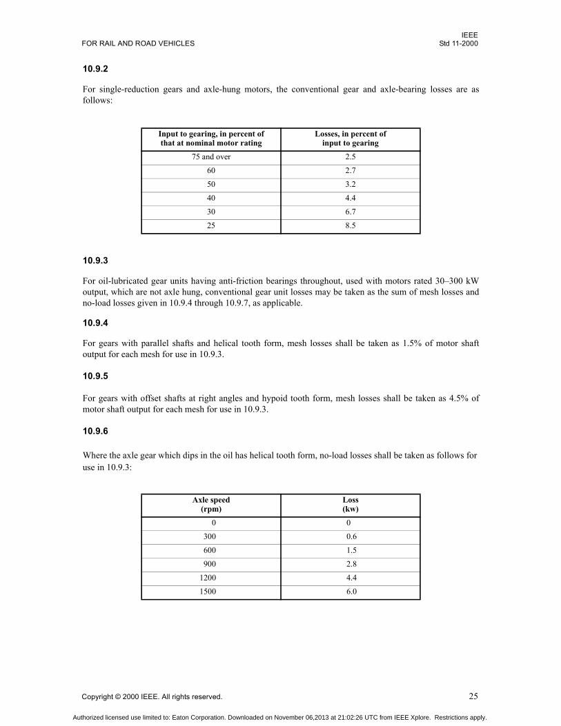
IEEEFOR RAIL AND ROAD VEHICLES Std 11-2000
Copyright © 2000 IEEE. All rights reserved. 25
10.9.2
For single-reduction gears and axle-hung motors, the conventional gear and axle-bearing losses are asfollows:
10.9.3
For oil-lubricated gear units having anti-friction bearings throughout, used with motors rated 30300 kWoutput, which are not axle hung, conventional gear unit losses may be taken as the sum of mesh losses andno-load losses given in 10.9.4 through 10.9.7, as applicable.
10.9.4
For gears with parallel shafts and helical tooth form, mesh losses shall be taken as 1.5% of motor shaftoutput for each mesh for use in 10.9.3.
10.9.5
For gears with offset shafts at right angles and hypoid tooth form, mesh losses shall be taken as 4.5% ofmotor shaft output for each mesh for use in 10.9.3.
10.9.6
Where the axle gear which dips in the oil has helical tooth form, no-load losses shall be taken as follows for use in 10.9.3:
Input to gearing, in percent ofthat at nominal motor rating
Losses, in percent ofinput to gearing
75 and over 2.5
60 2.7
50 3.2
40 4.4
30 6.7
25 8.5
Axle speed(rpm)
Loss(kw)
0 0
300 0.6
600 1.5
900 2.8
1200 4.4
1500 6.0
Authorized licensed use limited to: Eaton Corporation. Downloaded on November 06,2013 at 21:02:26 UTC from IEEE Xplore. Restrictions apply.

IEEEStd 11-2000 IEEE STANDARD FOR ROTATING ELECTRIC MACHINERY
26 Copyright © 2000 IEEE. All rights reserved.
10.9.7
Where the axle gear which dips in the oil has hypoid tooth form, no-load losses shall be taken as follows foruse in 10.9.3:
11. External power systems
11.1 Supply voltage
The standard values for supply voltage at the vehicle power collector are shown in Tables 4 and 5 and arelimited in number for standardization purposes.
The maximum operating voltage on single-phase ac systems is the same as the normal upper operatingvoltage, except for 25 Hz systems. For 25 Hz systems the maximum operating voltage may somewhatexceed the normal upper operating voltage.
Axle speed(rpm)
Loss(kw)
0 0
300 1.8
600 5.0
900 9.25
Table 4Supply voltages for dc systems
Minimum operatingvoltage
(V)
Nominal systemvoltage
(V)
Maximum operatingvoltage
(V)
400 600 720
500 750 900
1000 1500 1800
2000 3000 3600
Table 5Supply voltages for single-phase ac systems
Frequency(Hz)
Minimumoperating
voltage(V)
Normallower
operatingvoltage
(V)
Nominalsystemvoltage
(V)
Normalupper
operatingvoltage
(V)
25 8 000 9 500 11 000 12 100
50 or 60 8 750 10 000 12 500 13 750
50 or 60 17 500 20 000 25 000 27 500
50 or 60 35 000 40 000 50 000 55 000
Authorized licensed use limited to: Eaton Corporation. Downloaded on November 06,2013 at 21:02:26 UTC from IEEE Xplore. Restrictions apply.

IEEEFOR RAIL AND ROAD VEHICLES Std 11-2000
Copyright © 2000 IEEE. All rights reserved. 27
11.2 Propulsion performance voltage
Each user may specify a voltage for the calculation of characteristics and performance. This voltage willusually be the average voltage to be expected at the vehicle power collector on that users system. Thisvoltage may differ from the nominal system voltage. Above and below this voltage, propulsion performancemay vary inherently, or it may be controlled in a manner subject to agreement between manufacturer anduser. Alternatively, propulsion performance may be regulated over a range of collector voltages such as±10% from the nominal system voltage. Regulation of constant propulsion performance over wide supplyvoltage range generally is not desirable.
11.3 Supply characteristics
Because of the adverse effect on equipment size and system efficiency, the overall range of operatingvoltage specified by the purchaser should not exceed the range of the standard voltages of Tables 4 and 5,nor should the propulsion performance voltage be made unreasonably low. Operation at or near theminimum operating voltage is assumed to be of limited duration and extent. Under conditions of low supplyvoltage, the power that can be supplied by the line is limited, and a priority of needs should be established.Any vital auxiliary machine shall have adequate output to permit operation of the vehicle at any value ofsupply voltage within the range specified in the contract. Reduced performance may be expected at low linevoltage. The means of reducing nonvital loads under adverse supply conditions will depend on theircharacteristics and control, and is subject to agreement between manufacturer and purchaser.
11.4 DC systems using regeneration
Regenerative braking of vehicles on dc systems may be expected to increase the line voltage locally. Thedesigned output voltage of the supply substations should be selected so as to permit adequate receptivity forregenerated power within the range of Table 4 where regenerative equipment is expected to be used. Thedesign and application of auxiliary machines should take into account the frequency and duration ofhigh-voltage conditions. The propulsion and other loads should not use voltage-limiting devices that mightdefeat the line receptivity foreseen with regeneration.
12. Terminal marking
12.1 Traction motors
12.1.1 General
Terminal marking for apparatus to which this standard applies distinguishes between traction motors andmachines other than traction motors. The use of suffix numbers for traction motors is reserved for vehicleuse to indicate axle driven or motor location.
12.1.2 Commutator-type traction motors
Armature (connected to a brush holder) A
Armature (connected to a brush holder or through commutating or compensating field AA
Series exciting field F, FF
When commutating field windings are not permanently connected to the armature, the external leads shall be marked C, CC
When compensating field windings are not permanently connected to the armature, the external leads shall be marked D, DD
Shunt or separate exciting field S, SS
Authorized licensed use limited to: Eaton Corporation. Downloaded on November 06,2013 at 21:02:26 UTC from IEEE Xplore. Restrictions apply.

IEEEStd 11-2000 IEEE STANDARD FOR ROTATING ELECTRIC MACHINERY
28 Copyright © 2000 IEEE. All rights reserved.
When a compensating winding or commutating winding has no significance outside the machine, the AAmarking may be applied to the free end of this field winding.
When two field windings are connected together inside a machine and a tap is brought out, the tap will carrythe letter of the field having the greater significance outside of the machine.
When no internal connections are made to the armature, or internally connected fields are divided on eachside of the armature, the A and AA markings will be arbitrary. When fields are internally connected to oneside of the armature, the A lead shall be connected directly to the brush holder.
The correct polarity of the commutating and compensating field is given by lettering sequence A-AA, C-CC,D-DD.
If more than one field of any type is present, the first shall have no suffix, the second X, the third Y, and thefourth Z.
Midtaps shall be marked with the associated field markings (single letter) and the suffix M for the first, MMfor the second, etc.
For a traction motor with armature and field polarities A-AA and F-FF (S-SS), rotation will becounterclockwise when looking at the commutator end of the machine.
12.1.3 Noncommutator-type traction motors
The standard line vector rotation is counterclockwise.
The standard phase sequence is A-B-C.
For a traction motor with counterclockwise line vector rotation and phase sequence A-B-C, rotation will becounterclockwise when looking at the end opposite the drive end of the machine.
12.2 Rotating machines other than traction motors
12.2.1 Commutator-type machines other than traction motors
Stator windings line leads TA, TB, TC
Stator winding neutral TO
Exciting winding F, FF
Armature (connected to a brush holder) A1
Armature (connected to a brush holder or through commutating or compensating field) A2
Series exciting field S1, S2
When commutating field windings are not permanently connected to the armature, the external leads shall be marked C1, C2
When compensating field windings are not permanently connected to the armature, the external leads shall be marked D1, D2
Shunt or separate exciting field F1, F2, F3
Cranking field K1, K2
Authorized licensed use limited to: Eaton Corporation. Downloaded on November 06,2013 at 21:02:26 UTC from IEEE Xplore. Restrictions apply.

IEEEFOR RAIL AND ROAD VEHICLES Std 11-2000
Copyright © 2000 IEEE. All rights reserved. 29
When a compensating winding or commutating winding has no significance outside the machine, the A1 orA2 marking may be applied to the free end of this field winding.
When two field windings are connected together inside a machine and a tap is brought out, the tap will carrythe letter of the field having the greater significance outside of the machine.
When no internal connections are made to the armature or internally connected fields are divided on eachside of the armature, the A1 and A2 markings will be arbitrary. When fields are internally connected to oneside of armature, the A1 lead shall go directly to the brush holder.
The correct polarity of the commutating and compensating field is given by lettering sequence A1A2,C1C2, D1D2.
If more than one field of any type is present, the first shall have suffixes 1 and 2, the second 3 and 4, the third5 and 6, etc.
Midtaps shall be marked with the associated field marking letter and the suffix M1 for the first, M2 for thesecond, etc.
For a motor with armature and field polarities A1A2 and F1F2 (S1S2), rotation will be counterclockwisewhen looking at the commutator end of the machine.
The sequence of armature and field polarities of A1A2 and S1S2 indicates a cumulative series field for amotor and a differential series field for a generator with counterclockwise rotation.
12.2.2 Noncommutator-type machines other than traction motors
The standard line vector rotation is counterclockwise.
The standard phase sequence is 123.
For a polyphase machine with counterclockwise line vector rotation and phase sequence 123, rotation willbe counterclockwise when looking at the end opposite the drive and of the machine.
For a single-phase machine, rotation will be counterclockwise when looking at the end opposite the driveend when even-numbered main winding leads and odd-numbered start winding leads go to the same side ofthe line.
Stator winding line leads (polyphase) T1, T2, T3
Dual winding, if used (polyphase) T4, T5, T6
Stator winding neutral T0
Run winding (singlephase) T1, T2
Start winding (singlephase) T5, T6
Output terminals of alternator having integral rectifiers +,
Exciting winding F1, F2
Authorized licensed use limited to: Eaton Corporation. Downloaded on November 06,2013 at 21:02:26 UTC from IEEE Xplore. Restrictions apply.

IEEEStd 11-2000 IEEE STANDARD FOR ROTATING ELECTRIC MACHINERY
30 Copyright © 2000 IEEE. All rights reserved.
12.3 Reactors
12.3.1 Inductive shunts S, SS
Current going in single-lettered terminals gives cumulative magnetization.
12.3.2 Reactors other than inductive shunts T1, T2,
Current going in odd-numbered terminals gives cumulative magnetization.
12.4 Connection diagrams
In addition to terminal markings, connection diagrams for machines shall show, as applicable, a direction ofrotation and the corresponding brush holder polarities (+, ), field polarities (N, S), direction of current, andphase sequence.
Rotation shall be counterclockwise if a two-rotation machine or if normal rotation is counterclockwise. Ifnormal rotation is clockwise, this rotation should be shown. Rotation is as observed from the commutatorend, or other than the drive end if noncommutator machine.
12.5 Additional terminals
Terminals for added control windings, auxiliary windings, sensors, etc., shall be marked with anomenclature that will not be confused with main windings as identified above.
13. Mechanical measurements
13.1 Commutator trueness
By special agreement between manufacturer and purchaser, measurement of the commutator surface may bemade part of the routine test. Measurement is to be made at very low speed and at ambient temperature. Oneof the following options must be agreed on for the measurement:
13.1.1
In the assembled machine.
13.1.2
On the armature with its own bearings and bearing housings.
13.1.3
On the armature supported on its shaft bearing fits.
13.1.4
On the armature supported on its shaft centers.
Authorized licensed use limited to: Eaton Corporation. Downloaded on November 06,2013 at 21:02:26 UTC from IEEE Xplore. Restrictions apply.
IEEEFOR RAIL AND ROAD VEHICLES Std 11-2000
Copyright © 2000 IEEE. All rights reserved. 31
Single bearing machines require special consideration of support. The recommended limits of total indicatorrunout (TIR), referred to the commutator peripheral velocity at the maximum design speed (Clause 9), are asfollows:
Only gradual changes in commutator surface are permitted. Due to practical limitations, measurement of thebar-by-bar profile is not recommended on a routine basis.
13.2 Vibration
13.2.1 General
Vibration may be measured by special agreement between manufacturer and purchaser. Measurement is tobe made on the assembled machine, running light, less any gearing, blowers, etc. Single bearing machinesrequire special consideration of support.
13.2.2 Vibration type test
The machine shall be supported on resilient material having a low natural frequency. The recommendedlimit of the velocity of vibration in any axis at any speed within the maximum design speed (Clause 9) is7.6 mm/s (0.3 in/s).
13.2.3 Vibration routine test
Supported in the test stand, the machine shall be run at a speed that avoids stand resonance. The limits ofvibration shall be based on that of machines having had type tests, as run under routine test conditions.
13.3 Sound
By special agreement between manufacturer and purchaser, audible sound measurement may be required.The principles of IEEE Std 85-1973 [B2] or ANSI S12.12-1992 [B1], are recommended.
Using IEEE Std 851973 [B2], the recommended limits of mean sound pressure level for a machine of 150kW continuous rated output or less, at a distance of 4.5 m (15 ft), are 78 dBA for a separately ventilatedmachine and 105 dBA for a self-ventilated machine at or below the maximum design speed (Clause 9).Essentially unidirectional self-ventilated machines may be expected to produce significantly lower soundlevels. These values are to be reduced by 3 dBA if significant pure tones exist in the range from 300 Hz to4000 Hz. For this purpose pure tones are considered significant if any one-third-octave-band sound pressurelevel is 5 dB or more above the average of the two adjacent one-third-octave bands. These values are formachines without gears. For inverter driven induction motors, test shall be made with inverter drive at mul-tiple speeds.
Separate ventilation blowers are to be sufficiently isolated not to influence the results. A no-load test isrecommended. If loading is specified, two identical machines may be directly coupled and the limitingvalues for the two machines together increased by 3 dBA. If limits lower than those recommended arespecified, machine size, weight, and enclosure may be expected to increase.
Maximum design speed Maximum TIR
Below 44 m/s (8500 ft/min) 0.05 mm (0.002 in)
44 m/s (8500 ft/min) and over 0.025 mm (0.001 in)
Authorized licensed use limited to: Eaton Corporation. Downloaded on November 06,2013 at 21:02:26 UTC from IEEE Xplore. Restrictions apply.

IEEEStd 11-2000 IEEE STANDARD FOR ROTATING ELECTRIC MACHINERY
32 Copyright © 2000 IEEE. All rights reserved.
13.4 Shaft voltage
By special agreement between manufacturer and purchaser, shaft voltage or current may be measured. Thisis an investigative test.
Authorized licensed use limited to: Eaton Corporation. Downloaded on November 06,2013 at 21:02:26 UTC from IEEE Xplore. Restrictions apply.

IEEEFOR RAIL AND ROAD VEHICLES Std 11-2000
Copyright © 2000 IEEE. All rights reserved. 33
Annex A
(informative)
Bibliography
[B1] ANSI S12.121992 (Reaff 1997), Engineering method for the determination of sound power levels ofnoise sources using sound intensity.3
[B2] IEEE Std 851973 (Reaff 1986), IEEE Test procedure for airborne sound measurements on rotatingelectric machinery.
[B3] IEEE Std 1001996, IEEE Standard Dictionary of Electrical and Electronics Terms.
3ANSI publications are available from the Sales Department, American National Standards Institute, 11 West 42nd Street, 13th Floor,New York, NY 10036, USA (http://www.ansi.org/).
Authorized licensed use limited to: Eaton Corporation. Downloaded on November 06,2013 at 21:02:26 UTC from IEEE Xplore. Restrictions apply.