
A Study on the Improvement of the INPRO Proliferation ...
52
KAERI/TR-4097/2010 기술보고서 A Study on the Improvement of the INPRO Proliferation Resistance Assessment Methodology (INPRO 핵확산저항성 평가방법론 개선연구) 2010. 7
Transcript of A Study on the Improvement of the INPRO Proliferation ...

KAERI/TR-4097/2010
기술보고서
A Study on the Improvement of the INPRO Proliferation Resistance Assessment Methodology
(INPRO 핵확산저항성 평가방법론 개선연구)
2010. 7

ii
제 출 문 한국원자력연구원장 귀하 본 보고서를 2010 년도 “선진 미래형 원자력안전관리체계 구축” 과제 (세부과제 “국제
규범에 입각한 핵비확산성 평가방법론 개발”)의 기술보고서로 제출합니다.
2010. 7
주 저 자: 장홍래 공 저 자: 고원일
KAERI/TR-4097/2010
iii
Contents
List of Tables .................................................................................................................................. v
List of Figures ............................................................................................................................... vi
1. Introduction ................................................................................................................................ 1
2. Proposed Systematic Approach for Acquisition/Diversion Pathway Analysis .......................... 1
2.1 Threat Definition ................................................................................................................ 1
2.2 Possible Proliferation Strategies of the host State.............................................................. 2
2.3 Proposed Systematic Approach for Acquisition/Diversion Pathway Analysis .................. 3
3. Coarse Acquisition/Diversion Pathway Analysis for a DUPIC Fuel Cycle .............................. 5
3.1 Definition of Proliferation Objectives and Technical Capabilities of the host State ......... 5
3.2 Identification of a Nuclear Energy System, the DUPIC Fuel Cycle .................................. 6
3.3 Identification of Specific INS Elements............................................................................. 6
3.4 Identification of Proliferation Targets in the DUPIC Fuel Cycle ...................................... 9
3.5 Coarse Pathway Analysis of the DUPIC Fuel Cycle ....................................................... 10
3.6 Description of Coarse Acquisition/Diversion from the DUPIC Fuel Cycle .................... 17
4. Detailed pathway Analysis for the Diversion of Fresh DUPIC Fuel from Storage Pool ......... 18
4.1 Design and Process Information on the Fuel Storage Pool of the DUPIC Fuel Cycle .... 18
4.2 IAEA Safeguards Measures applicable to a DUPIC Power Plant ................................... 20
4.2.1 IAEA Inspections for Material Control and Accounting (MC&A) at the Close of Material Balance Period ......................................................................................... 21
4.2.2 Containment and Surveillance System ................................................................... 21
4.3 Acquisition/Diversion Strategy of the State for fresh DUPIC Fuel Bundles ................... 23
4.4 Event Sequence Diagram (ESD) for Diversion of fresh DUPIC Fuel Bundles from the Storage Bay ...................................................................................................................... 24
4.5 Detailed Acquisition/Diversion Pathway Analysis for fresh DUPIC Fuel from the DUPIC Fuel Storage Pool, by using User Requirements 1, 2 and 3 ................................ 26
4.5.1 Evaluation of UR1 on State’s Commitments and Implementation ........................ 26
4.5.2 Evaluation of UR2 on Attractiveness of Nuclear Material (fresh DUPIC Fuel) and Technology ............................................................................................................. 27
4.5.3 Evaluation of UR3 on Detectability and Difficulty of Diversion of Nuclear Material .................................................................................................................. 30
4.6 Evaluation of UR4 on Multiplicity and Robustness of Barriers at each Segment of the Diversion Pathway ........................................................................................................... 33
4.6.1 Evaluation of Multiplicity of Proliferation Barriers............................................... 33
4.6.2 Evaluation of Robustness of Proliferation Barriers ............................................... 37
4.7 Evaluation of User Requirement 5 on Optimization of Design ....................................... 38
5. Interactions with the Proliferation Resistance & Physical Protection Working Group (PRPPWG) of Generation IV International Forum (GIF) ........................................................ 39

iv
6. Summary / Conclusions ........................................................................................................... 42
REFERENCES ............................................................................................................................. 44

v
List of Tables Table 1 : Three-year Project with Three Stages ............................................................................. 2
Table 2 : Threat Definition Summary ............................................................................................ 3
Table 3 : Technical Specifications of Wolsong CANDU-6 Unit 1 ................................................ 7
Table 4 : Safeguards Significant Quantities for Target Materials (1SQ) ....................................... 9
Table 5 : Technical Specifications of Spent PWR Fuel and DUPIC Fuel Bundles ....................... 9
Table 6 : Diversion Targets and Possible Diversion Points at the DUPIC Fuel Cycle ................ 10
Table 7 : Pathway Analysis Worksheet for the DUPIC Fuel Fabrication Facility ...................... 13
Table 8 : Pathway Analysis Worksheet for Transport of DUPIC Fuel Bundles from the DUPIC Fuel Fabrication Facility to the DUPIC Power Station .................. 14
Table 9 : Pathway Analysis Worksheet for the CANDU Power Station ..................................... 15
Table 10 : Pathway Analysis Worksheet for the Transport of Spent DUPIC Fuel Bundles from the CANDU Power Station to an AFR Interim Storage Facility ............................... 16
Table 11 : Pathway Analysis Worksheet for the AFR Dry Storage Facility ............................... 16
Table 12 : Pathway Analysis Worksheet for Transport of Spent DUPIC Fuel Bundles from the Interim Dry Storage to the Permanent Disposal Repository ...................................... 16
Table 13 : Pathway Analysis Worksheet for the Permanent Disposal Repository ...................... 17
Table 14 : Evaluation for INPRO User Requirement 1 ............................................................... 26
Table 15 : Evaluation for INPRO User Requirement 2 ............................................................... 29
Table 16 : Evaluation for INPRO User Requirement 3 ............................................................... 32
Table 17 : Multiplicity of Proliferation Barriers against Diversion of fresh DUPIC Fuel .......... 34
Table 18 : Evaluation Criteria for Multiplicity of Proliferation Barriers in UR4 ........................ 36
Table 19 : Evaluation Criteria for Robustness of Proliferation Barriers in UR4 ......................... 37

vi
List of Figures Figure 1 : Proliferation strategy of the host State .......................................................................... 3
Figure 2 : A systematic approach of acquisition/diversion pathway analysis ............................... 4
Figure 3 : Schematic showing the three levels of proliferation barriers ........................................ 5
Figure 4 : DUPIC fuel fabrication process ..................................................................................... 7
Figure 5 : IAEA safeguards system and flow of DUPIC fuel bundles in a CANDU-6 reactor ..... 8
Figure 6 : Material flow in the DUPIC fuel cycle ........................................................................ 10
Figure 7 : Nuclear material accounting scheme of a DUPIC fuel fabrication facility ................. 12
Figure 8 : Material flow at a DUPIC power plant ........................................................................ 19
Figure 9 : Physical dimension of fresh DUPIC fuel ..................................................................... 20
Figure 10 : Schematic of transportation of spent DUPIC fuel to the dry storage ........................ 23
Figure 11 : Diversion scenario for fresh DUPIC fuel bundles in the DUPIC power plant .......... 24
Figure 12 : Scenario-1 for the diversion of fresh DUPIC fuel bundles from the storage bay ..... 25
Figure 13 : Interaction of INPRO and GIF Proliferation Resistance Methodologies .................. 39
Figure 14 : Dependencies of Measures in the GIF PR Evaluation Methodology and their Relation to INPRO User Requirements/Indicators ............................................ 41

1
1. Introduction
The INPRO proliferation resistance evaluation methodology provides both a framework for assessing proliferation resistance (PR), and guidance to improve the proliferation resistance of an innovative nuclear energy system (INS). It is based on the basic principle that proliferation resistance intrinsic features and extrinsic measures shall be implemented throughout the full life cycle of the INS to help ensure that INS will continue to be an unattractive means to acquire fissile material for a nuclear weapons program1. The methodology has one Basic Principle and five User Requirements, along with relevant Criteria, Indicators, Evaluation Parameters, etc.
The assessment indicators and procedures for the first three User Requirements regarding States’ commitments, attractiveness of nuclear material and technology, and difficulty and detectability of diversion, have been established through the Korean national case studies on DUPIC (Direct Use of spent PWR fuel In CANDU reactors) fuel cycle and by various consultancy meetings. However, the assessment indicators and procedure for User Requirement 4 (UR4) regarding multiplicity and robustness of barriers against proliferation (innovative nuclear energy systems should incorporate multiple proliferation resistance features and measures) still needs to be developed. In this regard, the INPRO Phase 2 Collaborative Project on “Proliferation Resistance: Acquisition/Diversion Pathway Analysis (PRADA)” was proposed by the Republic of Korea as a Collaborative Project (CP) Program at the 10th INPRO Steering Committee Meeting held in Vienna in December 20062.
The kick-off meeting of the INPRO Phase 2 Collaborative Project on PRADA was held in Vienna from 19-20 November 2007, and several follow-on consultancy meetings have been held in Vienna, once in Jeju City (Korea) and Vancouver (Canada) based on the three-year project schedule shown in Table 1. One of the decisions taken in the early consultancy meeting and reinforced afterwards has been to develop procedures and metrics for the evaluation of UR4 benefitting from the work done in the context of the Proliferation Resistance and Physical Protection (PR&PP) Working Group of the Generation IV International Forum (GIF).
2. Proposed Systematic Approach for Acquisition/Diversion Pathway
Analysis 2.1 Threat Definition
The objective of the host State is to acquire nuclear material that could be used for nuclear explosive devices (NEDs). It was assumed that the actor, i.e., proliferant State, is an industrialized non-nuclear weapon State that has indigenous uranium resources, physical control over the commercial nuclear energy system and nuclear materials being evaluated, declared facilities and materials that are subject to international safeguards under a Comprehensive Safeguards Agreement (CSA) and the Additional Protocol (AP) in force.
1 International Atomic Energy Agency, Guidance for the Application of an Assessment Methodology for Innovative Nuclear Energy Systems, INPRO Manual – Proliferation Resistance, Volume 5 of the Final Report of Phase 1 of the International Project on Innovative Nuclear Reactors and Fuel Cycles(INPRO), IAEA-TECDOC-1575, IAEA Vienna (2007). 2 International Atomic Energy Agency, “Terms of Reference for the INPRO Collaboration Project, Proliferation Resistance: Acquisition/Diversion Pathway Analysis,” IAEA, Vienna (5 May 2008).

2
Table 1 : Three-year Project with Three Stages
Goal Work Scope 1st Year 2nd Year 3rd Year
1/4 2/4 3/4 4/4 1/4 2/4 3/4 4/4 1/4 2/4 3/4 4/4
Selection of Prospective Pathways
Description of proliferation objectives
Study of possible strategies of proliferation
Systematic approach for possible pathways
Analysis of Pathways
Characteristics of design and process information of facility
Development of logic trees (or, probability approach, if necessary)
Evaluation of each process flow of the prospective pathway
Assessment of Multiplicity &
Robustness
Evaluation of multiplicity & robustness of barriers
Review and recommendation of Assessment methodology
2.2 Possible Proliferation Strategies of the host State
The DUPIC fuel cycle is comprised of several system elements including the DUPIC fuel fabrication facility, a CANDU reactor, spent fuel interim storage facility, a final repository. The proliferation target could be nuclear material, equipment and processes that can be misused for the production of undeclared nuclear weapons usable materials, or equipment and technology that can be replicated in an undeclared facility. In the case study, only the first, diversion of fissile nuclear materials from the DUPIC fuel cycle facility is considered, although equipment and technologies in the DUPIC fuel cycle may be misused. The host State may divert nuclear material from the DUPIC fuel cycle in an abrupt manner or in a protracted way depending upon the circumstances.
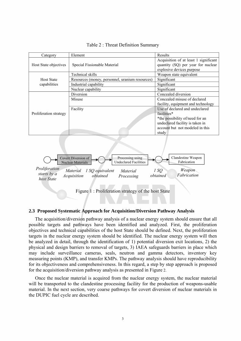
Table 2 summarizes the threat definition result and possible proliferation strategies. One strategy that a proliferant State could use to manufacture nuclear weapons is shown in Figure 1: covertly acquire fissile nuclear material from the DUPIC fuel cycle, process acquired material at the undeclared facilities, and fabricate nuclear weapons.
3
Table 2 : Threat Definition Summary
Category Element Results
Host State objectives Special Fissionable Material Acquisition of at least 1 significant quantity (SQ) per year for nuclear explosive devices purpose
Host State capabilities
Technical skills Weapon state equivalent Resources (money, personnel, uranium resources) Significant Industrial capability Significant Nuclear capability Significant
Proliferation strategy
Diversion Concealed diversion Misuse Concealed misuse of declared
facility, equipment and technology Facility Use of declared and undeclared
facilities* *the possibility of/need for an undeclared facility is taken in account but not modeled in this study
2.3 Proposed Systematic Approach for Acquisition/Diversion Pathway Analysis
The acquisition/diversion pathway analysis of a nuclear energy system should ensure that all possible targets and pathways have been identified and analyzed. First, the proliferation objectives and technical capabilities of the host State should be defined. Next, the proliferation targets in the nuclear energy system should be identified. The nuclear energy system will then be analyzed in detail, through the identification of 1) potential diversion exit locations, 2) the physical and design barriers to removal of targets, 3) IAEA safeguards barriers in place which may include surveillance cameras, seals, neutron and gamma detectors, inventory key measuring points (KMP), and transfer KMPs. The pathway analysis should have reproducibility for its objectiveness and comprehensiveness. In this regard, a step by step approach is proposed for the acquisition/diversion pathway analysis as presented in Figure 2.
Once the nuclear material is acquired from the nuclear energy system, the nuclear material will be transported to the clandestine processing facility for the production of weapons-usable material. In the next section, very coarse pathways for covert diversion of nuclear materials in the DUPIC fuel cycle are described.
Processing using Undeclared Facilities
Clandestine Weapon Fabrication
Covert Diversion of Nuclear Materials
Proliferation starts by a host State
Material Acquisition
1 SQ equivalent obtained
Material Processing
1 SQ obtained
Weapon Fabrication
Figure 1 : Proliferation strategy of the host State

4
Figure 2 : A systematic approach of acquisition/diversion pathway analysis
Identify Innovative Nuclear Energy System (INS) to be used as material source - Establish Boundary conditions of INS considered/assessed including operational state
Qualitative acquisition/diversion pathway analysis - Identify and describe plausible acquisition strategies/coarse pathways including
concealment strategies for each target - Specify possible means of acquisition of the targets including diversion points - Identification of proliferation resistance intrinsic features and extrinsic measures
relevant for the proliferation pathway considered - Check whether all identified pathways are covered by safeguards measures - Perform qualitative pathway analysis - Examine multiplicity and robustness of barriers - Select subset of pathways for detailed analysis
Identify and categorize proliferation targets (Materials, equipment and processes, equipment and technology)
- Define any needed clandestine facilities
Identify State specific conditions, capabilities, institutional arrangements in place and plausible strategies
Identify specific INS elements
Analyze INS elements to identify plausible acquisition/diversion pathways - Decomposition of the INS into sub-elements - Operational states of the system required for acquisition of the targets - Identify different process steps in each sub-element
Detailed acquisition/diversion pathway analysis using logic diagrams. When done: - Identify additional proliferation resistance intrinsic features and extrinsic measures
This is an iterative process

5
3. Coarse Acquisition/Diversion Pathway Analysis for a DUPIC Fuel Cycle The degree of proliferation resistance results from a combination of, inter alia, technical
design features, operational modalities, institutional arrangements and safeguards measures3. The effectiveness of barriers to proliferation can be categorized as: (1) technical difficulty in making weapons (as a state level concern, not related to a specific facility), (2) barriers representing the difficulty in handling and processing materials (both at the State and at the facility level): (3) barriers leading to difficulty/detectability and safeguardability (at a specific facility related pathway level). Therefore, there are three levels of INPRO proliferation resistance assessment with associated indicators: State level, INS level and facility-level including facility specific pathways, as shown in Figure 3.
In this section, the DUPIC fuel cycle has been analyzed using the proposed systematic approach. When determining the barrier function of intrinsic features, the following aspects are to be considered:
1) Is an intrinsic feature relevant to the pathway considered?
2) Is an intrinsic feature associated with the level of assessment (see Fig.2)?
3.1 Definition of Proliferation Objectives and Technical Capabilities of the host State
As described in Section 2, the proliferation objective of the host State is to acquire at least 1 SQ of nuclear material from the DUPIC fuel cycle that could be used for nuclear explosive devices. The technical capabilities of the host State are summarized in Table 2.
3 International Atomic Energy Agency, Proliferation Resistance Fundamentals for Future Nuclear Energy Systems, IAEA STR-332, IAEA Department of Safeguards, IAEA, Vienna (2002)
UR2: Low Attractiveness of Material and Technology (State/INS/Facility Level)
UR3: Diversion Difficult and Detectable (Facility Level)
UR4: Multiple Barriers to Proliferation
UR1: Legal Framework for Nonproliferation Established (State Level)
UR5: Costs to be Optimized
Figure 3 : Schematic showing the three levels of proliferation barriers

6
3.2 Identification of a Nuclear Energy System, the DUPIC Fuel Cycle
The basic concept of a DUPIC fuel cycle is to fabricate CANDU nuclear fuel from PWR spent fuel using dry thermal/mechanical processes without separating any fissile material, and then use the fabricated DUPIC fuel in a CANDU reactor. It is assumed that the host State will divert fissile nuclear material from the DUPIC fuel cycle for the manufacture of nuclear explosive devices.
3.3 Identification of Specific INS Elements
The DUPIC fuel cycle4 is composed of 1) an on-site spent fuel storage facility at the PWR power plant, 2) a DUPIC fuel fabrication facility that will extract fuel material from spent PWR fuel, perform the OREOX treatment for pelletizing and then fabricate DUPIC fuel, 3) a CANDU reactor, 4) an interim spent fuel dry storage facility, and 5) a final repository. The reference feedstock for the DUPIC fuel cycle are the Korean Yonggwang Nuclear Station Unit 1&2’s 17x17 standard spent PWR fuel assemblies with a minimum 10 years of cooling time after discharge from the reactor with 35,000 MWD/MTU of final burn-up.
In this case study, a conceptual DUPIC fuel fabrication facility with a throughput of 400 MTHM/yr is postulated as shown in Figure 4. The facility is assumed to meet international requirements for safety and security, as well as all IAEA requirements for nuclear material safeguards under the Comprehensive Safeguards Agreement of the IAEA (INFCIRC/153)5 and Additional Protocol (INFCIRC/540)6.
It is also assumed that this facility has allowances for normal process systems startup and shutdown, scheduled and unscheduled plant equipment maintenance and repair activities, material accountability related tasks that affect plant operation, and any scheduled plant-side outage period for major systems refurbishing activities. Run-outs will be performed at the completion of each production campaign. Cleanouts will also be performed several times per year.
The Wolsong CANDU-6 Power Plant (Unit 1) was selected as the reference plant for the PRADA case study. A site visit was made to the plant in July 2008 to study the IAEA safeguards measures in a CANDU reactor, and identify possible diversion routes for DUPIC fuel bundles. Table 3 shows technical specifications of Wolsong Unit 1, and Figure 5 shows the principal safeguards measures in a typical CANDU-6 reactor7, including the flow of DUPIC fuel bundles.
4 W.I. Ko, H.B. Choi, and M.S. Yang, Cost Evaluation of a Commercial-Scale DUPIC Fuel Fabrication Facility (Part II) – Preliminary Conceptual Design, KAERI/TR-1373/99 (Rev.1), Korea Atomic Energy Research Institute (2005). 5 International Atomic Energy Agency, The Structure and Content of Agreements between the Agency and States required in connection with the Treaty on the Non-proliferation of Nuclear Weapons, INFCIRC/153 (Corrected), June 1972. 6 International Atomic Energy Agency, Model Protocol Additional to the Agreement(s) between States and the International Atomic Energy Agency for the Application of Safeguards, INFCIRC/540 (Corrected), Vienna, September 1997 7 International Atomic Energy Agency, Design Measures to Facilitate Implementation of Safeguards at Future Water Cooled Nuclear Power Plants, TRS-392, IAEA, Vienna (1998)

7
Table 3 : Technical Specifications of Wolsong CANDU-6 Unit 1
Reactor parameters CANDU - Electric power (MWe) - Thermal efficiency (%) - Thermal power (MWt) - Specific power (MWt/ton U) - Load factor - Cycle length (Full Power Day) - No. of fuel assemblies or bundles per core - Loading per core (tU)
713 33
2,161 25.5 0.9 -
4,560 84.7
Characteristic Parameters
CANDU with NU fuel
CANDU with DUPIC fuel
Reactor - Loading per core (tU or tHM) - Annual fuel requirement (tU or tHM)
84.7
94.63
84.7
46.09 Fuel - Initial enrichment - No. of fuel rods per assembly - Discharge burnup (MWD/kgHM)
Nat. U
37 7.5
Spent PWR fuel
43 15.4
Normalization of Fuel - Required fuel amount for 1 GWe-yr (tU or tHM)
132.73
64.64
Figure 4 : DUPIC fuel fabrication process

8
A conceptual away-from-reactor (AFR) spent fuel interim dry storage facility with silos is postulated. The spent DUPIC fuel bundles will be stored at the CANDU power station for some time and then transported to an interim dry storage facility using transport casks, and stored there until final disposition in the spent fuel repository.
The reference spent fuel repository consists of two parts: a surface facility and an underground facility; that is, a room-and-pillar configuration consisting of a series of regularly spaced disposal rooms and connecting channels. The spent fuel bundles are sealed into containers in a fuel packaging facility before transportation to the disposal vault or temporary storage area. The disposal vault is reached and serviced by shafts. The containers are transported into the underground facilities and are placed into vertical boreholes drilled into the floor of the disposal rooms. The container is surrounded by a clay-based buffer material within each borehole. Each disposal room is backfilled with clay-based backfill materials, and the room entrance is sealed when all of the boreholes have been filled.
Figure 5 : IAEA safeguards system and flow of DUPIC fuel bundles in a CANDU-6 reactor
Fresh DUPIC FuelSpent DUPIC Fuel Dry Storage Facility
Fresh DUPIC Fuel Storage

9
3.4 Identification of Proliferation Targets in the DUPIC Fuel Cycle
Table 4 shows the significant quantity for different target materials as defined in the IAEA Safeguards Glossary8. The international safeguards detection goal is to detect the diversion of one significant quantity (SQ) of nuclear material with a certain detection probability within a given time.
In the DUPIC fuel cycle, target materials are uranium and reactor grade plutonium 1) in spent PWR fuel rods/pellets, 2) during the DUPIC fuel fabrication processes, 3) in fresh DUPIC fuel bundles fabricated at the DUPIC fuel fabrication facility, and 4) in spent DUPIC fuel bundles discharged from the CANDU reactor core. Diverted uranium could be used for undeclared enrichment in a clandestine enrichment facility. However, this acquisition path is not considered in this study. To get separated plutonium from the diverted fissile nuclear material the host State has to design and construct a clandestine reprocessing plant. Table 5 shows the plutonium isotopic vector for spent PWR fuel and in fresh and spent elements of the DUPIC fuel cycle. The amount of spent PWR fuel required for 1 SQ of 8kg plutonium is 867 kg, whereas the number of fuel bundles (18 kg HM/bundle) required for 1 SQ are 49 for fresh and 54 for spent DUPIC fuel bundles, respectively.
Table 4 : Safeguards Significant Quantities for Target Materials (1SQ)
Material 1 SQ
Direct use nuclear material
Pu (containing less than 80% 238Pu) 8kg Pu 233U 8kg 233U
HEU (235U≥20%) 25kg 235U
Indirect use nuclear material
Low-enriched, natural and depleted uranium (235U<20%)
75kg 235U (or 10 tonnes NU, or
20 tonnes DU) Thorium 20 tonnes
Table 5 : Technical Specifications of Spent PWR Fuel and DUPIC Fuel Bundles 1) Plutonium isotopes in spent PWR fuel and DUPIC fuel bundles
Isotopes Spent PWR Fuel Fresh DUPIC Fuel Spent DUPIC Fuel
g/MTHM Pu (wt %) g/MTHM Pu (wt %) g/MTHM Pu (wt %)238Pu 1.54E+02 1.7 1.54E+02 1.7 3.88E+02 4.9 239Pu 5.33E+03 59.9 5.33E+03 59.9 3.16E+03 39.7 240Pu 2.20E+03 24.8 2.20E+03 24.8 2.79E+03 35.1 241Pu 7.52E+02 8.4 7.52E+02 8.4 5.24E+02 6.6 242Pu 4.57E+02 5.1 4.57E+02 5.1 1.10E+03 13.8 totPu 8.893E+03 8.89E+03 7.96E+03
Mass of spent PWR fuel for 1 SQ of Pu (8kg Pu) = 866.74 kg ≈ 1.89 spent PWR fuel assemblies
2) Number of fuel bundles for 1 significant quantity of plutonium Fresh DUPIC Fuel Spent DUPIC Fuel
kg HM/bundle 17.64 17.64 Pu content (wt %) 0.923% 0.840%
No. of bundles for one SQ (8kgPu) ~49 ~54
8 International Atomic Energy Agency, IAEA Safeguards Glossary 2001 Edition, International Nuclear Verification Series No.3, Vienna (June 2002).

10
3.5 Coarse Pathway Analysis of the DUPIC Fuel Cycle
The DUPIC fuel cycle was decomposed into several elements to identify potential diversion points. The DUPIC fuel fabrication facility, CANDU power plant, interim dry storage, and permanent disposal repository, are shown in Figure 6. Potential diversion can occur; (1) during transport of nuclear materials (spent PWR fuel assemblies, fresh and spent DUPIC fuel bundles) from one facility to another, (2) from the DUPIC fuel fabrication facility, (3) from the fresh and spent DUPIC fuel storage locations of the CANDU power plant, (4) from an interim dry storage, and (5) from the permanent disposal repository. Table 6 shows the potential diversion targets and facilities that diversion can take place in the DUPIC fuel cycle.
In the analysis of each element, operational state and steps are defined, possible diversion means identified, and potential safeguards barriers to be applied to detect any diversion attempts were considered to derive diversion strategies that the host State could use to divert nuclear materials.
Table 6 : Diversion Targets and Possible Diversion Points at the DUPIC Fuel Cycle
Diversion targets Possible diversion points
1. Spent PWR fuel assemblies 1. During transport of spent PWR fuel assemblies from onsite storage at PWR reactor to the DUPIC fuel fabrication facility
2. Spent PWR fuel rod cuts 2. DUPIC fuel fabrication facility (after shearing step) 3. PWR spent fuel pellets or fuel material stuck on inside of hulls 3. DUPIC fuel fabrication facility (feed line after decladding)
4. DUPIC fuel powder 4. DUPIC fuel fabrication facility (before pelletizing step)
5. Sintered DUPIC fuel pellets 5. DUPIC fuel fabrication facility (before welding stage)
6. Sintered DUPIC fuel elements 6. DUPIC fuel fabrication facility (before welding stage)
7. Fresh DUPIC fuel bundles 7. DUPIC fuel fabrication facility (product line in maintenance cell)8. Transport from DUPIC facility to CANDU power plant 9. Fresh DUPIC fuel storage racks in the fuel storage bay
8. Spent DUPIC fuel bundles
10. Failed DUPIC fuel bundles from the reception bay of the plant 11. Spent DUPIC fuel storage racks of the CANDU power plant 12. Transport from CANDU plant to the Interim Dry Storage 13. Interim Dry Storage 14. Transport from Interim Storage to Permanent Disposal Repository15. Permanent Disposal Repository
DUPIC fuel fabrication
Permanentdisposal
Onsite storage
CANDPWR Fresh DUPIC
Fuel bayInterim storage
Pu
Separation Weapon
Fabrication Nuclear
Weapon
Plausible diversion of nuclear materials
CANDU Power PlantWaste Storage
PWR Power Plant
Spent DUPIC Fuel bay
Figure 6 : Material flow in the DUPIC fuel cycle

11
The strategies that the host State would develop to overcome the IAEA safeguards system in the diversion of nuclear materials are developed in the analysis. For example, an accident can be faked during the transport of nuclear material using the licensed rail-car or truck. The host State could declare fuel failures and remove selected fuel bundles at the DUPIC fuel fabrication facility, or declare short cycled fuel bundles as “failed” fuel and sent to reception bay for subsequent diversion. Concerning the means of removal of nuclear material from system elements, the host State may use internal containers or external shielded containers to remove nuclear materials out of the DUPIC fuel fabrication facility. In such cases the host State could introduce dummy materials into the facility to help overcome the safeguards system.
1) Transport of spent PWR fuel assemblies from the PWR onsite storage to the DUPIC fuel fabrication facility
The spent PWR fuel assemblies at the PWR onsite storage will be put into transport casks and transported to the DUPIC facility site for DUPIC fuel bundle production. The mode of transport would be by sea at first, followed by licensed rail car or truck transport casks, then unloaded and stored dry at the DUPIC fuel fabrication facility. Two spent PWR fuel assemblies (440.0 kgHM per an assembly) contain one SQ of plutonium. However, the spent PWR transport casks are not deemed viable targets for covert diversion under normal operation, although it is not impossible.
2) DUPIC fuel fabrication facility
The DUPIC fuel fabrication facility is a complete fuel recycling plant with all functions and equipment for processing spent PWR fuel and converting it to DUPIC fuel. It employs only thermal and mechanical processes that recover fissile material remaining in spent PWR fuel for DUPIC fuel. It is assumed that the spent PWR fuel receiving and storage system will accommodate a minimum of three months operational feedstock capacity (about 100 MTHM of spent fuel, or equivalent to 4-5 years output from a PWR power plant). As shown in Figure 4, the non-fuel components required by the DUPIC fuel bundle (e.g., fuel cladding, end caps, spacers, end plates, and dysprosium poison fuel rods) will be fabricated at off-site facilities and shipped to the DUPIC facility.
The DUPIC fuel fabrication facility will contain all support systems (material handling/storage, waste processing, packaging, storage, and utilities) necessary for DUPIC fuel production. Transport casks/packages will have bolted closures to allow unpacking inside the reactor fuel pool prior to loading in the reactor. It is assumed that the storage and transport system will accommodate a minimum of six weeks of DUPIC production output (50 MTHM), and will be based on dry storage technology. It is assumed that the spent fuel is shipped in licensed rail car or truck transport casks, then unloaded and stored dry in a commercially available dry storage system.
It is assumed that nuclear material control and accounting (MC&A) scheme and Containment and Surveillance (C/S) systems which meet IAEA requirements are designed and installed in the DUPIC fuel fabrication facility in order to safeguard the nuclear materials. It will include surveillance cameras, seals, neutron and gamma detectors, inventory key measuring points (KMPs), transfer KMPs, etc. Three material balance areas are defined based on the needs of safeguards as shown in Figure 7.

12
The spent PWR fuel rods extracted from the fuel assembly after disassembling in MBA-1 are
not considered as a material for potential diversion because the undetected removal of fuel rods inside the cladding tubes is extremely unlikely in consideration of the exit locations as well as the physical and design barriers to removal of targets, including safeguards barriers. Nuclear materials for potential diversion from MBA-2 of the DUPIC fuel fabrication facility are: (1) the spent PWR fuel rod cuts after the chopping step, (2) spent PWR fuel pellets after decladding, (3) spent PWR fuel powder feed stock for sintering, (4) sintered DUPIC fuel pellets, and (5) fresh DUPIC fuel bundles produced at the end of the DUPIC fuel fabrication process. There are several operational states in MBA-2: normal operations, maintenance, repair, and testing, but only normal operational phase is considered in the analysis.
In MBA-2, physical inventory taking (PIV) using destructive assay and weighing is carried out at each key measuring point, and the operator and the IAEA share the accounting data. The diversion of rod cuts from MBA-2 using the external shielded containers could use dummy fuel rod cuts introduced in advance into the MBA-2 by defeating the safeguards system, including the cameras. Similarly, diversion of other target materials such as spent PWR fuel pellets after decladding, DUPIC powder feed stock for sintering after OREOX process, sintered DUPIC fuel pellets before welding which can be diverted using internal or external shielded containers, could use dummy fuel materials introduced in advance into the MBA-2.
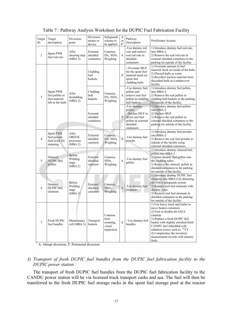
Finally, the fresh DUPIC fuel bundles assembled in MBA-2 will be non-destructively tested for welding quality, dimensions fit, and clearance. Defective fuel bundles will be rejected and forwarded to the repair station or scrap material recycle station for further pertinent processing. The acceptable fuel bundles are subject to item counting for inventory verification, visual inspection and dimension measurement, and will be loaded into baskets and storage containers for transfer to the storage or transport area in MBA-3, and then transported to the CANDU power plant. Table 7 shows pathway analysis worksheet for the DUPIC fuel fabrication facility.
Figure 7 : Nuclear material accounting scheme of a DUPIC fuel fabrication facility
Spent PWR fuel assembly
13
Table 7 : Pathway Analysis Worksheet for the DUPIC Fuel Fabrication Facility
Target ID
Target description
Diversion point
Diversion means or device
Safeguards scheme to be applied
A or P*
Pathway Description Proliferator Actions
2 Spent PWR fuel rod cuts
After shearing step (MBA 2)
External shielded containers
Cameras, DA, NDA, Weighing
A
-Use dummy rod cuts and remove real rod cuts in shielded containers
1) Introduce dummy fuel rod cuts into MBA-2 2) Remove the real rod cuts in external shielded containers to the parking lot outside of the facility
3
Spent PWR fuel pellets or fuel material left in the hulls
After decladding (MBA 2)
Cladding hull baskets
Cameras, DA, NDA,Weighing
P
- Overstate MUF for the spent fuel material stuck on spent fuel cladding hulls
1) Overstate amount of fuel material stuck on inside of the hulls2) Discard hulls as waste 3) Recollect nuclear material from discarded hulls at a undercover facility
Cladding hull baskets
A
-Use dummy fuel pellets and remove real fuel pellets in cladding hull baskets
1) Introduce dummy fuel pellets into MBA-2 2) Remove the real pellets in cladding hull baskets to the parking lot outside of the facility
External shielded containers
P
-Use dummy pellets - Declare MUF to divert real fuel pellets in external shielded containers
1) Introduce dummy fuel pellets into MBA-2 2) Declare MUF 3) Remove the real pellets in external shielded containers to the parking lot outside of the facility
4
Spent PWR fuel powder feed stock for sintering
After OREOX processes (MBA 2)
External shielded canisters
Cameras, DA, NDA,Weighing
A -Use dummy fuel powder
1) Introduce dummy fuel powder into MBA-2 2) Remove the real fuel powder to outside of the facility using external shielded containers
5 Sintered DUPIC fuel pellets
Before Welding stage (MBA 2)
External shielded canisters
Cameras, NDA, Weighing
A -Use dummy fuel pellets
1) Introduce dummy sintered fuel pellets into MBA-2 2) Insert dummy fuel pellets into the cladding tubes 3) Remove the sintered pellets in shielded containers to the parking lot outside of the facility
6 Sintered DUPIC fuel elements
Before Welding stage (MBA 2)
External shielded canisters
Cameras, NDA, Weighing
A -Use dummy fuel elements
1) Introduce dummy DUPIC fuel elements into MBA-2 by defeating the IAEA safeguards system 2) Replace real fuel elements with dummy ones 3) Remove real fuel elements in shielded containers to the parking lot outside of the facility
7 Fresh DUPIC fuel bundles
Maintenance cell (MBA 3)
Transport baskets
Cameras, Item counting, visual inspection
A - Use dummy fuel bundles
1) Use heavy truck and trailer to move basket containers 2) Fool or disable the IAEA cameras 3) Replace a fresh DUPIC fuel basket with slightly enriched fresh CANDU fuel imbedded with radiation source such as 252Cf 4) Compromise the inventory measurement records with dummy fuels
* A: Abrupt diversion, P: Protracted diversion
3) Transport of fresh DUPIC fuel bundles from the DUPIC fuel fabrication facility to the DUPIC power station
The transport of fresh DUPIC fuel bundles from the DUPIC fuel fabrication facility to the CANDU power station will be via licensed truck transport casks and sea. The fuel will then be transferred to the fresh DUPIC fuel storage racks in the spent fuel storage pool at the reactor

14
building. Therefore, the host State must fake an accident to divert nuclear material by replacing real containers with dummy fuel bundle containers.
Table 8 : Pathway Analysis Worksheet for Transport of DUPIC Fuel Bundles from the DUPIC Fuel Fabrication Facility to the DUPIC Power Station
Target ID
Target description
Diversion point
Diversion means of devices
Safeguards scheme to be applied
A or P
Pathway Description Proliferator actions
7
Fresh DUPIC fuel bundles in transport basket containers
During transport
Transport basket containers
Application of seals, item counting
A
- Diversion during transport
1) Fake a collision at sea 2) Declare the sinking of the boat
with DUPIC fuel bundle transport basket containers at the bottom of the sea
3) Replace the recovered transport basket containers with dummy fuel basket containers
4) Compromise the inventory with dummy fuel basket containers
4) CANDU Power Plant
Only steady state operation is considered for the pathway analysis. When the fresh DUPIC fuel bundles arrive at the DUPIC power plant, they are counted and stored in the fuel racks located at the bottom of the spent fuel storage bay, and remotely loaded into the channels of the reactor core by an operator. DUPIC fuel paths and some safeguard equipments in the CANDU reactor are shown in Figure 5.
During normal operation, eight DUPIC fuel bundles per day go through remote visual inspection and dimension measurement before loading. After a fuel manipulator moves the DUPIC fuel bundles from the fuel racks to the conveyor, the fuel bundle is transferred to the discharge bay, and the fuel elevator places the fuel bundle in the fueling machine. The fuel bundles are remotely loaded into the fuel channels selected by the operator. The average fuel residence time in the core is 610 days. The fissile content of the DUPIC fuel is 1.5 wt% when the fuel is loaded, while it is 0.7 wt% when discharged. During the operation, the integrity of the fuel is monitored by the radiation level of the coolant when the fuel channel is open for refueling or inspection. As the fresh fuel bundles are loaded, the spent fuel bundles are automatically discharged from the core and transferred to discharge bay. The spent fuel is then inspected for failure and intact bundles are moved from the discharge bay to the storage bay through the reception bay. The failed fuel bundles are stored in the reception bay until the next move. There is no need for the operator or any other person to physically handle a fuel bundle.
It is not deemed possible to divert nuclear material from inside of the CANDU reactor building during normal operation. Therefore, potential diversion materials in a CANDU power plant are (1) fresh DUPIC fuel bundles on the fresh fuel storage racks, (2) failed DUPIC fuel bundles in the reception bay, and (3) spent DUPIC fuel bundles on the spent DUPIC fuel storage racks in the spent fuel pool. The failed fuel bundles are defined as the fuel that has short residence time in the reactor channel due to damage, or fuel discharged before reaching 75% of expected burn-up.
Because the physical form of the fuel bundles does not change before and after the depletion in the core, there is no loss of fuel material in each transfer step. The spent fuel bay is continuously monitored by CCTV, and IAEA inspection is regularly performed to trace spent fuel movement in the spent fuel storage bay and measure the inventory of DUPIC fuel, including failed fuel in the reception bay, by the item counting. The IAEA safeguards scheme

15
for a CANDU reactor includes advance facility information, containment and surveillance measures, core discharge monitors (CDM), bundle counters (BC), and surveillance in remote data transmission and in an unattended mode. An unattended monitoring scheme (UMS) is also implemented for spent fuel transfers from the fuel storage bay to dry storage.
During normal operation, it is difficult to distinguish fresh DUPIC fuel from spent DUPIC fuel by the core discharge monitor through neutron and gamma radiation measurement. The bundle counter in the discharge bay cannot distinguish between movements of fresh or spent fuels. Therefore, dummy fuel bundles could be used to replace fresh and/or spent DUPIC fuel bundles for diversion. That is, the fresh DUPIC fuel bundles could be replaced with slightly enriched CANDU fuel embedded with a radiation source like 252Cf or 137Cs. Likewise, spent DUPIC fuel and failed DUPIC fuel could be replaced with dummy spent fuel bundles. Dummy fuel bundles are used during maintenance of the fueling machine and system. During either normal or abnormal operation, there is no way that fuel bundles are repositioned without using the fueling machine. Passage to the reactor building is through the equipment door with a lock and through the spent fuel transfer canal. Failed fuel bundles are put into sealed containers and stored in the reception bay for a longer period.
Table 9 : Pathway Analysis Worksheet for the CANDU Power Station
Target ID
Target description Diversion point
Diversion means or devices
Safeguards scheme to be
applied
P or A
Pathway Description Proliferator actions
7 Fresh DUPIC fuel bundles
Fresh DUPIC fuel storage racks
Storage basket containers
Seals, Cameras, NDA with gross neutron monitoring
A
- Replace a fresh DUPIC fuel basket with slightly enriched fresh CANDU fuel imbedded with radiation source
1) Fool or disable the IAEA cameras 2) Replace fresh DUPIC fuel baskets with the baskets of slightly enriched fresh CANDU fuel bundles 3) Compromise the inventory measurement records with dummy fuels bundles 4) Use heavy truck and trailer to move basket containers
8 Spent DUPIC fuel bundles Reception bay
Sealed storage containers
Seals, Cameras, NDA with gross neutron monitoring
A
- Intentionally classify DUPIC fuel in channel ‘failed’ and store in sealed containers
1) Fool or disable the IAEA cameras 2) Replace failed DUPIC fuel bundle containers with dummy fuel bundle containers 3) Compromise the inventory measurement records with dummy fuel bundles 4) Use heavy truck and trailer to move containers
8 Spent DUPIC fuel bundles
Spent fuel storage racks
Transport basket containers
Seals, Cameras, NDA with gross neutron monitoring
A
- Use dummy fuel bundle baskets and remove DUPIC fuel bundles in shielded containers
1) Fool or disable the IAEA cameras 2) Replace spent DUPIC fuel bundles with slightly enriched fresh CANDU fuel bundles imbedded with radiation source such as 252Cf to cheat the re-verification tubes 3) Compromise the inventory measurement records with dummy fuels 4) Use heavy truck and trailer to move basket containers
5) Transport of spent DUPIC fuel bundles from the CANDU power station to an AFR interim storage

16
As in the scenario for transporting fresh DUPIC fuel bundles from the DUPIC fuel fabrication facility to the CANDU power station, the host State will fake an accident to divert spent DUPIC fuel bundles in transport casks.
Table 10 : Pathway Analysis Worksheet for the Transport of Spent DUPIC Fuel Bundles from the CANDU Power Station to an AFR Interim Storage Facility
Target ID
Target description Diversion point
Diversion means or devices
Safeguards scheme to be
applied
A or P
Proliferator actions Pathway Description
8 spent DUPIC fuel bundles
During marine transportation
Transport basket containers
Application of seals, item counting
A - Fake an accident at sea
1) Fake a collision of boats at sea2) Declare loss of spent fuel transport basket containers 3) Replace the recovered fuel bundle basket containers with dummy fuel basket containers 4) Compromise the inventory measurement records with dummy fuel bundle baskets
6) Analysis of an AFR dry storage facility
As the transport basket containers arrive at the AFR storage, they are counted, inspected, and stored in silos or dry vaults. They will be inspected regularly for inventory verification. The storage vaults would have safeguards barriers similar to the onsite spent fuel pool at the CANDU power station. They are continuously monitored by the CCTV and IAEA inspection is regularly performed to trace any spent fuel movement in the storage facility. Therefore, the diversion pathway would be similar to that of the onsite dry storage facility of the CANDU power station.
Table 11 : Pathway Analysis Worksheet for the AFR Dry Storage Facility
Target ID
Target description
Diversion point
Diversion means or devices
Safeguards scheme to be
applied
A or P
Pathway Description Proliferator actions
8 Spent DUPIC fuel bundles in storage baskets
Silos or dry vaults
External transport basket containers
Seals, cameras, NDA with gross neutron monitoring
A - Use dummy fuel
bundles in order to cheat the re-verification tubes
1) Fool or disable the IAEA cameras 2) Use heavy truck and trailer to move basket containers 3) Compromise the inventory measurement records with dummy fuels
7) Transport from an interim dry storage to the permanent disposal repository:
Table 12 : Pathway Analysis Worksheet for Transport of Spent DUPIC Fuel Bundles from the Interim Dry Storage to the Permanent Disposal Repository
Target ID
Target description
Diversion point
Diversion device
Safeguards scheme to be applied
A or P
Pathway Description Proliferator actions
8 Spent DUPIC fuel bundles
During transport using a licensed truck
Transport basket containers
Seals, item counting
A
- Use dummy fuel bundles in storage baskets
1) Fake an accident during the road transportation 2) Replace the fuel bundle transport basket containers with dummy fuel bundle basket containers 3) Compromise the safeguards system with dummy fuel bundle basket containers
8) Permanent disposal repository

17
The reference disposal repository consists of two parts: a surface facility and an underground facility assumed to be a room-and-pillar configuration consisting of a series of regularly spaced disposal rooms and connecting channels. The spent fuel bundles are sealed into containers in a fuel packaging facility before they are transported to the disposal vault or temporary storage area. The disposal vault is reached and serviced by shafts. The containers are transported into the underground facilities and are placed into vertical boreholes drilled into the floor of the disposal rooms. The container is surrounded by the clay-based buffer material within each borehole. Each disposal room is backfilled with clay-based backfill materials, and the room entrance is sealed when all of the boreholes have been filled.
The permanent disposal repository is an item-counting facility and therefore there is no MUF. The plutonium content of the spent DUPIC fuels is ~0.7 wt% and the chemical form of the fuel is oxide. During operation, the history of the spent DUPIC fuel and their containers are continuously traced. The containment/surveillance equipment in all the entrance and exit areas of the disposal facility are installed and material flow is monitored.
Because of the facility characteristics, it is extremely difficult to contact the nuclear material directly during the disposal activities and also difficult to refurbish the packaging and disposal facility for diversion and to install diversion equipment in the disposal facility. But the radiation field gradually becomes lower with time and after hundreds of years, the radiation field will no longer exist. In addition, diversion after the closure of the repository will not be plausible because tunneling work on the surface will easily be detected. Therefore, only diversion during normal operation is considered in this case study.
Table 13 : Pathway Analysis Worksheet for the Permanent Disposal Repository
Target ID
Target description
Diversion point
Diversion means or devices
Safeguards scheme to be applied
A or P
Pathway Description Proliferator actions
8
Spent DUPIC fuel bundles in sealed containers
Temporary storage areas or disposal vaults
External transport basket containers
Seals, cameras A - Use dummy fuel
bundles
1) Fool or disable the IAEA cameras 2) Use heavy truck and trailer to move basket containers 3) Compromise the inventory measurement records with dummy fuel bundles
3.6 Description of Coarse Acquisition/Diversion from the DUPIC Fuel Cycle
Potential diversion scenarios listed in Table 6 have been examined to identify plausible diversion pathways with consideration of exit locations, physical and design barriers to removal of targets, and any safeguards barriers. Intrinsic features were intentionally not considered in the table, but when determining the barrier function of intrinsic features, the following aspects should be considered:
1) Is an intrinsic feature relevant to the pathway considered?
2) Is an intrinsic feature associated with the level of assessment (see Figure 2)?

18
4. Detailed pathway Analysis for the Diversion of Fresh DUPIC Fuel from Storage Pool
The diversion of nuclear material from the fresh DUPIC fuel storage bay was selected for the detailed pathway analysis.
4.1 Design and Process Information on the Fuel Storage Pool of the DUPIC Fuel Cycle
Design and process information of the storage pool from the reference plant, Wolsong CANDU-6 Power Plant Unit 1, was used to analyze the diversion pathway of fresh DUPIC fuel bundles from the fresh fuel storage bay, as follows:
It is assumed that fresh DUPIC fuel bundles fabricated in a fuel fabrication facility with a throughput of 400 MTHM/yr are stored in the fuel storage pool of a DUPIC power plant. The DUPIC power reactor has the same technical specifications as the Wolsong CANDU-6 Power Plant Unit 1.
The fuel storage pool consists of two bays, one for fresh DUPIC fuel bundles (Fresh DUPIC fuel bay) which will be loaded onto the DUPIC power reactor at the loading rate of eight bundles per day, and another for spent DUPIC fuel bundles discharged from the DUPIC power plant (Spent DUPIC fuel bay).
When fresh DUPIC fuel bundles arrive at the DUPIC power plant, they are counted and stored on the fuel trays stored in the fresh DUPIC fuel bay.
Eight fresh DUPIC fuel bundles are daily loaded onto the DUPIC reactor through the existing spent fuel discharge route, which requires a stringent fuel management schedule. These fresh DUPIC fuel bundles are subject to visual inspection and dimension measurement before loading. A fuel manipulator transports fresh DUPIC fuel bundles to the DUPIC reactor core through the discharge bay, i.e., in the reverse way to discharging spent DUPIC fuel from the reactor to the storage pool. The average fuel residence time in the core is 610 days. The fissile content of the DUPIC fuel is 1.5 wt% when it is loaded, while it is 0.7 wt% when discharged.
The spent DUPIC fuel from the reactor is transported to the discharge bay, then to the spent fuel bay in the storage pool. The discharged spent DUPIC fuel will, after 6 years cooling in the pool, be transported to the dry storage facility via a heavy-duty truck until a decision has been made for it to be sent to the repository for final disposal.
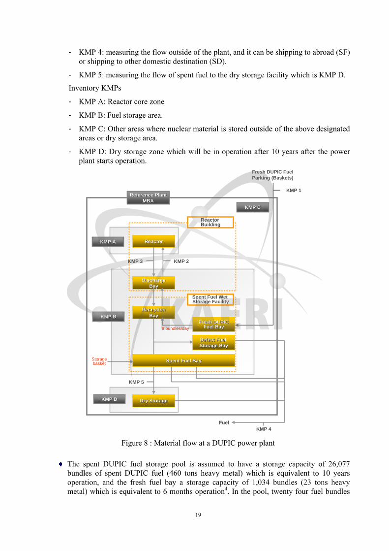
The schematic of material flow at the DUPIC power plant, including designated key measuring points for safeguards purpose, is shown in Figure 8: one material balance area and several key measuring points (KMPs) – five flow KMPs and four Inventory KMPs are as follows:
Flow KMPs
- KMP 1: measuring the receipt of nuclear material from outside of the MBA, i.e., receipt of fresh fuel from the fuel manufacturing plant. It can be the receipt from abroad (RF) or from domestic receipt (RD).
- KMP 2: measuring the daily on-loading rate of fresh fuel to the reactor core.
- KMP 3: measuring the discharge rate of spent DUPIC fuel from the reactor core to the spent fuel storage pool.
19
- KMP 4: measuring the flow outside of the plant, and it can be shipping to abroad (SF) or shipping to other domestic destination (SD).
- KMP 5: measuring the flow of spent fuel to the dry storage facility which is KMP D.
Inventory KMPs
- KMP A: Reactor core zone
- KMP B: Fuel storage area.
- KMP C: Other areas where nuclear material is stored outside of the above designated areas or dry storage area.
- KMP D: Dry storage zone which will be in operation after 10 years after the power plant starts operation.
KMP AKMP A
KMP BKMP B
KMP DKMP D
Reference PlantReference PlantMBAMBA
DischargeDischargeBayBay
Dry StorageDry Storage
Spent Fuel Wet Storage Facility
Reactor Building
KMP 3
KMP 5
KMP 4Fuel
ReactorReactor
Defect Fuel Defect Fuel Storage BayStorage Bay
Fresh DUPICFresh DUPICFuel BayFuel Bay
KMP 2
Fresh DUPIC FuelParking (Baskets)
KMP 1
KMP CKMP C
Spent Fuel BaySpent Fuel Bay
ReceptionReceptionBayBay
8 bundles/day
Storagebasket
Figure 8 : Material flow at a DUPIC power plant
The spent DUPIC fuel storage pool is assumed to have a storage capacity of 26,077 bundles of spent DUPIC fuel (460 tons heavy metal) which is equivalent to 10 years operation, and the fresh fuel bay a storage capacity of 1,034 bundles (23 tons heavy metal) which is equivalent to 6 months operation4. In the pool, twenty four fuel bundles

20
are loaded on each tray, and 19 loaded trays are piled up in a stack. Figure 9 shows physical dimensions of a fresh DUPIC fuel bundle and Table 5 shows technical specifications of spent PWR fuel and fresh and spent DUPIC fuel materials.
Fresh DUPIC Fuel
Dimensions
Bundle diameter 102.5 mm max
Number of large rods (13.5 mm outer dia.) 8
Number of small rods (11.5 mm outer dia.) 35
Length 49.53 mm
Heavy metal weight per bundle 17.64 kg
Bundle weight 23.6 kg
Number of pellets in a large pin 30
Number of pellets in a small pin 36
Pellet density 10.4 (±0.15) g/cm3
1. Zircaloy Bearing Pads2. Zircaloy Fuel Sheath3. Zircaloy End Support Plate4. Fuel Pellets5. Inter Element Spacers
4.2 IAEA Safeguards Measures applicable to a DUPIC Power Plant
The technical objectives of the IAEA safeguards is the timely detection of the diversion of significant quantities of nuclear materials from peaceful nuclear activities to the manufacture of nuclear weapons or of other nuclear explosive devices, and deterrence of such a diversion by the risk of early detection5. IAEA safeguards authorized by Article III.A.5 of the IAEA’s Statute comprise four functions - accountancy, containment and surveillance, inspection/in-field verification, and evaluation of information – and are based on assessments of the correctness and completeness of a State’s declared nuclear material and nuclear-related activities. Verification measures include on-site inspections, visits, and ongoing monitoring and evaluation.
Basically, two sets of measures are carried out in accordance with the types of safeguards agreements in force with a State. One set relates to verifying State reports of declared nuclear material and activities authorized under the comprehensive safeguards agreement pursuant to the NPT, and largely are based on nuclear material accountancy, complemented by containment and surveillance techniques, such as tamper-proof seals and cameras that IAEA installs at nuclear facilities. Another set adds measures to strengthen the IAEA’s inspection capabilities. They include those incorporated in an “Additional Protocol,” a legal document complementing comprehensive safeguards agreements6. The measures enable the IAEA not only to verify the non-diversion of declared nuclear material but also to provide assurance as to the absence of undeclared nuclear materials and activities in a State.
In this study, the IAEA safeguards system as applied to a typical CANDU reactor7 is used for the DUPIC power plant to evaluate the effectiveness of existing safeguards barriers to the diversion of fresh DUPIC fuel bundles from the fresh DUPIC fuel bay.
Figure 9 : Physical dimension of fresh DUPIC fuel

21
4.2.1 IAEA Inspections for Material Control and Accounting (MC&A) at the Close of
Material Balance Period
Accountancy measure of the IAEA requires a State to report the IAEA the types and quantities of nuclear material under its control via an established State System of Accounting for and Control of nuclear materials (SSAC). The SSAC activities include confirmation of design information verification (DIV), physical inventory taking (PIT), ad hoc inspection, regular inspection, and special inspection. Records and reports that a State provides to the Agency include:
- General ledger for each KMP - Inventory change records - Physical Inventory List - Material Balance Report - Nuclear Material Transaction Report - Declaration of Surveillance and Seals - Refueling Data - Location Map - Other information related to MC&A (fuel element history records, burnup data,
etc. as necessary)
The IAEA then carries out its own on-site inspections and visits under the safeguards agreement in force with a State based on the information and reports/records provided by the State. Activities IAEA inspectors perform during and in connection with on-site inspections or visits at facilities may include auditing the facility’s accounting and operating records and comparing these records with the State’s accounting report to the Agency; verifying the nuclear material inventory and inventory changes; taking environmental samples; and applying containment and surveillance measures (e.g., seal application, installation of surveillance equipment).
Physical inventory verification by the IAEA of the nuclear material at the DUPIC power plant would be performed for fuel bundles as follows:
1. Inventory verification of fresh DUPIC fuel bundles in the storage bay
2. Inventory verification of spent DUPIC fuel bundles in the storage pool
3. Inventory verification of spent DUPIC fuel bundles at the Dry storage facility.
The IAEA also carries out design information verification whenever there is a modification to the facility, and at least once a year in consideration of the inspection procedures.
4.2.2 Containment and Surveillance System
The IAEA installs containment and surveillance system at nuclear facilities, such as tamper-proof seals and cameras, to complement nuclear material accountancy.
(1) Containment and Surveillance System in the Fuel Storage Area
It is assumed that a surveillance system is installed in the fuel storage pool of the DUPIC power plant consisting of a set of surveillance cameras that monitor any movement of fresh and/or spent fuel in the fuel storage pool as shown in Figure 5. The collected surveillance data are then verified against the recorded fuel movement log provided by the facility operators.

22
(2) Containment and Surveillance System in the Reactor Core
Bundles discharged from the core are monitored using radiation detectors. The system records the movement of high radiation emitting nuclear materials. System data in the reactor core are verified against refueling data provided by the facility operator using the radiation review program.
(3) Containment and Surveillance System for the Transport of Spent Fuel from the
Storage Pool to the Dry Storage Facility
Spent fuel stored for more than 6 years in the fuel storage pool of the DUPIC power plant are transported to the dry storage facility, which is located at a difficult-to-access (DTA) area. An unattended remote monitoring system is employed during the transport of spent DUPIC fuel to the dry storage as is the case with CANDU power plants. Figure 10 shows the schematic of transportation of spent DUPIC fuel to the dry storage facility.
Spent fuel bundles on trays in the pool are transported to the underwater working table using the fuel tray lifter, and spent DUPIC fuel bundles are loaded into a storage basket using the fuel lifting tool. Each of these spent fuel bundles are checked using the Spent CANDU Fuel Identifier (SCAI) and High Sensitivity Gamma Monitor (HGSM) before being loaded into the storage basket. When the loading of sixty fuel bundles into a storage basket is complete, two randomly selected fuel bundles are checked again using SCAI and HGSM for gross defect.
Each loaded basket is dried in the hot-cell area, and its identification number is checked through CCTV before welding. The welded basket is loaded into the transport flask and is transported to the dry storage via a heavy-duty truck. A camera system and a neutron detector are attached on the surface of the transport flask to continuously monitor the fuel basket in the transport flask during transport to the dry storage. A metal seal is attached to the case of the neutron detector to protect it. During the IAEA inspection, neutron detector data is verified against total defect of a fuel storage basket in the transport flask. A metal seal on the neutron detector case is also being checked for any tampering.
When the storage container is loaded with nine baskets, the container cap is welded and sealed by an IAEA inspector for the continuity of knowledge. Fingerprints of the canister for nine baskets in the canister are then recorded using the spent CANDU fuel finger-printer at dry storage, and stored in the computer for future verification purposes. The spectrum of 137Cs is also measured at a randomly selected point of the canister to reinforce the information of fingerprints.

23
Figure 10 : Schematic of transportation of spent DUPIC fuel to the dry storage
4.3 Acquisition/Diversion Strategy of the State for fresh DUPIC Fuel Bundles
The objective of the State is to acquire at least 1 significant quantity of fresh DUPIC fuel bundles from the fresh DUPIC fuel bay of the fuel storage pool of the DUPIC power plant for the manufacture of nuclear explosive devices. It is assumed that the proliferant State is an industrialized non-weapon State with significant resources and technical capabilities for nuclear proliferation, and has signed Comprehensive Safeguards Agreement and Additional Protocol (AP) with IAEA.
There are many pathways for the diversion of fresh DUPIC fuel. In this study, it was assumed that the host State covertly diverts fresh DUPIC fuel bundles from the fresh fuel storage bay in a storage basket during normal operation of the DUPIC power plant as shown in Figure 11. Since the fuel storage basket has a capacity of 60 fuel bundles containment, the abrupt diversion would be the strategy that the State would take for the diversion of 1 significant quantity of nuclear materials (1 SQ = ~49 fresh DUPIC fuel bundles).
Since the host State is a contracting party to CSA and AP, the host State should take such actions as tampering with IAEA surveillance cameras and containment seals, borrowing nuclear material from other facilities to replace diverted material for the duration of IAEA inspection period, replacing diverted material with material of lower strategic value, etc. to reduce the probability of detection by IAEA safeguards activities. Such action may begin before the removal of material and may be continued over a considerable time.

24
Storage basket
AbruptExt. container
Attempt
StorageProtracted
Abrupt
Initiating Event
DiversionPlace
Process Diversion Means
DiversionStrategy
OperationalState
Normal
Maintenance
Repair
Testing
Reactor core
Reception bay
Fresh fuel bay
Spent fuel bay
Daily refueling
Protracted
Storage basket
AbruptExt. container
Attempt
StorageProtracted
Abrupt
Initiating Event
DiversionPlace
Process Diversion Means
DiversionStrategy
OperationalState
Normal
Maintenance
Repair
Testing
Reactor core
Reception bay
Fresh fuel bay
Spent fuel bay
Daily refueling
Protracted
Storage basket
AbruptExt. container
Attempt
StorageProtracted
Abrupt
Initiating Event
DiversionPlace
Process Diversion Means
DiversionStrategy
OperationalState
Normal
Maintenance
Repair
Testing
Reactor core
Reception bay
Fresh fuel bay
Spent fuel bay
Daily refueling
Protracted
Storage basket
AbruptExt. container
Attempt
StorageProtracted
Abrupt
Initiating Event
DiversionPlace
Process Diversion Means
DiversionStrategy
OperationalState
Normal
Maintenance
Repair
Testing
Reactor core
Reception bay
Fresh fuel bay
Spent fuel bay
Daily refueling
Protracted
Figure 11 : Diversion scenario for fresh DUPIC fuel bundles in the DUPIC power plant
4.4 Event Sequence Diagram (ESD) for Diversion of fresh DUPIC Fuel Bundles from the
Storage Bay
The State has two scenarios for the concealed diversion of 60 fresh DUPIC fuel bundles, namely, the first scenario by replacing diverted material with material of lower strategic value (Cs-implemented natural uranium fuel), and the second without replacing the diverted material.
The first scenario (Scenario-1) for the diversion of one significant quantity of fresh DUPIC fuel bundles from the spent fuel storage bay of the DUPIC power plant can be explained with the following sequential segments:
(1) Segment-1: Bring in 60 fake DUPIC fuel bundles (Cs-implanted natural uranium fuel) in a shielded storage basket into the storage pool through the extension building.
(2) Segment-2: Put the fuel storage basket with fake fuel on the workstation at the bottom of the fuel storage pool through the basket welding station in the storage pool area.
(3) Segment-3: Transport 3 trays of fresh DUPIC fuel bundles to the underwater workstation.
(4) Segment-4: On the underwater workstation, replace the fake DUPIC fuel bundles in the storage basket with the fresh DUPIC fuel bundles transported from the fresh fuel storage bay using a fuel lifting tool.
(5) Segment-5: Transport 3 trays of fake DUPIC fuel bundles back to the fresh DUPIC fuel bay.
(6) Segment-6: Take the loaded storage basket out of the pool area to the extension building through the basket welding station.
(7) Segment-7: Transport the loaded storage basket from the extension building to the outside parking lot using a heavy-duty truck.
Figure 12 shows the Scenario-1 for the diversion of fresh DUPIC fuel bundles from the storage bay.
The second scenario (Scenario-2) is without replacing the diverted material, i.e., selective diversion of fresh DUPIC fuel bundles from the trays in the storage bay, the capacity of which is more than 1,300 fresh DUPIC fuel bundles. The sequential pathway segments steps would be as follows:

25
(1) Segment-1: Transport fuel bundle storage trays using the bridge crane to a convenient place in the pool.
(2) Segment-2: Take out one fuel bundle from each tray and put it in the storage basket using the fuel lifting tool.
(3) Segment-3: Return the fuel trays to the original place using the bridge crane.
(Repeat this process until there are enough numbers (60) of fresh DUPIC fuel bundles loaded into the storage basket)
(4) Segment-4: Take the loaded storage basket out of the pool area to the extension building through the basket welding station.
(5) Segment-5: Transport the loaded storage basket from the extension building to the outside parking lot using a heavy-duty truck.
This second scenario may take longer time to finish than the first scenario. In the current case study only the first scenario is analyzed.
Transport the flask out ofthe extension building
Transport 3 trays of fake DUPIC fuel bundles to the
fresh fuel storage bay
Surveillance camerasin the extension building
Surveillance camerasin the storage pool area
Underwater cameras 1 & 2
On the workstation, replace the fake DUPIC fuel bundles in the
shielded storage basket withthe fresh DUPIC fuel bundles
transported from the fresh fuel storage bay (required time = ~1 hr)
Load the storage basketinto the shielded flask
in the work station area
Transport fake DUPIC fuel(Cs implanted CANDU fuel)
in a shielded storage basket onto the underwater workstation
in the storage pool
Surveillance cameras for the fuel lifting tool in the storage pool
A seal applied to the neutron monitor on the flask
Surveillance camerasin the extension building
Transport 3 trays of freshDUPIC fuel bundles fromthe fresh fuel storage bay
to the underwater workstation
Surveillance camera for bridge crane in the storage pool area
Surveillance camerasin the storage pool area
Surveillance camerasfor the fuel lifting tool
and bridge crane in the storage pool area
Surveillance camerasin the storage pool area
Underwater cameras 1 & 2
Figure 12 : Scenario-1 for the diversion of fresh DUPIC fuel bundles from the storage bay

26
4.5 Detailed Acquisition/Diversion Pathway Analysis for fresh DUPIC Fuel from the DUPIC Fuel Storage Pool, by using User Requirements 1, 2 and 3
In order to evaluate the multiplicity and robustness of barriers against proliferation, the proliferation resistance characteristics of each segment along the selected pathway: “Diverting Fresh DUPIC Fuel Bundles from the DUPIC Fuel Storage Pool” were identified and analyzed according to User Requirements 1, 2 and 3 of the INPRO PR methodology. INPRO PR Manual1 should be consulted to determine justification for table results.
4.5.1 Evaluation of UR1 on State’s Commitments and Implementation
The fulfillment of User Requirement 1 (UR1) “States’ obligations, policies and commitments” has considerable impact on proliferation resistance of an INS. It demonstrates on one hand States’ compliance with non-proliferation commitments, and on the other hand establishes the tools to detect non-compliance at the State and INS/Facility levels (see Fig. 3). It has two criteria (CR): criterion 1.1 (CR1.1) on legal framework and criterion 1.2 (CR1.2) on institutional structural arrangements at the State level. CR1.1 asks the State to establish a sufficient legal framework addressing international non-proliferation, i.e., ensuring the adequacy of the States’ commitment, obligations and policies regarding non-proliferation, and CR1.2 determines if the implementation is adequate to fulfill international standards in the non-proliferation regime. It also addresses the capability of the IAEA to detect undeclared nuclear materials and activities.
It was assumed that the host State is a Signatory to the Treaty on the Non-proliferation of Nuclear Weapons (NPT) and other nonproliferation-related international conventions and treaties. The State has the Comprehensive Safeguards Agreement based on IAEA/INFCIRC/153 and Additional Protocol based on IAEA/INFCIRC/540 in force. It was also assumed that the State is a Member of the Nuclear Weapons Free Zone Treaty (NWFZT) and has established legal instruments for nuclear export and import control, as a contracting party to such international regimes as the Nuclear Suppliers Group (NSG), Zangger Committee (ZC) and Wassenar Arrangement (WA) on export control for conventional arms, dual use goods, and nuclear material and technology.
It was assumed that the State has been operating several PWR reactors, CANDU reactors, and DUPIC reactors. The State was also assumed to have the State Systems for Accounting for and Control of nuclear material (SSAC) in place, and is a Member of the Regional Safeguards Accounting and Control Regime. There is no multi-lateral ownership or control of the DUPIC Fuel Cycle System. Commercial, legal and institutional arrangements are in force with other States for access to nuclear material and nuclear energy systems. The State has the technical capability to build and operate the DUPIC fuel cycle system. The State is also assumed to have no recorded violation of non-proliferation commitments.
Table 14 : Evaluation for INPRO User Requirement 1
Basic Principle BP: Proliferation resistance intrinsic features and extrinsic measures shall be implemented throughout the full life cycle for innovative nuclear energy systems to help ensure that INSs will continue to be an unattractive means to acquire fissile material for a nuclear weapons program. Both intrinsic features and extrinsic measures are essential, and neither shall be considered sufficient by itself.
User requirement UR1: States' commitments, obligations and policies regarding non-proliferation and its implementation should be adequate to fulfill international standards in the non-proliferation regime.

27
Indicators
IN
Evaluation Parameter
EP
Evaluation Scale Acceptance limit
W S N/A
IN 1.1: States' commitments, obligations and policies regarding non-proliferation to fulfill international standards.
EP1.1.1: Party to NPT No Yes AL1.1: Yes, in accordance with international standards
EP1.1.2: Party to NWFZ treaty. No Yes
EP1.1.3: Safeguards agreements pursuant to the NPT in force No Yes
EP1.1.4: Additional Protocol in force No Yes
EP1.1.5: Party to other SG agreements (e.g. INFIRC/66 or VOA) in force
No Yes
EP1.1.6: Export control policies of NM and nuclear technology No Yes
EP1.1.7: Regional SAC in force No Yes
EP1.1.8: State SAC in force No Yes
EP1.1.9: Relevant international conventions/ treaties in force No Yes
EP1.1.10: Recorded violation of non-proliferation commitments. Yes No
IN 1.2: Institutional structural arrangements.
EP1.2.1: Multi-lateral ownership, management or control of a NES (multi-lateral, multi-National).
No Yes AL1.2: Yes
EP1.2.2: International dependency with regard to fissile materials and nuclear technology.
No Yes
EP1.2.3: Commercial, legal or institutional arrangements that control access to NM and NES.
No Yes
Based on this evaluation, the State is in compliance with all aspects of UR1 concerning legal framework and institutional structural arrangements. 4.5.2 Evaluation of UR2 on Attractiveness of Nuclear Material (fresh DUPIC Fuel) and
Technology
User Requirement 2 states that the INS should have low attractiveness of nuclear material and technology for use in a nuclear weapons program. This user requirement refers to key proliferation barriers related to material and technology characteristics at the facility level. The role of the INPRO assessor is to determine whether an INS has achieved a level of attractiveness that is acceptably low by assessing the corresponding criteria. The attractiveness of nuclear material is determined by two intrinsic features, the conversion time and the total mass needed to achieve one significant quantity. The attractiveness of nuclear material increases with shorter conversion time of the acquired material and by smaller mass of nuclear material needed to form one significant quantity.
Currently UR2 results in a table that describes all the proliferation target materials in the system, but not a specific proliferation target material for specific pathways. The assessment table should provide a means for identifying the target being described in a pathway, and therefore an additional column could be added: “Not applicable to the pathway or level of assessment”. The proliferator’s strategy will determine the level of detail. Therefore, the tables

28
should reflect the impact of State capabilities on the strength of proliferation barriers to address the different assessment levels. The table should be self-documenting. It should be noted that this process could be performed at higher level in the early design phases, with updates as the design matures.
In the case of fresh DUPIC fuel with PuO2 which is a direct use material with the content of 238Pu at less than 80%, the conversion time to get weapons usable material is on the order of weeks (1~3) and the significant quantity is 8kg. Table 6 above shows the plutonium isotopic vector for fresh DUPIC fuel, indicating that the number of fresh DUPIC fuel bundles (~18 kg HM/bundle) required for 1 SQ are 49. The design data of the fresh DUPIC fuel storage bay were defined in Section 4.1 as follows:
1) The storage capacity of the fresh DUPIC fuel bay is 23 MTHM (1304 fuel bundles), equivalent to 6 months operation.
2) The storage capacity of the spent DUPIC fuel is 460 MTHM (26,077 bundles), equivalent to 10 years operation.
3) Daily refueling rate is 8 bundles.
Based on the fresh DUPIC fuel isotopic vector as well the fresh DUPIC fuel storage bay design data, the rationale of the assessment of indicators for UR2 for fresh DUPIC fuel are as follows:
1) Indicator 2.1, material quality:
A. Material type/category: Fresh DUPIC fuel is of the same material type as the PWR spent fuel so that it is irradiated direct use material.
B. In fresh DUPIC fuel, the weight percent of 239Pu is around 59.9 % (see Table 6) and is considered irradiated direct use material
C. Radiation field: The dose rate of a fresh DUPIC fuel bundle at 1 meter distance is around 150rem/hr so it is considered to present a “Weak” barrier.
D. Heat generation: The content of 238Pu in fresh DUPIC fuel is about 1.7 weight percent.
E. For plutonium, the spontaneous neutron production depends on the relative concentration of even isotopes, (240Pu and 242Pu)/Pu. For DUPIC fuel the ratio 1.7 % 238Pu/Pu, meaning it is considered a “weak” barrier.
2) Indicator 2.2 on material quantity:
In the current version of the INPRO PR manual, material quantity is evaluated in terms of the mass (kg), number of items to obtain a SQ, and number of SQs involved during material stock or flow:
A. Mass of an item:
This evaluation parameter evaluates how easy an item could be removed from the process with or without using special equipment. If mass of an item is heavy, its PR barrier is strong. Otherwise it is weak. For the current case, the mass of a fuel bundle is 17.64 kg.
B. Mass of bulk material:
This parameter evaluates how much material must be removed from the process to get 1 SQ. As indicated in Table 6, the mass of fresh DUPIC fuel for 1 SQ is 867 kg.

29
C. Number of items for 1 SQ:
This parameter evaluates the size of nuclear material flow (throughput) in terms of SQ: more throughput flow per certain period of time – weaker barrier for diversion; low throughput flow – stronger barrier for diversion. In the fresh DUPIC fuel storage bay, enough material is stored in the bay meaning low barrier, like plutonium mine.
3) Indicator 2.3 on material classification:
The material form refers to the extent and difficulty of the chemical process required to separate weapon-usable materials from accompanying diluents and contaminants, and convert to metallic form. For illustrative purposes, suggested metrics of chemical/physical form are the categories of “metal”, “oxide/solution”, “compound”, “spent fuel” and waste. In this study, fresh DUPIC fuel is classified as spent fuel because thermo-mechanical processing of spent fuel is necessary to produce fresh DUPIC fuel.
4) Indicator 2.4 on attractiveness of nuclear technology
Nuclear technology can be used for the production of weapons-usable materials. The evaluation parameters for the attractiveness of nuclear technology include “enrichment”, “extraction of the fissile material” and “irradiation capability, such as reactor and/or accelerator, of undeclared fertile material”. However, in case of fresh DUPIC fuel storage bay, none of these parameters are applicable because the whole process in the fresh fuel storage employs no such technology as chemical or irradiation processes at all and the fresh fuel has not change in the original form.
Table 15 shows the resultant values for the case study for the fresh DUPIC fuel storage bay.
Table 15 : Evaluation for INPRO User Requirement 2
Basic Principle BP: Proliferation resistance intrinsic features and extrinsic measures shall be implemented throughout the full life cycle for innovative nuclear energy systems to help ensure that INSs will continue to be an unattractive means to acquire fissile material for a nuclear weapons program. Both intrinsic features and extrinsic measures are essential, and neither shall be considered sufficient by itself.
User requirement UR2: The attractiveness of nuclear material and technology in an INS for a nuclear weapons program should be low.
Indicators IN
Evaluation Parameter EP
Evaluation Scale Acceptance limit
VW W M S VS
IN 2.1: Material quality
EP2.1.1: Material type/ category UDU IDU LEU NU DU AL2.1: Attractiveness considered in design of INS acceptable low based on expert judgment?
EP2.1.2: Isotopic composition
239Pu/Pu (wt %) W S
(59.9) > 50 < 50
232Ucontam. For 233U (ppm)
VW W M S VS
< 400 400~1000 1000~2500 2500~25000 > 25,000
EP2.1.3: Radiation field
Dose (mGy/hr) at 1 meter
< 150 150~350 (15rem/hr)
350 ~ 1000 1000~10000 > 10000
EP2.1.4: Heat generation
238Pu/Pu (wt %) (1.7) < 20 > 20
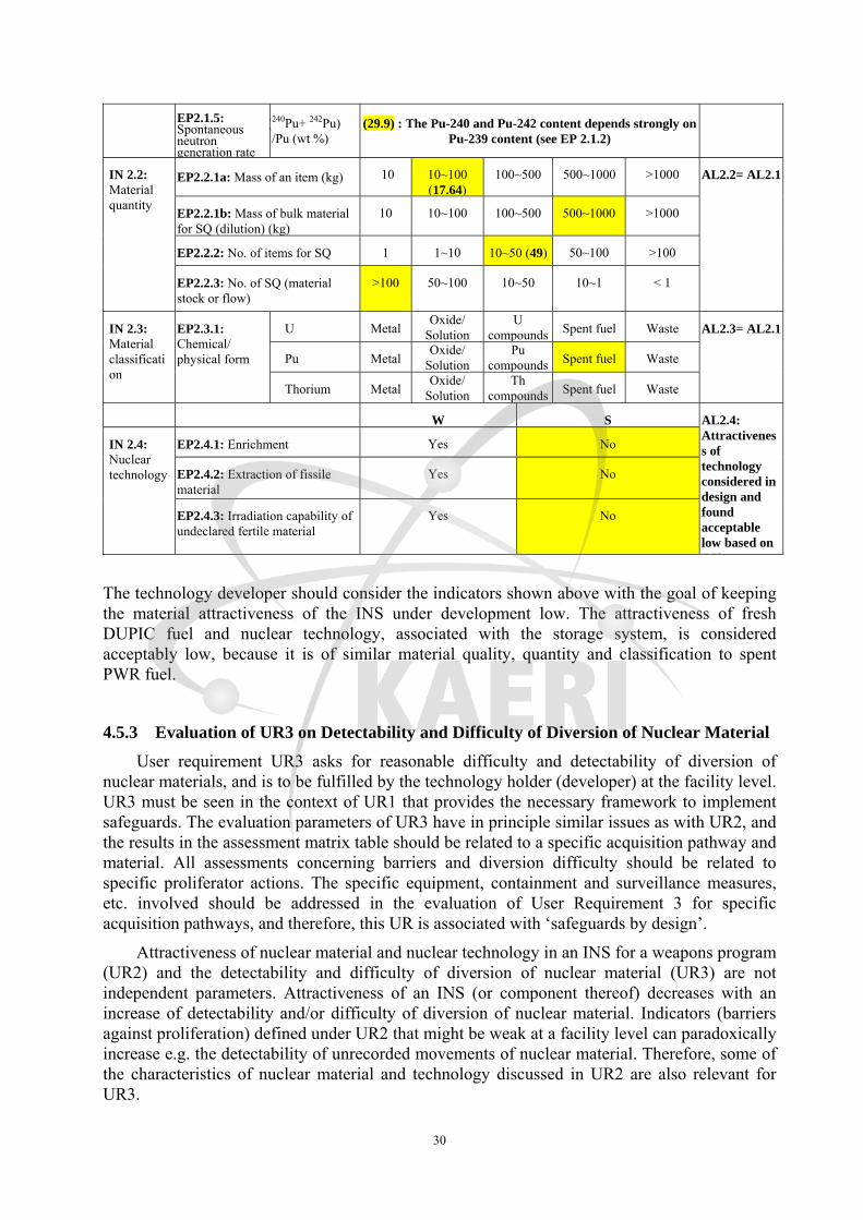
30
EP2.1.5: Spontaneous neutron generation rate
(240Pu+ 242Pu) /Pu (wt %)
(29.9) : The Pu-240 and Pu-242 content depends strongly on Pu-239 content (see EP 2.1.2)
IN 2.2: Material quantity
EP2.2.1a: Mass of an item (kg) 10 10~100 (17.64)
100~500 500~1000 >1000 AL2.2= AL2.1
EP2.2.1b: Mass of bulk material for SQ (dilution) (kg)
10 10~100 100~500 500~1000 >1000
EP2.2.2: No. of items for SQ 1 1~10 10~50 (49) 50~100 >100
EP2.2.3: No. of SQ (material stock or flow)
>100 50~100 10~50 10~1 < 1
IN 2.3: Material classification
EP2.3.1: Chemical/ physical form
U MetalOxide/
SolutionU
compounds Spent fuel Waste AL2.3= AL2.1
Pu MetalOxide/
SolutionPu
compounds Spent fuel Waste
Thorium MetalOxide/
SolutionTh
compounds Spent fuel Waste
W S AL2.4: Attractiveness of technology considered in design and found acceptable low based on EJ?
IN 2.4: Nuclear technology
EP2.4.1: Enrichment Yes No
EP2.4.2: Extraction of fissile material
Yes No
EP2.4.3: Irradiation capability of undeclared fertile material
Yes No
The technology developer should consider the indicators shown above with the goal of keeping the material attractiveness of the INS under development low. The attractiveness of fresh DUPIC fuel and nuclear technology, associated with the storage system, is considered acceptably low, because it is of similar material quality, quantity and classification to spent PWR fuel.
4.5.3 Evaluation of UR3 on Detectability and Difficulty of Diversion of Nuclear Material
User requirement UR3 asks for reasonable difficulty and detectability of diversion of nuclear materials, and is to be fulfilled by the technology holder (developer) at the facility level. UR3 must be seen in the context of UR1 that provides the necessary framework to implement safeguards. The evaluation parameters of UR3 have in principle similar issues as with UR2, and the results in the assessment matrix table should be related to a specific acquisition pathway and material. All assessments concerning barriers and diversion difficulty should be related to specific proliferator actions. The specific equipment, containment and surveillance measures, etc. involved should be addressed in the evaluation of User Requirement 3 for specific acquisition pathways, and therefore, this UR is associated with ‘safeguards by design’.
Attractiveness of nuclear material and nuclear technology in an INS for a weapons program (UR2) and the detectability and difficulty of diversion of nuclear material (UR3) are not independent parameters. Attractiveness of an INS (or component thereof) decreases with an increase of detectability and/or difficulty of diversion of nuclear material. Indicators (barriers against proliferation) defined under UR2 that might be weak at a facility level can paradoxically increase e.g. the detectability of unrecorded movements of nuclear material. Therefore, some of the characteristics of nuclear material and technology discussed in UR2 are also relevant for UR3.

31
Based on the above analysis, the proliferation resistance indicators and evaluation parameters in User Requirement 3 for the specific acquisition/diversion pathway of the fresh DUPIC fuel from the storage bay are rationalized as follows:
1) Indicator 2.1 on accountability:
A. For the verification of the status of the material accounting data, the IAEA must be able to derive a statement of Material Unaccounted For (MUF), and a statistical Limit of Error for the MUF (LEMUF).
B. However, there is no MUF for fresh DUPIC fuel bundles because the inspector measurement capability for fresh DUPIC fuel bundles in the storage pool is mainly item counting complemented with a passive NDA method, i.e., the physical inventory of fresh DUPIC fuel bundles in the storage is verified using item counting and NDA based on the sample size and sampling plan.
2) Indicator 3.2 on amenability for C/S +and monitoring systems:
A. This indicator considers the related evaluation parameters to monitor the nuclear material movement, and requires detailed acquisition pathway analysis for the installation of containment and surveillance (C/S) measures.
B. The use of C/S measures is aimed at verifying information on the movement of nuclear or other materials, equipment and samples, or preservation of the integrity of safeguards-relevant data. In many instances, C/S measure covers the period when the inspector is absent, thus ensuring the continuity of knowledge for the IAEA and contributing to the cost effectiveness.
C. The collected C/S data from the system can be verified using the review software review program against the inventory change record (ICR).
D. In case of the fresh DUPIC fuel storage bay, the underwater radiation monitoring system can be installed to check the movement of fresh DUPIC fuel.
3) Indicator 3.3 on detectability of nuclear material:
A. This indicator is evaluated by the nature of the detection system and the nuclear material to be detected.
B. The evaluation parameters of the detectability include the possibility to identify nuclear material by NDA, the hardness of radiation signature and the need for passive/active mode.
4) Indicator 3.4 on difficulty to modify the process:
A. The difficulty of modifying the process depends on the complexity of the modification, cost for the process modification, safety implication of such a modification, and the time required to perform the relevant modification.
B. There are four categories of evaluation parameters regarding the difficulty to modify the process as shown in Table 16.
5) Indicator 3.5 on difficulty to modify facility design:
A. The difficulty of modifying a fuel cycle facility depends on the complexity of the modification, cost for the process modification, safety implication of such a modification, and the time required to perform the relevant modification, and the ease with which inspectors can detect such modifications.
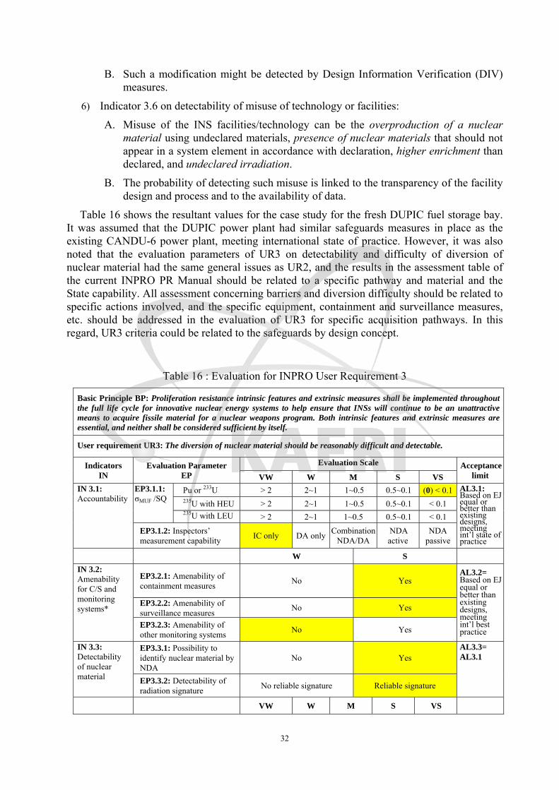
32
B. Such a modification might be detected by Design Information Verification (DIV) measures.
6) Indicator 3.6 on detectability of misuse of technology or facilities:
A. Misuse of the INS facilities/technology can be the overproduction of a nuclear material using undeclared materials, presence of nuclear materials that should not appear in a system element in accordance with declaration, higher enrichment than declared, and undeclared irradiation.
B. The probability of detecting such misuse is linked to the transparency of the facility design and process and to the availability of data.
Table 16 shows the resultant values for the case study for the fresh DUPIC fuel storage bay. It was assumed that the DUPIC power plant had similar safeguards measures in place as the existing CANDU-6 power plant, meeting international state of practice. However, it was also noted that the evaluation parameters of UR3 on detectability and difficulty of diversion of nuclear material had the same general issues as UR2, and the results in the assessment table of the current INPRO PR Manual should be related to a specific pathway and material and the State capability. All assessment concerning barriers and diversion difficulty should be related to specific actions involved, and the specific equipment, containment and surveillance measures, etc. should be addressed in the evaluation of UR3 for specific acquisition pathways. In this regard, UR3 criteria could be related to the safeguards by design concept.
Table 16 : Evaluation for INPRO User Requirement 3
Basic Principle BP: Proliferation resistance intrinsic features and extrinsic measures shall be implemented throughout the full life cycle for innovative nuclear energy systems to help ensure that INSs will continue to be an unattractive means to acquire fissile material for a nuclear weapons program. Both intrinsic features and extrinsic measures are essential, and neither shall be considered sufficient by itself.
User requirement UR3: The diversion of nuclear material should be reasonably difficult and detectable.
Indicators IN
Evaluation Parameter EP
Evaluation Scale Acceptance limit VW W M S VS
IN 3.1: Accountability
EP3.1.1: σMUF /SQ
Pu or 233U > 2 2~1 1~0.5 0.5~0.1 (0) < 0.1 AL3.1: Based on EJ equal or better than existing designs, meeting int’l state of practice
235U with HEU > 2 2~1 1~0.5 0.5~0.1 < 0.1 235U with LEU > 2 2~1 1~0.5 0.5~0.1 < 0.1
EP3.1.2: Inspectors’ measurement capability IC only DA only Combination
NDA/DANDA active
NDA passive
W S
IN 3.2: Amenability for C/S and monitoring systems*
EP3.2.1: Amenability of containment measures No Yes
AL3.2= Based on EJ equal or better than existing designs, meeting int’l best practice
EP3.2.2: Amenability of surveillance measures No Yes
EP3.2.3: Amenability of other monitoring systems No Yes
IN 3.3: Detectability of nuclear material
EP3.3.1: Possibility to identify nuclear material by NDA
No Yes AL3.3= AL3.1
EP3.3.2: Detectability of radiation signature No reliable signature Reliable signature
VW W M S VS

33
IN 3.4: Difficulty to modify the process
EP3.4.1: Extent of automation N/A Manual
operation N/A Partial automation
Full automation
AL3.4= AL3.2
EP3.4.2: Availability of data for inspectors
Operators data available from
his records ** ** ** NRTA
active
W S EP3.4.3: Transparency of process
No Yes
EP3.4.4: Accessibility of material to inspectors No Yes
IN 3.5: Difficulty to modify facility design
EP3.4.4: Verifiability of facility design by inspectors***
No Yes
AL3.5= AL3.2
IN 3.6: Detectability of misuse of technology or facilities.
EP3.5.1: Possibility to detect misuse of the technologies and the INS facilities for processing of undeclared nuclear materials.
No Yes
AL3.6= AL3.2
* Evaluation of this indicator requires detailed acquisition pathway analysis first; it is related to system elements rather than to facilities within an INS.
** Detailed scale is illustrative only, and subject to further considerations. This parameter may include standard operator reporting information flow and NRTA.
*** This parameter is linked to the transparency of design and depends on the willingness of the operator/state to demonstrate its level of transparency.
The technology developer should consider the indicators shown above with the goal of keeping the detectability and difficulty of diversion equal to or better than existing designs. For this case study, it can be concluded that the diversion of fresh DUPIC fuel through the selected pathway from the fresh DUPIC fuel bay is reasonably difficult and detectable by applying the safeguards tools and measures of the CANDU-6 power plant.
4.6 Evaluation of UR4 on Multiplicity and Robustness of Barriers at each Segment of the
Diversion Pathway
User requirement 4 (UR4) asks for innovative nuclear energy systems to incorporate multiple proliferation resistance features and measures, which is to be fulfilled by the technology developers in cooperation with a PR expert. INPRO has defined two criteria for user requirement UR4: multiplicity (defense in depth) and robustness of barriers.
UR4 can be assessed at the State level, the INS level, and the facility level including facility specific pathways, although different issues are involved. Some of the characteristics of nuclear material and technology discussed in UR2 and detectability and difficulty of diversion in UR3 are integral elements in assessing UR4. In addition, it must be noted that UR1 provides a State-level barrier against proliferation, the necessary legal framework for implementing safeguards, and in this context the evaluation of UR3. The multiplicity of proliferation barriers should be considered together with their robustness in assessing UR4. Accordingly, the concern is how to demonstrate the “robustness” of barriers and how to relate this to State capabilities.
4.6.1 Evaluation of Multiplicity of Proliferation Barriers
Table 17 shows proliferation barriers identified at each segment of the acquisition/diversion of fresh DUPIC fuel from the DUPIC power plant using UR1, UR2 and UR3.
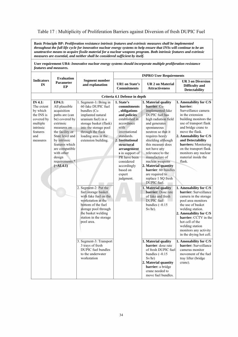
34
Table 17 : Multiplicity of Proliferation Barriers against Diversion of fresh DUPIC Fuel
Basic Principle BP: Proliferation resistance intrinsic features and extrinsic measures shall be implemented throughout the full life cycle for innovative nuclear energy systems to help ensure that INSs will continue to be an unattractive means to acquire fissile material for a nuclear weapons program. Both intrinsic features and extrinsic measures are essential, and neither shall be considered sufficient by itself.
User requirement UR4: Innovative nuclear energy systems should incorporate multiple proliferation resistance features and measures.
Indicators IN
Evaluation Parameter
EP
Segment number and explanation
INPRO User Requirements
UR1 on State’sCommitments
UR 2 on Material Attractiveness
UR 3 on Diversion Difficulty and Detectability
(S f d bili )Criteria 4.1 Defense in depth
IN 4.1: The extent by which the INS is covered by multiple intrinsic features and measures
EP4.1: All plausible acquisition paths are (can be) covered by extrinsic measures on the facility or State level and by intrinsic features which are compatible with other design requirements.* (=AL4.1)
1. Segment-1: Bring in 60 fake DUPIC fuel bundles (Cs-implanted natural uranium fuel) in a storage basket (flask) into the storage pool through the flask loading area in the extension building.
1. State’s commitments, obligations and policies established in accordance with international standards.
2. Institutional structural arrangements in support of PR have been considered accordingly based on expert judgment.
1. Material quality barrier: Cs-implemented fake DUPIC fuel has high radiation field and generates spontaneous neutron so that it requires heavy shielding although this measure does not have any relevance to the manufacture of nuclear weapons
2. Material quantity barrier: 60 bundles are required to replace 1 SQ fresh DUPIC fuel.
1. Amenability for C/S barrier: Surveillance camera in the extension building monitors the use of transport flask and bridge crane to move the flask.
2. Amenability for C/S and Detectability barriers: Monitoring on the transport flask monitors any nuclear material inside the flask.
2. Segment-2: Put the fuel storage basket with fake fuel on the workstation at the bottom of the fuel storage pool through the basket welding station in the storage pool area.
1. Material quality barrier: Dose rate of fake and fresh DUPIC fuel bundles (~0.15 Sv/hr).
1. Amenability for C/S barrier: Surveillance camera in the storage pool area monitors the use of basket welding station.
2. Amenability for C/S barrier: CCTV in the hot cell of the welding station monitors any activity in the drying hot cell.
3. Segment-3: Transport 3 trays of fresh DUPIC fuel bundles to the underwater workstation
1. Material quality barrier: dose rate of fresh DUPIC fuel bundles (~0.15 Sv/hr)
2. Material quantity barrier: a bridge crane needed to move fuel bundles.
1. Amenability for C/S barrier: Surveillance cameras monitor movement of the fuel tray lifter (bridge crane).

35
4. Segment-4: on the underwater workstation, replace the fake DUPIC fuel in the storage basket with the fresh DUPIC fuel bundles using a fuel lifting tool.
1. Material quality barrier: special equipment (fuel lifting tool) needed.
1. Amenability for C/S and detectability barriers: Surveillance cameras monitor the movement of fuels.
2. Amenability for C/S barrier: Surveillance cameras monitor the use of fuel lifting tool.
3. Detectability barrier: NDA equipment monitors the movement of fuel.
5. Segment-5: Transport 3 trays of fake DUPIC fuel bundles back to the fresh DUPIC fuel bay.
1. Material quality barrier: dose rate of fresh DUPIC fuel bundles (~0.15 Sv/hr)
2. Material quantity barrier: A bridge crane needed.
1. Amenability for C/S barrier: Surveillance cameras monitor movement of the fuel tray lifter.
6. Segment-6: Take the loaded storage basket from the pool area to the extension buildingthrough the basket welding station.
1. Material quality and quantity barriers: dose rate of fresh DUPIC fuel bundles (~0.15 Sv/hr) and 60 fuel bundles requires heavy shielded container
1. Amenability for C/S barrier: CCTV in the hot cell of the welding station monitors any basket movement in the drying hot cell.
2. Detectability barrier: Monitoring on the transport flask monitors any fuel basket in the flask.
3. Surveillance camera monitors movement of the transport flask.
7. Segment-7: Transport the loaded storage basket from the extension building to the outside parking lot using a heavy-duty truck
1. Material quantity barrier: The flask containing a storage basket loaded with fake DUPIC fuel requires a crane to transport.
2. Material quantity barrier: A heavy duty truck needs to be used.
1. Amenability for C/S barrier: Surveillance camera in the extension building monitors movement of a transport flask and a heavy duty truck.
The acceptance limit for the multiplicity requirement of UR4 is that all plausible acquisition/ diversion pathways of the INS (composed of several sequential segments) are or can be covered by extrinsic measures at the facility and/or State level and by intrinsic features compatible with other design requirements. The main purpose of this indicator is to encourage designers to incorporate intrinsic features in an INS in order to facilitate the implementation of safeguards, to decrease the impact of safeguards implementation on the facility, and to make the INS an unattractive means to acquire fissile material for a nuclear weapons program. Therefore, the assessment procedure and metrics to evaluate Indicator 4.1 on multiplicity of User Requirement 4 can be as follows:

36
1) Identify proliferation target materials and related plausible acquisition/diversion pathways in an INS using the INPRO approach for “acquisition/diversion pathway analysis” as shown in Figure 2 (A case study is shown in Section 3);
2) Carry out the detailed pathway analysis for the selected pathway from the plausible acquisition/diversion pathways (A case study is shown in Section 4.5);
3) In addition to the general tables necessary to perform the requirements by UR1, UR2 and UR3, identify intrinsic proliferation resistance features as well as extrinsic measures existing at each segment of the selected pathway, i.e., produce a table identifying proliferation barriers based on UR1, UR2 and UR3 for each of the plausible pathways (A case study is shown in Table 17);
4) Evaluate the multiplicity of barriers based on expert judgment concerning whether the selected acquisition pathway is (or can be) covered by extrinsic measures at the facility and/or State level and intrinsic features compatible with other design requirements. The scale for evaluating indicator 4.1 on multiplicity could be the same as in the current INPRO PR manual: W (weak) for ‘No multiple coverage’ and S (strong) for ‘Multiple coverage’ as shown in Table 18;
5) If the answer is W, then identify and incorporate additional intrinsic features and/or extrinsic measures to enhance the proliferation resistance with multiple coverage until the final answer is S; and
6) Repeat the above procedure for all the plausible acquisition pathways until the acceptance limit is met for each of the plausible acquisition/diversion pathways.
Table 18 : Evaluation Criteria for Multiplicity of Proliferation Barriers in UR4
Basic Principle BP: Proliferation resistance intrinsic features and extrinsic measures shall be implemented throughout the full life cycle for innovative nuclear energy systems to help ensure that INSs will continue to be an unattractive means to acquire fissile material for a nuclear weapons program. Both intrinsic features and extrinsic measures are essential, and neither shall be considered sufficient by itself.
User requirement UR4: Innovative nuclear energy systems should incorporate multiple proliferation resistance features and measures.
CR4.1 Defense in depth
Indicators IN
Evaluation Parameter EP
Evaluation Scale Acceptance limit
W S IN 4.1: The extent by which the INS is covered by multiple intrinsic features and measures
EP4.1: Analysis of each plausible acquisition pathway
Multiple coverage by extrinsic measures on the facility (UR3) and State level(UR1)
No Yes
AL4.1: Based on expert judgment all plausible acquisition paths are (can be) covered by extrinsic measures on the facility and State level and by intrinsic features which are compatible with other design requirements.
Multiple coverage by intrinsic features which are compatible with other design requirements (UR2)
No Yes

37
4.6.2 Evaluation of Robustness of Proliferation Barriers
The robustness of proliferation barriers in the context of INPRO PR methodology describes the effectiveness of acquisition pathway barriers. These are a measure of the difficulty to defeat proliferation barriers in terms of time and efforts. Robustness is not a function of the number of barriers, or of their individual characteristics, but is an integrated value of the whole. For example, the difficulty in material handling, if not supplemented by safeguards measures, would have a very minor effect to the State level diversion compared to the diversion difficulty and detectability barriers.
A State proliferator would have unrestricted access to the entire nuclear facility and the equipment designed for handling nuclear materials. Therefore, the robustness of proliferation barriers is defined in PRADA as a combination of the barriers described in UR1, UR2 and UR3, and is measured by determining whether the Safeguards Goals can be met. However, it should not be construed as implying that proliferation using a system and its materials for which the safeguards goals can be met is impossible (i.e., the system is proliferation-proof).
The diversion difficulty and detectability required in UR3 (safeguardability) is based on the effectiveness and efficiency (timeliness) of the IAEA safeguards system framework established under UR1. Successful evaluation of the robustness of barriers identified in UR4 requires sufficient information on the process and design information of the INS, which will only become available for an INS as the design of an INS progresses. Based on the above rationale, the proposed approach to evaluate Indicator 4.2 concerning the robustness of proliferation barriers along the plausible acquisition/diversion pathway is:
1) Evaluate the effectiveness of each of proliferation barriers identified by Criteria 4.1 on multiplicity for each segment of the selected plausible pathway;
2) Evaluate the robustness of multiple barriers along the selected pathway based on expert judgment if robustness of the barriers would be sufficient to meet the IAEA Safeguards Goals. The scale for evaluating indicator 4.2 on robustness could be: W (weak) for ‘No (Safeguards goals cannot be met)’ and S (strong) for ‘Yes (Safeguards goals can be met)’ as shown in Table 19;
3) If the answer is W, then identify and incorporate additional intrinsic features and/or extrinsic measures to provide or improve the proliferation resistance until the final answer is S.
4) Repeat the above procedure for all the other plausible acquisition pathways until the acceptance limit is met for each of the plausible pathways.
Table 19 : Evaluation Criteria for Robustness of Proliferation Barriers in UR4
Basic Principle BP: Proliferation resistance intrinsic features and extrinsic measures shall be implemented throughout the full life cycle for innovative nuclear energy systems to help ensure that INSs will continue to be an unattractive means to acquire fissile material for a nuclear weapons program. Both intrinsic features and extrinsic measures are essential, and neither shall be considered sufficient by itself.
User requirement UR4: Innovative nuclear energy systems should incorporate multiple proliferation resistance features and measures.
CR4.2 Robustness of barriers
Indicators Evaluation Parameter Evaluation Scale Acceptance

38
IN EP W S limit
IN4.2: Robustness of barriers covering each acquisition path
EP4.2: IAEA safeguards goals (time and quantity) can be met
No Yes
AL4.2: Robustness is sufficient based on expert judgment
4.7 Evaluation of User Requirement 5 on Optimization of Design
The cost of incorporating additional intrinsic features and extrinsic measures into an INS that are required by UR4 to provide or improve proliferation resistance could be excessively high. Therefore, UR4 leads to User Requirement 5, optimization of the combination of intrinsic features and extrinsic measures in the design/engineering phase to provide cost-efficient proliferation resistance.
The main concern in UR4 is to demonstrate the “robustness” of barriers and relate this to the state capability through the optimization of the robustness of proliferation. Therefore, the assessment procedure and metrics to evaluate UR5, optimization of combination of PR features and measures, would be follows:
1) Evaluate whether PR has been taken into account as early as possible in the design and development of the INS;
2) Optimize costs of the combination of intrinsic features and extrinsic measures which are to be incorporated to provide or improve proliferation resistance and to support the implementation of safeguards;
3) Confirm whether a verification approach with a level of extrinsic measures can be designed and agreed between the verification authority and the State.

39
5. Interactions with the Proliferation Resistance & Physical Protection Working Group (PRPPWG) of Generation IV International Forum (GIF) The GIF PR&PP9 and INPRO PR methodologies developed by international teams are the
two most widely accepted methodologies, and the necessity to harmonize the two methodologies has been acknowledged by the technology developers and potential users of the methodologies10. The GIF PR&PP methodology considers a nuclear energy system primarily from the standpoint of the designer of the system and identifies specific proliferation challenges, system responses, and outcomes, while the INPRO methodology looks primarily from the standpoint of nuclear energy system users. Both approaches endorse the need for proliferation resistance considerations to be taken into account as early as possible in the design and development of a nuclear energy system. Figure 13 shows the interaction between the INPRO and GIF proliferation resistance methodologies.
State RequirementsSystem Requirements
System Design
Who wantsto know?
INPROASSESSMENT
INPRO PR APPROACH GIF PRPP APPROACHUR4 (Multiplicity of Barriers)
PRPPEVALUATIONcommon elements
1. Basic principle2. User requirements: (UR1 – 5)3. Indicators4 Assessment: evaluation parameters
1. Technology goals2. Measures3. Metrics4. Evaluation: challenge response outcomes
Acquisition Pathway Analysis ( obustness?indicator)뱑
PRcceptable?밃
Technology holders (designers)
Technology users (States, utilities)
YES
NO
END
INTERACTION OF INPRO AND GIF PROLIFERATION
RESISTANCE APPROACHES
Figure 13 : Interaction of INPRO and GIF Proliferation Resistance Methodologies
9 Generation IV International Forum PR&PP Expert Group, Evaluation Methodology for Proliferation Resistance and Physical Protection of Generation IV Nuclear Energy Systems, Revision 5, GIF/PRPPEG/2006/005, September 30, 2006. 10 George Pomeroy, et al., Approaches to Evaluation of Proliferation Resistance of Nuclear energy Systems, Proceedings of INMM 49th Annual Meeting, Nashville, TN (2008).
40
Both methodologies share certain similarities, beginning with a common definition of proliferation resistance, and have a hierarchical analytical structure, with proliferation resistance principles, high-level evaluation factors and multiple measures or requirements related to each high-level factor. Both methodologies incorporate institutional and policy context for the system under consideration. INPRO takes into account a State’s non-proliferation commitments and agreements in one of its User Requirements. In the GIF approach, however, these commitments are treated implicitly when estimating the GIF detection probability measure. The GIF methodology lends itself to comparing the proliferation resistance of alternative nuclear energy systems. GIF separates a system into components (system elements) and performs a pathway analysis, providing the basis for a proliferation resistance evaluation. Neither approach aggregates results into a single numerical value or grade, so that strengths and weaknesses under each of the main evaluation criteria are explicitly considered.
There are several notable differences between the two methodologies. The INPRO approach focuses on the proliferation resistance of a declared, safeguarded nuclear energy system in a specific State, and explicitly excludes the analysis of clandestine facilities, including those that might be needed to complete a proliferation pathway or breakout scenario in which a facility is overtly misused for proliferation purposes. The GIF PR&PP methodology considers both declared and undeclared facilities and activities, as well as misuse following breakout, to complete the proliferation pathway from acquisition and processing of material to fabrication of a nuclear explosive device. INPRO examines the whole system, sets explicit User Requirements, and asks how the system meets these User Requirements.
Interaction between the Generation IV International Forum (GIF) and INPRO methodologies is intended to identify common metrics (GIF) and evaluation parameters (INPRO) to be used in both methodologies to determine the proliferation resistance of a nuclear energy system as part of a proliferation pathway. Both approaches recognize the concept of barriers to proliferation, but implement the concept differently. Figure 14 shows the comparison of metrics and evaluation parameters used in the GIF and INPRO PR evaluation methodologies, respectively.
Both methodologies recognize that the degree of proliferation resistance results from a combination of, inter alia, technical design features, operational modalities, institutional arrangements and safeguards measures3, and treat proliferation resistance as a function of extrinsic measures (e.g., safeguards, etc.) and intrinsic features (e.g., material attractiveness, etc.). In particular, effective international safeguards are an essential component of proliferation resistance, and proliferation resistance should not be viewed as a substitute for the highest standards of international safeguards, or for other non-proliferation tools such as effective export controls.
In the INPRO methodology, the robustness of proliferation barriers is the effectiveness of acquisition pathway barriers, and is a combination of (a) safeguardability (UR-3) augmented by sufficient safeguards to achieve the IAEA’s safeguards goals, and (b) technical difficulty based on low attractiveness of material and technology (UR-2). “Technical difficulty” consists of two parts: first, the utility for use in nuclear explosives after any required conversion, and secondly, the difficulty of material handling and the availability and difficulty of different processes needed to produce weapons-usable material after diversion/misuse.
The technical difficulty of barriers descried in the GIF PR&PP approach under “Technical Difficulty” (Figure 14) represents the probability of failing to achieve the proliferation goal. This evaluation will be subject to expert judgment, as determined by following GIF PR&PP evaluation methodology. As described in the previous section, the INPRO assessment

41
methodology needs information from the results of such analyses, performed jointly by a technology developer (supplier), safeguards experts, and experts in PR. These analyses can be done by the GIF PR methodology analyzing the “system response to challenges”.
In the GIF PR&PP methodology, a pathway analysis is performed to identify acquisition scenarios that a State could pursue to obtain nuclear weapons by taking advantage of its peaceful nuclear materials and facilities. In order to develop the appropriate methods to evaluate the multiplicity and robustness of proliferation barriers for INPRO, the GIF pathway concept has been applied to the DUPIC fuel cycle to identify and analyze the acquisition/diversion pathway for nuclear materials. This demonstrates the possibility of merging both methodologies to one holistic approach.
Strategy (GIF):Concealed Diversion – Concealed Misuse – Clandestine Facilities UseSystem Response
INPRO:Possible Contribution of the Declared Fuel Cycleto a Nuclear Weapons Programme
Threat Space – State Capabilities, Goals뭩
Plausible Acquisition PathDeclared & Undeclared Facilities
Fissile Material Type(Material available in the
Fuel cycle)
Proliferation Technical Difficulty
Proliferation Costs Proliferation Time
Detection Probability / Safeguardability(Declared Facilities)
Detection Probability (Undeclared Facility)
Detection Resource Efficiency(Detection Costs)
Optimization of Design- Minimal total costs of intrinsic features and extrinsic Measures (Cost Analysis!)
INPRO UR/Indicators/Evaluation Parameter
Attractiveness of NM and Technology- Isotopic Composition- Chemical / Physical Form. etc- Nuclear Technology
Reasonable Acquisition Paths covered by multiple PR Features and Measures- Extent/Robustness
State Commitments including institutional structuralArrangements (e.g. MNA) regarding non-proliferation
Difficulty and detectability of diversion of NM(Safeguardability)
Figure 14 : Dependencies of Measures in the GIF PR Evaluation Methodology and their Relation to INPRO User Requirements/Indicators
42
6. Summary / Conclusions The objective of PRADA is to further develop a documented approach for performing
proliferation assessments using the INPRO methodology and, where appropriate, the GIF PR methodology. In this context, a systematic approach for the identification and analysis of acquisition/diversion pathways of nuclear materials has been developed and applied to the DUPIC fuel cycle system. Procedures for determining and analyzing plausible acquisition pathways have been developed and tested in detail for an acquisition pathway at the facility level.
Multiplicity of barriers was demonstrated using a proliferation barrier analysis. It was shown that barriers against proliferation resistance specified in UR1, UR2, and UR3 are not independent and that in addition the strength of barriers against proliferation might depend on state capabilities.
The degree of proliferation resistance results from a combination of, inter alia, technical design features, operational modalities, institutional arrangements and safeguards measures [3]. The effectiveness of barriers to proliferation can be categorized as: (1) technical difficulty in making weapons (as a state level concern, not related to a specific facility), (2) barriers representing the difficulty in handling and processing materials (both at the State and at the facility level): (3) barriers leading to difficulty/detectability and safeguardability (at a specific facility related pathway level). Therefore, there are three levels of proliferation resistance indicators in the INPRO PR assessment: State level, INS level and facility-level including facility specific pathways.
The fulfillment of User Requirement 1 (UR1) “States’ commitments, obligations and policies regarding non-proliferation and its implementation” has considerable impact on proliferation resistance of an INS. It demonstrates on one hand States’ compliance with non-proliferation commitments, and on the other hand establishes the tools to detect non compliance at the State and INS/Facility levels. It has two criteria (CR): legal framework (CR1.1) and institutional structural arrangements (CR1.2) at the State level. CR1.1 asks the State to establish a sufficient legal framework addressing international non-proliferation, i.e., ensuring the adequacy of the States’ commitment, obligations and policies regarding non-proliferation, and CR1.2 determines if the implementation is adequate to fulfill international standards in the non-proliferation regime. It also addresses the capability of the IAEA to detect undeclared nuclear materials and activities
User Requirement 2 states that the INS should have low attractiveness of nuclear material and technology for use in a nuclear weapons program. This user requirement refers to key proliferation barriers related to material and technology characteristics at the facility level. The role of the INPRO assessor is to determine whether an INS has achieved a level of attractiveness that is acceptably low by assessing the corresponding criteria. The attractiveness of nuclear material is determined by two intrinsic features, the conversion time and the total mass needed to achieve one significant quantity. The attractiveness of nuclear material increases with shorter conversion time of the acquired material and by smaller mass of nuclear material needed to form one significant quantity.
Currently UR2 results in a table that describes all the proliferation target materials in the system, but not a specific proliferation target material for specific pathways. The assessment table should provide a means for identifying the target being described in a pathway, and therefore an additional column could be added: “Not applicable to the pathway or level of assessment”. The proliferator’s strategy will determine the level of detail. Therefore, the tables

43
should reflect the impact of State capabilities on the strength of proliferation barriers to address the different assessment levels. The table should be self-documenting. It should be noted that this process could be performed at higher level in the early design phases, with updates as the design matures.
User requirement UR3 asks for reasonable difficulty and detectability of diversion of nuclear materials, and is to be fulfilled by the technology holder (developer) at the facility level. UR3 must be seen in the context of UR1 that provides the necessary framework to implement safeguards. The evaluation parameters of UR3 have in principle similar issues as with UR2, and the results in the assessment matrix table should be related to a specific acquisition pathway and material. All assessments concerning barriers and diversion difficulty should be related to specific proliferator actions. The specific equipment, containment and surveillance measures, etc. involved should be addressed in the evaluation of User Requirement 3 for specific acquisition pathways, and therefore, this UR is associated with ‘safeguards by design’.
Attractiveness of nuclear material and nuclear technology in an INS for a weapons program (UR2) and the detectability and difficulty of diversion of nuclear material (UR3) are not independent parameters. Attractiveness of an INS (or component thereof) decreases with an increase of detectability and/or difficulty of diversion of nuclear material. Indicators (barriers against proliferation) defined under UR2 that might be weak at a facility level can paradoxically increase e.g. the detectability of unrecorded movements of nuclear material. Therefore, some of the characteristics of nuclear material and technology discussed in UR2 are also relevant for UR3.
It was shown that robustness is not a function of the number of barriers or of their individual characteristics but is an integrated function of the whole. UR4 evaluates the multiplicity and robustness of barriers and is correlated with UR5 concerning the cost and optimization of PR features and measures. The robustness of proliferation barriers as defined in PRADA is measured by determining whether the safeguards goals can be met. This does not imply that proliferation using an INS and its materials that meets safeguards goals is impossible (i.e. that the system is proliferation proof).
This leads to the question, why encourage States, designers and operators to make nuclear materials and technologies reasonably unattractive, if the value of proliferation resistance is determined by the capability to meet the safeguards goals? The INPRO Proliferation Resistance Basic Principle states in part: “Proliferation resistance intrinsic features and extrinsic measures shall be implemented…. to help ensure that INSs will continue to be an unattractive means to acquire fissile material for a nuclear weapons program…”1. Whether or not an INS is an “unattractive means” depends basically on the “risk of early detection”, on proliferation cost and proliferation time.
The INPRO assessment methodology needs information from the results of more quantitative analyses performed jointly by a technology developer (supplier), safeguards experts, and experts in PR. Such analyses are done by the GIF PR methodology when analyzing the “system response to challenges”. Accordingly, the GIF pathway concept was applied to the DUPIC fuel cycle to identify and analyze nuclear material acquisition/diversion pathways to evaluate the multiplicity and robustness of proliferation barriers. This demonstrates the possibility of merging both methodologies to one holistic approach.

44
REFERENCES
[1] International Atomic Energy Agency, Guidance for the Application of an Assessment Methodology for Innovative Nuclear Energy Systems, INPRO Manual – Proliferation Resistance, Volume 5 of the Final Report of Phase 1 of the International Project on Innovative Nuclear Reactors and Fuel Cycles(INPRO), IAEA-TECDOC-1575, IAEA Vienna (2007).
[2] International Atomic Energy Agency, “Terms of Reference for the INPRO Collaboration Project, Proliferation Resistance: Acquisition/Diversion Pathway Analysis,” IAEA, Vienna (5 May 2008).
[3] International Atomic Energy Agency, Proliferation Resistance Fundamentals for Future Nuclear Energy Systems, IAEA STR-332, IAEA Department of Safeguards, IAEA, Vienna (2002).
[4] W.I. Ko, H.B. Choi, and M.S. Yang, Cost Evaluation of a Commercial-Scale DUPIC Fuel Fabrication Facility (Part II) – Preliminary Conceptual Design, KAERI/TR-1373/99 (Rev.1), Korea Atomic Energy Research Institute (2005).
[5] International Atomic Energy Agency, The Structure and Content of Agreements between the Agency and States required in connection with the Treaty on the Non-proliferation of Nuclear Weapons, INFCIRC/153 (Corrected), June 1972
[6] International Energy Agency, Model Protocol Additional to the Agreement(s) between States and the International Atomic Energy Agency for the Application of Safeguards, INFCIRC/540 (Corrected), Vienna, September 1997.
[7] International Atomic Energy Agency, Design Measures to Facilitate Implementation of Safeguards at Future Water Cooled Nuclear Power Plants, TRS-392, IAEA, Vienna (1998).
[8] International Atomic Energy Agency, IAEA Safeguards Glossary 2001 Edition, International Nuclear Verification Series No.3, IAEA, Vienna (June 2002).
[9] Generation IV International Forum PR&PP Expert Group, Evaluation Methodology for Proliferation Resistance and Physical Protection of Generation IV Nuclear Energy Systems, Revision 5, GIF/PRPPEG/2006/005, September 30, 2006.
[10] George Pomeroy, et al., Approaches to Evaluation of Proliferation Resistance of Nuclear energy Systems, Proceedings of INMM 49th Annual Meeting, Nashville, TN (2008).