A STUDY ON SINGLE-LAP NOTCHED WOVEN KENAF … · FEA modelling 102 5.5 Concluding ... investigated...
51
A STUDY ON SINGLE-LAP NOTCHED WOVEN KENAF REINFORCED POLYMER BOLTED JOINT UNDER TEMPERATURE ACTION ANDERS HANS ANAK ROMAYNE A thesis submitted in fulfilment of the requirement for the award of the Degree of Master of Civil Engineering Faculty of Civil and Environmental Engineering Universiti Tun Hussien Onn Malaysia NOVEMBER 2016
Transcript of A STUDY ON SINGLE-LAP NOTCHED WOVEN KENAF … · FEA modelling 102 5.5 Concluding ... investigated...
A STUDY ON SINGLE-LAP NOTCHED WOVEN KENAF REINFORCED
POLYMER BOLTED JOINT UNDER TEMPERATURE ACTION
ANDERS HANS ANAK ROMAYNE
A thesis submitted in fulfilment
of the requirement for the award of the
Degree of Master of Civil Engineering
Faculty of Civil and Environmental Engineering
Universiti Tun Hussien Onn Malaysia
NOVEMBER 2016

iii
DEDICATION
For my beloved mother and father, brother and sisters, uncles and aunties, my entire
cousins and my friends, thank you for continue support me to achieve my scroll and
our happiness.

iv
ACKNOWLEDGEMENTS
This Master thesis would not be reality without the guidance of my main supervisor,
Dr. Hilton @ Mohd Hilton Bin Ahmad. His patience and dedication in guidance me
through the problems arising during the process of learning in this project are much
appreciated. I would like to extend my gratitude to my co-supervior, Dr. Haris Ahmad
Bin Israr Ahmad for his advice and moral support.
To all my friends from UTHM and my colleague also not forget my hometown friends,
your assistance and moral support whenever I need are much appreciated.
Last but not least, I would like to acknowledge my employer, Universiti Tun Hussien
Onn Malaysia (UTHM) for offering me scholarship to continue my dream to pursue
Master study.
v
ABSTRACT
Study on natural fibers as reinforcing fibers in composite materials has started to gain
interest as engineering materials due to renewability and excellent specific strength.
Bolted joints requires introduction of hole that susceptible to stress concentration that
leads to strength reduction, more complex when exposed to elevated temperature.
Strength prediction tools are still lacking, limited success was found in semi-empirical
and numerical approach. More recently, extended finite element method (XFEM)
formulation has been reported in the literatures but there is no work has been carried
out to incorporate the strength prediction exposed to elevated temperature. Present
work predicted the notched strength and bearing stress at failures in open-hole and
single-lap bolted joints woven fabric kenaf composite coupons respectively using
XFEM by implementing traction-separation relationship. Strength prediction work of
2-D open hole and 3-D bolted joint models were then validated against experimental
datasets tested under room and elevated temperatures as specified in the testing series.
Research work concentrates on opening mode (Mode I) fracture associated with stress
raisers ahead of notch tip. The experimental results showed increasing trend of notched
strength and bearing stress under elevated temperature (120℃) due to matrix
toughening. XFEM results were in good agreement with experimental datasets results
where discrepancy less than 20% in notched coupon and within 8 – 35 % in bolted
joint, better strength predictions were found in thicker and cross-ply coupons. It was
found that XFEM techniques implemented able to predict the notched strength and
bearing stress at failure by using thermal coefficient and specified temperature under
elevated temperature with reasonable precision.
vi
ABSTRAK
Kajian gentian asli sebagai tetulang gentian dalam bahan komposit telah menarik
minat sebagai bahan kejuruteraan disebabkan mampu diperbaharui dan kekuatan
spesifik yang cemerlang. Sambungan bolt memerlukan penebukan lubang yang
cenderung kepada tegasan tumpuan yang menjurus kepada pengurangan kekuatan, dan
lebih kompleks jika terdedah pada suhu tinggi. Kaedah untuk meramal kekuatan masih
berkurangan, oleh itu penemuan yang terhad dilaporkan dalam analitikal dan
numerikal. Kajian terbaru dalam kaedah unsur terhingga lanjutan (XFEM) telah
dilaporkan tetapi masih belum ada kajian yang mengabungkan kekuatan komposit
yang terdedah kepada suhu tinggi. Kajian ini meramalkan kegagalan tegasan bukaan
dan tegasan galas masing-masing untuk kes plat bukaan dan sambungan bolt tindihan
tunggal komposit fabrik tenunan gentian kenaf mengunakan teknik XFEM yang
menghubungkan daya terikan-pemisahan. Kerja ramalan model 2-D untuk plat bukaan
dan model 3-D untuk sambungan bolt kemudiannya dibandingkan dengan data
eksperimen, di mana kedua-duanya diuji pada suhu bilik dan suhu tinggi seperti di
spesifikasikan dalam siri ujikaji. Kajian ini menumpukan kepada mod bukaan (Mod I)
yang berkaitan dengan pengumpulan tegasan di atas takuk bukaan. Keputusan
eksperimen memberikan trend peningkatan kekuatan bukaan plat dan kekuatan galas
di bawah suhu tinggi (120 ℃) disebabkan oleh pengukuhan matriks. Keputusan XFEM
menunjukkan perbandingan yang baik dengan set data eksperimen di mana
percanggahan diperolehi kurang daripada 20% dalam plat bukaan dan antara 8 - 35%
dalam siri sambungan bolt, ramalan yang lebih jitu diperolehi dalam plat yang tebal
dan “cross-ply”. Teknik XFEM yang dilaksanakan mampu untuk meramalkan
kekuatan bukaan plat dan tegasan galas pada kegagalan dengan mengambilkira pekali
suhu dan di bawah suhu tinggi dengan ketepatan yang munasabah.
vii
CONTENTS
TITLE i
DECLARATION ii
DEDICATION iii
ACKNOWLEDGEMENT iv
ABSTRACT v
ABSTRAK vi
CONTENTS vii
LIST OF TABLES x
LIST OF FIGURES xii
LIST OF SYMBOLS AND ABBREVIATIONS xvii
CHAPTER 1 INTRODUCTION 1
1.1 Background of study 1
1.2 Problem statements 3
1.3 Objectives 5
1.4 Scope of study 5
1.5 Organization of thesis 6
CHAPTER 2 LITERATURE REVIEW 8
2.1 Introduction 8
2.2 Natural fibers 9
2.2.1 Kenaf fibers 10
2.2.2 Characteristics and engineering properties of
kenaf fibers 12
2.3 Configuration of woven fabric fibers 14
2.4 Behaviour of composites subjected to elevated
temperatures 16
2.5 Open hole coupons 18
2.5.1 Experimental study on notched coupons 19
viii
2.5.1.1 Experimental study on notched
coupon under room temperature 19
2.5.1.2 Experimental study on notched coupon
subjected to elevated temperature 22
2.5.2 Strength prediction of notched coupons 23
2.5.2.1 Strength prediction by using analytical
approach 24
2.5.2.2 Strength prediction using numerical
simulations 26
2.6 Mechanical fastened composite joint 31
2.6.1 Failure modes in composites bolted joints 32
2.6.2 Experimental work of woven fabric
composites with bolted joints 33
2.6.3 Experimental with bolted joint with elevated
temperatures 35
2.6.3.1 Double-lap bolted joints 35
2.6.3.2 Single-lap bolted joints 36
2.6.4 Strength prediction of bolted joints using
analytical approach 37
2.6.5 Strength prediction of bolted joints using
numerical approach 38
2.6.5.1 Progressive damage modeling 38
2.6.5.2 Extended finite element method (XFEM) 41
2.7 Concluding remarks 44
CHAPTER 3 EXPERIMENTAL WORKS AND TWO-DIMENSIONAL
MODELING OF OPEN HOLE WOVEN FABRIC KENAF
COMPOSITE COUPON 46
3.1 Introduction 46
3.2 Experimental methodology 47
3.2.1 Materials preparations and matrix binders mixing 48
3.2.2 Fabrication of woven fabric kenaf composite
coupons 51
3.2.3 Panel cutting, drilling of circular hole and
mechanical testing 53
ix
3.2.4 Testing series 55
3.2.5 Determination of elastic and material properties 56
3.2.6 Determination of notched strength under
temperature condition. 57
3.3 XFEM modelling framework of notched
woven fabric kenaf composite 58
3.3.1 Meshing and boundary condition 58
3.3.2 Independently determined elastic and material
properties 61
3.3.3 Constitutive model used in XFEM modelling 63
3.4 Comparison of XFEM notched strength
prediction with experimental results 64
3.4.1 Benchmarking work of based on
Benoite et al., (2012) work 64
3.4.2 Strength prediction on notched woven
fabric kenaf composites under room
temperature 66
3.4.3 Strength prediction on notched woven
fabric kenaf composites under temperature 67
3.4.4 Typical load-displacement curve in XFEM
framework and associated damage plots 69
3.5 Concluding remarks 70
CHAPTER 4 EXPERIMENTAL METHODOLOGY AND RESULTS OF
SINGLE-LAP WOVEN FABRIC KENAF COMPOSITES 71
4.1 Introduction 71
4.2 Bolted joints configurations and mechanical testing 72
4.2.1 Testing coupons preparations 72
4.2.2 Bolted joints assembly configurations 73
4.2.3 Testing matrix 74
4.2.4 Preparation of bolted joint configurations
under elevated temperature exposure 75
4.2.5 Mechanical testing 76
4.3 Experimental results 77
4.3.1 Load-displacement behaviour 77
x
4.3.2 Bearing stress at failure as a function of W/d
and material type 80
4.3.3 Bearing stress at failure as a function of
coupon thickness and lay-up types 81
4.3.4 Bearing stress at failure as a function
of elevated temperature 83
4.3.5 Effect of secondary bending 84
4.4 Concluding remarks 86
CHAPTER 5 STRENGTH PREDICTION ON SINGLE-LAP BOLTED
JOINTS WOVEN FABRIC KENAF COMPOSITE USING
XFEM 87
5.1 Introduction 87
5.2 Pre-processing stage of FEA works 88
5.2.1 Modelling idealization and component assemblies 88
5.2.2 Element discretization 89
5.2.3 Elastic and material properties 90
5.2.4 Loading and boundary conditions 92
5.3 Modelling approaches and techniques 92
5.3.1 Application of bolt load 93
5.3.2 Contact interactions and friction coefficients 95
5.3.3 Implementation of constitutive modelling 96
5.3.4 Modelling under temperature condition 97
5.4 Strength prediction of woven fabric KFRP
single-lap joints 98
5.4.1 Mesh sensitivity and damage stabilization study 98
5.4.2 Typical load-displacement curve 100
5.4.3 Comparison of strength prediction with
FEA modelling 102
5.5 Concluding remarks 106
CHAPTER 6 CONCLUSIONS AND RECOMMENDATIONS 107
6.1 Conclusions 107
6.2 Recommendations for future works 108

xi
REFERENCE 109
APPENDIX A 116
APPENDIX B 117
APPENDIX C 121
x
LIST OF TABLES
TABLE TITLE PAGE
2.1 Comparison between natural and glass fibers
(Wambua et al., 2003)
10
2.2 Characteristic and properties of kenaf stems,
Malaysia (Abdul Khalid et al., 2010)
13
2.3 Mechanical properties of natural fibers
(Wambua et al., 2003)
13
2.4 Damage morphologies with different temperatures
17
2.5 Influence of severer conditions on tensile properties
- quasi isotropic laminates by Benoit et al., (2012)
22
2.6 Material degradation model in progressive damage
modeling approach purpose by Chang & Chang
(1987) and Tan (1991)
27
2.7 Influence of severe condition on strengths of bolted
joint (Benoit et al., 2012)
37
2.8 Hashin Failure criterion with failure mode
39
3.1 Laminate lay-up and designation
55
3.2 Material properties of open hole laminate woven
fabric kenaf composite
62
3.3 Material properties of carbon/epoxy from Benoit et
al., (2012), Ahmad (2012), and Santiuste et al.,
(2011) work.
65
3.4 Comparisons of experimental open hole strength
with current XFEM modeling and experimental
work by Benoit et al., (2012)
65
xi
3.5 Open hole strength of woven fabric kenaf composite
under room temperature
66
3.6 Open hole strength of woven fabric kenaf composite
under elevated temperature
68
4.1 Range of test parameters investigated for woven
KFRP single-lap Joints tests
75
4.2 Maximum bearing stress at failure in all testing lay-
up series under room temperature and elevated
81
5.1 Elastic properties of woven KFRP lay-ups
investigated in single-lap bolted joint of this study
90
5.2 Material properties implemented in physically-based
constitutive model
92
5.3 Comparison work of XFEM model with
experimental works in single-bolt joint woven fabric
kenaf composites
103
xii
LIST OF FIGURES
FIGURES TITLE PAGE
2.1 Kenaf plant and physical appearance of kenaf fiber
(Karnani, 1996)
11
2.2 Various type of woven fabric type
(Dixit & Harlal, 2013)
14
2.3 Plain Weave kenaf (a) top view (b) side cross-section
view (Salman et al., 2015)
15
2.4 Woven laminate staking sequence direction in quasi-
isotropic composite coupon
16
2.5 Variation of stiffness with temperature for a typical
polymer matrix material (Thoppul et al., 2009)
18
2.6 Coupon under a remote tensile stress, including the
stress distribution along the ligament
20
2.7 Damage zone in 8 layers weave with 2.5 mm hole
diameter (Manger, 1999)
21
2.8 Tensile vs open hole tensile test at both temperatures on
quasi-isotropic (a) C/PPS and (b) C/Epoxy by Benoit
and Lakhdar (2011)
23
2.9 Damage zone and equivalent crack at notch vicinity
(Backlund & Aronsson, 1986)
24
2.10 Cohesive Zone concept by Barenblatt and Dugdale
25
2.11 Normal and tangential coordinates for a smooth crack
29
2.12 XFEM enrichment strategy
29
xiii
2.13 Phantom Node Concept (a) before partition of crack
element (b) after partitioning of crack element to sub-
element
30
2.14 Types of mechanical lap joint in structural
(Benoit et al., 2009)
31
2.15 Geometry dimension in bolted joints
(Pisano & Fuschi, 2011)
32
2.16 Failure modes in mechanically fastened composite
joints
33
2.17 Damage zone in specimen of W/d=4 critical damage
zone leading to catastrophic failure (Kontolatis, 2000)
34
2.18 Observation of failure surface in (a) double-lap joint
and (b) single-lap joint
(Benoit et al., 2012)
35
2.19 Secondary bending associate with the load eccentricity
36
2.20 Characteristic Curve (Chang et al., 1982)
38
2.21 Step applied for temperature effect in FEM
(Santiuste et al., 2011)
40
2.22 XFEM region assign in woven fabric kenaf composite
coupon for single-lap joint.
41
2.23 Physically-based transition-separation relationship
implemented in XFEM
42
2.24 Meshing sensitivity effect of CFRP on strength
prediction result PQ4 layup diameter 5 mm with W/d=3
(Ahmad, 2012)
42
2.25 Damage stabilization coefficient used in joint strength
prediction (Ahmad, 2012)
43
3.1 Flowchart of current project framework
47
3.2 Process of coupons preparation
48
3.3 Handloom weaving machine used to produce kenaf
fabric fiber layer
49
3.4 Plain weave diagram
49
xiv
3.5 Kenaf fiber used in current work with 0.7 mm diameter
yarn size
49
3.6 Epoxy and hardener used in the study
50
3.7 Silicon spray at mould surface preventing composite
coupon sticking
51
3.8 Epoxy resin spreading on top of woven kenaf
52
3.9 Hydraulic compression molding machine
52
3.10 Panel cutting coupon using hand jig saw
53
3.11 Hole drilling on coupon KWRP
54
3.12 Geometry of notched composite coupon
54
3.13 Range of tests carried out on PX1 and all other lay-ups
conducted under room and elevated temperatures
56
3.14 Drying oven used in the current study
58
3.15 Open hole composite coupon geometry for FEA model
59
3.16 Open hole meshing and XFEM assigned
59
3.17 Mesh sensitivity study effect strength prediction open
hole problem PX2-2.5 mm under room temperature
60
3.18 Boundary condition open hole woven KFRP
60
3.19 Damage stabilization study of open hole problem
RTPX2-2.5 mm
61
3.20 Graph for compliance against crack length for PX1
63
3.21 Traction-separation constitutive material law
63
3.22 Typical load-displacement curve PQ4 notched under
room temperature testing series implementing XFEM
technique.
69
3.23 Damage plot for at Point A, B, C and D of PQ4 open
hole model as labeled in Figure 3.21
70
4.1 Geometrical dimensions of composite coupons in
bolted joints
73
4.2 Schematic of single-lap joint configuration used in
present study
74
4.3 Range of tests carried out on PX2 and all lay-up
75
4.4 Universal testing machine Instron 3369
77
xv
4.5 Load displacement curve profile for room temperature
PX4 lay-up W/d=2 under finger-tight bolt load
78
4.6 Load displacement curve profile for room temperature
PX4 lay-up W/d=5 under finger-tight bolt load
78
4.7 Plan view photographs of failed single-lap joints
specimen from room temperature PX4 laminate at
various W/d and clamp condition
79
4.8 Influence of thickness in difference lay-up on finger-
tight torque condition
82
4.9 Shows the graph for all laminates compare between
finger-tight condition under room temperature, RT and
elevated temperature, T.
83
4.10 Secondary bending after clamping during mechanical
testing for PX4 finger-tight.
85
5.1 Geometry of single-lap bolted joint required in 3-D
modelling
89
5.2 Part components in single-lap joint
89
5.3 Meshing for single-lap bolted joint model
90
5.4 Boundary condition and applied load of single-lap
bolted joint models
92
5.5 Sliding load friction contact as loading applied
93
5.6 Experimental sliding load PX4 W/d=2 Finger-tight
94
5.7 Bolt load in model
94
5.8 Contact surface interaction in the single-bolted joint
95
5.9 Loading step implemented in the single-lap bolted joint
modeling under room temperature
96
5.1 Traction-separation constitutive material law used in
the analysis
96
5.11 XFEM region assign in woven fabric kenaf composite
single-lap bolted joint composite model
97
5.12 Loading procedure of the model under elevated
temperature
97
xvi
5.13 Mesh sensitivity study effect strength prediction single-
lap bolted joint PQ4 W/d=3 under room temperature
99
5.14 Damage stabilization coefficient used in joint strength
prediction
100
5.15 Load-displacement curve PQ4 W/d=3 single-lap joint
finger-tight torque under elevated temperature.
101
5.16 Damage plot of XFEM result PQ4 W/d=3 in single-lap
joint with respect to load-displacement curve in Figure
5.15
101
5.17 Secondary bending in single-lap joint (a) experimental
observations (b) XFEM model
105
5.18 Crack propagation through thickness from bottom plane
to top plane in single lay-up
105
xvii
LIST OF SYMBOLS AND ABBREVIATIONS
CDG - Critical damage growth
CFRP - Carbon fiber reinforced polymer
FEA - Finite element analysis
GFRP - Glass fiber reinforced polymer
PPS - Polyphenylensulfied
PP - Polypropylene
SEN - Single edge notch
RMK-10 - Rancangan Malaysia ke-10
KFRP - Kenaf fiber reinforced polymer
XFEM - Extended finite element model
2-D - Two dimensional model
3-D - Three dimensional model
𝑎 - Longitudinal distance from hole edge
𝑎𝑖 - Enriched nodal D.O.F vector when cut by crack interior
𝑡 - Thickness laminate coupon
𝐶 - Compliance
𝑑 - Hole diameter
𝑒 - End-distance
𝐸1 - Longitudinal young’s modulus
𝐸2 - Transverse young’s modulus
𝐸𝑥 - Laminate Modulus Elastic longitudinal
𝐸𝑦 Laminate modulus of elasticity transverse
𝐺𝑥𝑦 - Laminate shear modulus
𝐺12 In-plane Shear Modulus (fiber direction)
𝐺𝑐 - Fracture energy
𝐺𝑐∗ - Apparently fracture energy
xviii
𝐻(𝑥) - Discontinuous jump shape function (in enriched element) when cut
by crack interior
𝐾 - Elastic stiffness matrix
𝐾𝑇 - stress concentration factor
𝐾𝑟 - Crack interior
𝐾∆ - Crack tip
𝑁𝑖(𝑥) - Conventional FE (non-enriched) nodal shape function
𝑛𝑖 - Nodes in an element (i=1,2,3…)
𝑛𝑖 - Phantom Nodes in element (i=1,2,3…)
𝑃𝑀𝐴𝑋 - Maximum load
𝑢𝑖 - Conventional FE (non-enriched) nodal displacement vector
𝑇 - Glass transition
𝑇𝑔 - Glass transition temperature
𝑇𝑔0 - Dry glass transition temperature
𝑇𝑔𝑤 - Wet glass transition temperature
𝑡𝑛 - Nominal traction y-direction
𝑡𝑠 - shear traction X-direction
𝑣𝑥𝑦 - In-plane Volume friction
𝑣12 - Poisson ratio
𝑊 - Coupon Width
𝑋𝑡 - Longitudinal tensile strength
𝑋𝑐 - Longitudinal compressive strength
𝑌𝑡 - Transverse tensile strength
𝑌𝑐 - Transverse compressive strength
𝜎𝑢 - Ultimate Strength Un-Notched Laminate
𝜎𝑐𝑜ℎ - cohesive stress
𝜎𝑑 - Damage stress
𝜎𝑏 - Bearing Stress
𝛿 - Displacement
𝛿𝑚𝑎𝑥 - Displacement at maximum
𝛿𝑠𝑒𝑝 - Displacement Separation
𝜃 - Angle of bearing plane

xix
𝛼1 - Thermal coefficient longitudinal
𝛼2 - Thermal coefficient transverse
CHAPTER 1
INTRODUCTION
1.1 Background of study
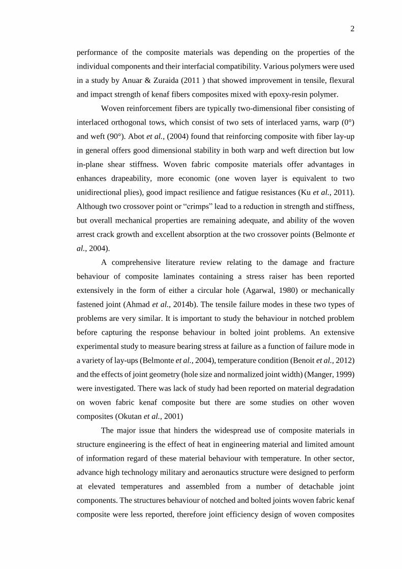
Polymer composites have emerged as important structural engineering materials in
automotive, transportation, infrastructure applications as well as in civil engineering
sector, mainly due to excellent specific strength and stiffness. Composite materials are
one of a new class of advanced materials that are strong, possess low densities, and
non-corrosive. Commercially available composite materials are carbon fiber-
reinforced polymer (CFRP), glass fiber-reinforced polymer (GFRP) and Kevlar fiber-
reinforced composite. Composites material are comprised of two or more distinct
phase elements, including reinforcing phase (fiber, sheet or particles) and matrix phase
(polymer, ceramic or metal). Polymer matrix composites production are commercially
produced worldwide and used in larger engineering sectors. Two polymer types,
thermoplastic and thermoset polymers are used in various types of reinforcing fibers
such as man-made-fiber and natural fiber (plant, animal, mineral).
Recently, natural fibers have attracted attention in composite material research
due to advantages such as renewable, environmental-friendly and cheaper option
(Mittal et al., 2016). Over the last decade, natural fiber has replaced material researcher
interest as a substitute for synthetic fiber due to awareness of environmental issue and
enforcement of stringent environmental assessment of material productions in future.
Kenaf fiber exhibits superior specific strength and stiffness, less abrasive during
handling and biodegradability (Nishino et al., 2006). Hajnalka et al., (2008) found out
optimum young’s modulus of fiber composites increased as the fiber fraction increased
to 50%, but decreased gradually as further increased to 70%. It is well understood that
2
performance of the composite materials was depending on the properties of the
individual components and their interfacial compatibility. Various polymers were used
in a study by Anuar & Zuraida (2011 ) that showed improvement in tensile, flexural
and impact strength of kenaf fibers composites mixed with epoxy-resin polymer.
Woven reinforcement fibers are typically two-dimensional fiber consisting of
interlaced orthogonal tows, which consist of two sets of interlaced yarns, warp (0°)
and weft (90°). Abot et al., (2004) found that reinforcing composite with fiber lay-up
in general offers good dimensional stability in both warp and weft direction but low
in-plane shear stiffness. Woven fabric composite materials offer advantages in
enhances drapeability, more economic (one woven layer is equivalent to two
unidirectional plies), good impact resilience and fatigue resistances (Ku et al., 2011).
Although two crossover point or “crimps” lead to a reduction in strength and stiffness,
but overall mechanical properties are remaining adequate, and ability of the woven
arrest crack growth and excellent absorption at the two crossover points (Belmonte et
al., 2004).
A comprehensive literature review relating to the damage and fracture
behaviour of composite laminates containing a stress raiser has been reported
extensively in the form of either a circular hole (Agarwal, 1980) or mechanically
fastened joint (Ahmad et al., 2014b). The tensile failure modes in these two types of
problems are very similar. It is important to study the behaviour in notched problem
before capturing the response behaviour in bolted joint problems. An extensive
experimental study to measure bearing stress at failure as a function of failure mode in
a variety of lay-ups (Belmonte et al., 2004), temperature condition (Benoit et al., 2012)
and the effects of joint geometry (hole size and normalized joint width) (Manger, 1999)
were investigated. There was lack of study had been reported on material degradation
on woven fabric kenaf composite but there are some studies on other woven
composites (Okutan et al., 2001)
The major issue that hinders the widespread use of composite materials in
structure engineering is the effect of heat in engineering material and limited amount
of information regard of these material behaviour with temperature. In other sector,
advance high technology military and aeronautics structure were designed to perform
at elevated temperatures and assembled from a number of detachable joint
components. The structures behaviour of notched and bolted joints woven fabric kenaf
composite were less reported, therefore joint efficiency design of woven composites
3
exposed to elevated temperatures is difficult due to lacking of available experimental
data. Influence of temperature are great importance as the composite material may
degrade in service due frequently expose to in evaluated temperature environment
where temperature ranging from 100-200°C. As reported by Smith (2000), with
increasing temperature, the matrix dominated properties of composite was similar
influenced by softening of the matrix in particular as temperature approach the matrix
glass transition temperature. Matrix dominated properties such as the transverse and
shear stiffness and strength was reduced. On the other hand, modulus parallel to fibers
(𝐸1) was relatively temperature insensitive as would be expected for a fiber dominated
property.
1.2 Problem Statements
Currently, commercial fibers such as carbon and glass fibers are used excessively in
production of composite materials. Commercial fibers are man-made, its aggressive
production become an environmental issue as it is non-renewability, non-
environmentally friendly and contain chemical contaminants. The commercial fibers
are synthetically manufactured outside Malaysia, these materials are regarded as
imported goods and has limited use due to high cost. As highlighted in Tenth Malaysia
Plan (RMK-10), it was focused upon production of renewable resource and sustainable
materials, production of natural fibers are the best option to reduce synthetic fibers
production (Economic, 2010). Natural fibers are potentially used as composite
reinforcement and excellent engineering material properties were reported but there
are lacking in experimental works in joining assembly and if convincing, it can be
utilized as local-production industry and enable broader applications of kenaf fiber
composites in Malaysia (Hadi et al., 2014), kenaf plants are largely planted in east
coast and northern Malaysia. Kenaf fiber can be weaved into woven fabrics and
classify as an important fiber reinforcing class, excellent in resisting impact and fatigue
loading. However, due to crimping region exhibited, this composite class is relatively
complex than non-woven composite counterparts (Saiman et al., 2014).
Composite materials exposed to elevated temperature condition tends to
degrades its mechanical and durability properties and these affect the structures
performance and corresponding costs as a results of rehabilitation works. The polymer
binder sensitive to temperature changes and leading to disintegration of fiber and
4
matrix bonding and therefore may reduce its structural strength. Complex damage
morphologies in composite plates with discontinuities such as open-hole and cut-outs
is exhibited, more complex when subjected to temperature actions. Stress
concentrations develop cohesive damage ahead of notch tip as tensile loading applied.
Analytical approach by Aronsson & Backlund (1986) implemented simplified
cohesive stress-separation relationship in their strength prediction work of GFRP
plates, later work explores more comprehensive modelling based on ply-by-ply
modelling known as “progressive damage modelling”. Santiuste et al., (2011) used
numerical approach progressive damage modelling approach to combine failure
criteria (Hashin, 1980) and degradation model (Yamada & Sun, 1978) in order to study
strength prediction under temperature effect by developing their own programming
subroutine to predict bearing strength at failure and gave mixture of prediction
accuracy. However, these approach is suitable to bearing failure mode as it was based
on ply-by-ply basis, however woven fabric composites is more prominent to net-
tension failure type which is associated with stress concentration.
Several parameters were involved in bolted joint problems, analytical
approaches seems unrealistic as huge numbers of parameters involved. The obstacle
in finite element modelling of testing coupons associated with stress concentration is
the occurrence of singularity ahead of crack tip. Previously, these requires refined
meshing ahead of notch tip in finite element modelling framework, however with the
introduction of extended finite element framework (XFEM) techniques eliminates
these requirement as it is driven by energetic approach. Ahmad et al., (2013) has
successfully conducted Extended Finite Element Method (XFEM) framework
approach in predicting joint strength of woven fabric CFRP composites with notched
coupons and single-lap bolted joints (Ahmad et al., 2014b), but no study on strength
prediction work under elevated temperature action has been reported. Therefore, this
study explores strength prediction works of woven fabric kenaf composite by using
XFEM approach by implementing physically-based traction-separation as a
constitutive model on notched and bolted joints problems under temperature actions.
The strength prediction were then validated against experimental dataset and to
develop a methodology that is applicable to tensile failure at notched and net-tension
failure in bolted joints under temperature action.
5
1.3 Objectives
This project is concerned with strength prediction work of notched and bolted joints
woven fabric kenaf composite polymer under room temperature and elevated
temperature by physically-based constitutive model to be implemented within finite
element framework, explicitly used measured independently material parameter from
experiment. The aim is to develop a methodology that is applicable to tensile failure
at notched and net-tension failure in bolted joints under temperature action.
1.4 Scope of study
In the present study, woven fabric kenaf composite are fabricated at Universiti Tun
Hussein Onn Malaysia fabrication laboratory. Firstly, kenaf yarns with diameter of 0.7
mm are orthogonally weaved using a weaving handloom machine to produce required
numbers of woven (plain weave) fabric layers. Fabrication stage was carried out using
in-house wet lay-up technique and bound with epoxy resin and hardener as matrix
under high pressure. Polymer composite harden for 24 hours under high pressure with
ratio 2:1 epoxy and hardener as mixture matrix had few drawbacks such us a very long
curing process and handmade draping that generates most of the non-reversible defect
of the manufacturing process.
Temperature control system from laboratory oven provides a stable
temperature environment within drying exposure duration. For under elevated
temperature (prescribed as 120˚C as in Table 2.4) condition, woven fabric kenaf
composite coupons were dried-oven at 70 ± 5˚C for 48 hours and preserved in
waterproof environment so that the testing coupons were considered as dry coupons.
Mechanical testing of testing coupon were carried out within 8 hours after oven-dried.
These procedures were applied in both open hole coupons and bolted joints problem.
Relevant code of practice was used as references in order to determine the in-
plane tensile properties (𝐸𝑥, 𝐺𝑥𝑦 and 𝜎0) ASTM D3039 (Standard test method for
tensile of polymer matrix composite material properties) and ASTM E399-90
(Standard test method for plane-strain fracture toughness of metallic materials) was
referred to measure critical strain energy release or known as fracture energy, 𝐺𝑐.
Length change datasets were gained by using strain gauge and mechanical testing are
6
conducted by using Universal Testing Machine under quasi-static loading with
crosshead speed of 0.5 mm/min, and a load cell of 100 kN.
In the notched problem, the gauge lengths of 150 mm were used throughout
the testing series. The width was kept constant as 25 mm with the hole diameter, d of
2.5 mm, 5.0 mm, and 10 mm to give 𝑑 𝑊⁄ ratio of 0.1, 0.2 and 0.4, respectively. The
mechanical testing was carried out, where applied load and strain datasets was
recorded at one-second intervals using a PC data-logging package from Instron
machine. In bolted joints problem, the bolt and washer size of 5 mm (commercial code
as M5) was used as fastener system and assembled accordingly to single-lap joint
configuration prior to finger-tight clamping load (0.5 N). Mechanical testing was
conducted immediately after the implementation of bolt load to eliminate bolt
relaxations.
Three-dimensional finite element analysis (FEA) framework using ABAQUS
CAE Version 6.13 software package were conducted with XFEM framework approach
to includes proper surface interactions, friction coefficient to allow joint load transfer,
bolt load to provide through-thickness compression and washer were modelled
explicitly (most previous researchers ignores the washer in their model) for simplicity.
Current work emphasized on effect of temperature which explicitly included in the
XFEM modelling framework. The validation works compare the discrepancies
between XFEM predicted strength with experimental datasets as described earlier.
1.5 Organization of thesis
To achieve the objective of in the previous section, the study has been structure down
to the following chapter. Chapter 2 gives comprehensive study of previous works of
related topics that provides good background to present project work. It describes the
physical characteristics of woven fabric yarns and associated reinforced polymer
composites. This is followed with the description on material behaviour of composite
materials under temperature actions, and mechanical properties of natural fiber to
focus on implementation of kenaf fibers in composite materials. The experimental
study of open hole coupon and bolted joints of composite coupons by previous
researchers were described. Associated strength prediction approach in open hole
problem and mechanical fastened composite coupon are further discussed.
7
Chapter 3 concerned on two-dimensional (2-D) finite element modelling of
open hole woven fabric kenaf composite coupons using ABAQUS CAE software.
Prior to modelling work, experimental framework comprised of material preparations,
panel fabrication and testing series were discussed concurrently. The independent
properties for physical-based constitutive model used in strength prediction works
were discussed. Extended finite element method (XFEM) framework were
implemented in the numerical modelling incorporated of traction-separation
relationship to study open hole coupon behaviour. Benchmarking works on previous
researcher and strength prediction with effect of elevated temperature of open hole
problem were also conducted.
Chapter 4 describes an experimental framework for woven fabric kenaf
composite coupon bolted joints. The lay-up used was a subset in open hole problem
discussed in Chapter 3. A test matrix is developed on single-lap joint with different
W/d, temperature effects, lay-up types and coupon thickness. The experimental results
of these parametric variations were discussed with observations during mechanical
testing and associated bearing stress at failure. The experimental results obtained from
this chapter was used as a validation work of finite element modelling as reported in
Chapter 5.
Chapter 5 discussed on 3-D FEA modelling of single-lap bolted joint woven
fabric kenaf composite under elevated temperature and compared to experimental
results as reported in Chapter 4. Pre-processing stages of modelling idealization,
discretization, generation of coupon geometry and material properties as well as
loading and boundary condition were elaborated. The strength predictions framework
includes the sensitivity study to incorporate explicitly bolt load, loads friction transfer
and contact interactions. The discrepancy with experimental bearing stress at failure
of testing series in single-lap bolted joint under room and elevated temperatures were
discussed.
Conclusions are presented and recommendations for future works were given
in last chapter.
CHAPTER 2
LITERATURE REVIEW
2.1 Introduction
This chapter started with introduction of physical characteristic of woven fabric plies
to emphasize upon undulation region, followed by discussion on the effect of extreme
temperature upon strength in composite materials. Subsequent section discussed the
type of natural fibers, mainly focus on physical and engineering properties of kenaf
fibers. Following section discussed the notched coupons, ranging from experimental
observation under room temperatures and elevated temperatures and associated
strength prediction approaches. This followed with the discussion on bolted joints
problem, similar subsection as given in previous (notched) section. Concluding
remarks is summarized in the last section
Composite materials are manufactured by combining two or more different
materials to obtain an advanced material with superior mechanical, chemical, thermal
etc. that is unachievable by its constituent alone. Compared to isotropic materials such
as steel or aluminium, composite materials perform relatively complex behaviour due
to its anisotropic characteristics. Effects of elevated temperatures need to take into
account at the early design stage, or consequences of catastrophic failures. Finite
element analysis (FEA) is the most powerful tool to study the structures response of
composite materials with the evolution of advanced computing technology.
.
9
2.2 Natural Fibers
Natural fiber is a class of hair-like materials that are continuous filaments or in discrete
elongated pieces, spun to form filaments, thread, or rope to use as a material
component. The implementation of natural fibers as reinforcements in polymer
composites are to replace commercial synthetic fibers like glass is presently receiving
increasing attention because it offers cost effectiveness, low density, excellent specific
strength and renewable resources. Since 1990s, natural fiber composites are emerging
as realistic alternatives to glass-reinforced composites in many applications. Natural
fiber composites such as hemp fiber-epoxy, flax fiber-polypropylene (PP), and china
reed fiber-PP are particularly attractive in automotive applications due to lower cost
and density. Glass fibers used for composites have density of 2.6 g/cm3 and cost
between USD 1.30/kg and USD 2.00/kg. On the other hand, flax fibers density are
approximately 1.5 g/cm3 and cost between USD 0.22 and USD 1.10/kg (Foulk et al.,
2000).
Testing samples of 40% fiber content of. kenaf, coir, sisal, hemp, and jute
combined with polypropylene binders are tested to replace glass fiber–reinforced
materials (Wambua et al., 2003). Polypropylene with high melting flow index was
used to aid in fiber matrix adhesion and to ensure proper wetting of the fibers. Tensile
strengths of all testing samples were comparable with glass fiber composites except
for the coir composites, but only hemp fiber has similarity flexural strength. It was
shown that increasing fiber weight fraction of kenaf fibers increased ultimate strength,
tensile modulus, and impact strength. However, the composites tested showed low
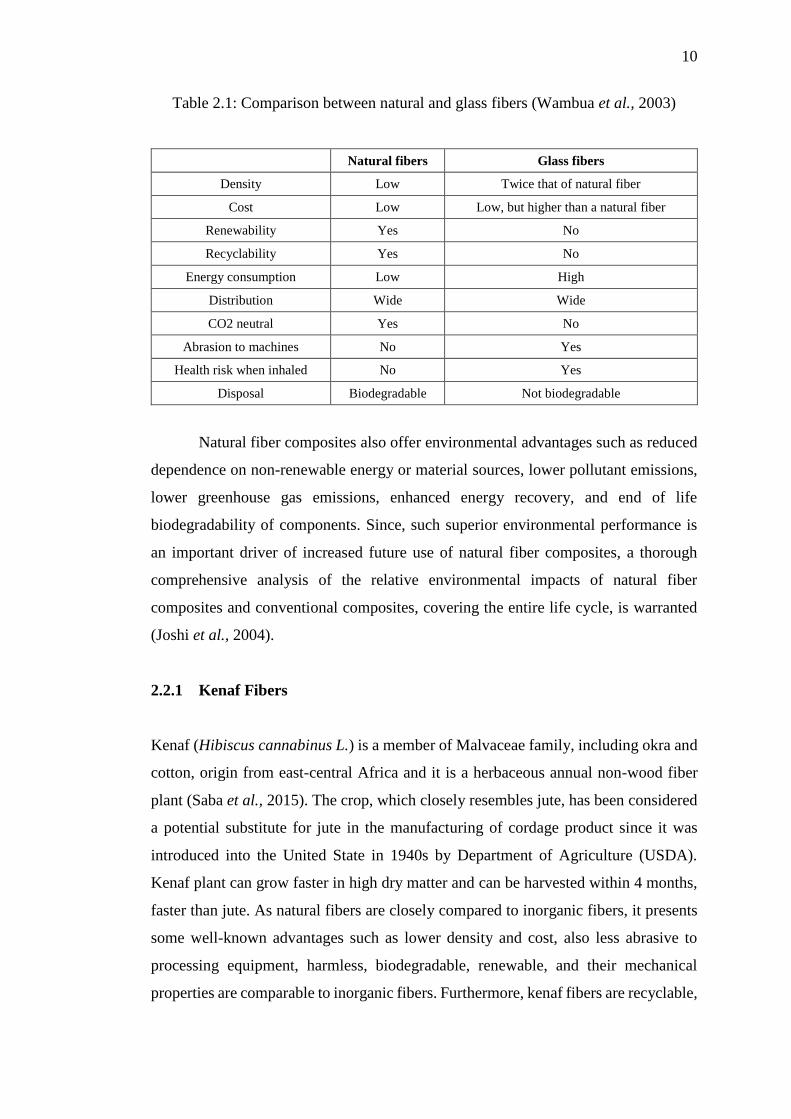
impact strengths compared to glass mat composites as shown in Table 2.1. Wambua
et al. (2003) mention in his study demonstrated that natural fiber composites have a
potential to replace glass under low or medium load bearing applications.
10
Table 2.1: Comparison between natural and glass fibers (Wambua et al., 2003)
Natural fibers Glass fibers
Density Low Twice that of natural fiber
Cost Low Low, but higher than a natural fiber
Renewability Yes No
Recyclability Yes No
Energy consumption Low High
Distribution Wide Wide
CO2 neutral Yes No
Abrasion to machines No Yes
Health risk when inhaled No Yes
Disposal Biodegradable Not biodegradable
Natural fiber composites also offer environmental advantages such as reduced
dependence on non-renewable energy or material sources, lower pollutant emissions,
lower greenhouse gas emissions, enhanced energy recovery, and end of life
biodegradability of components. Since, such superior environmental performance is
an important driver of increased future use of natural fiber composites, a thorough
comprehensive analysis of the relative environmental impacts of natural fiber
composites and conventional composites, covering the entire life cycle, is warranted
(Joshi et al., 2004).
2.2.1 Kenaf Fibers
Kenaf (Hibiscus cannabinus L.) is a member of Malvaceae family, including okra and
cotton, origin from east-central Africa and it is a herbaceous annual non-wood fiber
plant (Saba et al., 2015). The crop, which closely resembles jute, has been considered
a potential substitute for jute in the manufacturing of cordage product since it was
introduced into the United State in 1940s by Department of Agriculture (USDA).
Kenaf plant can grow faster in high dry matter and can be harvested within 4 months,
faster than jute. As natural fibers are closely compared to inorganic fibers, it presents
some well-known advantages such as lower density and cost, also less abrasive to
processing equipment, harmless, biodegradable, renewable, and their mechanical
properties are comparable to inorganic fibers. Furthermore, kenaf fibers are recyclable,
11
easily available in most countries, easy surface modification, and has relative non-
abrasiveness (Li et al., 2008; George et al., 2001). Therefore, many ongoing research
were carried out on many different aspects of kenaf fiber properties (physical,
mechanical etc.), cultivating, producing and recycling process and the potential
markets (Salman et al., 2015).
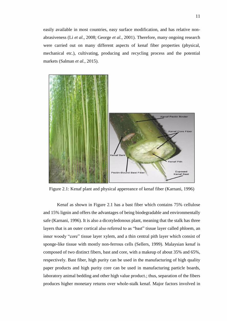
Figure 2.1: Kenaf plant and physical appereance of kenaf fiber (Karnani, 1996)
Kenaf as shown in Figure 2.1 has a bast fiber which contains 75% cellulose
and 15% lignin and offers the advantages of being biodegradable and environmentally
safe (Karnani, 1996). It is also a dicotyledonous plant, meaning that the stalk has three
layers that is an outer cortical also referred to as “bast” tissue layer called phloem, an
inner woody “core” tissue layer xylem, and a thin central pith layer which consist of
sponge-like tissue with mostly non-ferrous cells (Sellers, 1999). Malaysian kenaf is
composed of two distinct fibers, bast and core, with a makeup of about 35% and 65%,
respectively. Bast fiber, high purity can be used in the manufacturing of high quality
paper products and high purity core can be used in manufacturing particle boards,
laboratory animal bedding and other high value product.; thus, separation of the fibers
produces higher monetary returns over whole-stalk kenaf. Major factors involved in
12
separation of kenaf into its two fractions include size and amount of each portion; type
and number of separation machinery or processing rate through separation machinery;
moisture content of whole-stalk kenaf; humidity of ambient air (Abdul Khalil et al.,
2010).
The traditional use of kenaf was formerly seen in manufacturing of sacking,
cordage, ropes, fishing nets, etc. During the past decades, researchers have been
seeking other potential markets for kenaf to take advantage from an environmental
point of view. However, the success of a new crop venture needs market development.
In 1992, Jobes and Dicks stated that an immediate potential market would be
newsprint, poultry litter and forage. In the pulp and paper industries, kenaf has been
expected to serve as an alternate non-wood fiber because it can help in reducing the
deforestation worldwide and have a favorable impact on the economies of many
developing and developed countries (Kaldor, 1992). Currently, commercial interest in
kenaf fibers among natural non-wood fibers is growing in the fields of textile and
automobile.
2.2.2 Characteristics and Engineering Properties of Kenaf Fibers
Table 2.2 showed the characteristic and properties of kenaf stems in Malaysia. Kenaf
has used intensity in industry as renewable resource material. Kenaf has ability to fix
CO2 has expand global awareness as a natural fiber source. Harvesting kenaf take 4
months and able to plant in dry area. The physical properties of kenaf has determine
that the maximum plant could growth about height 250 cm and the lowest was 145 cm
as in Table 2.2. The maximum and minimum of kenaf diameter stem could reach 30
mm and 14 mm respectively. The density of kenaf are light in related to its dimension
about 0.29 g/cm3 and this could advantage using kenaf in replacement inorganic
material.
13
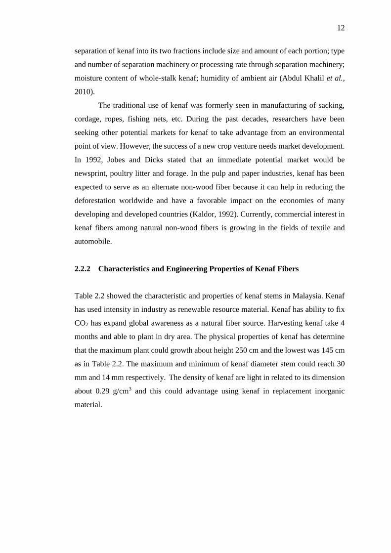
Table 2.2: Characteristic and properties of kenaf stems, Malaysia
(Abdul Khalil et al., 2010)
Characteristic /
Properties Bast Core Stem
Dimension (cm)
Height (range) (cm)
Diameter (mm)
Perimeter (cm)
-
-
-
-
-
-
-
-
-
145-250
14 - 30
6.60 (0.044)
Proportion (%)
Cross-section area
Weight proportion
-
21.96(2.03)
32.2
-
78.04(2.51)
68.5
-
-
-
Density (g/cm3) - 0.21(0.038) 0.29(0.044)
Acidity (pH) 7.13 5.21 5.87
Excellent tensile strength and modulus of kenaf fibers were reported by
previous researchers (Dauda et al., 2014). He found that dry woven kenaf obtain better
modulus result than higher moisture content. Compression molded kenaf-PP
composites had shown greater tensile strength and flexural strength compared to other
natural fibers. Kenaf-PP had lower elongation at break, thus, providing higher value
of tensile strength which is about 930 MPa. The properties of natural fibers showed in
Table 2.3.
Table 2.3: Mechanical properties of natural fibers
(Wambua et al., 2003)
Properties Hemp Jute Ramie Coir Sisal Flax Cotton Kenaf
Density, (g/cm3) 1.48 1.46 1.5 1.25 1.33 1.4 1.51 1.4
Tensile Strength,
(MPa)
550-
990
400-
800 500 220
600-
700
800-
1500 400
283-
800
E-Modulus, (GPa) 70 10-30 44 6 38 60-80 12 21-60
Specific, (E/d) 47 7-21 29 5 29 26-46 8 22-40
Elongation at
failure, (%) 1.6 1.8 2
15-
25 2-3 1.2-1.6 3-10 1.6
Moisture
absorption, (%) 8 12 12-17 10 11 7 8-25 -
14
2.3 Configuration of Woven Fabric Fiber
In polymeric composite terminology, a woven fabric was defined as a manufactured
assembly of long yarn fibers to produce a flat sheet of one or more layers of fibers.
These layers are held together either by mechanical interlocking of the fibers
themselves or with a secondary material to bind these fibers together and hold them in
place, giving the assembly sufficient integrity to be handled. Fabric types are
categorized by the orientation of the fibers and various construction methods used to
hold the fibers together. The four main fiber orientation categories are unidirectional,
0/90 (woven, stitched or hybrid), multiaxial, and random fibers. This work focused on
woven fabrics type as described in next paragraph.
For applications where more than one fiber orientation is required, a fabric
combining 0° and 90° fiber orientations are useful. Woven fabrics are made by
interlacing of warp (0°) fibers and weft (90°) fibers in a regular weave pattern. The
fabric’s integrity is maintained by the mechanical interlocking of the fibers (Saiman et
al., 2014). Drapability (the ability of a fabric to conform to a complex surface), surface
smoothness and stability of a fabric are controlled primarily by the weave style. The
area weight, porosity and (to a lesser degree) wet out are determined by selecting the
correct combination of fiber and thread counts (fibers/cm). Some of the commonly
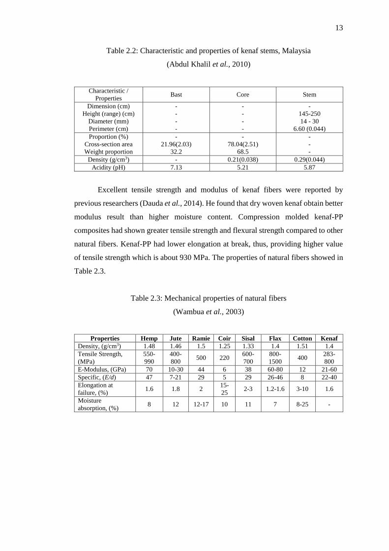
found weave styles are plain, twill, satin weave as shown in Figure 2.2.
Figure 2.2: Various type of woven fabric type (Dixit & Harlal, 2013)

15
Plain weave fabric are symmetrical, possesses good stability and considered to
fulfil consideration required to in-plane loading direction applied (Benoit et al., 2011).
However, it has low drapeability and high level of fiber crimp imparts relatively low
mechanical properties compared with the other weave styles (Salman et al., 2015).
Fiber acts as a reinforcement to improve the mechanical properties of polymer and
their primary function is to withstand the applied multi-loads acting on the composite.
The matrix material binds the fiber yarns together, protects them, and distributes loads.
Even though the mechanical properties of polymers may improve by adding filler or
other agents, actual strength properties are usually accredited to the fiber properties.
Figure 2.3: Plain weave kenaf (a) top view (b) side cross-section view
(Salman et al., 2015)
Figure 2.3 illustrate a plain weave fiber, P1 and P2 represent the distance
between warp and weft. Since the woven kenaf fabric weaving using the handloom
lay-up technique, the distance between warp and weft are inconsistent. The fiber
diameter denotes as d1 and d2 with t indicated as thickness of woven. The laminate
staking sequence enhance the strength in respective lamina primary loading direction.
Figure 2.4 are illustration of laminate staking sequence used in the experimental work
to study the strength of composite coupon. The laminate consists ± 45º degree direction
stated as quasi-isotropic either combined with 0º degree direction and the cross-ply
laminate consist only 0º and 90º degrees in the laminate composite coupon.
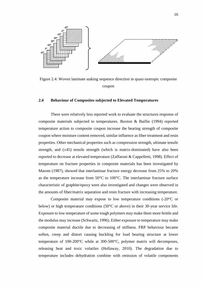
16
Figure 2.4: Woven laminate staking sequence direction in quasi-isotropic composite
coupon
2.4 Behaviour of Composites subjected to Elevated Temperatures
There were relatively less reported work to evaluate the structures response of
composite materials subjected to temperatures. Buxton & Baillie (1994) reported
temperature action to composite coupon increase the bearing strength of composite
coupon where moisture content removed, similar influence as fiber treatment and resin
properties. Other mechanical properties such as compression strength, ultimate tensile
strength, and (±45) tensile strength (which is matrix-dominated) have also been
reported to decrease at elevated temperature (Zaffaroni & Cappelletti, 1998). Effect of
temperature on fracture properties in composite materials has been investigated by
Marom (1987), showed that interlaminar fracture energy decrease from 25% to 20%
as the temperature increase from 50°C to 100°C. The interlaminar fracture surface
characteristic of graphite/epoxy were also investigated and changes were observed in
the amounts of fiber/matrix separation and resin fracture with increasing temperature.
Composite material may expose to low temperature conditions (-20°C or
below) or high temperature conditions (50°C or above) in their 30-year service life.
Exposure to low temperature of some tough polymers may make them more brittle and
the modulus may increase (Schwartz, 1996). Either exposure to temperature may make
composite material ductile due to decreasing of stiffness. FRP behaviour became
soften, creep and distort causing buckling for load bearing structure at lower
temperature of 100-200°C while at 300-500°C, polymer matrix will decomposes,
releasing heat and toxic volatiles (Hollaway, 2010). The degradation due to
temperature includes dehydration combine with emission of volatile components
17
initiating at a temperature of about 260°C and rapid weight loss due to oxidation
decomposition. In terms of exposure to high temperature, majority of natural fibers
have low degradation temperature, where kenaf fiber degrade at 297-434°C (Aziz &
Ansell, 2004).
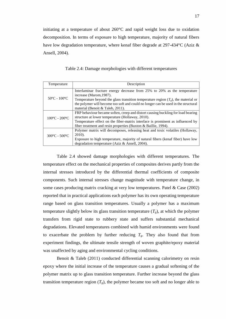
Table 2.4: Damage morphologies with different temperatures
Temperature Description
50ºC - 100ºC
Interlaminar fracture energy decrease from 25% to 20% as the temperature
increase (Marom,1987).
Temperature beyond the glass transition temperature region (Tg), the material or
the polymer will become too soft and could no longer can be used in the structural
material (Benoit & Taleb, 2011).
100ºC - 200ºC
FRP behaviour became soften, creep and distort causing buckling for load bearing
structure at lower temperature (Hollaway, 2010).
Temperature effect on the fiber-matrix interface is prominent as influenced by
fiber treatment and resin properties (Buxton & Baillie, 1994).
300ºC - 500ºC
Polymer matrix will decomposes, releasing heat and toxic volatiles (Hollaway,
2010).
Exposure to high temperature, majority of natural fibers (kenaf fiber) have low
degradation temperature (Aziz & Ansell, 2004).
Table 2.4 showed damage morphologies with different temperatures. The
temperature effect on the mechanical properties of composites derives partly from the
internal stresses introduced by the differential thermal coefficients of composite
components. Such internal stresses change magnitude with temperature change, in
some cases producing matrix cracking at very low temperatures. Patel & Case (2002)
reported that in practical applications each polymer has its own operating temperature
range based on glass transition temperatures. Usually a polymer has a maximum
temperature slightly below its glass transition temperature (Tg), at which the polymer
transfers from rigid state to rubbery state and suffers substantial mechanical
degradations. Elevated temperatures combined with humid environments were found
to exacerbate the problem by further reducing Tg. They also found that from
experiment findings, the ultimate tensile strength of woven graphite/epoxy material
was unaffected by aging and environmental cycling conditions.
Benoit & Taleb (2011) conducted differential scanning calorimetry on resin
epoxy where the initial increase of the temperature causes a gradual softening of the
polymer matrix up to glass transition temperature. Further increase beyond the glass
transition temperature region (Tg), the polymer became too soft and no longer able to
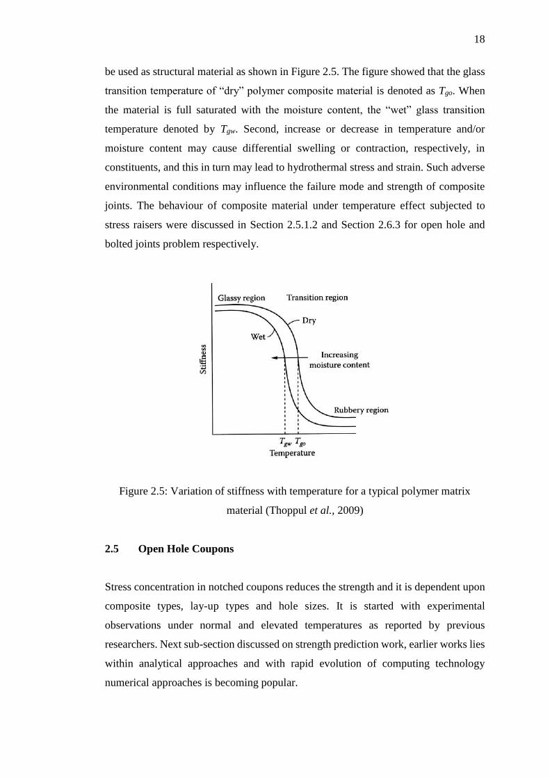
18
be used as structural material as shown in Figure 2.5. The figure showed that the glass
transition temperature of “dry” polymer composite material is denoted as Tgo. When
the material is full saturated with the moisture content, the “wet” glass transition
temperature denoted by Tgw. Second, increase or decrease in temperature and/or
moisture content may cause differential swelling or contraction, respectively, in
constituents, and this in turn may lead to hydrothermal stress and strain. Such adverse
environmental conditions may influence the failure mode and strength of composite
joints. The behaviour of composite material under temperature effect subjected to
stress raisers were discussed in Section 2.5.1.2 and Section 2.6.3 for open hole and
bolted joints problem respectively.
Figure 2.5: Variation of stiffness with temperature for a typical polymer matrix
material (Thoppul et al., 2009)
2.5 Open Hole Coupons
Stress concentration in notched coupons reduces the strength and it is dependent upon
composite types, lay-up types and hole sizes. It is started with experimental
observations under normal and elevated temperatures as reported by previous
researchers. Next sub-section discussed on strength prediction work, earlier works lies
within analytical approaches and with rapid evolution of computing technology
numerical approaches is becoming popular.
19
2.5.1 Experimental Study on Notched Coupons
This sub-chapter focus on notches coupons to concentrate upon the behaviour of
composite coupon applied to load and mechanical properties by previous researchers.
Notched coupon refers to a discontinuity of composite coupon coupon, in the form of
open hole, cracks or cutouts that create stress concentration to initiate crack formation
and propagation. This study focused on circular hole coupon also includes the
parametric study such as lay-up types, hole size and coupon thicknesses. These
sections discussed the experimental study of notched coupon under room temperatures
and followed by effect of elevated temperatures on notched testing coupons.
2.5.1.1 Experimental Study on Notched Coupon Under Room Temperature
Coupons with discontinuities such as notches and cutouts leads to damage zone
formation and associated to strength degradation. The notch sensitivity was defined as
a ratio of the notched strength to unnotched strength and its ability to accommodate
fracture and failure at hole vicinity. Interlaminar damage at the notch tips provides
stress relief as the notch geometry changed and correspondingly the stress
concentration is reducing, therefore increasing the notched strength. Large damage
zone generally provides more stress relief and hence greater notch strength. If
interlaminar damage are extensive, it reduce the notched strength as individual
uncoupled piles are free to fail by the fracture mode of least resistance (Harris &
Morris, 1986). The damage initation and progression is depending on several factor
such as staking sequence, notch geometry, testing temperature, matrix laminate,
reinforcement type, hole size and shape, number of fabric lay-up and woven fabric
orientation.
Effect to staking sequence and laminate lay-up, (Eriksson & Aronsson, 1990)
showed 0° ply dominated laminate had higher notched strength and exhibited more
damage prior to failure than ±45° and 90° ply dominated laminate. In the Harris &
Morris (1986) research, they carried out a study the effect of staking sequences and
showed that notched strength were varied with fiber orientation and staking sequence
piles. Both them examined the laminate thickness and found that in thick laminate
failure damage near notch only at outer plies but the greater laminate thickness takes
less effect damage on the stress distribution prior to failure.
20
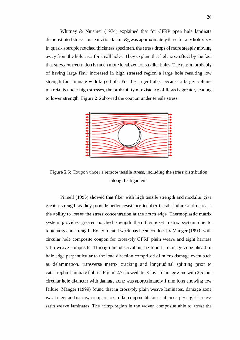
Whitney & Nuismer (1974) explained that for CFRP open hole laminate
demonstrated stress concentration factor KT, was approximately three for any hole sizes
in quasi-isotropic notched thickness specimen, the stress drops of more steeply moving
away from the hole area for small holes. They explain that hole-size effect by the fact
that stress concentration is much more localized for smaller holes. The reason probably
of having large flaw increased in high stressed region a large hole resulting low
strength for laminate with large hole. For the larger holes, because a larger volume
material is under high stresses, the probability of existence of flaws is greater, leading
to lower strength. Figure 2.6 showed the coupon under tensile stress.
Figure 2.6: Coupon under a remote tensile stress, including the stress distribution
along the ligament
Pinnell (1996) showed that fiber with high tensile strength and modulus give
greater strength as they provide better resistance to fiber tensile failure and increase
the ability to losses the stress concentration at the notch edge. Thermoplastic matrix
system provides greater notched strength than thermoset matrix system due to
toughness and strength. Experimental work has been conduct by Manger (1999) with
circular hole composite coupon for cross-ply GFRP plain weave and eight harness
satin weave composite. Through his observation, he found a damage zone ahead of
hole edge perpendicular to the load direction comprised of micro-damage event such
as delamination, transverse matrix cracking and longitudinal splitting prior to
catastrophic laminate failure. Figure 2.7 showed the 8-layer damage zone with 2.5 mm
circular hole diameter with damage zone was approximately 1 mm long showing tow
failure. Manger (1999) found that in cross-ply plain weave laminates, damage zone
was longer and narrow compare to similar coupon thickness of cross-ply eight harness
satin weave laminates. The crimp region in the woven composite able to arrest the
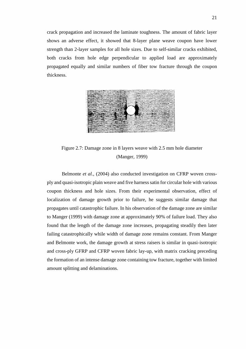
21
crack propagation and increased the laminate toughness. The amount of fabric layer
shows an adverse effect, it showed that 8-layer plane weave coupon have lower
strength than 2-layer samples for all hole sizes. Due to self-similar cracks exhibited,
both cracks from hole edge perpendicular to applied load are approximately
propagated equally and similar numbers of fiber tow fracture through the coupon
thickness.
Figure 2.7: Damage zone in 8 layers weave with 2.5 mm hole diameter
(Manger, 1999)
Belmonte et al., (2004) also conducted investigation on CFRP woven cross-
ply and quasi-isotropic plain weave and five harness satin for circular hole with various
coupon thickness and hole sizes. From their experimental observation, effect of
localization of damage growth prior to failure, he suggests similar damage that
propagates until catastrophic failure. In his observation of the damage zone are similar
to Manger (1999) with damage zone at approximately 90% of failure load. They also
found that the length of the damage zone increases, propagating steadily then later
failing catastrophically while width of damage zone remains constant. From Manger
and Belmonte work, the damage growth at stress raisers is similar in quasi-isotropic
and cross-ply GFRP and CFRP woven fabric lay-up, with matrix cracking preceding
the formation of an intense damage zone containing tow fracture, together with limited
amount splitting and delaminations.
22
2.5.1.2 Experimental Study on Notched Coupon Subjected to Elevated
Temperature
The temperature action was of great importance to study as a material is weakening
under temperature conditions. In service, composite materials are frequency exposed
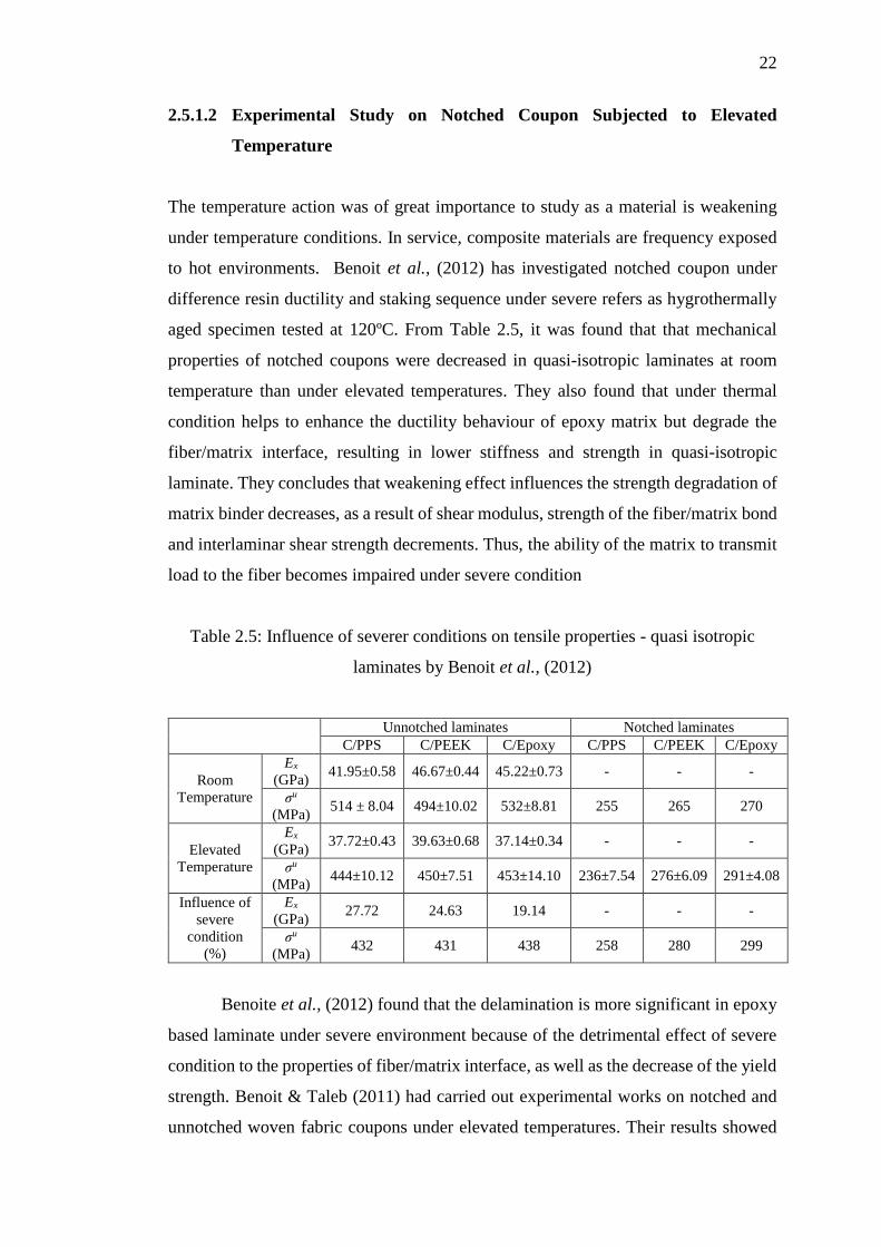
to hot environments. Benoit et al., (2012) has investigated notched coupon under
difference resin ductility and staking sequence under severe refers as hygrothermally
aged specimen tested at 120ºC. From Table 2.5, it was found that that mechanical
properties of notched coupons were decreased in quasi-isotropic laminates at room
temperature than under elevated temperatures. They also found that under thermal
condition helps to enhance the ductility behaviour of epoxy matrix but degrade the
fiber/matrix interface, resulting in lower stiffness and strength in quasi-isotropic
laminate. They concludes that weakening effect influences the strength degradation of
matrix binder decreases, as a result of shear modulus, strength of the fiber/matrix bond
and interlaminar shear strength decrements. Thus, the ability of the matrix to transmit
load to the fiber becomes impaired under severe condition
Table 2.5: Influence of severer conditions on tensile properties - quasi isotropic
laminates by Benoit et al., (2012)
Unnotched laminates Notched laminates
C/PPS C/PEEK C/Epoxy C/PPS C/PEEK C/Epoxy
Room
Temperature
Ex
(GPa) 41.95±0.58 46.67±0.44 45.22±0.73 - - -
σu
(MPa) 514 ± 8.04 494±10.02 532±8.81 255 265 270
Elevated
Temperature
Ex
(GPa) 37.72±0.43 39.63±0.68 37.14±0.34 - - -
σu
(MPa) 444±10.12 450±7.51 453±14.10 236±7.54 276±6.09 291±4.08
Influence of
severe
condition
(%)
Ex
(GPa) 27.72 24.63 19.14 - - -
σu
(MPa) 432 431 438 258 280 299
Benoite et al., (2012) found that the delamination is more significant in epoxy
based laminate under severe environment because of the detrimental effect of severe
condition to the properties of fiber/matrix interface, as well as the decrease of the yield
strength. Benoit & Taleb (2011) had carried out experimental works on notched and
unnotched woven fabric coupons under elevated temperatures. Their results showed

23
that in quasi-isotropic lay-up [0/45/0/45/0/45/0], material strength were decrease
within 5-12% under temperature condition where material stiffness decrease by less
than 10%. In other word, there is relative high degree retention of mechanical
properties despite critical tests condition. Benoit & Taleb (2011) agreed that under
elevated environment, properties of matrix binders were enhanced but were degrading
the fiber/matrix interface. On the other hand, the hole sensitivity was improved slightly
although seen 50% strength reduction.
Figure 2.8: Tensile vs open hole tensile test at both temperatures on quasi-isotropic
(a) C/PPS and (b) C/Epoxy by Benoit and Lakhdar (2011)
Figure 2.8 shows the comparison between carbon/polyphenylenesulfide and
carbon/epoxy under room temperature and under elevated temperature. The ductility
behaviour of both matrix systems is enhanced at elevated temperature but the matrix
behaviour was limited in quasi-isotropic lay-up. On the other hand, the strength of
fiber/matrix bond and the interlaminar shear strength were decrease as temperature
increased. The result showed more extended damage near hole as splitting occurred
and demonstrated plastic behaviour at high temperature.
2.5.2 Strength Prediction of Notched Coupons
This sub-section discusses the analytical and numerical approach used by previous
researcher to predict strength and associated failure behaviour in open hole problem.
24
2.5.2.1 Strength Prediction by using Analytical Approach
As described in previous experimental observations, local damage occurred ahead of
notch tip prior to catastrophic failure at a small region as reported by Manger (1999)
and Belmonte et al., (2001, 2004). Earlier version of analytical work was based on
semi-empirical (or closed-form) with Whitney-Nuismer models are the most notable
model. They proposed two criterions, namely Stress Point Criterion (PSC) and average
Point Criterion (APC) to calibrate the notched strength value to their proposed
expressions. This approach is based on semi-empirical approaches, therefore good
prediction in both criterion is therefore not surprising.
Fracture mechanics were associated with formation of cracks due to stress as a
results from applied loading. This method is easier to perform with materials that failed
by brittle or experience only small yielding. All previous “characteristic distance”
approaches ignore the composite softening due to the accumulation of hole edge damage
prior to ultimate failure. Later, attention was focused by treating local hole tip processes
as being covered throughout the thickness and localized damage extending from hole
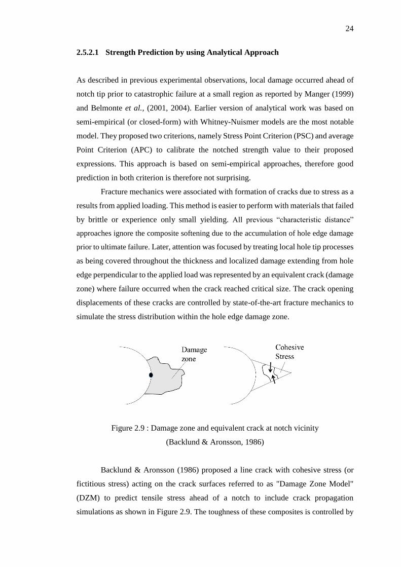
edge perpendicular to the applied load was represented by an equivalent crack (damage
zone) where failure occurred when the crack reached critical size. The crack opening
displacements of these cracks are controlled by state-of-the-art fracture mechanics to
simulate the stress distribution within the hole edge damage zone.
Figure 2.9 : Damage zone and equivalent crack at notch vicinity
(Backlund & Aronsson, 1986)
Backlund & Aronsson (1986) proposed a line crack with cohesive stress (or
fictitious stress) acting on the crack surfaces referred to as "Damage Zone Model"
(DZM) to predict tensile stress ahead of a notch to include crack propagation
simulations as shown in Figure 2.9. The toughness of these composites is controlled by
109
REFERENCES
Abdul Khalil, H. P. S., Bhat, A. H., Jawaid, M., Amouzgar, P., Ridzuan, R., & Said,
M. R. (2010). Cell wall ultrastructure, anatomy, lignin distribution, and chemical
composition of Malaysian cultivated kenaf fiber. Industrial Crops and Products,
31, 113–121.
Abot, J. L., Yasmin, a., Jacobsen, a. J., & Daniel, I. M. (2004). In-plane mechanical,
thermal and viscoelastic properties of a satin fabric carbon/epoxy composite.
Composites Science and Technology, 64, 263–268.
Agarwal, B. L. (1980). Static Strength Prediction of Bolted Joint in Composite
Material. AIAA Journal, 18, 1371–1375.
Ahmad, H. (2012). Finite Element-based Strength Prediction for Notched and
Mechanically Fastened woven fabric Composites. University Of Surrey.
Ahmad, H., Crocombe, a D., & Smith, P. a. (2013). Physically based finite element
strength prediction in notched woven laminates under quasi-static loading.
Plastics, Rubber and Composites, 42, 93–100.
Ahmad, H., Crocombe, a D., & Smith, P. A. (2014a). Strength prediction in CFRP
woven laminate bolted double-lap joints under quasi-static loading using XFEM.
Composites Part A: Applied Science and Manufacturing, 56, 192–220.
Ahmad, H., Crocombe, a. D., & Smith, P. A. (2014b). Strength prediction in CFRP
woven laminate bolted single-lap joints under quasi-static loading using XFEM.
Composites Part A: Applied Science and Manufacturing, 66, 82–93.
Akkerman, R. (2002). On the properties of Quasi-isotropic laminates. Composites Part
B: Engineering, 33, 133–140.
Anuar, H., & Zuraida, A. (2011). Improvement in mechanical properties of reinforced
thermoplastic elastomer composite with kenaf bast fibre. Composites Part B:
110
Engineering, 42, 462–465.
Aronsson, C. G., & Backlund, J. (1986). Tensile Fracture of Laminates with Cracks.
Journal of Composite Materials, 20, 287–307.
Aziz, S. H., & Ansell, M. P. (2004). The effect of alkalization and fibre alignment on
the mechanical and thermal properties of kenaf and hemp bast fibre composites:
Part 1 - polyester resin matrix. Composites Science and Technology, 64, 1219–
1230.
Backlund, J., & Aronsson, C. G. (1986). Tensile Fracture of Laminate with Holes.
Journal of Composite Materials, 20, 259 – 285.
Barenblatt, G. I. (1962). The Mathematical Theory of equilibrium cracks in brittle
fracture. Advance Applied Mechanics, 7, 55–129.
Belmonte, H. M. S., Manger I., C. I. C., Ogin, S. L., Smith, P. A., & Lewin, R. (2001).
Characterisation and modelling of the notched tensile fracture of woven quasi-
isotropic GFRP laminates. Composites Science and Technology, 61, -597.
Belmonte, H. M. S., Ogin, S. L., Smith, P. A., & Lewin, R. (2004). A physically-based
model for the notched strength of woven quasi-isotropic CFRP laminates.
Composites Part A: Applied Science and Manufacturing, 35, 763–778.
Benoit, V., Aucher, J., & Taleb, L. (2009). Influence of temperature on the behavior
of carbon fiber fabrics reinforced PPS laminates. Materials Science and
Engineering A, 517, 51–60.
Benoit, V., Aucher, J., & Taleb, L. (2011). Woven ply thermoplastic laminates under
severe conditions: Notched laminates and bolted joints. Composites Part B:
Engineering, 42, 341–349.
Benoit, V., Aucher, J., & Taleb, L. (2012). Comparative study on the behavior of
woven-ply reinforced thermoplastic or thermosetting laminates under severe
environmental conditions. Materials and Design, 35, 707–719.
Benoit, V., Chabchoub, M., Bouscarrat, D., & Keller, C. (2016). Prediction of the
notched strength of woven-ply Polyphenylene Sulfide thermoplastic composites
at a constant high temperature by a physically-based model. Composite
Structures, 153, 529–537.
111
Benoit, V., & Taleb, L. (2011). About the influence of temperature and matrix ductility
on the behavior of carbon woven-ply PPS or epoxy laminates: Notched and
unnotched laminates. Composites Science and Technology, 71, 998–1007.
Buxton, A., & Baillie, C. (1994). A Study of the Influence of the Enviroment on the
Measurment of Interfacial Properties of Carbon Fiber/Epoxy Resin composites.
Composites, 25, 604–608.
Chang, F. ., & Chang, K. . (1987). A Progressive Damage Model for Laminate
Composites Containing Stress Concentration. Journal of Composite Materials,
21, 809–855.
Chang, F. ., Scott, R. ., & Springer, G. . (1982). Strength of mechanically fastened
composite joints. Composite Materials, 16, 470–494.
Chang, F. ., Springer, G. ., & Scott, R. A. (1984). Failure of composite laminates
containing pin loaded holes-Method of solution. Journal Composite Materials,
18, 255–278.
Collings, T. A. (1977). The strength of bolted joints in multi-directional cfrp laminates.
Composites, 8, 43–55.
Daggumati, S., Van Paepegem, W., Degrieck, J., Praet, T., Verhegghe, B., Xu, J., …
Verpoest, I. (2011). Local strain in a 5-harness satin weave composite under static
tension: Part II - Meso-FE analysis. Composites Science and Technology, 71,
1217–1224.
Dauda, S. M., Ahmad, D., Khalina, A., & Jamarei, O. (2014). Physical and Mechanical
Properties of Kenaf Stems at Varying Moisture Contents. Agriculture and
Agricultural Science Procedia, 2, 370–374.
Dixit, A., & Harlal, S. . (2013). Modeling Techniques for Predicting. Mechanics of
Composite Materials, 49, 1–20.
Economic, P. U. (2010). Tenth Malaysia Plan 2011-2015. Unit Prime Minister’s
Department Putrajaya.
Egan, B., McCarthy, C. T., McCarthy, M. A., & Frizzell, R. M. (2012). Stress analysis
of single-bolt, single-lap, countersunk composite joints with variable bolt-hole
clearance. Composite Structures, 94, 1038–1051.
112
Ekha, J., & Schönb, J. (2005). Effect of secondary bending on strength prediction of
composite, single shear lap joints. Composites Science and Technology, 65, 953–
965.
Eriksson, I., & Aronsson, C. G. (1990). Strength of tensile loaded graphite/epoxy
laminates containing crack, open and filled holes. Journal of Composite
Materials, 24, 456–482.
Esendemir, U. (2008). Failure analysis of woven Glass-epoxy prepreg bolted joint
under difference clamping moment. Advance Composites Letters, 17, 165–175.
Foulk, J. A., Akin, D. E., & Dodd, R. B. (2000). New Low Cost Flax Fibers for
Composites (pp. 2000–01–1133).
George, J., Sreekala, M. S., & Thomas, S. (2001). A review on interface modification
and characterization of natural fiber reinforced plastic composites. Polymer
Engineering & Science, 41, 1471–1485.
Hadi, M., Basri, A., Abdu, A., Junejo, N., & Hamid, H. A. (2014). Journey of kenaf in
Malaysia : A Review. Academic Journal, 9, 458–470.
Hajnalka, H., Racz, I., & Anandjiwala, R. (2008). Development of Hemp Fibre
Reinforced Polypropylene Composite. Journal Thermoplastic Composite
Materials, 21, 165–174.
Harris, C., & Morris, D. (1986). Fracture of thick laminated composite. Experimental
Mechanics, 34–41.
Hart-Smith, & LJ. (1978). Mechanically fastened joints for advanced composites
Phenomelogical consideration and simpel analysis. Dogulas Paper 6748.
Hashin, Z. (1980). Failure Criteria for Unidirectional Fiber Composite. Journal of
Applied Mechanics, 47, 329–334.
Hollaway, L. C. (2010). A review of the present and future utilisation of FRP
composites in the civil infrastructure with reference to their important in-service
properties. Construction and Building Materials, 24, 2419–2445.
Hollman, K. (1996). Failure analysis of bolted composite Joints Exhibiting in plane
failure modes.pdf. Journal of Composite Materials, 30, 358–383.
Joshi, S. . V, Drzal, L. . T., Mohanty, a. . K., & Arora, S. (2004). Are natural fiber

113
composites environmentally superior to glass fiber reinforced composites?
Composites Part A: Applied Science and Manufacturing, 35, 371–376.
Kaldor, A. (1992). Kenaf and Alternate Fiber for Plup and Paper Industries in
Developing and Developed Countries. Journal Composite Material, 75, 141–145.
Karnani, R. (1996). Kenaf-reinforced polypropylene composites. Michigan State
University.
Kontolatis, A. (2000). Failure of Composite Bolted Joints Made from Woven fabric
GFRP Composite. Gulidfore: University of Surrey.
Ku, H., Wang, H., Pattarachaiyakoop, N., & Trada, M. (2011). A review on the tensile
properties of natural fiber reinforced polymer composites. Composites Part B, 42,
856–873.
Li, Y., Hu, C., & Yu, Y. (2008). Interfacial studies of sisal fiber reinforced high density
polyethylene (HDPE) composites. Composites Part A: Applied Science and
Manufacturing, 39, 570–578.
Manger, C. (1999). Failure of Notched Woven GFRP Composites: Damage Analysis
and Strength Modelling. Guildford : University of Surrey.
Marom, G. (1989). Application of Fracture Mechanics to Composite Materials.
Composite Materials Series (Vol. 6). Elsevier Science Publishers B.V. Retrieved
from http://www.sciencedirect.com/science/article/pii/B9780444872869500140
McCarthy, C. T., & McCarthy, M. A. (2005). Three-dimensional finite element
analysis of single-bolt, single-lap composite bolted joints: Part II - Effects of bolt-
hole clearance. Composite Structures, 71, 159–175.
Mccarthy, C. T., Mccarthy, M. A., & Lawlor, V. P. (2005). Progressive damage
analysis of multi-bolt composite joints with variable bolt – hole clearances.
Composites Part B, 36, 290–305.
Mittal, V., Saini, R., & Sinha, S. (2016). Natural fiber-mediated epoxy composites –
A review. Composites Part B: Engineering, 99, 425–435.
Nishino, T., Hirao, K., & Kotera, M. (2006). X-ray diffraction studies on stress transfer
of kenaf reinforced poly(l-lactic acid) composite. Composites Part A: Applied
Science and Manufacturing, 37, 2269–2273.
114
Okutan, B., Aslan, Z., & Karakuzu, R. (2001). A study of the effects of various
geometric parameters on the failure strength of pin-loaded woven-glass-fiber
reinforced epoxy laminate. Composites Science and Technology, 61, 1491–1497.
Olmedo, Á., & Santiuste, C. (2012). On the prediction of bolted single-lap composite
joints. Composite Structures, 94, 2110–2117.
Patel, S. R., & Case, S. W. (2002). Durability of hygrothermally aged graphite/epoxy
woven composite under combined hygrothermal conditions. International
Journal of Fatigue, 24, 1295–1301.
Pinnell, M. (1996). An examination of the effect of composite constitute properties on
the notch strength performance of composite materials. Composites Science and
Technology, 56, 1405–1413.
Pisano, a. a., & Fuschi, P. (2011). Mechanically fastened joints in composite
laminates: Evaluation of load bearing capacity. Composites Part B: Engineering,
42, 949–961.
Saba, N., Paridah, M. T., & Jawaid, M. (2015). Mechanical properties of kenaf fibre
reinforced polymer composite : A review. CONSTRUCTION & BUILDING
MATERIALS, 76, 87–96.
Saiman, M. P., Wahab, M. S., & Wahit, M. U. (2014). The Effect of Fabric Weave on
Tensile Strength of Woven Kenaf Reinforced Unsaturated Polyester Composite.
International Colloqium on Textile Engineering, Fashion, Apparel & Design
2014, 52–56.
Salman, S. D., Sharba, M. J., Leman, Z., Sultan, M. T. H., Ishak, M. R., & Cardona,
F. (2015). Physical, Mechanical, and Morphological Properties of Woven
Kenaf/Polymer Composites Produced Using a Vacuum Infusion Technique.
International Journal of Polymer Science, 2015, 1–11.
Santiuste, C., Barbero, E., & Henar Miguelez, M. (2011). Computational analysis of
temperature effect in composite bolted joints for aeronautical applications.
Journal of Reinforced Plastics and Composites, 30, 3–11.
Schwartz, M. (1996). The Influence of Enviroment Effect. Composite Material
Propertise: Properties, Nodestructive, Testing and Repair, 1, 117–119.
Sellers, T. (1999). Kenaf properties, processing and products. MP. Mississippi State
115
University.
Smith, P. A. (2000). Carbon FiberReinforced Plastics - Properties. Comprehensive
Composite Materials, 107–150.
Tan, S. . (1991). A Progressive Failure Model for Composite Laminates COntaning
Openings. Journal of Composite Materials, 25, 557–577.
Thoppul, S. D., Finegan, J., & Gibson, R. F. (2009). Mechanics of mechanically
fastened joints in polymer-matrix composite structures - A review. Composites
Science and Technology, 69, 301–329.
Tsai, S., & Wu, E. . (1971). A General theory of strength for Anisotropic Material.
Journal of Composite Materials, 5, 58–80.
Tsujimoto, Y., & Wilson, D. (1986). Elasto-Plastic Failure Analysis of Composite
Bolted Joints. Journal of Composite Materials, 20, 236–252.
Wambua, P., Ivens, J., & Verpoest, I. (2003). Natural fibres: can they replace glass in
fibre reinforced plastics? Composites Science and Technology, 63, 1259–1264.
Whitney, J. M., & Nuismer, R. J. (1974). Stress Fracture Criteria for Laminated
Composites Containing Stress Concentrations. Composite Material, 8, 253–265.
Xiao, Y., & Ishikawa, T. (2005). Bearing strength and failure behavior of bolted
composite joints (part II: modeling and simulation). Composites Science and
Technology, 65, 1032–1043.
Yamada, S. ., & Sun, C. . (1978). Analysis of Laminate Strength and Its Distribution.
Journal of Composite Materials, 12, 275–284.
Zaffaroni, G., & Cappelletti, C. (1998). Comparision of Two Acceleration Hot-Wet
Aging Condition of a Glass-Reinforce Epoxy Resin. Composite Material:
Fatigue and Fracture, 7, 233–244.
Zahari, R., Azmee, A. H., Mustapha, F., & Salit, M. S. (2008). Prediction of
Progressive Failure in Woven Glass/Epoxy Composite Laminated Panels. Jurnal
Mekanikal, 80–91.