
A Raspberry Pi-Based Attitude Sensor - arXiv · PDF fileOctober 9, 2014 14:5...
13
October 9, 2014 14:5 Rpi˙attitude˙sensor˙1 A Raspberry Pi-Based Attitude Sensor A. G. Sreejith 1,† , Joice Mathew 1 , Mayuresh Sarpotdar 1 , Rekhesh Mohan 1 , Akshata Nayak 1,2 , Margarita Safonova 1 and Jayant Murthy 1 1 Indian Institute of Astrophysics, Bangalore, India 2 Jain University, Bangalore, India †[email protected] We have developed a lightweight low-cost attitude sensor, based on a Raspberry Pi, built with readily available commercial components. It can be used in experiments where weight and power are constrained, such as in high- altitude lightweight balloon flights. This attitude sensor will be used as a major building block in a closed-loop control system with driver motors to stabilize and point cameras and telescopes for astronomical observations from a balloon-borne payload. Keywords : astronomy, attitude, balloon, stable platform 1. Introduction We have recently begun a program to use low-cost high-altitude balloons for astronomical and atmospheric observations [Nayak et al., 2013]. The main aim is the observations of extended nearby objects (e.g. comets) and of diffuse sources (e.g. zodiacal light or airglow) with wide field of view (FOV) instruments. A key requirement for these observations is accurate and stable pointing in spite of the wind speeds of tens of knots and local turbulence known to exist at altitudes above 30 km [Chingcuanco, 1989], which cause the payload to sway and rotate [Hazen, 1985; Nigro et al., 1985]. We are developing a 3-axis stabilization system to correct for these random motions, where the first step is development of an attitude sensor to determine the pointing direction. An initial pointing accuracy within 0.5 ◦ is sufficient for the wide-field instruments (1–2 degrees) we plan to use. Because we are using lightweight balloons, the total payload weight is limited to less than 6 kg, placing constraints on the sensor size, weight and power. In keeping with our philosophy of developing low-cost balloon experiments, we use only easily sourced commercial components. Different types of attitude sensors have been used in high-altitude balloon flights: star trackers, sun sensors, magnetometers, accelerometers and gyroscopes, each with their own advantages and disadvantages. We have chosen to use a commercial inertial measurement unit (IMU), which combines an accelerometer, a magnetometer and a gyroscope on a single chip. The IMU provides attitude information in terms of Euler angles and quaternions [Bar-Itzhack & Oshman, 1985], which we combine on a Raspberry Pi 1 with the output of a global positioning system (GPS) chip to obtain the celestial coordinates of the pointing direction. The construction of a lightweight compact attitude sensor has become much simpler in recent years due to the replacement of mechanical devices by solid state devices such as, for example, micro- electromechanical systems (MEMS). In this paper we describe the development of a Raspberry Pi-based attitude sensor which uses onboard data fusion, and describe our plan to expand it into a fully-functional 3-axis stabilization system with a star tracker. 2. Hardware and Implementation We have built our attitude sensor around a Raspberry Pi, a small-size single-board computer (SBC) developed by the Raspberry Pi Foundation (technical specifications in Table 1). The Raspberry Pi and 1 http://www.raspberrypi.org 1 arXiv:1412.6444v1 [astro-ph.IM] 19 Dec 2014
Transcript of A Raspberry Pi-Based Attitude Sensor - arXiv · PDF fileOctober 9, 2014 14:5...
October 9, 2014 14:5 Rpi˙attitude˙sensor˙1
A Raspberry Pi-Based Attitude Sensor
A. G. Sreejith1,†, Joice Mathew1, Mayuresh Sarpotdar1, Rekhesh Mohan1, Akshata Nayak1,2, Margarita Safonova1 and
Jayant Murthy1
1 Indian Institute of Astrophysics, Bangalore, India2 Jain University, Bangalore, India
We have developed a lightweight low-cost attitude sensor, based on a Raspberry Pi, built with readily available
commercial components. It can be used in experiments where weight and power are constrained, such as in high-altitude lightweight balloon flights. This attitude sensor will be used as a major building block in a closed-loop
control system with driver motors to stabilize and point cameras and telescopes for astronomical observations
from a balloon-borne payload.
Keywords: astronomy, attitude, balloon, stable platform
1. Introduction
We have recently begun a program to use low-cost high-altitude balloons for astronomical and atmosphericobservations [Nayak et al., 2013]. The main aim is the observations of extended nearby objects (e.g. comets)and of diffuse sources (e.g. zodiacal light or airglow) with wide field of view (FOV) instruments. A keyrequirement for these observations is accurate and stable pointing in spite of the wind speeds of tens ofknots and local turbulence known to exist at altitudes above 30 km [Chingcuanco, 1989], which causethe payload to sway and rotate [Hazen, 1985; Nigro et al., 1985]. We are developing a 3-axis stabilizationsystem to correct for these random motions, where the first step is development of an attitude sensor todetermine the pointing direction. An initial pointing accuracy within 0.5◦ is sufficient for the wide-fieldinstruments (1–2 degrees) we plan to use. Because we are using lightweight balloons, the total payloadweight is limited to less than 6 kg, placing constraints on the sensor size, weight and power. In keepingwith our philosophy of developing low-cost balloon experiments, we use only easily sourced commercialcomponents.
Different types of attitude sensors have been used in high-altitude balloon flights: star trackers, sunsensors, magnetometers, accelerometers and gyroscopes, each with their own advantages and disadvantages.We have chosen to use a commercial inertial measurement unit (IMU), which combines an accelerometer,a magnetometer and a gyroscope on a single chip. The IMU provides attitude information in terms ofEuler angles and quaternions [Bar-Itzhack & Oshman, 1985], which we combine on a Raspberry Pi1 withthe output of a global positioning system (GPS) chip to obtain the celestial coordinates of the pointingdirection. The construction of a lightweight compact attitude sensor has become much simpler in recentyears due to the replacement of mechanical devices by solid state devices such as, for example, micro-electromechanical systems (MEMS). In this paper we describe the development of a Raspberry Pi-basedattitude sensor which uses onboard data fusion, and describe our plan to expand it into a fully-functional3-axis stabilization system with a star tracker.
2. Hardware and Implementation
We have built our attitude sensor around a Raspberry Pi, a small-size single-board computer (SBC)developed by the Raspberry Pi Foundation (technical specifications in Table 1). The Raspberry Pi and
1http://www.raspberrypi.org
1
arX
iv:1
412.
6444
v1 [
astr
o-ph
.IM
] 1
9 D
ec 2
014
October 9, 2014 14:5 Rpi˙attitude˙sensor˙1
2 Sreejith et al.
Table 1. Raspberry Pi Technical Specifications (Source: Raspberry Pi user guide, Raspberry Pi Foundation).
Chip Broadcom BCM2835 full HD multimedia applications processorCPU 700 MHz Low Power ARM176JZ-F applications processorGPU Dual Core VideoCore Multimedia Co-ProcessorMemory 512MB SDRAMEthernet Onboard 10/100 Ethernet connectorUSB 2.0 Dual USB connectorVideo Output HDMI composite RCAAudio Output 3.5mm jack, HDMIOnboard Storage SD, MMC, SDIO card slotWeight 45 gmsPower Rating 700 mA (3.5 W)Operating System RaspbianDimensions 8.6cm x 5.4cm x 1.7cm
similar SBCs (e.g. the Arduino) provide flexible, low-cost platforms to which different devices may beconnected, and which have been used in a number of innovative ways from home automation systems toaeronautical communication devices [Sabastian et al., 2012].
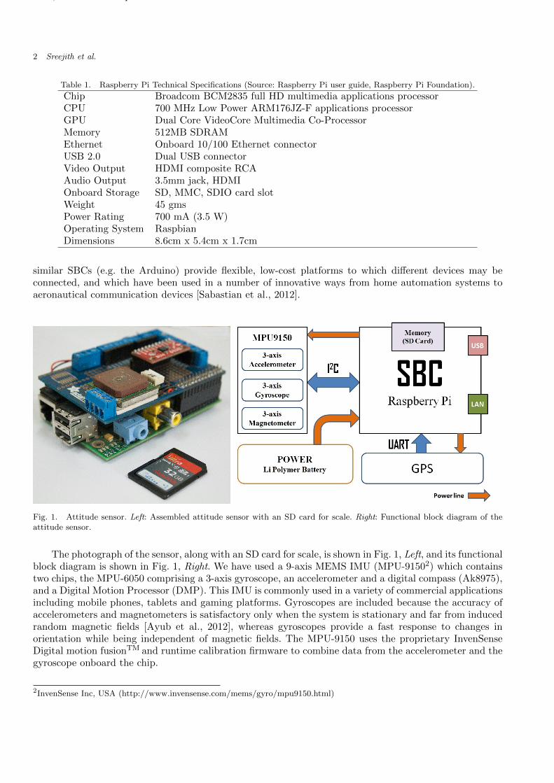
Fig. 1. Attitude sensor. Left: Assembled attitude sensor with an SD card for scale. Right: Functional block diagram of theattitude sensor.
The photograph of the sensor, along with an SD card for scale, is shown in Fig. 1, Left, and its functionalblock diagram is shown in Fig. 1, Right. We have used a 9-axis MEMS IMU (MPU-91502) which containstwo chips, the MPU-6050 comprising a 3-axis gyroscope, an accelerometer and a digital compass (Ak8975),and a Digital Motion Processor (DMP). This IMU is commonly used in a variety of commercial applicationsincluding mobile phones, tablets and gaming platforms. Gyroscopes are included because the accuracy ofaccelerometers and magnetometers is satisfactory only when the system is stationary and far from inducedrandom magnetic fields [Ayub et al., 2012], whereas gyroscopes provide a fast response to changes inorientation while being independent of magnetic fields. The MPU-9150 uses the proprietary InvenSenseDigital motion fusionTM and runtime calibration firmware to combine data from the accelerometer and thegyroscope onboard the chip.
2InvenSense Inc, USA (http://www.invensense.com/mems/gyro/mpu9150.html)

October 9, 2014 14:5 Rpi˙attitude˙sensor˙1
Raspberry Pi based Attitude Sensor 3
The MPU-9150 has user-programmable settings for the gyroscope with ranges of ±250, ±500, ±1000,±1000 and ±2000 ◦/sec (dps), for the accelerometer with ranges of ±2 g, ±4 g, ±8 g and ±16 g, and a singlesetting of ±1200µT range for a compass. For our application the acceleration experienced by the payloaddoes not exceed 2 g as was observed in all of our previous flights, therefore we have chosen the default ±2g settings for the accelerometer. We have selected the default value of ±2000 dps for the gyroscope.
The data from the sensors are digitized by 16-bit analog-to-digital converters (ADCs) for the gyroscope,three 16-bit ADCs for the accelerometer and three 13-bit ADCs for the magnetometer. The data streamfrom the MPU-9150 is fed into the I2C (Inter-Integrated Circuit) port of the Raspberry Pi. This port isa multi-master serial single-ended computer bus, through which low-speed peripherals are attached to themotherboard using bidirectional open drain lines SDA (Serial Data Line) and SCL (Serial Clock) withpull-up resistors. The DMP application processor performs the sensor fusion by integrating the outputfrom the gyroscope and accelerometer, and generates the quaternions (by InvenSense licensed codes insidethe DMP) output which can be read out from the First-In-First-Out (FIFO) registers by our SBC. Sincenow the sensor timing synchronization and sensor fusion computations are carried out by the DMP, thetotal load on Raspberry Pi is reduced.
One of the great advantages of the Raspberry Pi is the extensive library of open-source programsavailable for the platform. We use here the open source code linux-mpu9150 (developed by the Pansentisoftware consultancy and development company3) to read the data from MPU-9150, combine the magne-tometer data with the data from the two other sensors, and calculate the attitude information in terms ofEuler angles.
The Euler angles give the orientation of the sensor relative to an Earth-centered inertial frame (ECI),which we convert to celestial coordinates using the position data (latitude and longitude of the payload)obtained from the GPS sensor (see Appendix A). We have used a 20-channel GPS receiver from iWave4
operating in the L1 frequency band (1575.42 MHz), which gives accuracy better than 10 meters on theground and 20-30 meters in altitude. The data from the GPS sensor is transmitted to the Raspberry Pithrough the Pi’s Universal Asynchronous Receiver/Transmitter (UART) port (Fig. 1, Right) serially atthe rate of 9600 bps. The entire system is powered by a 5 V lithium polymer battery. We have written aprogram to combine the Euler angles with the GPS values and write the output to a file on a SD card. Adetailed description of the algorithm and the program flowchart is presented in Appendix A.
3. Attitude Sensor Calibration
3.1. Initial calibration
The sensor must be calibrated before its first use at a given location by slowly moving it through a rangeof azimuths and elevations. The program linux-mpu9150 finds the direction of the magnetic North fromthe magnetometer values and the local gravitational field vector through the accelerometer output, andthen internally defines a local Earth-centered coordinate system. This calibration is sensitive to the localmagnetic fields and is affected by the presence of nearby ferric objects, for example, the telescope mountand, therefore, has to be repeated for any change of local conditions.
3.2. Gyroscope calibration
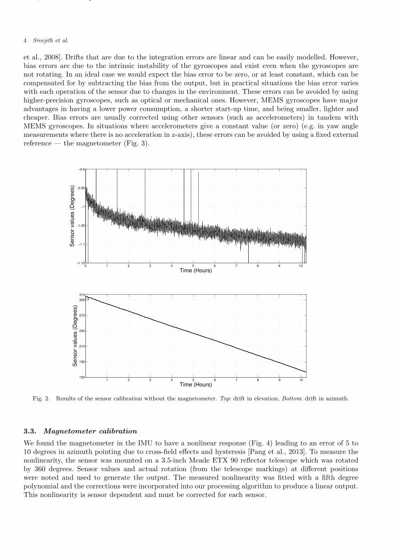
The attitude sensor can operate in two modes: with and without magnetometer. We initially tested thesensor without the magnetometer. The test involved measuring the drift in elevation and azimuth over aperiod of 10 hours. A drift of about one arcminute per hour was observed in elevation values which waswell within our accuracy limits (see Fig. 2, Top). The drift was much higher in azimuth (Fig. 2, Bottom)– almost 150 degrees in 10 hours, which is unacceptable for our applications. These drifts are due to twosources of errors — bias [Groves, 2013] and integration errors [Shiau et al., 2012; Borenstein et al., 2008],that arise because of manufacturing limitations of the MEMS gyroscopes [Shiau et al., 2012; Borenstein
3https://github.com/richards-tech/linux-mpu91504iWave Systems SiRF StarIII GSC3f GPS receiver, iWave Systems, India (http://www.iwavesystems.com)
October 9, 2014 14:5 Rpi˙attitude˙sensor˙1
4 Sreejith et al.
et al., 2008]. Drifts that are due to the integration errors are linear and can be easily modelled. However,bias errors are due to the intrinsic instability of the gyroscopes and exist even when the gyroscopes arenot rotating. In an ideal case we would expect the bias error to be zero, or at least constant, which can becompensated for by subtracting the bias from the output, but in practical situations the bias error varieswith each operation of the sensor due to changes in the environment. These errors can be avoided by usinghigher-precision gyroscopes, such as optical or mechanical ones. However, MEMS gyroscopes have majoradvantages in having a lower power consumption, a shorter start-up time, and being smaller, lighter andcheaper. Bias errors are usually corrected using other sensors (such as accelerometers) in tandem withMEMS gyroscopes. In situations where accelerometers give a constant value (or zero) (e.g. in yaw anglemeasurements where there is no acceleration in z-axis), these errors can be avoided by using a fixed externalreference — the magnetometer (Fig. 3).
0 1 2 3 4 5 6 7 8 9 10−1.15
−1.1
−1.05
−1
−0.95
−0.9
Time (Hours)
Sensor
valu
es (
Degre
es)
1 2 3 4 5 6 7 8 9 10150
180
210
240
270
300
310
Time (Hours)
Sensor
valu
es (
Degre
es)
Fig. 2. Results of the sensor calibration without the magnetometer. Top: drift in elevation, Bottom: drift in azimuth.
3.3. Magnetometer calibration
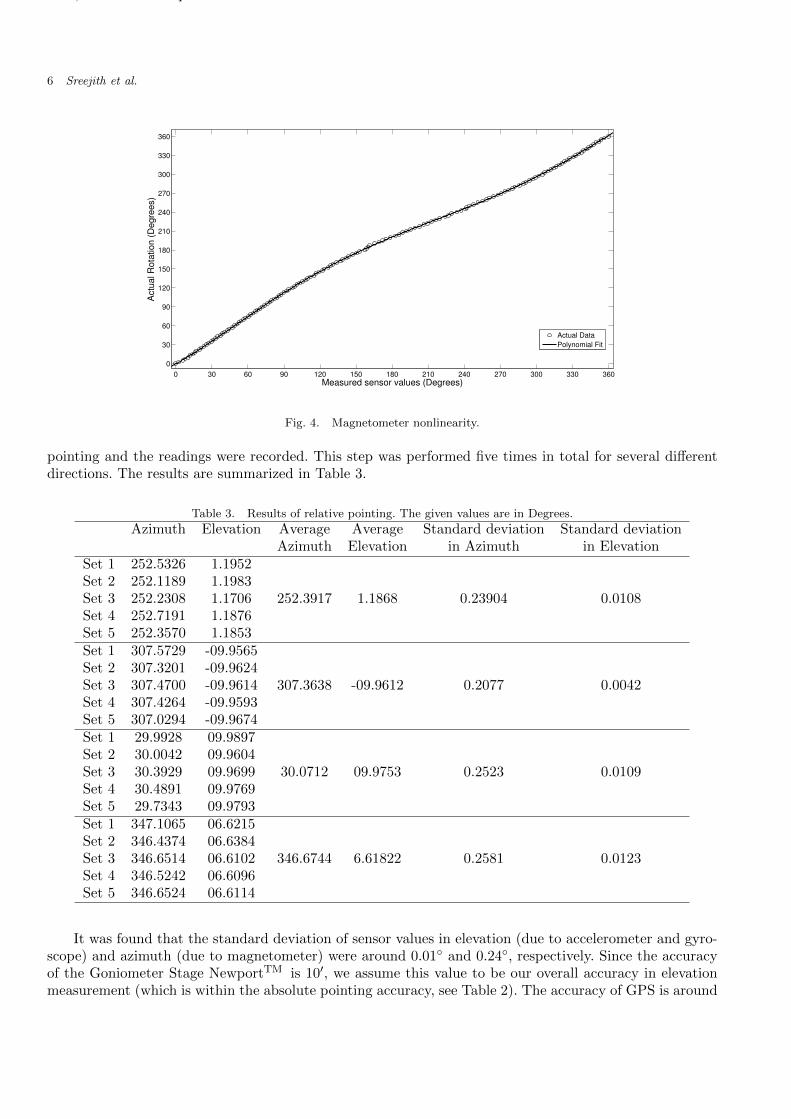
We found the magnetometer in the IMU to have a nonlinear response (Fig. 4) leading to an error of 5 to10 degrees in azimuth pointing due to cross-field effects and hysteresis [Pang et al., 2013]. To measure thenonlinearity, the sensor was mounted on a 3.5-inch Meade ETX 90 reflector telescope which was rotatedby 360 degrees. Sensor values and actual rotation (from the telescope markings) at different positionswere noted and used to generate the output. The measured nonlinearity was fitted with a fifth degreepolynomial and the corrections were incorporated into our processing algorithm to produce a linear output.This nonlinearity is sensor dependent and must be corrected for each sensor.
October 9, 2014 14:5 Rpi˙attitude˙sensor˙1
Raspberry Pi based Attitude Sensor 5
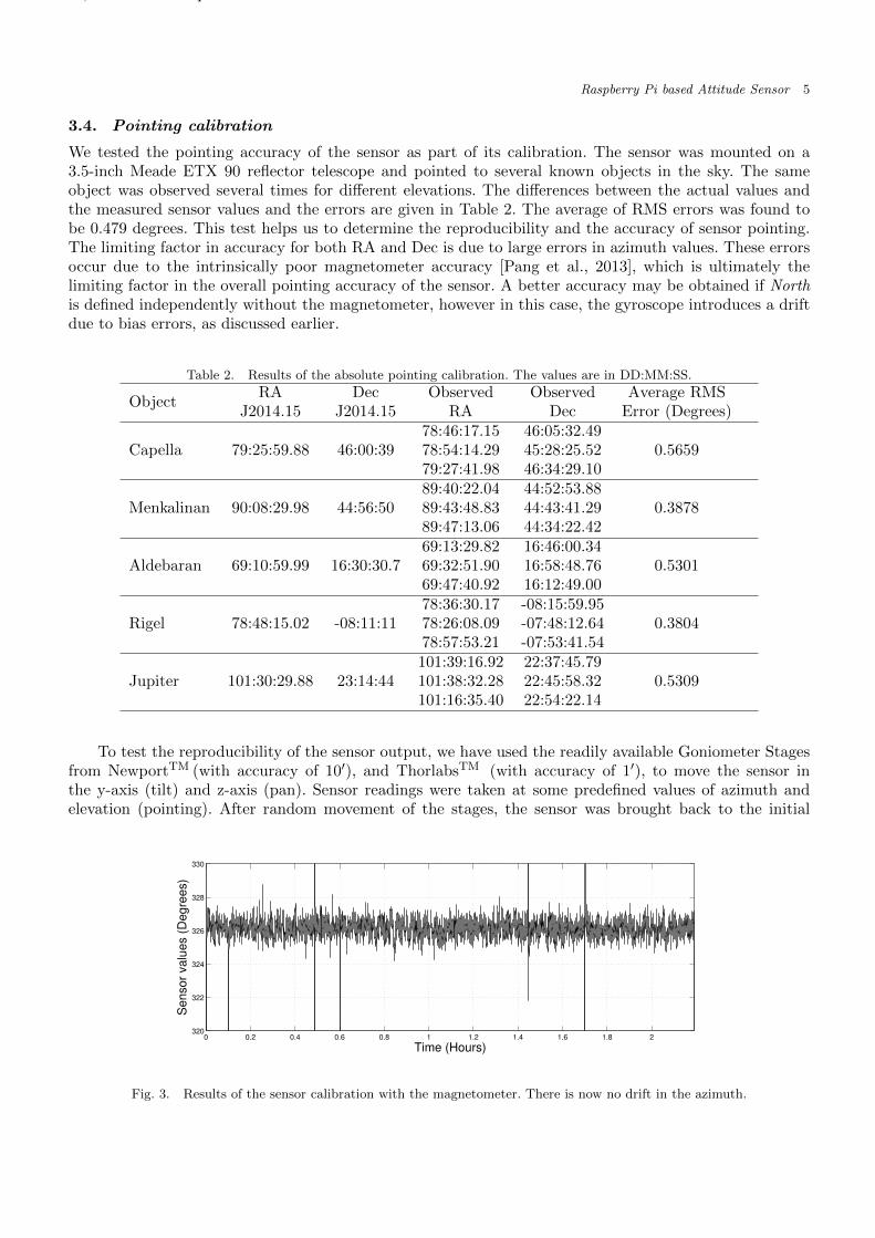
3.4. Pointing calibration
We tested the pointing accuracy of the sensor as part of its calibration. The sensor was mounted on a3.5-inch Meade ETX 90 reflector telescope and pointed to several known objects in the sky. The sameobject was observed several times for different elevations. The differences between the actual values andthe measured sensor values and the errors are given in Table 2. The average of RMS errors was found tobe 0.479 degrees. This test helps us to determine the reproducibility and the accuracy of sensor pointing.The limiting factor in accuracy for both RA and Dec is due to large errors in azimuth values. These errorsoccur due to the intrinsically poor magnetometer accuracy [Pang et al., 2013], which is ultimately thelimiting factor in the overall pointing accuracy of the sensor. A better accuracy may be obtained if Northis defined independently without the magnetometer, however in this case, the gyroscope introduces a driftdue to bias errors, as discussed earlier.
Table 2. Results of the absolute pointing calibration. The values are in DD:MM:SS.
ObjectRA Dec Observed Observed Average RMS
J2014.15 J2014.15 RA Dec Error (Degrees)
Capella 79:25:59.88 46:00:3978:46:17.15 46:05:32.49
0.565978:54:14.29 45:28:25.5279:27:41.98 46:34:29.10
Menkalinan 90:08:29.98 44:56:5089:40:22.04 44:52:53.88
0.387889:43:48.83 44:43:41.2989:47:13.06 44:34:22.42
Aldebaran 69:10:59.99 16:30:30.769:13:29.82 16:46:00.34
0.530169:32:51.90 16:58:48.7669:47:40.92 16:12:49.00
Rigel 78:48:15.02 -08:11:1178:36:30.17 -08:15:59.95
0.380478:26:08.09 -07:48:12.6478:57:53.21 -07:53:41.54
Jupiter 101:30:29.88 23:14:44101:39:16.92 22:37:45.79
0.5309101:38:32.28 22:45:58.32101:16:35.40 22:54:22.14
To test the reproducibility of the sensor output, we have used the readily available Goniometer Stagesfrom NewportTM (with accuracy of 10′), and ThorlabsTM (with accuracy of 1′), to move the sensor inthe y-axis (tilt) and z-axis (pan). Sensor readings were taken at some predefined values of azimuth andelevation (pointing). After random movement of the stages, the sensor was brought back to the initial
0 0.2 0.4 0.6 0.8 1 1.2 1.4 1.6 1.8 2320
322
324
326
328
330
Time (Hours)
Sensor
valu
es (
Degre
es)
Fig. 3. Results of the sensor calibration with the magnetometer. There is now no drift in the azimuth.
October 9, 2014 14:5 Rpi˙attitude˙sensor˙1
6 Sreejith et al.
0 30 60 90 120 150 180 210 240 270 300 330 360
0
30
60
90
120
150
180
210
240
270
300
330
360
Measured sensor values (Degrees)
Actu
al R
ota
tion (
Degre
es)
Actual Data
Polynomial Fit
Fig. 4. Magnetometer nonlinearity.
pointing and the readings were recorded. This step was performed five times in total for several differentdirections. The results are summarized in Table 3.
Table 3. Results of relative pointing. The given values are in Degrees.
Azimuth Elevation Average Average Standard deviation Standard deviationAzimuth Elevation in Azimuth in Elevation
Set 1 252.5326 1.1952
252.3917 1.1868 0.23904 0.0108Set 2 252.1189 1.1983Set 3 252.2308 1.1706Set 4 252.7191 1.1876Set 5 252.3570 1.1853Set 1 307.5729 -09.9565
307.3638 -09.9612 0.2077 0.0042Set 2 307.3201 -09.9624Set 3 307.4700 -09.9614Set 4 307.4264 -09.9593Set 5 307.0294 -09.9674Set 1 29.9928 09.9897
30.0712 09.9753 0.2523 0.0109Set 2 30.0042 09.9604Set 3 30.3929 09.9699Set 4 30.4891 09.9769Set 5 29.7343 09.9793Set 1 347.1065 06.6215
346.6744 6.61822 0.2581 0.0123Set 2 346.4374 06.6384Set 3 346.6514 06.6102Set 4 346.5242 06.6096Set 5 346.6524 06.6114
It was found that the standard deviation of sensor values in elevation (due to accelerometer and gyro-scope) and azimuth (due to magnetometer) were around 0.01◦ and 0.24◦, respectively. Since the accuracyof the Goniometer Stage NewportTM is 10′, we assume this value to be our overall accuracy in elevationmeasurement (which is within the absolute pointing accuracy, see Table 2). The accuracy of GPS is around
October 9, 2014 14:5 Rpi˙attitude˙sensor˙1
Raspberry Pi based Attitude Sensor 7
10′′ and introduces much less error to the attitude sensor.
3.5. Thermal Dependence of the sensor
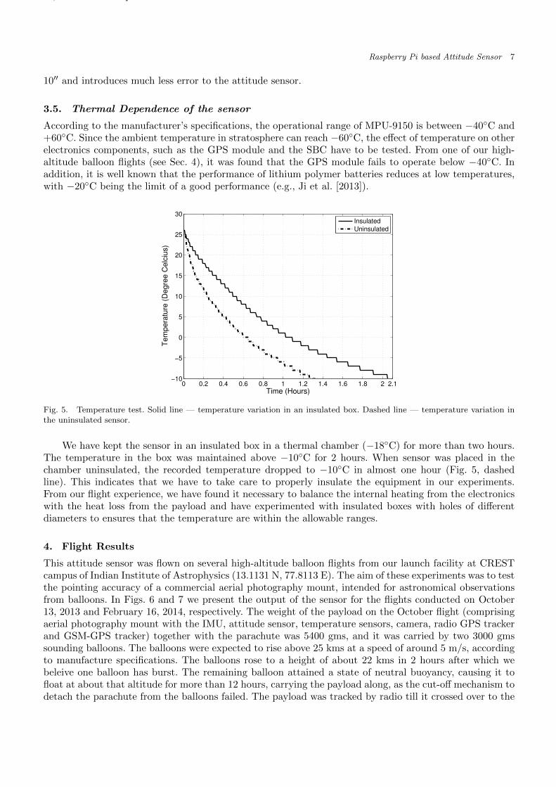
According to the manufacturer’s specifications, the operational range of MPU-9150 is between −40◦C and+60◦C. Since the ambient temperature in stratosphere can reach −60◦C, the effect of temperature on otherelectronics components, such as the GPS module and the SBC have to be tested. From one of our high-altitude balloon flights (see Sec. 4), it was found that the GPS module fails to operate below −40◦C. Inaddition, it is well known that the performance of lithium polymer batteries reduces at low temperatures,with −20◦C being the limit of a good performance (e.g., Ji et al. [2013]).
0 0.2 0.4 0.6 0.8 1 1.2 1.4 1.6 1.8 2 2.1−10
−5
0
5
10
15
20
25
30
Time (Hours)
Te
mp
era
ture
(D
eg
ree
Ce
lciu
s)
Insulated
Uninsulated
Fig. 5. Temperature test. Solid line — temperature variation in an insulated box. Dashed line — temperature variation inthe uninsulated sensor.
We have kept the sensor in an insulated box in a thermal chamber (−18◦C) for more than two hours.The temperature in the box was maintained above −10◦C for 2 hours. When sensor was placed in thechamber uninsulated, the recorded temperature dropped to −10◦C in almost one hour (Fig. 5, dashedline). This indicates that we have to take care to properly insulate the equipment in our experiments.From our flight experience, we have found it necessary to balance the internal heating from the electronicswith the heat loss from the payload and have experimented with insulated boxes with holes of differentdiameters to ensures that the temperature are within the allowable ranges.
4. Flight Results
This attitude sensor was flown on several high-altitude balloon flights from our launch facility at CRESTcampus of Indian Institute of Astrophysics (13.1131 N, 77.8113 E). The aim of these experiments was to testthe pointing accuracy of a commercial aerial photography mount, intended for astronomical observationsfrom balloons. In Figs. 6 and 7 we present the output of the sensor for the flights conducted on October13, 2013 and February 16, 2014, respectively. The weight of the payload on the October flight (comprisingaerial photography mount with the IMU, attitude sensor, temperature sensors, camera, radio GPS trackerand GSM-GPS tracker) together with the parachute was 5400 gms, and it was carried by two 3000 gmssounding balloons. The balloons were expected to rise above 25 kms at a speed of around 5 m/s, accordingto manufacture specifications. The balloons rose to a height of about 22 kms in 2 hours after which webeleive one balloon has burst. The remaining balloon attained a state of neutral buoyancy, causing it tofloat at about that altitude for more than 12 hours, carrying the payload along, as the cut-off mechanism todetach the parachute from the balloons failed. The payload was tracked by radio till it crossed over to the

October 9, 2014 14:5 Rpi˙attitude˙sensor˙1
8 Sreejith et al.
Arabian sea, around 400 kms west of the launch site. The payload was later partially recovered by Indianfishermen from the Arabian sea. While the aerial photography mount with its data was lost, the attitudesensor data was recovered and analyzed. We present the results of the analysis in Fig. 6. Oscillations inazimuth values (Fig. 6, Top) indicate that the payload experienced spinning motion during the entire flightwith a frequency of 50 degrees in 2–3 minutes, and the elevation values (Fig. 6, Bottom) indicate that thepayload was experiencing swinging motion with frequency below 2 degrees for the entire flight.
0 0.5 1 1.5 2 2.5 3 3.5 4 4.50
60
120
180
240
300
360
Time (Hours)
Azim
uth
(D
eg
ree
s)
0 0.5 1 1.5 2 2.5 3 3.5 4 4.5−50
−30
−10
10
30
50
Time (Hours)
Ele
va
tio
n (
De
gre
es)
Launch
Launch
Fig. 6. Attitude sensor data from balloon flight on October 13, 2013. X-axis is time of the balloon flight in hours. Top:Azimuth values, Bottom: Elevation values. The sensor was switched on at 0.0 hours and the balloon was released at 0.2 hours.The large variation in both azimuth and elevation values till 0.2 hours are due to the handling of the payload on the ground.
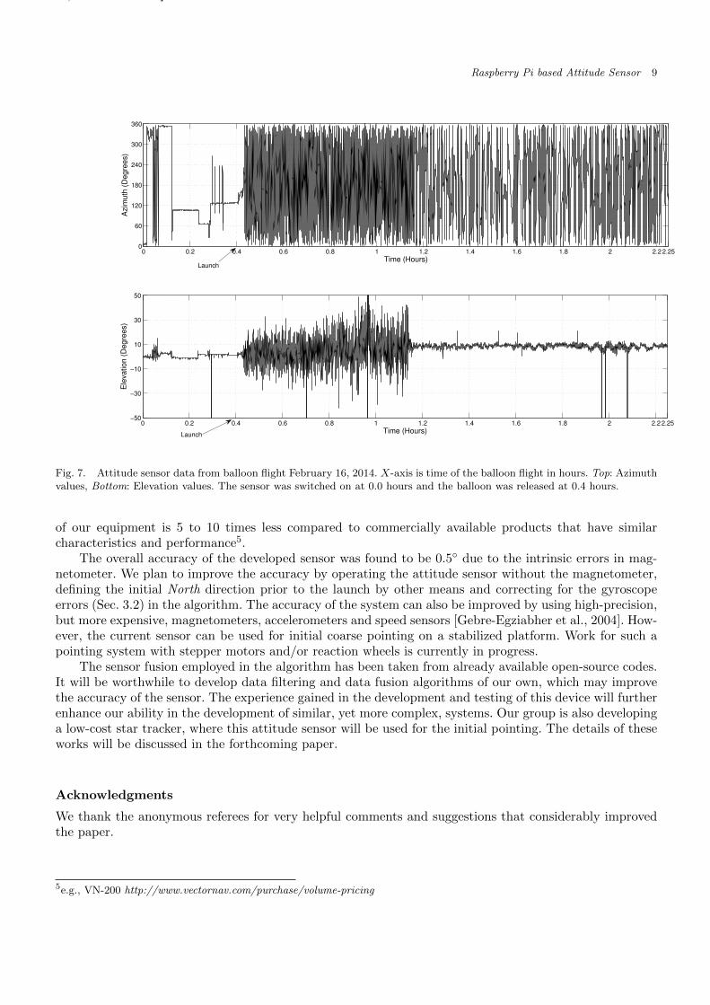
The payload on the February flight (UV spectrograph, attitude sensor, temperature sensors, camera,radio-GPS tracker and GSM-GPS tracker) together with the parachute weighed 5400 gms and was carriedby three 2000 gms sounding balloons. The balloons reached the maximum height of 26.9 kms in 2.5 hours.The balloons burst at that altitude and the payload was successfully recovered around 100 km from thelaunch site. There was much more turbulence on the second flight (Fig. 7) mainly because of the use ofthree balloons instead of two and a stormy weather. The change in frequency of swinging and swaying ofthe payload as it crossed the tropospheric boundary at around 1.2 hours from the start is clearly visible inFig. 7.
The attitude sensor was flown on these flights in order to test its working in flight conditions and todetermine the movement of the payload due to winds. A stabilization platform for astronomical observationsis currently in development by our group and eventually the attitude sensor will be flown with it to testits pointing accuracy.
5. Conclusions and Future Work
We have described the development and calibration of a low-cost attitude sensor which can be built withreadily available commercial components. The attitude sensor described in this paper can be used as abuilding block in a closed-loop pointing and stabilization platform for balloon-borne payloads. The cost
October 9, 2014 14:5 Rpi˙attitude˙sensor˙1
Raspberry Pi based Attitude Sensor 9
0 0.2 0.4 0.6 0.8 1 1.2 1.4 1.6 1.8 2 2.2 2.250
60
120
180
240
300
360
Time (Hours)
Azim
uth
(D
egre
es)
0 0.2 0.4 0.6 0.8 1 1.2 1.4 1.6 1.8 2 2.2 2.25−50
−30
−10
10
30
50
Time (Hours)
Ele
vation (
Degre
es)
Launch
Launch
Fig. 7. Attitude sensor data from balloon flight February 16, 2014. X-axis is time of the balloon flight in hours. Top: Azimuthvalues, Bottom: Elevation values. The sensor was switched on at 0.0 hours and the balloon was released at 0.4 hours.
of our equipment is 5 to 10 times less compared to commercially available products that have similarcharacteristics and performance5.
The overall accuracy of the developed sensor was found to be 0.5◦ due to the intrinsic errors in mag-netometer. We plan to improve the accuracy by operating the attitude sensor without the magnetometer,defining the initial North direction prior to the launch by other means and correcting for the gyroscopeerrors (Sec. 3.2) in the algorithm. The accuracy of the system can also be improved by using high-precision,but more expensive, magnetometers, accelerometers and speed sensors [Gebre-Egziabher et al., 2004]. How-ever, the current sensor can be used for initial coarse pointing on a stabilized platform. Work for such apointing system with stepper motors and/or reaction wheels is currently in progress.
The sensor fusion employed in the algorithm has been taken from already available open-source codes.It will be worthwhile to develop data filtering and data fusion algorithms of our own, which may improvethe accuracy of the sensor. The experience gained in the development and testing of this device will furtherenhance our ability in the development of similar, yet more complex, systems. Our group is also developinga low-cost star tracker, where this attitude sensor will be used for the initial pointing. The details of theseworks will be discussed in the forthcoming paper.
Acknowledgments
We thank the anonymous referees for very helpful comments and suggestions that considerably improvedthe paper.
5e.g., VN-200 http://www.vectornav.com/purchase/volume-pricing
October 9, 2014 14:5 Rpi˙attitude˙sensor˙1
10 Sreejith et al.
Appendices
Appendix A Description of the software
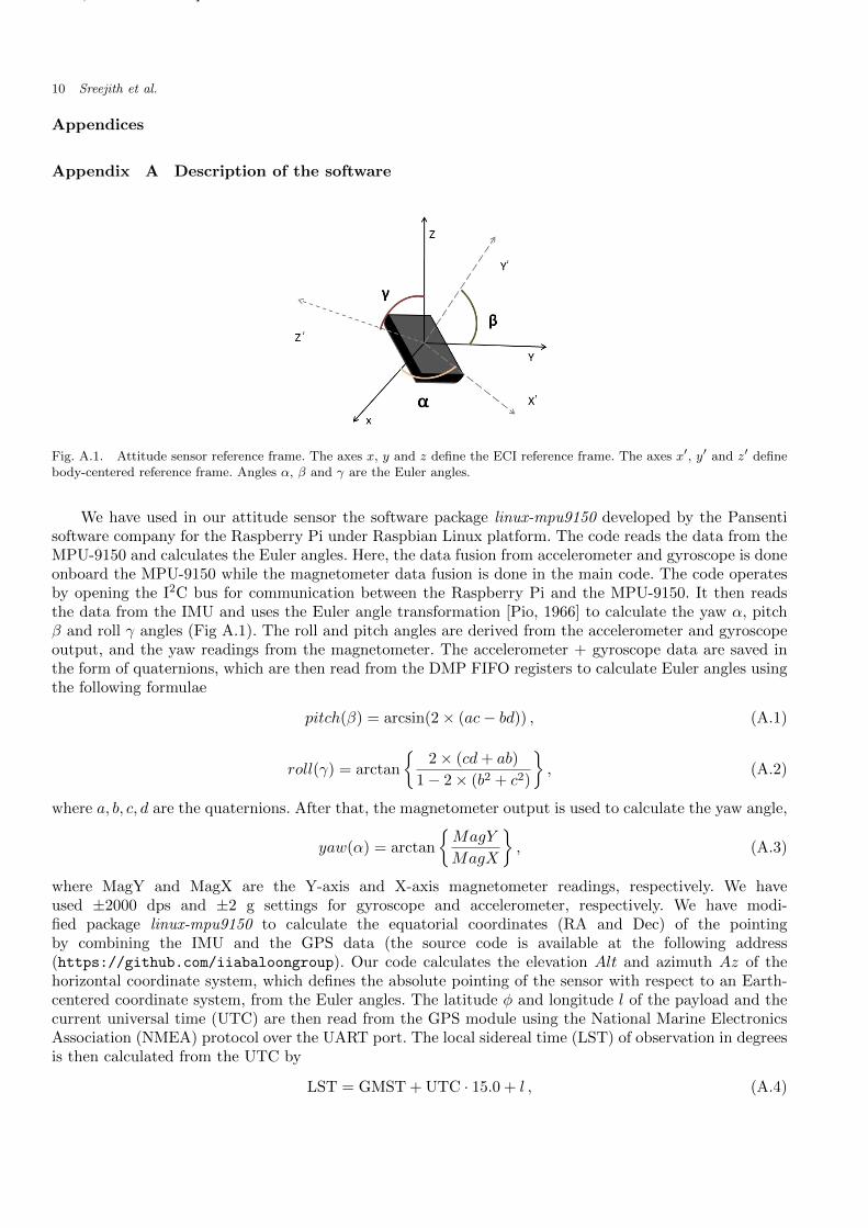
Fig. A.1. Attitude sensor reference frame. The axes x, y and z define the ECI reference frame. The axes x′, y′ and z′ definebody-centered reference frame. Angles α, β and γ are the Euler angles.
We have used in our attitude sensor the software package linux-mpu9150 developed by the Pansentisoftware company for the Raspberry Pi under Raspbian Linux platform. The code reads the data from theMPU-9150 and calculates the Euler angles. Here, the data fusion from accelerometer and gyroscope is doneonboard the MPU-9150 while the magnetometer data fusion is done in the main code. The code operatesby opening the I2C bus for communication between the Raspberry Pi and the MPU-9150. It then readsthe data from the IMU and uses the Euler angle transformation [Pio, 1966] to calculate the yaw α, pitchβ and roll γ angles (Fig A.1). The roll and pitch angles are derived from the accelerometer and gyroscopeoutput, and the yaw readings from the magnetometer. The accelerometer + gyroscope data are saved inthe form of quaternions, which are then read from the DMP FIFO registers to calculate Euler angles usingthe following formulae
pitch(β) = arcsin(2× (ac− bd)) , (A.1)
roll(γ) = arctan
{2× (cd+ ab)
1− 2× (b2 + c2)
}, (A.2)
where a, b, c, d are the quaternions. After that, the magnetometer output is used to calculate the yaw angle,
yaw(α) = arctan
{MagY
MagX
}, (A.3)
where MagY and MagX are the Y-axis and X-axis magnetometer readings, respectively. We haveused ±2000 dps and ±2 g settings for gyroscope and accelerometer, respectively. We have modi-fied package linux-mpu9150 to calculate the equatorial coordinates (RA and Dec) of the pointingby combining the IMU and the GPS data (the source code is available at the following address(https://github.com/iiabaloongroup). Our code calculates the elevation Alt and azimuth Az of thehorizontal coordinate system, which defines the absolute pointing of the sensor with respect to an Earth-centered coordinate system, from the Euler angles. The latitude φ and longitude l of the payload and thecurrent universal time (UTC) are then read from the GPS module using the National Marine ElectronicsAssociation (NMEA) protocol over the UART port. The local sidereal time (LST) of observation in degreesis then calculated from the UTC by
LST = GMST + UTC · 15.0 + l , (A.4)
October 9, 2014 14:5 Rpi˙attitude˙sensor˙1
Raspberry Pi based Attitude Sensor 11
where GMST (Greenwich Mean Sidereal Time) in degrees is
289.9404 + 4.70935× 10⁵ · d+ 356.0470 + 0.9856002585 · d+ 180 , (A.5)
and quantity d is calculated from the date information YYYY-MM-DD as
d = 367 ·YYYY− 7
4
(Y Y Y Y +
MM + 9
12
)+
275 ·MM
9+DD − 730530.0 +
UTC
24. (A.6)
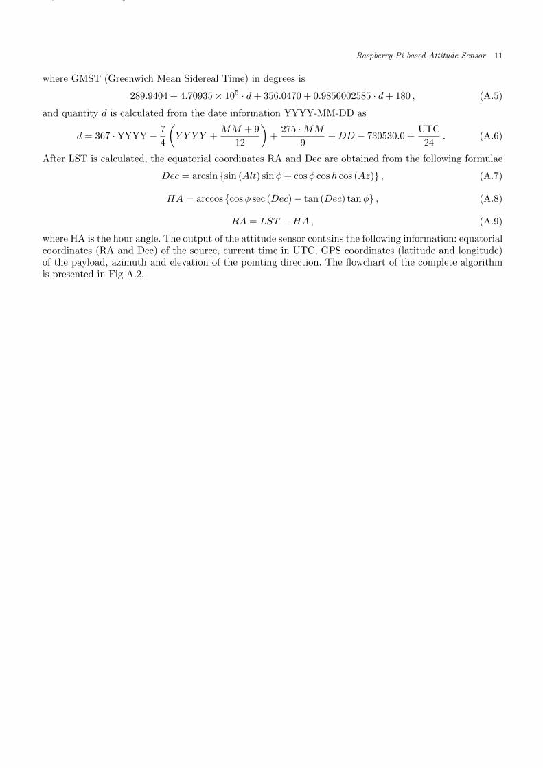
After LST is calculated, the equatorial coordinates RA and Dec are obtained from the following formulae
Dec = arcsin {sin (Alt) sinφ+ cosφ cosh cos (Az)} , (A.7)
HA = arccos {cosφ sec (Dec)− tan (Dec) tanφ} , (A.8)
RA = LST −HA , (A.9)
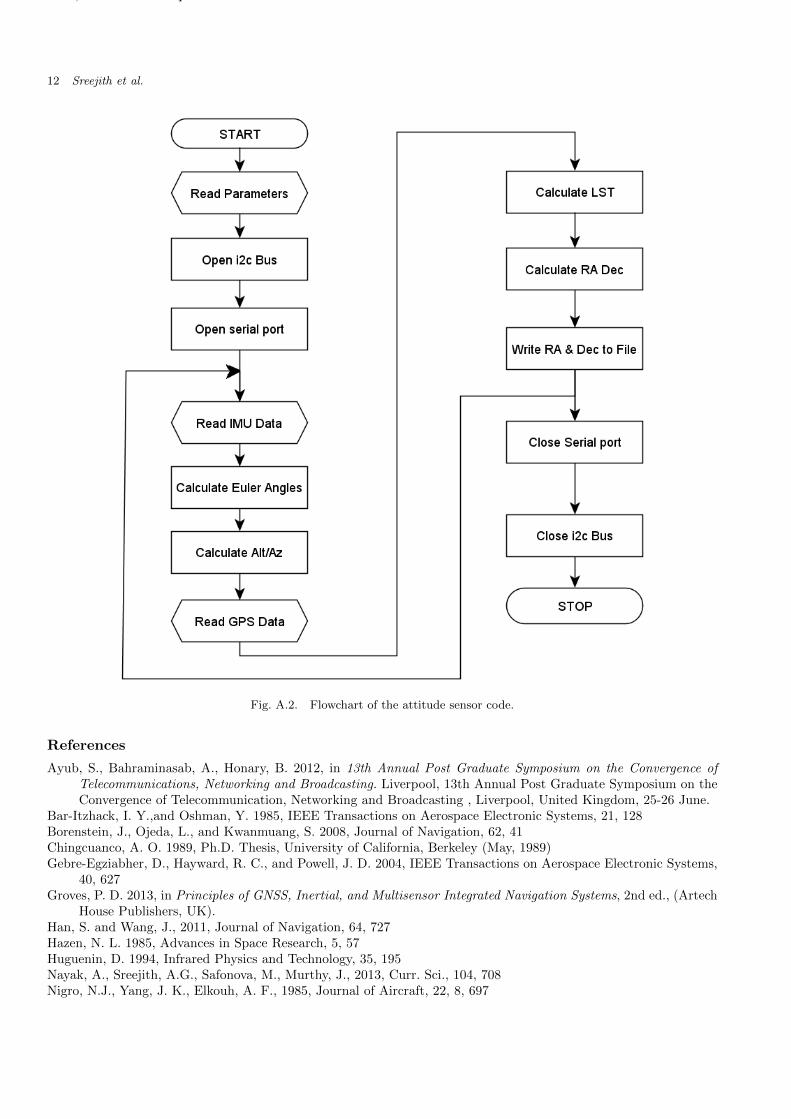
where HA is the hour angle. The output of the attitude sensor contains the following information: equatorialcoordinates (RA and Dec) of the source, current time in UTC, GPS coordinates (latitude and longitude)of the payload, azimuth and elevation of the pointing direction. The flowchart of the complete algorithmis presented in Fig A.2.
October 9, 2014 14:5 Rpi˙attitude˙sensor˙1
12 Sreejith et al.
Fig. A.2. Flowchart of the attitude sensor code.
References
Ayub, S., Bahraminasab, A., Honary, B. 2012, in 13th Annual Post Graduate Symposium on the Convergence ofTelecommunications, Networking and Broadcasting. Liverpool, 13th Annual Post Graduate Symposium on theConvergence of Telecommunication, Networking and Broadcasting , Liverpool, United Kingdom, 25-26 June.
Bar-Itzhack, I. Y.,and Oshman, Y. 1985, IEEE Transactions on Aerospace Electronic Systems, 21, 128Borenstein, J., Ojeda, L., and Kwanmuang, S. 2008, Journal of Navigation, 62, 41Chingcuanco, A. O. 1989, Ph.D. Thesis, University of California, Berkeley (May, 1989)Gebre-Egziabher, D., Hayward, R. C., and Powell, J. D. 2004, IEEE Transactions on Aerospace Electronic Systems,
40, 627Groves, P. D. 2013, in Principles of GNSS, Inertial, and Multisensor Integrated Navigation Systems, 2nd ed., (Artech
House Publishers, UK).Han, S. and Wang, J., 2011, Journal of Navigation, 64, 727Hazen, N. L. 1985, Advances in Space Research, 5, 57Huguenin, D. 1994, Infrared Physics and Technology, 35, 195Nayak, A., Sreejith, A.G., Safonova, M., Murthy, J., 2013, Curr. Sci., 104, 708Nigro, N.J., Yang, J. K., Elkouh, A. F., 1985, Journal of Aircraft, 22, 8, 697

October 9, 2014 14:5 Rpi˙attitude˙sensor˙1
Raspberry Pi based Attitude Sensor 13
Pang, H., Chen, D., Pan, M., et al. 2013, IEEE Transactions on Magnetics, 49, 5011Pio, R.L., 1966, IEEE Trans on Automatic Contro, AC11 (4), 707Sabastian, T. A., Guarddin, G., Abi, R. N., Mufti, H. M., 2012, International Conference on Advanced Computer
Science and Information Systems (ICACSIS), 83Shiau, J.K., Huang, C., Chang, M., 2012, Journal of Applied Science and Engineering, 15, 239Ji, Y., Zhang, Y., Wang, C.-Y., 2013, J. Electrochem. Soc., 160, A636