
A. R. F. - Hobbico, Inc. - largest U.S. distributor of...
32
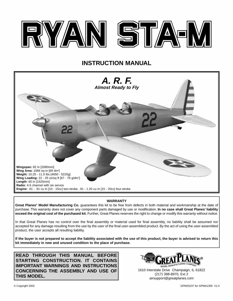
WARRANTY Great Planes ® Model Manufacturing Co. guarantees this kit to be free from defects in both material and workmanship at the date of purchase. This warranty does not cover any component parts damaged by use or modification. In no case shall Great Planes’ liability exceed the original cost of the purchased kit. Further, Great Planes reserves the right to change or modify this warranty without notice. In that Great Planes has no control over the final assembly or material used for final assembly, no liability shall be assumed nor accepted for any damage resulting from the use by the user of the final user-assembled product. By the act of using the user-assembled product, the user accepts all resulting liability. If the buyer is not prepared to accept the liability associated with the use of this product, the buyer is advised to return this kit immediately in new and unused condition to the place of purchase. READ THROUGH THIS MANUAL BEFORE STARTING CONSTRUCTION. IT CONTAINS IMPORTANT WARNINGS AND INSTRUCTIONS CONCERNING THE ASSEMBLY AND USE OF THIS MODEL. GPMZ0237 for GPMA1355 V1.0 © Copyright 2002 1610 Interstate Drive Champaign, IL 61822 (217) 398-8970, Ext 2 [email protected] INSTRUCTION MANUAL A. R. F. Almost Ready to Fly Wingspan: 82 in [2080mm] Wing Area: 1066 sq in [69 dm 2 ] Weight: 10.25 - 11.5 lbs [4650 - 5220g] Wing Loading: 22 - 25 oz/sq ft [67 - 76 g/dm 2 ] Length: 60 in [1525mm] Radio: 4-5 channel with six servos Engine: .61 - .91 cu in [10 - 15cc] two-stroke, .91 - 1.20 cu in [15 - 20cc] four-stroke
Transcript of A. R. F. - Hobbico, Inc. - largest U.S. distributor of...
WARRANTYGreat Planes® Model Manufacturing Co. guarantees this kit to be free from defects in both material and workmanship at the date ofpurchase. This warranty does not cover any component parts damaged by use or modification. In no case shall Great Planes’ liabilityexceed the original cost of the purchased kit. Further, Great Planes reserves the right to change or modify this warranty without notice.
In that Great Planes has no control over the final assembly or material used for final assembly, no liability shall be assumed noraccepted for any damage resulting from the use by the user of the final user-assembled product. By the act of using the user-assembledproduct, the user accepts all resulting liability.
If the buyer is not prepared to accept the liability associated with the use of this product, the buyer is advised to return thiskit immediately in new and unused condition to the place of purchase.
READ THROUGH THIS MANUAL BEFORESTARTING CONSTRUCTION. IT CONTAINSIMPORTANT WARNINGS AND INSTRUCTIONSCONCERNING THE ASSEMBLY AND USE OFTHIS MODEL.
GPMZ0237 for GPMA1355 V1.0© Copyright 2002
1610 Interstate Drive Champaign, IL 61822(217) 398-8970, Ext 2
INSTRUCTION MANUAL
A. R. F.Almost Ready to Fly
Wingspan: 82 in [2080mm]Wing Area: 1066 sq in [69 dm2]Weight: 10.25 - 11.5 lbs [4650 - 5220g]Wing Loading: 22 - 25 oz/sq ft [67 - 76 g/dm2]Length: 60 in [1525mm]Radio: 4-5 channel with six servosEngine: .61 - .91 cu in [10 - 15cc] two-stroke, .91 - 1.20 cu in [15 - 20cc] four-stroke
INTRODUCTION................................................................2IMAA...................................................................................2Scale competition ...............................................................3SAFETY PRECAUTIONS ..................................................3DECISIONS YOU MUST MAKE ........................................4Radio Equipment................................................................4Engine Recommendations .................................................4Spinner Adapter Kit ............................................................4ADDITIONAL ITEMS REQUIRED .....................................4Hardware and Accessories ................................................4Adhesives and Building Supplies .......................................4Optional Supplies and Tools...............................................5IMPORTANT BUILDING NOTES.......................................5KIT CONTENTS.................................................................6ORDERING REPLACEMENT PARTS...............................7TIGHTEN THE COVERING................................................8ASSEMBLE THE WING.....................................................8Hinge the Ailerons..............................................................8Hook Up the Ailerons .........................................................9Join the Wing......................................................................9Mount the Landing Gear ..................................................10ASSEMBLE THE FUSELAGE.........................................12Mount the Stabilizer and Fin ............................................12Mount the Servos .............................................................15Hook Up the Rudder ........................................................17Hook Up the Elevators .....................................................18Mount the Tailgear............................................................20Mount the Engine .............................................................21Mount the Cowl ................................................................22Finish the Radio Installation .............................................24SCALE DETAILS .............................................................24Mount the Wing Struts......................................................24Finish the Cockpits ...........................................................25Apply the Decals ..............................................................27PREPARE THE MODEL FOR FLYING............................27Set the Control Throws.....................................................27Balance the Model Laterally.............................................28Balance the Model (C.G.).................................................28Identify Your Model ...........................................................29Charge the Batteries ........................................................29Balance Propellers ...........................................................29CHECKLIST.....................................................................29FINAL PREPARATIONS..................................................30Ground Check ..................................................................30Range Check....................................................................30ENGINE SAFETY PRECAUTIONS .................................30AMA SAFETY CODE ......................................................30General.............................................................................30Radio Control ...................................................................31FLYING.............................................................................31Takeoff ..............................................................................31Flight.................................................................................31Landing ..............................................................Back CoverWindscreen Template .....................................Back Cover
Congratulations and thank you for purchasing the GreatPlanes Ryan STA-M ARF. We at Great Planes R&D werepleased with the appearance and performance of theoriginal red, white and black civilian Ryan STA and are justas pleased with this military “M” version. In fact, a couple ofminor improvements make this plane our best ARF yet.Although not intended to be an all-out scale model, theRyan's classic design and two-cockpit layout make ittempting for enthusiastic modelers to spend a few extrahours adding even more details (such as cockpit controls,flying wires, panel lines, etc.).
When it's time to fly your STA-M, you'll be as pleased withits performance as you are with its appearance. During testflying, it flew so well that we had to actually try to make badlandings! And every time the Ryan went up, local R/C clubmembers stopped what they were doing to watch this modelfly. The STA-M's greatest attribute–and what you can expectwhen you get your model in the air–is its nostalgicgracefulness. Make sure you have plenty of fuel in your fieldbox because when it's time to fly, you'll be needing it.
For the latest technical updates or instruction manualcorrections to the Ryan STA-M, visit the web site listed belowand select the Great Planes Ryan STA-M ARF. If there is newtechnical information or changes to this model, a “technotice” box will appear in the upper left corner of the page.
http://www.greatplanes.com/airplanes/index.html
The Great Planes Ryan STA-M is an excellent sport-scalemodel and is eligible to fly in IMAA (International MiniatureAircraft Association) events. The IMAA is an organizationthat promotes non-competitive flying of giant-scale models.If you plan to attend an IMAA event, contact the IMAA for acopy of the IMAA Safety Code at the address or telephonenumber below.
IMAA 205 S. Hilldale Road
Salina, KS 67401(913) 823-5569
IMAA Information
INTRODUCTIONTABLE OF CONTENTS
2
Though the Great Planes Ryan STA-M is an ARF and maynot have the same level of detail as an “all-out” scratch-builtmodel, it is a scale model none-the-less and is thereforeeligible to compete in the Fun Scale class in AMAcompetition (we receive many favorable reports from thosewho fly Great Planes ARFs in scale competition!). In FunScale, the “builder of the model” rule does not apply. Toreceive the five points for scale documentation, the only proofrequired that a full size aircraft of this type in thispaint/markings scheme did exist is a single sheet such as akit box cover from a plastic model, a photo, or a profilepainting, etc. If the photo is in black and white, other writtendocumentation of color must be provided. Contact the AMAfor a rule book with full details.
If you would like photos of the full-size Ryan STA-M for scaledocumentation, or if you would like to study the photos toadd more scale details, photo packs are available from:
Bob's Aircraft Documentation3114 Yukon Ave
Costa Mesa, CA 92626
Telephone: (714) 979-8058Fax: (714) 979-7279
e-mail: www.bobsairdoc.com
1. Your Ryan STA-M should not be considered a toy, butrather a sophisticated, working model that functions verymuch like a full-size airplane. Because of its performancecapabilities, the Ryan STA-M, if not assembled and operatedcorrectly, could possibly cause injury to yourself orspectators and damage to property.
2. You must assemble the model according to theinstructions. Do not alter or modify the model, as doing somay result in an unsafe or unflyable model. In a few casesthe instructions may differ slightly from the photos. In thoseinstances the written instructions should be considered as correct.
3. You must take time to build straight, true and strong.
4. You must use an R/C radio system that is in first-classcondition and a correctly sized engine and components (fueltank, wheels, etc.) throughout the building process.
5. You must correctly install all R/C and other components sothat the model operates correctly on the ground and in the air.
6. You must check the operation of the model before everyflight to insure that all equipment is operating and that themodel has remained structurally sound. Be sure to checkclevises or other connectors often and replace them if theyshow any signs of wear or fatigue.
7. If you are not already an experienced R/C pilot, youshould fly the model only with the help of a competent,experienced R/C pilot.
8. While this kit has been flight tested to exceed normal use,if the plane will be used for extremely high stress flying, suchas racing, the modeler is responsible for taking steps toreinforce the high stress points.
9. WARNING: The cowl and wheel pants included in this kitare made of fiberglass, the fibers of which may cause eye,skin and respiratory tract irritation. Never blow into a part toremove fiberglass dust, as the dust will blow back into youreyes. Always wear safety goggles, a particle mask andrubber gloves when grinding, drilling and sanding fiberglassparts. Vacuum the parts and work area thoroughly afterworking with fiberglass parts.
Remember:Take your time and follow the instructions toend up with a well-built model that is straight and true.
If you have not flown a low-wing model before, werecommend that you get the assistance of an experiencedpilot in your R/C club for your first flights. If you're not amember of a club, your local hobby shop has informationabout clubs in your area whose membership includesexperienced pilots.
In addition to joining an R/C club, we strongly recommend youjoin the AMA (Academy of Model Aeronautics). AMAmembership is required to fly at AMA sanctioned clubs.Thereare over 2,500 AMA chartered clubs across the country.Among other benefits, the AMA provides insurance to itsmembers who fly at sanctioned sites and events. Additionally,training programs and instructors are available at AMA clubsites to help you get started the right way. Contact the AMA atthe address or toll-free phone number below:
Academy of Model Aeronautics5151 East Memorial Drive
Muncie, IN 47302-9252Tele. (800) 435-9262Fax (765) 741-0057
Or via the Internet at: http://www.modelaircraft.org
We, as the kit manufacturer, provide you with a top qualitykit and instructions, but ultimately the quality and flyabilityof your finished model depends on how you build it;therefore, we cannot in any way guarantee theperformance of your completed model and norepresentations are expressed or implied as to theperformance or safety of your completed model.
PROTECT YOUR MODEL, YOURSELF& OTHERS...FOLLOW THESE
IMPORTANT SAFETY PRECAUTIONS
Scale Competition
3

Though technically the Ryan STA-M is considered a “giant-scale” model, it does not require the same “heavy-duty” equipment as other truly giant planes.The only “heavy-duty” equipment suggested for this model is three servosthat have 50 oz.-in. [3.3 kg-cm] or more of torque (one forthe rudder and two for the elevators). The ailerons andthrottle may be operated by standard servos.
Because the Ryan STA-M uses dual elevator servos andbecause the servos must move in opposite directions (due tothe way they are mounted in the fuse), they cannot beconnected with a “Y” connector (unless you have a “reverse”servo). Therefore, to fly the Ryan, a radio system capable ofelectronic servo mixing is required, so that one of theelevator servos can be reversed. If you do not have a radiowith programmable mixing, the Futaba® SR-10 SynchronizedServo Reverser (FUTM4150) may be used. When bothelevator servos are connected to this device, they operate inopposite directions. The Synchronized Servo Reverser iscompatible with most popular radio systems.
A receiver battery with a capacity of at least 1000 mAh isalso recommended for this model.
There are several engines that will work well in the Ryan STA-M ARF.The official engine size recommendation range is.61 - .91 cu in [10.0 - 15.0cc] two-stroke or .91 - 1.20 cu in[15.0 - 20.0cc] four-stroke. If an engine in the upper end of thesize range is selected, remember that this is a scale modelthat is intended be flown in a scale manner at scale speeds,so prudent throttle management must be practiced. Ourprototype, powered by an O.S.® MAX .91 FS with a 14 x 6prop, flew smoothly and most scale-like at about 3/4 throttle.Refer to your engine manufacturer's recommendations for thecorrect size propeller. Note: With the O.S. MAX .91 four-strokeused in this model, the O.S. “in” type exhaust header pipe(OSMG2624) was used to position the muffler so an exhausthole did not have to be cut in the cowl.
This kit includes a 2-3/4" aluminum spinner with a 10-32spinner bolt. Due to the variety of engines that may be usedon the Ryan, an adapter kit for mounting the spinner is notincluded with this kit and must be purchased separately. Forthe O.S. .61 SF, SX and other two-stroke engines with a5/16"-24 crankshaft thread purchase Spinner Adapter Kit#GPMQ4584. For the O.S. .91 to 1.20 four-strokes and other
four-strokes with a 5/16"-24 crankshaft thread purchaseSpinner Adapter Kit #GPMQ4588. If neither of these adapterkits will suit your engine, another brand of adapter kit (thatincludes both the prop nut and the spacer ring for the backplate of the spinner - such as Tru-Turn) must be purchased.
In addition to the items listed in the “Decisions You MustMake” section, following is the list of hardware andaccessories required to finish the Ryan. Order numbers areprovided in parentheses.
❏ (2) 24" [610mm] Servo extensions for ailerons(HCAM2200 or HCAM2721 for Futaba®)
❏ (1) 6" [150mm] Servo extension for aileron (HCAM2000or HCAM2701 for Futaba)
❏ (1) “Y” connector for ailerons (FUTM4130 for Futaba)❏ Suitable propeller and spare propellers❏ Medium Fuel Tubing (GPMQ4131)❏ Switch & Charge Jack Mounting Set (GPMM1000)❏ Fuel filler valve for glow fuel (GPMQ4160)❏ R/C foam padding (1/4" [6mm] HCAQ1000, or 1/2"
[13mm] HCAQ1050)❏ (2) Williams Bros. #62500 1/4-scale Standard pilots
(WBRQ2625)❏ Olive Drab paint for cockpit and paint for pilots❏ Model Products #021 Remote glow plug adapter
(MODP1221)❏ 1/4" [6mm] Kwik Stripe silver striping tape (GPMQ1244)❏ #64 rubber bands (for mounting fuel tank)
In addition to common household tools and hobby tools, thisis the “short list” of the most important items required to buildthe Ryan. Great Planes Pro™ CA and Epoxy glue are recommended.
❏ 1/2 oz. Thin CA (GPMR6002)❏ 1/2 oz. Medium CA (GPMR6008)❏ CA Applicator Tips (HCAR3780)❏ 30-Minute Epoxy (GPMR6047)❏ Milled Fiberglass (GPMR6165)❏ Threadlocker (GPMR6060)❏ 50" [1270mm] of K&S #801 Kevlar thread (K+SR4575) or
non-elastic monofilament line for stab alignment❏ Builders Triangle Set (HCAR0480) (for fin alignment)❏ Masking Tape (TOPR8018)❏ Silver solder (GPMR8070)❏ Small metal file❏ English size drill bits: 1/16", #48 (or 5/64"), 3/32", #36 (or
7/64"), 1/8", #29 (or 9/64"), 5/32", 3/16", 7/32", 17/64" (or
Adhesives and Building Supplies
Hardware and Accessories
ADDITIONAL ITEMS REQUIRED
Spinner Adapter Kit
Engine Recommendations
Radio Equipment
DECISIONS YOU MUST MAKE
4

1/4") -or- Metric size drill bits: 1.6mm, #48 (or 2mm),2.4mm, #36 (or 2.8mm), 3.2mm, #29 (or 3.6mm), 4mm,4.8mm, 5.6mm, 6.7 (or 6.4mm),
❏ 6-32 tap (or Great Planes 6-32 tap and drill set with #36drill - GPMR8102)
❏ 8-32 tap (or Great Planes 8-32 tap and drill set with #29drill - GPMR8103)
❏ 3/16" brass tube❏ Coverite™ 21st Century® sealing iron (COVR2700) ❏ Coverite™ 21st Century iron cover (COVR2702)❏ Coverite™ 21st Century trim seal iron (COVR2750)❏ Denatured Alcohol (for epoxy clean up)
Here is a list of optional items mentioned in the manual thatwill help you assemble the Ryan.
❏ CA Debonder (GPMR6039)❏ CA Activator (GPMR6034)❏ 6-Minute Epoxy (GPMR6045)❏ Microballoons (TOPR1090)❏ Epoxy Brushes (GPMR8060)❏ Mixing Sticks (GPMR8055)❏ Hobby Knife (HCAR0105), #11 Blades (HCAR0211)❏ Easy-Touch™ Bar Sander (GPMR6170 or similar)❏ Felt-Tip Marker (TOPQ2510)❏ Rotary tool such as a Dremel®
❏ Reinforced cut-off wheel (GPMR8020)❏ Curved Tip Canopy Scissors for Trimming Plastic Parts
(HCAR0667)❏ Dead Center™ Engine Mount Hole Locator (GPMR8130)❏ Great Planes AccuThrow™ Deflection Gauge (for
measuring control throws, GPMR2405)❏ Flat Black MonoKote® film for optional anti-glare panel (6'
roll - TOPQ0508)❏ 5/32" brass tube
• There are two types of screws used in this kit:
Sheet metal screws are designated by a number and alength. For example #6 x 3/4" [19mm]
This is a number six screw that is 3/4" [19mm] long.
Machine screws are designated by a number, threads perinch and a length. For example 4-40 x 3/4" [19mm]
This is a number four screw that is 3/4" [19mm] longwith forty threads per inch.
• When you see the term test fit in the instructions, itmeans that you should first position the part on theassembly without using any glue, then slightly modify orcustom fit the part as necessary for the best fit.
• Whenever the term glue is written you should rely uponyour experience to decide what type of glue to use. When aspecific type of adhesive works best for that step, theinstructions will make a recommendation.
• Whenever just epoxy is specified you may use either30-minute (or 45-minute) epoxy or 6-minute epoxy. When30-minute epoxy is specified it is highly recommended thatyou use only 30-minute (or 45-minute) epoxy, because youwill need the working time and/or the additional strength.
• Photos and sketches are placed before the step theyrefer to. Frequently you can study photos in following stepsto get another view of the same parts.
• The Ryan STA-M is factory-covered with Top FliteMonoKote film. Should repairs ever be required, MonoKotecan be patched with additional MonoKote purchasedseparately. MonoKote is packaged in six-foot rolls, but somehobby shops also sell it by the foot. If only a small piece ofMonoKote is needed for a minor patch, perhaps a fellowmodeler would give you some. MonoKote is applied with amodel airplane covering iron, but in an emergency a regulariron could be used. A roll of MonoKote includes fullinstructions for application. Following are the colors used onthis model and order numbers for six foot rolls.
Aluminum (TOPQ0205)Cub Yellow (TOPQ0220)True Red (TOPQ0227)
Insignia Blue (TOPQ0207)White (TOPQ0204)
IMPORTANT BUILDING NOTES
Optional Supplies and Tools
5
6
24
2416
4
17
1822
23 21
7
7
1
3
5
2
1
13
12
19
6
14
11
1015
8
9
20
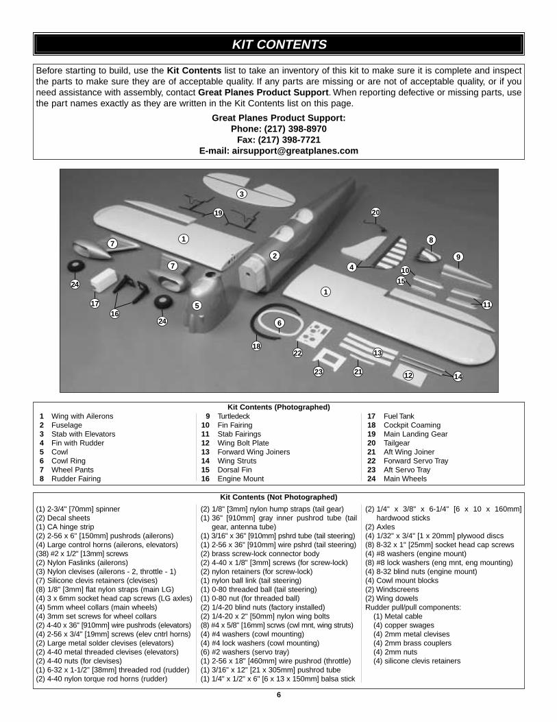
1 Wing with Ailerons2 Fuselage3 Stab with Elevators4 Fin with Rudder5 Cowl6 Cowl Ring7 Wheel Pants8 Rudder Fairing
9 Turtledeck10 Fin Fairing11 Stab Fairings12 Wing Bolt Plate13 Forward Wing Joiners14 Wing Struts15 Dorsal Fin16 Engine Mount
17 Fuel Tank18 Cockpit Coaming19 Main Landing Gear20 Tailgear21 Aft Wing Joiner22 Forward Servo Tray23 Aft Servo Tray24 Main Wheels
(1) 2-3/4" [70mm] spinner(2) Decal sheets(1) CA hinge strip(2) 2-56 x 6" [150mm] pushrods (ailerons)(4) Large control horns (ailerons, elevators)(38) #2 x 1/2" [13mm] screws(2) Nylon Faslinks (ailerons)(3) Nylon clevises (ailerons - 2, throttle - 1)(7) Silicone clevis retainers (clevises)(8) 1/8" [3mm] flat nylon straps (main LG)(4) 3 x 6mm socket head cap screws (LG axles)(4) 5mm wheel collars (main wheels)(4) 3mm set screws for wheel collars(2) 4-40 x 36" [910mm] wire pushrods (elevators)(4) 2-56 x 3/4" [19mm] screws (elev cntrl horns)(2) Large metal solder clevises (elevators)(2) 4-40 metal threaded clevises (elevators)(2) 4-40 nuts (for clevises)(1) 6-32 x 1-1/2" [38mm] threaded rod (rudder)(2) 4-40 nylon torque rod horns (rudder)
(2) 1/8" [3mm] nylon hump straps (tail gear)(1) 36" [910mm] gray inner pushrod tube (tail
gear, antenna tube)(1) 3/16" x 36" [910mm] pshrd tube (tail steering)(1) 2-56 x 36" [910mm] wire pshrd (tail steering)(2) brass screw-lock connector body(2) 4-40 x 1/8" [3mm] screws (for screw-lock)(2) nylon retainers (for screw-lock)(1) nylon ball link (tail steering)(1) 0-80 threaded ball (tail steering)(1) 0-80 nut (for threaded ball)(2) 1/4-20 blind nuts (factory installed)(2) 1/4-20 x 2" [50mm] nylon wing bolts(8) #4 x 5/8" [16mm] scrws (cwl mnt, wing struts)(4) #4 washers (cowl mounting)(4) #4 lock washers (cowl mounting)(6) #2 washers (servo tray)(1) 2-56 x 18" [460mm] wire pushrod (throttle)(1) 3/16" x 12" [21 x 305mm] pushrod tube(1) 1/4" x 1/2" x 6" [6 x 13 x 150mm] balsa stick
(2) 1/4" x 3/8" x 6-1/4" [6 x 10 x 160mm]hardwood sticks
(2) Axles(4) 1/32" x 3/4" [1 x 20mm] plywood discs(8) 8-32 x 1" [25mm] socket head cap screws(4) #8 washers (engine mount)(8) #8 lock washers (eng mnt, eng mounting)(4) 8-32 blind nuts (engine mount)(4) Cowl mount blocks(2) Windscreens(2) Wing dowelsRudder pull/pull components:
(1) Metal cable(4) copper swages(4) 2mm metal clevises(4) 2mm brass couplers(4) 2mm nuts(4) silicone clevis retainers
Kit Contents (Photographed)
Kit Contents (Not Photographed)
Before starting to build, use the Kit Contents list to take an inventory of this kit to make sure it is complete and inspectthe parts to make sure they are of acceptable quality. If any parts are missing or are not of acceptable quality, or if youneed assistance with assembly, contact Great Planes Product Support. When reporting defective or missing parts, usethe part names exactly as they are written in the Kit Contents list on this page.
Great Planes Product Support:Phone: (217) 398-8970
Fax: (217) 398-7721E-mail: [email protected]
KIT CONTENTS

7
To order replacement parts for the Great Planes Ryan STA-M ARF, use the order numbers in the Replacement Parts Listthat follows. Replacement parts are available only as listed. Not all parts are available separately (an aileron cannot bepurchased separately, but is only available with the wing kit). Replacement parts are not available from Product Support,but can be purchased from hobby shops or mail order/Internet order firms. Hardware items (screws, nuts, bolts) are alsoavailable from these outlets. If you need assistance locating a dealer to purchase parts, visit www.greatplanes.com andclick on “Where to Buy.” If this kit is missing parts, contact Great Planes Product Support.
Replacement Parts List
Order Number Description How to PurchaseMissing pieces ................................................Contact Product SupportInstruction manual...........................................Contact Product SupportFull-size plans .................................................Not availableKit parts listed below.......................................Hobby Supplier
GPMA2280 ...........Wing Kit (R&L wing panels, R&L ailerons, hinge strip, 3 pc. ply forward wingjoiner, ply aft wing joiner, (2) wing dowels, wing bolt plate.)
GPMA2281 ...........Fuselage Kit (Fuselage, forward and aft servo trays, (4) hardwood cowlmounting blocks, (2) cockpit coaming, (2) 1/4" x 3/8" x 6-3/8" [7 x 10 x165mm] hardwood forward servo mount rails, 1/4" x 1/2" x 6" [6 x 13 x150mm] balsa rudder pushrod tube support, (2) hardwood wing strutmounting blocks.)
GPMA2282 ...........Tail Set (Fin & rudder, stab & elevators, hinge strip.)GPMA2283 ...........Cowl (Fiberglass cowl, plywood cowl ring, (4) ply cowl discs.)GPMA2284 ...........Windscreen Set (2)GPMA2205 ...........Main Landing Gear Set (L&R)GPMA2286 ...........Wheel Pants (L&R)GPMA2287 ...........Wing Strut Set (2)GPMA2288 ...........Axle Set ((2) axles, (4) wheel collars, screws, wrenches)GPMA2289 ...........Rudder Pull-Pull Set (Braided rudder cable, (4) threaded brass couplers,
(4) metal clevises, (4) 2mm nuts, (4) copper swages.)GPMA2290 ...........Decal Sheet Set (2 sheets)GPMA2291 ...........Plastic Parts Set (Turtledeck, stab & fin fairings, R&L rudder fairing.)GPMA2292 ...........Tailgear Set w/Wheel
ORDERING REPLACEMENT PARTS
0" 1" 2" 3" 4" 5" 6" 7"
0 10 20 30 40 50 60 70 80 90 100 110 120 130 140 150 160 170 180
Inch Scale
Metric Scale
To convert inches to millimeters, multiply inches by 25.4

1. If you have not done so already, remove the major partsof the kit from the box (wings, fuse, wheel pants, cowl, tailparts, etc.) and inspect them for damage. If any parts aredamaged or missing, contact Product Support at theaddress or telephone number listed on page 6.
2. Remove the masking tape and separate the ailerons fromthe wing, the rudder from the fin, and the elevators from thestab. If necessary, use a covering iron with a covering sockon high heat to tighten the covering. Apply pressure oversheeted areas to thoroughly bond the covering to thewood. Hint: Poke three or four pin holes in the coveringbetween the “ribs” in the tail surfaces and ailerons. This willallow air to escape to fully tighten the covering.
Do the right aileron first.
❏ ❏ 1. Locate the hinge slots in the right wing and the rightaileron. Cut a small strip of covering from each slot.
❏ ❏ 2. Drill a 3/32" [2.4mm] hole 1/2" [13mm] deep in thecenter of the slots. For the best result, use a high-speed toolsuch as a Dremel. Insert a #11 knife blade into the slots,working it back and forth a few times to clean the slots out.
❏ ❏ 3. Cut four 3/4" x 1" [19 x 25mm] hinges from thesupplied CA hinge strip.
❏ ❏ 4. Test fit the aileron to the wing with the hinges. If thehinge slots are too tight, remove the hinges and use a #11blade to slightly open the slots. If necessary, insert a pinthrough the center of the hinges so they remain centeredwhen joining the aileron to the wing.
❏ ❏ 5. With the aileron joined to the wing, remove any pinsused to center the hinges. Be certain there is a small gapbetween the leading edge of the aileron and the wing–justenough to slip a piece of paper through or to see light through.
❏ ❏ 6. Apply six drops of thin CA to both sides of all thehinges. Wait a few seconds between drops to allow thehinge slots to fully absorb the CA.
❏ 7. Join the left aileron to the left wing panel the same way.
THIN CA
1"
1"
3/4"
DRILL A 3/32" HOLE1/2" DEEP, IN CENTER
OF HINGE SLOT
AWAY FROM THE SLOTCUT THE COVERING
Hinge the Ailerons
ASSEMBLE THE WING
TIGHTEN THE COVERING
8
Start with the right aileron.
❏ ❏ 1. Cut the covering from the right aileron servo mountin the bottom of the wing. Hint: Cut the covering 1/8" [3mm]inside the edges, then use a trim iron to seal the covering tothe edges.
❏ ❏ 2. Connect a servo extension cord to the aileron servowire. Secure the connection with vinyl tape, heat shrinktubing, or special clips suitable for that purpose.
❏ ❏ 3. Tie the end of the string that is taped inside thewing to the end of the servo wire. Pull the wire through.Note: If something happens to the string such as it breaksor it cannot be located, don't worry. Tie another piece ofstring to the servo wire and tie a weight (such as a wheelcollar) to the other end of the string. Place the wing on endand drop the weight down through the holes in the ribs. Pullthe end of the string out of the hole in the middle of the wing.
Refer to this photo for the following two steps.
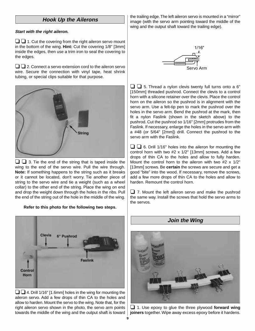
❏ ❏ 4. Drill 1/16" [1.6mm] holes in the wing for mounting theaileron servo. Add a few drops of thin CA to the holes andallow to harden. Mount the servo to the wing. Note that, for theright aileron servo shown in the photo, the servo arm pointstowards the middle of the wing and the output shaft is toward
the trailing edge.The left aileron servo is mounted in a “mirror”image (with the servo arm pointing toward the middle of thewing and the output shaft toward the trailing edge).
❏ ❏ 5. Thread a nylon clevis twenty full turns onto a 6"[150mm] threaded pushrod. Connect the clevis to a controlhorn with a silicone retainer over the clevis. Place the controlhorn on the aileron so the pushrod is in alignment with theservo arm. Use a felt-tip pen to mark the pushrod over theholes in the servo arm. Bend the pushrod at the mark, thenfit a nylon Faslink (shown in the sketch above) to thepushrod. Cut the pushrod so 1/16" [2mm] protrudes from theFaslink. If necessary, enlarge the holes in the servo arm witha #48 (or 5/64" [2mm]) drill. Connect the pushrod to theservo arm with the Faslink.
❏ ❏ 6. Drill 1/16" holes into the aileron for mounting thecontrol horn with two #2 x 1/2" [13mm] screws. Add a fewdrops of thin CA to the holes and allow to fully harden.Mount the control horn to the aileron with two #2 x 1/2"[13mm] screws. Be certain the screws are secure and get agood “bite” into the wood. If necessary, remove the screws,add a few more drops of thin CA to the holes and allow toharden. Remount the control horn.
❏ 7. Mount the left aileron servo and make the pushrod the same way. Install the screws that hold the servo arms tothe servos.
❏ 1. Use epoxy to glue the three plywood forward wingjoiners together.Wipe away excess epoxy before it hardens.
Join the Wing
Servo Arm
Hook Up the Ailerons
9
Refer to this photo for the following two steps.
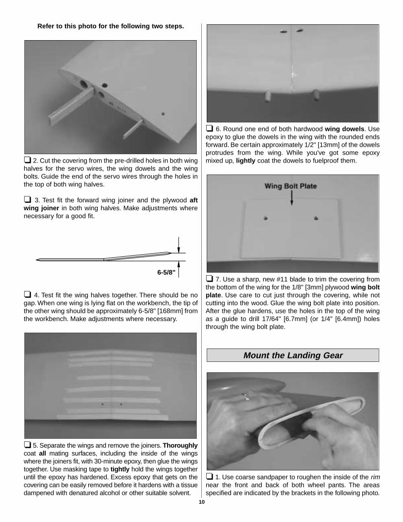
❏ 2. Cut the covering from the pre-drilled holes in both winghalves for the servo wires, the wing dowels and the wingbolts. Guide the end of the servo wires through the holes inthe top of both wing halves.
❏ 3. Test fit the forward wing joiner and the plywood aftwing joiner in both wing halves. Make adjustments wherenecessary for a good fit.
❏ 4. Test fit the wing halves together. There should be nogap. When one wing is lying flat on the workbench, the tip ofthe other wing should be approximately 6-5/8" [168mm] fromthe workbench. Make adjustments where necessary.
❏ 5. Separate the wings and remove the joiners. Thoroughlycoat all mating surfaces, including the inside of the wingswhere the joiners fit, with 30-minute epoxy, then glue the wingstogether. Use masking tape to tightly hold the wings togetheruntil the epoxy has hardened. Excess epoxy that gets on thecovering can be easily removed before it hardens with a tissuedampened with denatured alcohol or other suitable solvent.
❏ 6. Round one end of both hardwood wing dowels. Useepoxy to glue the dowels in the wing with the rounded endsforward. Be certain approximately 1/2" [13mm] of the dowelsprotrudes from the wing. While you've got some epoxymixed up, lightly coat the dowels to fuelproof them.
❏ 7. Use a sharp, new #11 blade to trim the covering fromthe bottom of the wing for the 1/8" [3mm] plywood wing boltplate. Use care to cut just through the covering, while notcutting into the wood. Glue the wing bolt plate into position.After the glue hardens, use the holes in the top of the wingas a guide to drill 17/64" [6.7mm] (or 1/4" [6.4mm]) holesthrough the wing bolt plate.
❏ 1. Use coarse sandpaper to roughen the inside of the rimnear the front and back of both wheel pants. The areasspecified are indicated by the brackets in the following photo.
Mount the Landing Gear
6-5/8"
10

❏ 2. Apply a fillet of epoxy mixed with milled fiberglassinside the pants where shown between the brackets in thephoto. If milled fiberglass is not available, microballoons is asuitable substitute.
Start with the right gear first so the photos will match your progress the first time through.
❏ ❏ 3. Mount an axle onto the right landing gear wire withtwo 3 x 6mm SHCS (socket-head cap screws). The axleshould be positioned so that it is parallel with the bottomhorizontal wires. Tighten and loosen the screws a few timesto mark the wire.
❏ ❏ 4. Remove the axle from the landing gear. File flatspots on the gear where the screws made their marks.
❏ ❏ 5. Reposition the axle on the gear.Tighten the screws.Be certain that the screws have “landed” on the flat spotsand that the axle has remained parallel with the bottomwires. If necessary, remove the axle and adjust the flat spotsuntil you can get the axle positioned correctly. (Taking yourtime here and doing the job correctly will eliminate havingthe axles loosen at the flying field.)
❏ ❏ 6. Cut the covering from the grooves in the landinggear rails in the bottom of the right wing panel. Trim the railand the wing sheeting (where indicated by the arrow) toaccommodate the aft strut where it “angles up” toward themain strut. Also trim the edge of the hole in the forward railto accommodate the bend in the main strut.
❏ ❏ 7. Fit the landing gear into the wing. Drill 1/16"[1.6mm] holes for the screws for four landing gear strapswhere shown, then mount the gear to the wing with thestraps and #2 x 1/2" [13mm] screws. Note: Make certain thestraps are no closer than 1" [25mm] to the forward strut.
❏ ❏ 8. Fit the right wheel pant over the gear. (The rightwheel pant is the one that fits the right wing best when fitover the landing gear.) Slip a wheel collar followed by awheel and another wheel collar onto the axle (if necessary,temporarily remove the axle to install the wheel).
❏ ❏ 9. Center the wheel pant and the wheel laterally on thegear. Also position the pant, fore and aft, where it best fits thewing. Note: If the landing gear wire protrudes below the bottomsurface of the wing and interferes with the fit of the wheel pant,trim the wheel pant as necessary to accommodate the wire.
Flat Spot
11
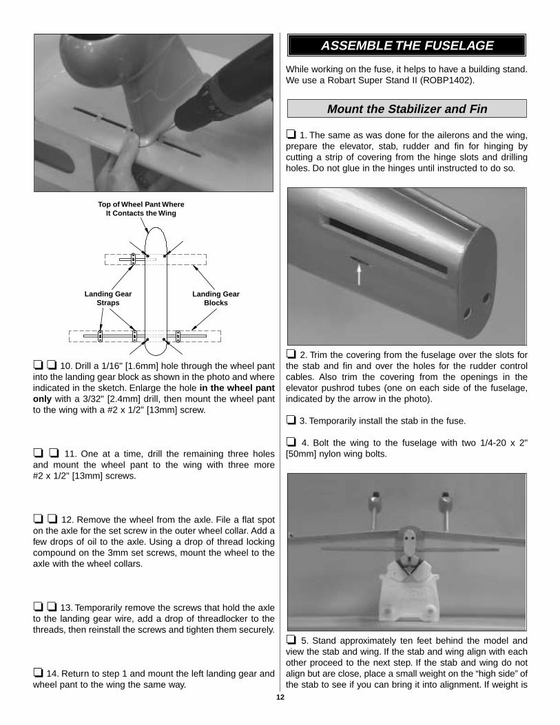
❏ ❏ 10. Drill a 1/16" [1.6mm] hole through the wheel pantinto the landing gear block as shown in the photo and whereindicated in the sketch. Enlarge the hole in the wheel pantonly with a 3/32" [2.4mm] drill, then mount the wheel pantto the wing with a #2 x 1/2" [13mm] screw.
❏ ❏ 11. One at a time, drill the remaining three holes and mount the wheel pant to the wing with three more #2 x 1/2" [13mm] screws.
❏ ❏ 12. Remove the wheel from the axle. File a flat spoton the axle for the set screw in the outer wheel collar. Add afew drops of oil to the axle. Using a drop of thread lockingcompound on the 3mm set screws, mount the wheel to theaxle with the wheel collars.
❏ ❏ 13. Temporarily remove the screws that hold the axleto the landing gear wire, add a drop of threadlocker to thethreads, then reinstall the screws and tighten them securely.
❏ 14. Return to step 1 and mount the left landing gear andwheel pant to the wing the same way.
While working on the fuse, it helps to have a building stand.We use a Robart Super Stand II (ROBP1402).
❏ 1. The same as was done for the ailerons and the wing,prepare the elevator, stab, rudder and fin for hinging bycutting a strip of covering from the hinge slots and drillingholes. Do not glue in the hinges until instructed to do so.
❏ 2. Trim the covering from the fuselage over the slots forthe stab and fin and over the holes for the rudder controlcables. Also trim the covering from the openings in theelevator pushrod tubes (one on each side of the fuselage,indicated by the arrow in the photo).
❏ 3. Temporarily install the stab in the fuse.
❏ 4. Bolt the wing to the fuselage with two 1/4-20 x 2"[50mm] nylon wing bolts.
❏ 5. Stand approximately ten feet behind the model andview the stab and wing. If the stab and wing align with eachother proceed to the next step. If the stab and wing do notalign but are close, place a small weight on the “high side” ofthe stab to see if you can bring it into alignment. If weight is
Mount the Stabilizer and Fin
ASSEMBLE THE FUSELAGE
Top of Wheel Pant WhereIt Contacts the Wing
Landing GearStraps
Landing GearBlocks
12
not enough, remove the stab from the fuselage. Lightly sandthe slots in the fuselage as necessary to get the stab to alignwith the wing. Reinsert the stab and check the alignment.
❏ 6. Remove the wing from the fuse. Center the trailing edgeof the stab in the fuse by taking accurate measurements fromboth tips to the sides of the fuse.
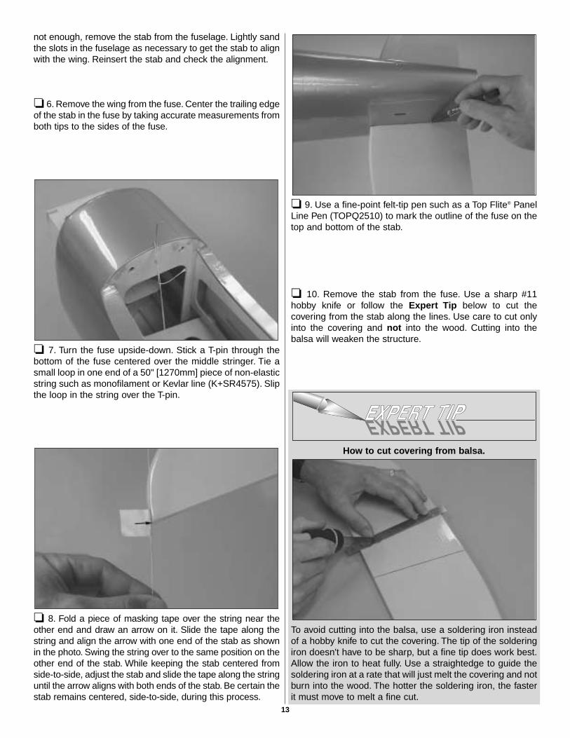
❏ 7. Turn the fuse upside-down. Stick a T-pin through thebottom of the fuse centered over the middle stringer. Tie asmall loop in one end of a 50" [1270mm] piece of non-elasticstring such as monofilament or Kevlar line (K+SR4575). Slipthe loop in the string over the T-pin.
❏ 8. Fold a piece of masking tape over the string near theother end and draw an arrow on it. Slide the tape along thestring and align the arrow with one end of the stab as shownin the photo. Swing the string over to the same position on theother end of the stab. While keeping the stab centered fromside-to-side, adjust the stab and slide the tape along the stringuntil the arrow aligns with both ends of the stab. Be certain thestab remains centered, side-to-side, during this process.
❏ 9. Use a fine-point felt-tip pen such as a Top Flite® PanelLine Pen (TOPQ2510) to mark the outline of the fuse on thetop and bottom of the stab.
❏ 10. Remove the stab from the fuse. Use a sharp #11hobby knife or follow the Expert Tip below to cut thecovering from the stab along the lines. Use care to cut onlyinto the covering and not into the wood. Cutting into thebalsa will weaken the structure.
How to cut covering from balsa.
To avoid cutting into the balsa, use a soldering iron insteadof a hobby knife to cut the covering. The tip of the solderingiron doesn't have to be sharp, but a fine tip does work best.Allow the iron to heat fully. Use a straightedge to guide thesoldering iron at a rate that will just melt the covering and notburn into the wood. The hotter the soldering iron, the fasterit must move to melt a fine cut.
13
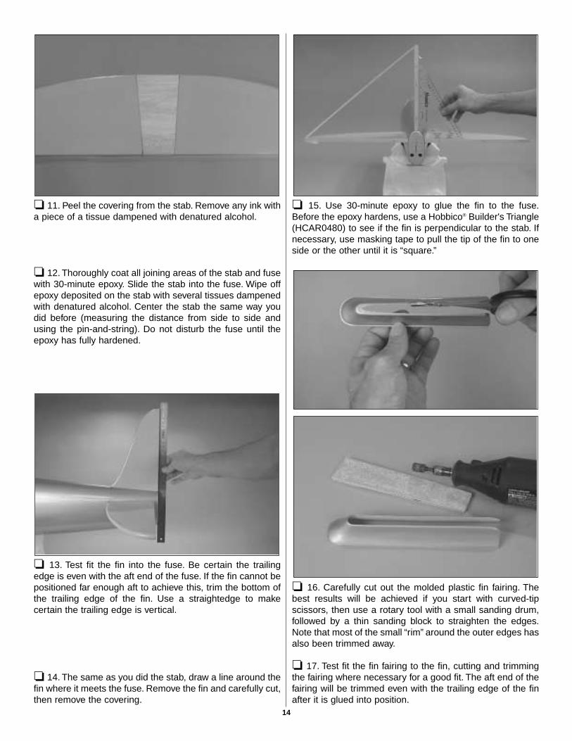
❏ 11. Peel the covering from the stab. Remove any ink witha piece of a tissue dampened with denatured alcohol.
❏ 12. Thoroughly coat all joining areas of the stab and fusewith 30-minute epoxy. Slide the stab into the fuse. Wipe offepoxy deposited on the stab with several tissues dampenedwith denatured alcohol. Center the stab the same way youdid before (measuring the distance from side to side andusing the pin-and-string). Do not disturb the fuse until theepoxy has fully hardened.
❏ 13. Test fit the fin into the fuse. Be certain the trailingedge is even with the aft end of the fuse. If the fin cannot bepositioned far enough aft to achieve this, trim the bottom ofthe trailing edge of the fin. Use a straightedge to makecertain the trailing edge is vertical.
❏ 14. The same as you did the stab, draw a line around thefin where it meets the fuse. Remove the fin and carefully cut,then remove the covering.
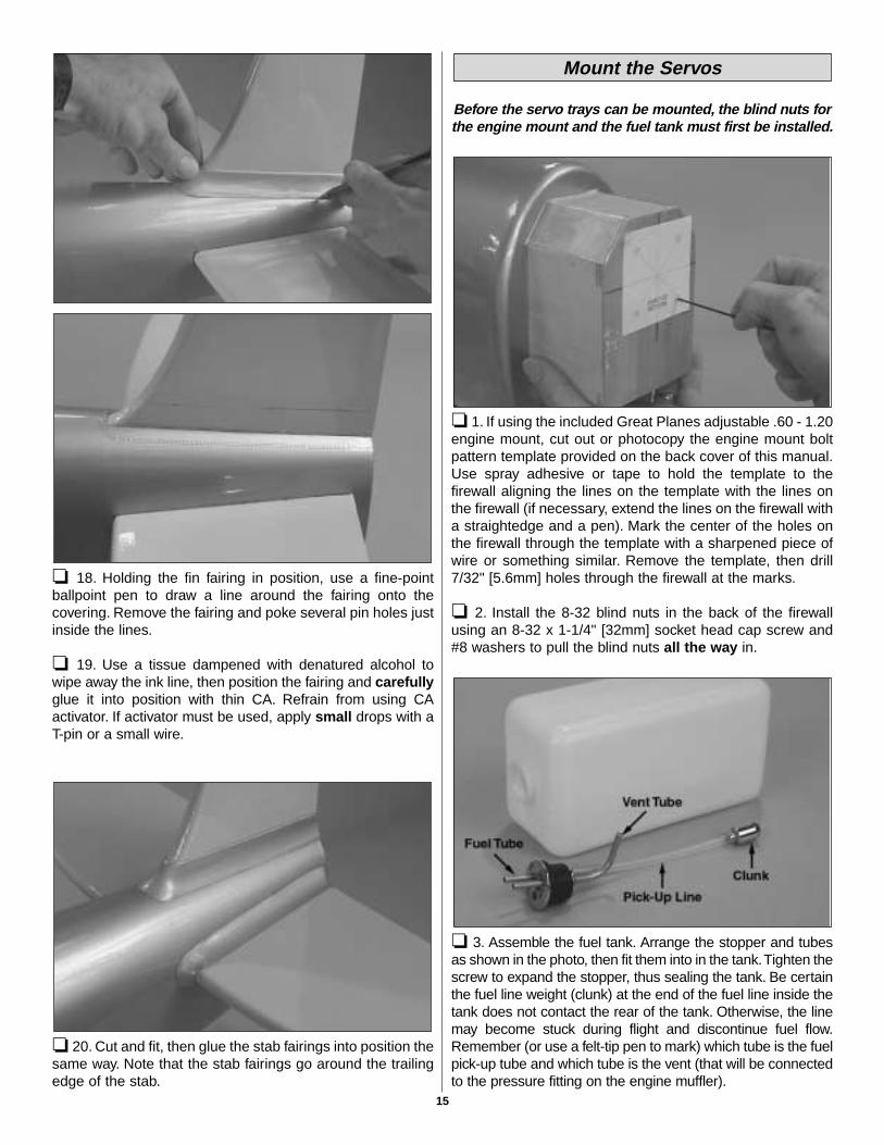
❏ 15. Use 30-minute epoxy to glue the fin to the fuse.Before the epoxy hardens, use a Hobbico® Builder's Triangle(HCAR0480) to see if the fin is perpendicular to the stab. Ifnecessary, use masking tape to pull the tip of the fin to oneside or the other until it is “square.”
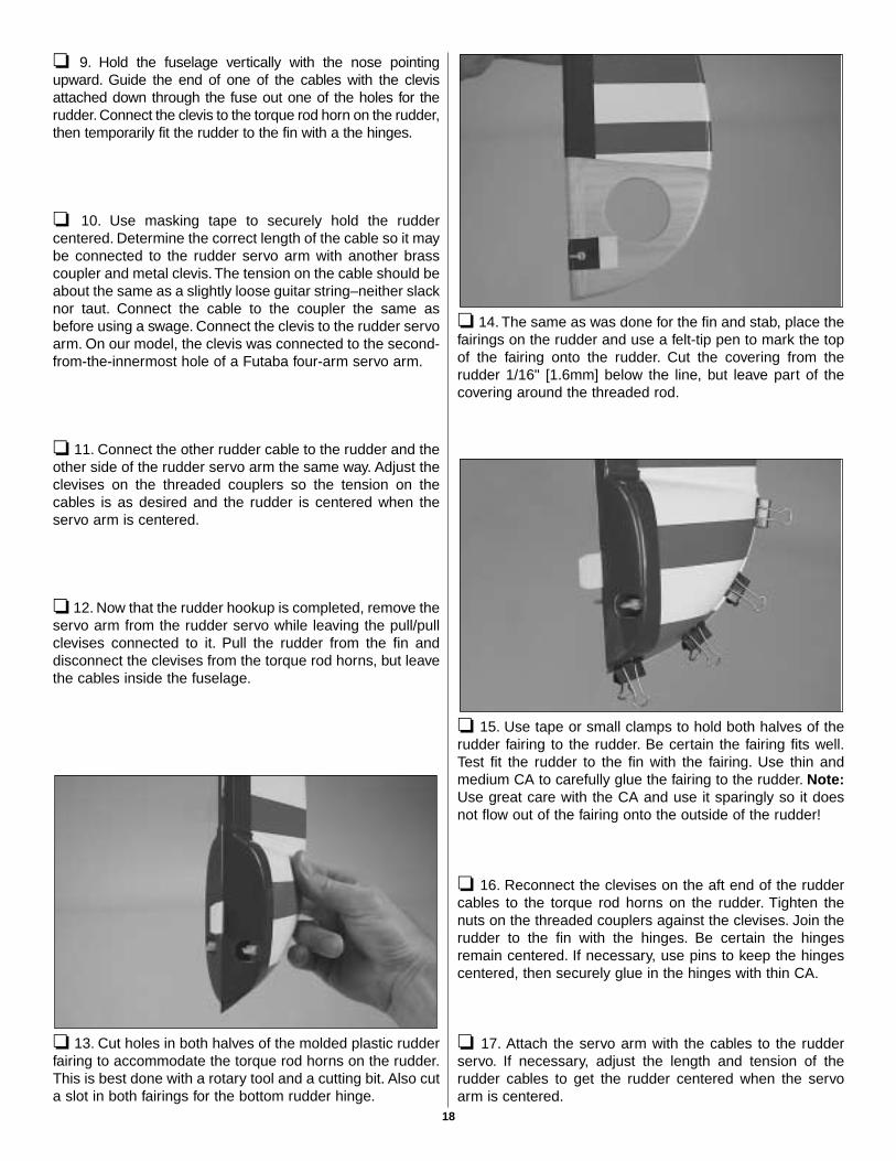
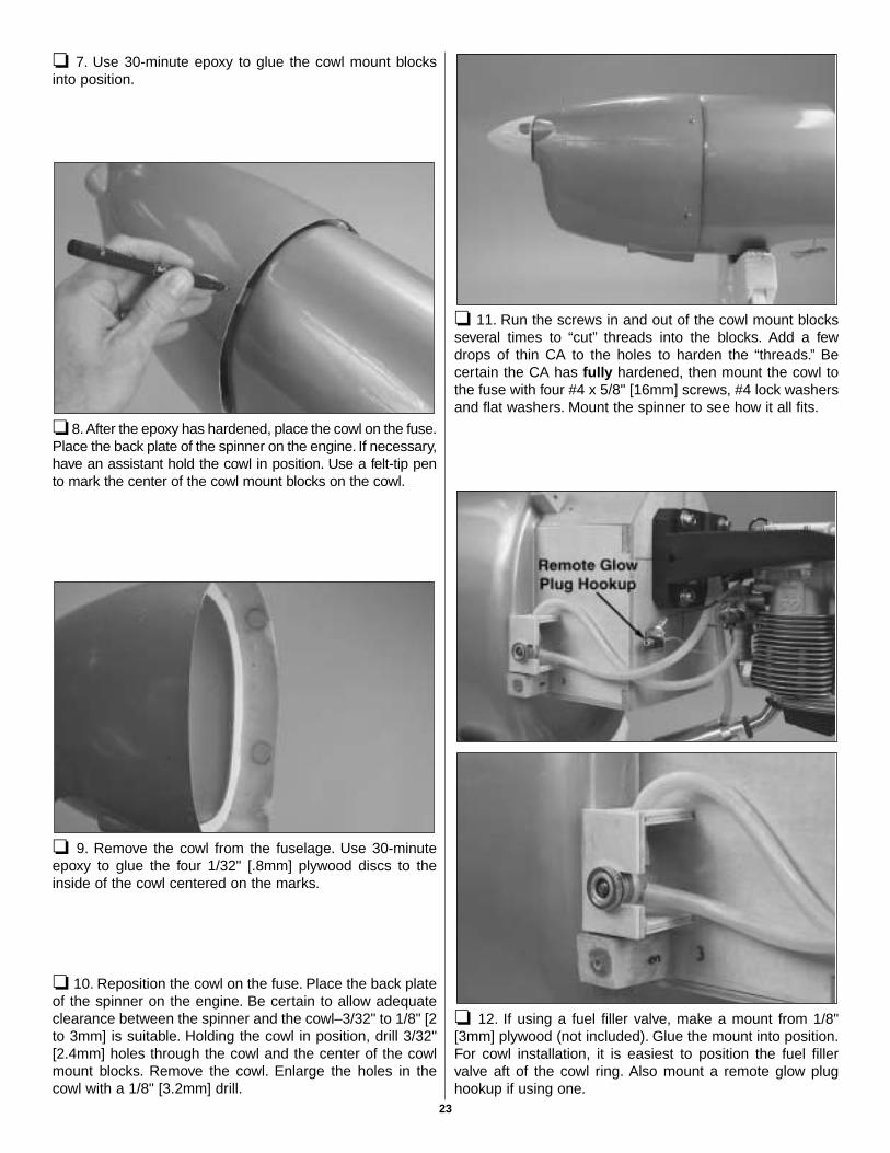
❏ 16. Carefully cut out the molded plastic fin fairing. Thebest results will be achieved if you start with curved-tipscissors, then use a rotary tool with a small sanding drum,followed by a thin sanding block to straighten the edges.Note that most of the small “rim” around the outer edges hasalso been trimmed away.
❏ 17. Test fit the fin fairing to the fin, cutting and trimmingthe fairing where necessary for a good fit. The aft end of thefairing will be trimmed even with the trailing edge of the finafter it is glued into position.
14
❏ 18. Holding the fin fairing in position, use a fine-pointballpoint pen to draw a line around the fairing onto thecovering. Remove the fairing and poke several pin holes justinside the lines.
❏ 19. Use a tissue dampened with denatured alcohol towipe away the ink line, then position the fairing and carefullyglue it into position with thin CA. Refrain from using CAactivator. If activator must be used, apply small drops with aT-pin or a small wire.
❏ 20. Cut and fit, then glue the stab fairings into position thesame way. Note that the stab fairings go around the trailingedge of the stab.
Before the servo trays can be mounted, the blind nuts forthe engine mount and the fuel tank must first be installed.
❏ 1. If using the included Great Planes adjustable .60 - 1.20engine mount, cut out or photocopy the engine mount boltpattern template provided on the back cover of this manual.Use spray adhesive or tape to hold the template to thefirewall aligning the lines on the template with the lines onthe firewall (if necessary, extend the lines on the firewall witha straightedge and a pen). Mark the center of the holes onthe firewall through the template with a sharpened piece ofwire or something similar. Remove the template, then drill7/32" [5.6mm] holes through the firewall at the marks.
❏ 2. Install the 8-32 blind nuts in the back of the firewallusing an 8-32 x 1-1/4" [32mm] socket head cap screw and#8 washers to pull the blind nuts all the way in.
❏ 3. Assemble the fuel tank. Arrange the stopper and tubesas shown in the photo, then fit them into in the tank.Tighten thescrew to expand the stopper, thus sealing the tank. Be certainthe fuel line weight (clunk) at the end of the fuel line inside thetank does not contact the rear of the tank. Otherwise, the linemay become stuck during flight and discontinue fuel flow.Remember (or use a felt-tip pen to mark) which tube is the fuelpick-up tube and which tube is the vent (that will be connectedto the pressure fitting on the engine muffler).
Mount the Servos
15

❏ 4. Install the fuel tank so the neck fits through the hole inthe firewall. Be certain that you have installed the tank so thevent tube inside the tank is pointing upward. Use a couple of#64 rubber bands (not included) to hold the tank to the tankfloor. Note: There may be a little resistance installing the tankat the point when it is at an angle pointing toward the top of thefuselage, but with a little “persuasion” it will slide into position.
❏ 5.Test fit the rudder servo and both elevator servos in the1/8" [3mm] plywood aft servo tray. If necessary, enlarge theopening to accommodate the servos. Drill 1/16" holes in thetray for mounting the servos, then add a few drops of thin CAto the holes and allow to harden. Don't mount the servos intothe tray until instructed to do so.
Refer to this photo for the following four steps.
❏ 6. Use epoxy to securely glue the aft servo tray to the topedges of the crutches inside the fuselage. For additionalstrength, add milled fiberglass (GPMR6165) to the epoxy.Use clamps to hold the aft servo tray in position until theepoxy hardens.
❏ 7. Determine which way you will be mounting the 1/8"[3mm] plywood forward servo tray. Position the tray toprovide the best alignment of the throttle servo with thecarburetor arm on the engine. As can be seen in the photo atstep 6 on page 21 the forward servo tray in this model wasmounted with the throttle servo nearest the rear of thefuselage on the left side.
❏ 8. Securely glue both 1/4" x 3/8" x 6-1/4" [6 x 10 x 160mm]hardwood forward servo tray rails to the plywood inner fusesides. The bottom edge of the rails must be even with the topedge of the opening in the 1/16" ply inner fuse sides.
❏ 9. Trim both sides of the forward servo tray to get it to fitbetween the inner fuse sides on the rails. Drill three evenlyspaced 1/16" [1.6mm] holes through both sides of the trayand the rails (see step 6 on page 21). Add a few drops of thinCA to each hole and allow to fully harden.
❏ 10. Remove the servo tray. Enlarge the holes in the traywith a 3/32" [2.4mm] drill. Mount the tray to the rails with six#2 x 1/2" [13mm] screws and #2 washers.
❏ 11. Mount the throttle servo, receiver and battery pack tothe tray. Use hard balsa sticks (not included) and rubberbands to secure the receiver and battery pack. Place 1/4"[6mm] or 1/2" [13mm] R/C foam rubber under the receiverand battery.
❏ 12. Mount the forward servo tray in the fuselage andmount the rudder and elevator servos to the aft servo tray. Ifnecessary, cut the front of the elevator pushrod tubes(factory installed in the fuselage) a few inches short of theelevator servos.
16

❏ 1. Cut the covering from the hole in both sides of the rudderfor the 6-32 x 1-1/2" [38mm] threaded control rod. Temporarilythread the rod into the rudder until it is centered. (A hemostatwas used to thread the control rod into the rudder.)
❏ 2. Use a #36 (or 7/64" [2.8mm]) drill to enlarge the hole inboth nylon torque rod horns. Use a 6-32 tap to make threadsin the horns. Screw the horns onto the threaded rod on therudder until the top of the horns are even with the ends of therod. (The horns can be seen in photos on page 18.)
❏ 3. Test fit the rudder to the fin with the hinges. Ifnecessary, enlarge the holes in the back of the fuselage sothe torque rod horns will not contact the edges when therudder is moved back and forth.
❏ 4. Slip a small copper tube (also called a “swage”)and athreaded brass coupler with a clevis about 6" [150mm] ontoone end of the braided steel rudder pull/pull cable.
❏ 5. Insert the end of the cable back down through theswage, then loop it around and thread it back up through theswage (as indicated by the dashed line in the photo).
❏ 6. Pull the short end of the cable tight through the swageuntil the loop “ends” at the swage.
❏ 7. Pull the long end of the cable through the swage,decreasing the loop around the threaded brass coupler until itis approximately 3/8" [9mm] long. Use pliers to tightly squishthe swage, then cut the excess cable at the end of the swage.
❏ 8. Connect another threaded brass coupler to the otherend of the cable the same way, then cut the cable into twoequal lengths.
Hook Up the Rudder
17
❏ 9. Hold the fuselage vertically with the nose pointingupward. Guide the end of one of the cables with the clevisattached down through the fuse out one of the holes for therudder. Connect the clevis to the torque rod horn on the rudder,then temporarily fit the rudder to the fin with a the hinges.
❏ 10. Use masking tape to securely hold the ruddercentered. Determine the correct length of the cable so it maybe connected to the rudder servo arm with another brasscoupler and metal clevis. The tension on the cable should beabout the same as a slightly loose guitar string–neither slacknor taut. Connect the cable to the coupler the same asbefore using a swage. Connect the clevis to the rudder servoarm. On our model, the clevis was connected to the second-from-the-innermost hole of a Futaba four-arm servo arm.
❏ 11. Connect the other rudder cable to the rudder and theother side of the rudder servo arm the same way. Adjust theclevises on the threaded couplers so the tension on thecables is as desired and the rudder is centered when theservo arm is centered.
❏ 12. Now that the rudder hookup is completed, remove theservo arm from the rudder servo while leaving the pull/pullclevises connected to it. Pull the rudder from the fin anddisconnect the clevises from the torque rod horns, but leavethe cables inside the fuselage.
❏ 13. Cut holes in both halves of the molded plastic rudderfairing to accommodate the torque rod horns on the rudder.This is best done with a rotary tool and a cutting bit. Also cuta slot in both fairings for the bottom rudder hinge.
❏ 14. The same as was done for the fin and stab, place thefairings on the rudder and use a felt-tip pen to mark the topof the fairing onto the rudder. Cut the covering from therudder 1/16" [1.6mm] below the line, but leave part of thecovering around the threaded rod.
❏ 15. Use tape or small clamps to hold both halves of therudder fairing to the rudder. Be certain the fairing fits well.Test fit the rudder to the fin with the fairing. Use thin andmedium CA to carefully glue the fairing to the rudder. Note:Use great care with the CA and use it sparingly so it doesnot flow out of the fairing onto the outside of the rudder!
❏ 16. Reconnect the clevises on the aft end of the ruddercables to the torque rod horns on the rudder. Tighten thenuts on the threaded couplers against the clevises. Join therudder to the fin with the hinges. Be certain the hingesremain centered. If necessary, use pins to keep the hingescentered, then securely glue in the hinges with thin CA.
❏ 17. Attach the servo arm with the cables to the rudderservo. If necessary, adjust the length and tension of therudder cables to get the rudder centered when the servoarm is centered.
18

❏ 1. Permanently join both elevators to the stab by gluingin the hinges with thin CA.
❏ 2. Make an elevator pushrod by threading a 4-40 nut anda 4-40 clevis with a silicone retainer onto a 4-40 x 36"[910mm] pushrod. Connect the clevis to the outer hole of alarge nylon control horn. Prepare another pushrod the sameway. Insert the pushrods into the guide tubes from the rearof the fuselage.
❏ 3. Position the pushrods so the holes in the control hornsare over the hinge gap between the elevators and stab.
❏ 4. Use a felt-tip pen to mark the front of the pushrodswhere they are to be cut for connecting to the elevator servoarms with metal solder-on clevises.
❏ 5. Remove the pushrods from the fuselage, cut them tothe correct length, then read the following Expert Tip andsolder the clevises to the ends of both pushrods.
How to Solder
A. Use denatured alcohol or other solvent to removeresidual oil from the pushrod.
B. Use coarse sandpaper to thoroughly roughen the endof the pushrod where it is to be soldered.
C. Apply a few drops of soldering flux to the end of thepushrod, then use a soldering iron or a torch to heat it.Coat the end of the pushrod with silver solder(GPMR8070) by touching the solder to it. The heat ofthe pushrod should melt the solder–not the flame of thetorch or soldering iron–thus allowing the solder to flow.Note: Do not use silver solder for electrical soldering.
D. Join the clevis to the pushrod. Add another drop of flux,then heat and add solder. The same as before, the heatof the parts being soldered should melt the solder, thusallowing it to flow. Allow the joint to cool withoutdisturbing. Avoid excess blobs, but make certain thejoint is thoroughly soldered. The solder should be shiny,not rough. If necessary, heat the joint again and allow tocool slowly without disturbing.
E. After the joint has solidified but while it is still hot, carefullyuse a cloth to wipe away soldering flux. Important: Afterthe joint cools, coat with oil to protect it from rusting.
❏ 6. Remove the threaded clevises from the aft end of thepushrods. Guide the pushrods through the front of thepushrod tubes from inside the fuselage and thread theclevises back onto the pushrods. Connect the front of thepushrods to the elevator servo arms. Make slight bends inthe aft end of the pushrods as necessary, then drill 3/32"[2.4mm] holes through the elevators and mount the hornswith 2-56 x 3/4" [19mm] screws and the nylon plate thatcame with the control horns.
Correct Incorrect
Hook Up the Elevators
19

Refer to this photo while mounting the tail gear.
❏ 1. Drill a 1/8" [3.2mm] hole through the middle of thebottom of the fuse for the tail gear wire 5-7/8" [150mm] fromthe aft end. Optional: Use a 5/32" brass tube sharpened atone end to drill the hole. Cut 1" [25mm] from the end of thebrass tube and glue it into the hole. This will provide abearing for the tail gear wire.
❏ 2. Insert the tail gear wire into the hole (or brass tube).Place two nylon hump-straps on the wire where shown inthe photo. Accurately mark the center of the holes in thestraps onto the bottom of the fuse.
❏ 3. Drill 5/32" [4mm] holes (or use the 5/32" brass tube tomake the holes) all the way through the bottom of the fuseat the marks.
❏ 4. Cut four 1" [25mm] pieces from the 36" [910mm] plastictube (the one with the ridges). Use thick CA or epoxy to gluea tube in each of the four holes. Note: If using thick CA, workquickly. If necessary, use a small mallet or a wood block totap the tubes down into the holes before the CA takes hold.
❏ 5. Mount the tail gear to the fuse with the straps and four#2 x 1/2" [13mm] screws.
❏ 6. Use a 3/16" [4.8mm] brass tube sharpened on one end tocut a hole through the bottom of the fuse in alignment with thearm on the right side of the tail gear.The angle of the hole doesnot have to be precise because when installed, the pushrod willbe bent as necessary to align with the steering arm.
❏ 7. Roughen one end of the 3/16" x 36" [4.8 x 910mm]pushrod tube. Guide the tube through the fuse, so theroughened end is in the hole, then cut the front of the tubeapproximately 2" [50mm] short of the rudder servo arm. Gluethe tube in the hole and trim it even with the bottom of the fuse.
❏ 8. Mount the 0-80 threaded ball to the outer hole of thetail wheel steering arm with an 0-80 nut and a small drop ofthreadlocker. Make the tail wheel pushrod from a 2-56 x 36"[910mm] pushrod with a nylon ball link on the aft end. Install
RETAINER
Mount the Tailgear
20

the pushrod into the pushrod tube, then bend it asnecessary to connect to the steering arm. Mount a screw-lock connector to the rudder servo arm with a nylon retainer.Temporarily fit the pushrod into the connector.
❏ 9. Make a brace for the front of the tail wheel pushrodtube from the 1/4" x 1/2" x 6" [6 x 13 x 150mm] balsa stick.Drill a 3/16" [4.8mm] hole through the brace, then slip thebrace over the tail steering pushrod tube. Glue the brace inthe fuse so the pushrod aligns with the screw-lock connectoron the rudder servo. Glue the pushrod tube to the brace.Center the tail wheel, then secure the pushrod to the screw-lock connector with a 4-40 x 1/8" [3.2mm] screw.
❏ 1. Mount the engine mount to the firewall with four 8-32x 1" [25mm] SHCS, #8 lock washers and #8 flat washers,but do not tighten the screws. Adjust the mount to fit yourengine and tighten the screws.
❏ 2. Mount the back plate of the spinner to the engine.Position the engine on the mount so the back plate will be 5-7/8" [150mm] from the firewall. Temporarily hold the engineto the mount with a small “C”-clamp. Use a Great PlanesDead Center™ Hole Locator (GPMR8130-shown in thephoto) or another method to mark the locations of the holesfor mounting the engine.
❏ 3. Remove the engine mount from the firewall. Drill #29(or 9/64" [3.6mm]) holes through the mount at the marks.Tap 8-32 threads into the holes. Mount the engine mount tothe fuse, then mount the engine to the mount with 8-32 x 1"[25mm] screws and #8 lock washers. Center the mount onthe vertical line on the firewall, then tighten the bolts thathold the mount.
❏ 4. Drill a 3/16" [4.8mm] hole through the firewall for thethrottle pushrod in alignment with the carburetor arm.
❏ 5. Cut the 3/16" x 12" [4.8 x 300mm] pushrod tube to thecorrect length, then roughen one end and guide it throughthe hole you drilled. Thread a nylon clevis twenty full turnsonto the 2-56 x 18" [460mm] pushrod. Bend the front of thepushrod as necessary, then connect the clevis on thepushrod to the carb arm.
❏ 6. Cut the other end of the pushrod to the correct length,then bend it as necessary to connect to a screw lockconnector on the throttle servo arm. Similar to the braceused for the tail wheel steering pushrod tube, make a bracefor the throttle pushrod tube from the piece of leftover 1/4" x 1/2" [6 x 13mm] balsa stick and glue it into position.
Mount the Engine
21

❏ 1. Use 30-minute epoxy mixed with lightweight Top FliteMicroballoons Filler to glue the 1/8" [3mm] plywood cowlring inside the cowl an equal distance from the aft edge allthe way around. The distance should be approximately 1"[25mm] to 1-3/8" [35mm]–wherever it fits best. Set the cowlaside and allow the epoxy to harden.
❏ 2. Cut the holes in the front of the cowl for the engine crankshaft and for the air inlets where shown. (Though not markedon the cowl, for scale effect, an additional round hole was cutto match the hole on the full-size STA-M.) A Dremel with acarbide cutter, followed by a drum sander, works best forcutting the holes. Use protective goggles and a particle maskwhen cutting fiberglass. Finish by sanding the openings byhand with 400-grit sandpaper to smooth the edges.
❏ 3. Determine your engine exhaust configuration. With theO.S.® MAX .91 Surpass™ II used on this model, an O.S. “in”type exhaust header pipe (OSMG2624) was used toposition the muffler near the bottom of the cowl. (Thisrequires removing a portion of the bottom of the plywoodcowl ring to accommodate the muffler.)
❏ 4. Make two upper cowl mount blocks and two lowercowl mount blocks to fit the full-size drawings above from the9/16" x 9/16" x 1-3/16" [14.3 x 14.3 x 30mm] hardwood blocks.
❏ 5. Use coarse sandpaper to roughen the fuelproofcoating where the cowl mount blocks will be glued (indicatedby the arrows) so the epoxy will adhere.Temporarily hold thecowl mount blocks in position with a rubber band.
❏ 6. Test fit the cowl. The cowl should not fit tightly over theblocks.There should be approximately 1/32" [.8mm] betweenthe cowl and the mounting blocks. If necessary, trim the cowlmount blocks to get the cowl to fit correctly.
LowerCowl
Mount
UpperCowl
Mount
Mount the Cowl
22
❏ 7. Use 30-minute epoxy to glue the cowl mount blocksinto position.
❏ 8. After the epoxy has hardened, place the cowl on the fuse.Place the back plate of the spinner on the engine. If necessary,have an assistant hold the cowl in position. Use a felt-tip pento mark the center of the cowl mount blocks on the cowl.
❏ 9. Remove the cowl from the fuselage. Use 30-minuteepoxy to glue the four 1/32" [.8mm] plywood discs to theinside of the cowl centered on the marks.
❏ 10. Reposition the cowl on the fuse. Place the back plateof the spinner on the engine. Be certain to allow adequateclearance between the spinner and the cowl–3/32" to 1/8" [2to 3mm] is suitable. Holding the cowl in position, drill 3/32"[2.4mm] holes through the cowl and the center of the cowlmount blocks. Remove the cowl. Enlarge the holes in thecowl with a 1/8" [3.2mm] drill.
❏ 11. Run the screws in and out of the cowl mount blocksseveral times to “cut” threads into the blocks. Add a fewdrops of thin CA to the holes to harden the “threads.” Becertain the CA has fully hardened, then mount the cowl tothe fuse with four #4 x 5/8" [16mm] screws, #4 lock washersand flat washers. Mount the spinner to see how it all fits.
❏ 12. If using a fuel filler valve, make a mount from 1/8"[3mm] plywood (not included). Glue the mount into position.For cowl installation, it is easiest to position the fuel fillervalve aft of the cowl ring. Also mount a remote glow plughookup if using one.
23

❏ 13. Cut holes in the cowl where required for the fuel fillervalve, the remote glow plug hookup and the needle valve.
❏ 14. Use epoxy or fuelproof paint to coat any bare woodsuch as the cowl ring, the cowl mounting blocks and themount for the fuel filler valve.
❏ 15. If you feel it necessary for the engine you are using,cut additional holes in the cowl for cooling. With the O.S.®
MAX .91 FS no additional holes were required.
❏ 1. Mount the on/off switch in a convenient location on theside of the fuselage opposite the engine exhaust. The switchon the model shown was mounted with a Great PlanesSwitch and Charge Jack (GPMM1000). This setup providesaccess to the battery charging cord from outside the modelfor quick field charging and battery monitoring. If you havenot yet already done so, mount the battery and receiver. Thefinal location of the battery pack could be determined whilebalancing the model (to minimize or eliminate therequirement for additional ballast), but the model shown inthis manual required no tail weight with the componentsmounted where shown. Be certain the receiver and batteryare cushioned with 1/4" or 1/2" [6mm or 13mm] R/C foamrubber to protect them from vibration. Connect all the wiresto the receiver and hook up the battery and switch.
❏ 2. Glue the piece of leftover throttle pushrod tube insidethe fuselage to keep the receiver antenna away from theservos and pushrods. Make a strain relief from a cut-offservo arm and slip it onto the antenna, then route theantenna through the tube and out of the fuselage. On themodel shown in the manual the antenna was routed out thebottom of the fuselage through a small piece of tubing, thenconnected to a hook fashioned from another leftover servoarm which was connected to a rubber band and a wire hookinserted into the bottom of the fuse.
❏ 3. Make certain all the servo arms are secured to theservos with the screws that came with them and that all theclevises have retainers on them.
Finish the Radio Installation
24
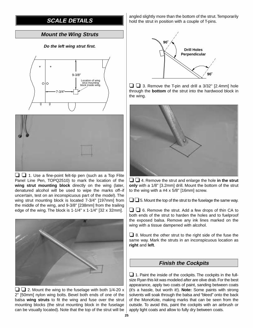
Do the left wing strut first.
❏ ❏ 1. Use a fine-point felt-tip pen (such as a Top FlitePanel Line Pen, TOPQ2510) to mark the location of thewing strut mounting block directly on the wing (later,denatured alcohol will be used to wipe the marks off–ifuncertain, test on an inconspicuous part of the model). Thewing strut mounting block is located 7-3/4" [197mm] fromthe middle of the wing, and 9-3/8" [238mm] from the trailingedge of the wing. The block is 1-1/4" x 1-1/4" [32 x 32mm].
❏ ❏ 2. Mount the wing to the fuselage with both 1/4-20 x2" [50mm] nylon wing bolts. Bevel both ends of one of thebalsa wing struts to fit the wing and fuse over the strutmounting blocks (the strut mounting block in the fuselagecan be visually located). Note that the top of the strut will be
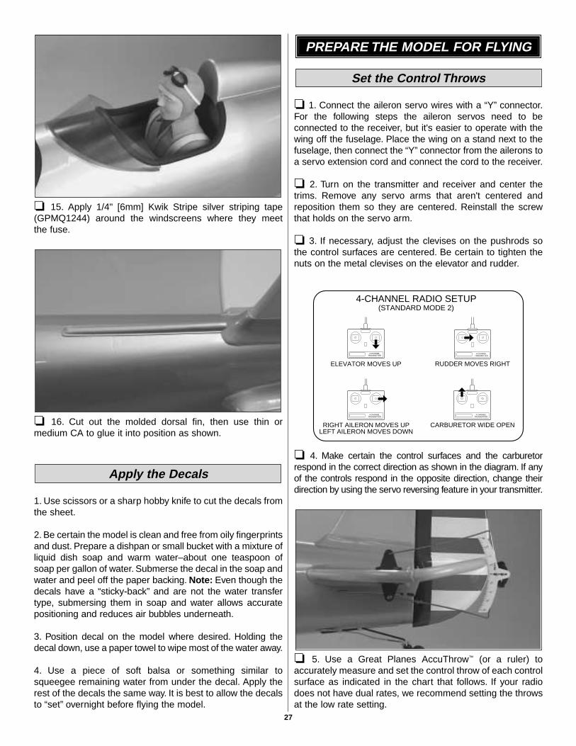
angled slightly more than the bottom of the strut.Temporarilyhold the strut in position with a couple of T-pins.
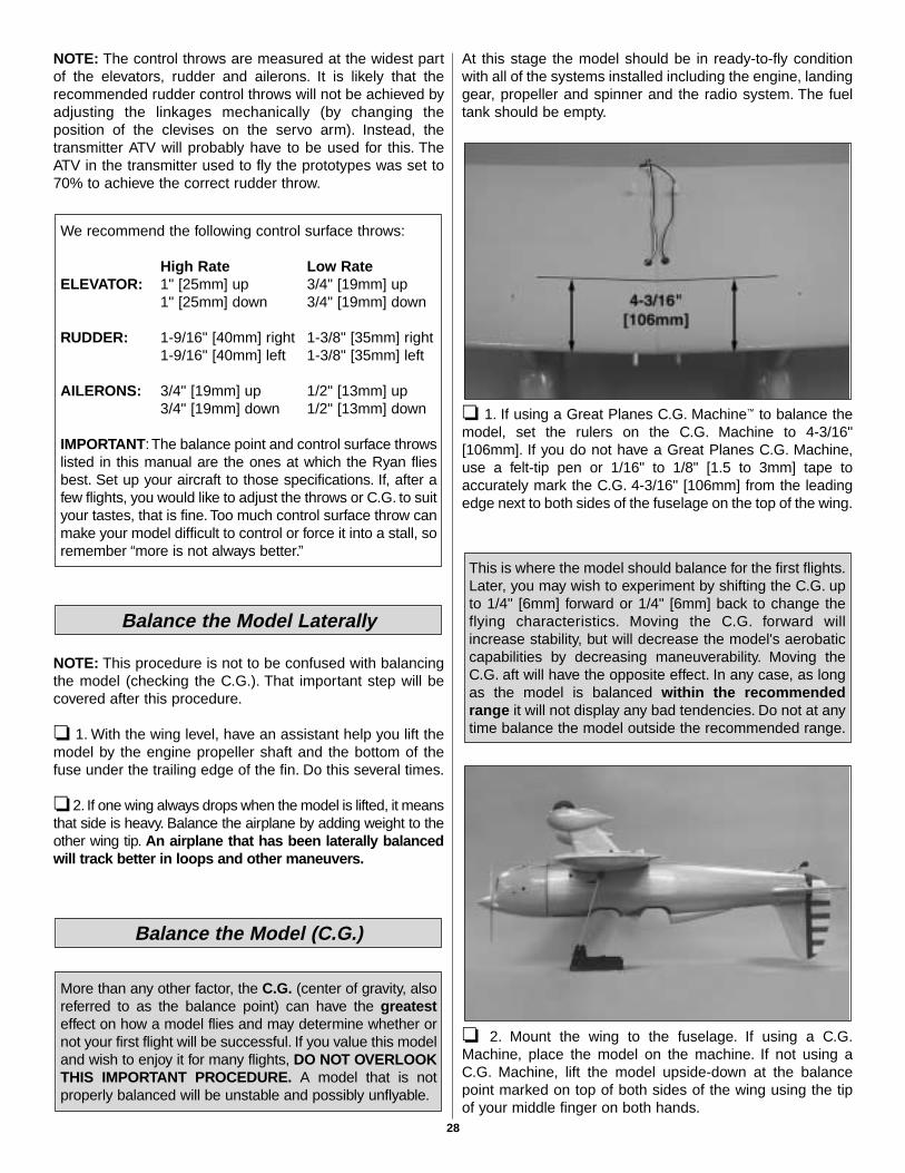
❏ ❏ 3. Remove the T-pin and drill a 3/32" [2.4mm] holethrough the bottom of the strut into the hardwood block inthe wing.
❏ ❏ 4. Remove the strut and enlarge the hole in the strutonly with a 1/8" [3.2mm] drill. Mount the bottom of the strutto the wing with a #4 x 5/8" [16mm] screw.
❏ ❏ 5. Mount the top of the strut to the fuselage the same way.
❏ ❏ 6. Remove the strut. Add a few drops of thin CA toboth ends of the strut to harden the holes and to fuelproofthe exposed balsa. Remove any ink lines marked on thewing with a tissue dampened with alcohol.
❏ 8. Mount the other strut to the right side of the fuse thesame way. Mark the struts in an inconspicuous location asright and left.
❏ 1. Paint the inside of the cockpits. The cockpits in the full-size Ryan this kit was modeled after are olive drab. For the bestappearance, apply two coats of paint, sanding between coats(it's a hassle, but worth it!). Note: Some paints with strongsolvents will soak through the balsa and “bleed” onto the backof the MonoKote, making marks that can be seen from theoutside. To avoid this, paint the cockpits with an airbrush orapply light coats and allow to fully dry between coats.
Finish the Cockpits
Drill HolesPerpendicular
90˚
90˚
7-3/4"
9-3/8"
Location of wingstrut mounting
block inside wing.
Mount the Wing Struts
SCALE DETAILS
25

❏ 2. Cut out the front and rear instrument panel stickersand place them in the model (the front instrument panel willhave to be trimmed to accommodate the wing strut blocks).
❏ 3. Use the windshield pattern in the back of the manualto cut out the windshields from the supplied clear plasticsheets. Start with curved-tip plastic cutting scissors, thentrue the edges with progressively finer grits of sandpaper.
❏ 4. Have an assistant hold one of the windscreens inposition on the fuse. Use a fine-point felt-tip pen to draw aline on the fuse around the edge of the windscreen.
Use this photo for the next three steps.
❏ 5. Use a hobby knife with a new #11 blade to cut throughthe covering along the line you marked. If adding a flat blackanti-glare panel, remove the aluminum covering behind theline. Use the covering as a template to cut another piecefrom flat black MonoKote film (or use fine sandpaper to scuffa piece of regular black MonoKote film). Iron the “anti-glare”panel covering into position, with a 1/16" [2mm] gapbetween the black and the aluminum. If not making an anti-glare panel, make another cut in the covering 1/16" [2mm] infront of the first cut. Remove the strip of covering from thefuse, leaving a 1/16" [2mm] strip of exposed balsa where thewindscreen will be glued.
❏ 6. Use a #11 blade to split both pieces of black rubbertubing for the cockpit coaming. Fit the coaming around thecockpit openings with the ends joining at the rear, but don'tglue them into position yet.
❏ 7. Prepare the other cockpit the same way.
❏ 8. Trim the molded plastic turtledeck to fit the fuse, thentemporarily fit it into position. Trim the rear cockpit coamingto accommodate the turtledeck.
❏ 9. The same way a line was drawn around thewindshields, draw a line around the turtledeck onto thecovering. Remove the turtledeck, then cut the covering 1/16"[2mm] inside the line you marked and peel off the covering.
❏ 10. Wipe away the ink with a tissue dampened withdenatured alcohol. Position the turtledeck, then carefullyglue it into position with thin CA. Avoid using CA activator,but if necessary, activator may be applied in small amountsby spraying the CA on a T-pin, then using the T-pin totransfer small drops where necessary. If rapidly curing CAfogs the covering or forms small white bubbles, it may becleaned up with CA debonder. Use care, because debonderwill also remove the paint from the turtledeck.
❏ 11. Use thin CA sparingly to glue the coaming to the fuse.
❏ 12. Glue the windscreens to the fuse. This was done onour prototype models using thin and medium CA asnecessary, but great care must be used not to smear thewindshields by using too much CA. The same as theturtledeck, CA activator may be applied sparingly with a T-pin.
❏ 13. Use CA debonder where necessary to remove CAthat has “fogged” the covering or windshields. This is bestdone with a few drops applied to a cotton swab. Note: Foradded scale effect, a flat black anti-glare panel was appliedto the front of the fuselage after the front windshield wasglued into position.
❏ 14. Assemble your pilots, then paint them with suitablepaint. Acrylic paint (found at craft stores) is recommended.Securely glue the pilots into the cockpits.
26
❏ 15. Apply 1/4" [6mm] Kwik Stripe silver striping tape(GPMQ1244) around the windscreens where they meet the fuse.
❏ 16. Cut out the molded dorsal fin, then use thin ormedium CA to glue it into position as shown.
1. Use scissors or a sharp hobby knife to cut the decals fromthe sheet.
2. Be certain the model is clean and free from oily fingerprintsand dust. Prepare a dishpan or small bucket with a mixture ofliquid dish soap and warm water–about one teaspoon ofsoap per gallon of water. Submerse the decal in the soap andwater and peel off the paper backing. Note: Even though thedecals have a “sticky-back” and are not the water transfertype, submersing them in soap and water allows accuratepositioning and reduces air bubbles underneath.
3. Position decal on the model where desired. Holding thedecal down, use a paper towel to wipe most of the water away.
4. Use a piece of soft balsa or something similar tosqueegee remaining water from under the decal. Apply therest of the decals the same way. It is best to allow the decalsto “set” overnight before flying the model.
❏ 1. Connect the aileron servo wires with a “Y” connector.For the following steps the aileron servos need to beconnected to the receiver, but it's easier to operate with thewing off the fuselage. Place the wing on a stand next to thefuselage, then connect the “Y” connector from the ailerons toa servo extension cord and connect the cord to the receiver.
❏ 2. Turn on the transmitter and receiver and center thetrims. Remove any servo arms that aren't centered andreposition them so they are centered. Reinstall the screwthat holds on the servo arm.
❏ 3. If necessary, adjust the clevises on the pushrods sothe control surfaces are centered. Be certain to tighten thenuts on the metal clevises on the elevator and rudder.
❏ 4. Make certain the control surfaces and the carburetorrespond in the correct direction as shown in the diagram. If anyof the controls respond in the opposite direction, change theirdirection by using the servo reversing feature in your transmitter.
❏ 5. Use a Great Planes AccuThrow™ (or a ruler) toaccurately measure and set the control throw of each controlsurface as indicated in the chart that follows. If your radiodoes not have dual rates, we recommend setting the throwsat the low rate setting.
CARBURETOR WIDE OPEN
RUDDER MOVES RIGHT
LEFT AILERON MOVES DOWNRIGHT AILERON MOVES UP
ELEVATOR MOVES UP
4-CHANNELTRANSMITTER
(STANDARD MODE 2)4-CHANNEL RADIO SETUP
TRANSMITTER4-CHANNEL
TRANSMITTER4-CHANNEL
TRANSMITTER4-CHANNEL
Set the Control Throws
PREPARE THE MODEL FOR FLYING
Apply the Decals
27
NOTE: The control throws are measured at the widest partof the elevators, rudder and ailerons. It is likely that therecommended rudder control throws will not be achieved byadjusting the linkages mechanically (by changing theposition of the clevises on the servo arm). Instead, thetransmitter ATV will probably have to be used for this. TheATV in the transmitter used to fly the prototypes was set to70% to achieve the correct rudder throw.
NOTE: This procedure is not to be confused with balancingthe model (checking the C.G.). That important step will becovered after this procedure.
❏ 1. With the wing level, have an assistant help you lift themodel by the engine propeller shaft and the bottom of thefuse under the trailing edge of the fin. Do this several times.
❏ 2. If one wing always drops when the model is lifted, it meansthat side is heavy. Balance the airplane by adding weight to theother wing tip. An airplane that has been laterally balancedwill track better in loops and other maneuvers.
At this stage the model should be in ready-to-fly conditionwith all of the systems installed including the engine, landinggear, propeller and spinner and the radio system. The fueltank should be empty.
❏ 1. If using a Great Planes C.G. Machine™ to balance themodel, set the rulers on the C.G. Machine to 4-3/16"[106mm]. If you do not have a Great Planes C.G. Machine,use a felt-tip pen or 1/16" to 1/8" [1.5 to 3mm] tape toaccurately mark the C.G. 4-3/16" [106mm] from the leadingedge next to both sides of the fuselage on the top of the wing.
❏ 2. Mount the wing to the fuselage. If using a C.G.Machine, place the model on the machine. If not using aC.G. Machine, lift the model upside-down at the balancepoint marked on top of both sides of the wing using the tipof your middle finger on both hands.
This is where the model should balance for the first flights.Later, you may wish to experiment by shifting the C.G. upto 1/4" [6mm] forward or 1/4" [6mm] back to change theflying characteristics. Moving the C.G. forward willincrease stability, but will decrease the model's aerobaticcapabilities by decreasing maneuverability. Moving theC.G. aft will have the opposite effect. In any case, as longas the model is balanced within the recommendedrange it will not display any bad tendencies. Do not at anytime balance the model outside the recommended range.
More than any other factor, the C.G. (center of gravity, alsoreferred to as the balance point) can have the greatesteffect on how a model flies and may determine whether ornot your first flight will be successful. If you value this modeland wish to enjoy it for many flights, DO NOT OVERLOOKTHIS IMPORTANT PROCEDURE. A model that is notproperly balanced will be unstable and possibly unflyable.
Balance the Model (C.G.)
Balance the Model Laterally
We recommend the following control surface throws:
High Rate Low RateELEVATOR: 1" [25mm] up 3/4" [19mm] up
1" [25mm] down 3/4" [19mm] down
RUDDER: 1-9/16" [40mm] right 1-3/8" [35mm] right1-9/16" [40mm] left 1-3/8" [35mm] left
AILERONS: 3/4" [19mm] up 1/2" [13mm] up3/4" [19mm] down 1/2" [13mm] down
IMPORTANT:The balance point and control surface throwslisted in this manual are the ones at which the Ryan fliesbest. Set up your aircraft to those specifications. If, after afew flights, you would like to adjust the throws or C.G. to suityour tastes, that is fine. Too much control surface throw canmake your model difficult to control or force it into a stall, soremember “more is not always better.”
28

❏ 3. If the nose drops the model is nose-heavy and willrequire weight on the tail to balance. If the tail drops, however,the model is tail heavy and will require weight on the nose tobalance. If possible, mount the battery pack and receiver in alocation that will minimize or eliminate any additional ballastrequired. If additional weight is required, nose weight may beeasily added by using a “spinner weight” (GPMQ4645 for the1 oz. [29g] weight, or GPMQ4646 for the 2 oz. [57g] weight).Great Planes (GPMQ4485) “stick-on” lead weight is alsosuitable. A good place to add stick-on lead to the nose is to thefirewall. If tail weight is required it may be temporarily attachedto the side of the fuse (opposite the engine exhaust) under thestab. After test flying and confirming the amount of weightrequired, the bottom of the fuse may be cut open and theweight permanently glued inside.
Note: Do not rely upon the adhesive on the back of the leadweight to permanently hold it in place. Over time, fuel andexhaust residue may soften the adhesive and cause theweight to fall off. Use RTV silicone or epoxy to permanentlyhold the weight in place.
❏ 4. IMPORTANT: If you found it necessary to add anyweight, recheck the C.G. after the weight has been installed.
No matter if you fly at an AMA sanctioned R/C club site or ifyou fly somewhere on your own, you should always have yourname, address, telephone number and AMA number on orinside your model. It is required at all AMA R/C club flying sitesand AMA sanctioned flying events. Fill out the identification tagon the decal sheet and place it on or inside your model.
Follow the battery charging procedures in your radioinstruction manual. The batteries should always be chargedthe night before flying and at other times as recommendedby the radio manufacturer.
NOTE: Checking the condition of the receiver battery packis highly recommended. All battery packs, whether it's atrusty pack you've just taken out of another model, or a newbattery pack, it should be cycled noting the dischargecapacity. Oftentimes a weak battery pack can be identified(and a valuable model saved!) by comparing its actualcapacity to its rated capacity. Refer to the instructions andrecommendations that come with your cycler. If you don'town a battery cycler, perhaps you can have a friend cycleyour pack and note the capacity for you. A Hobbico® Accu-Cycle Plus™ is recommended (HCAP0270).
Carefully balance the propeller before flying. Balance a fewspare propellers as well. An unbalanced prop is the singlemost significant cause of vibration that can damage yourmodel. Not only will engine mounting screws and boltsloosen, possibly with disastrous effect, but vibration mayalso damage your radio receiver and battery. Vibration canalso cause your fuel to foam, which will, in turn, cause yourengine to run hot or quit.
We use a Top Flite Precision Magnetic Prop Balancer™
(TOPQ5700) in the workshop and keep a Great PlanesFingertip Prop Balancer (GPMQ5000) in our flight box.
❏ 1. Fuelproof all areas exposed to fuel or exhaust residuesuch as the cowl ring, cowl mounting blocks, the fuselageformer that the front of the wing dowels go into, the rest ofthe wing saddle area, etc.❏ 2. Check the C.G. according to the measurementsprovided in the manual.❏ 3. Balance the model laterally as explained in the instructions.❏ 4. Extend the receiver antenna and make sure it has astrain relief inside the fuselage to keep tension off the solderjoint inside the receiver.❏ 5. Be certain the battery and receiver are securelymounted in the fuse. Simply stuffing them into place withfoam rubber is not sufficient.❏ 6. Use threadlocking compound to secure criticalfasteners such as the set screws that hold the axles to thelanding gear wires and that hold the wheel collars to theaxles, screws that hold the carburetor arm (if applicable),screw-lock pushrod connectors, etc.❏ 7. Add a drop of oil to the axles so the wheels will turn freely.❏ 8. Make sure all hinges are securely glued in place.❏ 9. Reinforce holes for wood screws with thin CA where appropriate (servo mounting screws, cowl mountingscrews, etc.).❏ 10. Confirm that all controls operate in the correctdirection and the throws are set up according to the manual.❏ 11. Make sure there are silicone retainers on all theclevises and that all servo arms are secured to the servoswith the screws included with your radio system.
During the last few moments of preparation your mind may beelsewhere anticipating the excitement of the first flight.Becauseof this, you may be more likely to overlook certain checks andprocedures that should be performed before the model is flown.To help avoid this, a checklist is provided to make sure theseimportant areas are not overlooked. Many are covered in theinstruction manual, so where appropriate, refer to the manualfor complete instructions. Be sure to check the items off as theyare completed (that's why it's called a check list!).
CHECK LIST
Balance Propellers
Charge the Batteries
Identify Your Model
29

❏ 12. Secure connections between servo wires and Y-connectors or servo extensions and the connectionbetween the battery pack and the on/off switch with vinyl tape,heat shrink tubing or special clips suitable for that purpose.❏ 13. Make sure servo wires do not interfere with othersystems (servo arms, pushrods, etc.).❏ 14. Make sure the fuel lines are connected and are not kinked.❏ 15. Balance the propeller (and spare propellers).❏ 16. Tighten the propeller nut and spinner.❏ 17. Place your name, address, AMA number andtelephone number on or inside the model.❏ 18. Cycle the receiver battery pack (if necessary) andmake sure it is fully charged.❏ 19. If you wish to photograph the model, do so before thefirst flight.❏ 20. Range check the radio when you get to the flying field.
If the engine is new, follow the engine manufacturer'sinstructions to break-in the engine. After break-in, confirmthat the engine idles reliably, transitions smoothly and rapidlyto full power and maintains full power indefinitely. After you runthe engine on the model, inspect the model closely to makesure all screws remained tight, the hinges are secure, the propis secure and all pushrods and connectors are secure.
Ground check the operational range of your radio before the firstflight of the day. With the transmitter antenna collapsed and thereceiver and transmitter on, you should be able to walk at least100 feet away from the model and still have control. Have anassistant stand by your model and, while you work the controls,tell you what the control surfaces are doing.Repeat this test withthe engine running at various speeds with an assistant holdingthe model, using hand signals to show you what is happening. Ifthe control surfaces do not respond correctly, do not fly! Findand correct the problem first. Look for loose servo connectionsor broken wires, corroded wires on old servo connectors, poorsolder joints in your battery pack or a defective cell, or adamaged receiver crystal from a previous crash.
Keep all engine fuel in a safe place, away from high heat,sparks or flames, as fuel is very flammable. Do not smokenear the engine or fuel; and remember that engine exhaust
gives off a great deal of deadly carbon monoxide. Thereforedo not run the engine in a closed room or garage.
Get help from an experienced pilot when learning to operate engines.
Use safety glasses when starting or running engines.
Do not run the engine in an area of loose gravel or sand; thepropeller may throw such material in your face or eyes.
Keep your face and body as well as all spectators away from theplane of rotation of the propeller as you start and run the engine.
Keep these items away from the prop: loose clothing, shirtsleeves, ties, scarves, long hair or loose objects such aspencils or screwdrivers that may fall out of shirt or jacketpockets into the prop.
Use a “chicken stick” or electric starter to start the engine.Do not use your fingers to flip the propeller. Make certain theglow plug clip or connector is secure so that it will not popoff or otherwise get into the running propeller.
Make all engine adjustments from behind the rotating propeller.
The engine gets hot! Do not touch it during or right afteroperation. Make sure fuel lines are in good condition so fuelwill not leak onto a hot engine, causing a fire.
To stop a glow engine, cut off the fuel supply by closing off the fuel line or following the engine manufacturer'srecommendations. Do not use hands, fingers or any other bodypart to try to stop the engine. To stop a gasoline poweredengine, an on/off switch should be connected to the engine coil.Do not throw anything into the propeller of a running engine.
Read and abide by the following Academy of ModelAeronautics Official Safety Code:
1. I will not fly my model aircraft in sanctioned events, air shows,or model flying demonstrations until it has been proven to beairworthy by having been previously successfully flight tested.2. I will not fly my model aircraft higher than approximately400 feet within 3 miles of an airport without notifying theairport operator. I will give right of way to and avoid flying inthe proximity of full scale aircraft. Where necessary anobserver shall be used to supervise flying to avoid havingmodels fly in the proximity of full scale aircraft.
3. Where established, I will abide by the safety rules for theflying site I use and I will not willfully and deliberately fly mymodels in a careless, reckless and/or dangerous manner.
General
AMA SAFETY CODE (EXCERPT)
Failure to follow these safety precautions may resultin severe injury to yourself and others.
ENGINE SAFETY PRECAUTIONS
Range Check
Ground Check
FINAL PREPARATIONS
30

7. I will not fly my model unless it is identified with my nameand address or AMA number, on or in the model.
9. I will not operate models with pyrotechnics (any devicethat explodes, burns, or propels a projectile of any kind).
1. I will have completed a successful radio equipment groundcheck before the first flight of a new or repaired model.
2. I will not fly my model aircraft in the presence ofspectators until I become a qualified flier, unless assisted byan experienced helper.
3. I will perform my initial turn after takeoff away from the pitor spectator areas and I will not thereafter fly over pit orspectator areas, unless beyond my control.
4. I will operate my model using only radio control frequenciescurrently allowed by the Federal Communications Commission.
End of AMA Safety Code
The Ryan STA-M is a great flying sport airplane that fliessmoothly and predictably, yet does not have the self-recoverycharacteristics of a primary trainer. Therefore, you must eitherhave mastered the basics of R/C flying or seek the assistanceof a competent R/C pilot to help you with your first flights.
Note: Fully cowled engines may run at higher temperaturesthan an un-cowled engines. For this reason, the fuel mixtureshould be richened so the engine runs at about 200 rpmbelow peak. By running the engine slightly rich, you will helpprevent dead stick landings caused by overheating.
If not yet confident in your flight skills with a low-wing model,have an experienced modeler standing by (or at thecontrols) who can provide assistance or take over ifnecessary. Tell him to remind you to throttle back once theplane gets to a comfortable altitude. While full throttle maybe desirable for takeoff, throttling back a bit once in the airisn't a bad idea to make things happen slower, giving youmore time to react.
Before taking off, see how the model handles on the ground bydoing a few practice runs at low speeds on the runway. Hold“up” elevator to push the tail down and keep the tail wheel onthe ground. If the rudder is centered but the model does not rollstraight down the runway, adjust the tail wheel steering byturning the nylon ball link on the end of the tail gear pushrod inor out. After making ground handling adjustments and gettingused to how the model handles, return to the pits, shut off theengine and top off the fuel. Check all fasteners and controllinkages to be certain they are secure.
When ready, place the model on the runway facing into the wind.Hold a bit of up elevator to keep the tail on the ground tomaintain tail wheel steering, then gradually advance thethrottle. As the model gains speed decrease up elevator,allowing the tail to come off the ground. Be ready to apply rightrudder to counteract engine torque. Gain as much speed as therunway and flying site will practically allow before applying upelevator and lifting the model into the air. Be smooth on theelevator stick, allowing the model to establish a gentle climb toa safe altitude before turning into the traffic pattern establishedat the field you are using. It should be noted that the prototypeRyan STA-M powered by an O.S. MAX .91 FS usually requiredonly about 3/4 throttle for takeoff. If flown in a smooth, scale-likemanner, full power may not always be required–even on takeoff!
Take it easy with the Ryan for the first few flights, graduallygetting acquainted with it as you gain confidence. Adjust thetrims to maintain straight and level flight. After flying around fora while and while still at a safe altitude with plenty of fuel,practice slow flight and execute practice landing approaches byreducing the throttle to see how the model handles at slowerspeeds. Add power to see how it climbs as well. Continue to flyaround, executing various maneuvers and making mentalnotes (or having your assistant write them down) of what trimor C.G. changes may be required to fine tune the model so itflies the way you like. Mind the fuel level, but use this first flightto become familiar with the Ryan model before landing.
Flight
Takeoff
CAUTION (THIS APPLIES TO ALL R/C AIRPLANES): If,while flying, you notice an alarming or unusual sound such asa low-pitched “buzz,” this may indicate control surface flutter.Flutter occurs when a control surface (such as an aileron orelevator) or a flying surface (such as a wing or stab) rapidlyvibrates up and down (thus causing the noise). In extremecases, if not detected immediately, flutter can actually causethe control surface to detach or the flying surface to fail, thuscausing loss of control followed by an impending crash. Thebest thing to do when flutter is detected is to slow the modelimmediately by reducing power, then land as soon as safelypossible. Identify which surface fluttered (so the problem maybe resolved) by checking all the servo grommets fordeterioration or signs of vibration. Make certain all pushrodlinkages are secure and free of play. If it fluttered once, undersimilar circumstances it will probably flutter again unless theproblem is fixed. Some things which can cause flutter are;Excessive hinge gap; Not mounting control horns solidly; Poorfit of clevis pin in horn; Side-play of wire pushrods caused bylarge bends; Excessive free play in servo gears; Insecureservo mounting; and one of the most prevalent causes offlutter; Flying an over-powered model at excessive speeds.
FLYING
Radio Control
31
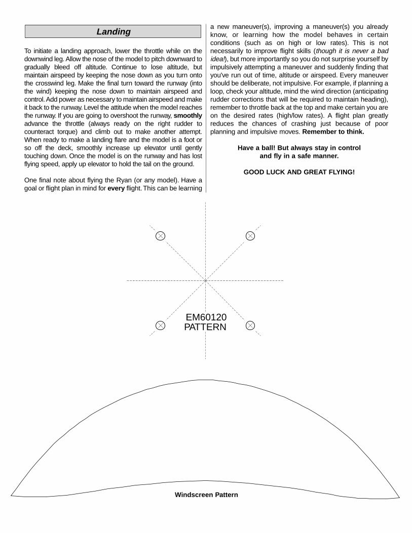
To initiate a landing approach, lower the throttle while on thedownwind leg. Allow the nose of the model to pitch downward togradually bleed off altitude. Continue to lose altitude, butmaintain airspeed by keeping the nose down as you turn ontothe crosswind leg. Make the final turn toward the runway (intothe wind) keeping the nose down to maintain airspeed andcontrol.Add power as necessary to maintain airspeed and makeit back to the runway. Level the attitude when the model reachesthe runway. If you are going to overshoot the runway, smoothlyadvance the throttle (always ready on the right rudder tocounteract torque) and climb out to make another attempt.When ready to make a landing flare and the model is a foot orso off the deck, smoothly increase up elevator until gentlytouching down. Once the model is on the runway and has lostflying speed, apply up elevator to hold the tail on the ground.
One final note about flying the Ryan (or any model). Have agoal or flight plan in mind for every flight.This can be learning
a new maneuver(s), improving a maneuver(s) you alreadyknow, or learning how the model behaves in certainconditions (such as on high or low rates). This is notnecessarily to improve flight skills (though it is never a badidea!), but more importantly so you do not surprise yourself byimpulsively attempting a maneuver and suddenly finding thatyou've run out of time, altitude or airspeed. Every maneuvershould be deliberate, not impulsive. For example, if planning aloop, check your altitude, mind the wind direction (anticipatingrudder corrections that will be required to maintain heading),remember to throttle back at the top and make certain you areon the desired rates (high/low rates). A flight plan greatlyreduces the chances of crashing just because of poorplanning and impulsive moves. Remember to think.
Have a ball! But always stay in controland fly in a safe manner.
GOOD LUCK AND GREAT FLYING!
Landing
EM60120PATTERN
Windscreen Pattern


![DLE-35RA - Hobbico - Hobbico, Inc. - largest U.S ...manuals.hobbico.com/dle/dleg0435-manual.pdfDLE with Manual Choke Main Engine − 2.08lb [947g] ... DLE-35RA Gas Engine with DLE](https://static.fdocuments.in/doc/165x107/5abf1f1d7f8b9a3a428dcf03/dle-35ra-hobbico-hobbico-inc-largest-us-with-manual-choke-main-engine.jpg)


![INSTRUCTION MANUAL - Hobbico, Inc. - largest U.S ...manuals.hobbico.com/flz/flza2102-manual.pdfFLZA2102 SPECIFICATIONS Wingspan: 15.9 in [404mm] Total Length: 15.7 in [399mm] Weight:](https://static.fdocuments.in/doc/165x107/5aa505477f8b9ae7438cd38c/instruction-manual-hobbico-inc-largest-us-specifications-wingspan-159.jpg)


