A Novel Flexible Lane Changing (FLC) Method in Complicated ...
14
J. Appl. Comput. Mech., xx(x) (20xx) 1-14 DOI: 10.22055/JACM.2021.36276.2818 ISSN: 2383-4536 jacm.scu.ac.ir Published online: April 26 2021 A Novel Flexible Lane Changing (FLC) Method in Complicated Dynamic Environment for Automated Vehicles Mohsen Rafat 1 , Shahram Azadi 2 1 PhD. Candidate, Mechanical Engineering Department, K. N. Toosi University of Technology, 19991-43344 Tehran, Iran 2 Associate Professor, Mechanical Engineering Department, K. N. Toosi University of Technology, 19991-43344 Tehran, Iran Received January 08 2021; Revised April 25 2021; Accepted for publication April 25 2021. Corresponding author: S. Azadi ([email protected]) © 2021 Published by Shahid Chamran University of Ahvaz Abstract. Decision making and path planning in case of highly transient dynamics of the surrounding as well as the effect of road condition are the issues that are not completely solved in the previous researches. The goal is to perform a safe and comfortable lane change that includes flexible re-planning capabilities. In this paper, a novel structure for path planning and decision making part of a vehicle automatic lane change has been introduced which comprehensively considers both longitudinal and lateral dynamics of the vehicle. The presented method is able to perform re-planning even in the middle of a lane change maneuver according to new traffic condition. Inclusion of the dynamics of all involved vehicles and providing online performance are the other advantages of the proposed system. The algorithm is simulated and various scenarios are constructed to evaluate the efficiency of the system. The results show that the system has completely acceptable performance. Keywords: Automated driving, Decision making, Lane change (LC), Path planning. 1. Introduction Automated driving has been identified as one of the key technologies to improve road safety and governmental policies were introduced that promote innovations and technologies in this field [1-2]. Also, the preparation of a highly automated vehicle for lane changing maneuver in every condition requires data of surrounding vehicles and other traffic lanes [3-5]. Previous studies on automatic lane change maneuver are basically non-real-time capable except those that have taken into account the effects of surrounding vehicles during the maneuver [6, 7]. While some of them use rule-based methods [8] the others apply gap acceptance theory seeking to optimize LC maneuvers in several aspects including comfort and safety [9]. Researchers have also proposed artificial intelligence-based methods such as game theory in order to address the relationship between LC algorithm and surrounding vehicles and solve common problems in rule-based approaches [10]. Some other studies used special mathematical theories such as Markov chain [11], model-based theory [12] or feature-based inverse reinforcement learning method [13] to improve the ability of automated vehicles in LC maneuvers. In a common category, lane change has been divided in two groups; what-is-called discretionary [14-15] and mandatory lane change. The former comes from the situation that the lane change condition exists and the Ego vehicle doesn’t need to create it as long as staying at the current lane, while the latter reflects the condition that the ego vehicle creates LC condition with acceleration or deceleration to avoid the collision, like this paper. One of the most important issues that automated vehicles face in complex maneuvers such as lane changing, is continuous variation in traffic condition which affects the performance of the automated vehicle during the maneuver [16-17]. This condition has been described as a "Complicated Dynamic Environment". Previous research in the field of lane change, which considered surrounding traffic conditions, have two different aspects; the first one comes from the situation that the developed strategy investigates Ego vehicle’s safety in the lane change maneuver but may bring negative benefit to the following vehicle in the target lane since the Ego vehicle may add turbulence in the traffic flow. The second one reflects a condition to investigate the influence of vehicles’ lane change on the traffic flow [18-20]. This paper focuses on the mandatory lane change and emphasizes that safety for Ego vehicle has more priority rather than its influence on the traffic flow. It means that traffic conditions’ information only will be sent to the developed structure to make a safe decision. In this way, the Ego vehicle disregards the effect of its lane change on the surrounding vehicles which may evoke a certain social dilemma structure [21,22] where the action is beneficial to him but reduce the social efficiency as a whole. In this situation, the most important parameter for collision avoidance is the time that should be consumed to make a new decision and design an alternative trajectory to the new safe target point without any collision. This paper represents a new approach in path planning which can be performed in real-time and in complex dynamic conditions considering the behaviors of other surrounding vehicles. In recent years, many researchers have sought to reduce the effects of human driver error in designing control systems by modeling driver behavior and examining various factors such as mental status, level of consciousness, driver delay, and age conditions [23]. The driver models presented in the papers include various methods such as Stochastic Switched Autoregressive
Transcript of A Novel Flexible Lane Changing (FLC) Method in Complicated ...

J. Appl. Comput. Mech., xx(x) (20xx) 1-14 DOI: 10.22055/JACM.2021.36276.2818
ISSN: 2383-4536 jacm.scu.ac.ir
Published online: April 26 2021
A Novel Flexible Lane Changing (FLC) Method in Complicated
Dynamic Environment for Automated Vehicles
Mohsen Rafat1 , Shahram Azadi2
1 PhD. Candidate, Mechanical Engineering Department, K. N. Toosi University of Technology, 19991-43344 Tehran, Iran
2 Associate Professor, Mechanical Engineering Department, K. N. Toosi University of Technology, 19991-43344 Tehran, Iran
Received January 08 2021; Revised April 25 2021; Accepted for publication April 25 2021.
Corresponding author: S. Azadi ([email protected])
© 2021 Published by Shahid Chamran University of Ahvaz
Abstract. Decision making and path planning in case of highly transient dynamics of the surrounding as well as the effect of road condition are the issues that are not completely solved in the previous researches. The goal is to perform a safe and comfortable lane change that includes flexible re-planning capabilities. In this paper, a novel structure for path planning and decision making part of a vehicle automatic lane change has been introduced which comprehensively considers both longitudinal and lateral dynamics of the vehicle. The presented method is able to perform re-planning even in the middle of a lane change maneuver according to new traffic condition. Inclusion of the dynamics of all involved vehicles and providing online performance are the other advantages of the proposed system. The algorithm is simulated and various scenarios are constructed to evaluate the efficiency of the system. The results show that the system has completely acceptable performance.
Keywords: Automated driving, Decision making, Lane change (LC), Path planning.
1. Introduction
Automated driving has been identified as one of the key technologies to improve road safety and governmental policies were introduced that promote innovations and technologies in this field [1-2]. Also, the preparation of a highly automated vehicle for lane changing maneuver in every condition requires data of surrounding vehicles and other traffic lanes [3-5].
Previous studies on automatic lane change maneuver are basically non-real-time capable except those that have taken into account the effects of surrounding vehicles during the maneuver [6, 7]. While some of them use rule-based methods [8] the others apply gap acceptance theory seeking to optimize LC maneuvers in several aspects including comfort and safety [9]. Researchers have also proposed artificial intelligence-based methods such as game theory in order to address the relationship between LC algorithm and surrounding vehicles and solve common problems in rule-based approaches [10]. Some other studies used special mathematical theories such as Markov chain [11], model-based theory [12] or feature-based inverse reinforcement learning method [13] to improve the ability of automated vehicles in LC maneuvers.
In a common category, lane change has been divided in two groups; what-is-called discretionary [14-15] and mandatory lane change. The former comes from the situation that the lane change condition exists and the Ego vehicle doesn’t need to create it as long as staying at the current lane, while the latter reflects the condition that the ego vehicle creates LC condition with acceleration or deceleration to avoid the collision, like this paper.
One of the most important issues that automated vehicles face in complex maneuvers such as lane changing, is continuous variation in traffic condition which affects the performance of the automated vehicle during the maneuver [16-17]. This condition has been described as a "Complicated Dynamic Environment". Previous research in the field of lane change, which considered surrounding traffic conditions, have two different aspects; the first one comes from the situation that the developed strategy investigates Ego vehicle’s safety in the lane change maneuver but may bring negative benefit to the following vehicle in the target lane since the Ego vehicle may add turbulence in the traffic flow. The second one reflects a condition to investigate the influence of vehicles’ lane change on the traffic flow [18-20]. This paper focuses on the mandatory lane change and emphasizes that safety for Ego vehicle has more priority rather than its influence on the traffic flow. It means that traffic conditions’ information only will be sent to the developed structure to make a safe decision. In this way, the Ego vehicle disregards the effect of its lane change on the surrounding vehicles which may evoke a certain social dilemma structure [21,22] where the action is beneficial to him but reduce the social efficiency as a whole. In this situation, the most important parameter for collision avoidance is the time that should be consumed to make a new decision and design an alternative trajectory to the new safe target point without any collision. This paper represents a new approach in path planning which can be performed in real-time and in complex dynamic conditions considering the behaviors of other surrounding vehicles.
In recent years, many researchers have sought to reduce the effects of human driver error in designing control systems by modeling driver behavior and examining various factors such as mental status, level of consciousness, driver delay, and age conditions [23]. The driver models presented in the papers include various methods such as Stochastic Switched Autoregressive

Mohsen Rafat, Shahram Azadi, Vol. x, No. x, 20xx
Journal of Applied and Computational Mechanics, Vol. xx, No. x, (20xx), 1-14
2
Exogenous [24], the Cerebellar Model Articulation Controller (CMAC) [25], Hidden Markov Model (HMM) [26], Neural Network [27], Bayesian Network [28], Gauss Mixture Model [29], Support Vector Machine [30], which mostly the main criteria for their evaluation is time-consuming and their main discussion is different from the main innovation of this paper. As a comprehensive research, Wang et al., present a linear time-varying model predictive control based on the human driver preferences to address a typical vehicle-to-vehicle (V2V) in lane change scenario with two vehicles traveling on the contiguous lanes in the same direction. In [31], the authors focus on the driver characteristics as effective parameters on the trajectory planning, while the main focus of the presented algorithm in this paper is on investigating the influence of surrounding vehicles’ decision on the planned trajectory and re-planning. Although they presented a valuable control framework for vehicle trajectory re-planning in the lane change maneuvers, they disregarded the changes during the maneuver based on the surrounding vehicles’ decision.
The remainder of the paper is organized as follows: Section 2, contains a description of the proposed novel path planning method with a modified decision-making algorithm. Then, simulation of different maneuvers is presented in section 3 and compared to existing approaches. And finally in section 4 and 5, results and conclusion are presented.
2. Flexible Lane Change Method (FLC)
2.1 Lane change strategy
In general, an automated lane change system consists of three layers. Decision-making unit, as the first layer, indicates the possibility of a lane change based on the information received from sensors. The vehicle trajectory should be generated by the second layer based on the vehicle dynamic constraints and other factors such as safety and comfort. This layer is called path planning unit. Finally, the third layer is responsible to guide the vehicle through the designed trajectory by controlling the steering wheel. Figure 1. shows an illustration of different layers of this system and the one-way top-down format of signal flow between these layers. This figure also presents the system interface to other driver assistance systems.
As discussed in the state of the art, one of the main problems of earlier methods is their inability to consider the transient dynamics of the traffic. This means that as soon as the lane change maneuver begins, any changes in traffic behavior will be ignored and future ego vehicle’s position remains constant. Other methods that could partially solve this problem, suffer from two serious weakness; first, their inability to perform all the calculations in real-time [33], which practically stop them from being used in automotive industry, and second, their inability to find a new point in the target lane and to re-plan the vehicle trajectory if nearby vehicles’ position changes during maneuver [34-37]. The presented algorithm comprehensively covers the decision making and path planning of a fully automated lane change considering both longitudinal and lateral dynamics of the vehicle. In addition, the proposed system takes into account traffic dynamics and prepares the possibility of re-planning and also it can be appropriate for real-time application.
Figure 2. schematically demonstrates different units of the proposed automatic lane change algorithm and their connections. First, based on the information gathered from ego vehicle, traffic vehicles, and road condition, the decision-making-I unit finds out whether a safe lane change is possible and calculates the corresponding maneuver time. These data are then, transferred to path planning unit where several different lane change paths with various initial velocities, accelerations, and maneuver time are already pre-designed off-line and ready to be picked. There are series of intermediate points on the selected path that provides the ability to modify the path in case of traffic condition changes. These new re-planned paths can be shorter or longer than the initial one and might have a different acceleration. After choosing one or more paths based on the maneuver time, the path planning unit feeds these paths to decision-making-II unit where one out of theses nominated paths will be selected based on the minimum lateral acceleration in order to satisfy the best passenger comfort. Finally, the control unit will guide the vehicle through the selected path.
2.2 Decision-Making-I unit
In this paper, the structure of the presented decision-making-I unit is mostly based on previous studies [38-39] with some modifications to improve the performance of the system. Despite the previous decision-making unit which could only give maneuver time at the output, the new developed decision-making unit along with path planning unit are able to calculate both end-point coordinates of lane change path and the maneuver time. Therefore, even for a unique maneuver time, the end point coordinates can be different. This engages the longitudinal dynamics of the ego vehicle in lane change maneuver and therefore, brings more flexibility and freedom. If selected lane change trajectory becomes unsafe during the maneuver due to the changes in traffic condition, the presented algorithm considers different possible new trajectories with or without acceleration to adjust target point with integrated control of gas pedal, brake pedal, and steering wheel.
Fig. 1. Schematic structure of multi-layer lane change controller [32].

A Novel Flexible Lane Changing (FLC) Method in Complicated Dynamic Environment for Automated Vehicles
Journal of Applied and Computational Mechanics, Vol. xx, No. x, (20xx), 1-14
3
Decision Making I
Unit
Ego vehicle data Traffic data
Any changes in
traffic condition
has occurred
Steering angle
Accelerator Module
Brake Control Module
Road Friction
Path Planning Unit
Look-up Table
(Off-line)
Position of the best target point
Decision Making II
Unit
Nominated Paths to the target point
with several times
The best path based on
passenger comfort
Control Unit
No
Yes
Fig. 2. Schematic demonstration of different units of the proposed automatic lane change algorithm and their connections.
Fig. 3. Collision avoidance checking criteria in longitudinal direction (C1, C2 and C3).
In order to find the safe end point and corresponding arrival time in the target lane, more complicated traffic situations are considered in the development of the new algorithm. Both longitudinal and lateral distances to surrounding vehicles are investigated and safety factors, Ci, are derived and later tuned based on human behavior through experimental track tests.
2.2.1 Longitudinal distance
Three factors are discussed here (Fig. 3.) which are considered to obtain safe longitudinal distances between ego vehicle and surrounding vehicles.
In Fig. 3., E represents the ego vehicle, A is the vehicle in front on the same lane and B and D are the vehicles in front and behind on the target lane. The influence of other surrounding vehicles is neglected. At the end of lane change maneuver when ego vehicle reaches the target lane, its distance to vehicles B and D must not be smaller than C1 and C2 respectively. At the starting point of the maneuver, the minimum distance C3 must be considered between vehicles E and A. This value is determined in each maneuver according to the speed of the vehicle as the safety factor. These terms are calculated as follows:

Mohsen Rafat, Shahram Azadi, Vol. x, No. x, 20xx
Journal of Applied and Computational Mechanics, Vol. xx, No. x, (20xx), 1-14
4
2
1 0
( )
2Bx Ex
Ex d
Ex
v vC S v t
a
−= + + (1)
2
2 0 2Ex
Ex d
Eb
vC S v t
a= + +
(2)
3 0 Ex dC S v t= +
(3)
In the above equations, S0, vEx, vBx and aEx are the safe stopping distance, longitudinal velocity of ego vehicle and vehicle B at the end of maneuver, and the maximum deceleration of ego vehicle respectively. Furthermore, td is driver response time which depends on several parameters such as driver physical and mental condition and will be reduced in case when automatic braking systems are used. Moreover, the maximum deceleration is determined based on different conditions such as the actual value of tire-road friction. At the specified time instant, the longitudinal and lateral position of two vehicles are governed by eqs. (4)-(5),
Fig. 4. a) Collision avoidance checking criteria in the lateral direction (C4 – C7). b) Illustration of lateral constraints between ego vehicle and vehicles A (up) and D (down).

A Novel Flexible Lane Changing (FLC) Method in Complicated Dynamic Environment for Automated Vehicles
Journal of Applied and Computational Mechanics, Vol. xx, No. x, (20xx), 1-14
5
2
0 2Ex
B E Ex Brd Ef
Eb
vx x S v t l l
a− = + + + +
(4)
B Ey y= (5)
where, xB and yB indicate the longitudinal and lateral positions of the center of gravity of vehicle B, respectively, and lBr indicates the longitudinal distance from vehicle B‘s center of gravity to the vehicle’s rear. The same, xE and yE show the longitudinal and lateral positions of the center of gravity of ego vehicle, and lEf indicates the longitudinal distance from vehicle E’s center of gravity to the vehicle’s front.
2.2.2 Lateral distance
In Fig. 4(a), the lateral distances which are crucial for collision avoidance are presented. In this figure, C4 and C7 represent the distance between right front corner and right rear corner of vehicle E with the left rear corner of vehicle A, respectively. Also, C5 and C6 show the distances between the left rear corner and left front corner of the ego vehicle and the right front corner of vehicle D. By taking a closer look at the figure, it can be realized that C4 is a stricter constraint than C7. That means if C4 is satisfied, C7 will also be true. The same situation works for the relation between C5 and C6. Therefore, C4 and C5 satisfy all different situations and hence, considered as the main constraints. A larger illustration of the vehicles’ condition in these two cases are shown in Fig. 4(b).
C4 is calculated as follows;
( ) ( ) ( )( ) ( )( )4 M sin P sinA E A M A E P Ey t y t C O t O tθ θ θ θ− = + − + −
(6)
( )2
21
2E E EfO P W L = +
(7)
1tan2
EP
Ef
W
Lθ
− =
(8)
( )2
21M
2A A ArO W L = +
(9)
1tan2
AM
Ar
W
Lθ
− =
(10)
( )( )
( )( )tan( )
yE tEE
E xE
vy tt
x t vθ
∂= =∂
(11)
( )( )
( )( )tan( )
yA tAA
A xA
vy tt
x t vθ
∂= =∂
(12)
( ) ( )
( ) ( )( )22
sin( )yE t
E
xE yE t
vt
v v
θ =
+ (13)
( )( ) ( )( )
22cos( ) xE
E
xE yE t
vt
v v
θ =
+ (14)
Equation (6) expresses the lateral distance between the ego vehicle and vehicle A at the moment that their longitudinal
coordinates coincide. In this equation, yA(t) and yE(t) indicate the lateral position of the center of gravity of vehicles A and E,
respectively. EO P and AO M are imaginary lines that connect the center of gravity of vehicles to the points P and M. 'P is the
angles between OEP and longitudinal axis of the ego vehicle while 'O presents the angles between OEM and longitudinal axis of
vehicle A. In the above equations which have been used to calculate the minimum amount of C4 to maintain safety, LEf and LAr
represent the longitudinal distance between the gravity center of vehicle E to its front and the longitudinal distance of vehicle A’s
center of gravity to its rear. WE and WA are the width of ego vehicle and vehicle A. The condition for longitudinal coincidence of
points P and M can be stated by,
( )( ) ( )( )OM cos OPcosA M A E P EX t X tθ θ θ θ− − = + −
(15)
The driver of vehicle D is asked to activate the ACC system before starting the maneuver, so the behavior of vehicle D is controlled by the automatic system and the possibility of sudden velocity change is almost negligible and hence a two-second law [40] is used instead of the conservative method in eq. (2). Therefore, C5 is calculated as follow;
( ) ( ) ( )( ) ( )( )5 N sin Q sinE D D N D E Q Ey t y t C O t O tθ θ θ θ− = + − + − (16)

Mohsen Rafat, Shahram Azadi, Vol. x, No. x, 20xx
Journal of Applied and Computational Mechanics, Vol. xx, No. x, (20xx), 1-14
6
2E D Dx Er DfX X v l l− = + + (17)
( )2
21Q
2E E ErO W L = +
(18)
1tan2
EQ
Er
W
Lθ
− =
(19)
( )2
21N
2D D DfO W L = +
(20)
1tan2
DN
Df
W
Lθ
− =
(21)
In the above equations, XD and yD(t) represent the longitudinal and lateral coordinates of vehicle D where VDx indicates vehicle
D's longitudinal velocity at the end of the maneuver. In addition, EO Q and DO N show the distances between the center of
gravity of ego vehicle and Q and the center of gravity of Vehicle D to point N, respectively. 'Q is the angles between OEQ and
longitudinal axis of the ego vehicle while θD presents the angles between ODN and longitudinal axis of vehicle D. Moreover, LEr and
LDf represent the longitudinal distance between the gravity center of vehicle E to its rear and the longitudinal distance of vehicle
D’s center of gravity to its front. WD is the width of vehicle D.
Applying all above equations, the presented decision-making algorithm calculates the possible maneuver time. In the end,
this information will be sent to path planning unit in order to select a safe trajectory from the trajectories that have been
designed off-line. The required parameters to calculate the maneuver time based on the above equations are listed in Table 1.
2.2.3 Road test
To determine the parameters of the proposed algorithm based on human driver behavior, various road tests have been carried out. As shown in Fig. 5, all vehicles were equipped with data gathering and measurement equipment, GPS, radar, and vehicle to vehicle communication system. All data were recorded and synchronized at a high sampling rate and in real-time. The specifications for all of the sensors used in the tests are presented in Table 2.
In this study, the position of each vehicle at the beginning and end point of the maneuver was tracked during three different maneuver. The first maneuver uses two vehicles. The “target” vehicle travels at a constant velocity of 80 km/h by activating the ACC system. At first, the EGO vehicle maintains a distance of 70 m behind the target vehicle. Then when the maneuver starts, the EGO vehicle begins to approach the target vehicle at a constant velocity of 100 km/h. There are no other cars on the road, and the driver can perform the lane change maneuver without disturbance. The driver is instructed to make the lane change whenever he prefers and only based on his own driving style.
Three different vehicles are needed for the second maneuver. The EGO vehicle is traveling behind a target vehicle (target 1) in the same line. Both vehicles have activated the ACC system and are traveling at a constant velocity of 100km/h in the similar lane. At this moment, another target vehicle (target 2) is traveling at a speed of 120 km/h in the target lane and overtakes the EGO vehicle. The driver of the EGO vehicle is instructed to perform the lane change when Target 2 passes and as soon as he feels safe.
Finally, in the third maneuver, both target 1 and target 2 are moving in the target lane with a constant velocity of 120 km/h. The distance between these two cars is set to 50 m. The ego vehicle is traveling far in front of these two cars in the initial lane and with the speed of 100 km/h. With the beginning of the maneuver, two target vehicles approach the ego vehicle. The driver of the ego vehicle is asked to do a cut-in maneuver in the appropriate time.
Fig. 5. Test vehicles, sensors, data gathering and equipment.
Table 1. Required parameters.
Parameter Value Parameter Value
WA 1.65 (m) WE 1.65 (m)
abD 9.81µ (m/s2) td 0.5 (s)
S0 2 (m) abE 9.81µ (m/s2)
WD 1.65 (m)

A Novel Flexible Lane Changing (FLC) Method in Complicated Dynamic Environment for Automated Vehicles
Journal of Applied and Computational Mechanics, Vol. xx, No. x, (20xx), 1-14
7
Table 2. The specifications for all of the sensors used in the tests.
Sensor model Vehicle
Sensor type Manufacturer Sampling rate Accuracy 640 i Passat
ADMA-G X X Inertial Measurement Unit (IMU) GeneSys Elektronik 2000Hz 1mg
DAWE-CAM X X Camera DEWETRON 30 fps -
WEB-CAM X Camera Microsoft Commercial 30fps -
Microphone X Microphone PCB Piezotronics 2000Hz -
DAQ_1 X DEWE2-M4 DEWETRON 2000Hz 1mg
DAQ_2 X DEWE 510 DEWETRON 2000Hz 1mg
Figure 6(a) shows the relative lateral positions of two vehicles in relation to their relative longitudinal positions for different drivers during the first maneuver. The red oval indicates that the test participants usually maintain a distance between 35 and 55 meters to the preceding vehicle at the starting moment of the maneuver (C3). In addition, at the moment when the ego vehicle reaches the target vehicle, there is a lateral distance of 3.6 to 4.2 meter between the two vehicles. Hence, we derive the value of 3.75 for the C4, which is indeed the lane width.
Figure 6(b) shows the relative distance between the ego vehicle and the two target vehicles at the starting moment of the second maneuver. As is evident, the volunteer drivers keep more longitudinal distance with the vehicle in the same lane than with the vehicle in the target lane. This distance is usually in the range of 40 to 55 meters. Therefore, the amount equal to 47(m) (i.e. the average value for this range) was selected as a value for C1.
Figure 6(c) shows the distance between the ego vehicle and the two target vehicles at the end of the third maneuver. The black dots show the position of the ego vehicle, the red dots show the following target vehicle position, and the green dots indicate the position of the preceding target vehicle. According to this figure, during a cut-in maneuver, drivers keep more distance from the following vehicle than from the preceding vehicle. The reason might be that the drivers believe they can more effectively manage a potential emergency situation created by the car in front than one created by the car behind. Based on the result, C5 and C2 were set to 3.75 and 35, respectively.
(a)
(b)

Mohsen Rafat, Shahram Azadi, Vol. x, No. x, 20xx
Journal of Applied and Computational Mechanics, Vol. xx, No. x, (20xx), 1-14
8
(c)
Fig. 6. a) Relative lateral and longitudinal positions of two vehicles in the first maneuver. b) Relative distance between the ego vehicle and the two target vehicles at the starting moment of the second maneuver. c) Distance between the ego vehicle and the two target vehicles at the end of third
maneuver.
The above tests have been performed in different road conditions with different positions of the surrounding vehicles to extract the considered longitudinal and lateral distances to avoid collisions for each volunteer drivers. Then, safe time for performing the lane change maneuver has been calculated with the help of above mentioned relations. In this algorithm, the coefficient of friction is considered in a way that in the first phase of decision-making, it can be changed at each stage to determine the optimal time for each safe target point. Regarding this change, safe longitudinal and lateral distances for performing the maneuvers will also change according to the coefficient of friction. The authors have practically studied the coefficient of friction and its effects on vehicle dynamics by considering the most aggressive lane change maneuver to obtain the minimum required time. On the other hand, the same coefficient of friction (the coefficient of friction in the decision-making unit) has been considered as a specific input for the tracking control unit. Since this paper focuses on the lane change maneuver, the coefficient of friction’s estimator has been omitted. Considering the coefficient of friction means that by changing the coefficient of friction’s value, the Ci values obtained by the algorithm will change but this paper does not provide any coefficient of friction’s estimator. It is assumed that the coefficient of friction in the presented maneuver is specified and the simulated maneuver in this paper is applied on dry road. By tracking the position of each vehicle at the start and end point of the maneuver and after processing the results of practical tests with different drivers and selected distances by them, Ci values are adjusted based on the human driver behavior and is placed in the above relations to calculate the appropriate time.
2.3 Path planning unit
The information about the possibility of performing a lane change as well as the maneuver time is prepared by decision-making-I unit. Path-planning unit designs several safe trajectories considering vehicle dynamics. The novelty of presented path planning unit is its ability for re-planning in the middle of lane change maneuver even in complicated traffic condition based on updated information from decision-making-I unit.
In the proposed method, a 5th order polynomial function has been applied for trajectory planning. The differential evolution (DE) optimization method has been used to find the coefficient of the polynomial considering physical constraints of ego vehicle. The DE, as one of the most powerful and popular evolutionary algorithms, has a good performance in discontinuous, time-variant and noisy problems. In addition, the DE allows inclusion of the constraints between the parameters and performs global optimization without getting stuck in local minima [41-43].
Based on experiments, for the current problem with high calculation effort, optimization methods are very time-costly and cannot be applied for real-time purposes. In order to solve the problem, the strategy of designing the lane change is defined in such a way that the path planning unit works off-line. For that first, all possible lane change trajectories for different situations are designed. Then, all the designed paths are placed in a look-up table while a labels is assigned to each of them. Each label indicates the maneuver time. When this parameter is defined in the decision-making-I unit, the desired corresponding path or paths will be chosen from the look-up table. In this way, the time-consuming procedure of optimizing a lane change trajectory will be transferred to a real-time process of choosing a trajectory and hence, automatic lane change can be performed in real-time. The concept structure of the path planning unit is explained in details as follows;
Based on the vehicle dynamics and road condition, there is a quickest possible lane change maneuver in which the vehicle remains stable. It is called the most aggressive lane change trajectory and has been shown in red with the end-point named Acritical in Fig. 7(a). It is obvious that any point to the left side of Acritical cannot be selected since it is either not accessible or cause an instability in ego vehicle. Any other point on the right side of Acritical is feasible and theoretically can be nominated as the end-point of the lane change trajectory. As it can be seen, n different points are considered in Fig. 7(a). Three different trajectories with constant velocity (a=0 m/s2), positive acceleration (a=+1 m/s2), and negative acceleration (a=-1 m/s2) will be designed between the start point and each of these end-points applying DE optimization method on a fifth order polynomial equation. Therefore, several different lane change paths with different maneuver time are in hand. In order to find the lane change path(s), it is enough to know the maneuver time.

A Novel Flexible Lane Changing (FLC) Method in Complicated Dynamic Environment for Automated Vehicles
Journal of Applied and Computational Mechanics, Vol. xx, No. x, (20xx), 1-14
9
(a)
(b)
Fig. 7. a) Different possible end-points and corresponding trajectories for lane change maneuver. b) Sample scenario.
As discussed earlier, the traffic condition might vary during the lane change maneuver causing the initial designed path not to be safe anymore. To be able to act properly to the changes, some mid-points have been considered for each of the initial paths. At each of these mid-points, the same procedure has been repeated to find out the most aggressive trajectory and other feasible trajectories on the right side of it. As a sample scenario, imagine based on the data prepared by decision-making-I unit the path which ends to Am with a constant velocity fulfils the requirements (Fig. 7a). The tracking control has started to guide the ego vehicle through the desired path as shown in Fig. 7(b). A sudden change in traffic condition makes the current path unsafe. Now based on the pre-designed trajectories, the decision making unit has the possibility to choose another end-point from Bcritical to Bq.
All designed trajectories are obtained from fifth-order polynomial equations. The constraints of this equation are determined according to the vehicle’s physical limitations. These constraints include: the end and beginning point of the trajectory, vehicle direction at the start and end of the trajectory, the maximum lateral acceleration and the continuity of re-planned trajectories with the previous trajectory. After determining the constraints of the problem, all the optimal safe trajectories are obtained using DE optimization algorithm. One of the important constraints of this equation is the maximum lateral acceleration limitation, which ensures the feasibility of the trajectories. In fact, all the provided trajectories for the control unit are feasible in terms of vehicle dynamics and satisfy the physical limitations of the problem.
The number of end-points and space between them as well as the number of mid-points considered on each initial path is adjustable. As the number of end-points and mid-points increases, the algorithm becomes more flexible and reliable. In this way the conventional format of one-way top-down signal flow between layers of the automatic lane change system has been changed. In addition, this discretization of a continuous space enables the algorithm to works in real-time.
2.4 Decision-Making-II unit
After the definition of the safe target point in decision-making-I unit, all possible lane change paths with different maneuver time and acceleration which were previously designed off-line and exist in the path planning unit will be delivered to decision-making-II. This unit is able to pick one of these nominated paths as the desired lane change trajectory based on different parameters such as passenger comfort, fuel consumption, and safety. In this paper, to select the best trajectory between acceptable ones (target point and arrival time determined by path planning and decision-making-I units as the acceptable trajectories factors), minimum lateral acceleration is used as decision factor.
3. Simulation
3.1 Preparing the look-up table
In this section, required maneuvers for preparing the path planning unit and turning it into a look-up table are shown. In this paper, six more points with the distance interval of 10 (m) are considered to the right side of the most aggressive trajectory. In addition, three different trajectories with constant velocity (a=0 m/s2), positive acceleration (a=+1 m/s2), and negative acceleration (a=-1 m/s2) are designed between the start point and each of these end-points applying DE optimization method on a fifth-order polynomial equation. For a better representation, the results of a sample scenario are explained here as follows; In this simulated driving scenario in a highway with the velocity of 90 (km/h) and based on the ego vehicle dynamics and road friction, the most aggressive lane change took around 2.98 (s) and during this time the ego vehicle took 70 (m) in the longitudinal direction (see Fig. 8(a)). For a clearer presentation, only the trajectories with the acceleration equal to -1(m/s2) to all other points are demonstrated in this figure. For each presented path, there were some mid-points where the same procedure would be repeated to find out the most aggressive trajectory and other feasible trajectories on the right side of it as the re-planning paths. To clarify the design of re-planed trajectories, the initial path in Fig. 8(a) which had a maneuver time equal to 4.87 (s) and a longitudinal distance equal to 110 (m) was chosen as a sample and the re-planned paths which were originated from the first mid-point located on this trajectory were demonstrated in Fig. 8(b). This process was repeated until all possible initial paths and re-planned paths with different initial condition and road friction were designed to form the look-up table.

Mohsen Rafat, Shahram Azadi, Vol. x, No. x, 20xx
Journal of Applied and Computational Mechanics, Vol. xx, No. x, (20xx), 1-14
10
3.2 Scenario design
In this section, a maneuver in a highly dynamic condition has been presented in order to evaluate the performance of the proposed method. This sample scenario simulates a critical situation within which the automatic lane change system has to redesign the desired path two times. In addition, the velocity of ego vehicle has to change during the maneuver. Hence, this scenario is suitable to evaluate the performance of the system.
The ego vehicle (E) is surrounded by three traffic vehicles. Vehicle A is located in front of ego vehicle in the same lane and vehicles B and D are located in front and behind the ego vehicle in the target lane, respectively. Ego vehicle has a constant velocity equal to 90 (km/h) and its longitudinal distance at the beginning of the maneuver with vehicles A, B, and D is 50, 170 and 60 meters, respectively. The automatic lane change system is asked to perform a lane change maneuver. After 1.4 (s) from the beginning of the lane change maneuver, vehicle B brakes down with an acceleration equal to a_B1 = -0.7 (m/s2) due to changes in the traffic flow. After 0.9 (s) of driving based on the new condition, vehicle B again decelerates and achieves an acceleration equal to a_B2 = -1.1 and makes the previous lane change end point unsafe. The automatic lane change system is expected to show proper reactions to these changes in the traffic environment.
(a)
(b)
Fig. 8. a) Possible trajectories for LC maneuver with different target point. b) Possible trajectories for re-planning in LC maneuver.
Fig. 9. Surrounding vehicles’ positions in: a) The first section of maneuver. b) The second section of maneuver. c) The third section of maneuver.

A Novel Flexible Lane Changing (FLC) Method in Complicated Dynamic Environment for Automated Vehicles
Journal of Applied and Computational Mechanics, Vol. xx, No. x, (20xx), 1-14
11
(a)
(b)
Fig. 10. a) LC trajectory for the first maneuver and alternative trajectories to avoid collision. b) Real path taken by ego vehicle in comparison with the designed lane change trajectory.
3.3 Scenario implementation
Although, major researches implement a linear dynamic model [44-46], in this paper IPG CarMaker as one of the best platforms for simulating vehicle dynamics and control has been applied to implement the maneuvers. Figure 9 presents an illustration of surrounding vehicles positions to prove the presented method real-time ability in three parts of maneuver. The high performance of IPG CarMaker in implementing driving scenarios for both off-line and real-time maneuver has been proved [47-48]. IPG CarMaker provides the parametric model with a variety of subsystems such as powertrain, braking, suspension and steering systems with several tire and driver models which can be determined for every special test scenario. In addition, the connection between IPG CarMaker and MATLAB/SIMULINK along with C-language codes capabilities are the main reasons for choosing this dynamic simulation software in this paper.
4. Results and discussion
The designed scenario described in section 3.2, is implemented and the results are presented in this section. Based on the initial information gathered, decision-making units together with path planning unit consider a lane change trajectory which has the specifications shown in Fig. 10(a) (dash line). As it can be seen, this maneuver will take 6.43 (s) and within this time the ego vehicle will take 140 (m) in longitudinal direction with a constant acceleration equal to -1 (m/s2). This trajectory is chosen between all other possible trajectories because it prepares better passenger comfort (lower lateral acceleration) in comparison to other trajectories available in path planning unit.
After 1.4 (s) from the beginning of the lane change maneuver and when vehicle B brakes down, the decision-making-I unit realizes that point p1 (end point in the selected trajectory) is not safe anymore and choose a new maneuver time equal to 5 (s). This new information is sent to the path planning unit and the decision-making-II unit picks up the re-planned trajectory as presented in Fig. 10(a) (dash-dot line). As it can be seen, the new trajectory’s end point (q1) is located 20 (m) behind p1. The ego vehicle must take this re-planned trajectory with a constant velocity.
After 0.9 (s) of driving on the re-planned trajectory, vehicle B again slows down and makes q1 an unsafe target point. The process of finding another maneuver time and then selecting a new desired path is repeated and finally, the trajectory is shown in solid line in Fig. 10(a) is elected for the rest of the lane change maneuver. As can be seen, the point m1 has been chosen as the final target point, and ego vehicle must take this path with a constant acceleration equal to +1 (m/s2).
In order to close the loop and track the behavior of the ego vehicle, simple PID controllers are added to the model which control the steering angle, gas, and brake pedals. Figure 10(b) illustrates the real path taken by ego vehicle and compares it with the desired lane change trajectory designed by the proposed automatic lane change system. Important dynamic parameters of the ego vehicle during the lane change maneuver have been demonstrated in Fig. 11.
Mohsen Rafat, Shahram Azadi, Vol. x, No. x, 20xx
Journal of Applied and Computational Mechanics, Vol. xx, No. x, (20xx), 1-14
12
(a)
(b)
(c)
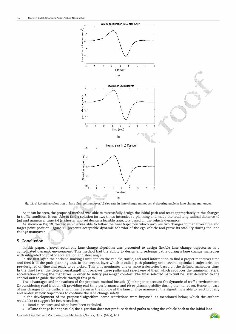
Fig. 11. a) Lateral acceleration in lane change maneuver. b) Yaw rate in lane change maneuver. c) Steering angle in lane change maneuver.
As it can be seen, the proposed method was able to successfully design the initial path and react appropriately to the changes in traffic condition. It was able to find a solution for two times intensive re-planning and made the total longitudinal distance 40 (m) and maneuver time 3.4 (s) shorter and yet design a feasible trajectory based on the vehicle dynamics.
As shown in Fig. 10, the ego vehicle was able to follow the final trajectory, which involves two changes in maneuver time and target point position. Figure 11. presents acceptable dynamic behavior of the ego vehicle and prove its stability during the lane change maneuver.
5. Conclusion
In this paper, a novel automatic lane change algorithm was presented to design flexible lane change trajectories in a complicated dynamic environment. This method had the ability to design and redesign paths during a lane change maneuver with integrated control of acceleration and steer angle.
In the first layer, the decision-making-I unit applies the vehicle, traffic, and road information to find a proper maneuver time and feed it to the path planning unit. In the second layer which is called path planning unit, several optimized trajectories are pre-designed off-line and ready to be picked. This unit nominates one or more trajectories based on the defined maneuver time. In the third layer, the decision-making-II unit receives these paths and select one of them which produces the minimum lateral acceleration during the maneuver in order to satisfy passenger comfort. The final selected path will be later delivered to the control unit to guide the vehicle through this path.
The advantages and innovations of the proposed method include (1) taking into account the dynamic of traffic environment, (2) considering road friction, (3) providing real-time performance, and (4) re-planning ability during the maneuver. Hence, in case of any changes in the traffic environment even in the middle of the lane change maneuver, the algorithm is able to react properly and re-design new trajectories to continue the lane change safety.
In the development of the proposed algorithm, some restrictions were imposed, as mentioned below, which the authors would like to suggest for future studies;
Road curvatures and slope have been excluded. If lane change is not possible, the algorithm does not produce desired paths to bring the vehicle back to the initial lane.

A Novel Flexible Lane Changing (FLC) Method in Complicated Dynamic Environment for Automated Vehicles
Journal of Applied and Computational Mechanics, Vol. xx, No. x, (20xx), 1-14
13
A nonlinear controller such as sliding mode or fuzzy controller can increase the tracking ability. Providing predictive algorithms to predict future movements of the surrounding vehicles and using them to determine
safe target points, along with the presented algorithm in this paper, can provide a comprehensive decision-making algorithm to determine time and safe points at all moments of the maneuver.
A comprehensive simulation approach to evaluate the performance of the system in various traffic situations is a crucial outlook for the study.
Author Contributions
M. Rafat planned the scheme, initiated the project, suggested the methodology and the main contribution, wrote the original draft and prepared the revised version as well as answers for the reviewers’ comments; S. Azadi cooperated in planning the scheme, preparing scientific answer to the reviewers’ comments, and supervised the whole project. The manuscript was written through the contribution of all authors. All authors discussed the results, reviewed, and approved the final version of the manuscript.
Conflict of Interest
The authors declared no potential conflicts of interest with respect to the research, authorship, and publication of this article.
Funding
The authors received no financial support for the research, authorship, and publication of this article.
References
[1] Pourmahmoudi, A., Ghaffari, A., Javadi, M., and Khodayari, A., A predictive model of discretionary lane change behavior considering human factors in the framework of time parameters, Proceedings IMechE Part D: Journal of Automobile Engineering, 234(4), 2019, 1-13. [2] Sazgar, H., Azadi, Sh., Kazemi, R., Trajectory planning and combined control design for critical high-speed lane change maneuvers, Proceedings of the Institution of Mechanical Engineers, Part D: Journal of Automobile Engineering, 234(2-3), 2019, 823-839. [3] Tang, J., Liu, F., Zhang, W., et al., Lane-changes prediction based on adaptive fuzzy neural network, Expert Systems with Applications, 91, 2018, 452–463. [4] Tanimoto, J., Fundamentals of Evolutionary Game Theory and its Applications, Springer, 2015. [5] Li, L., Gan, J., Ji, X., Qu, X., Ran, B., Dynamic Driving Risk Potential Field Model Under the Connected and Automated Vehicles Environment and Its Application in Car-Following Modeling, IEEE Transaction on Intelligent Transportation Systems, 2020, 1-20, DOI: 10.1109/TITS.2020.3008284. [6] Li, F., Li, G., LI, X., Research on Lane Change Timing Model Considering the Influence of Four Surrounding Vehicles, IEEE Conference and Expo Transportation Electrification Asia-Pacific (ITEC Asia-Pacific), Beijing, China, 2014. [7] Ruina, D., Jieyun, D., Bo, S., Qichang, Y., Yuanmu, T., Keqiang, L., A Lane Change Warning System Based on V2V Communication, 17th International Conference on Intelligent Transportation Systems (ITSC), Qingdao, China, 2014. [8] Toledo, T., Koutsopoulos, H.N., Ben-Akiva, M., Integrated driving behavior modeling, Transportation Research Part C: Emerging Technologies, 15(2), 2007, 96–112. [9] Nobukawa, K., Bao, Sh., LeBlanc, D.J., Zhao, D., Peng, H., Pan, Ch., Gap Acceptance during Lane Changes by Large-Truck Drivers - An Image-Based Analysis, IEEE Transaction on Intelligent Transportation Systems, 17(3), 2016, 772-781. [10] Wang, M., Hoogendoorn, S.P., Daamen, W., Van Arem, B., Happee, R., Game theoretic approach for predictive lane-changing and car-following control, Transportation Research Part C: Emerging Technologies, 58, 2015, 73–92. [11] Kretzschmar, H., Kuderer, M., Burgard, W., Learning to predict trajectories of cooperatively navigating agents, IEEE International Conference on Robotics and Automation (ICRA), Hong Kong, China, 2014. [12] Bae, H., Kang, Y., Decision Making Methods Based on Nonlinear Model Predictive Control for Emergency Collision Avoidance in Complex Situations, 14th International Conference on Control, Automation and Systems (ICCAS), Gyeonggi-do, Korea (South), 2014. [13] Kuderer, M., Gulati, S., Burgard, W., Learning driving styles for autonomous vehicles from demonstration, IEEE International Conference on Robotics and Automation (ICRA), Seattle, WA, USA, 2015. [14] Wang, X., Wen, J., Nan, Z., Shi, J., Xu, L., Zheng, N., A General and Practical Path Planning Framework for Autonomous Vehicles, IEEE 19th International Conference on Intelligent Transportation Systems (ITSC), Rio de Janeiro, Brazil, 2016. [15] Li, L., Gan, J., Zhou, K., Qu, X., Ran, B., A novel lane-changing model of connected and automated vehicles: Using the safety potential field theory, Physica A: Statistical Mechanics and its Applications, 559, 2020, 125039. [16] Tanimoto, J., Evolutionary Games with Sociophysics: Analysis of Traffic Flow and Epidemics, Springer, 2019. [17] Dixit, S., Fallah, S., Montanaro, U., et al., Trajectory planning and tracking for autonomous overtaking: state-of-the-art and future prospects, Annual Reviews in Control, 45, 2018, 76–86. [18] Kukida, Sh., Tanimoto, J., Hagishima, A., Analysis of the influence of lane changing on traffic-flow dynamics based on the cellular automaton model, International Journal of Modern Physics C, 22(3), 2011, 271-281. [19] Tanimoto, J., Fujiki, T., Wang, Zh., Hagishima, A., Ikegaya, N., Dangerous drivers foster social dilemma structures hidden behind a traffic flow with lane changes, Journal of Statistical Mechanics: Theory and Experiment, 2014, P11027. [20] Tanimoto, J., Nakamura, K., Social dilemma structure hidden behind traffic flow with route selection, Physica A: Statistical Mechanics and its Applications, 459, 2016, 92-99. [21] Nakata, M., Yamauchi, A., Tanimoto, J., Hagishima, A., Dilemma game structure hidden in traffic flow at a bottleneck due to a 2 into 1 lane junction, Physica A, 389, 2010, 5353-5361. [22] Iwamura, Y., Tanimoto, J., Complex traffic flow that allows lane-changing and hampering intrinsically contains social-dilemma structures, Journal of Statistical Mechanics: Theory and Experiment, 2018, 023408. [23] Xu, G., Liu, L., Song, Z., Ou, Y., Generating lane change trajectories using the Dynamic Model of Driving Behavior, International Conference on Information and Automation, China, 2011. [24] Celik, O., Ertugrul, S., Predictive human operator model to be utilized as a controller using linear, neuro-fuzzy and fuzzy-ARX modeling techniques, Engineering Applications of Artificial Intelligence, 23(4), 2010, 595-603. [25] Jiang, Y., Yang, Ch., Wang, M., Wang, N., Liu, X., Bioinspired control design using cerebellar model articulation controller network for omnidirectional mobile robots, Advances in Mechanical Engineering, 10(8), 2018, 1–14. [26] Akai, N., Hirayama, T., Morales, L., Akagi, Y., Liu, H., Murase, H., Driving Behavior Modeling Based on Hidden Markov Models with Driver’s Eye-Gaze Measurement and Ego-Vehicle Localization, IEEE Intelligent Vehicles Symposium, France, 2019. [27] Li, A., Jiang, H., Zhou, J., Zhou, X., Implementation of human-like driver model based on recurrent neural networks, IEEE Access; Digital Object Identifier, 2019. [28] Song, R., Driver intention prediction using model-added Bayesian network, Proceedings of the Institution of Mechanical Engineers, Part D: Journal of Automobile Engineering, 235(5), 2020, 1236-1244. [29] Wang, W., Xi, J., Hedrick, K., A Learning-Based Personalized Driver Model Using Bounded Generalized Gaussian Mixture Models, IEEE Transactions on Vehicular Technology, 68(12), 2019, 11679-11690. [30] Tharwat, A., Gabel, T., Parameters optimization of support vector machines for imbalanced data using social ski driver algorithm, Neural

Mohsen Rafat, Shahram Azadi, Vol. x, No. x, 20xx
Journal of Applied and Computational Mechanics, Vol. xx, No. x, (20xx), 1-14
14
Computing and Applications, 32, 2020, 6925–6938. [31] Wang, J., Wang, J., Wang, R., Hu, C., A Framework of Vehicle Trajectory Replanning in Lane Exchanging With Considerations of Driver Characteristics, IEEE Transactions on Vehicular Technology, 66(5), 2017, 3583-3596. [32] Samiee, S., The design of driver drowsiness detection system based on vehicle-driver interaction and controlling the vehicle autonomously, Ph.D. Thesis, Department of Mechanical Engineering, K. N. Toosi University of Technology, 2015. [33] Yoon, S., Kum, D., The Multilayer Perceptron Approach to Lateral Motion Prediction of Surrounding Vehicles for Autonomous Vehicles, IEEE Intelligent Vehicles Symposium (IV), Gothenburg, Sweden, 2016. [34] Liu, Y., Wang, X., Li, L., Cheng, Sh., Chen, Zh., A Novel Lane Change Decision-Making Model of Autonomous Vehicle Based on Support Vector Machine, IEEE Access, 7, 2019, 26543-26550. [35] Cao, P., Xu, Zh., Fan, Q., Liu, X., Analysing driving efficiency of mandatory lane change decision for autonomous vehicles, IET Intelligent Transport Systems, 13(3), 2018, 506-514. [36] Zhao, M., Wang, Sh., Sun, D., Wang, X., A Car-Following Model Considering Preceding Vehicle's Lane-Changing Process, IEEE Access, 7, 2019, 89913-89923. [37] Liu, X., Liang, J., Xu, B., A Deep Learning Method for Lane Changing Situation Assessment and Decision Making, IEEE Access, 7, 2019, 133749–133759. [38] Samiee, S., Azadi, Sh., Kazemi, R., Eichberger, A., Rogic, B., Semmer, M., Performance evaluation of a novel vehicle collision avoidance lane change algorithm, Advanced Microsystems for Automotive Applications, Berlin, Germany, 2015. [39] Samiee, S., Azadi, S., Kazemi, R., et al., Towards a decision making algorithm for automatic lane change maneuver considering traffic dynamics, PROMET, 28(2), 2016, 91–103. [40] Jula, H., Kosmatopoulos, EB., Ioannou, PA., Collision Avoidance Analysis for Lane Changing and Merging, IEEE Transactions on Vehicular Technology, 49(6), 2000, 2295-2308. [41] Hu, Z., Xiong, S., Su, Q., Zhang, X., Sufficient Conditions for Global Convergence of Differential Evolution Algorithm, Journal of Applied Mathematics, 2013(1), 2013, 193196. [42] Ali, I., Essam, D., Kasmarik, K., A novel design of differential evolution for solving discrete traveling salesman problems, Swarm and Evolutionary Computation, 52, 2020, 100607. [43] Kadzinski, M., Tomczyka, M.K., Słowinski, R., Preference-based cone contraction algorithms for interactive evolutionary multiple objective optimization, Swarm and Evolutionary Computation, 52, 2020, 100602. [44] Rasekhipour, Y., Khajepour, A., Chen, S., et al., A potential field-based model predictive path-planning controller for autonomous road vehicles, IEEE Transactions on Intelligent Transportation Systems, 18(5), 2017, 1255–1267. [45] Suh, J., Chae, H., Yi, K., Stochastic model predictive control for lane change decision of automated driving vehicles, IEEE Transactions on Vehicular Technology, 67(6), 2018, 4771-4782. [46] Cai, J., Jiang, H., Chen, L., et al., Implementation and development of a trajectory tracking control system for intelligent vehicle, Journal of Intelligent and Robotic Systems, 94, 2019, 251–264. [47] Olofsson, M., Pettersson, J., Parameterization and Validation of Road and Driver Behavior Models for CarMaker Simulations and Transmission HIL-Rig, Master Thesis, Department of Applied Mechanics, Division of Vehicle Engineering and Autonomous Systems and Chalmers University of Technology, 2015. [48] Cao, P., Modeling Active Perception Sensors for Real-Time Virtual Validation of Automated Driving Systems, Ph.D. Thesis, Department of Mechanical Engineering, Technical University of Darmstadt, Germany, 2017.
ORCID iD
Mohsen Rafat https://orcid.org/0000-0002-1089-1244 Shahram Azadi https://orcid.org/0000-0002-5817-9838
© 2021 Shahid Chamran University of Ahvaz, Ahvaz, Iran. This article is an open access article distributed under the terms and conditions of the Creative Commons Attribution-NonCommercial 4.0 International (CC BY-NC 4.0 license) (http://creativecommons.org/licenses/by-nc/4.0/).
How to cite this article: Rafat M., Azadi S. A Novel Flexible Lane Changing (FLC) Method in Complicated Dynamic Environment for Automated Vehicles, J. Appl. Comput. Mech., xx(x), 20xx, 1–14. https://doi.org/10.22055/JACM.2021.36276.2818
Publisher’s Note Shahid Chamran University of Ahvaz remains neutral with regard to jurisdictional claims in published maps and institutional affiliations.