A NEW METHOD TO DETERMINE in situ GROUND THERMAL CONDUCTIVITY IN BOREHOLE HEAT EXCHANGERS
18
• Purpose • Probe construction • Field and laboratory measurements • Data processing, applicational example A NEW METHOD TO DETERMINE in situ GROUND THERMAL CONDUCTIVITY IN BOREHOLE HEAT EXCHANGERS Ernst Rohner 1) , Ladislaus Rybach 1,2) , Ulrich Schärli 3) , Thomas Kohl 1) 1) GEOWATT AG Zürich, 2) Inst. für Geophysik ETH Zürich, 3) Dr. U. Schärli – Geologie + Geophysik, Zürich
-
Upload
wilma-herrera -
Category
Documents
-
view
29 -
download
1
description
A NEW METHOD TO DETERMINE in situ GROUND THERMAL CONDUCTIVITY IN BOREHOLE HEAT EXCHANGERS. Ernst Rohner 1) , Ladislaus Rybach 1 ,2 ) , Ulrich Schärli 3 ) , Thomas Kohl 1) 1) GEOWATT AG Zürich, 2) Inst. für Geophysik ETH Zürich, 3) Dr. U. Schärli – Geologie + Geophysik, Zürich. Purpose - PowerPoint PPT Presentation
Transcript of A NEW METHOD TO DETERMINE in situ GROUND THERMAL CONDUCTIVITY IN BOREHOLE HEAT EXCHANGERS

•Purpose
•Probe construction
•Field and laboratory measurements
•Data processing, applicational example
•Conclusions, outlook
A NEW METHOD TO DETERMINE in situ GROUND THERMAL CONDUCTIVITY IN BOREHOLE HEAT EXCHANGERS
A NEW METHOD TO DETERMINE in situ GROUND THERMAL CONDUCTIVITY IN BOREHOLE HEAT EXCHANGERS
Ernst Rohner1), Ladislaus Rybach1,2) , Ulrich Schärli3), Thomas Kohl1)
1) GEOWATT AG Zürich, 2) Inst. für Geophysik ETH Zürich, 3) Dr. U. Schärli – Geologie + Geophysik, Zürich

Goal and purposeGoal and purpose
• Ground thermal conductivity is a decisive property for dimensioning of borehole heat exchangers (BHE): the specific heat extraction rate (W per m BHE length) is directly proportional to .
• Important for the design of BHE groups: optimization I.e. determining BHE number and depth must be done immediately after the availability of information.
• Although can be determined on rock samples from the borehole in the laboratory or in situ by a customary “Response Test” (a BHE circulation experiment), both methods need special equipment and are time-consuming. Therefore we developed a quick and simple method.

Rock thermal conductivity and its effect on BHE performance
Rock thermal conductivity and its effect on BHE performance
Wireless ProbeWireless Probe
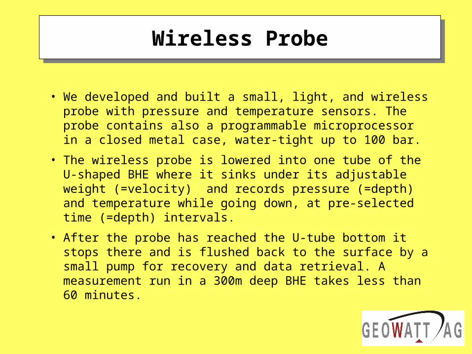
• We developed and built a small, light, and wireless probe with pressure and temperature sensors. The probe contains also a programmable microprocessor in a closed metal case, water-tight up to 100 bar.
• The wireless probe is lowered into one tube of the U-shaped BHE where it sinks under its adjustable weight (=velocity) and records pressure (=depth) and temperature while going down, at pre-selected time (=depth) intervals.
• After the probe has reached the U-tube bottom it stops there and is flushed back to the surface by a small pump for recovery and data retrieval. A measurement run in a 300m deep BHE takes less than 60 minutes.

Wireless Probe (“Fish”)Wireless Probe (“Fish”)
Electronics:
• P and
• T -Sensors
Probe case
235 x 23 mm
weight 99.8 g
Wireless Probe (“Fish”)Wireless Probe (“Fish”)
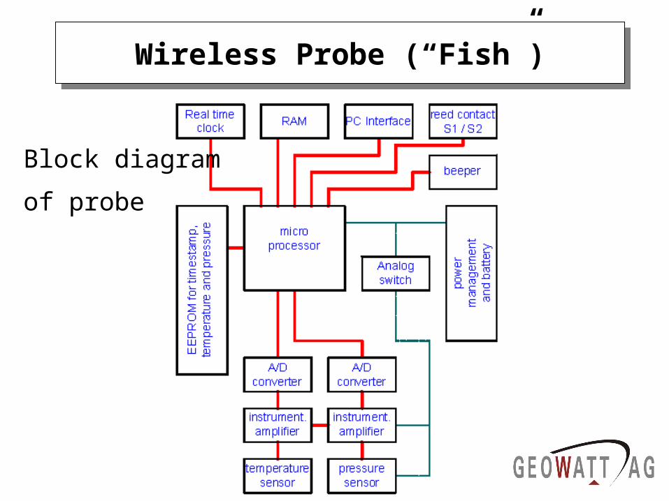
Block diagram
of probe

Wireless Probe (“Fish”)Wireless Probe (“Fish”)
The built-in electronics (ADC with 16bit resolution) consists of
• Analog/Digital Converter,
• microprocessor
• EEPROMs (=electric erasable/ programmable read-only memory) for data storage.
The software consists of three parts to perform the following tasks:
• controlling the probe operation
• communication probe laptop (for data retrieval)
• calibration.

Wireless Probe (“Fish”)Wireless Probe (“Fish”)
The controlling part runs in a programmable microprocessor (Basic Stamp BS2pe), performs the measurements and stores the data (time, pressure, temperature).
The communications part consists of a macro in an Excel Workbook, reads the data into an Excel table and enables the configuration of the wireless probe, to set the measurement mode as well as the setting of time, pressure and temperature intervals. Data deletion, synchronization of probe, and laptop timing are also accomplished.
Also the calibration part consists of a macro in an Excel Workbook; it enables to calibrate individual probes. The calibration parameters are stored in the probe. Thus the measurements can immediately be started, after configuration, with any of the probes built.

• Function checks, after testing for water-tightness, have been performed under laboratory conditions.
• The temperature calibration in a thermostat vessel, the pressure calibration by hydraulic means.
• The probe has high temperature resolution (± 0.003 C) and can store three times 16’000 measurements (time, pressure, temperature).
• The time constant of temperature measurement is 3.5 sec. Depth resolution is, due to the time constant, about ± 0.5 m.• The calibration functions for pressure and temperature are
described by second grade polynoms of the form y= a + bx + cx2. The calibrations constants a, b and c of each individual probe are stored in the probes.
Laboratory tests und calibrationLaboratory tests und calibration

Temperature calibration (range: 0 – 50 °C)
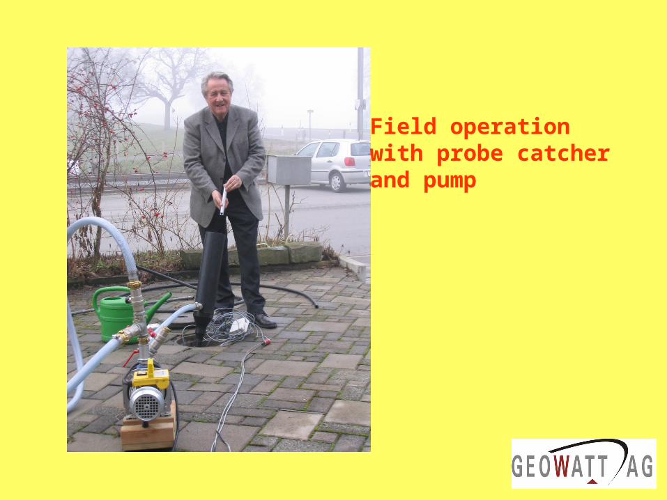
Field operationwith probe catcherand pump
20151050
50
100
150
200
250
300
OM
MU
SM
Qua
rt.
z 4
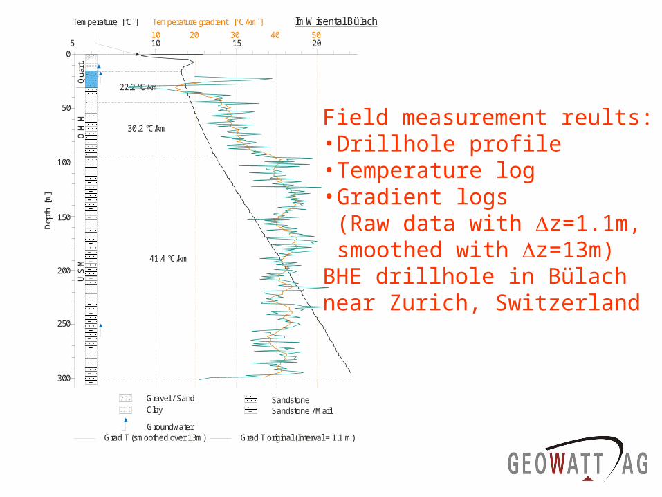
41.4 °C/km
30.2 °C/km
22.2 °C/km
Temperature [°C¨]
Dep
th [
m]
SandstoneSandstone / MarlClay
Gravel / Sand
10
50
100
150
200
250
300
2 3 4Thermal conductivity [W/mK]
Groundwater
Temperature gradient [°C/km¨]
10 20 30 40 50
ImWisental Bülach
Grad T (smoothed over 13m) Grad T original (Interval = 1.1 m)
Laboratory measurement with uncertainty(gray area)
Thermal conductivity derived from measured temperature gradient and local heat flow
Field measurement reults:• Drillhole profile• Temperature log• Gradient logs
(Raw data with z=1.1m,smoothed with z=13m)
BHE drillhole in Bülach near Zurich, Switzerland

Field measurementsField measurements
0
50
100
150
200
250
300
350
5 10 15 20 25
Andwil
Aeugst
Arbon
Arnegg R.
Arnegg S.
Gachnang
Bachenbülach
Bülach
Oberrieden
Reigoldswil
Zürich Dolder
Nango-Dori 01.09.04 125m
0
20
40
60
80
100
120
140
0 5 10 15 20 25
Nango-Dori01.09.04 125m
A00450SN Sapporo

Calculation of the thermal conductivity profile
• Assumption: pure conduction (disturbing effects like palaeclimate, groundwater flow to be corrected for beforehand)
• From the temperature log T(z) the gradient log T(z) is calculated depth sectionwise (i);
• Finally the thermal conductivity profile, with the local heat flow qloc from
T
q
i
loci

20151050
50
100
150
200
250
300
OM
MU
SM
Qua
rt.
z 4
41.4 °C/km
30.2 °C/km
22.2 °C/km
Temperature [°C¨]
Dep
th [
m]
SandstoneSandstone / MarlClay
Gravel / Sand
10
50
100
150
200
250
300
2 3 4Thermal conductivity [W/mK]
Groundwater
Temperature gradient [°C/km¨]
10 20 30 40 50
ImWisental Bülach
Grad T (smoothed over 13m) Grad T original (Interval = 1.1 m)
Laboratory measurement with uncertainty(gray area)
Thermal conductivity derived from measured temperature gradient and local heat flow
Calculated thermal conductivityprofile (full line),Laboratory measurements (vertical bars)BHE drillhole in Bülach/CH
m

Petrophysical data, samples from BHE drillhole in Bülach/CH
Probe Depth Lithology m
m
m
eff
eff
f
f
[W/m,K] [W/m,K] [g/cm3] [W/m,K] [W/m,K]IW-1 5 - 18 m Clay 1.69 0.05IW-2 18 - 28 m Gravel 3.55 0.18 2.69 0.20 0.05 2.50 0.11W-1 72 - 80 m Middle-/Coarse-sandstone 2.89 0.07 2.48 0.20 0.05 2.12 0.06W-2 104 - 106 m Marl 2.19 0.09 2.34 0.20 0.04 1.70 0.02IW-3 112 - 126 m Marl/Fine-sandstone 2.17 0.09 2.48 0.17 0.02 1.74 0.01W-3 148 - 152 m Fine-sandstone/Marl 2.37 0.20 2.59 0.15 0.01 1.95 0.03IW-4 150 - 160 m Fine-sandstone/Marl 2.64 0.07 2.53 0.12 0.02 2.23 0.02IW-5 210 - 226 m Fine-sandstone/Marl 2.69 0.20 2.57 0.13 0.01 2.22 0.03IW-6 228 - 248 m Middle-sandstone/Marl 2.62 0.14 2.57 0.13 0.01 2.17 0.02W-4 252 - 272 m Marl/Siltstone 2.20 0.07 2.55 0.16 0.01 1.79 0.01IW-7 278 - 298 m Marl 2.07 0.15 2.46 0.17 0.02 1.69 0.02 m: Thermal conductivity of rock matrix, m: Matrix density, eff: effective porosity, f: Thermal conductivity
of water-saturated sample, ±: measurement error
CONCLUSIONS
• Since probe manufacturing in 2003, several BHE boreholes have been logged in Switzerland. The results are fully satisfactory; the method is now routinely used to design large BHE arrays;
• The data processing yields the detailed distribution over the borehole profile;
• The wireless measurement offers several advantages: higher resolution, better signal/noise ratio than with logging cables;
• The measurement time for a 300m deep BHE is less than 60 minutes, whereas a Response Test takes at least 50 hours and requires large-scale equipment;
• The time saving is highly relevant under construction site conditions.

OUTLOOK
The probe can be used, besides for thermal conductivity determination:
• Lithologic subdivision of borehole profiles,
• Data acquisition for palaeoclimatic studies,
• Identification of groundwater flow.