A new arrangement of galvanic anodes for the repair of ... · The traditional 100 mV depolarisation...
21
•
Transcript of A new arrangement of galvanic anodes for the repair of ... · The traditional 100 mV depolarisation...

Loughborough UniversityInstitutional Repository
A new arrangement ofgalvanic anodes for the
repair of reinforced concretestructures
This item was submitted to Loughborough University's Institutional Repositoryby the/an author.
Citation: CHRISTODOULOU, C. ... et al, 2014. A new arrangement ofgalvanic anodes for the repair of reinforced concrete structures. Constructionand Building Materials, 50, pp. 300-307.
Additional Information:
• This is the author's version of a work that was accepted for publication inConstruction and Building Materials. Changes resulting from the publish-ing process, such as peer review, editing, corrections, structural format-ting, and other quality control mechanisms may not be reflected in thisdocument. Changes may have been made to this work since it was sub-mitted for publication. A definitive version was subsequently publishedat: http://dx.doi.org/10.1016/j.conbuildmat.2013.09.062
Metadata Record: https://dspace.lboro.ac.uk/2134/13593
Version: Accepted for publication
Publisher: c© Elsevier
Please cite the published version.

This item was submitted to Loughborough’s Institutional Repository (https://dspace.lboro.ac.uk/) by the author and is made available under the
following Creative Commons Licence conditions.
For the full text of this licence, please go to: http://creativecommons.org/licenses/by-nc-nd/2.5/

A new arrangement of galvanic anodes for the repair of reinforced
concrete structures
C Christodoulou1, C.I. Goodier2, S.A. Austin2, G.K. Glass3, J Webb1
1: AECOM Europe, Colmore Plaza, 20 Colmore Circus Queensway, Birmingham, B4 6AT,
U.K.
2: Loughborough University, School of Civil and Building Engineering, Loughborough, U.K.
3: Concrete Preservation Technologies, University of Nottingham Innovation Lab,
Nottingham, UK, NG7 2TU
e-mail to: [email protected]
ABSTRACT
Discrete galvanic anodes are traditionally embedded in the patch repairs of steel reinforced concrete (RC)
structures to offer corrosion prevention. This research investigated the performance of galvanic anodes
installed in the parent concrete surrounding the patch repair, in order to explore the performance of such a
new arrangement and identify its potential for wide-scale application.
This arrangement was tested on a RC multi-story car park and a RC bridge, with both suffering from chloride-
induced corrosion of the reinforcement. The performance of the anodes was assessed using close-interval
potential mapping for 215 days after installation. The results indicate that the anodes polarised the steel at a
significant distance away from the patch repair interface, up to 600 mm in some cases. It illustrates that such
an arrangement may be advantageous when repairing RC structures as the corrosion prevention can be
targeted at the steel in the surrounding parent concrete, which is traditionally considered to be at higher risk
due to incipient anode development.
Keywords
Reinforced concrete; corrosion; galvanic anodes; potential mapping
INTRODUCTION
Patch repairs of deteriorating concrete is a common approach to rehabilitate defective concrete structures.
Bridge Advice Note 35 [1] suggests that areas which show chloride concentrations greater than 0.3% by
weight of cement and half-cell potential measurements higher than -350mV should be removed. Concrete
replacement to this extent on chloride-contaminated structures can be very onerous and expensive [2].
Galvanic anodes have been used to limit the extent of concrete replacement and extend the service life of
patch repairs to RC structures [3 – 5]. They respond to changes in the environmental conditions they are
exposed to [3, 6, 7]. Such an effect will be more dominant in parent concrete that has a residual level of

chloride contamination as opposed to the non-contaminated repair concrete or mortar and this has been
employed to extend the use of galvanic anodes [8, 9].
This work measured the performance of galvanic anodes installed within the parent concrete around the
perimeter of the repair as opposed to the traditional approach of placing the anodes within the patch repair
area itself. The anodes were monitored in order to assess their performance and the results provide an
improved understanding of the corrosion protection mechanism [5].
THEORETICAL BACKGROUND
Galvanic anodes operate on the principle of differential potentials of metals [3, 4]. A schematic illustration of a
galvanic cathodic protection (CP) system is provided in Figure 1. For the protection of steel reinforcement in
concrete, such electrochemically more active metals include zinc, aluminium and magnesium.
Figure 1: A compact discrete galvanic anode connected to the steel reinforcement which becomes the
cathode of the galvanic cell that is formed [10].
Contemporary galvanic anode systems can be categorised as (Figure 2) [10]:
i. Metal coatings applied directly to the concrete surface
ii. Sheet anodes attached to the concrete surface
iii. Distributed anodes embedded in a cementitious overlay
iv. Discrete anodes embedded in cavities in the concrete

Figure 2: Galvanic anode examples (i) a thermally applied metal coating (top left), (ii) adhesive zinc sheets
(top right) [4], discrete anodes in drilled holes (bottom left) [15], discrete anodes installed in patch repair
(bottom right).
For galvanic anode systems, current output tends to fall with time as the anode is consumed. As a result
galvanic protection is not generally achieved by sustaining an adequate level of steel polarisation, as is the
case for other electrochemical treatments [9, 11].
For this reason, traditional galvanic anode systems are only installed as a corrosion prevention system and
take the form of discrete anodes embedded within concrete patch repairs [3, 12]. The concrete repair process
will restore steel passivity [4, 13]. Thus, embedded galvanic anodes are only required to provide a small
cathodic polarisation to the steel reinforcement in the parent concrete adjacent to the repair area, which is
considered to be an area of high risk [14 – 16]. This is also commonly known as “cathodic prevention” [17].
The traditional 100 mV depolarisation performance criterion for Impressed Current Cathodic Protection (ICCP)
systems has also been routinely applied to galvanic anode systems [18, 19]. However, several publications
note that this is not suitable for galvanic CP systems which are primarily designed to offer cathodic prevention
only [9, 19 – 21]. The new International standard for CP of steel in concrete [17] has taken this into account
and performance assessment of galvanic CP is preferably focused on corrosion risk assessment. In practice
this is based on monitoring of changes in the condition of the reinforcement that arise as the result of the
protective effects afforded by galvanic CP [11]. Examples include corrosion potential as a function of time
and/or distance from an anode or edge of the repaired area and/or corrosion rate [5, 22].
There are a number of factors affecting the performance of galvanic anode systems. These are summarised
in Table 1.

Factor Effect
Concrete Resistivity An increase in concrete resistivity reduces the protection current output of a
galvanic anode which limits the protection delivered [3, 4, 17].
Current distribution Discrete anodes distribute current poorly compared to surface applied anodes
but protection can be targeted to the area of need [3, 4, 17].
Continuing corrosion Products designed for use in a preventative role may fail when trying to arrest
an active corrosion process [23].
Charge capacity /
current output
The maximum theoretical life cannot exceed a period determined by the anode
charge capacity and anode current output.
Anode activity /
surface area
Determines protection current output and discrete anodes in particular need a
method of anode activation. For alkali activated systems, anode activation is
dependent on the quantity of alkali in the assembly.
Anode delamination /
adhesion to concrete
Galvanic anode systems applied to concrete surfaces in particular are at risk of
suffering from delamination and loss of contact with the concrete.
Table 1: Factors affecting the performance of galvanic anode systems applied to RC structures [10].
METHODOLOGY
This section describes the structures and the testing regime employed to evaluate the performance of the
galvanic anodes.
Structures
The structures comprised a multi-storey car park (MSCP) with 11 stories in the East Midlands, UK and an 18
span bridge approximately 180 m long in Northern Scotland, UK. This MSCP was built in the early 1970s and
it has a concrete one-way spanning ribbed type deck arrangement with 80 mm thick slab in-between the ribs
(Figure 3). Due to the nature of the structure it was lightly reinforced with steel mesh. The bridge was also
built in the early 1970s and comprised prestressed concrete beams supported on RC crossbeams with steel
rendhex pile supports (Figure 4). Due to the nature of dealing with full-scale structures at an age of at least 40
years, full details of the concrete composition were not available.
Figure 3: MSCP structural arrangement

Figure 4: Bridge structural arrangement
Both structures suffered from chloride-induced corrosion [5] (Figure 5). The MSCP exhibited structural
damage on the decks and soffits with exposed reinforcement and extensive concrete spalling. Chloride
analysis, at more than 50 test locations on the concrete slabs and soffits of various floors, conducted in
accordance with BSI [24], indicated that the chloride levels were up to 2.92% by weight of cement at a depth
of 30 mm to 55 mm. This is high and presents a corrosion risk that should be addressed [1].
Figure 5: Chloride-induced corrosion and spalling to the MSCP and bridge structures (respectively)
The bridge also exhibited widespread areas of chloride-induced deterioration, being located in an aggressive
marine environment. Chloride analysis testing at 12 locations on the RC crossbeams, in accordance with BSI
[24], indicated high concentration levels of around 1.8% by weight of cement at a depth of 25 to 50mm - the
depth at which the reinforcement is located. This is high and presents a corrosion risk that should be
addressed [1].
Design Arrangement
The design for the structural repairs involved removing only physically deteriorated concrete by jack hammer
on the MSCP and hydro-demolition on the bridge. The breakouts extended beyond the back of the
reinforcement and at a minimum additional depth equal to the aggregate size of the repair mortar plus 3 mm.
The steel was cleaned by means of rotary steel wire brushes [13].

The nature of commercial contracts and their risk allocation require that a contractor uses specialist repair
materials conforming to a standard. Two proprietary repair materials, labelled A and B, certified as class
structural repair mortars in accordance with BS EN 1504-3 [12, 25] were applied to restore the concrete
profile. Because of the nature of this study it is not possible to give an equivalent material detail to that
provided in laboratory experiments, although further details may be found elsewhere [13]. Table 2 provides
further material details, how and where each one was applied.
Material Structure
type
Repair
location
Properties Application method
A MSCP Deck
Portland cement based, flowable, polymer modified,
shrinkage compensated micro-concrete. Twenty five
kilograms of material was mixed with 2.50 litres of water.
Poured and trowel
finished
B MSCP –
Bridge
Soffits and
vertical faces
Portland cement based, polymer modified, shrinkage
compensated repair mortar containing silica fume. Water to
cement ratio ranges 0.35 - 0.4.
Dry spray or hand
applied and trowel
finished
Table 2: Repair materials and location
Galvanic anodes with a diameter of 20 mm and a length of 40 mm, each containing approximately 65 grams
of zinc, were installed in pre-drilled holes of 25 mm diameter and 45 mm long in the parent concrete, as close
as practically possible to the edge of the patch and then filled with proprietary backfill (Figure 6). A titanium
wire integrated with the galvanic anodes made a connection to the steel reinforcement within the repair area.
On the MSCP, the design galvanic anode spacing was 300 mm centres, and on the bridge structures 250 mm
centres.

Figure 6: Galvanic anode installation procedure, (a) repair area following breakout and with location of anode
installation marked out, (b) testing for reinforcement continuity, (c) pre-drilled holes for anode installation, (d)
installation of galvanic anode and (e) connection of galvanic anode to the steel reinforcement and anode hole
following filling with the proprietary backfill.
Testing Regime
Measuring steel potentials against the potential of a standard reference electrode (i.e. absolute potentials) is a
well established non-destructive monitoring technique [26 – 29]. An alternative to this, are electrode to
electrode potentials (i.e. relative potentials) which provide information on the electric field in concrete and as
such locating areas of actively corroding steel by considering spatial variation of potentials [27, 31]. While the
use of relative potential differences in reinforced concrete galvanic CP is recent, such analysis has been used
for sometime in pipeline CP [28, 30].
Potential maps were obtained on a 50 mm square grid using a portable Ag/AgCl/0.5M KCl reference electrode
and a high impedance multi-meter. The size of each grid varied in accordance to the size of the repair but in
general it extended up to 700 mm in the parent concrete when measured from the edge of the repair. All the
potential values herein are reported relative to the most positive value obtained at the time of the
measurement.
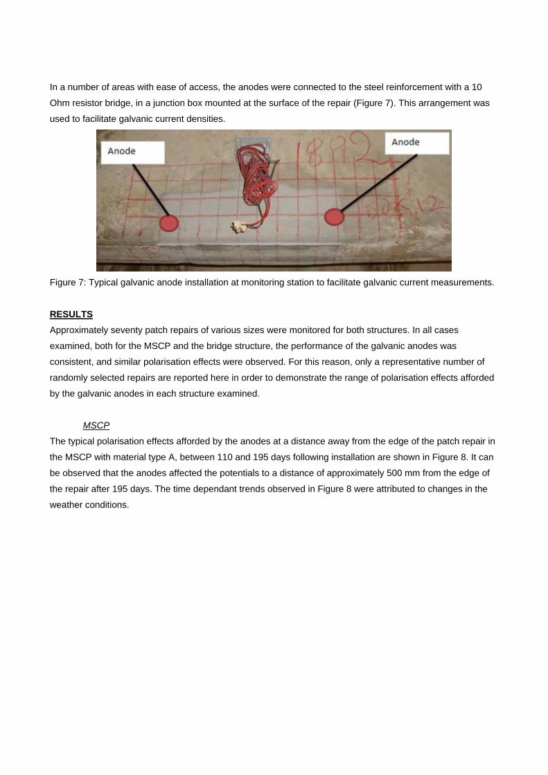
In a number of areas with ease of access, the anodes were connected to the steel reinforcement with a 10
Ohm resistor bridge, in a junction box mounted at the surface of the repair (Figure 7). This arrangement was
used to facilitate galvanic current densities.
Figure 7: Typical galvanic anode installation at monitoring station to facilitate galvanic current measurements.
RESULTS
Approximately seventy patch repairs of various sizes were monitored for both structures. In all cases
examined, both for the MSCP and the bridge structure, the performance of the galvanic anodes was
consistent, and similar polarisation effects were observed. For this reason, only a representative number of
randomly selected repairs are reported here in order to demonstrate the range of polarisation effects afforded
by the galvanic anodes in each structure examined.
MSCP
The typical polarisation effects afforded by the anodes at a distance away from the edge of the patch repair in
the MSCP with material type A, between 110 and 195 days following installation are shown in Figure 8. It can
be observed that the anodes affected the potentials to a distance of approximately 500 mm from the edge of
the repair after 195 days. The time dependant trends observed in Figure 8 were attributed to changes in the
weather conditions.
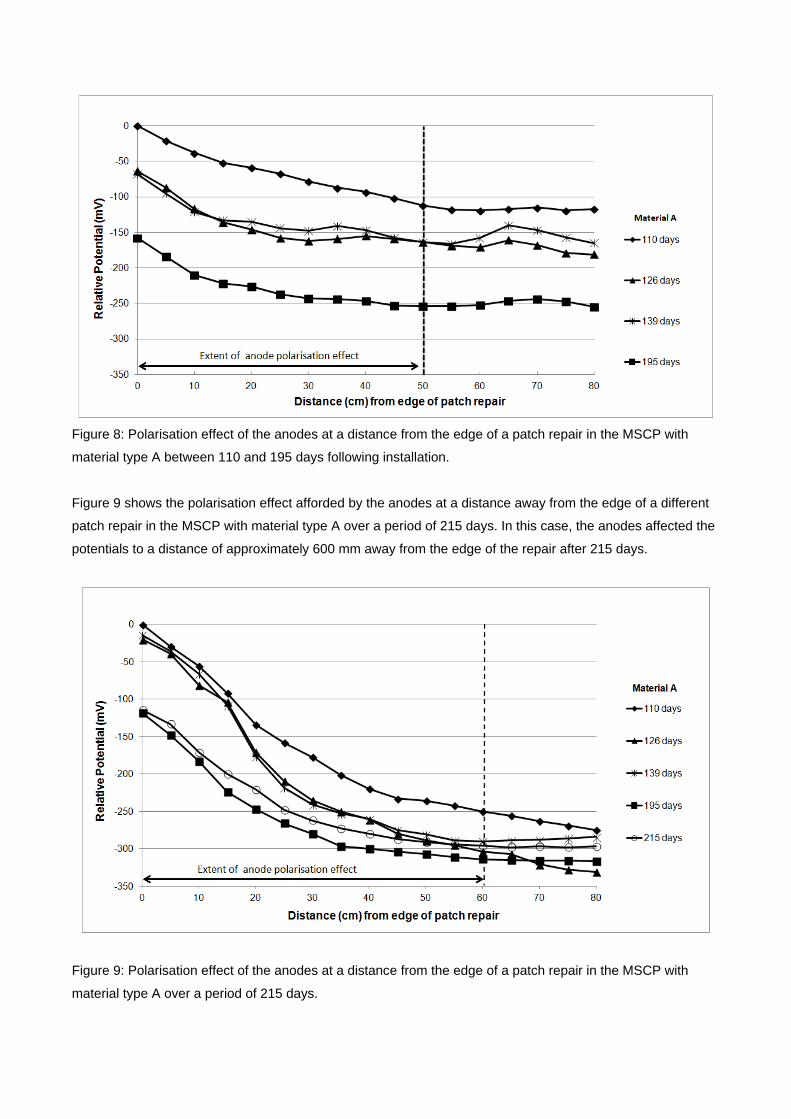
Figure 8: Polarisation effect of the anodes at a distance from the edge of a patch repair in the MSCP with
material type A between 110 and 195 days following installation.
Figure 9 shows the polarisation effect afforded by the anodes at a distance away from the edge of a different
patch repair in the MSCP with material type A over a period of 215 days. In this case, the anodes affected the
potentials to a distance of approximately 600 mm away from the edge of the repair after 215 days.
Figure 9: Polarisation effect of the anodes at a distance from the edge of a patch repair in the MSCP with
material type A over a period of 215 days.

A typical repair together with a schematic illustration of the location of the galvanic anodes is shown in Figure
10. The potential mapping around this particular repair over a period of 195 days is demonstrated in Figure
11. It can be observed that the anodic points identified in the mapping, coincided at all times with the location
of the galvanic anodes (anodic points have been circled over). It can be observed that the potentials never
rose higher than the imaginary lines connecting the anodic spots, suggesting that there are no other anodic
spots between the galvanic anodes.
Figure 10: Typical concrete repair (left) and schematic illustration of the location of the galvanic anodes (right).

Figure 11: Potential mapping around a repair location with Material A up to 195 days following installation of
the galvanic anodes.
Contour plots showing potential mapping results both before and after repairing an area of corrosion damage
with material A are shown in Figure 12. The repair material had cured for 30 days when the data for the post
repair contour plot was recorded. It is evident that before the repair (Figure 12 (a)), the potential in the area of
the corroding steel was about 100 mV more negative than the potential in the adjacent parent concrete. 30
days after the repair this difference increased to approximately 200 mV.

Figure 12: Surface potential mapping on car park repair with Material A (a) before and (b) 30 days after repair
[13]. Dashed line in (b) illustrates extent of patch repair.
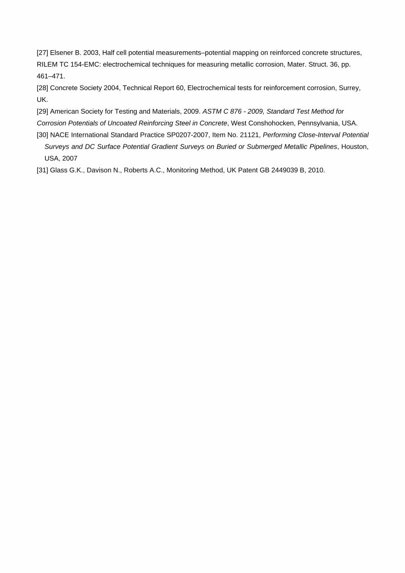
Contour plots of potential mapping following concrete replacement before and after connection of the galvanic
anodes are provided in Figure 13. The application of a cementitious repair mortar initially depressed steel
potentials within the patch repair to more negative values than the parent concrete (Figure 13 (a)). After the
anodes were connected to the reinforcement, it can be observed that the polarisation effects afforded
extended at least 250mm to the steel in the parent concrete (Figure 13 (b)) and further depressed steel
potentials by close to 100 mV. The galvanic current output varied from 1.5 mA/m2 to 1.0 mA/m2 of steel
surface area, demonstrating a responsive behaviour with time.
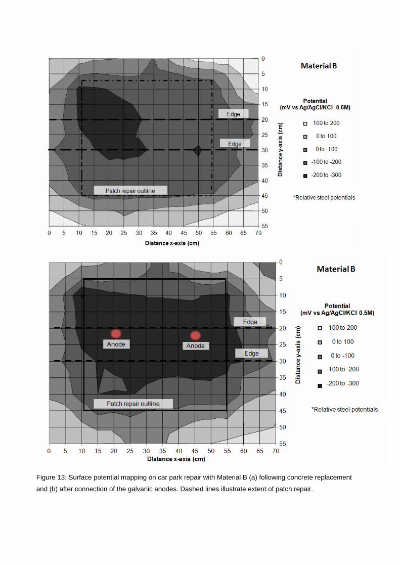
Figure 13: Surface potential mapping on car park repair with Material B (a) following concrete replacement
and (b) after connection of the galvanic anodes. Dashed lines illustrate extent of patch repair.

Bridge
Typical polarisation effects afforded by the anodes at a distance away from the edge of the patch repair from
the bridge structure with material type B, between 110 and 195 days following installation are shown in Figure
14. The anodes affected the potentials to a distance of at least 400 mm away from the edge of the repair at 30
days after their installation.
Figure 14: Polarisation effect of anodes at a distance from the edge of a patch repair from the bridge
structure, with material type B, 30 days following installation.
Figure 15 shows the polarisation effect afforded by the anodes at a different repair, with material B, from the
bridge structure 45 days following their installation. It can be observed that the anodes affected the steel
potentials again to a distance of at least 400mm away from the edge of the repair.

Figure 15: Polarisation effect of anodes at a distance from the edge of a patch repair from the bridge
structure, with material type B, 45 days following installation.
From the above figures it can also be observed that the potentials of the steel in the parent concrete did not
always reach a plateau, which suggested that the anodes may still be effective at greater distances. Access
restraints generally restricted potential mapping on the bridge structure being generally restricted to a distance
of 500 mm in length.
The above, are typical and re-occurring findings on the polarisation effect afforded by the anodes to steel in
parent concrete at a distance from the edge of a patch repair both for material type A and B on both
structures. The exact polarisation distance varied between 250 mm and 600 mm depending on the age of the
anodes, the prevailing environmental conditions at the time of testing and steel density. For the MSCP,
readings could not be obtained for longer than 215 days as thereafter the slabs received a surface applied
waterproofing and no longer than45 days for the bridge structure due to access restrictions.
DISCUSSION
This study investigated the performance of galvanic anodes installed in parent concrete on two major RC
structures in the UK. Monitoring was performed by close-interval relative potential mapping around the
perimeter of the repairs to verify that the anodes were still active, and at staged distances away from the
repairs to assess the polarisation effect afforded by the anodes to the steel in the parent concrete.
The performance monitoring data indicates that the galvanic anodes affected steel potentials in parent
concrete as a distance away from the edge of the patch. For the MSCP, with steel mesh reinforcement only,
the polarisation effect was to a distance of approximately 600 mm away from the edge of the patch. For the
bridge structure, which inherently had a higher amount of reinforcing steel, the polarisation effect afforded was

reduced to approximately 400 mm from the edge of the patch. This indicates that galvanic anodes have
limitations and their beneficial effects are reduced with an increasing density of reinforcement.
Repair materials that conform to standards for structural repairs such as BS EN 1504 [29] did not affect the
performance of galvanic anodes installed in parent concrete around the edge of the repair, although they are
not generally considered suitable for use together with galvanic anodes due to their high resistivity [17]. By
contrast, such materials will improve the quality and longevity of the repair itself, and due to their higher
resistivity will preferentially direct current from the galvanic anodes to steel in the parent concrete, which is
considered to be at higher risk.
Traditionally, half-cell potential mapping in the UK is undertaken based on a 500 mm grid and for rapid
corrosion assessment spacing up to 1.2 m is occasionally employed [29]. Undertaking relative potential
mapping at a small grid (50 mm), as in the case of the present study, has the advantage of collecting time-
dependent spatial variation information about the condition of the reinforcement which is particularly suited to
galvanic systems which are often installed without any monitoring facility (including a connection to the steel
reinforcement).
A new criterion, to that of 100 mV depolarisation, may be adopted for assessing the performance of galvanic
anode systems by means potential mapping to obtain spatial variations. Potential mapping around the
perimeter of a patch repair with galvanic anodes installed in the parent concrete, should demonstrate that the
anodes afford a dominant (i.e. be dominant over any effect of a steel anode) influence on the steel potentials
away from the area of patch repair that is at least equal to half the spacing between anodes. This alternative
performance criterion is also in line with the work of Holmes et al. [8].
CONCLUSIONS
The results of this work lead to the following conclusions:
1. Galvanic anodes installed in pre-drilled cavities formed in the parent concrete exposed within an area of
patch repair can provide substantial protection to the steel reinforcement in the parent concrete outside
the repair. The anodes had a dominant effect on potentials within the concrete to a distance of between
250 mm and 600 mm from the edge of the patch repair. An important factor affecting the extent of the
protective effect is the steel density (quantity).
2. A repair material that conforms to standards for structural repairs such as BS EN 1504 [29] will not affect
the performance of galvanic anodes installed in parent concrete around the edge of the repair. By
contrast, it will improve the quality and longevity of the repair itself and will preferentially direct current
from the galvanic anodes to steel in the parent concrete, which is considered to be at higher risk.
3. Close-interval potential mapping (50mm spacing) is an effective technique to assess the performance of
galvanic anodes. It has the additional advantage that localised active corrosion spots can also be
detected if present.

4. An alternative criterion, to that of 100 mV depolarisation, is proposed for assessing the performance of
galvanic anodes: the anodes should afford a dominant (i.e. be dominant over any effect of a steel anode)
influence on the steel potentials away from the area of patch repair that is at least equal to half the
spacing between anodes.
ACKNOWLEDGEMENTS
The authors would like to thank AECOM and the EPSRC (through the Centre for Innovative and Collaborative
Engineering (CICE) at Loughborough University, grant no. EP/G037272/1) for their commercial and financial
support.
REFERENCES
[1] Design Manual for Road and Bridges, Volume 3, Section 3, Part BA 35/1990 Inspection and Repair of
Concrete Highway Structures, Departmental Standard, UK.
[2] Christodoulou C., Electrochemical treatments of corroded reinforcement in concrete. IN: Alexander, M. et
al. (eds.)Concrete Repair, Rehabilitation and Retrofitting II - Proceedings of the 2nd International
Conference on Concrete Repair, Rehabilitation and Retrofitting, ICCRRR-2, 24-26 November 2008, Cape
Town, South Africa, pp. 297 – 298, ISBN 978-0-415-46850-3
[3] NACE International Publication 01105, Item No. 24224, Sacrificial Cathodic protection of Reinforced
Concrete Elements — A State-of-the-Art Report, Houston, USA, March 2005
[4] Concrete Society 2011, Technical Report 73, Cathodic Protection of Steel in Concrete, Surrey, UK.
[5] Christodoulou C., Glass G., Webb J., Austin S.A. Goodier C.I., A new approach for the patch repair of car
parks using galvanic anodes, Concrete Solutions 2011, : Grantham, M., Mechtcherine, V. and Schneck, U.
(eds). Concrete Solutions 2011: Proceedings of the International Conference on Concrete Solutions 2011.
London: CRC Press, ISBN 978-0-203-13468-9.
[6] John G., Cottis B., Laboratory Testing and Computer Modelling of the Performance of Sacrificial Anodes
for use in Reinforced Concrete Structures, Paper number 03302, Corrosion 2003, NACE International,
Houston, USA.
[7] Christodoulou, C., Glass, G., Webb, J. 2009. Corrosion management of concrete structures, The Structural
Engineer, Volume 87, 23/24, December 2009.
[8] Holmes S.P., Wilcox G.D., Robins P.J., Glass G.K., Roberts A.C., Responsive behaviour of galvanic
anodes in concrete and the basis for its utilisation, Corrosion Science, 53, pp. 3450 – 3454.
[9] Glass G., Christodoulou C., Holmes S.P., 2012, Protection of steel in concrete using galvanic and hybrid
electrochemical treatments, IN: Alexander, M.G. et al. (eds.), Concrete Repair, Rehabilitation and Retrofitting
III - Proceedings of the 3rd International Conference on Concrete Repair, Rehabilitation and Retrofitting,
ICCRRR 2012, pp. 523 – 526, ISBN 978-0-415-89952-9.
[10] Christodoulou C., Glass G., Webb J., Ngala V., Beamish S., Gilbert P., Evaluation of galvanic
technologies available for bridge structures. Presented at: Structural Faults and Repair, 12th International
Conference, Edinburgh, UK, 10 -12 June 2008, 11pp, ISBN 0-947644-62-7.

[11] Glass G., Christodoulou C., Towards rendering steel reinforced concrete immune to corrosion,
Australasian Corrosion Association 2012 Annual Meeting, 11-14 November 2012, Melbourne, Australia, 2012,
paper 159, 11p.
[12] Concrete Society, Repair of concrete structures with reference to BS EN 1504, Technical Report 69,
Surrey, UK, 2009.
[13] Christodoulou C., Goodier C.I., Austin S.A, Webb J., Glass G., Diagnosing the cause of incipient anodes
in repaired reinforced concrete structures, Corrosion Science, 69 (2013), pp. 123 – 129 DOI information:
10.1016/j.corsci.2012.11.032
[14] Christodoulou C., Glass G., Webb J., Austin S., Goodier C., Assessing the long term benefits of
Impressed Current Cathodic Protection, Corrosion Science, 52 (2010), pp. 2671 – 2679 DOI information:
10.1016/j.corsci.2010.04.018
[15] Glass, G.K., Roberts, A.C., Davison, N., Hybrid corrosion protection for chloride contaminated concrete,
Proceedings of the Institute of Civil Engineers, Construction Materials, 161 (2008) pp. 163 – 172.
[16] Glass G.K., Reddy B., Clark L.A. 2007, Making reinforced concrete immune from chloride corrosion,
Construction Materials, 160, pp. 155 – 164.
[17] British Standards Institution, 2012. BS EN ISO 12696:2012, Cathodic protection of steel in concrete,
London: BSI.
[18] Bennett J., Talbot C., Extending the life of concrete patch repair with chemically enhanced zinc anodes,
Paper number 02255, Corrosion 2002, NACE International, Houston, USA.
[19] Dugarte M., Sagüés A.A., Galvanic point anodes for extending the service life of patched areas upon
reinforced concrete bridge members, Contract No. BD544-09, Final Report to Florida Department of
Transportation, Tampa, Florida, USA, September 2009.
[20] Bertolini L., Bolzoni F., Cigada A., Pastore T., Pedeferri P. 1993, Cathodic protection of new and old
reinforced concrete structures, Corrosion Science 35, pp. 1633 – 1639.
[21] Pedeferri P. 1996, Cathodic protection and cathodic prevention, Construction and Building Materials, 10,
pp 391 – 402.
[22] Dugarte M., Sagüés A.A., Powers R.G., Lasa I.R. 2007, Evaluation of point anodes for corrosion
prevention in reinforced concrete, Corrosion 2007, Paper No.07304 NACE International, Houston, USA.
[23] Brown M. C., Sharp S. R. 2008. "Survey of Cathodic Protection Systems on Virginia Bridges" Report
VTRC 07-R35, Virginia Transportation Research Council
(www.virginiadot.org/vtrc/main/online_reports/pdf/07-r35.pdf).
[24] British Standards Institution, BS 1881–124:1988 Testing concrete, Methods for analysis of hardened
concrete, London, BSI, 1988.
[25] British Standards Institution, BS EN 1504:2005 Products and Systems for the Protection and Repair of
Concrete Structures – Definitions, Requirements, Quality Control and Evaluation of Conformity – Part 3:
Structural and Non Structural Repair, BSI, London, 2005.
[26] Elsener B. 2001. Half-cell potential mapping to assess repair work on RC structures, Construction and
Building Materials, 15, 133 – 139.
[27] Elsener B. 2003, Half cell potential measurements–potential mapping on reinforced concrete structures,
RILEM TC 154-EMC: electrochemical techniques for measuring metallic corrosion, Mater. Struct. 36, pp.
461–471.
[28] Concrete Society 2004, Technical Report 60, Electrochemical tests for reinforcement corrosion, Surrey,
UK.
[29] American Society for Testing and Materials, 2009. ASTM C 876 - 2009, Standard Test Method for
Corrosion Potentials of Uncoated Reinforcing Steel in Concrete, West Conshohocken, Pennsylvania, USA.
[30] NACE International Standard Practice SP0207-2007, Item No. 21121, Performing Close-Interval Potential
Surveys and DC Surface Potential Gradient Surveys on Buried or Submerged Metallic Pipelines, Houston,
USA, 2007
[31] Glass G.K., Davison N., Roberts A.C., Monitoring Method, UK Patent GB 2449039 B, 2010.