
ERDC/CERL TR-07-26, Cathodic Protection of Hot Water Tanks · 2011-05-14 · the use of ceramic...
151
ERDC/CERL TR-07-26 DoD Corrosion Prevention and Control Program Cathodic Protection of Hot Water Tanks at Fort Sill Final Report on Project AR-F-322 for FY05 L.D. Stephenson, Ashok Kumar, and James Bushman June 2007 Construction Engineering Research Laboratory Approved for public release; distribution is unlimited.
Transcript of ERDC/CERL TR-07-26, Cathodic Protection of Hot Water Tanks · 2011-05-14 · the use of ceramic...

ERD
C/CE
RL
TR-0
7-2
6
DoD Corrosion Prevention and Control Program
Cathodic Protection of Hot Water Tanks at Fort Sill Final Report on Project AR-F-322 for FY05
L.D. Stephenson, Ashok Kumar, and James Bushman June 2007
Con
stru
ctio
n E
ngi
nee
rin
g R
esea
rch
Lab
orat
ory
Approved for public release; distribution is unlimited.


DoD Corrosion Prevention and Control Program
ERDC/CERL TR-07-26 June 2007
Cathodic Protection of Hot Water Tanks at Fort Sill Final Report on Project AR-F-322 for FY05
L.D. Stephenson and Ashok Kumar
Construction Engineering Research Laboratory U.S. Army Engineer Research and Development Center 2902 Newmark Drive Champaign, IL 61822
James Bushman
Bushman & Associates, Inc. PO Box 425 Medina, OH 44258
Final report
Approved for public release; distribution is unlimited.
Prepared for Office of the Secretary of Defense (OUSD(AT&L)) 3090 Defense Pentagon Washington, DC 20301-3090
Under Military Interdepartmental Purchase Request MIPR5CCERB1011 and MIPR5CROBB1012

ERDC/CERL TR-07-26 ii
Abstract: This corrosion prevention and control project demonstrated the use of ceramic anodes for impressed current cathodic protection (ICCP) systems for retrofitting in six large 1,000 to 3,500 gallon hot water storage tanks that service barracks and adjoining mess halls at Fort Sill, OK. The cathodic protection systems were designed to provide corrosion protection to the bare steel interior of the tanks that are susceptible to cor-rosion. This is a first time installation of horizontal anode in large hot wa-ter storage tank ASME Pressure Vessel with no man-ways. These cathodic protection systems have continued to operate as designed since their ini-tial operation in April 2006 and have provided complete corrosion control since their original installation. The lifetimes of these large tanks are ex-pected to be extended by 30 years as a result of installing the impressed current cathodic protection systems using ceramic coated (mixed metal oxide) anodes. In addition, 17 smaller hot water tanks and hot water heat-ers (37 to 1,000 gal) were replaced with new hot water tanks and hot water heaters with factory-installed sacrificial anodes and glass linings. For the smaller tanks, it is more economical to use glass linings and sacrificial an-odes than ICCP systems.
DISCLAIMER: The contents of this report are not to be used for advertising, publication, or promotional purposes. Citation of trade names does not constitute an official endorsement or approval of the use of such commercial products. All product names and trademarks cited are the property of their respective owners. The findings of this report are not to be construed as an official Department of the Army position unless so designated by other authorized documents. DESTROY THIS REPORT WHEN NO LONGER NEEDED. DO NOT RETURN IT TO THE ORIGINATOR.
DISCLAIMER: The contents of this report are not to be used for advertising, publication, or promotional purposes. Citation of trade names does not constitute an official endorsement or approval of the use of such commercial products. All product names and trademarks cited are the property of their respective owners. The findings of this report are not to be construed as an official Department of the Army position unless so designated by other authorized documents. DESTROY THIS REPORT WHEN NO LONGER NEEDED. DO NOT RETURN IT TO THE ORIGINATOR.

ERDC/CERL TR-07-26 iii
Contents Figures and Tables.................................................................................................................................iv
Introduction ............................................................................................................................................vi
Executive Summary ..............................................................................................................................vii
Unit Conversion Factors......................................................................................................................viii
1 Background..................................................................................................................................... 1
2 Lessons Learned............................................................................................................................. 2
3 Technical Investigation.................................................................................................................. 3 Problem..................................................................................................................................... 3 Objectives ................................................................................................................................. 3 Approach................................................................................................................................... 3 Results ...................................................................................................................................... 4 Initial testing, adjusting, and monitoring results ..................................................................19 Installation of new replacement water heaters and tanks ..................................................23
4 Metrics...........................................................................................................................................25
5 Economic Summary .....................................................................................................................26 Base contract costs................................................................................................................26 ROI analysis ............................................................................................................................26
6 Recommendations.......................................................................................................................27
7 Implementation ............................................................................................................................28
8 Conclusions...................................................................................................................................29
Appendix A: Contractor’s Safety Manual and Communications Plan ...........................................A1
Appendix B: Rectifier Manual and Electric Schematic ...................................................................B1
Appendix C: ICCP System Replacement Parts List .........................................................................C1
Appendix D: Recommended Future Monitoring Data Sheets ........................................................D1
Appendix E: Repair Visit Report .........................................................................................................E1
Appendix F: ROI Assumptions, Calculations, and Validation..........................................................F1
Report Documentation Page

ERDC/CERL TR-07-26 iv
Figures and Tables
Figures
Figure 1. Schematic of ICCP system for hot water storage tanks at Fort Sill. ...................................... 8 Figure 2. Schematic of ICCP system for hot water storage tanks at Fort Sill showing detail of anode installation and electrical connections. ................................................................................... 9 Figure 3. AC to DC Constant Voltage Rectifier/Controller Unit with Power Rheo monitor system operates red/yellow alarm light and uptime hour meter – identical unit used for all six systems................................................................................................................................................ 11 Figure 4. Reference Electrode Potential Monitoring Port with cap in place. ......................................12 Figure 5. Precious metal oxide (ceramic) coated titanium rod entrance condulet with screw-off cover plate. ...............................................................................................................................12 Figure 6. Typical floor rack-mounted ICCP rectifier. Note green light is on indicating unit is operating within design current limits....................................................................................................13 Figure 7. Anode (¼-in. diameter) rod extending out of hot water storage tank with black insulation positive lead wire from ICCP rectifier unit attached. (Note white insulation wire is rectifier system negative ground wire). ..............................................................................................13 Figure 8. AC fuse on secondary side of Variac power transformer...................................................... 14 Figure 9. Input circuit breaker; use this breaker to interrupt system output when performing cathodic protection IR Drop Free potential measurements on hot water tank. .............14 Figure 10. Digital “up-time” meter records accumulated hours system operating with green-light on (system current within minimum/maximum limits set by corrosion engineer at time of last system annual performance tests). ...............................................................................15 Figure 11. Positive and negative terminals for measuring system DC voltage output– note positive (+) anode terminal is on right and system negative (-) terminal is on left. ...........................15 Figure 12. Outer cap on port must first be removed with pliers or wrench........................................ 16 Figure 13. Once cap is removed, inner plug on access port must be removed using hex key stored inside rectifier manual plastic jacket................................................................................... 16 Figure 14. To facilitate contracting the osmotic conductor side of the port, cotton or paper “wadding” is moistened and pushed down inside the port to the tip of a standard reference electrode placed in contact with the remaining portion of the wadding sticking out of the port........................................................................................................................................... 17 Figure 15. After carefully wiping dry the exterior of the port a calibrated Cu-CuSO4 electrode is placed in contact with the moist wadding......................................................................... 17 Figure 16. The DC voltmeter positive lead is connected to the reference electrode and the negative is connected to the structure...................................................................................................18 Figure 17. Current output alarm circuit control and adjustment panel...............................................18 Figure 18. Note green light is lit indicating that system DC current output is within the range set at the last detailed annual corrosion / cathodic protection system effectiveness check-out of the system...........................................................................................................................19 Figure 19. Typical 37 gallon replacement tank with glass linings and sacrificial anodes installed at Fort Sill................................................................................................................................... 24

ERDC/CERL TR-07-26 v
Tables
Table 1. Fort Sill Starship barracks hot water storage tank dimensions. ............................................. 4 Table 2. ICCP control parameters for hot water storage tanks at Fort Sill. ........................................... 5 Table 3. Bare steel ICCP anode resistance and current parameters for hot water storage tanks at Fort Sill.......................................................................................................................................... 6 Table 4. ICCP current output with control parameters and anode life for hot water storage tanks at Fort Sill.......................................................................................................................................... 7 Table 5. Fort Sill hot water storage tank ICCP system final checkout. ................................................ 21 Table 6. Data from hot water tank with defective Teflon sleeve BEFORE repairs on 22 July 2006..........................................................................................................................................................22 Table 7. Data from hot water tank with defective Teflon sleeve AFTER repairs on 22 July 2006..........................................................................................................................................................22 Table 8. New replacement hot water heaters and tanks at Fort Sill. ..................................................23

ERDC/CERL TR-07-26 vi
Introduction
The U.S. Army Engineer Research and Development Center (ERDC) con-tracted with S & K Technologies, St. Ignatius, MT (subcontractor Bushman Associates, Medina, OH) under FY05 OSD Project AR-F-322 “Cathodic Protection of Hot Water Tanks at Fort Sill, OK” to perform demonstration and implementation of the impressed current cathodic protection (ICCP) systems in six large hot water storage tanks. In addition, 17 smaller tanks and hot water heaters with sacrificial anodes and glass linings were pro-cured and installed by F. G. Haggerty, Inc (Wichita Falls, TX). Quality as-surance and economic (return on investment) analysis were provided by N.D. Burke Associates, Inc., Seattle, WA.
The Project Manager was Dr. Ashok Kumar. The Associate Project Man-ager was Dr. L. D. Stephenson. The stakeholders are Jerry Schmidt and Ahmad Santina (Fort Sill Directorate of Public Works Office), Paul Volk-man (Headquarters–Installation Management Command), David Purcell, (Headquarters–Assistant Chief of Staff for Installation Management), and Hilton Mills (Army Materiel Command), as well as Tri-Services Working Integration Process Team representatives, Nancy Coleal (Air Force Civil Engineering Service Agency, and Tom Tehada (Naval Facilities Engineer-ing Systems Command).
At the time this report was published, the Chief of the ERDC-CERL Materials and Structures Branch was Vicki L. Van Blaricum (CEERD-CF-M), the Chief of the Facilities Division was L. Michael Golish (CEERD-CF), and the Technical Director for Installations was Martin J. Savoie (CEERD-CV-ZT). The Deputy Director of ERDC-CERL was Dr. Kirankumar V. Topudurti, and the Director was Dr. Ilker Adiguzel.
COL Gary E. Johnston was the Commander and Executive Director of ERDC, and Dr. James R. Houston was the Director.

ERDC/CERL TR-07-26 vii
Executive Summary
This corrosion prevention and control project demonstrated and imple-mented the use of ceramic anodes for retrofitting impressed current ca-thodic protection (ICCP) systems in six large (1,000 to 3,500 gallon) hot water storage tanks that service the “Starship” Barracks and adjoining mess halls at Fort Sill, OK. The cathodic protection systems were designed to provide corrosion protection to the bare steel interior of the tanks, which are susceptible to corrosion. There are several unique features of the technology demonstrated and implemented under this project:
• First time installation of ICCP in ASME Pressure Vessel with no man-ways
• First time installation of horizontal anode in hot water storage tank • First time use of a CP monitor port in a hot water storage tank. • First use of a current monitor on Voltage Control Manual Adjust Recti-
fier. • First use of Green/Yellow Monitor light on this type system
In addition, 17 smaller tanks and hot water heaters (37 gal to 1,000 gal) were replaced with new tanks and hot water heaters with factory-equipped glass linings and sacrificial anodes. It was shown that the glass linings and sacrificial magnesium anodes were more economical for corrosion protec-tion, due to the reduced maintenance and monitoring for these systems.
Future plans are to recommend that the existing Unified Facilities Guide Specifications (UFGS) 15556A “Forced Hot Water Heating Systems Using Water and Steam Heat Exchangers” be revised to include specifications on implementation of these ceramic anode-based cathodic protection systems for hot water storage tanks. This modification will enable all Department of Defense (DoD) facilities that use large hot water storage tanks as part of a hot water supply system to benefit from this demonstration project by protecting their tanks from internal corrosion. The lifetimes of these tanks are expected to be extended by 30 years as a result of installing cathodic protection systems using ceramic coated (mixed metal oxide) anodes.

ERDC/CERL TR-07-26 viii
Unit Conversion Factors
Multiply By To Obtain
degrees Fahrenheit (F-32)/1.8 degrees Celsius
feet 0.3048 meters
gallons (U.S. liquid) 3.785412 E-03 cubic meters
inches 0.0254 meters
square feet 0.09290304 square meters
square inches 6.4516 E-04 square meters

ERDC/CERL TR-07-26 1
1 Background
Fort Sill has six large (1,000 to 3,500 gallon) high pressure, steel hot water storage tanks that provide the modern “Starship” Barracks and adjoining mess halls with hot water. These systems need protection against internal corrosion. The hot water storage tanks have complicated plumbing at-tached and are located within the mess hall utility rooms in very cramped spaces, where they would be difficult to remove and replace if they cor-roded and leaked. Removal and replacement of these tanks would likely include breaking down a wall of the utility room. While these tanks have not yet corroded, it is expected to occur eventually. It is estimated that the cost of disconnecting, removing, reconnecting new tanks, and rebuilding the wall is on the order of $150,000 per tank. In addition, 17 smaller tanks and hot water heaters (37 to 1,000 gal) are developing leaks and need to be replaced.
Other Army installations have similar hot water storage tanks that are sus-ceptible to these corrosion problems, and many DoD installations will ex-perience similar problems with their hot water storage tanks.

ERDC/CERL TR-07-26 2
2 Lessons Learned
If this new technology had not been implemented at Fort Sill, these hot water storage tanks would have experienced high deterioration rates and eventually fail. The resulting leaks would cause extensive water damage to structures and mission critical electrical and mechanical equipment that are housed in the basements where the water storage tanks are located. Furthermore, the resulting leaks would eventually have caused an accumu-lation of moisture that would promote mold and bacteria growth that might aggravate asthma and allergies of Soldiers living in the barracks or, worse, result in illness. Retrofitting with impressed current cathodic pro-tection (ICCP) using ceramic anodes extends the serviceable life of the hot water storage tanks. The use of these corrosion protection systems will provide the benefits of restoring the hot water storage tanks to their planned operating conditions and reducing life-cycle costs.
Many DoD installations have large hot water storage tanks that service dining facilities and barracks. These installations also experience similar corrosion problems with their hot water storage tanks and would benefit from installation of the ceramic anode-based ICCP systems. The ICCP sys-tems will be particularly beneficial in locations where the water is highly corrosive.
For smaller tanks (37 gallon to 1,000 gal), it was shown that the glass lin-ings and sacrificial magnesium anodes were more economical for corro-sion protection, due to the reduced need for monitoring and maintenance of those systems.
Future plans are to recommend that the existing Unified Facilities Guide Specifications (UFGS) 15556A “Forced Hot Water Heating Systems Using Water and Steam Heat Exchangers” be revised to include specifications on implementation of these ceramic anode-based cathodic protection systems for hot water storage tanks.

ERDC/CERL TR-07-26 3
3 Technical Investigation
Problem
Six high pressure steel hot water storage tanks for supplying hot water for barracks and adjoining mess hall at Fort Sill are in need of protection against internal corrosion to prevent chronic leaking and premature fail-ure. In addition, seventeen smaller hot water storage tanks and hot water heaters were leaking, and required replacement. The resulting leaks would cause extensive water damage to structures and mission critical electrical and mechanical equipment that may be housed in the basements where the water storage tanks are located. Furthermore, the resulting leaks will eventually cause an accumulation of moisture that will promote mold and bacteria growth that may aggravate asthma and allergies of Soldiers living in the barracks or, worse, result in illness. Implementation of this project will also help to avoid adverse impact to military proficiency training by preventing both the loss of the hot water for Soldiers in the barracks and the shut-down of dining halls. ICCP using ceramic anodes extends the ser-viceable life of the hot water storage tanks. The use of these corrosion pro-tection systems will provide the benefits of restoring the hot water storage tanks to their planned operating conditions, reduced maintenance, and reduction of life-cycle costs.
Objectives
The objectives of this project are as follows:
1. To demonstrate and implement ICCP systems by retrofitting ceramic an-odes in 6 hot water storage tanks and protective linings and sacrificial an-odes for 17 smaller hot water tanks., and
2. To extend the serviceable life of hot water storage tanks and prevent water damage to electrical/mechanical systems due to leaking tanks.
Approach
The ICCP systems that use mixed metal oxide titanium rod anodes are be-ing retrofitted in six large water storage tanks. The lifetimes of these tanks are expected to be extended by installing cathodic protection systems us-ing ceramic coated (mixed metal oxide) anodes. Also, new hot water heat-ers and hot water storage tanks were procured to replace leaking hot water
ERDC/CERL TR-07-26 4
heaters and storage tanks. The replacement hot water heaters were fac-tory-equipped with protective linings and sacrificial anodes.
Results
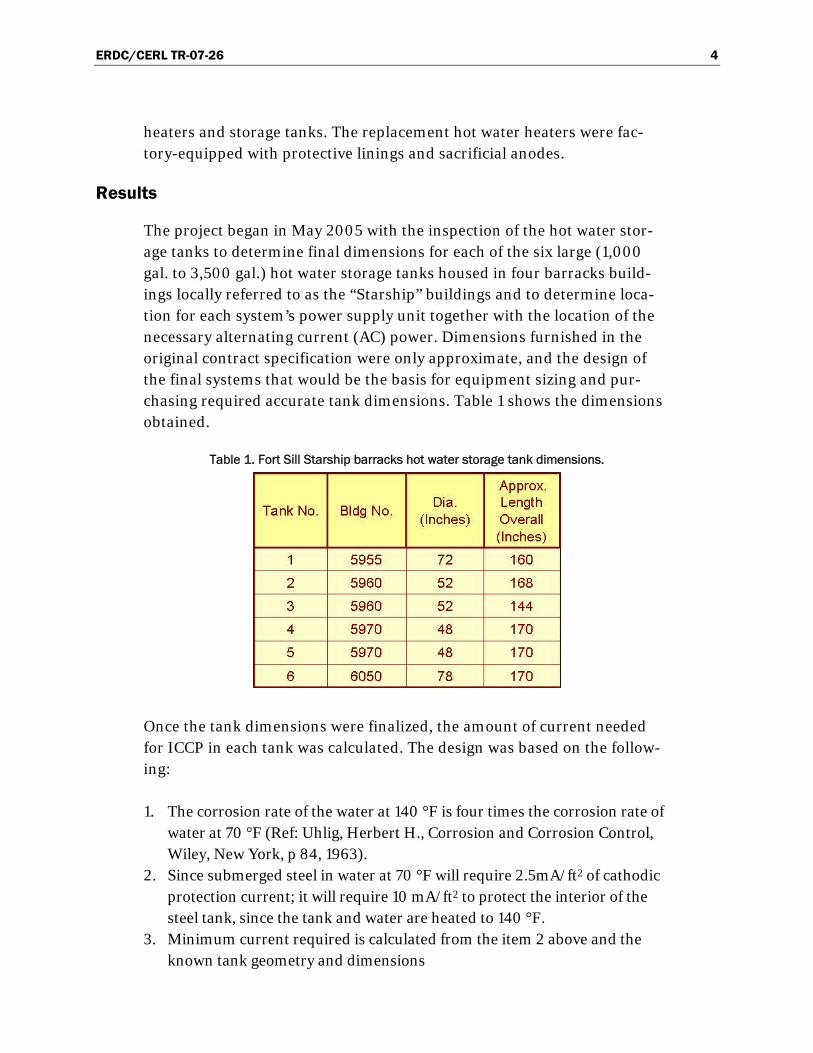
The project began in May 2005 with the inspection of the hot water stor-age tanks to determine final dimensions for each of the six large (1,000 gal. to 3,500 gal.) hot water storage tanks housed in four barracks build-ings locally referred to as the “Starship” buildings and to determine loca-tion for each system’s power supply unit together with the location of the necessary alternating current (AC) power. Dimensions furnished in the original contract specification were only approximate, and the design of the final systems that would be the basis for equipment sizing and pur-chasing required accurate tank dimensions. Table 1 shows the dimensions obtained.
Table 1. Fort Sill Starship barracks hot water storage tank dimensions.
Once the tank dimensions were finalized, the amount of current needed for ICCP in each tank was calculated. The design was based on the follow-ing:
1. The corrosion rate of the water at 140 °F is four times the corrosion rate of water at 70 °F (Ref: Uhlig, Herbert H., Corrosion and Corrosion Control, Wiley, New York, p 84, 1963).
2. Since submerged steel in water at 70 °F will require 2.5mA/ft2 of cathodic protection current; it will require 10 mA/ft2 to protect the interior of the steel tank, since the tank and water are heated to 140 °F.
3. Minimum current required is calculated from the item 2 above and the known tank geometry and dimensions
ERDC/CERL TR-07-26 5
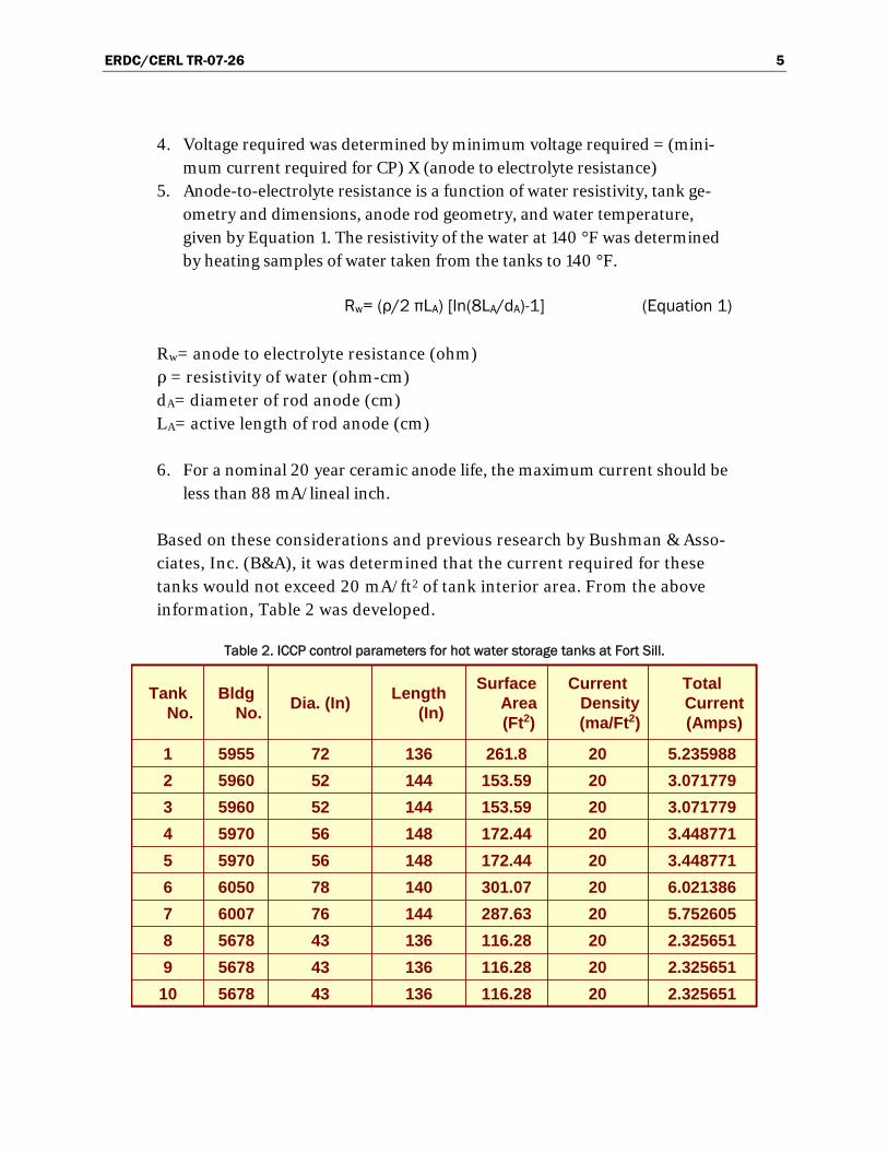
4. Voltage required was determined by minimum voltage required = (mini-mum current required for CP) X (anode to electrolyte resistance)
5. Anode-to-electrolyte resistance is a function of water resistivity, tank ge-ometry and dimensions, anode rod geometry, and water temperature, given by Equation 1. The resistivity of the water at 140 °F was determined by heating samples of water taken from the tanks to 140 °F.
Rw= (ρ/2 πLA) [ln(8LA/dA)-1] (Equation 1)
Rw= anode to electrolyte resistance (ohm) ρ = resistivity of water (ohm-cm) dA= diameter of rod anode (cm) LA= active length of rod anode (cm)
6. For a nominal 20 year ceramic anode life, the maximum current should be less than 88 mA/lineal inch.
Based on these considerations and previous research by Bushman & Asso-ciates, Inc. (B&A), it was determined that the current required for these tanks would not exceed 20 mA/ft2 of tank interior area. From the above information, Table 2 was developed.
Table 2. ICCP control parameters for hot water storage tanks at Fort Sill.
2.32565120116.28136435678102.32565120116.2813643567892.32565120116.2813643567885.75260520287.6314476600776.02138620301.0714078605063.44877120172.4414856597053.44877120172.4414856597043.07177920153.5914452596033.07177920153.5914452596025.23598820261.81367259551
Total Current (Amps)
Current Density (ma/Ft2)
Surface Area (Ft2)
Length(In)Dia. (In)Bldg
No.Tank
No.

ERDC/CERL TR-07-26 6
Following the above, the ICCP design calculations for Tank No. 1 in Build-ing No. 5955, as shown below, typify the design process used for each tank (Tables 3 and 4).
Table 3. Bare steel ICCP anode resistance and current parameters for hot water storage tanks at Fort Sill.

ERDC/CERL TR-07-26 7
Table 4. ICCP current output with control parameters and anode life for hot water storage tanks at Fort Sill.
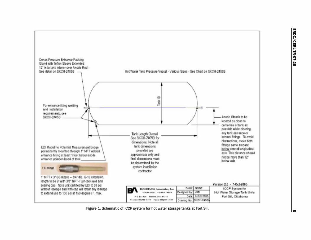
Following the above design calculations, the design sketches shown in Fig-ures 1 and 2 were prepared for use by the specialized cathodic protection installation contractor.
ERD
C/C
ERL TR
-07-26 8
Figure 1. Schematic of ICCP system for hot water storage tanks at Fort Sill.
C_ I'lonIWII EI'fr...et PII:liI\I GIin' d TtIo!I !iJtf'IIt f.ct!KIH 12' 11110 lMlirUflo! OWl AMOe 1t0CI -S .. detIiI OIl &KCtf.2«!5a .~
ing lil'd\g ..
... I f\ N
~OIlI1r __ ft IrICII ~k.OI '*qLI""'**, SKCIf.J4058
,
~Ue.~~ rot WocieI Fe Pv ............. MllliICe III""IIM
!tIw;III' tf'T ,....... Ie!m I bII below .... 1111 .. __ 011 ~_GlIi!M
l ' NPT A T SS ". - 314' i ii. G-l0 tJlMtlol~, Ien;11 fit h i' 'll:lI l 'll' NPT.f )uIIcbI WIll and ~ 1'.$ Noll! IIl'IiI certld ~ EOIIil 50 poIj . 'fIo:A Inkag. 1M w.ell till wi retlin " MI'~ 10 txtenI · ... 1O 150jW 1oI1S04qeeaf n'WI.
,. • • •
9
!
T"'~Om" Se~ SKDf-24® b ., ...... '"'- NcIe .. _., ......
....... -~II only and fNI '_0lIl m..st
. O,:\1I14Q1. • • , ....... -",-... ,' .. " '" ........ . ........ .. ," "N' ''Mj'''."" '" ,,,.,,,,.,,,,
'"
... /
'" ..
r- ,I,nodo Glardl tI be Ioc.nd • r;be I>
Dell:. ...... 01 tri fi ~"""!!hIe dI-"II any IInI. "~1rIaO 01 .. "'mil i!IttngI: TD .\IOI~ '*'"rr..d0t05.. III •• " bQch fdo9i: ume .mo<n: I!!!Iz!. _lIlo!9tu:lin., a.dc. TIiI dkunce d!oM "'" lit I'!KIIt ill., 12'" t..br Iri<.

ERD
C/C
ERL TR
-07-26 9
Figure 2. Schematic of ICCP system for hot water storage tanks at Fort Sill showing detail of anode installation and electrical connections.
112" In~ ~ 11YW veg:e1 per.e:r.,-JOI\ I:tnoJ ~ IiIeI wAAll on OIa*ofW*~yASME Cert.1ied Pm.~V~W~ BoI:h1lt:ng and weld mlli! be ,~lot lISe on AS~tE prenure veuel opera:ng aI up to 1 50 psi iI:emaI pre$t....e (AS,": Pren :.e Vesul Ra:lli crI TII1I.} ___ J
/-- ~1O crI typlCll Corw: ~ .I!!!I. tIre.I:ied one end cnIy ~ w.:tl flO
TeOon i.Iee'Je 0'ffl4flOde lOcI
IL":H!>"'-~ • As-a..-, ..... ..... .... fO. , .. , .... • • •• , '" ., .... 0._ .... "
...... , .. ". .... , . ... <"",,, .... ,
4' too.nd ~e.;I ooncI.t(ldl)wll Ihre~ CO'o'eI' ",,1 calil l-l hlb «Wl:.t:tmg ta\I'Io!CtaIlrom Rea.f.er pOCitve IffiI W7t 10 ' ''9 I'JII9 COO'II'IetIlOtl to.':ed iI plate ID ir.readed eM of 4rW tOIl e:r.enr:ll\Oi in:o
Mililr.Y!!I " I~ AI'iG "ran:Sed C\?9I*, type RHWIUSE $lyle RR tI)'pakwI rlb~ lMuIa:ed '1$te:'l1 DC posiWe feed W.le tom CatIIod:c ProIectJon ~f~ • .v'ICIde lenIlna
.... ""' ~,.....""'" .:11 s.s o.oI)r >ntI ....... h .. :~"~tMo. (PIN lrOl:l3-01 4).~
iI:o~o.o. OIiNll l /2" >ntI.",.., .. llr .... l..M .-.1. SNI....".",_ T __ ",taM"'" v ........... . .wtor ....................... "''00 __ , GlaorI " ~lrr
""*,.,.-,,,,-.

ERDC/CERL TR-07-26 10
The above ICCP system design incorporated the following unique charac-teristics:
None of the hot water tanks had man-way access fittings to permit work from the inside of each tank. Each system was thus designed to use flexible and joinable ceramic coated anode rods, which allowed them to be bent and inserted into the tanks in 4-ft-long segments. This avoided having to break out any walls to provide clearance for their installation. Subsequent segments would be screw coupled to the first and subsequent segments as the assembly was pushed into the tank until the far end of each horizontal tank was reached (four or five segments were required for each tank).
Insertion and penetration of the anode rod at each end of the tank was to be made through a 1-in.-diameter “weld-o-let” fittings that would be welded in place from the exterior on opposite ends of each tank. These provided threaded holes for high pressure SS “Conax” compression sealing elements minimizing the impact on the pressure vessel tank wall.
Setting the system output to provide effective corrosion control requires that the change in steel energy level be measured as a result of the applica-tion of cathodic protection current. This is done through the use of a refer-ence electrode which is placed in contact with the water inside the hot wa-ter storage tank coupled to a director current (DC) voltmeter, which is also connected to the tank structure. Most typically, the reference electrode of choice is the Copper-Copper Sulfate type commonly referred to as CSE. Unfortunately, these tanks are sealed vessels operating under 50 to 100 pounds internal pressure and the stored water is at a temperature of ap-proximately 140 degrees F. No manufacturer of CSE reference electrodes could be found that would guarantee the accuracy of a permanently in-stalled cell in this environment. Thus, a capillary pore tube measurement port or bridge was designed into the system that facilitates taking these measurements with the cell located outside the hot water tank with the tip held against the ionically conductive capillary tube.
Since a permanent CSE could not be used, automatic potential control rec-tifiers were not considered for use on this project. Instead, voltage control systems were selected wherein the adjustment of the applied system volt-age is adjusted by a single dial operating a power rheostat.
ERDC/CERL TR-07-26 11
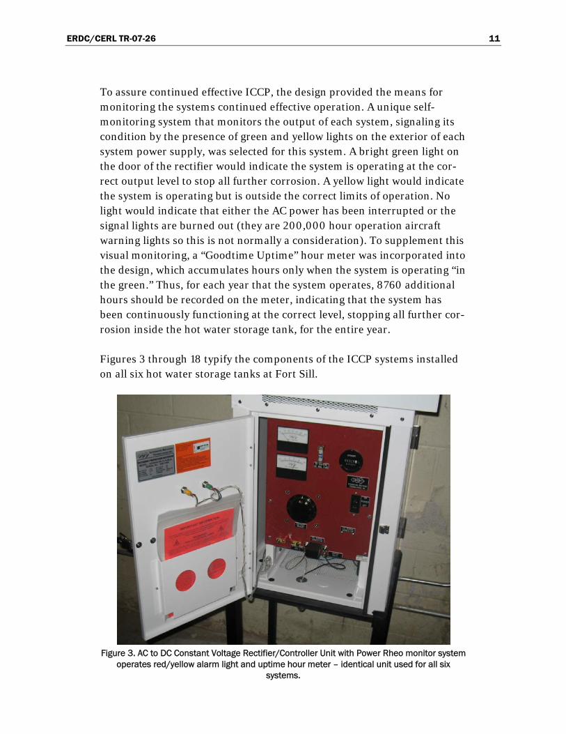
To assure continued effective ICCP, the design provided the means for monitoring the systems continued effective operation. A unique self-monitoring system that monitors the output of each system, signaling its condition by the presence of green and yellow lights on the exterior of each system power supply, was selected for this system. A bright green light on the door of the rectifier would indicate the system is operating at the cor-rect output level to stop all further corrosion. A yellow light would indicate the system is operating but is outside the correct limits of operation. No light would indicate that either the AC power has been interrupted or the signal lights are burned out (they are 200,000 hour operation aircraft warning lights so this is not normally a consideration). To supplement this visual monitoring, a “Goodtime Uptime” hour meter was incorporated into the design, which accumulates hours only when the system is operating “in the green.” Thus, for each year that the system operates, 8760 additional hours should be recorded on the meter, indicating that the system has been continuously functioning at the correct level, stopping all further cor-rosion inside the hot water storage tank, for the entire year.
Figures 3 through 18 typify the components of the ICCP systems installed on all six hot water storage tanks at Fort Sill.
Figure 3. AC to DC Constant Voltage Rectifier/Controller Unit with Power Rheo monitor system
operates red/yellow alarm light and uptime hour meter – identical unit used for all six systems.

ERDC/CERL TR-07-26 12
Figure 4. Reference Electrode Potential Monitoring Port with cap in place.
Figure 5. Precious metal oxide (ceramic) coated titanium rod entrance condulet with screw-off
cover plate.

ERDC/CERL TR-07-26 13
Figure 6. Typical floor rack-mounted ICCP rectifier. Note green light is on indicating unit is operating within design current limits.
Figure 7. Anode (¼-in. diameter) rod extending out of hot water storage tank with black insulation positive lead wire from ICCP rectifier unit attached. (Note white insulation wire is rectifier system negative ground wire).
ERDC/CERL TR-07-26 14
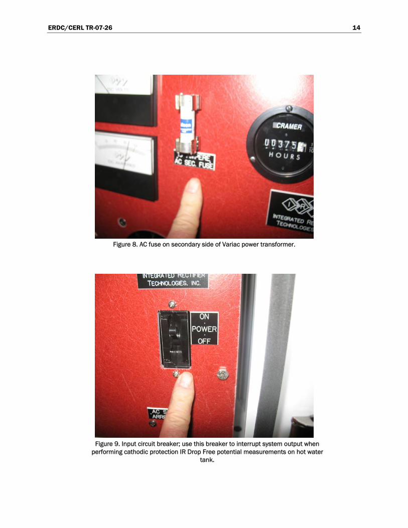
Figure 8. AC fuse on secondary side of Variac power transformer.
Figure 9. Input circuit breaker; use this breaker to interrupt system output when
performing cathodic protection IR Drop Free potential measurements on hot water tank.

ERDC/CERL TR-07-26 15
Figure 10. Digital “up-time” meter records accumulated hours system operating
with green-light on (system current within minimum/maximum limits set by corrosion engineer at time of last system annual performance tests).
Figure 11. Positive and negative terminals for measuring system DC voltage output– note positive (+) anode terminal is on right and system negative (-)
terminal is on left.
ERDC/CERL TR-07-26 16
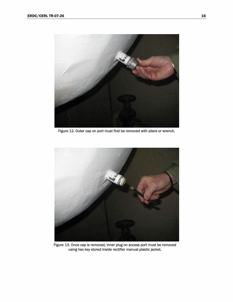
Figure 12. Outer cap on port must first be removed with pliers or wrench.
Figure 13. Once cap is removed, inner plug on access port must be removed
using hex key stored inside rectifier manual plastic jacket.

ERDC/CERL TR-07-26 17
Figure 14. To facilitate contracting the osmotic conductor side of the port, cotton or
paper “wadding” is moistened and pushed down inside the port to the tip of a standard reference electrode placed in contact with the remaining portion of the
wadding sticking out of the port.
Figure 15. After carefully wiping dry the exterior of the port a calibrated Cu-
CuSO4 electrode is placed in contact with the moist wadding.

ERDC/CERL TR-07-26 18
Figure 16. The DC voltmeter positive lead is connected to the
reference electrode and the negative is connected to the structure.
Figure 17. Current output alarm circuit control and adjustment panel.

ERDC/CERL TR-07-26 19
Figure 18. Note green light is lit indicating that system DC current
output is within the range set at the last detailed annual corrosion / cathodic protection system effectiveness check-out of the system.
Other project-related documentation provided in this report are the con-tractor’s safety manual, and communications plan (Appendix A), the recti-fier manual and schematic (Appendix B), the ICCP system replacement parts list (Appendix C, and the Recommended Future Monitoring Data Sheets (Appendix D).
Initial testing, adjusting, and monitoring results
The final testing of the six ICCP systems to provide corrosion protection to the interiors of the hot water storage tanks was performed on 26–27 April 2006. Each system was inspected for proper installation, and the anode to structure resistance was measured using a Nilsson Model 400 AC Imped-ance Meter. This information would later prove invaluable when diagnos-ing the one system that was later found to have a defective Teflon insulat-ing sleeve. Potential measurements were made before energizing the system to establish the free (or static) corrosion potential. Only after these basic observations and tests was the system energized.

ERDC/CERL TR-07-26 20
Initial energization was made with the Variac voltage output set at its low-est value. Simultaneously, “On” and “Instant-Off” potentials were made. The Variac-controlled output was then slightly increased and both poten-tials were then measured again. At this point, 5 minutes was allowed to pass and then both the “On” and “Instant-Off” potentials were again measured. If the potentials measured were still below the desired criteria, the process was repeated until the values approached the criteria level. If the “Instant-Off” value was approaching the NACE International criterion for protection of -0.850 Volts DC (IR Drop Free Instant Off Criterion) with respect to the CSE, the system was allowed to operate at this value for an-other 30 minutes and the measurements were made once again. Usually by this time, the “Instant-Off” value would slightly exceed -0.850 Volts at which point in time the system was considered to be final adjusted for op-eration.
The final adjustment of the system involved setting the upper and lower alarm limits so that they would display a “GREEN” light so long as the rec-tifier was putting out the DC current equivalent to the final set current with plus/minus 1 ampere.
After final adjustment, the data for each system was recorded as follows (Table 5).

ERDC/CERL TR-07-26 21
Table 5. Fort Sill hot water storage tank ICCP system final checkout.
Building No. 5955 5960 5960 5970 5970 6050Tank No. 1 1 2 1 2 1
Tank Dia. (inches) 72 52 52 48 48 78Tank Length (Inches) 160 168 144 170 170 170
Rectifier Mfg. IRT IRT IRT IRT IRT IRT
Rectifier Model No. ADASAS 50-12 AbMzQa
ADASAS 50-12 AbMzQa
ADASAS 50-12 AbMzQa
ADASAS 50-12 AbMzQa
ADASAS 50-12 AbMzQa
ADASAS 50-12 AbMzQa
Rectifier Serial No. 05R-1089 05R-1091 05R-1092 05R-1093 05R-1090 05R-1088Rated AC Volts 115 115 115 115 115 115
Rated AC Amps 8.23 8.23 8.23 8.23 8.23 8.23Rated DC Volts 50 50 50 50 50 50
Rated DC Amps 12 12 12 12 12 12Date: 4/26/2006 4/26/2006 4/26/2006 4/26/2006 4/26/2006 4/26/2006
Hour Meter Reading:Monitor Light (Greeen, Yellow or None:
Variac Set Point (0 to 100): 7 6DC Amps (Rectifier Meter): 9.6 2 1.2 0.6 0.8 1DC Volts (Rectifier Meter): 3 7 5 4 7 5
DC Amps (VOM Meter): 10.11 1.923 4.84 0.561 0.714 0.651DC Volts (VOM Meter): 3.135 6.52 1.7505 3.63 6.462 4.038
ON Potential (-mV): 1.08 1.1296 1.026 0.884 0.827 1.039INSTANT-OFF Potential (-mV): 0.8745 0.9278 0.86 0.846 0.746 0.956
Anode to Structure AC Resistance (Ohms) 0.49 6.3 2.7 2.8 2.7 2.7Low Current Alarm Set Point (0 - 100): n/a n/a n/a n/a n/a n/aHigh Current Alarm Set Point (0 - 100): n/a n/a n/a n/a n/a n/a
Hour Meter Reading: 3.0 3.0Monitor Light (Greeen, Yellow or None: Green Green Green Green Green Green
Variac Set Point (0 to 100): 14 14 10DC Amps (Rectifier Meter): 9.6 2 1.2 1.2 2.3 1DC Volts (Rectifier Meter): 3 7 5 6 8 5
DC Amps (VOM Meter): 10.11 1.923 4.84 1.2 0.651DC Volts (VOM Meter): 3.135 6.52 1.7505 6 4.038
ON Potential (-mV): 0.901 1.1296 1.028 1.44 1.039INSTANT-OFF Potential (-mV): 0.84 0.9278 0.863 0.85 0.956
Low Current Alarm Set Point (Amps): n/a 5 6 4 6 5High Current Alarm Set Point: n/a 20 24 28 28 22
System Comments:
Potential readings erratic and sometimes
too low for complete protection
Left Rectifier and Left Tank when looking at tank ends with monitor
ports
Right Rectifier and Right Tank when looking at tank ends with monitor
ports
Left Rectifier and Left Tank when looking at tank ends with monitor
ports
Right Rectifier and Right Tank when looking at tank ends with monitor
ports
Required Repairs:
Anode may be shorted to structure -
remove and replace after repair - Hi & Low Limits need to be
reset
None None None None None
Fort Sill Hot Water Storage Tank Impressed Current Cathodic Protection System Final Check Out
Bas
e Sy
stem
Dat
aD
ata
at E
nd o
f Tes
ting
Dat
a O
n A
rriv
al fo
r Tes
ting
The systems have continued to operate with one minor component correc-tion from the date of installation until the date of this report. The correc-tion involved replacing a Teflon seal sleeve that was defective at time of installation. A repair sleeve had to be ordered. Nonetheless, the system was put into operation with the defective sleeve and was able to provide fully effective, albeit reduced power efficient, corrosion control in the sin-gle system with this problem. The repair was accomplished 1 month later after the part was acquired and the work could be scheduled over a week-end convenient to all parties involved. All five other systems have func-tioned flawlessly since their initial operation in April 2006. Currently all

ERDC/CERL TR-07-26 22
six systems are operating as designed and all have provided complete cor-rosion control since their original installation (See Tables 6 and 7).
Table 6. Data from hot water tank with defective Teflon sleeve BEFORE repairs on 22 July 2006.
Building No. 5955Tank No. 1Tank Dia. 72
Tank Length 160Rectifier Mfg. IRT
Rectifier Model No. ADASAS 50-12 AbMzQa
Rectifier Servial No. 05R-1089 Rectifier Rated AC Volts 115
Rectifier Rated AC Amps 8.23 Rectifier Rated DC Volts 50
Rectifier Rated DC Amps 12
Date and Time on Arrival: 7/22/2006 18:35Hour Meter Reading on Arrival 2467 Hours
Monitor Lite on Arrival (Yellow, Green or None) GreenVariac Set Point on Arrival (0 to 100) 10 %
DC Amps on Arrival 9 AmperesDC Volts on Arrival 3.5 Volts
ON Potential vs Cu-CuSO4 on Arrival 0.972 VoltsINSTANT-OFF Potential vs Cu-CuSO4 on Arrival 0.848 Volts
Low Current Alarm Set Point on Arrival 3 O'clock AmperesHigh Current Alarm Set Point on Arrival 1 O'clock Amperes
Anode to Structure Resistance on Arrival (4 Contact AC Impedance Method) 0.47 Ohms
System Negative to Structure Resistance on Arrival (4 Contact AC Impedance Method) 0.038 Ohms
Anode to System Negative Resistance on Arrival (4 Contact AC Impedance Method) 0.515 Ohms
Table 7. Data from hot water tank with defective Teflon sleeve AFTER repairs on 22 July 2006.
Variac Set Point at Departure (0 to 100) 11DC Amps at Departure 1.8 AmperesDC Volts at Departure 7 Volts
ON Potential vs Cu-CuSO4 at Departure 1.047 VoltsINSTANT-OFF Potential vs Cu-CuSO4 at Departure 0.852 Volts
Low Current Alarm Set Point 7 O'clockHigh Current Alarm Set Point 2 O'clock
Monitor Lite at Departure (Yellow, Green or None) GreenHour Meter Reading at Departure 2468 Hours
Anode to Structure Resistance at Departure(4 Contact AC Impedance Method) 4.4 Ohms
System Negative to Struct. Resistance at Departure(4 Contact AC Impedance Method) 0.036 Ohms
Anode to System Negative Resistance at Departure(4 Contact AC Impedance Method) 4.44 Ohms
Date and Time at Departure: 7/22/2006 1:35
Re-measured on 7/23/06 10:30; i.e. after tank refilled and water allowed to heat up overnight
After tank refilled - cold water
After tank refilled - cold water
After tank refilled - cold water

ERDC/CERL TR-07-26 23
Note the dramatic increase in Anode to System resistance after repair of Teflon sleeve from 0.515 ohms (before repair) to 4.44 ohms. In addition, current required for complete protection has been reduced from 9.0 am-peres to 1.8 amperes. A repair report is given in Appendix E.
Installation of new replacement water heaters and tanks
Seventeen new hot water heaters and hot water storage tanks, ranging in size from 37 to 1,138 gallons, were installed to replace the leaking tanks in selected buildings as shown in Table 8 and Figure 19. The tanks and hot water heaters were purchased from A. O. Smith and installed by F. G. Haggerty, Inc., Wichita Falls, TX.
Table 8. New replacement hot water heaters and tanks at Fort Sill.
# Bldg # Item
1 1607 37 gal hot water heater
2 1607 37 gal hot water heater
3 2470 37 gal hot water heater
4 5673 37 gal hot water heater
5 5672 37 gal hot water heater
6 2428 37 gal water heater
7 5690 40 gal hot water heater
8 5690 120 gal tank
9 2812 275 gal tank
10 1607 500 gal hot water heater
11 1605 600 gal hot water heater
12 2812 855 gal tank
13 1616 855 gal tank
14 1616 855 gal tank
15 2470 908 gal tank
16 1603 1,100 gal tank
17 5690 1,138 gal tank
ERDC/CERL TR-07-26 24
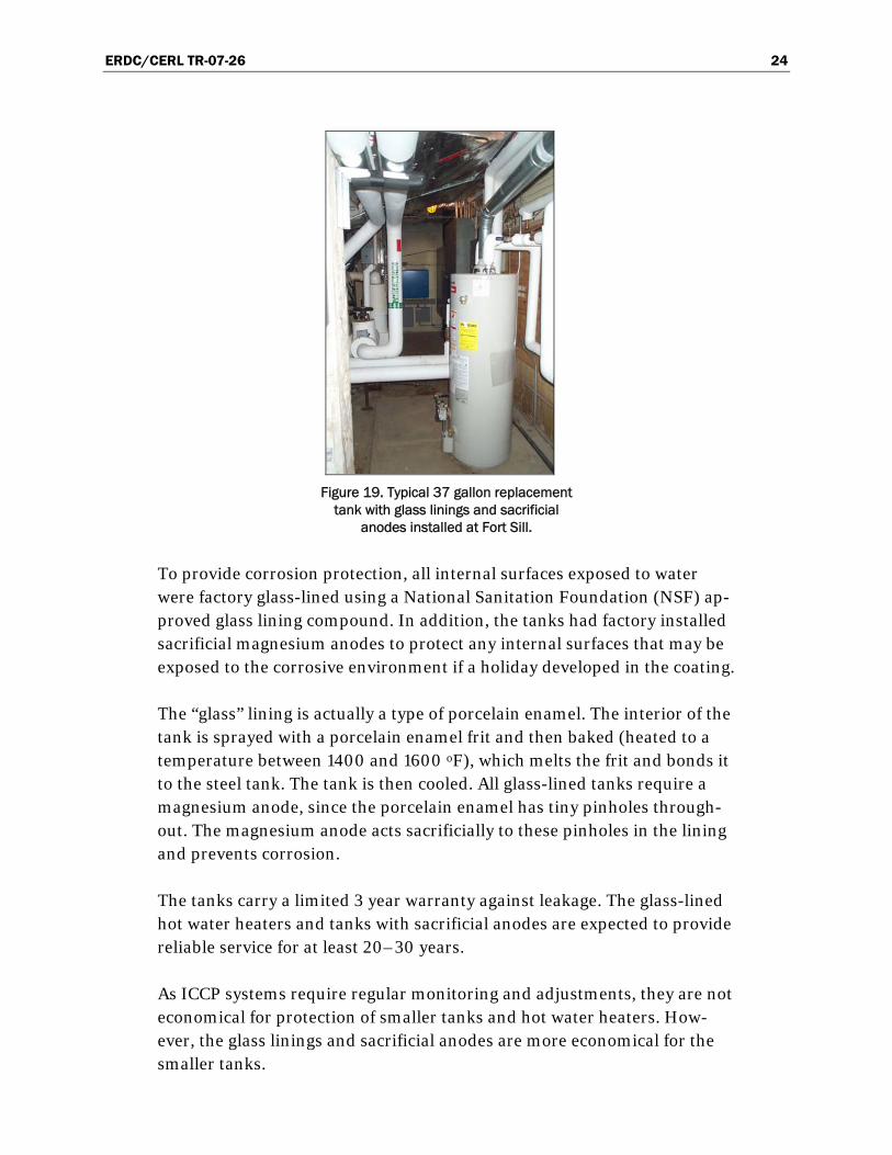
Figure 19. Typical 37 gallon replacement
tank with glass linings and sacrificial anodes installed at Fort Sill.
To provide corrosion protection, all internal surfaces exposed to water were factory glass-lined using a National Sanitation Foundation (NSF) ap-proved glass lining compound. In addition, the tanks had factory installed sacrificial magnesium anodes to protect any internal surfaces that may be exposed to the corrosive environment if a holiday developed in the coating.
The “glass” lining is actually a type of porcelain enamel. The interior of the tank is sprayed with a porcelain enamel frit and then baked (heated to a temperature between 1400 and 1600 oF), which melts the frit and bonds it to the steel tank. The tank is then cooled. All glass-lined tanks require a magnesium anode, since the porcelain enamel has tiny pinholes through-out. The magnesium anode acts sacrificially to these pinholes in the lining and prevents corrosion.
The tanks carry a limited 3 year warranty against leakage. The glass-lined hot water heaters and tanks with sacrificial anodes are expected to provide reliable service for at least 20–30 years.
As ICCP systems require regular monitoring and adjustments, they are not economical for protection of smaller tanks and hot water heaters. How-ever, the glass linings and sacrificial anodes are more economical for the smaller tanks.

ERDC/CERL TR-07-26 25
4 Metrics
Metrics for this project are based on historical information on corrosion problems with the hot water storage tanks, as well as monitoring the per-formance data of the ICCP systems.
According to the Fort Sill DPW Office, there are at least 84 documented cases of corroded and leaking hot water storage tanks and hot water heat-ers. For tanks of the large hot water storage tanks, similar to those that were cathodically protected as part of this demonstration and implementa-tion projects, it is estimated that the cost of disconnecting, removing, re-connecting new tanks, and rebuilding the walls is on the order of $150,000 per tank, therefore these corrosion protection technologies are needed
In order to verify that the ICCP systems are properly working in the six hot water storage tanks, National Association of Corrosion Engineers (NACE) International Standards were applied. The cathodic protection systems ef-fectiveness in controlling corrosion on the interior of the Fort Sill hot wa-ter storage tanks are monitored using potential measurements made using a calibrated (+/- 2 mV) saturated copper-copper sulfate reference elec-trode. The measurement is made within 500 milliseconds after the output of the system is manually interrupted by tripping the system power supply (rectifier) AC breaker and observing and recording the second digital value displayed on a precision calibrated digital DC voltmeter. NACE Interna-tional's criteria for complete corrosion mitigation is that the structure po-tential, when measured in this manner, is confirmed on buried and sub-merged steel structures (RP-01-69) when this value is -850 mV or more negative. The value can be re-measured monthly to assure the value re-mains at this protective level. An additional system check is provided by the integral sealed "up-time" meter that records the total number of hours, on a continuing basis, when the system output is within the mini-mum/maximum output values that testing has confirmed will maintain the protective potential at the NACE criteria. A third check involves the system monitor lights that only display a “green” light condition when the NACE criteria is satisfied. All ICCP systems that have been implemented meet these criteria, and will be monitored for at least 1 year from the date of installation in order to ascertain that they continue to meet the criteria.

ERDC/CERL TR-07-26 26
5 Economic Summary
Base contract costs
An economic analysis for implementation of the custom-designed ICCP systems in the large tanks and for replacement of the existing leaking smaller tanks with commercially available glass lined hot water storage tanks and hot water heaters is presented. The total contract cost for this project including project management, engineering design, system materi-als and labor to install ICCP systems and risks assessment was $103,524 or $17,254 per tank for the six large hot water storage tanks. Given that the design would not have to be done again and that the risks involved with undertaking a project with significant unknowns would be eliminated on future efforts of this type, the costs per tank could be reduced to approxi-mately $11,000 to $12,000 per tank. If the systems were to be installed at the same time the hot water tanks are being installed, this cost could be reduced further to approximately $8,000 to $9,000 per tank. The total cost for the replacement of the 17 smaller tanks and hot water heaters with commercially available glass lined tanks and hot water heaters was $280,500 or $16,500 per tank.
ROI analysis
The projected return on investment (ROI) for this project was determined by assessment of the project costs and projected cost avoidance due to im-plementation in accordance with the recommended procedure based on Appendix B of OMB Circular A94. The projected ROI was found to be to be 8.6. Further details of these ROI calculations for this project are given in Appendix F. The ROI analysis was validated by Burke Associates, and is also shown in Appendix F.

ERDC/CERL TR-07-26 27
6 Recommendations
1. ICCP should be considered for retrofitting in all large (grater than 1,000 gal.) hot water storage tanks, especially where the cost of removal is high due to requirements for disconnection of complex plumbing and re-plumbing of numerous water lines that service the tank.
2. A monthly monitoring system for ICCP systems with ceramic anodes, similar to the system implemented at Fort Sill is considered fundamental to long term corrosion protection of the large hot water storage tanks.
3. Smaller hot water heater and hot water storage tanks (37 gal. to 1,000 gal.) should be procured with factory-installed glass linings in conjunctions sac-rificial anodes.

ERDC/CERL TR-07-26 28
7 Implementation
The use of ceramic anodes for retrofitting ICCP in large (greater than 1,000 gal) hot water storage tanks is recommended for Army and DoD In-stallations. New smaller (37 – 1,000 gal) hot water tanks and hot water heaters should be procured with factory installed glass linings in conjunc-tions sacrificial anodes.
Future plans are to recommend that the existing UFGS 15556A: “Forced Hot Water Heating Systems Using Water and Steam Heat Exchangers” be revised to include specifications on implementation of these ceramic an-ode-based cathodic protection systems for hot water storage tanks.

ERDC/CERL TR-07-26 29
8 Conclusions
Custom designed ceramic anodes were retrofitted as part of an ICCP sys-tem to for six large 1,000 to 3,500 gallon hot water storage tanks that ser-vice the “Starship” Barracks and adjoining mess halls. The cathodic pro-tection systems were designed to provide corrosion protection to the bare steel interior of the tanks that are susceptible to corrosion. This project represented the first time horizontal anodes for an ICCP were installed in ASME pressure vessel hot water storage tanks with no man-ways.
These cathodic protection systems have continued to operate as designed since their initial operation in April 2006. They have provided complete corrosion control since their original installation. Onsite training on the operation and monitoring of these systems was provided to the Fort Sill DPW maintenance personnel. Specifications for the anodes and rectifiers and design specifications for these systems were provided.
The lifetimes of the large tanks are expected to be extended by 30 years as a result of installing cathodic protection systems using ceramic coated (mixed metal oxide) anodes. The newly installed smaller tanks and hot wa-ter heaters with the glass linings and sacrificial anodes are expected to last 20–30 years.
Seventeen existing and already leaking smaller (37 to 1,000 gal.) tanks and hot water heaters were replaced with new tanks and hot water heaters. The new tanks and hot water heaters were factory-equipped with glass linings and sacrificial anodes. For the 17 smaller tanks, it was shown that the glass linings and sacrificial magnesium anodes were more economical for corro-sion protection, than ICCP systems, due to the reduced need for monitor-ing and maintenance .

ERDC/CERL TR-07-26 A1
Appendix A: Contractor’s Safety Manual and Communications Plan

B&A HEALTH & SAFETY MANUAL Fort Sill, OK CP Project
Ver. 4.0
BUSHMAN & Associates, Inc.
C O R R O S I O N C O N S U L T A N T S
P.O. Box 425, Medina, OH 44258 Phone 330/769-3694, Fax 330/769-2197
Website: www.bushman.cc

Bushman & Associates Health and Safety Manual
May 2005
TABLE OF CONTENTS PAGE
General Information.............................................................................................................. 1
Safety and Health Responsibilities...................................................................................... 3
Management.................................................................................................................... 3
Supervisors...................................................................................................................... 3
Employees........................................................................................................................ 3
Personal Work Rules............................................................................................................. 5
General Safety Rules............................................................................................................. 6
Safety Disciplinary Policy.................................................................................................... 8
Ladders/Training Safety Rules........................................................................................... 9
Fall Protection Rules and Training Guide.......................................................................... 12
Scaffold Safety Rules............................................................................................................. 20
Motorized Vehicles and Equipment Safety Rules.............................................................. 21
Trenching and Excavating Safety Rules.............................................................................. 22
Hazard Communication Program....................................................................................... 23
Purpose............................................................................................................................. 23
Procedure......................................................................................................................... 23
Container Labeling......................................................................................................... 23
Material Safety Data Sheets................................................................................................. 24
Hazard Non-Routine Tasks.......................................................................................... 25
Employee Orientation Checklist – Hazardous Substances.............................................. 26
First Aid Training, Kits, and Posters................................................................................... 27
Safety Bulletin Board............................................................................................................. 27
First Aid Procedures in Construction ................................................................................. 28
Procedure for Injury or Illness on the Job........................................................................... 28
Occupational Injury and Illness Recordkeeping................................................................ 30
Accident Investigation and Reporting................................................................................ 31
How to Hold a Good Safety Meeting.................................................................................. 32
Crew Leader Meetings.......................................................................................................... 33
Appendices of Standard Forms, Checklists and Guides........................................ 34 – 55

Bushman & Associates Health and Safety Manual
Page 1 of 60 May 2005
GENERAL INFORMATION OVERVIEW Industrial injury accidents create a no-win situation for everyone involved. Employees experience pain, suffering and incapacitation while the company suffers from the loss of the injured person's contributions. This document provides information and guidance for the establishment and maintenance of an accident-free work environment. PROCEDURES The appendixes to this directive contain guidance for safety procedures to be followed, and forms to be used. Supervisors are expected to integrate the procedures into the appropriate work activity and employees are expected to apply them on the job. The sample forms are to be used if they apply to the job concerned. A copy of this statement will be issued to all supervisory and management personnel. A copy of the policy statement will give to each employee. REGULATIONS A copy of the following documents will be maintained on each job site:
Bushman & Associates Safety Manual
OSHA Safety and Health Standards (29 CFR 1926 - Construction and 29 CFR 1910 – General Industry)
Bushman & Associates Health and Safety Manual
Page 2 of 60 11/2/02
SAFETY AND HEALTH POLICY The purpose of this policy is to develop a high standard of safety throughout all operations of Bushman & Associates and to provide guidelines so employees are not required to work under conditions that are hazardous or unsanitary. Employees have the right to derive personal satisfaction from their jobs. The prevention of occupational injury or illness is central to this belief that it will be given top priority at all times. It is Bushman & Associates’s goal to initiate and maintain complete accident prevention and safety training programs. Each individual is responsible for the safety and health of those persons in their charge and co-workers around them. By accepting mutual responsibility to operate safely, we will all contribute to the well being of personnel.
_____________________________________ James B. Bushman, President

Bushman & Associates Health and Safety Manual
Page 3 of 60 11/2/02
SAFETY AND HEALTH RESPONSIBILITIES Responsibility for safety and health include the establishment and maintenance of an effective communication system between workers, supervisors and management. To this end, all personnel are responsible to make sure that their messages are received and understood by the intended receiver. Specific safety and health responsibilities for personnel are as follows: MANAGEMENT OFFICIALS: Active participation in and support of safety and health programs is essential. Managers will display interest in safety and health matters. At least one manager (as designated) will participate in project safety and health meetings, accident investigations and job site inspections. Each manager will establish realistic goals for accident reduction in his/her area of responsibility and will establish the necessary implementing instructions for meeting the goals. Goals and implementing instructions shall be within the framework established by this document. SUPERVISORS: The safety and health of the employees they supervise is a primary responsibility of supervisors. To accomplish this obligation, supervisors will: Conduct pre-job safety orientations with all workers to outline safety and health
rules, regulations and policies. Review rules as the job or conditions change or as required.
Require the proper care and use of all required protective equipment.
Identify and eliminate job hazards through job safety analysis procedures.
Inform and train all employees on the hazardous chemicals they MAY encounter
under normal working conditions or during an emergency situation. Conduct crew/leader meetings the first five minutes of each work shift to discuss
safety matters and work plans for the work day. Receive and take initial action on employee suggestions, awards or disciplinary
measures. Train all employees in the safe and efficient methods of accomplishing each job or
task. Review accident trends and establish prevention measures.

Bushman & Associates Health and Safety Manual
Page 4 of 60 11/2/02
Attend safety meetings and actively participate in the proceedings. Participate in investigations and inspections on safety and health related matters.
Promote employee participation in the safety and health program.
Actively follow the progress of injured workers and display an interest in their
rapid recovery and return to work. The Department of Labor & Industries can assist you in developing a program to effectively follow and manage injury claims.
EMPLOYEES: Observe the items of responsibility established in this document as well as job safety rules, which may apply to specific task assignments.
EMPLOYEE SAFETY AND HEALTH RESPONSIBILITIES
Report all on the job injuries promptly.
Report all equipment damage to your supervisor immediately.
Don’t take chances – use your safety equipment as directed.
Follow instructions – ask questions of your supervisor if required.
Observe and comply with all safety signs and regulations.
Report all unsafe conditions or situations that are potentially hazardous.
Operate only equipment you are qualified to operate. When in doubt, ask for directions.
Talk to management about problems that affect your safety or work conditions.
The most important part of this program is the individual employee – You! Without your cooperation, the most stringent program can be ineffective. Protect yourself and your fellow worker by following the rules. Remember: Work safely so you can go home to your family and friends. Don’t take chances – THINK SAFETY FIRST!

Bushman & Associates Health and Safety Manual
Page 5 of 60 11/2/02
PERSONAL WORK RULES
Report every injury, no matter how slight, to your supervisor immediately.
Horseplay, fighting, gambling, possession of firearms and possession or use of
alcoholic beverages or drugs, except as prescribed by a qualified physician, are strictly forbidden.
Running on any construction site is strictly prohibited except in extreme
emergencies. Wear clothing suitable for the weather and your work. Torn, loose clothing, cuffs,
sleeves, etc., are hazardous and could cause accidents. Jewelry (rings, bracelets, neck chains, etc.) shall not be worn.
Hard hats must be worn in all required areas. ANSI Class III Safety Vests will be
worn by all workers near Traffic Proper eye protection must be worn where you are exposed to flying objects, dust,
harmful rays, chemicals, flying particles, etc. Proper footwear must be worn on all construction sites; safety boots are highly
recommended. The wearing of sport shoes, sandals, dress shoes and similar footwear is strictly prohibited.
Always use gloves, aprons or other protective clothing when handling rough
materials, chemicals, and hot or cold objects. When spray painting, finish spraying, burning, exposed to large quantities of dust,
or to other toxic hazards, always wear the correct respirators as required. Special safety equipment is for your protection. Use it when required. Keep it in
good condition and report loss or damage of it immediately. 1. Hard hats will be provided for visitors to used when entering areas
designated as “Hard Hat Area.” They will be kept in the construction site office and to be returned when leaving.
2. Safety Glasses will be provided for visitors. They will be kept in the construction site office and to be returned when leaving.
3. Ear Protection 4. Subcontractors on site will be required to have their own equipment and use
it as required for safety.

Bushman & Associates Health and Safety Manual
Page 6 of 60 11/2/02
GENERAL SAFETY RULES
♦ Always store materials in a safe manner. Tie down or support piles if necessary to
prevent falling, rolling or shifting. ♦ Fall protection gear shall be used whenever working at 6 feet or hight above the
ground/floor in a space that is not properly pretected by guardrails and kick plates. If in question, review situation with Supervisor before proceeding with work.
Shavings, dust, scraps, oil or grease should not be allowed to accumulate. Good
housekeeping is a part of the job. Refuse piles must be removed as soon as possible. Refuse is a safety and fire
hazard. Remove or clinch nails in lumber that has been used or removed from a structure.
Immediately remove all loose materials from stairs, walkways, ramps, platforms,
etc. Do not block aisles, traffic lanes, fire exits, gangways or stairs.
Avoid shortcuts – use ramps, stairs, walkways, ladders, etc.
Standard guardrails must be erected around all floor openings and excavations
must be barricaded. Contact your supervisor for the correct specifications. Get help with heavy or bulky materials to avoid injury to you or damage to
material. Keep all tools and materials away from the edges of scaffolding, platforms, shaft
openings, etc. Do not use tools with split, broken or loose handles, burred or mushroomed heads.
Keep cutting tools sharp and carry all tools in a container. Know the correct use of hand and power tools. Use the right tool for the job.
All electrical power tools (unless double insulated), extension cords and
equipment shall be properly grounded. All electrical power tools and extension cords shall be properly insulated.
Damaged cords shall be replaced.

Bushman & Associates Health and Safety Manual
Page 7 of 60 11/2/02
Know the location/use of fire extinguishing equipment and the procedure for
sounding an alarm. Flammable liquids shall be used only in small amounts at the work site, in
approved safety cans. Proper guards or shields must be installed on all power tools before use. Do not
use any tools without the guards in their proper working condition. No “homemade” handles or extensions (cheaters) will be used!
Do not operate any power tool or equipment unless you are trained in its
operation and authorized by your firm to do so. Use tools only for their designed purpose.
Do not remove, deface or destroy any warning, danger sign or barricade, or
interfere with any form of accident prevention device or practice provided for your use or that is being used by other workmen.
All electrical power equipment and tools must be grounded or double insulated.
Use tools only for their designed purpose.
WALK-AROUND SAFETY INSPECTIONS Walk-around safety inspections will be conducted at the beginning of each job and at
least weekly thereafter. • The inspections will be conducted jointly by one member of management and one
employee, elected by the employees, as their authorized representative. • The inspections will be documented and the documentation will be made available
for inspection by representatives of the Department of Labor and Industries. • The records of the walk-around inspections will be maintained until the completion of
the job.
Bushman & Associates Health and Safety Manual
Page 8 of 60 11/2/02
SAFETY DISCIPLINARY POLICY
Bushman & Associates believes that a safety and health accident prevention program is unenforceable without some type of disciplinary policies. In order to maintain a safe and healthy workplace, employees must be aware of all company, State, and Federal safety and health regulations as they apply to specific job duties. The following disciplinary policy will be applied to all safety or health violations. The following steps will be followed unless the seriousness of the violation would dictate going directly to Step 2 or Step 3. 1. A first time violation will be discussed orally between a manager and the
employee under his/her supervision. This will be done as soon as possible. The purpose will be to educate the employee.
2. A second time offense will be followed up in written form and a copy of this
written documentation entered into the employee's personnel folder. 3. A third time violation will result in time off or possible termination, depending
upon the seriousness of the violation. This is per the personnel policy manual.
SAFETY DISCIPLINARY POLICY FOR SUBCONTRACTORS AND THEIR EMPLOYEES
The following steps will be followed unless the seriousness of the violation would dictate going directly to Step 2 or Step 3.
1. A first time violation will be discussed orally between site construction manager and
subcontractor/subcontractor employee to educate him/her on the safety issue. A note in the Daily Report is to be made. Subcontractor’s site manager to be informed for their safety meeting.
2. A second time offense by same subcontractor—a verbal reprimand followed up in
writing to the Subcontractor and noted in the Daily Report. This action is dependent upon the severity of the offence.
3. A third time violation for a major offence – the worker will be requested to leave the
job site and a call to the Subcontractor requiring this person to be replaced or not to return until permission is granted by Bushman & Associates .
Bushman & Associates Health and Safety Manual
Page 9 of 60 11/2/02
LADDER SAFETY RULES GENERAL
Inspect for physical defects before use.
Ladders are not to be painted except for numbering purposes.
Do not use ladders for skids, braces, workbenches or any purpose other than climbing.
When you are ascending or descending a ladder, do not carry objects that will prevent you from grasping the ladder with both hands.
Always face the ladder when ascending or descending.
If you must place a ladder over a doorway, barricade the door to prevent its use and post a warning sign.
Only one person is allowed on a ladder at a time.
Always keep both feet on the ladder rungs. Do not step laterally from a ladder onto another object.
Do not jump from a ladder when descending.
All joints between steps, rungs and side rails shall be tight.
Safety feet shall be in good working order and in place.
Rungs shall be free of grease and/or oil.
Fall protection gear shall be used whenever working at 6 feet or hight above the ground/floor in a space that is not properly pretected by guardrails and kick plates. If in question, review situation with Supervisor before proceeding with work.

Bushman & Associates Health and Safety Manual
Page 10 of 60 11/2/02
STRAIGHT TYPE OR EXTENSION LADDERS
All straight or extension ladders must be at least three feet beyond the supporting object when used as an access to an elevated work area.
After raising the extension portion of a two or more stage ladders to the desired height, check to be sure that the safety dogs or latches are engaged.
All extension or straight ladders must be secured or tied off at the top.
All ladders must be equipped with safety (non-skid) feet.
Portable ladders shall be used at such a pitch that the horizontal distance from the top support to the foot of the ladder is about one-quarter of the working length of the ladder.
STEPLADDERS
Do not place tools or materials on the steps or platform of a stepladder.
Do not use the top two steps or ladder cap of a stepladder as a step or stand.
Always level all four feet and lock spreaders in place.
Do not use a stepladder as a straight ladder.

Bushman & Associates Health and Safety Manual
Page 11 of 60 11/2/02
• All ladders must be equipped with safety (non-skid) feet.
• Portable ladders must be used at such a pitch that the horizontal distance from
the top support to the foot of the ladder is about one-quarter of the working length of the ladder.

Bushman & Associates Health and Safety Manual
Page 12 of 60 11/2/02
Fall Protection Safety Rules Falls from elevation are a major cause of injuries and deaths in the construction industry. We at Bushman & Associates are committed to eliminating injuries caused by fall hazards by instituting a program of 100% fall protection for all fall hazards 10 feet or greater. All work sites with fall hazards of 6 feet or more will have a site-specific fall protection work plan completed before any employees begin work. The employees on that specific job will be trained in the fall hazards and the method used to implement fall protection. The attached training guide will be used to train employees in the inspection and maintenance of their fall protection equipment, as well as fall protection selection criteria. All employees will use fall protection when there is exposure to a fall hazard of 6 feet or more. Employees who fail to follow this policy are subject to disciplinary action, up to and including dismissal. The evaluation of the jobsite and the completion of the fall protection work plan will be done by a designated “competent person,” who has an understanding of OSHA fall protection requirements, the fall protection systems available for use, and has the authority to take corrective action to eliminate employee exposure to fall hazards. Fall protection will be provided either through the use of a fall arrest system or a fall restraint system as shown below and thoroughly described in the fall protection work plan available on site for review.

Bushman & Associates Health and Safety Manual
Page 13 of 60 11/2/02
Fall Protection Fall Restraint
Restrained from falling
Fall Arrest
Stopped after the fall
Guardrails
Safety belt/harness
Warning line system
OR
Warning line system and
Safety monitor
Full-body harness
Safety nets
Catch platforms

Bushman & Associates Health and Safety Manual
Page 14 of 60 11/2/02
FALL PROTECTION TRAINING GUIDE FOR EMPLOYEES Safety Belt, Harness and Lanyard Inspection and Maintenance I. ANSI Classification: Class I Body belts – used to restrain a person from falling. Class II Chest harness – used for restraint purposes (NOT for vertical free fall hazards). Class III Full body harness – used for fall arrest purposes. Can also be used for fall restraint. Class IV
Suspension/position belt – used to suspend or support the worker. If a fall arrest hazard exists this must be supplemented by use of a safety harness.
II. Inspection Guidelines: To maintain their service life and high performance, all belts and harnesses must be inspected prior to
each use for mildew, wear, damage and other deteriorations. Visual inspection before each use is just common sense. Periodic tests by a trained inspector for wear, damage or corrosion should be part of the safety program. Inspect your equipment daily and replace it if any of the defective conditions in this manual are found.
Belt inspection:
1. Beginning at one end, holding the body side of the belt toward you, grasp the belt with your hands
six to eight inches apart. Bend the belt in an inverted “U” . The resulting surface tension makes damaged fibers or cuts easier to see.
2. Follow this procedure the entire length of the belt or harness. Watch for frayed edges, broken fibers, pulled stitches, cuts, or chemical damage.
3. Special attention should be given to the attachment of buckles and Dee Rings to webbing. Note any unusual wear, frayed or cut fibers, or distortion of the buckles or Dees.
4. Inspect for frayed or broken strands. Broken webbing strands generally appear as tufts on the webbing surface. Any broken, cut, or burned stitches will be readily seen.
5. Rivets should be tight and immovable with fingers. Body side rivet base and outside rivet burr should be flat against the material. Bent rivets will fail under stress. Especially note condition of Dee Ring rivets and Dee Ring metal wear pads (if any). Discolored, pitted or cracked rivets indicate chemical corrosion.
6. The tongue, or billet, of the belt receives heavy wear from repeated buckling and unbuckling. Inspect for loose, distorted, or broken grommets. Belts using punched holes without grommets should be checked for torn or elongated holes, causing slippage of the buckle tongue.
7. Tongue Buckle:
Buckle tongues should be free of distortion in shape and motion. They should overlap the buckle frame and move freely back and forth in their socket. Roller should turn freely on frame. Check for distortion or sharp edges.
8. Friction Buckle: Inspect the buckle for distortion. The outer bars and center bars must be straight. Pay special attention to corners and attachment to points of the center bar.
9. Sliding Bar Buckle: Inspect buckle frame and sliding bar for cracks, distortions, or sharp edges. Sliding bar should move freely. Knurled edge will slip if worn smooth. Pay special attention to

Bushman & Associates Health and Safety Manual
Page 15 of 60 11/2/02
corners and ends of sliding bar. FALL PROTECTION TRAINING GUIDE FOR EMPLOYEES
Safety Belt, Harness and Lanyard Inspection and Maintenance (continued)
Lanyard inspection:
When inspecting lanyards, begin at one end and work to the opposite end. Slowly rotate the lanyard so that the entire circumference is checked. Spliced ends require particular attention. Hardware should be examined under procedures also detailed below, i.e., Snaps, Dee Ring, and Thimbles. 1. Steel
While rotating the steel lanyard, watch for cuts, frayed areas, or unusual wearing patterns on the wire. Broken strands will separate from the body of the lanyards.
2. Webbing While bending webbing over a pipe or mandrel, observe each side of the webbed lanyard. This will reveal any cuts or breaks. Swelling, discolorations, cracks, and charring are obvious signs of chemical or heat damage. Observe closely for any breaks in stitching.
3. Rope Rotation of the rope lanyard while inspecting from end to end will bring to light any fuzzy, worn, broken, or cut fibers. Weakened areas from extreme loads will appear as a noticeable change in original diameter. The rope diameter should be uniform throughout, following a short break-in-period.
FALL PROTECTION TRAINING GUIDE FOR EMPLOYEES (continued)
Guidelines for worker protection where fall arrest or fall restraint systems are used. 1. Selection and use considerations:
The kind of personal fall arrest system selected should match the particular work situation, and any possible free fall distance should be kept to a minimum. Consideration should be given to the particular work environment. For example, the presence of acids, dirt, moisture, oil, grease, etc., and their effect on the system, should be evaluated. Hot or cold environments may also have an adverse affect on the system. Wire rope should not be used where an electrical hazard is anticipated. As required by the standard, the employer must plan to have means available to promptly rescue an employee should a fall occur, since the suspended employee may not be able to reach a work level independently. Where lanyards, connectors, and lifelines are subject to damage by work operations such as welding, chemical cleaning, and sandblasting, the component should be protected, or other securing systems should be used. The employer should fully evaluate the work conditions and environment (including seasonal weather changes) before selecting the appropriate personal fall protection system. Once in use, the system's effectiveness should be monitored. In some cases, a program for cleaning and maintenance of the system may be necessary.
2. Testing considerations: Before purchasing or putting into use a personal fall arrest system, an employer should obtain from the supplier information about the system based on its performance during testing so that the employer can know if the system meets this standard. Testing should be done using recognized test methods. Not all systems may need to be individually tested; the performance of some systems may be based on data and calculations derived from testing of similar systems, provided that enough information is available to demonstrate similarity of function and design.

Bushman & Associates Health and Safety Manual
Page 16 of 60 11/2/02
FALL PROTECTION TRAINING GUIDE FOR EMPLOYEES FFaallll PPrrootteeccttiioonn SSyysstteemm CCoonnssiiddeerraattiioonnss ((ccoonnttiinnuueedd))
3. Component compatibility considerations: Ideally, a personal fall arrest system is designed, tested, and supplied as a complete system. However, it is common practice for lanyards, connectors, lifelines, deceleration devices, and body harnesses to be interchanged since some components wear out before others. The employer and employee should realize that not all components are interchangeable. For instance, a lanyard should not be connected between a body harness and a deceleration device of the self-retracting type since this can result in additional free fall for which the system was not designed. Any substitution or change to a personal fall arrest system should be fully evaluated or tested by a competent person to determine that it meets the standard, before the modified system is put in use.
4. Employee training considerations:
Thorough employee training in the selection and use of personal fall arrest systems is imperative. As stated in the standard, before the equipment is used, employees must be trained in the safe use of the system. This should include the following: Application limits; proper anchoring and tie-off techniques; estimation of free fall distance, including determination of deceleration distance, and total fall distance to prevent striking a lower level; methods of use; and inspection and storage of the system. Careless or improper use of the equipment can result in serious injury or death. Employers and employees should become familiar with this material, as well as manufacturer's recommendations, before a system is used. Of uppermost importance is the reduction in strength caused by certain tie-offs (such as using knots, tying around sharp edges, etc.) and maximum permitted free fall distance. Also, to be stressed are the importance of inspections prior to use, the limitations of the equipment, and unique conditions at the worksite which may be important in determining the type of system to use.
5. Instruction considerations: Employers should obtain comprehensive instructions from the supplier as to the system's proper use and application, including, where applicable:
a. The force measured during the sample force test; b. The maximum elongation measured for lanyards during the force test; c. The deceleration distance measured for deceleration devices during the force test; d. Caution statements on critical use limitations; e. Application limits; f. Proper hook-up, anchoring and tie-off techniques, including the proper dee-ring or other attachment
point to use on the body harness for fall arrest; g. Proper climbing techniques; h. Methods of inspection, use, cleaning, and storage; and i. Specific lifelines that may be used. This information should be provided to employees during training.
6. Inspection considerations:
Personal fall arrest systems must be regularly inspected. Any component with any significant defect, such as cuts, tears, abrasions, mold, or undue stretching; alterations or additions which might affect its efficiency; damage due to deterioration; contact with fire, acids, or other corrosives; distorted hooks or faulty hook springs; tongues unfitted to the shoulder of buckles; loose or damaged mountings; nonfunctioning parts; or wearing or internal deterioration in the ropes must be withdrawn from service immediately, and should be tagged or marked as unusable, or destroyed.
7. Rescue considerations:
When personal fall arrest systems are used, the employer must assure that employees can be promptly rescued or can rescue themselves should a fall occur. The availability of rescue personnel, ladders or other rescue equipment should be evaluated. In some situations, equipment that allows employees to
Bushman & Associates Health and Safety Manual
Page 17 of 60 11/2/02
rescue themselves after the fall has been arrested may be desirable, such as devices that have descent capability.
FALL PROTECTION TRAINING GUIDE FOR EMPLOYEES Fall Protection System Considerations (continued)
8. Tie-off considerations:
a. One of the most important aspects of personal fall protection systems is fully planning the system before it is put into use. Probably the most overlooked component is planning for suitable anchorage points. Such planning should ideally be done before the structure or building is constructed so that anchorage points can be incorporated during construction for use later for window cleaning or other building maintenance. If properly planned, these anchorage points may be used during construction, as well as afterwards.
b. Employers and employees should at all times be aware that the strength of a personal fall arrest system is based on its being attached to an anchoring system which does not significantly reduce the strength of the system (such as a properly dimensioned eye-bolt/snap-hook anchorage). Therefore, if a means of attachment is used that will reduce the strength of the system, that component should be replaced by a stronger one, but one that will also maintain the appropriate maximum arrest force characteristics.
c. Tie-off using a knot in a rope lanyard or lifeline (at any location) can reduce the lifeline or lanyard strength by 50 percent or more. Therefore, a stronger lanyard or lifeline should be used to compensate for the weakening effect of the knot, or the lanyard length should be reduced (or the tie-off location raised) to minimize free fall distance, or the lanyard or lifeline should be replaced by one which has an appropriately incorporated connector to eliminate the need for a knot.
d. Tie-off of a rope lanyard or lifeline around an "H" or "I" beam or similar support can reduce its strength as much as 70 percent due to the cutting action of the beam edges. Therefore, a webbing lanyard or wire core lifeline should be used around the beam; or the lanyard or lifeline should be protected from the edge; or free fall distance should be greatly minimized.
e. Tie-off where the line passes over or around rough or sharp surfaces reduces strength drastically.
Such a tie-off should be avoided or an alternative tie-off rigging should be used. Such alternatives may include use of a snap-hook/dee-ring connection, wire rope tie-off, an effective padding of the surfaces, or an abrasion-resistance strap around or over the problem surface.
f. Horizontal lifelines may, depending on their geometry and angle of sag, be subjected to greater loads than the impact load imposed by an attached component. When the angle of horizontal lifeline sag is less than 30 degrees, the impact force imparted to the lifeline by an attached lanyard is greatly amplified. For example, with a sag angle of 15 degrees, the force amplification is about 2:1 and at 5 degrees sag, it is about 6:1. Depending on the angle of sag, and the line's elasticity, the strength of the horizontal lifeline and the anchorages to which it is attached should be increased a number of times over that of the lanyard. Extreme care should be taken in considering a horizontal lifeline for multiple tie-offs. The reason for this is that in multiple tie-offs to a horizontal lifeline, if one employee falls, the movement of the falling employee and the horizontal lifeline during arrest of the fall may cause other employees to also fall. Horizontal lifeline and anchorage strength should be increased for each additional employee to be tied-off. For these and other reasons, the design of systems using horizontal lifelines must only be done by qualified persons. Testing of installed lifelines and anchors prior to use is recommended.
g. The strength of an eye-bolt is rated along the axis of the bolt and its strength is greatly reduced if the force is applied at an angle to this axis (in the direction of shear). Also, care should be exercised in selecting the proper diameter of the eye to avoid accidental disengagement of snap-hooks not designed to be compatible for the connection.

Bushman & Associates Health and Safety Manual
Page 18 of 60 11/2/02
FALL PROTECTION TRAINING GUIDE FOR EMPLOYEES Fall Protection System Considerations (continued) h. Due to the significant reduction in the strength of the lifeline/lanyard (in some cases, as much as a 70
percent reduction), the sliding hitch knot should not be used for lifeline/lanyard connections except in emergency situations where no other available system is practical. The "one-and-one" sliding hitch knot should never be used because it is unreliable in stopping a fall. The "two-and-two," or "three-and-three" knot (preferable), may be used in emergency situations; however, care should be taken to limit free fall distance to a minimum because of reduced lifeline/lanyard strength.
9. Vertical lifeline considerations. As required by the standard, each employee must have a separate lifeline when the lifeline is vertical. The reason for this is that in multiple tie-offs to a single lifeline, if one employee falls, the movement of the lifeline during the arrest of the fall may pull other employees' lanyards, causing them to fall as well.
10. Snap-hook considerations:
a. Required by this standard for all connections, locking snap-hooks incorporate a positive locking mechanism in addition to the spring loaded keeper, which will not allow the keeper to open under moderate pressure without someone first releasing the mechanism. Such a feature, properly designed, effectively prevents roll-out from occurring. The following connections must be avoided (unless properly designed locking snap-hooks are used) because they are conditions which can result in roll-out when a nonlocking snap-hook is used:
b.
• • • •
•
•
Direct connection of a snap-hook to a horizontal lifeline.
Two (or more) snap-hooks connected to one dee-ring.
Two snap-hooks connected to each other.
A snap-hook connected back on its integral lanyard.
A snap-hook connected to a webbing loop or webbing lanyard.
Improper dimensions of the dee-ring, rebar, or other connection point in relation to the snap-
hook dimensions which would allow the snap-hook keeper to be depressed by a turning
motion of the snap-hook.
11. Free fall considerations: The employer and employee should at all times be aware that a system's maximum arresting force is evaluated under normal use conditions established by the manufacturer, and in no case using a free fall distance in excess of 6 feet (1.8 m). A few extra feet of free fall can significantly increase the arresting force on the employee, possibly to the point of causing injury. Because of this, the free fall distance should be kept at a minimum, and, as required by the standard, in no case greater than 6 feet (1.8 m). To help assure this, the tie-off attachment point to the lifeline or anchor should be located at or above the connection point of the fall arrest equipment to harness. (Since otherwise additional free fall distance is added to the length of the connecting means (i.e. lanyard).) Attaching to the working surface will often result in a free fall greater than 6 feet (1.8 m). For instance, if a 6-foot (1.8 m) lanyard is used, the total free fall distance will be the distance from the working level to the body harness attachment point plus the 6 feet (1.8 m) of lanyard length. Another important consideration is that the arresting force that the fall system must withstand also goes up with greater distances of free fall, possibly exceeding the strength of the system.

Bushman & Associates Health and Safety Manual
Page 19 of 60 11/2/02
FALL PROTECTION TRAINING GUIDE FOR EMPLOYEES
Fall Protection System Considerations cont’d 12. Elongation and deceleration distance considerations. Other factors involved in a proper tie-off are
elongation and deceleration distance. During the arresting of a fall, a lanyard will experience a length of stretching or elongation, whereas activation of a deceleration device will result in a certain stopping distance. These distances should be available with the lanyard or device's instructions and must be added to the free fall distance to arrive at the total fall distance before an employee is fully stopped. The additional stopping distance may be very significant if the lanyard or deceleration device is attached near or at the end of a long lifeline, which may itself add considerable distance due to its own elongation. As required by the standard, sufficient distance to allow for all of these factors must also be maintained between the employee and obstructions below, to prevent an injury due to impact before the system fully arrests the fall. In addition, a minimum of 12 feet (3.7 m) of lifeline should be allowed below the securing point of a rope grab type deceleration device, and the end terminated to prevent the device from sliding off the lifeline. Alternatively, the lifeline should extend to the ground or the next working level below. These measures are suggested to prevent the worker from inadvertently moving past the end of the lifeline and having the rope grab become disengaged from the lifeline.
13. Obstruction considerations: The location of the tie-off should also consider the hazard of obstructions in the potential fall path of the employee. Tie-offs that minimize the possibilities of exaggerated swinging should be considered.
14. Other considerations: Because of the design of some personal fall arrest systems, additional considerations may be required for proper tie-off. For example, heavy deceleration devices of the self-retracting type should be secured overhead in order to avoid the weight of the device having to be supported by the employee. Also, if self-retracting equipment is connected to a horizontal lifeline, the sag in the lifeline should be minimized to prevent the device from sliding down the lifeline to a position that creates a swing hazard during fall arrest. In all cases, manufacturer's instructions should be followed.

Bushman & Associates Health and Safety Manual
Page 20 of 60 11/2/02
SCAFFOLD SAFETY RULES
General (only qualified and authorized persons may assemble/disassemble scaffolds). � Before starting work on a scaffold, inspect it for the following: � Are guardrails, toe boards and planking in place and secure? � Are locking pins at each joint in place? � Are all wheels on moveable scaffolds locked? � Do not attempt to gain access to a scaffold by climbing on it (unless it is specifically
designed for climbing), always use a ladder. � Scaffolds and their components shall be capable of supporting four times the
maximum intended load. � Any scaffold including accessories such as braces, brackets, trusses, screw legs,
ladders, etc., damaged or weakened in any way shall be immediately repaired or replaced.
� Scaffold planks shall extend over their end supports not less than six inches or
more than 12 inches, unless otherwise specifically required. � Scaffold platforms shall not be less than 18 inches wide unless otherwise
specifically required or exempted. � Where persons are required to work or pass under the scaffold, scaffolds shall be
provided with a screen between the toe board and guardrail, extending along the entire opening, of No. 18 gauge U.S. Standard wire 1/2 inch mesh or equivalent protection.
� All scaffolds must be erected level and plumb, and on a solid footing. � Do not change or remove scaffold members unless authorized. � Do not allow workmen to ride on a rolling scaffold when it is being moved.
Remove or secure all materials and tools on deck before moving. � Do not alter any scaffold member by welding, burning, cutting, drilling or bending.

Bushman & Associates Health and Safety Manual
Page 21 of 60 11/2/02
MOTORIZED VEHICLES AND EQUIPMENT SAFETY RULES
� Do not ride on motorized vehicles or equipment unless a proper seat is provided
for each rider. � Always be seated when riding authorized vehicles (unless they are designed for
standing.) � Always use your seat belts in the correct manner. � Obey all speed limits and other traffic regulations. � Always be aware of pedestrians and give them the right-of-way. � Always inspect your vehicle or equipment before and after daily use. � Never mount or dismount vehicles or equipment while they are still in motion. � Do not dismount any vehicle without first shutting down the engine, setting the parking brake, and securing the load. � Do not allow other persons to ride the hook or block, dump box, forks, bucket, or shovel of any equipment. � Each operator must be knowledgeable of all hand signals and obey them. Any
equipment used on site needing communication with another for operation – all parities operating the equipment to review the hand signals to be used and meanings of each prior to using the equipment
� Each operator is responsible for the stability and security of their load.

Bushman & Associates Health and Safety Manual
Page 22 of 60 11/2/02
TRENCHING AND EXCAVATING SAFETY RULES 1. The determination of the angle of repose and design of the supporting system shall
be based on careful evaluation of pertinent factors such as:
2. Depth and/or cut/soils.
3. Possible variation in water content of the material while excavation is open.
4. Anticipated changes in materials from exposure to air, sun, water or freezing.
5. Loading imposed by structures, equipment, overlaying material or stored material.
6. Vibration from equipment, blasting, traffic or other sources.
For sloping of sides of excavations The presence of ground water requires special treatment
Solid rock and compact shale (90°)
Type A Cohesive and cemented soils. Unconfined compressive strength of 1.5 tsf* or greater.
¾ :1 (63°26’)
Type B Non-cohesive Granular soils. Unconfined compressive strength >0.5 tsf but <1.5 tsf*. 1:1 (45°)
Type C Compacted sharp sand. Unconfined compressive strength of 0.5 tsf* or less. 1 ½:1 (33°41’)
Well rounded loose sand 2:1 (26°34’)
Original ground line *tsf = ton per square foot
7. Walkways or bridges with standard railings shall be provided when employees or equipment are required to cross over excavations. 8. The walls and faces of all excavations in which employees are exposed to danger
from moving ground shall be guarded by a shoring system, sloping of the ground or some other equivalent means.
9. No person shall be permitted under loads handled by power shovels, derricks or hoists.
10. All employees shall be protected with personal protective equipment for the protection of the head, eyes, respiratory system, hands, feet and other parts of the body.

Bushman & Associates Health and Safety Manual
Page 23 of 60 11/2/02
HAZARD COMMUNICATION PROGRAM PURPOSE: The purpose of the Hazard Communication Program is to evaluate the hazards of all chemicals produced or imported by chemical manufacturers or importers. Information concerning their hazards shall be transmitted to affected employers and employees before they use the products. The code specifically requires employers to train employees in the protective practices implemented in their workplace, the labeling system used, how to obtain and use MSDSs, the physical and health hazards of the chemicals, and the recognition, avoidance and prevention of accidental entrance of hazardous chemicals into the work environment. PROCEDURE:
� Inventory Lists - Know the hazardous chemicals in your workplace that are a
potential physical or health hazard. Make an inventory list of these hazardous chemicals; this list is part of Bushman & Associates ~SE’s written program.
� MSDS - Make sure there is a material safety data sheet (MSDS) for each chemical and that the inventory list and labeling system reference the corresponding MSDS for each chemical.
� Labeling System - Each container entering the workplace must be properly labeled with the identity of the product, the hazardous warning, and the name and address of the manufacturer.
� Information and Training – Determine appropriate ways in which to inform and train employees on the specific chemicals in your workplace and their hazards.
� Written Program - Develop, implement and maintain a comprehensive written hazard communication program that includes provisions for container labeling, material safety data sheets, and an employee training program.
CONTAINER LABELING
Containers received for use will be clearly labeled as to the contents, include the appropriate hazard warning, and list the name and address of the manufacturer.
The supervisor in each section will label all secondary containers with either an extra copy of the original manufacturer’s label or with labels that have the identity and the appropriate hazard warning. For help with labeling, see the office manager or area supervisor. NOTE: If written alternatives to in-plant container labeling are used, add a description of the system used.

Bushman & Associates Health and Safety Manual
Page 24 of 60 11/2/02
MATERIAL SAFETY DATA SHEETS (MSDS) The Office Manager or Human Resources Manager is responsible for establishing and monitoring Bushman & Associates ~SE’s MSDS program. He/she will make sure procedures are developed to obtain the necessary information and will review incoming MSDSs for new or significant health and safety information. He/she will see that any new information is passed on to affected employees. If an MSDS is not available, please let him/her know. NOTE: If an alternative to printed material safety data sheets is used (such as computer data) provide a description of the format. The Office Manager or Human Resources Manager is responsible for Bushman & Associates ~SE’s employee training program. He/she will see that all program elements specified below are carried out. Prior to starting work, each new employee will attend a health and safety orientation that includes the following information and training: � An overview of the requirements contained in the Hazard Communications Program. � Hazardous chemicals present at his/her workplace. � Physical and health risk of the hazardous chemical. � The symptoms of overexposure. Procedures to follow if employees are
overexposed to hazardous chemicals. � How to determine the presence or release of hazardous chemicals in his/her work area. � How to reduce or prevent exposure to hazardous chemicals through use of control
procedures, work practices and personal protective equipment. � Steps the company has taken to reduce or prevent exposure to hazardous
chemicals. � Location of the MSDS file and written hazard communication program Prior to introducing a new chemical hazard into any section of this company, each employee in that section will be given information and training as outlined above for the new chemical hazard.

Bushman & Associates Health and Safety Manual
Page 25 of 60 11/2/02
MATERIAL SAFETY DATA SHEETS (MSDS) HAZARDOUS NON-ROUTINE TASKS Periodically, employees are required to perform hazardous non-routine tasks. Some examples of non-routine tasks are: confined space entry, operation of compressed air equipment, working next to the edge of the roof. Prior to starting work on such projects, each affected employee will be given information by the manager about the hazardous chemicals he or she may encounter during such activity. This information will include specific chemical hazards, and protective and safety measures the employee can use. Also included will be steps Bushman & Associates ~SE is using to reduce hazards, including ventilation, respirators, presence of another employee and emergency procedures. MULTI-EMPLOYER WORKPLACES It is the responsibility of the manager to provide other employers, with employees at the work site, copies of MSDSs (or make them available at a central location) for any hazardous chemicals that the employee may be exposed to. The manager will also inform other employers of any precautionary measures that need to be taken to protect employees during normal operating conditions or in foreseeable emergencies, and provide an explanation of the labeling system that is used at the work site. LIST OF HAZARDOUS CHEMICALS The following is a list of all known hazardous chemicals used by our employees. Further information on each chemical may be obtained by reviewing MSDSs located in Addendum 1 (Tab 11 of Appendix). If no list is provided, then no hazardous chemicals are known to be used by our employees with respect to the work on this project.

Bushman & Associates Health and Safety Manual
Page 26 of 60 11/2/02
MATERIAL SAFETY DATA SHEETS (MSDS) (continued)
EMPLOYEE ORIENTATION CHECKLIST - HAZARDOUS SUBSTANCES Employee Name: Title: Date: ___________ This checklist is to inform employees of Bushman & Associates’s Hazard Communication Program. Place a check in each box to indicate that the subject has been covered. ο The purpose of the Hazard Communication Program is to require chemical
manufacturers or importers to assess the hazards of chemicals they produce or import. All employers must provide information to their employees about the hazardous chemicals to which they may be exposed.
Employees must be informed about the Hazard Communication Program; labels, and other forms of warning; material safety data sheets; and they must have training on the hazardous substances they may encounter.
ο The supervisor has reviewed the hazardous chemical list with the employee. ο The supervisor has shown the employee the:
ο Location of hazardous chemicals within the employee's worksite. ο Location of the written Hazard Communication Program. ο Location of the material safety data sheets for all hazardous chemicals in the
employee's assigned work area. ο Location of the list of persons trained and authorized to handle the hazardous chemicals.
The signatures below document that the appropriate elements have been discussed to the satisfaction of both the supervisor and employee and that both accept responsibility for maintaining a safe and healthful work environment. ______________________ _______________________________________________ Date signed Employee Signature ______________________ ________________________________________________ Date signed Supervisor Signature

Bushman & Associates Health and Safety Manual
Page 27 of 60 11/2/02
NOTE TO SUPERVISOR: If this employee is expected to actually handle chemicals, please provide for training before employee begins actual work.

Bushman & Associates Health and Safety Manual
Page 28 of 60 11/2/02
FIRST AID TRAINING, KITS, AND POSTER PURPOSE: To afford employees immediate and effective attention should an injury result, Bushman & Associates ~SE will attempt to have at least one first aid certified employee available. To meet these objectives, the following procedures will be followed: � All supervisors or persons in charge of crews will be trained in first aid unless
their duties require them to be away from the job site, whereby other persons will be designated as the recognized first aid trained employee.
� Other persons will be trained as designated by management in order to augment
or surpass the standard requirements. � Valid first aid cards are recognized as those that include both first aid and
cardiopulmonary resuscitation (CPR) and have not reached the expiration date. First aid kits will be in accordance with OSHA requirements and will be located at convenient locations. Posters listing emergency numbers, procedures, etc., will be strategically located, such as on the first aid kits, at telephones, etc.
SAFETY BULLETIN BOARD
PURPOSE: The Safety Bulletin Board is an important vehicle to increase employee awareness of safety and health policy and communicate management's safety message. PROCEDURE: � The Safety Bulletin Board is located in the job site office and will be maintained by
the Safety Committee Representative in each office. � Posters, Safety Committee minutes, and other information that becomes dated or
worn should be changed periodically. � The following items are required to be posted: � Industrial Insurance Poster LI-210-191 � Notice (to report all injuries) LI-416-80 � Citation and Notice (as appropriate) � OSHA-200 Summary (specifically during the month of February)

Bushman & Associates Health and Safety Manual
Page 29 of 60 11/2/02
FIRST AID PROCEDURES IN CONSTRUCTION First aid at the job site is done on a Good Samaritan basis. If employees are involved in a situation involving blood, they should: � Avoid skin contact with blood/OPIM (other potentially infectious materials) by
letting the victim help as much as possible, and using gloves provided in first aid kit.
� Remove clothing, etc., with blood on it after rendering help. � Wash thoroughly with soap and water to remove blood. A 10% chlorine bleach
solution is good for disinfecting the area contaminated with blood (spills, etc.). � Report such first aid incidents within the shift to supervisors (time, date, blood
presence, exposure, those helping). The employee should receive full Hepatitis B vaccinations as soon as possible, but no later than 24 hours, after the first aid incident. If an exposure incident occurs, the following steps should be followed: a post exposure evaluation, follow-up treatment, follow-up as listed in CDC guidelines. Training covering the above information should be conducted at job site safety meetings.
PROCEDURE FOR INJURY OR ILLNESS ON THE JOB Owner or supervisor shall immediately take charge. � Call 911 EMS. � Render Good Samaritan first aid, if possible by a first aid certified employee.
� Arrange for transportation (ambulance, helicopter, company vehicle, etc.),
depending on seriousness. � Notify top management if not already present. Superintendent and/or Project
Administrative Assistant � Do not move anything unless necessary, pending investigation of accident. � Accompany or take injured person to doctor, hospital, home, etc. (depending on extent of injuries). � Take injured person to family doctor if available.
Bushman & Associates Health and Safety Manual
Page 30 of 60 11/2/02
FIRST AID PROCEDURES IN CONSTRUCTION (continued) � Remain with injured until relieved. � When the injured person's immediate family is known by the management or
supervisor, they should properly notify these people, preferably in person, or have an appropriate person do so.
DOCUMENTATION PROCEDURES: � Minor Injuries (requiring doctor/outpatient care): After the employee receives medical attention following an accident, the
immediate supervisor along with any witness to the accident will conduct an investigation. The findings of the investigation shall be documented on accident investigation forms. Copies of the completed investigation reports shall be given to the Managing Principal and the Safety Committee Chairperson.
� Major Injuries (fatality or multiple hospitalization): In addition to the procedures listed for Minor Injuries, the Managing Principal,
Supervisor, and Safety Committee Chairperson are to be notified immediately and begin an investigation.
In the case of a fatality or if two or more employees are hospitalized, the accident
shall be reported to the nearest office of the Department of Labor & Industries, or call the toll-free telephone number, 1-800-423-7233, within 24 hours after the occurrence of the accident. The report shall relate the circumstances, the number of fatalities and the extent of any injuries.
Note: Any equipment involved in an accident resulting in an immediate fatality is
not to be moved until a representative of the Department of Labor & Industries has inspected it. If, however, it is necessary to move the equipment to prevent further accidents or to remove the victim, the equipment may be moved as required.
Near-Misses (likelihood of personal injury or property damage):
To the greatest extent possible, all "near-miss" accidents shall be investigated by the Managing Principal (if situation warrants), supervisor, and Safety Committee Chairperson. Documentation will be made on the firm's accident investigation forms. A near-miss accident is defined as any unplanned event where damage did not result, but the likelihood of personal injury to the employee was great. If the conditions, which permitted the near miss to exist, are not eliminated, they will continue to be potential causes of an accident, which could eventually result in personal injury.

Bushman & Associates Health and Safety Manual
Page 31 of 60 11/2/02
OCCUPATIONAL INJURY AND ILLNESS RECORDKEEPING PURPOSE: In accordance with applicable requirements of OSHA’s standards, Bushman & Associates ~SE’s records will be kept by Engineered Lining Systems, Inc. They will keep the appropriate records as follows: � Maintain a log and Summary of Occupational Injuries and Illness on OSHA 300
forms. Recordable cases include: Every occupational death. Every occupational illness. Every occupational injury that involves: unconsciousness; inability to perform
all phases of the regular job; inability to work full-time on a regular job; temporary assignments to another job; medical treatment other than first aid.
� Keep copies of all reports generated when an employee is injured on the job. � During the month of February, post on the Safety Bulletin Board the completed
summary portion of the OSHA 300 form for the previous year. � Maintain records for five years following the year the injury occurred. � Enter each recordable injury or illness on the log as early as feasible, but no later
than six working days after receiving the information that a recordable case has occurred.
� In addition to the OSHA 300, a supplementary record for each occupational injury
or illness (OSHA 101) will be maintained. Other reports, such as worker's compensation forms, are acceptable alternatives for the OSHA 101 if they contain the information required by the OSHA 101.

Bushman & Associates Health and Safety Manual
Page 32 of 60 11/2/02
ACCIDENT INVESTIGATION AND REPORTING The purpose of an investigation is to find the cause of an accident and prevent future occurrences, NOT to fix blame. An unbiased approach is necessary to obtain objective findings. A manager/supervisor shall complete an Accident Report (Supervisor) and the employee shall complete an Accident Report (Employee). � Write down all details of the accident immediately, no matter how small or apparently insignificant they may seem. Remember that the longer the time lapse between the accident and the report, the hazier the witnessesʹ memories become and the less accurate the report. � Write down the names and statements of the witnesses. Interview witnesses one
at a time (try to keep witnesses from talking to each other before you interview them). Talk with anyone who has knowledge of the accident, even if they did not actually witness the mishap. Consider taking signed statements in cases where facts are unclear or there is an element of controversy.
� If possible, interview the injured worker at the scene of the accident and "walk"
him/her through a reenactment. Be careful not to actually repeat the act that caused the injury.
� Graphically document details of the accident; area, tools, and equipment. Use
sketches, diagrams and photos as needed, and take measurements when appropriate. Note the object, tool, machine, building detail, or chemical substance associated with the accident.
� Note the condition of the object associated with the accident - was it in a safe or
unsafe condition at the time of the accident? � Identify the type of accident. Give details such as whether the individual fell into
the machinery, was struck by the object, etc. � Indicate any unsafe acts on the part of the person involved which may have
precipitated the accident or been a contributing element. � Incorporate in the report any recommendation for future safety, the date of the
recommendation, and the date of its initial institution. How will you prevent such accidents in the future? Every investigation should include an action plan.
� Focus on causes and hazards. Develop an analysis of what happened, how it happened and how it could have been prevented. Determine what caused the accident itself, not just the injury.
� If a third party or defective product contributed to the accident, save any evidence. It could be critical to the recovery of the claim costs.
Bushman & Associates Health and Safety Manual
Page 33 of 60 11/2/02
HOW TO HOLD A GOOD SAFETY MEETING � Be certain everyone knows the time and location of the next meeting. � Insist that everyone attend. Before the next meeting, remind those that were late or
failed to attend that attendance is not an option. � Pick an appropriate topic. � Start the meeting on time. � Don't waste time - give the meeting your undivided attention. � Discuss the topic you have chosen and prepared. Don't wait until the meeting to
choose your topic. � Use handouts or posters to illustrate your topic. � Discuss current job safety events, accidents and close calls. � Encourage employees to discuss safety problems as they arise. Do not save safety
concerns for the meetings. Allow some time for employee questions or input at the end of the meeting.
� Invite managers or owners to speak. Ask fellow employees to speak on a safety
topic. � If you prevented one accident, it is time well spent. Your topic may be one that
some employees have heard many times, but there may be one person who is new or has never been told of the safety requirement for the topic. Repeating topics several times during the course of a project is beneficial as long as it applies to the work being done.
� Follow up on employee concerns or questions and get back to them with the
answer before the next meeting. � Be certain to document the attendance and the topics discussed.

Bushman & Associates Health and Safety Manual
Page 34 of 60 11/2/02
CREW LEADER MEETINGS We believe that there is no magic formula for the prevention of accidents - hard work and perseverance are required, with the crew leader being the key to a successful result. � Purpose: To assist in the detection and elimination of unsafe conditions and work
procedures. � Weekly meetings: These meetings should be held in accordance with the various
circumstances involved or when necessity dictates. No set pattern will suit all cases. It is important, however, that the leader talk daily on accident prevention and immediately on witnessing an unsafe act.
� Safety meetings shall be held at least once a week. � The attendance and subjects discussed shall be documented and maintained
on file for one year. � Copies of the minutes should be made available to the employees by posting
or other means. SCOPE OF ACTIVITIES: � Certain employees as may be designated by their supervisors will assist. � Conduct in-house safety inspections with supervisor concerned. � Accident investigation to uncover trends. � Review accident reports to determine means or elimination. � Accept and evaluate employee suggestions. � Review job procedures and recommend improvements. � Monitor the safety program’s effectiveness. � Promote and publicize safety. Documentation: The following form is available to assist in documentation activities of crew/leader meetings: Crew Leader Safety Meeting, Form F411-049-000.
Bushman & Associates Health and Safety Manual
Page 35 of 60 11/2/02
APPENDICES The following Forms, Checklists and Guides are intended as aids. They are samples that may be used on the project as the manager sees fit. One exception is the OSHA Record keeping forms. These are required of all firms with more than ten employees.
� OSHA Form 300 – Log of Work Related Injuries & Illness
� Supervisor's Accident Investigation Forms
� Employee Accident Investigation Forms
� Crew Leader Meeting Documentation Forms
� Health & Safety Inspection Checklist
� Safety Inspection Guide
� Barometer of Safety Attitudes - Construction Self-Inspection Guide
� Equipment Safety Inspection Checklist and Sample Form
� Job Safety Analysis Worksheet
� Fall Protection Work Plan, Sample (Site Specific)
MSDS Sheets—Attached if needed for project
Emergency Procedures – Job / Site Specific
Evacuation Procedure
Emergency Contact List—Employees
Emergency Hospital Route from Fort Carson to Memorial Hospital, Colorado Springs, CO

Bushman & Associates Health and Safety Manual
Page 36 of 60 11/2/02
OSHA FORM 300 HERE

Bushman & Associates Health and Safety Manual
Page 37 of 60 11/2/02
BUSHMAN & ASSOCIATES ACCIDENT REPORT (SUPERVISOR) Supervisor’s name: _______________________________________ Title: _____________________________ Exact date/time accident reported to you: _______________________ / _____________________________ Injured employee’s name/title: _______________________________ / ______________________________ Who reported it? ____________________________________________________________________________ Names of witnesses: _________________________________________________________________________ Describe the accident (attach additional page(s) if necessary): _____________________________________ ___________________________________________________________________________________________ ___________________________________________________________________________________________ ___________________________________________________________________________________________ Was first aid required? _____________ Did the accident require a doctor’s treatment? ________________ Date/time of next doctor appointment: ____________________________ / __________________________ Was this employee competent and skillful in his/her job? ________________________________________ What were the causes? _______________________________________________________________________ ___________________________________________________________________________________________ ___________________________________________________________________________________________ Will this be a time loss case? __________________________________________________________________ If so, was the employee instructed to keep the company informed of his/her progress? _______________ If not, why? ________________________________________________________________________________ Has this employee had other injuries? _______ If yes, how many? _______________________ EXPLAIN IN DETAIL: What part of the body was injured? ______________________________________ ___________________________________________________________________________________________ ___________________________________________________________________________________________ Other details of the accident: _________________________________________________________________ ___________________________________________________________________________________________ ___________________________________________________________________________________________ Supervisor’s signature: ___________________________________________ Date: _____________________

Bushman & Associates Health and Safety Manual
Page 38 of 60 11/2/02

Bushman & Associates Health and Safety Manual
Page 39 of 60 11/2/02
BUSHMAN & ASSOCIATES ACCIDENT REPORT (EMPLOYEE) Employee’s name: ____________________________________ Title: _______________________________ Exact time of injury: ___________________________ Date of injury: ______________________________ Location where injury occurred: _____________________________________________________________ Name of person to whom this incident was reported: __________________________ Time: ___________ Names of witnesses: _______________________________________________________________________ Summarize what you think happened: _______________________________________________________ __________________________________________________________________________________________ __________________________________________________________________________________________ What could have been done to avoid this accident? _____________________________________________ __________________________________________________________________________________________ __________________________________________________________________________________________ EXPLAIN IN DETAIL: What part of your body was injured? BE SPECIFIC ________________________ __________________________________________________________________________________________ __________________________________________________________________________________________ Is this an original injury or a re-injury? ________________________________________________________ If a re-injury, who was the employer? ______________________________ Claim number _____________ Would you be willing to perform light-duty work during your recovery? __________________________ Date/time you sought medical attention ________________________________ / ____________________ Whom did you see? ____________________________ Office/hospital: _____________________________ Employee signature: ______________________________________________ Date: ___________________
This form is to be returned to your employer as soon as possible. Signature / date of person receiving report _________________________________ / ________________

Bushman & Associates Health and Safety Manual
Page 40 of 60 11/2/02
BUSHMAN & ASSOCIATES CREW LEADER SAFETY MEETING MINUTES Project: Project No.: Minutes of Meeting No.: Date: Location:
Present Y/N Attendees (Name) Company Phone Number
Item Description Status Opened Due Action By
The preceding is presumed to be a complete and correct record of the significant items and actions agreed upon at the above meeting. Work is proceeding on the basis of this record. Please advise the writer immediately of any additions or corrections to these minutes.
Prepared by: Bushman & Associates ~SE, Inc.
Signed:
Dated:
Attachments:

Bushman & Associates Health and Safety Manual
Page 41 of 60 11/2/02
Safety and Health Inspection Check List
Office _______________________________________________ Date ____________________ This format is intended only as a reminder to look for unsafe practices, accidents, potential and/or near miss accidents, and then report them to the Safety Committee. (S) indicates satisfactory (U) indicates unsatisfactory Date of Inspection / walk around
Machinery Point of operations guard Belts, pulleys, gears, shafts, etc. Oiling, cleaning, and adjusting Maintenance and oil leaks Pressure equipment Steam equipment Air Receivers and Compressors Gas cylinders and hoses Unsafe practices Excessive speed of vehicles Improper lifting Smoking in dangerous areas Horseplay Running in aisles or on stairs Improper use of air hoses Removing machine or other guards Working under suspended loads Working on machines in motion First Aid First aid kits and rooms Stretchers and fire blankets Emergency showers Eyewash Stations All injuries and illness reported Hazard Communications Acids and caustics Solvents Dust, vapors, or fumes Radiation New chemicals / processes

Bushman & Associates Health and Safety Manual
Page 42 of 60 11/2/02
Safety and Health Inspection Check List --Page 2 (date of inspection / walk around) __________
Tools Power tools, wiring, and grounding Hand tools (condition) Use and storage of tools Personal Protective Equipment Goggles or face shield Safety shoes Hard hats Gloves Respirators or gas masks Protective clothing Fire protection Extinguishing equipment Standpipes, hoses, sprinkler heads, valves Exits, stairs, and signs Storage of flammable materials Material handling equipment Ladders and scaffolds Power trucks, hand trucks Elevators Cranes and hoists Conveyors Cables, ropes, chains, slings Housekeeping Aisles, stairs, and floors Storage and piling of material Wash and locker rooms Light and ventilation Disposal of waste Yards and parking lots Bulletin boards Only safety and health materials posted Neat and attractive Display regularly changed Well-illuminated

Bushman & Associates Health and Safety Manual
Page 43 of 60 11/2/02
SAFETY INSPECTION GUIDE A - Adequate at the time of the inspection B - Needs immediate attention A B JOB SITE INFORMATION ο ο OSHA and other job site warning posters posted ο ο Scheduled safety meetings held and documented ο ο Adequate employee training - general and specific ο ο Medical services, first aid equipment, stretchers, and a qualified first aid certified
employee ο ο Emergency telephone numbers, such as police department, fire department, doctor,
hospital and ambulance, posted HOUSEKEEPING AND SANITATION ο ο Working areas generally neat ο ο Waste and trash regularly disposed ο ο Enclosed chute provided when material dropped outside of building from over 20 feet ο ο Lighting adequate for all work tasks ο ο Projecting nails removed or bent over ο ο Oil and grease removed from walkways and stairs ο ο Waste containers provided and used ο ο Passageways and walkways clear ο ο Sanitary facilities adequate and clean ο ο Potable water available for drinking ο ο Disposable drinking cups and containers for used cups provided
FIRE PREVENTION
ο ο Fire protection program developed ο ο Fire instructions provided to employees ο ο Adequate fire extinguishers, identified, checked and accessible ο ο Phone number of fire department posted ο ο Hydrants clear, access open ο ο Good housekeeping in evidence ο ο NO SMOKING signs posted and enforced (where needed) ο ο Temporary heating devices safe; adequate ventilation provided ο ο Proper fire extinguishers provided
ELECTRICAL INSTALLATIONS ο ο Adequate wiring, well insulated, grounded, protected from damage ο ο Assured Grounding program followed ο ο (or) Ground fault circuit interceptors used ο ο Terminal boxes equipped with required covers HAND TOOLS ο ο Proper tools being used for each job ο ο Safe carrying practices used ο ο Company and employees' tools regularly inspected and maintained

Bushman & Associates Health and Safety Manual
Page 44 of 60 11/2/02
SAFETY INSPECTION GUIDE (continued) POWER TOOLS ο ο Good housekeeping where tools are used ο ο Tools and cords in good condition ο ο Proper grounding of all tools ο ο Proper instruction in use provided ο ο All mechanical safeguards in use ο ο Tools neatly stored when not in use ο ο Right tool being used for the job at hand ο ο Wiring properly installed POWER-ACTIVATED TOOLS ο ο All operators licensed ο ο Tools and charges protected from unauthorized use ο ο Competent instruction and supervision provided ο ο Tools used only on recommended materials ο ο Safety goggles or face shields worn ο ο Flying hazards checked by backing up, removal of personnel, or use of captive stud tool
LADDERS ο ο Ladders inspected and in good condition ο ο Ladders properly secured to prevent slipping, sliding or falling ο ο Side rails extended 36" above the top of the landing ο ο Job-built ladders properly constructed ο ο Stepladders fully open when in use ο ο Metal ladders not used around electrical hazards ο ο Ladders not painted ο ο Ladders properly stored ο ο Ladder safety feet in use SCAFFOLDING ο ο Erection properly supervised ο ο All structural members meet safety factors ο ο All connectors secure ο ο Scaffold tied to the structure when required ο ο Working areas free of debris, snow, ice and grease ο ο Foot sills and mud sills provided ο ο Workers protected from falling objects ο ο Scaffold plumb and square, with cross-bracing ο ο Guard rails, intermediate rails and toeboards in place ο ο Adequate, sound planking provided ο ο Scaffold equipment in good working order ο ο Ropes and cables in good condition HEAVY EQUIPMENT ο ο Inspection and maintenance records up to date ο ο Lights, brakes, warning signals operative ο ο Wheels chocked when necessary ο ο Haul roads well maintained and properly laid out ο ο Equipment is properly secured when not in use ο ο Shut off devices on hose air lines, in case of hose failure ο ο Noise arresters in use

Bushman & Associates Health and Safety Manual
Page 45 of 60 11/2/02
ο ο ROPS in place

Bushman & Associates Health and Safety Manual
Page 46 of 60 11/2/02
SAFETY INSPECTION GUIDE (continued)
MOTOR VEHICLES ο ο Floor and wall openings planked over or barricaded ο ο Roadways or walkway hazards effectively barricaded ο ο Barricades illuminated or reflectorized at night ο ο Traffic control devices used when appropriate ο ο Inspection and maintenance records up to date ο ο Operators qualified for vehicle in use ο ο Local and state vehicle laws and regulations observed ο ο Brakes, lights, warning devices operative ο ο Weight limits and load sizes controlled ο ο Personnel transported in a safe manner ο ο All glass in good condition ο ο Back-up signals provided ο ο Fire extinguishers installed where required ο ο SLOW MOVING VEHICLE signs used when required
REPAIR SHOPS AND GARAGES ο ο Fire hazards eliminated ο ο Fuels and lubricants dispensed in a safe location ο ο Good housekeeping maintained ο ο Lighting adequate for work tasks ο ο Carbon monoxide vented to outside and adequate ventilation provided inside ο ο All fuels and lubricants in proper containers HOISTS, CRANES AND DERRICKS ο ο Cables and sheaves regularly inspected ο ο Slings and chains, hooks and eyes inspected before each use ο ο Equipment firmly supported ο ο Outriggers used if needed ο ο Power lines inactivated, removed, or at a safe distance ο ο Proper loading for capacity at lifting radius. Rated load capacities posted? ο ο All equipment properly lubricated and maintained ο ο Signalmen where needed ο ο Signals posted, understood and observed ο ο Inspection and maintenance logs maintained ο ο Hazard signs posted and visible to operator BARRICADES ο ο Floor and wall openings planked over or barricaded ο ο Roadways or walkway hazards effectively barricaded ο ο Barricades illuminated or reflectorized at night ο ο Traffic control devices used when appropriate HANDLING AND STORAGE OF MATERIALS ο ο Materials properly stored or stacked ο ο Passageways clear ο ο Stacks on firm footing, not too high ο ο Materials protected against weather conditions ο ο Trash chutes safeguarded and properly used ο ο Dust protection observed ο ο Traffic controlled in the storage area

Bushman & Associates Health and Safety Manual
Page 47 of 60 11/2/02
SAFETY INSPECTION GUIDE (continued) EXPLOSIVES ο ο Qualified operators and supervision during all explosives operations ο ο Proper transport vehicles as required by DOT and OSHA ο ο State and local laws and regulations observed ο ο Storage magazines constructed per regulations ο ο Cases opened ONLY with wooden tools ο ο NO SMOKING signs posted and observed where appropriate ο ο Detonators tested before each shot ο ο All personnel familiar with signals; signals properly used at all times ο ο Inspection after each shot ο ο Proper protection and accounting for all explosives at all times ο ο Proper disposition of wrappings, waste and scrap ο ο Nearby residents advised of blasting cap danger ο ο Radio frequency hazards checked FLAMMABLE GASES AND LIQUIDS ο ο All containers approved and clearly identified ο ο Proper storage practices observed ο ο Fire hazards checked ο ο Proper types and number of extinguishers nearby ο ο Proper method for moving cylinders used WELDING AND CUTTING ο ο Operators qualified ο ο Screens and shields used when needed ο ο Goggles, welding helmets, gloves, clothing used as required ο ο Equipment in safe operating condition ο ο Electrical equipment grounded ο ο Power cables and hoses protected and in good repair ο ο Fire extinguishers of proper type nearby ο ο Surrounding area inspected for fire hazards ο ο Flammable materials protected or removed ο ο Gas cylinders secured upright ο ο Cylinder caps in use
EXCAVATION AND SHORING ο ο Adjacent structures properly shored ο ο Excavation shored or cutback (angle of repose) as required ο ο Roads and sidewalks supported and protected ο ο Material stored away from excavations ο ο Excavation barricades and fighting adequate ο ο Equipment a safe distance from edge of excavation ο ο Ladders provided ο ο Equipment ramps adequate ο ο Observer provided during trenching operations
DEMOLITION ο ο Written Demolition Plan ο ο Protection of adjacent structures ο ο Material chutes used; floor openings for material disposal barricaded

Bushman & Associates Health and Safety Manual
Page 48 of 60 11/2/02
ο ο Sidewalk and other public protection provided ο ο Clear opening space for trucks and other vehicles ο ο Adequate access ladders or stairs maintained

Bushman & Associates Health and Safety Manual
Page 49 of 60 11/2/02
SAFETY INSPECTION GUIDE (continued) PILE DRIVING ο ο Stored piles properly secured ο ο Unloading only by properly instructed workers ο ο Steam lines, slings, etc., in safe operating condition ο ο Piledriving rigs properly supported ο ο Cofferdams maintained and inspected ο ο Adequate pumping available STEEL ERECTION ο ο Fall protection provided with safety nets, planked floors or personnel resistant devices ο ο Hard hats worn as required ο ο Tools and materials secured from falling ο ο Fire hazards at rivet, forge and welding operations eliminated ο ο Floor openings covered or barricaded ο ο Ladders, stairs, or other safe access provided ο ο Daily inspection of hoisting apparatus ο ο Employees prohibited from riding the ball or loads HIGHWAY RIGHT OF WAY CONSTRUCTION ο ο Laws and ordinances observed ο ο Competent flaggers properly instructed, dressed, area posted ο ο Adequate traffic control devices used through construction area ο ο Equipment cleared from right-of-way ο ο Adequate marking and maintenance of detours approaching construction area ο ο Dust controlled ο ο Adequate lighting for night crews CONCRETE CONSTRUCTION ο ο Forms properly installed and braced ο ο Adequate shoring, plumbed and cross-braced ο ο Shoring remains in place until strength is attained ο ο Proper curing period and procedures followed ο ο Heating devices checked for fire safety ο ο Mixing and transport equipment supported; traffic planned and routed ο ο Adequate runways and ramps provided for concrete placement equipment ο ο Employees protected from cement dust ο ο Hard hats, boots, gloves, eye protection, and skin protection worn at all times ο ο Nails bent over or removed and stripped material removed from area
MASONRY
ο ο Scaffolding procedures meet at least minimum requirements ο ο Masonry saws equipped and grounded, dust protection provided ο ο Hoisting equipment in safe operating condition and used by qualified personnel ο ο Limited access zone established ο ο Walls over 8 feet in height adequately braced
BACK SAFETY ο ο Team lifting used for heavy or awkward loads ο ο Mechanical lifting devices used when appropriate ο ο Back care training provided to all employees ο ο Bent-knee lifting used by workers ο ο Back support belts worn when appropriate ο ο Work hardening program used for returning time-loss employees ο ο Employees do "warm-up" exercises before strenuous work
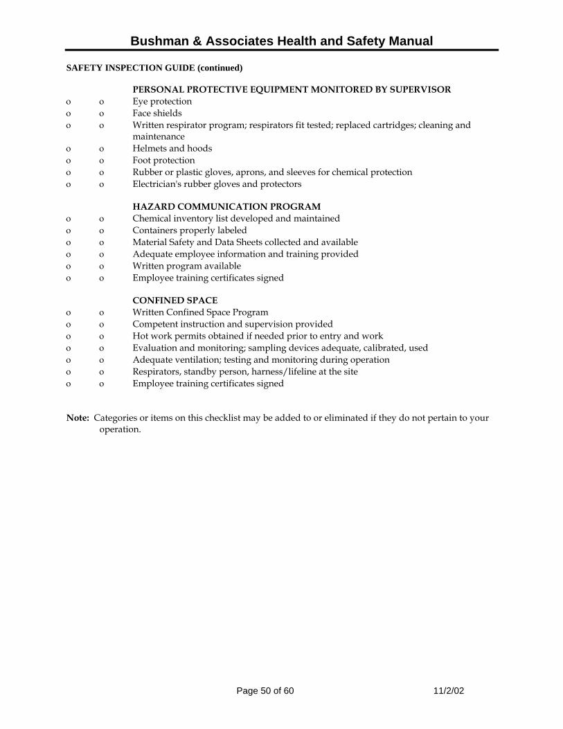
Bushman & Associates Health and Safety Manual
Page 50 of 60 11/2/02
SAFETY INSPECTION GUIDE (continued) PERSONAL PROTECTIVE EQUIPMENT MONITORED BY SUPERVISOR ο ο Eye protection ο ο Face shields ο ο Written respirator program; respirators fit tested; replaced cartridges; cleaning and
maintenance ο ο Helmets and hoods ο ο Foot protection ο ο Rubber or plastic gloves, aprons, and sleeves for chemical protection ο ο Electrician's rubber gloves and protectors HAZARD COMMUNICATION PROGRAM ο ο Chemical inventory list developed and maintained ο ο Containers properly labeled ο ο Material Safety and Data Sheets collected and available ο ο Adequate employee information and training provided ο ο Written program available ο ο Employee training certificates signed CONFINED SPACE ο ο Written Confined Space Program ο ο Competent instruction and supervision provided ο ο Hot work permits obtained if needed prior to entry and work ο ο Evaluation and monitoring; sampling devices adequate, calibrated, used ο ο Adequate ventilation; testing and monitoring during operation ο ο Respirators, standby person, harness/lifeline at the site ο ο Employee training certificates signed Note: Categories or items on this checklist may be added to or eliminated if they do not pertain to your
operation.

Bushman & Associates Health and Safety Manual
Page 51 of 60 11/2/02
BAROMETER OF SAFETY ATTITUDES CONSTRUCTION SELF INSPECTION GUIDE
ο Power lines: Minimum 10' clearance / insulate – de-energize, under 50 kw; over 50 kw.
ο Trench/excavation: Any trench four feet or more must be sloped, shored or braced.
ο Guardrails: Any opening four feet or more above ground level must be guarded.
ο Standard guardrail: Top rail = 36" - 42" above working surface, Mid rail = 18" - 22" with toe board
ο Scaffold/guardrail: Fully planked
ο Flights of stairs: Four or more risers must have handrails
ο Fall protection: Any exposure to the hazard of falling from elevations 6' or greater must be eliminated by the use of safety harness/belt, lanyard or lifeline, horizontal lines, or centenary lines. Positive fall protection must be used at all times.
ο Open belts and pulleys, chains and sprockets and points of operation must be guarded to prevent accidental contact. Air compressors and electric motor pulleys are most common hazards.
ο Radial saws: Cutting head must return easily to start position when released; blade must not extend past the edge of the work table; off/on switch should be at front of operator's position.
ο Table saws: Upper hood guard; anti-kickback, push stick, belt, pulley
ο Circular saws: Blade guard instantly returns to covering position
ο Never wedge or pin a guard
ο Chainsaw: Ballistic nylon leg protection; eye, ear, face protection; hard hat
ο Angle grinders; 180' guard required
ο Ladders: Extend 36" above landing and secure to prevent displacement
ο Articulating boom lift: Safety at all times
ο Floor holes/openings covered, secured; be sure no tripping hazards in area
ο Extension cords/electric power tools, marked/covered by Assured Grounding Program
ο Minimum of short sleeve shirts, long pants and substantial footwear - no recreation shoes
ο Hard hat readily accessible/worn when overhead hazards exist
ο Oxygen/acetylene storage areas chained and separated
ο Personal protective equipment: head, eye, ear respiratory, and leg protection, high visibility vests
ο Housekeeping: Workers responsible for own areas of exposure
ο First aid kit - Fire extinguishers
ο Minimum of one person at all times - first aid and CPR trained
ο Accident prevention program
ο Crew leader meetings: Meetings specifically tailored to each subcontractor ο Chemical hazard communication program
Bushman & Associates Health and Safety Manual
Page 52 of 60 11/2/02
EQUIPMENT SAFETY INSPECTION CHECKLIST
• This form is used as a checklist for equipment coming into a project. • The items to be checked are listed and are required to be checked as a minimum
pre-work inspection. • Any item that needs attention will be corrected before the equipment is put to work
on the project. • The report will be filed at the Field Office for the duration of the project. A copy will
also be sent to the main office. • These forms will be inspected by company safety personnel, as well as
governmental safety representatives. • The Project Manager is responsible for ensuring that the pre-operating safety check
is properly done.

Bushman & Associates Health and Safety Manual
Page 53 of 60 11/2/02
EQUIPMENT SAFETY INSPECTION CHECKLIST
Date:___________________________________________________________ Equipment Number/Name:_______________________________________ Project:__________________________________________________________ All guards and fenders ____________OK ______ Needs Repair Brakes ____________OK ______ Needs Repair Lights—Front, Rear, Side Dash ____________ OK ______ Needs Repair Bakup Alarm – Horn ____________ OK ______ Needs Repair Ladders / Stairs / Hand Holds ____________ OK ______ Needs Repair ROPS ____________ OK ______ Needs Repair Seat Belts ____________ OK ______ Needs Repair Fire Extinguisher ____________ OK ______ Needs Repair Glass ____________ OK ______ Needs Repair Tires ____________ OK ______ Needs Repair Other Items Checked: Oil – Level & Leaks _______ OK ______ Needs Repair _____Add _____Change Antifreez – Level
& Leaks _______ OK ______ Needs Repair _____Add _____Change Fuel – Level & Leaks_______ OK ______ Needs Repair _____Add _____Change Hydraulic Oil Level & Leaks ________ OK _______ Needs Repair _____Add _____Change First Aid Kit ________ OK _______ Needs Repairs _____Add _____Change Checked By:__________________________________________________________________ Date Repaired By:__________________________________________________________________
Date

Bushman & Associates Health and Safety Manual
Page 54 of 60 11/2/02
JOB SAFETY ANALYSIS WORKSHEET
TITLE OF JOB OPERATION________________________________________Date_______________
Position/Tile of person who does job ______________________________________________ Employee Observed ________________________Location____________________________ Analysis made by _______________________Analysis approved by_____________________ Sequence of basic job steps Potential accidents or hazards Recommended safe job procedure Personal protective equipment required:

Bushman & Associates Health and Safety Manual
Page 55 of 60 11/2/02
FALL PROTECTION WORK PLAN
SITE SPECIFIC
Job Name ______________________ Date Prepared ________________________ Person approving plan ____________________ Title Job Superintendent Activities: Inspection and coordination of work performed or being performed. Identify hazards in the work area: Uneven surfaces, debris, holes, overhead structural members, electrical, piping, and/or other installed systems. Check methods of fall restraint or arrest to be used: ___ Standard guardrail ___ Double lanyard system ___ Safety net(s) top, middle & toe board ___ Full body harness ___ Float ___ Horizontal lifeline ___ Tie off point capable ___ Restraint line ___ Secured to existing strut of 5,000 lb. load ___ Beam seat ___ Shock absorber lanyard ___ Retractable lanyard ___ Scissor lift ___ Drop line-rope grab ___ Scaffold-with guardrail and toe boards ___ Boom lift ___ Other (specify) Lanyard Describe procedures for assembly, maintenance, inspection and disassembly system (attach separate sheet if more space is needed). Describe procedures for handling and securing tools and equipment, and providing overhead protection for employees (attach separate sheet if more space is needed).

Bushman & Associates Health and Safety Manual
Page 56 of 60 11/2/02
FALL PROTECTION WORK PLAN
SITE SPECIFIC (continued)
Describe method for prompt, safe removal of an injured employee(s). Provide stick drawings of system configuration I certify that I received fall protection orientation including the material covered in this plan. Employee(s) signature and date: ___________________________________________ ________________________ ___________________________________________ ________________________ ___________________________________________ ________________________ ___________________________________________ ________________________ This plan has been prepared as a general guideline. Site Safety Officers Depending on the Phase of the Job, one of the following persons on-site will be the Safety Officer for Bushman & Associates:
– Mr. James B. Bushman, President, Bushman & Associates, Inc. – Mr. N. Dennis Burke, President, Burke & Associates, Inc. – Mr. William P. Carlson, President, Cathodic Protection Management, Inc.
In the absence of the following three (3) individuals, the current senior manager for Bushman & Associates or their Prime Subcontractor for that phase of work will be the designated Safety Officer:
Bushman & Associates Health and Safety Manual
Page 57 of 60 11/2/02
– Fall Protection Work Plan Overview
Job Name: ____________________________________ Date: _______________ Site Address: __________________________________ Fall Hazards Type of Fall Protection Specific Location Structural Steel Connection ____________________ _____________________ Bolting ____________________ _____________________ Decking ____________________ _____________________ Welding ____________________ _____________________ Acetylene Burning ____________________ _____________________ Crane Supported Platforms ____________________ _____________________ Boom Lift ____________________ _____________________ Scissor Lift ____________________ _____________________ Perimeter ____________________ _____________________ Roof ____________________ _____________________ Stairwells ____________________ _____________________ Ladders ____________________ _____________________ Scaffolds over 10 feet ____________________ _____________________ Rolling Scaffolds ____________________ _____________________ Exterior Scaffolds ____________________ _____________________ Elevator Shafts ____________________ _____________________ Wall Openings ____________________ _____________________ Upper Floor material ____________________ _____________________ Loading/unloading area ____________________ _____________________
Check Fall Protection to be used A – Standard guardrail G – Double lanyard system L – Safety net(s) Top, middle & toe board H – Full body harness M – Float B – Horizontal lifeline I - Tie off point capable N – Restraint line C – Secured to existing strut of 5,000 lb. Load O – Beam seat D – Shock absorber lanyard J – Retractable lanyard P – Scissor lift E – Drop line – rope grab K – Scaffold w/guardrail Q – Other F – Boom lift

Bushman & Associates Health and Safety Manual
Page 58 of 60 11/2/02
Fall Protection Work Plan Overview (continued)
Daily Inspection A visual inspection of all safety equipment shall be done daily or prior to each use. Defective equipment is to be tagged and removed from use immediately. The manufactures’ recommendations for maintenance, inspection and for assemble and disassembly of equipment must be followed. Overhead Protection Hardhats are required on all job sites and shall be worn. Warning signs, barricades and/or warning tape must be used to caution workers of existing hazards whenever present. Floor openings must be covered with wood or metal. In some cases debris nets or covered walkways may be used if the hazards warrant additional protection. Tools and Materials Equipment is to be stored in tool shed or some other means of lock and key area each night and handed out daily, as needed. Power tools and cords shall be unplugged and locked up at night. Ladders may be secured to the existing structures when conditions impose a hazard. All materials are to be stored in a neat and orderly manner to avoid causing hazards blocking access and egress. All materials and equipment must be secured to restrict mobility from adverse weather conditions. Removal of an injured worker First aid procedures should be performed as the situation requires. If the area is safe for entry first aid procedures should be started. Summon additional help, as needed, ambulance, fire or medical aid.
Dial 9-1-1
Telephone Location ____________________________ Job Site Address ____________________________ First Aid Kit Location ____________________________ Training and Instruction Program All new employees are given instruction on the proper use and care of fall-protection devices before they begin work and must sign a training form stating that they have received this training. This site-specific fall-protection program will be reviewed before work begins on the job site. The employee’s attendance record will be signed and fall protection equipment use will be reviewed on a regular basis.
SIGNED OFF BY: ______________________________________ (Project Supervisor) DATE: __________________________

Bushman & Associates Health and Safety Manual
Page 59 of 60 11/2/02
Southwestern Medical Center (580) 531-4755 (580) 531-4700 (580) 531-4976 (580) 531-4756 5602 SW Lee Blvd Lawton, OK 73505
Start address: Fort Sill, OK 73503
End address:
Southwestern Medical Center 5602 SW Lee Blvd Lawton, OK 73505
Distance: 11.2 mi (about 19 mins) Reverse directions 1. Head north from Condon Rd - go 0.4 mi 2. Turn right at Sheridan Rd - go 0.8 mi
3. Bear right into the I-44 W entry ramp - go 4.7 mi
4. Take the OK-7 W exit 36B - go 0.4 mi 5. Bear right at OK-7 W - go 0.5 mi 6. Continue on OK-7 W - go 1.8 mi 7. Continue on SW Lee Blvd - go 2.4 mi 8. Make a U-turn at SW Lee Blvd - go 0.2 mi

Bushman & Associates Health and Safety Manual
Page 60 of 60 11/2/02
Google Maps · from: Fon Si ll, Oklahoma to: 5602 SW l ee Blvd, lawto .. hllp :llwww.google.c01l1/maps·! l i= lmd&h l=~n&q=hospita l+loc:+lawton ...
I of I
Directions Start address Fort Sill, Oklahoma
End address 5602 SW lee Blvd, Lawton, OK 73505 (Southwestern Medical Center)
•
Slart address: Fort Sill , OK 73503
End address: Southwestern Medical Center 5602 SW Lee Blvd l awton, OK 73505
Dislance: 11.2 mi (about 19 mins)
1. Head north from Condon Rd • go 0.4 mi
2. Turn right at Sheridan Rd - go 0.8 mi
3. Bear right into the 1-44 W entry ramp - go 4.7 mi
4. Take lhe OK·7 W exit 36B - go 0.4 mi
5. Bear right at OK-7 W . go 0.5 mi
6. Conlinue on OK·7 W · go 1.8 mi
7. Conlinue on SW lee Blvd · go 2.4 mi
8. Make a U·turn at SW lee Blvd - go 0.2 mi
h«IIJ tWlI 01005 NAVTEQ"· . TeIc..At~
These directions are for planning purposes only. You may find that construction projects, traffic , or other events may cause road condition! differ from the map results
Map data Cl2005 NAVTEO "' , Tele AileS
91512005 11 :42 PM

BUSHMAN & Associates, Inc.
C O R R O S I O N C O N S U L T A N T S
P.O. Box 425, Medina, OH 44258 Phone 330/769-3694, Fax 330/769-2197
B&A Communications Plan – Ver. 2.0
AR-F-322- Cathodic Protection of Hot Water Tanks at Ft. Sill, OK
1.0 Background: The objective is to implement impressed current cathodic protection systems using ceramic anodes for six (6) large hot water storage tanks at Ft. Sill. The following is Bushman & Associates’ (B&A) communications plan for this project
Primary Corps of Engineers (COE) Contacts:
USACE Ft. Sill Resident Office – Mr. James E. Snyder -- (580) 355-6148 x40 – Initial Point of Contact (POC) for each on-site project phase. Also POC for minor technical issue with respect contract execution; Alternate POC -- Matt Ellis -- 719-570-7797 COE Construction Engineering Research Laboratory (CERL) – Dr. L. D. Stephenson -- 800-USA-CERL – Contract Final Technical Authority; Alternate POC – Dr. A. Kumar; 800-USA-CERL COE Tulsa Office – Mr. Jeff Waldie – 918-669-7044
Primary Fort Sill Contacts:
DPW Utilities – Mr. Jerry Schmidt, Mechanical Engineer, (580) 442-4219 DPW Utilities – Mr. Ahmad Santina, Corrosion Engineer including Cathodic Protection, (580) 442-6026 Fort Sill Fire Prevention – Ms. Helen Landry – (580)-442-5911 – For all Fire Prevention issues including welding safety procedures and clearances.
Contract & Purchasing Contact:
Mr. Charles Gibbs, S&K Technologies, Inc. -- (478) 971-673 – For all Contract Changes and Questions and all Billing and Invoicing Items
B&A Communications Plan Page 1 of 2 AR-F-322- ICCP Hot Water Tanks

B&A Communications Plan Page 2 of 2 AR-F-322- ICCP Hot Water Tanks
Prime Contractor contact:
James B. Bushman, Project Administrator and President Bushman & Associates, Inc. – for all contract, engineering, billing and general
operation issues – Final Prime Contractor Authority Mailing Address:
PO Box 425 Medina, OH 44258
Shipping Address:
6395 Kennard Road Medina, OH 44256
Phone Office: 330-769-3694 Phone Cell: 330-310-9099 Fax: 330-769-2197 Email: [email protected] Web: www.bushman.cc
Prime Subcontractor Contact:
William Carlson, Project Manager and Corrosion Consultant (sub-contractor to B&A) – For all remote monitoring and ICCP deep anode system installation issues Cathodic Protection Management, Inc. PO Box 95665 Hoffman Estates, IL 60195
Phone Office: (847) 885-7777 Phone Cell: (224) 588-6760 Fax: (847) 885-4593 Email: [email protected]

ERDC/CERL TR-07-26 B1
Appendix B: Rectifier Manual and Electric Schematic

VARIABLE TRANSFORMER TYPE CATHODIC PROTECTION RECTIFIER
INSTALLATION, OPERATION, & MAINTENANCE MANUAL
INTEGRATED RECTIFIER TECHNOLOGIES, INC. 15360 - 116 Avenue, Edmonton, Alberta, Canada T5M 3Z6
Phone: (780) 447-1114 Fax: (780) 454-0004 Website: ww"",jrt~~ctiflercQrl} Email: §..§[email protected]

VARIABLE TRANSFORMER TYPE CATHODIC PROTECTION RECTIFIER MANUAL INTEGRATED RECTIFIER TECHNOLOGIES, INC.
INDEX
PAGE
INTRODUCTION 3
DELIVERY INSPECTION 3
PRE-INSTALLATION STORAGE 4
SAFETY PRACTICES 4
GENERAL INSTALLATION TIPS 5
AC & DC CONNECTION 6
GENERAL COMPONENT DESCRIPTION 6
INITIAL ENERGIZATION 7
REGULAR MAINTENANCE AND ADJUSTMENT 9
TROUBLESHOOTING 11
APPENDIX:
INCLUDES ELECTRICAL SCHEMATIC, RECTIFIER DATA SHEET, AND ANY OTHER OPTIONAL INFORMATION
Doc #: VAR0010 Rev. 0.0
Page 2 of 15

VARIABLE TRANSFORMER TYPE CATHODIC PROTECTION RECTIFIER MANUAL INTEGRATED RECTIFIER TECHNOLOGIES, INC.
should then be accepted, and a claim filed with the freight carrier. Please ensure to retain the original packaging that may indicate how the damage occurred.
If damage has occurred during shipment and repairs or a return to the factory is required, please contact us, or your local IRT distributor, with the Serial Number and the Model Number of the rectifier. This information is crucial for us to determine the rectifier unit in question and to be able to provide suitable assistance. An RMA number must be obtained from the factory prior to return of any damaged rectifier units.
PRE-INSTALLATION STORAGE
If the rectifier unit is to be stored prior to installation, it is recommended that it be stored in a dry area, preferably indoors. If the unit is to be stored outdoors for an extended period of time, it is recommended that it be placed on a raised surface (pallet or platform) and covered with a protective sheet or tarp to ensure the packaging does not deteriorate due to rain or snow. Whether stored indoors or outdoors, the unit should be placed in an area where it is protected from accidental damage from moving vehicles or equipment. Ensure that the rectifier unit is transferred to and from the storage facility using proper handling techniques.
SAFETY PRACTICES
As Cathodic Protection rectifiers are connected to the AC utility power, electrical shock hazards are present within the rectifier units. It is recommended that only qualified electronic or electrical personnel operate and maintain these units and that those personnel familiarize themselves with the areas of possible hazard within the unit. Following these practices can enhance the safety of personnel.
1.) Prior to site maintenance or inspection, familiarize yourself with the rectifier and conditions at the site.
2.) Prior to doing any maintenance or troubleshooting on a rectifier unit, familiarize yourself with any possible hazard points within the unit by reviewing the electrical schematic and the physical layout of the rectifier.
3.) Whenever possible, set the AC disconnect from the power utility to the "OFF" position prior to starting any work on the rectifier unit. Even with the rectifier AC input circuit breaker in the "OFF" position, hazardous voltages are still present at any terminals connected to the rectifier AC input terminals. Always tag and lock out the disconnect to ensure others do not energize it while you are completing the rectifier work.
4.) Prior to opening the rectifier enclosure door, lightly touch the back of your hand to the enclosure latch. If you feel an electrical tingle, set the fused AC disconnect to the "OFF" position and contact an electrician for assistance.
Doc #: VAR0010 Rev. 0.0
Page 4 of 15

VARIABLE TRANSFORMER TYPE CATHODIC PROTECTION RECTIFIER MANUAL INTEGRATED RECTIFIER TECHNOLOGIES, INC.
AC & DC CONNECTION
After the rectifier has been installed in a suitable location, have a qualified electrician connect the rectifier unit to the AC supply following local and national codes. Please note that most electrical codes require a disconnect device between the AC power supply and the rectifier. For AC input voltages other than 115 VAC, (230, 115/230 VAC), refer to the Electrical Schematic for proper configuration of the AC input terminals and jumpers based on the actual AC input voltage being supplied and that the AC input wires are connected to the correct AC input terminals.
A grounding rod or rods should be installed as close as possible to the rectifier location but not too close to the AC input or DC output cables. The grounding rod(s) should be connected to the ground lug terminal adjacent to the AC input terminals within the rectifier.
Next, connect the cable(s) from the anode bed to the rectifier positive output lug terminal(s) and the structure cable(s) to the rectifier's negative output lug terminal(s). Ensure that these cables are suitably sized for the expected current and the length of the cable run. Also, it is absolutely imperative that the polarity of DC connections is correct. A reversal of the DC cables can actually cause accelerated corrosion and eventually, severe damage to the structure to be protected.
GENERAL COMPONENT DESCRIPTION
When operating any equipment, it is a good practice to become familiar with the key components and the general operation of that piece of equipment. The key components of a rectifier and their function are described below:
The AC Input Surge Arrestor is a device that protects the rectifier components from voltage surges that may occur across the AC input of the rectifier. It does this by providing a bypass circuit for the resultant current from these high voltage surges after a specific voltage threshold has been reached. Most surge arrestors are designed to handle a certain number or energy value of surges prior to failing. Depending upon the option ordered, this device may be a high capacity arrestor, or a Metal Oxide Varistor disk.
The rectifier AC Input Circuit Breaker (CB 1) is a fully magnetic type that serves three key functions. It is used as an "OFF-ON" switch for the rectifier, it provides "short circuit" protection, and, to a lesser degree, provides input overload protection.
The rectifier Main Transformer (T1) provides full electrical isolation between the utility AC power and the Cathodic Protection DC circuit. It also steps the voltage up or down as required for the DC circuit.
The Variable Transformer (VT1) provides the means for the DC output adjustment. The variable transformer is essentially "tap less" and provides for a very fine adjustment of the rectifier output voltage. Rectifier output adjustment may be done energized and under load.
Doc #: VAR0010 Rev. 0.0
Page 6 of 15

VARIABLE TRANSFORMER TYPE CATHODIC PROTECTION RECTIFIER MANUAL INTEGRATED RECTIFIER TECHNOLOGIES, INC.
the panel meters (this deflection may be quite minimal). For units with a metering switch, ensure to set the switch to the "ON" position. Next, adjust the variable transformer to a slightly higher output setting. A setting on the control knob to a 20-25% setting on the dial is usually adequate. Set the circuit breaker to the "ON" position and verify the metering has deflected to a suitable value. If either meter deflects fully to the right, immediately adjust the variable transformer of the rectifier to a lower output setting. Also, verify that the DC voltage and current shown on the metering is as expected for the subject output circuit (i.e. structureto-anode bed resistance). If no problems are evident, the rectifier can be adjusted to the "target" current required to provide a sufficient cathodic protection potential on the output structure. The rectifier may be adjusted without setting the rectifier circuit breaker to the "OFF" position.
After the "target" current has been achieved, verify the rectifier metering is showing accurate readings by comparing them to readings taken with an external Digital Volt Meter (DVM). The rectifier on-board voltmeter can be verified by simply measuring the DC voltage across the rectifier DC output lug terminals with the DVM. The rectifier on-board ammeter can be verified by measuring the voltage (in millivolts) across the calibrated test screws of the rectifier shunt (not across the connection bolts). To determine the current through the shunt from the millivolt reading taken, the following formula can be used:
DC Current (I) = Measured Shunt Voltage (millivolts) X Rated Shunt Current Rated Shunt Voltage (50 millivolts typical)
Note: Rated shunt current and voltage values are stamped onto the body of the shunt and are also shown on the rectifier data page.
The ammeter can also be verified with an external DC clamp-on type meter, if available.
It is also useful to check the conversion efficiency percentage of the rectifier, which is defined as:
Conversion Efficiency (%) = DC Output Voltage X DC Output Amperage X 100% AC Input Wattage
The AC input wattage can be obtained by connecting an AC Wattmeter to the AC input of the rectifier. The expected conversion efficiency for a single-phase rectifier with a full-wave silicon diode bridge is approximately 70-75%. For a three-phase rectifier, the expected efficiency would be approximately 90-95%. If the efficiency of the rectifier is significantly lower than these values, this may be an indication of a damaged diode bridge (refer to the "Troubleshooting" section).
It is recommended that all initial energization readings be recorded for future reference. Useful readings to record are structure potential levels prior to energization, AC input voltage & current, DC output voltage and current, tap or adjustment dial setting, conversion efficiency, structure potential levels after energization, as well as any observed problems or possible future concerns with the installation, in general.
Doc #: VAR0010 Rev. 0.0
Page 8 of 15
VARIABLE TRANSFORMER TYPE CATHODIC PROTECTION RECTIFIER MANUAL INTEGRATED RECTIFIER TECHNOLOGIES, INC.
Prior to any adjustment of the rectifier, measure and record the "As Found" readings of the rectifier (DC voltage, DC amperage, etc.). Next, set the rectifier circuit breaker and the utility disconnect to the "OFF" position to allow for a detailed rectifier inspection.
CAUTION: Please ensure that the utility disconnect is in the "OFF" position prior to any internal rectifier maintenance as hazardous voltages are still present within the rectifier even with the rectifier circuit breaker in the "OFF" position.
At least once a year the rectifier should be inspected for loose electrical connections that could eventually cause damage to the electrical panel, wiring, or rectifier components. If an electrical connection becomes loose, the resistance of the connection increases and causes it to heat up. This additional heat will cause the connection to oxidize and become even higher resistant until a failure occurs. The best way to check for a heated connection is with a temperature probe, however, as these are not typically standard issue for Cathodic field maintenance, the visual inspection method will suffice. First, visually inspect all of the main electrical connections within the rectifier for signs of discoloration on the connection terminal, the electrical panel, or the wire attached to the terminal. Key points to check are the DC output lug terminal connections and the fuse holder connections. If you see a suspect connection, use a wrench or other suitable tools to see if the connection is indeed loose. (Note: Be careful when touching these types of connections with your hand as the temperature of loose high current connections can cause a significant burn.) If you do find a loose connection, it should be secured with suitable tools (ensure to secure both the front and rear of panel connections). If a loose connection has already caused damage to the electrical panel, the panel should be repaired or replaced, as re-tightening a connection on a degraded panel will most likely still lead to a future failure.
Certain main components within the rectifier should also be inspected for signs of overheating or other damage.
The main isolation transformer (T1) within the rectifier is designed to operate at a fairly high temperature and thus is usually somewhat discoloured. However, it should not be extremely dark or black. If it is, this could indicate insufficient I blocked venting or a problem within the transformer itself.
The variable transformer (VT1) should be checked for any signs of overheating, and for any oxidation of the brush wiper surface. A typical failure condition of a variable transformer is the discoloration or burning of a single turn of the transformer's winding. Check for excessive wear on the wiper arm brush.
The AC primary, AC secondary, and the DC output surge arrestors should be checked to ensure that a significant voltage surge has not damaged them. Signs of damage to an arrestor device are usually visually noticeable by a blackened or cracked housing. Please note however that sometimes the operational status of an arrestor is not discernable visually and requires further checking (see Troubleshooting section).
The rectifier fusing should also be checked for overheating. If the fusing is a bolt-on type (for larger rectifier units), ensure that the fastening studs or bolts are secure on both the front and
Doc #: VAR0010 Rev. 0.0
Page 10 of 15

VARIABLE TRANSFORMER TYPE CATHODIC PROTECTION RECTIFIER MANUAL INTEGRATED RECTIFIER TECHNOLOGIES, INC.
1.) If there is no reading on the rectifier ammeter, make sure to check that there is not a metering switch which must be activated to get a reading on the meter. If there isn't a metering switch or if the metering switch is activated and there still is no current showing on the meter, the operational status of the ammeter should be verified. This can be done by measuring the DC voltage across the calibrated test screws of the rectifier shunt or by using an external DC clamp-on type meter, if available. If the shunt measurement or clamp-on indicates that there is no current, continue to the next step. If the measurement indicates that there is current, there is either a problem with the ammeter, the ammeter connection or, if supplied, the ammeter switch. With power to the rectifier "OFF", trace the ammeter wires from the shunt to the meter itself. Use a Digital Volt Meter (DVM) on the resistance or diode check setting to determine if the wires are continuous from the shunt terminals to the meter terminals. If the DVM reads a high resistance, the subject wire or the crimp connection has gone high resistant and should either be repaired or replaced. If there is an ammeter switch, ensure to activate it during this test. If the DVM still shows a high resistance even after the ammeter switch is activated, the switch has most likely failed and should be replaced. If the wire connections and the ammeter switch are continuous, the ammeter has most likely failed and should be replaced.
2.) If there is no DC output current from the rectifier, as verified in the above step, but there is DC output voltage, verify that the DC output connections are secure and that the DC output cabling is continuous. A common misconception is that if there is DC voltage at the rectifier output terminals but no DC current, that there is a problem with the rectifier. This is incorrect. If there is DC voltage at the rectifier output terminals but no DC current, it is almost guaranteed that the DC output cabling to either the structure or the anode bed is discontinuous. As per Ohm's Law, if the circuit resistance is infinitely high, the current will be infinitely low. To verify this, a temporary load resistor could be connected across the DC output terminals of the rectifier. If there is now DC output current, there is a problem with the DC output circuit or cabling.
3.) If there is no reading on the rectifier voltmeter, ensure to check that there is not a metering switch that must be activated to get a reading on the meter. If there isn't a metering switch or if the metering switch is activated and there still is no voltage showing on the meter, the operational status of the voltmeter should be verified by measuring the DC voltage across the DC output terminals of the rectifier. If the measurement indicates that there is no voltage, continue to the next step. If the measurement indicates that there is a DC voltage, there is either a problem with the voltmeter, the voltmeter connection or, if supplied, the voltmeter switch. Follow the steps outlined in Step 1 above to determine where the fault lies.
4.) If it is found that there is no output voltage or current from the rectifier, there are five key areas to check:
a. Check the continuity of the AC secondary fusing (or DC output fusing, if supplied) by setting the DVM to the resistance or diode check mode and measure across the fuse(s). If a high resistance is measured, the fuse has opened and should be replaced (prior to replacement see Step 5). If a very low resistance is measured, the fuse is operational and other components should be checked.
Doc#: VAR0010 Rev. 0.0
Page 12 of 15

VARIABLE TRANSFORMER TYPE CATHODIC PROTECTION RECTIFIER MANUAL INTEGRATED RECTIFIER TECHNOLOGIES, INC.
As long as the DC surge arrestor doesn't fail in a shorted condition (zero resistance), the fuse can simply be replaced and the rectifier should operate properly. However, if the DC surge arrestor does fail in a shorted condition, any replacement fuses installed will continue to fail immediately. To determine if the DC output arrestor has shorted, disconnect the DC output cables from the rectifier and measure across the rectifier DC output terminals with a Digital Volt Meter (DVM) on the resistance or diode check setting. If a very low resistance is measured, the arrestor has probably failed. Remove the arrestor from the circuit, re-check it, and replace as necessary.
c. The AC secondary fuse may also fail if one or more of the diodes in the diode bridge assembly have shorted. To determine if this is the cause, the following diode bridge verification procedure should be followed.
I. With the AC power "OFF", disconnect one of the two wires from the AC input of the diode bridge (BAC1). The output cables should also be disconnected from the rectifier DC output lug terminals.
II. With the DVM set on the diode check range, place the positive (Red) meter lead on the bridge negative terminal (BDC-) and touch the negative (Black) meter lead to each of the bridge AC input terminals. An operational diode should measure approximately 0.4 to 0.6 volts on the diode check setting and the DVM may emit a single beep. An open or short circuit reading will indicate a faulty diode that requires replacement.
iii. Next, place the negative meter lead on the bridge positive terminal (BDC+) and touch the positive (Red) meter lead to each of the bridge A.C. terminals. Similarly, an operational diode should measure approximately 0.4 to 0.6 volts on the diode check setting and the DVM may emit a single beep. An open or short circuit reading will indicate a faulty diode that requires replacement.
IV. When replacing the damaged diodes or diode modules, ensure to replace them the same type, voltage and polarity (for stud-mounted devices). Consult the rectifier data sheet or the factory for details. When installing stud type diodes, do not over-tighten them as the mounting studs may be easily damaged.
v. A final check to complete on the diode bridge assembly is to determine if any of the components are shorted to a grounding point. With the DVM again set on the diode check range, attach the negative (Black) meter lead to the rectifier ground terminal or frame and touch each of the diodes and heatsinks with the positive (Red) meter lead. There should an infinite resistance reading on the meter. If the meter reads a low resistance or short, somewhere one of the diode bridge components or wires is contacting a grounding point and must be repaired.
Doc#: VAR0010 Rev. 0.0
Page 14 of 15

CURRENT MONITORING ALARM
INSTALLATION, OPERATION, & MAINTENANCE MANUAL
INTEGRATED RECTIFIER TECHNOLOGIES, INC. 15360 -116 Avenue, Edmonton, Alberta, Canada T5M 3Z6
Phone: (780) 447-1114 Fax: (780) 454-0004 Website: www.irtrectifier.com Email: [email protected]

CURRENT MONITORING ALARM MANUAL INTEGRATED RECTIFIER TECHNOLOGIES, INC.
INTRODUCTION
The Integrated Rectifier Technologies Inc. Current Monitoring Alarm is designed to monitor the DC output current of a Cathodic Protection Rectifier or other power supply that utilizes a 50 or 100 millivolt shunt resistor. The IRT Current Monitoring Alarm can be supplied with new rectifiers or easily installed into an existing rectifier. Equipped with easily adjustable "HIGH" or "LOW" alarm settings and on-board status lamps (LEDs), the Current Monitoring Alarm gives the Cathodic Protection system professional a very useful tool to keep track of rectifier output status.
SPECIFICATIONS
AC INPUT:
AC INPUT FUSING:
AC INPUT SENSING:
1/0 CONNECTION:
RELAY CONTACT RATING:
SET-POINT ADJUSTMENT:
ALARM STATUS (LOCAL):
ALARM STATUS (REMOTE):
PHYSICAL SIZE I MOUNTING:
OPERATING TEMPERATURE:
115 or 230 Volt AC, 50 I 60 Hertz, 1-Phase
0.125 Ampere, 250 Volt, 5 X 20 mm.
50 or 100 millivolt (typically from rectifier shunt)
Pin-Header Connector, 12 Position
5 Ampere, 250 Volt AC, Non-Inductive
Single-turn Potentiometer for "LOW" & "HIGH" Set-points
On-board LEOs (Light Emitting Diodes) YELLOW for "LOW" Current Range GREEN for "NORMAL" Current Range RED for "HIGH" Current Range
Option "a" - High Intensity Green LED Status Lamp, 12 Volt DC, 10 Candlepower, 100,000 Hour, typically mounted on the enclosure door (flashing configuration available)
Option "b" - Green and Red LED Status Lamps, 12 Volt DC, 100,000 Hour, typically mounted on enclosure door
Option "e" - Green Incandescent Status Lamp (Red optional), 115 Volt AC, 6,000 Hour, typically mounted on the enclosure roof
Option "d" - One Set of Relay Contacts, Form "C" (Normally Open-Common-Normally Closed), connected to a terminal strip for external connection
Option "e" - Two Sets of Relay Contacts, Form "C" (Normally Open-Common-Normally Closed), connected to a terminal strip for external connection
NOTE: Combinations of the above Remote Alarm Status configurations are available. Consult Factory.
4.00"(H) X 4.75"(W) X 0.95"(0),3.30" X 3.80" mounting centers
Doc #: MNL0100 Rev. 1.0
Page 2 of 4

CURRENT MONITORING ALARM MANUAL INTEGRATED RECTIFIER TECHNOLOGIES, INC.
INSTALLATION (NOTE: Skip this Section if Potential Alarm is factory installed)
When the IRT Current Monitoring Alarm (CMA) is supplied for field installation into a Cathodic Protection rectifier, the below steps should be followed to ensure proper operation of the alarm circuit.
1.) Ensure that there is sufficient space within the rectifier to mount the CMA unit. It should be mounted on a flat, non-conductive material (typically phenolic) and requires an open area of approximately 6" X 6". The CMA unit is affixed via four mounting screws with mounting centers as noted in the above Specifications section. If required, the CMA unit can be supplied pre-mounted onto a phenolic mounting plate sized for the intended rectifier. The CMA unit should be mounted within the rectifier such that the set-point potentiometers are easily accessible and on-board status lamps (LEOs) are visible.
2.) After the CMA unit has been mounted, make sure that it is configured for the AC input available within the rectifier. The AC input to the CMA unit is configured via three jumpers on the circuit board. If the AC input available is 115 VAC, the jumpers JP6 & JP7 should be in place and JP5 should be removed. If the AC input available is 230 VAC, the jumpers JP6 & JP7 should be removed and JP5 should be in place. For AC inputs other than 115 or 230 VAC, an optional transformer kit is required.
3.) For field installations, the CMA unit is supplied with approximately 4' of AC input wiring. When connecting the AC input to the CMA unit, the wire connected to Pin 1 of the CMA connector (typically white) should be connected to the Line 2 (or Neutral for 115 VAC) of the AC input. The wire connected to Pin 2 of the CMA connector (typically black) should be connected to the Line 1 of the AC input. Please note that the AC input wires of the CMA unit should be connected to the AC input supply after the circuit breaker of the rectifier. Refer to the sample electrical schematic supplied at the end of this manual for details. It is strongly recommended that the AC disconnect and the rectifier AC circuit breaker be set to the "OFF" position prior to this CMA electrical connection.
4.) Connect the current sensing wires, supplied with the CMA unit, to the rectifier shunt. The white I orange striped wire connected to Pin 3 of the CMA unit should be connected to the positive calibrated screw terminal of the rectifier shunt. The orange wire connected to Pin 4 of the CMA unit should be connected to the negative calibrated screw terminal of the rectifier shunt.
5.) If the CMA unit is supplied with an optional alarm status indicator such as a high intenSity LED lamp or remote relay contacts, please refer to the sample electrical schematic supplied at the end of this manual for connection details.
Doc #: MNL0100 Rev. 1.0
Page 3 of 4
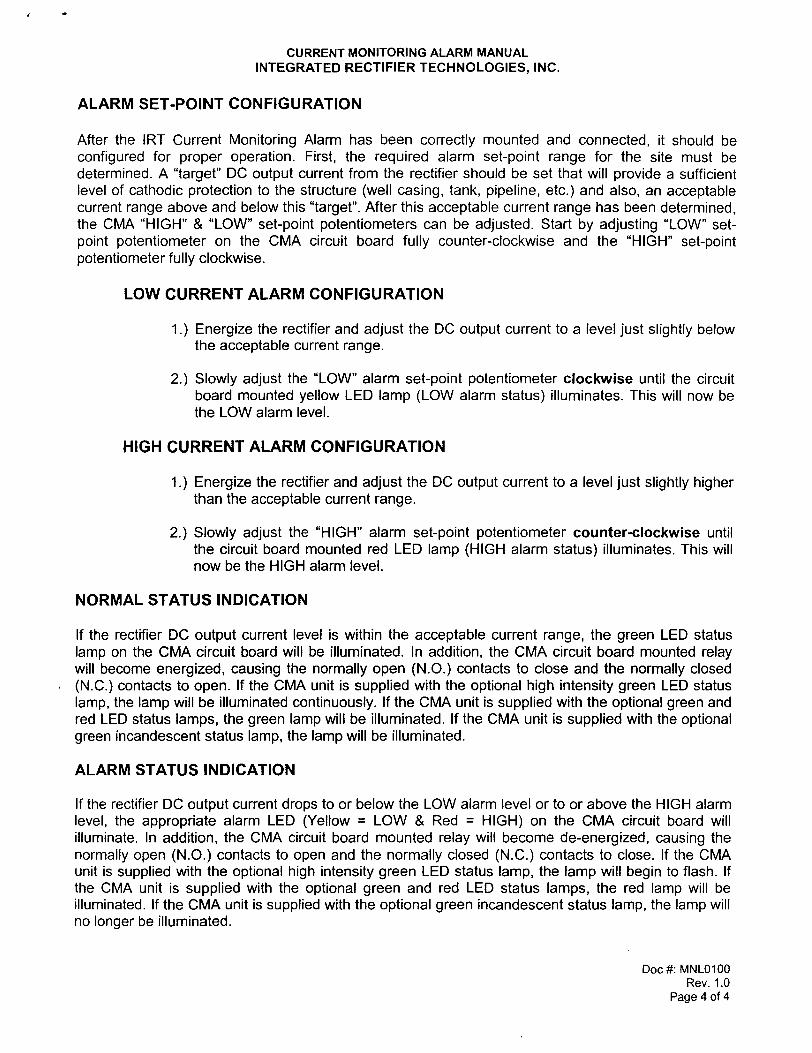
CURRENT MONITORING ALARM MANUAL INTEGRATED RECTIFIER TECHNOLOGIES, INC.
ALARM SET-POINT CONFIGURATION
After the IRT Current Monitoring Alarm has been correctly mounted and connected, it should be configured for proper operation. First, the required alarm set-point range for the site must be determined. A "target" DC output current from the rectifier should be set that will provide a sufficient level of cathodic protection to the structure (well casing, tank, pipeline, etc.) and also, an acceptable current range above and below this "target". After this acceptable current range has been determined, the CMA "HIGH" & "LOW" set-point potentiometers can be adjusted. Start by adjusting "LOW" setpoint potentiometer on the CMA circuit board fully counter-clockwise and the "HIGH" set-point potentiometer fully clockwise.
LOW CURRENT ALARM CONFIGURATION
1.} Energize the rectifier and adjust the DC output current to a level just slightly below the acceptable current range.
2.} Slowly adjust the "LOW" alarm set-point potentiometer clockwise until the circuit board mounted yellow LED lamp (LOW alarm status) illuminates. This will now be the LOW alarm level.
HIGH CURRENT ALARM CONFIGURATION
1.} Energize the rectifier and adjust the DC output current to a level just slightly higher than the acceptable current range.
2.} Slowly adjust the "HIGH" alarm set-point potentiometer counter-clockwise until the circuit board mounted red LED lamp (HIGH alarm status) illuminates. This will now be the HIGH alarm level.
NORMAL STATUS INDICATION
If the rectifier DC output current level is within the acceptable current range, the green LED status lamp on the CMA circuit board will be illuminated. In addition, the CMA circuit board mounted relay will become energized, causing the normally open (N.O.) contacts to close and the normally closed (N.C.) contacts to open. If the CMA unit is supplied with the optional high intensity green LED status lamp, the lamp will be illuminated continuously. If the CMA unit is supplied with the optional green and red LED status lamps, the green lamp will be illuminated. If the CMA unit is supplied with the optional green incandescent status lamp, the lamp will be illuminated.
ALARM STATUS INDICATION
If the rectifier DC output current drops to or below the LOW alarm level or to or above the HIGH alarm level, the appropriate alarm LED (Yellow = LOW & Red = HIGH) on the CMA circuit board will illuminate. In addition, the CMA circuit board mounted relay will become de-energized, causing the normally open (N.O.) contacts to open and the normally closed (N.C.) contacts to close. If the CMA unit is supplied with the optional high intensity green LED status lamp, the lamp will begin to flash. If the CMA unit is supplied with the optional green and red LED status lamps, the red lamp will be illuminated. If the CMA unit is supplied with the optional green incandescent status lamp, the lamp will no longer be illuminated.
Doc #: MNL0100 Rev. 1.0
Page 4 of 4

r 1 ~--------------------------------------------------------------------------
L1
AC !NPUT 115 VAC
NEUT.
GND
NOTES:
AC INPUT
TERMINALS
AC CIf,CUIT
BREAKER
TS1-A CBl
~ 8 ,-, '--' 1""-~ r-
~ M' AC INPUT
ARRESTOR
8:<
~ GROUND
INTERRUPT
ACCESS
TSl-8
8
VARIABLE
TRANSFORMER
VTl
1 3
4 4
21
22
1.) FOR COMPONENT DESCRIPTIONS, PART NUMBERS AND QUANTITIES, REVIEW THE RECTIFIER DATA SHEET.
MAIN
TRANSFORMER
T1
~ I~ 1 ~ \.
AC :

DIODE BRIDGE ASSEMBLY
BDC+ 0
D1 i iD2
F1
ECONDARY
FUSE MOV2
BRIDGE AC I/P
VARISTOR
BAC2
D3 ID4 j
0
BDC-
FAULT TS2
GREEN
EXTERNAL WHTiGRN STATUS LAMP::;
WHTiRED
STATUS LAMP
TERMINALS
ELAPSED TIME
HOUR COUNTER
DRAWN BY:
AS REV. DRAWING DATE:
11-09-05 REVIEWED BY:
REVIEW DATE:
IoIATERtAL;
N/A SCALE:
NTS
ANODE DC +
WHT!RED
R SCALE
(1K/V) DA1
DC OUTPUT ARRESTOR
VOLTMETER
AMMETER
RED
ORANGE WHT!ORG
DC SHUNT STRUCTURE
LED- MONITOR ALARM
[J LED+ LOW NORMAL HIGH N02
NC2 @ @ @ [J COM2 N01 STATUS LAMPS
[J NC1 [J COM1 SET-POINTS
IN- ~ ~ IN. AC1 LOW HIGH
A~FUSE (12SmA)
INSTALL JUMPER
REVISIONS DESCRIPTION OF REVISION
2,3,6 & 7
BY DATE 0~~ Integrated Rectifier ~~& Technologies, Inc.
TITll:
15360 -116 Avenue
Edmonton, Alberta, Canada T5M 3Z6
ELECTRICAL SCHEMATlC-115 VAC, 1-PH.,
VARIABLE TRANS. ADJUSTMENT, ALARM
WITH DUAL LAMPS AND COUNTER
SHEET NO,: DRAWING NO.: REV.:
1 of 1 M1-H1B121-AbMzQa A

ERDC/CERL TR-07-26 C1
Appendix C: ICCP System Replacement Parts List
Rectifier Units Provided for Fort Sill Hot Water Storage Tanks
Manufactured by: Integrated Rectifier Technologies, Inc., 15360 – 116 Avenue, Edmonton, Alberta T5M 3Z6, Phone: (780) 447-1114, Fax: (780) 454-0004
QTY. (6) MODEL ADASAS 50-12 AbMzQa ADVANTAGE RECTIFIERS
♦ 115 VAC, 60 Hz., 1-PHASE INPUT (Estimated maximum AC in-put current = 8.23 amperes).
♦ SUPPLIED WITH A SINGLE 50 VOLT – 12 AMPERE RATED, CONSTANT VOLTAGE, VARIABLE TRANSFORMER ADJUSTED DC OUTPUT CIRCUIT.
♦ “A-2” AIR-COOLED ENCLOSURE, CONFORMS TO A NEMA 3R RATING, 12 GAUGE MILL GALVANIZED STEEL FINISHED WITH 3-5 MILS OF WHITE FUSION BOND POWDER PAINT. EQUIPPED WITH (3) HINGED AND REMOVABLE DOORS. SUITABLE FOR WALL, POLE, OR FRAME MOUNTING.
♦ RECTIFIER CONSTRUCTED ON A SINGLE REMOVABLE FRAME ASSEMBLY.
♦ STANDARD FEATURES: HIGH ENERGY SURGE ARRESTORS ON THE AC INPUT & DC OUTPUT, FULLY MAGNETIC AC INPUT CIRCUIT BREAKER, HIGH SPEED FUSING IN THE TRANSFORMER SECONDARY (one spare of each fuse included), PROVISION FOR MANUAL VOLTAGE CONTROL VIA 25 STEPS (5-Coarse & 5-Fine) OF TAP LINK BAR ADJUSTMENT, AND SEPARATE, CONTINUOUS READING, AMMETER & VOLTMETER.
OPTIONS:
“Ab” - CURRENT MONITORING ALARM: SUPPLIED WITH (1) GREEN & (1) YELLOW STATUS LAMP (lamps shall be mounted on the enclosure front door). (The green lamp shall be illuminated when the DC output current
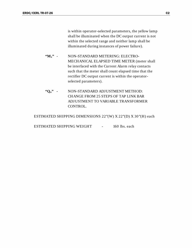
ERDC/CERL TR-07-26 C2
is within operator-selected parameters, the yellow lamp shall be illuminated when the DC output current is not within the selected range and neither lamp shall be illuminated during instances of power failure).
“Mz” - NON-STANDARD METERING: ELECTRO-MECHANICAL ELAPSED TIME METER (meter shall be interfaced with the Current Alarm relay contacts such that the meter shall count elapsed time that the rectifier DC output current is within the operator-selected parameters).
“Qa” - NON-STANDARD ADJUSTMENT METHOD: CHANGE FROM 25 STEPS OF TAP LINK BAR ADJUSTMENT TO VARIABLE TRANSFORMER CONTROL.
ESTIMATED SHIPPING DIMENSIONS 22”(W) X 22”(D) X 30”(H) each
ESTIMATED SHIPPING WEIGHT - 160 lbs. each

ERDC/CERL TR-07-26 D1
Appendix D: Recommended Future Monitoring Data Sheets
Start Up Data
Building No. 5960 Date: 4/26/2006 11/15/2006 12/15/2006 1/15/2007 2/15/2007 3/15/2007 4/15/2007 5/15/2007 6/15/2007 7/15/2007 8/15/2007 9/15/2007 10/15/2007
Tank No. 2 Hour Meter Reading:
Tank Dia. (inches) 52
Monitor Light (Greeen, Yellow or
None:
Tank Length (Inches) 144 Variac Set Point (0
to 100):
Rectifier Mfg. IRT DC Amps (Rectifier
Meter): 1.2
Rectifier Model No.
ADASAS 50-12 AbMzQa
DC Volts (Rectifier Meter): 5
Rectifier Serial No. 05R-1092 DC Amps (VOM
Meter): 4.84
Rated AC Volts 115 DC Volts (VOM
Meter): 1.7505
Rated AC Amps 8.23 ON Potential (-mV): 1.026
Rated DC Volts 50 INSTANT-OFF
Potential (-mV): 0.86
Rated DC Amps 12
Monthly Monitoring Data Sheet for Tank No. 1, Building 5960
Tank 2, Bldg. 5960 Rectifier DC Output (2006)
0
1
2
3
4
5
6
3/24/2006 7/2/2006 10/10/2006 1/18/2007 4/28/2007 8/6/2007 11/14/2007
Date
DC
Am
ps a
nd V
olts
AmperageVoltage

ERDC/CERL TR-07-26 D2
Start Up Data
Building No. 5970 Date: 4/26/2006 11/15/2006 12/15/2006 1/15/2007 2/15/2007 3/15/2007 4/15/2007 5/15/2007 6/15/2007 7/15/2007 8/15/2007 9/15/2007 10/15/2007
Tank No. 1 Hour Meter Reading:
Tank Dia. (inches) 48
Monitor Light (Greeen, Yellow or
None:
Tank Length (Inches) 170 Variac Set Point (0
to 100): 7
Rectifier Mfg. IRT DC Amps (Rectifier
Meter): 0.6
Rectifier Model No.
ADASAS 50-12 AbMzQa
DC Volts (Rectifier Meter): 4
Rectifier Serial No. 05R-1093 DC Amps (VOM
Meter): 0.561
Rated AC Volts 115 DC Volts (VOM
Meter): 3.63
Rated AC Amps 8.23 ON Potential (-mV): 0.884
Rated DC Volts 50 INSTANT-OFF
Potential (-mV): 0.846
Rated DC Amps 12
Monthly Monitoring Data Sheet for Tank 1, Bldg 5970
Tank 1, Bldg 5970 Rectifier DC Output (2006)
0
0.5
1
1.5
2
2.5
3
3.5
4
4.5
3/24/2006 7/2/2006 10/10/2006 1/18/2007 4/28/2007 8/6/2007 11/14/2007
Date
DC
Am
ps a
nd V
olts
AmperageVoltage
Start Up Data
Building No. 5970 Date: 4/26/2006 11/15/2006 12/15/2006 1/15/2007 2/15/2007 3/15/2007 4/15/2007 5/15/2007 6/15/2007 7/15/2007 8/15/2007 9/15/2007 10/15/2007
Tank No. 2 Hour Meter Reading:
Tank Dia. (inches) 48
Monitor Light (Greeen, Yellow or
None:
Tank Length (Inches) 170 Variac Set Point (0
to 100): 6
Rectifier Mfg. IRT DC Amps (Rectifier
Meter): 0.8
Rectifier Model No.
ADASAS 50-12 AbMzQa
DC Volts (Rectifier Meter): 7
Rectifier Serial No. 05R-1090 DC Amps (VOM
Meter): 0.714
Rated AC Volts 115 DC Volts (VOM
Meter): 6.462
Rated AC Amps 8.23 ON Potential (-mV): 0.827
Rated DC Volts 50 INSTANT-OFF
Potential (-mV): 0.746
Rated DC Amps 12
Monthly Monitoring Data Sheet for Tank No. 2, Building 5970
Tank 2, Bldg. 5970 Rectifier DC Output (2006)
0
1
2
3
4
5
6
7
8
3/24/2006 7/2/2006 10/10/2006 1/18/2007 4/28/2007 8/6/2007 11/14/2007
Date
DC
Am
ps a
nd V
olts
AmperageVoltage

ERDC/CERL TR-07-26 D3
Start Up Data
Building No. 6050 Date: 4/26/2006 11/15/2006 12/15/2006 1/15/2007 2/15/2007 3/15/2007 4/15/2007 5/15/2007 6/15/2007 7/15/2007 8/15/2007 9/15/2007 10/15/2007
Tank No. 1 Hour Meter Reading:
Tank Dia. (inches) 78
Monitor Light (Greeen, Yellow or
None:
Tank Length (Inches) 170 Variac Set Point (0
to 100):
Rectifier Mfg. IRT DC Amps (Rectifier
Meter): 1
Rectifier Model No.
ADASAS 50-12 AbMzQa
DC Volts (Rectifier Meter): 5
Rectifier Serial No. 05R-1088 DC Amps (VOM
Meter): 0.651
Rated AC Volts 115 DC Volts (VOM
Meter): 4.038
Rated AC Amps 8.23 ON Potential (-mV): 1.039
Rated DC Volts 50 INSTANT-OFF
Potential (-mV): 0.956
Rated DC Amps 12
Monthly Monitoring Data Sheet for Tank No. 1, Building 6050
Tank 1, Bldg 6050 Rectifier DC Output (2006)
0
1
2
3
4
5
6
3/24/2006 7/2/2006 10/10/2006 1/18/2007 4/28/2007 8/6/2007 11/14/2007
Date
DC
Am
ps a
nd V
olts
AmperageVoltage
ERDC/CERL TR-07-26 E1
Appendix E: Repair Visit Report
BUSHMAN & Associates, Inc.
C O R R O S I O N C O N S U L T A N T S
P.O. Box 425, Medina, OH 44258 Phone 330/769-3694, Fax 330/769-2197
Fort Sill – Hot Water Storage Tank Impressed Current Cathodic Protection System
Subject: July 22-23, 2006 Site Visit Report on Repairs to ICCP System in Bldg. 5955
Background: Bushman & Associates (B&A) designed and provided pro-ject management for the installation of impressed current cathodic protec-tion (CP) systems in six hot water storage tanks at Ft Sill, OK, in April 2006. When it was energized initially in April, the rectifier for tank in building 5955 exhibited an unusually output high current and a low volt-age compared to the other five tanks (ref tab labeled ICCP Initial Data -
April 2006 in Excel Workbook attached to this report). Over the months this anomaly remained. B&A made arrangements with the designated DPW personnel at Ft Sill to revisit the site to troubleshoot and repair the anomalous CP system in the building 5955 tank.
Summary of Site Visit Activities: The site vist was made on July 22-23, 2006 by William Carlson and George Smith of Cathodic Protection Man-agement (CPM) - B&A’s contractor on this project. The visit was hosted by Kim Shirley and Ahmad Santina (DPW); B&A was represented by Dr. Bopinder S. Phull.
July 22: The above personnel assembled at building 5955 at 18:15 hours. All work had to done after 8:00 pm on Saturday evening and had to be completed by early Sunday morning to minimize impact on the Army per-

ERDC/CERL TR-07-26 E2
sonnel housed in the building. The readings on the rectifier panel meters were recorded. In addition, the output voltage at the rectifier terminals, as well as the voltage-drop across the milliohm shunt resistance (to compute current), were measured using a Fluke-87 digital multimeter. This was fol-lowed by “ON” and “OFF” potential measurements for the tank, using a Cu/CuSO4 reference electrode and the multimeter. Then, with the rectifier off, resistance measurements were made using a Nilsson-400 resistivity meter. The data associated with all these measured are summarized in the attached spreadsheet (spreadsheet tab labeled 5955a Tank 1).
DPW personnel turned the water heating system off and started draining the tank at 19:30 hours. While the tank in building 5955 was draining (which took several hours), DPW personnel facilitated access to buildings 5960 and 6050 to allow rectifier voltage/current and tank ON/OFF poten-tial measurements to be made in those cases. The data obtained is in-cluded in the attached spreadsheet (tabs labeled 5960 Tank 1, 5960 Tank
2 and 6050 Tank 1). Lack of access to building 5970 precluded similar measurements there (Tabs labeled 5970 Tank 1 and 5970 Tank 2 provide space for inclusion of data that will be obtained by base personnel).
DPW personnel requested that the galvanized-steel conduits associated with CP of the tanks in buildings 5960 and 6050 be modified to make them more rigid. Carlson and Smith with B&A’s subcontractors for the ICCP system installation reduced the length of the galvanized-steel con-duit hanging vertically between the tanks in building 5960 – which also raised it by an additional ~ 12 inches above the valve in the waterline to mitigate this situation. No immediate modifications could be made to the conduit in building 6050 since access could not be obtained. Santina and Shirley (DPW) will review the situation.
After the tank had drained sufficiently, Carlson and Smith carefully re-moved the Conax fittings one at a time. Although the PTFE heat shrink sleeves appeared to “break” into smaller pieces, it was conjectured that this was just as likely the result of twisting action during the removal proc-ess of tight-fitting surfaces (see Figure 1).
The entire anode assembly was removed and new (~ 14 inch) PTFE sleeves were shrunk on to the anode ends using an electric heat gun (see Figure 2). This process took longer than expected. It sub-contractor indicated this was most probably due to the fact that the new shrink sleeves were notably

ERDC/CERL TR-07-26 E3
heavier wall than the original material. During the original installation, although heavier wall sleeves had been used on some anodes, however, a “hotter” propane had apparently been used in those cases instead of the electric gun. Preheating the anode material, using the electric gun, before sliding the PTFE sleeve for shrinking was helpful.
Once the sleeves were shrunk onto the anode ends, the anode was rein-stalled carefully in the tank. Electrical continuity check between the in-stalled anode and tank indicated open circuit; i.e. the anode was electri-cally isolated from the tank as required by the design. The tank was refilled with cold water. Results of the resistance measurements (using the Nils-son-400 meter) are summarized in the attached spreadsheet (spreadsheet tab labeled 5955a Tank 1). The free-corrosion potential of the tank was measured as -0.524 volts vs. Cu/CuSO4. The rectifier was energized to ob-tain the “ON” potential measurement (-1.047 volts vs Cu/CuSO4; and then briefly interrupted to obtain the “Instant-Off” potential measurement (-0.852 volts vs Cu/CuSO4). It was noted that the output current was mark-edly lower than before and the voltage was higher. This indicated that the installation of new PTFE sleeves on the anode ends had solved the original anomaly. Although no direct evidence of either a direct or “near” short be-tween the originally installed anode and the tank was found, the most likely location was at or near the stainless steel bushing in the Conax fit-ting.
It was decide to let the system reach some equilibrium overnight as the water in the tank was reheated to its normal temperature before attempt-ing repeat measurements.
July 23: The rectifier output voltage, current, and tank “ON” and “OFF” potential measurements were re-measured at 10:30 am. They are shown in the attached spreadsheet (Tab 5955b Tank 1). The “LOW” and “HIGH” alarms on the rectifier were also readjusted due to the new operating volt-age and current values.
Summary: The ICCP system in the Hot Water Storage Tank in Building 5955 has been fully repaired and is now operating as designed. It should be understood that, due to the nature of the “partial” or “near” short, pro-tection was being maintained but the system efficiency was lower than de-sired. The repairs have corrected this deficiency. The other systems are
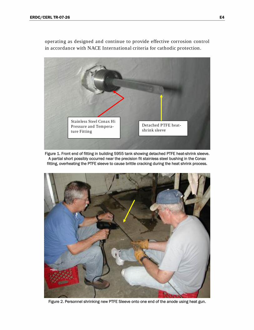
ERDC/CERL TR-07-26 E4
operating as designed and continue to provide effective corrosion control in accordance with NACE International criteria for cathodic protection.
Figure 1. Front end of fitting in building 5955 tank showing detached PTFE heat-shrink sleeve.
A partial short possibly occurred near the precision fit stainless steel bushing in the Conax fitting, overheating the PTFE sleeve to cause brittle cracking during the heat shrink process.
Figure 2. Personnel shrinking new PTFE Sleeve onto one end of the anode using heat gun.
Detached PTFE heat-shrink sleeve
Stainless Steel Conax Hi Pressure and Tempera-ture Fitting

ERDC/CERL TR-07-26 F1
Appendix F: ROI Assumptions, Calculations, and Validation Assumptions
Alternative 1
Fort Sill has 17 hot water tanks (37-1,000 gal) that are badly leaking and are projected to fail in 5 years, which must be replaced with new hot water tanks. These tanks cost an average of $16,500 to replace. In addition, there are 6 larger tanks (1,000 to 3,500 gallons) that are not leaking as badly, but are projected to fail, and be replaced in year 15. The average cost of re-placement of these tanks is $150,000 each, which includes not only the direct cost of the replacement tanks but also the cost of disconnecting and reconnecting the plumbing, and removing and rebuilding the brick wall in order to remove and replace the tanks. All of these new tanks are projected to last 20 years, and therefore a second replacement for the 17 tanks will be needed in year 25. This information is shown in the ROI spreadsheet under Baseline Cost. Prior to replacement, the 17 tanks will require annual maintenance cost of $35,000, for fixing leaks. Maintenance costs will be reduced at first, but will begin to increase until the second replacement in year 25, and afterward maintenance cost begin to increase again. The 17 leaking tanks from year 1 to 5 will result in additional cost ($600,000) due to water damage to structures, water damage to additional electri-cal/mechanical systems due to leaking tanks, cost of shower trucks, and sickness cause by mold due to leaks. These costs are initially $1.2M per year, but decrease after year 5, to $50,000, when the 17 tanks are replaced. The costs decrease again after year 15 (to $3,000), when the 6 tanks are replaced, however, the costs again increase to $13,000 until the 17 tanks that were replaced in year 5, are again replaced in year 25. These costs are shown under New Systems Benefits/Savings. There are no additional new benefits/savings until after year 30, as the 6 tanks replaced in year 15 are only 15 years old, and the 17 tanks that were last replaced in year 25 are only 5 years old; they will not start leaking again until after year 30.
Alternative 2
The investment cost for this alternative is $ 700,000. The 17 smaller tanks will be replaced in year 0 with new tanks having corrosion-resistant lin-

ERDC/CERL TR-07-26 F2
ings and built-in sacrificial anodes for corrosion protection, at an average cost of $16.5 K per tank. These tanks can be expected to last 30 years. Also, the 6 large (1,000 to 3,500 gal) existing tanks will be outfitted with im-pressed current ceramic anodes in year 0, at an average cost of $17.2 K per tank. These tanks will not need to be replaced until year 30. Annual main-tenance costs for these tanks are projected to be very low, ($500), and are shown in the ROI spreadsheet under New System Costs. The additional costs described in Alternative 1, will be avoided, and are shown under New Systems
Calculations
As shown on the spreadsheet, the potential return-on-investment for im-plementing ceramic anodes and new water tanks with corrosion resistant linings is projected to be 8.6.
700,000 `
8.56 Percent 856%
12,409 6,004,768 5,992,359
A B C D E F G HFuture Year
Baseline Costs Baseline Benefits/Savings
New System Costs
New System Benefits/Savings
Present Value of Costs
Present Value of Savings
Total Present Value
1 35,000 1,000 1,200,000 935 1,154,231 1,153,2962 35,000 1,000 1,200,000 873 1,078,649 1,077,7763 35,000 1,000 1,200,000 816 1,008,131 1,007,3144 35,000 1,000 1,200,000 763 942,182 941,4195 315,500 1,000 1,200,000 713 1,080,552 1,079,8396 2,000 1,000 50,000 666 34,648 33,9817 4,000 1,000 50,000 623 33,626 33,0038 6,000 1,000 50,000 582 32,592 32,0109 8,000 1,000 50,000 544 31,546 31,002
10 10,000 1,000 50,000 508 30,498 29,99011 12,000 1,000 50,000 475 29,456 28,98112 14,000 1,000 50,000 444 28,416 27,97213 16,000 1,000 50,000 415 27,390 26,97514 18,000 1,000 50,000 388 26,370 25,98315 916,500 1,000 3,000 362 333,227 332,86416 16,500 1,000 4,000 339 6,943 6,60517 16,500 1,000 5,000 317 6,807 6,49018 16,500 1,000 6,000 296 6,658 6,36219 16,500 1,000 7,000 277 6,498 6,22120 16,500 1,000 8,000 258 6,331 6,07221 35,000 1,000 9,000 242 10,626 10,38522 35,000 1,000 10,000 226 10,157 9,93123 35,000 1,000 11,000 211 9,701 9,49124 35,000 1,000 12,000 197 9,264 9,06725 282,500 1,000 13,000 184 54,431 54,24726 4,000 1,000 - 172 689 51727 6,000 1,000 - 161 965 80528 8,000 1,000 - 150 1,203 1,05329 10,000 1,000 - 141 1,406 1,26530 12,000 1,000 - 131 1,577 1,445
Return on Investment Calculation
Net Present Value of Costs and Benefits/Savings
Return on Investment Ratio
Investment Required

ERDC/CERL TR-07-26 F3
Backup Spreadsheet
Years Maintenance# Tanks replaced $/Tank
Replacement Costs Total Replacement Maintenance Total
Leak Damage Total
1 $35,000 $35,000 $1,000 $1,000 $1,500,000 $1,500,0002 $35,000 $35,000 $1,000 $1,000 $1,500,000 $1,500,0003 $35,000 $35,000 $1,000 $1,000 $1,500,000 $1,500,0004 $35,000 $35,000 $1,000 $1,000 $1,500,000 $1,500,0005 $35,000 17 $16,500 $280,500 $315,500 $1,000 $1,000 $1,500,000 $1,500,0006 $2,000 $2,000 $1,000 $1,000 $50,000 $50,0007 $4,000 $4,000 $1,000 $1,000 $50,000 $50,0008 $6,000 $6,000 $1,000 $1,000 $50,000 $50,0009 $8,000 $8,000 $1,000 $1,000 $50,000 $50,000
10 $10,000 $10,000 $1,000 $1,000 $50,000 $50,00011 $12,000 $12,000 $1,000 $1,000 $50,000 $50,00012 $14,000 $14,000 $1,000 $1,000 $50,000 $50,00013 $16,000 $16,000 $1,000 $1,000 $50,000 $50,00014 $18,000 $18,000 $1,000 $1,000 $50,000 $50,00015 $16,500 6 $150,000 $900,000 $916,500 $1,000 $1,000 $3,000 $3,00016 $16,500 $16,500 $1,000 $1,000 $4,000 $4,00017 $16,500 $16,500 $1,000 $1,000 $5,000 $5,00018 $16,500 $16,500 $1,000 $1,000 $6,000 $6,00019 $16,500 $16,500 $1,000 $1,000 $7,000 $7,00020 $16,500 $16,500 $1,000 $1,000 $8,000 $8,00021 $35,000 $35,000 $1,000 $1,000 $9,000 $9,00022 $35,000 $35,000 $1,000 $1,000 $10,000 $10,00023 $35,000 $35,000 $1,000 $1,000 $11,000 $11,00024 $35,000 $35,000 $1,000 $1,000 $12,000 $12,00025 $2,000 17 $16,500 $280,500 $282,500 $1,000 $1,000 $13,000 $13,00026 $4,000 $4,000 $1,000 $1,000 $0 $027 $6,000 $6,000 $1,000 $1,000 $0 $028 $8,000 $8,000 $1,000 $1,000 $0 $029 $10,000 $10,000 $1,000 $1,000 $0 $030 $12,000 $12,000 $0 $1,000 $1,000 $0 $0

ERDC/CERL TR-07-26 F4
ROI ANALYSIS CATHODIC PROTECTION AND HOT WATER TANK REPLACEMENT,
FT. SILL, OK
FY05 OSD Corrosion Project – ROI – AR-F-322
1.0 Introduction
1.1.1 Ft Sill has 17 hot water tanks (37- 1,000 gal) that are badly leaking and are projected to fail in 5 years, which must be replaced with new hot water tanks. In addition, there are 6 larger tanks (1,200 to 3,000 gallons) that are not leaking as badly, but are projected to fail, and be replaced in year 15. The average costs of replacement of these tanks include not only the direct cost of the replacement tanks but also the cost of disconnecting and reconnecting the plumbing, and removing and rebuilding the brick wall in order to remove and replace the tanks. All of the new tanks are projected to last 20 years, and a second replacement for the 24 tanks will be needed in year 25.
1.1.2 The 17 smaller tanks will be replaced in year 0 with new tanks hav-ing corrosion-resistant linings and built-in sacrificial anodes for corrosion protection. These tanks can be expected to last 30 years. Also, the 6 large (3,000 to 100,000 gal) existing tanks will be outfit-ted with impressed current ceramic anodes in year 0. These tanks will not need to be replaced until year 30.
1.1.3 A contract was awarded to Bushman & Associates, Inc. to design and provide cathodic protection for the 6 large diameter tanks. The cathodic systems for each tank utilize ceramic wire anodes, 50VDC and 12 ADC rectifier units, and each tank has an electrolytic gland port for measurement of cathodic protection potentials.
1.1.4 F.H. Haggerty Company, Inc. was awarded a contract to remove and replace seventeen (17) tanks. These tanks are to be lined and provided with sacrificial anode cathodic protection.
2.0 Executive Summary
2.1 Demonstration Project Overview
A demonstration project to design and install six (6) hot water stor-age tank protection systems was instituted at Ft. Sill. Ft. Sill utilizes large hot water storage tanks in mess hall and laundry building which cannot be removed from service except for short periods that
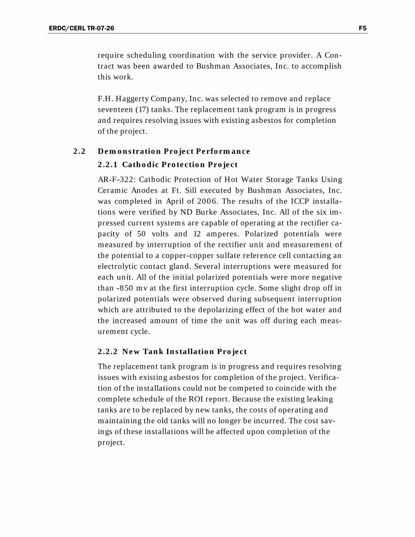
ERDC/CERL TR-07-26 F5
require scheduling coordination with the service provider. A Con-tract was been awarded to Bushman Associates, Inc. to accomplish this work.
F.H. Haggerty Company, Inc. was selected to remove and replace seventeen (17) tanks. The replacement tank program is in progress and requires resolving issues with existing asbestos for completion of the project.
2.2 Demonstration Project Performance
2.2.1 Cathodic Protection Project
AR-F-322: Cathodic Protection of Hot Water Storage Tanks Using Ceramic Anodes at Ft. Sill executed by Bushman Associates, Inc. was completed in April of 2006. The results of the ICCP installa-tions were verified by ND Burke Associates, Inc. All of the six im-pressed current systems are capable of operating at the rectifier ca-pacity of 50 volts and 12 amperes. Polarized potentials were measured by interruption of the rectifier unit and measurement of the potential to a copper-copper sulfate reference cell contacting an electrolytic contact gland. Several interruptions were measured for each unit. All of the initial polarized potentials were more negative than -850 mv at the first interruption cycle. Some slight drop off in polarized potentials were observed during subsequent interruption which are attributed to the depolarizing effect of the hot water and the increased amount of time the unit was off during each meas-urement cycle.
2.2.2 New Tank Installation Project
The replacement tank program is in progress and requires resolving issues with existing asbestos for completion of the project. Verifica-tion of the installations could not be competed to coincide with the complete schedule of the ROI report. Because the existing leaking tanks are to be replaced by new tanks, the costs of operating and maintaining the old tanks will no longer be incurred. The cost sav-ings of these installations will be affected upon completion of the project.

ERDC/CERL TR-07-26 F6
2.3 Cost and ROI
Table 1 presents a summary of the ROI values for the original pro-ject estimate and for the revised cost estimate. As indicated in Table I, the Net Present Value of Avoided Costs, Net Present Value of New System Costs, and Net Present value of Savings is the same for both ROI estimates because no changes were made to long term cost flow assumptions. The effect of the decrease in estimated New Sys-tem Costs is to increase the return on initial investment ratio from 8.68 to 13.42 and the Internal Rate of Return, IRR, percentage from 118% to 188%. It does not appear that the revised cost estimate sig-nificantly impacts the conclusion that based on either ROI analysis, the application of cathodic protection and tank replacement is justi-fied for the long term corrosion control of the Ft. Sill hot water storage tanks.
Table I. Comparison of ROI Estimates.
Financial Data Original ROI Revised ROI
New System Cost $700,000 $449,708
Net Present Value of Avoided Costs $6,074,535 $6,079,132
Net Present Value of New System Costs
$111,824 $45,598
Net Present Value of Savings $5,967,309 $6,033,534
ROI Ratio 8.68 13.42
ROI % 868% 1,3425
IRR 118% 188%
3.0 Technology Description 3.1 Cathodic Protection
3.1.1 Cathodic protection (CP) is a technique to control the corrosion of a metal surface by making that surface the cathode of an electrochemical cell. CP is a method commonly used to protect buried and submerges ferrous structures from corrosion. Cathodic protection systems are most com-monly used to protect ductile and cast iron water mains, bulk water storage tanks, domestic and commercial hot water hot water tanks, natural gas mains and pipelines, buried steel tanks; steel pier piles, ships, offshore oil platforms, and on-shore oil well casings.
3.1.2 The first use of CP was in 1852, when Sir Humphrey Davy, of the British Navy, attached chunks of iron to the external, be-

ERDC/CERL TR-07-26 F7
low water line, hull of a copper clad ship. Iron has a stronger tendency to corrode (rust) than copper and when connected to the hull, the corrosion rate of the copper was dramatically reduced. This original application of CP utilized the iron as sacrificial anodes. Today, galvanic or sacrificial anodes are made in various shapes using alloys of zinc, magnesium and aluminum. The electrochemical potential, current capacity, and consumption rate of these alloys make them excellent materials to use as galvanic anodes for use with ferrous al-loys.
3.1.3 Galvanic anodes are designed and selected to have a more "active" voltage (technically a more negative electrochemical potential) than the metal of the structure (typically steel). For effective CP, the potential of the steel surface is polarized (pushed) more negative until the surface has a uniform po-tential. At that stage, the driving force for the corrosion reac-tion is halted. The galvanic anode continues to corrode, con-suming the anode material until eventually it must be replaced. The polarization is caused by the current flow from the anode to the cathode. The driving force for the CP cur-rent flow is the difference in electrochemical potential be-tween the anode and the cathode. Galvanic anodes are lim-ited by their electrochemical potential to relatively low cathodic protection current outputs. Galvanic anodes are normally used for small isolated metallic components such as valves or fittings in plastic piping systems or for pipelines and mains with excellent coating systems on the meal sur-face.
3.1.4 Impressed Current CP is used for the larger structures that galvanic anodes cannot be used to economically deliver suffi-cient current to provide complete protection. Impressed Cur-rent Cathodic Protection (ICCP) systems use anodes con-nected to a DC power source (a cathodic protection rectifier). Anodes for ICCP systems are tubular and solid rod shapes or continuous wires or ribbons of various specialized materials. These include high silicon cast iron, graphite, mixed metal oxide, platinum and niobium coated wire and others.
3.1.5 A typical ICCP system for a hot water tank would include an AC powered rectifier with a maximum rated DC output of be-tween 5 and 50 amperes and 10 and 60 volts. The positive DC output terminal is connected via cables to the anode placed within the tank. Cable rated for the expected current output connects the negative terminal of the rectifier to the water tank. Due to the need to install wiring through the shell of the hot water tank, specialized pressure fittings with packing glands are required. The operating output of the rec-tifier is adjusted to the optimum level by a CP expert after

ERDC/CERL TR-07-26 F8
conducting various tests including measurements of electrochemical potential.
3.1.6 Testing and adjustment of both Galvanic CP and ICCP sys-tems is done by measuring the electrochemical potential with standard reference electrodes. Copper-copper(II) sulfate electrodes are typically used for structures in contact with soil or fresh water. Silver chloride electrodes are used for seawater applications. A high impedance voltmeter is con-nected between the structure of interest and the reference electrode. When obtaining potential data it is important to eliminate or minimize external voltage errors from the measurement. Measurement related errors can be minimized or eliminated by the use of high impedance voltmeters, cali-brated reference electrodes, and proper measurement proce-dures. It is common to use an electrolyte bridge style packing gland to permit the use of a portable reference electrode for potential measurements. Extraneous voltage errors caused by the flow of current through the measurement circuit, IR Drop Errors, are corrected by simultaneous interruption of all cathodic protection sources applicable to the structure or through the use of small buried coupons that are intercon-nected with the structure but which can be interrupted from the cathodic protection sources for measurement of its po-tential.
3.1.7 The two most commonly used evaluation criteria for cathodic protection are a polarized, IR Drop Error Free, potential of -850 millivolts or more negative or the formation of 100 mil-livolts of cathodic polarization on the structure related to the potential of the structure prior to the application of cathoidc protection. An alternate form of the 100 millivolt polariza-tion criteria is to disengage all cathodic protection sources and to measure the difference in the IR Drop Error Free po-tential and the structure potential at a later time period. Dur-ing the waiting interval the cathodic protection sources must remain disengaged. If the difference is 100 millivolts or more, adequate polarization has occurred for cathodic pro-tection.
3.1.8 Effective cathodic protection levels for various metals have been established and are published in industry standards. In the United States, the standards of NACE International are used to evaluate cathodic protection system operation and design. Among applicable standards for structures located at Ft. Sill, OK are:
NACE RP0169 Control of External Corrosion on Under-ground or Submerged Metallic Piping Systems,

ERDC/CERL TR-07-26 F9
NACE RPO388 Impressed Current Cathodic Protection of Internal Submerged Surfaces of Carbon Steel Water Storage Tanks,
3.1.9 Cathodic protection for corrosion control of buried or sub-merged metallic facilities has distinct advantages. Among these positive aspects are:
o Cathodic protection can be applied to both new and existing facilities.
o Cathodic protection can be used on both coated and non coated metallic structures.
o Cathodic protection can prevent corrosion from soil corro-sion, bacterial corrosion, and stress corrosion cracking.
o Cathodic protection is applicable over a wide range of envi-ronmental conditions.
o The effectiveness of cathodic protection can be measured to ensure proper corrosion control levels are maintained.
3.1.10 Cathodic Protection has some limitations. Among these limi-tations are:
o Cathodic protection requires expert services for proper de-sign and layout of an integrated corrosion control system. An oversight is needed to ensure that cathodic protection sys-tems are compatible.
o Cathodic protection cannot restore metal to previously cor-roded surfaces.
3.1.11 Cathodic protection is an active process and requires moni-toring and prompt repair of deficiencies. Items subject to damage by third party actions such as positive and negative cables and anodes require continual oversight and prompt repairs when needed.
3.1.12 Changes to the protected structure can negate the cathodic protection system. Changes in water temperature or flow rate may require adjustment of the cathodic protection cur-rent output from the rectifiers.
3.2 Replacement with State of the Art Hot Water Tanks
3.2.1 Present coating technology provides a durable and reliable glass lining for new hot water tanks. Most manufacturers of hot water tanks provide galvanic cathodic protection in the form of magnesium rod(s). It is probable for to obtain a thirty (30) years service life for domestic hot water heating tanks. The service life is based on the projected service life of the magnesium anodes plus a time allowance for corrosion to proceed.
3.2.2 New hot water tanks have several advantages.

ERDC/CERL TR-07-26 F10
o Improved coating systems and cathodic protection can ex-tend the service life of the hot water tanks
o Maintenance costs due to plumping repairs and water dam-age are avoided.
3.2.3 New hot water tanks have two limitations.
o To obtain the full service life the tanks must be installed with sufficient care to avoid damage to internal linings.
o Changes in the corrosiveness of the supplied water can alter the expected service life of the tanks.
4.0 Demonstration Project
4.1 Cathodic Protection Project
4.1.1 Overview
A demonstration project to design and install six (6) hot water stor-age tank protection systems was instituted at Ft. Sill. Ft. Sill utilizes large hot water storage tanks in mess hall and laundry building which cannot be removed from service except for short periods that require scheduling coordination with the service provider. A Con-tract was been awarded to Bushman Associates, Inc. to accomplish this work.
4.1.2 Demonstration Cathodic Protection Project
Bushman Associates, Inc. provided six (6) rectifier and ceramic an-ode wire anode cathodic protection systems. These cathodic protec-tion systems consisted of a wire type ceramic anode installed longi-tudinally within the tank and along the centerline. The anodes are powered with rectifier units rated at 50 volts DC and 12 amperes DC. The six locations provided with ICCP are shown in Table 2a.
Table 2a. ICCP Installations.
Tank No. Manufacturer Bldg. No. Length (in.) Diameter (in.) Capacity (Gal) Age (Years)
1 Southgate Engineering 5955 136 72 2685 20
2 Old Dominion 5960 144 52 1472 18
3 Old Dominion 5960 144 52 1472 18
4 Unknown 5970 148 56 1737 Unknown
5 Unknown 5970 148 56 1737 Unknown
6 Wendland Mfg. 6050 140 78 2655 Unknown

ERDC/CERL TR-07-26 F11
4.2 New Tank Installation
4.2.1 Overview Seventeen (17) of the remaining hot water tanks at Ft. Sill were selected for replacement. These tanks are indicated in Table 2.
4.2.2 New Tank Demonstration Project
F.H. Haggerty Company, Inc. was selected to remove and re-place the tanks indicated in Table 2b. The replacement tank program is in progress and requires resolving issues with ex-isting asbestos for completion of the project.
Table 2b. Replaced Tanks.
Building Capacity Gallons
1/1/5690 1138
1/2/5690 40
1/3/5690 120
1/1/5672 37
1/1/5673 37
1/1/5678 855
1/2/5678 855
1/3/5678 855
1/2/2812 275
1/2/1607 500
1/3/1607 37
1/4/1601 37
1/1/1605 600
1/1/1603 1100
1/1/2470 908
1/2/2470 37
1/3/2428 37
5.0 Demonstration Project Performance
5.1 Cathodic Protection Project
AR-F-322: Cathodic Protection of Hot Water Storage Tanks Using Ceramic Anodes at Ft. Sill executed by Bushman Associates, Inc. was completed in April of 2006. The results of the ICCP installa-tions were verified by ND Burke Associates, Inc. All of the six im-pressed current systems are capable of operating at the rectifier ca-pacity of 50 volts and 12 amperes. Polarized potentials were

ERDC/CERL TR-07-26 F12
measured by interruption of the rectifier unit and measurement of the potential to a copper-copper sulfate reference cell contacting an electrolytic contact gland. Several interruptions were measured for each unit. All of the initial polarized potentials were more negative than -850 mv at the first interruption cycle. Some slight drop off in polarized potentials were observed during subsequent interruption which are attributed to the depolarizing effect of the hot water and the increased amount of time the unit was off during each meas-urement cycle.
5.2 New Tank Installation Project
The replacement tank program is in progress and requires resolving issues with existing asbestos for completion of the project. Verifica-tion of the installations could not be competed to coincide with the complete schedule of the ROI report. Because the existing leaking tanks are to be replaced by new tanks, the costs of operating and maintaining the old tanks will no longer be incurred. The cost sav-ings of these installations will be affected upon completion of the project.
6.0 Costs and ROI
6.1 Demonstration Project Costs
Cost information obtained from Bushman Associates, Inc. indicates that AR-F-322: Cathodic Protection of Hot Water Storage Tanks Using Ceramic Anodes at Ft. Sill had a total contract value of $103,525. From this cost unit costs could be estimated for each of the work scope items.
The estimated unit cost for installation of an ICCP system with ceramic anodes was $17,260 per unit. This cost includes engineering design and ICCP start-up after installation.
The proposal of F.H Haggerty Company, Inc. indicated a total cost of $196,280 for the replacement of 17 tanks. The range of capacity levels for the replacement tanks varies and should provide a reasonable aver-age cost based on a larger population of tanks.
The unit cost for the replacement tanks was $11,550 per unit. This cost includes removal of the old tanks and replacement with a new tank.

ERDC/CERL TR-07-26 F13
Table 3. Comparison of ROI Estimates.
Financial Data Original ROI Revised ROI
New System Cost $700,000 $449,708
Net Present Value of Avoided Costs $6,074,535 $6,079,132
Net Present Value of New System Costs
$111,824 $45,598
Net Present Value of Savings $5,967,309 $6,033,534
ROI Ratio 8.68 13.42
ROI % 868% 1,3425
IRR 118% 188%
6.2 Comparison of Base and Revised ROI Studies
6.2.1 The original ROI study is presented in Table 4 and Table 4A. The information within these tables and the calculations are as presented in the FY05 OSD Corrosion Project – ROI – AR-F-322. There are slight differences in numerical values that are attributed to the numerical precision of the calcula-tions and equations. A change was made in the estimated operating costs of the new system for both the Base ROI and the Revised ROI from $8,000 per year to $500 per year as no indication for the $8,000 operating cost was included in the scenario description and no reason for such a cost related to the operation of ICCP systems was apparent.
6.2.2 In the Base ROI replacement of the tanks was assumed in year 30 for the New System. For the Base ROI Old System costs, replacement of the tanks was previously completed and no replacement in year 30 is anticipated.
6.2.3 In the Revised ROI replacement of the tanks is assumed in Year 30 as the new tanks will have ended their service life cy-cle and the cathodic protection system would require re-placement. Costs for replacements are based on the costs for the new tanks and cathodic protection system.
6.2.4 The Revised ROI study is presented in Table 5 and Table 5A. The Revised ROI study assumes that the overhead burden for project management of the demonstration project would be substantially higher than for a standard public works con-tract. The need to coordinate technology transfer and assess the value of the new technical would not be required within a standard contract.

ERDC/CERL TR-07-26 F14
6.2.5 ND Burke Associates, Inc. estimates that the demonstration overhead burden required of this demonstration project was about 75% of the direct contractor costs. The combined ICCP and new tank costs are about $400,000. The investment re-quired as shown in the Base ROI calculation is $700,000. $300,000 of the $700,000 is assumed to be demonstration project overhead. For a standard public works contract, an assumed overhead burden of 50% of the direct contractor costs is applied due to the removal of the research portion of the project costs.
6.2.6 The investment required used in the Revised ROI cost study adjusted for the actual contract amounts and a 50% project administration burden is $449,708. The required investment amount is reduced from the original evaluation due to the reduction in replaced tanks from 24 to 17 and the reduction of administrative costs from 75% to 50%.

ERD
C/C
ERL TR
-07-26 F15
Table 4. Base ROI calculation for cathodic protection and new tank replacements at Fort Sill, OK.
Cost of Money 7% IRR 118% Return on Invest-ment Ratio 8.68 ROI Percent 868%
Net Present Value of New System Costs $111,824
Net Present Value of Savings $6,074,535
Total Net Present Value $5,967,309
A B C D E F G H
Future Year Baseline Cost Baseline Bene-fits/Savings New System Cost
New System Bene-fits/Savings PV of Costs PV of Savings Total PV
0 -$700,000 -$700,000
1 $35,000 $500 $900,000 $467 $873,832 $873,365
2 $35,000 $500 $900,000 $437 $816,665 $816,228
3 $35,000 $500 $900,000 $408 $763,239 $762,831
4 $35,000 $500 $900,000 $381 $713,307 $712,926
5 $447,500 $500 $900,000 $357 $960,749 $960,392
6 $35,000 $500 $50,000 $333 $56,639 $56,306
7 $35,000 $500 $50,000 $311 $52,934 $52,622
8 $35,000 $500 $50,000 $291 $49,471 $49,180
9 $35,000 $500 $50,000 $272 $46,234 $45,962
10 $35,000 $500 $50,000 $254 $43,210 $42,956
11 $35,000 $500 $50,000 $238 $40,383 $40,145
12 $35,000 $500 $50,000 $222 $37,741 $37,519
13 $35,000 $500 $50,000 $207 $35,272 $35,064
14 $35,000 $500 $50,000 $194 $32,964 $32,771
15 $1,085,000 $500 $50,000 $181 $411,376 $411,195
16 $35,000 $500 $3,000 $169 $12,872 $12,703
17 $35,000 $500 $40,000 $158 $23,743 $23,585
18 $35,000 $500 $200,000 $148 $69,528 $69,380
19 $35,000 $500 $400,000 $138 $120,281 $120,143

ERD
C/C
ERL TR
-07-26 F16
Table 4 Continued
Future Year Baseline Cost Baseline Benefits/Savings New System Cost
New System Benefits/Savings PV of Costs PV of Savings Total PV
20 $35,000 $500 $520,000 $129 $143,423 $143,293
21 $35,000 $500 $600,000 $121 $153,361 $153,240
22 $35,000 $500 $600,000 $113 $143,328 $143,215
23 $35,000 $500 $600,000 $105 $133,951 $133,846
24 $35,000 $500 $600,000 $99 $125,188 $125,090
25 $447,500 $500 $600,000 $92 $193,001 $192,909
26 $35,000 $500 $0 $86 $6,027 $5,941
27 $35,000 $500 $0 $80 $5,633 $5,552
28 $35,000 $500 $0 $75 $5,264 $5,189
29 $35,000 $500 $0 $70 $4,920 $4,849
30 $35,000 $804,500 $0 $105,685 $4,598 -$101,087

ERD
C/C
ERL TR
-07-26 F17
Table 4A. Backup spreadsheet base scenario.
Old System Costs New System Costs
O & M Costs
Year Maintenance # Tanks Replaced
Unit Cost Replacement Cost
Total Cost Total Avoided Costs Operating Costs
Replacement Total
0
1 $35,000 $35,000 $900,000 $500 $500
2 $35,000 $35,000 $900,000 $500 $500
3 $35,000 $35,000 $900,000 $500 $500
4 $35,000 $35,000 $900,000 $500 $500
5 $35,000 25 16,500 412,500 $447,500 $900,000 $500 $500
6 $35,000 $35,000 $50,000 $500 $500
7 $35,000 $35,000 $50,000 $500 $500
8 $35,000 $35,000 $50,000 $500 $500
9 $35,000 $35,000 $50,000 $500 $500
10 $35,000 $35,000 $50,000 $500 $500
11 $35,000 $35,000 $50,000 $500 $500
12 $35,000 $35,000 $50,000 $500 $500
13 $35,000 $35,000 $50,000 $500 $500
14 $35,000 $35,000 $50,000 $500 $500
15 $35,000 7 150,000 1,050,000 $1,085,000 $50,000 $500 $500
16 $35,000 $35,000 $3,000 $500 $500
17 $35,000 $35,000 $40,000 $500 $500
18 $35,000 $35,000 $200,000 $500 $500
19 $35,000 $35,000 $400,000 $500 $500
20 $35,000 $35,000 $520,000 $500 $500
21 $35,000 $35,000 $600,000 $500 $500

ERD
C/C
ERL TR
-07-26 F1
8
Table 4A Continued
Old System Costs New System Costs
O & M Costs
Year Maintenance # Tanks Replaced
Unit Cost Replacement Cost
Total Cost Total Avoided Costs Operating Costs
Replacement Total
22 $35,000 $35,000 $600,000 $500 $500
23 $35,000 $35,000 $600,000 $500 $500
24 $35,000 $35,000 $600,000 $500 $500
25 $35,000 25 16,500 412,500 $447,500 $600,000 $500 $500
26 $35,000 $35,000 $0 $500 $500
27 $35,000 $35,000 $0 $500 $500
28 $35,000 $35,000 $0 $500 $500
29 $35,000 $35,000 $0 $500 $500
30 $35,000 $35,000 $0 $500 $1,296,000 $1,296,500

ERD
C/C
ERL TR
-07-26 F19
Table 5. Revised ROI caculation for cathodic protection and new tank replacements at Fort Sill, OK.
Cost of Money 7% IRR 188% ROI ratio 13.42 Percent 1,342%
NPV of New System Costs $45,598 NPV of Savings $6,079,132
Total NPV $6,033,534
Future Year Baseline Cost Baseline Benefits/Savings New System Cost
New System Benefits/Savings PV of Costs PV of Savings Total PV
0 $449,708 -$449,708
1 $35,000 $500 $900,000 $467 $873,832 $873,365
2 $35,000 $500 $900,000 $437 $816,665 $816,228
3 $35,000 $500 $900,000 $408 $763,239 $762,831
4 $35,000 $500 $900,000 $381 $713,307 $712,926
5 $447,500 $500 $900,000 $357 $960,749 $960,392
6 $35,000 $500 $50,000 $333 $56,639 $56,306
7 $35,000 $500 $50,000 $311 $52,934 $52,622
8 $35,000 $500 $50,000 $291 $49,471 $49,180
9 $35,000 $500 $50,000 $272 $46,234 $45,962
10 $35,000 $500 $50,000 $254 $43,210 $42,956
11 $35,000 $500 $50,000 $238 $40,383 $40,145
12 $35,000 $500 $50,000 $222 $37,741 $37,519
13 $35,000 $500 $50,000 $207 $35,272 $35,064
14 $35,000 $500 $50,000 $194 $32,964 $32,771
15 $1,085,000 $500 $50,000 $181 $411,376 $411,195
16 $35,000 $500 $3,000 $169 $12,872 $12,703
17 $35,000 $500 $40,000 $158 $23,743 $23,585
18 $35,000 $500 $200,000 $148 $69,528 $69,380
19 $35,000 $500 $400,000 $138 $120,281 $120,143
20 $35,000 $500 $520,000 $129 $143,423 $143,293
21 $35,000 $500 $600,000 $121 $153,361 $153,240

ERD
C/C
ERL TR
-07-26 F20
Table 5 Continued
Future Year Baseline Cost Baseline Benefits/Savings New System Cost
New System Benefits/Savings PV of Costs PV of Savings Total PV
22 $35,000 $500 $600,000 $113 $143,328 $143,215
23 $35,000 $500 $600,000 $105 $133,951 $133,846
24 $35,000 $500 $600,000 $99 $125,188 $125,090
25 $447,500 $500 $600,000 $92 $193,001 $192,909
26 $35,000 $500 $0 $86 $6,027 $5,941
27 $35,000 $500 $0 $80 $5,633 $5,552
28 $35,000 $500 $0 $75 $5,264 $5,189
29 $35,000 $500 $0 $70 $4,920 $4,849
30 $35,000 $300,375 $0 $39,459 $4,598 -$34,862

ERD
C/C
ERL TR
-07-26 F21
Table 5A. Backup spreadsheet base scenario.
Old System Costs New System Costs
O & M Costs
Year Maintenance # Tanks Replaced
Unit Cost Repalcement Cost
Total Cost Total Avoided Costs Operating Costs
Replacement Total
0
1 $35,000 $35,000 $900,000 $500 $500
2 $35,000 $35,000 $900,000 $500 $500
3 $35,000 $35,000 $900,000 $500 $500
4 $35,000 $35,000 $900,000 $500 $500
5 $35,000 17 11,550 196,350 $231,350 $900,000 $500 $500
6 $35,000 $35,000 $50,000 $500 $500
7 $35,000 $35,000 $50,000 $500 $500
8 $35,000 $35,000 $50,000 $500 $500
9 $35,000 $35,000 $50,000 $500 $500
10 $35,000 $35,000 $50,000 $500 $500
11 $35,000 $35,000 $50,000 $500 $500
12 $35,000 $35,000 $50,000 $500 $500
13 $35,000 $35,000 $50,000 $500 $500
14 $35,000 $35,000 $50,000 $500 $500
15 $35,000 6 150,000 900,000 $935,000 $50,000 $500 $500
16 $35,000 $35,000 $3,000 $500 $500
17 $35,000 $35,000 $40,000 $500 $500
18 $35,000 $35,000 $200,000 $500 $500
19 $35,000 $35,000 $400,000 $500 $500
20 $35,000 $35,000 $520,000 $500 $500
21 $35,000 $35,000 $600,000 $500 $500

ERD
C/C
ERL TR
-07-26 F22
Table 5A Continued
Old System Costs New System Costs
O & M Costs
Year Maintenance # Tanks Replaced
Unit Cost Replacement Cost
Total Cost Total Avoided Costs Operating Costs
Replacement Total
22 $35,000 $35,000 $600,000 $500 $500
23 $35,000 $35,000 $600,000 $500 $500
24 $35,000 0 $35,000 $600,000 $500 $500
25 $35,000 17 11,550 196,350 $231,350 $600,000 $500 $500
26 $35,000 $35,000 $0 $500 $500
27 $35,000 $35,000 $0 $500 $500
28 $35,000 $35,000 $0 $500 $500
29 $35,000 $35,000 $0 $500 $500
30 $35,000 $35,000 $0 $500 $299,875 $300,375

NSN 7540-01-280-5500 Standard Form 298 (Rev. 8-98) Prescribed by ANSI Std. 239.18
REPORT DOCUMENTATION PAGE Form Approved OMB No. 0704-0188
Public reporting burden for this collection of information is estimated to average 1 hour per response, including the time for reviewing instructions, searching existing data sources, gathering and maintaining the data needed, and completing and reviewing this collection of information. Send comments regarding this burden estimate or any other aspect of this collection of information, including suggestions for reducing this burden to Department of Defense, Washington Headquarters Services, Directorate for Information Operations and Reports (0704-0188), 1215 Jefferson Davis Highway, Suite 1204, Arlington, VA 22202-4302. Respondents should be aware that notwithstanding any other provision of law, no person shall be subject to any penalty for failing to comply with a collection of information if it does not display a currently valid OMB control number. PLEASE DO NOT RETURN YOUR FORM TO THE ABOVE ADDRESS. 1. REPORT DATE (DD-MM-YYYY)
June 2007 2. REPORT TYPE
Final3. DATES COVERED (From - To)
5a. CONTRACT NUMBER 5b. GRANT NUMBER
4. TITLE AND SUBTITLE Cathodic Protection of Hot Water Tanks at Fort Sill: Final Report on Project AR-F-322 for FY05
5c. PROGRAM ELEMENT NUMBER Corrrosion Prevention and Control 5d. PROJECT NUMBER CPC AR-F-322 5e. TASK NUMBER MIPR5CCERB1011, MIPR5CROBB1012
6. AUTHOR(S) L.D. Stephenson, Ashok Kumar, and J. Bushman
5f. WORK UNIT NUMBER 8. PERFORMING ORGANIZATION REPORT
NUMBER 7. PERFORMING ORGANIZATION NAME(S) AND ADDRESS(ES) U.S. Army Engineer Research and Development Center Construction Engineering Research Laboratory PO Box 9005 Champaign, IL 61826-9005
ERDC/CERL TR-07-26
9. SPONSORING / MONITORING AGENCY NAME(S) AND ADDRESS(ES) 10. SPONSOR/MONITOR’S ACRONYM(S) U.S. Army Installation Management Command
Engineering Office, Directorate of Public Works (IMPW-E) 2511 Jefferson Davis Hwy. Arlington, VA 22202
11. SPONSOR/MONITOR’S REPORT NUMBER(S)
OSD CPC AR-F-322
12. DISTRIBUTION / AVAILABILITY STATEMENT Approved for public release; distribution is unlimited.
13. SUPPLEMENTARY NOTES
14. ABSTRACT
This corrosion prevention and control project demonstrated the use of ceramic anodes for impressed current cathodic protection (ICCP) systems for retrofitting in six large 1,000 to 3,500 gallon hot water storage tanks that service barracks and adjoining mess halls at Fort Sill, OK. The cathodic protection systems were designed to provide corrosion protection to the bare steel interior of the tanks that are susceptible to corrosion. This is a first time installation of horizontal anode in large hot water storage tank ASME Pressure Vessel with no man-ways. These cathodic protection systems have continued to operate as designed since their initial operation in April 2006 and have provided complete corrosion control since their original installation. The lifetimes of these large tanks are expected to be ex-tended by 30 years as a result of installing the ICCP systems using ceramic coated (mixed metal oxide) anodes. In addition, 17 smaller hot water tanks and hot water heaters (37 to 1,000 gal) were replaced with new hot water tanks and hot water heaters with factory-installed sacrificial anodes and glass linings. For the smaller tanks, it is more economical to use glass linings and sacrificial anodes than ICCP systems.
15. SUBJECT TERMS Fort Sill, OK; corrosion prevention; cathodic protection; hot water storage tanks; impressed current cathodic protection (ICCP)
17. LIMITATION OF ABSTRACT
18. NUMBER OF PAGES
19a. NAME OF RESPONSIBLE PERSON
a. REPORT Unclassified
b. ABSTRACT Unclassified
c. THIS PAGE Unclassified
148
19b. TELEPHONE NUMBER (include area code)


![cathodic protection in practise · 2 [CATHODIC PROTECTION/BM] CATHODIC PROTECTION P E FRANCIS 1 INTRODUCTION The first practical use of cathodic protection is generally credited to](https://static.fdocuments.in/doc/165x107/5ace93c87f8b9ae2138b87e4/cathodic-protection-in-cathodic-protectionbm-cathodic-protection-p-e-francis.jpg)