A History of Collapse Factor Modeling and Empirical Data for …€¦ · A History of Collapse...
55
Page 1 of 29 ______________ American Instititute of Aeronautics and Astronautics A History of Collapse Factor Modeling and Empirical Data for Cryogenic Propellant Tanks Laurence de Quay * NASA Stennis Space Center, MS, 39529, USA B. Keith Hodge † Mississippi State University, MS, 39762, USA One of the major technical problems associated with cryogenic liquid propellant systems used to supply rocket engines and their subassemblies and components is the phenomenon of propellant tank pressurant and ullage gas collapse. This collapse is mainly caused by heat transfer from ullage gas to tank walls and interfacing propellant, which are both at temperatures well below those of this gas. Mass transfer between ullage gas and cryogenic propellant can also occur and have minor to significant secondary effects that can increase or decrease ullage gas collapse. Pressurant gas is supplied into cryogenic propellant tanks in order to initially pressurize these tanks and then maintain required pressures as propellant is expelled from these tanks. The net effect of pressurant and ullage gas collapse is increased total mass and mass flow rate requirements of pressurant gases. For flight vehicles this leads to significant and undesirable weight penalties. For rocket engine component and subassembly ground test facilities this results in significantly increased facility hardware, construction, and operational costs. “Collapse Factor” is a parameter used to quantify the pressurant and ullage gas collapse. Accurate prediction of collapse factors, through analytical methods and modeling tools, and collection and evaluation of collapse factor data has evolved over the years since the start of space exploration programs in the 1950’s. Through the years, numerous documents have been published to preserve results of studies associated with the collapse factor phenomenon. This paper presents a summary and selected details of prior literature that document the aforementioned studies. Additionally other literature that present studies and results of heat and mass transfer processes, related to or providing important insights or analytical methods for the studies of collapse factor, are presented. I. INTRODUCTION Following initial developmental work in the 1920’s and 1930’s by Robert H. Goddard, liquid propellant rockets have been further developed and utilized extensively for military missile, earth-to-orbit launch system, and space propulsion-system applications. The vast majority of larger high thrust (greater than 44,000 N or 10,000 lb) liquid propellant rockets utilize one or more cryogenic liquid propellants because of the high combustion-energy-to-mass ratio or high combustion energy to volume ratio provided with these types of propellants. The more than 80-year history of liquid propellant rockets has been a series of continuous improvements in propulsive efficiency, increased thrust levels, significant increases in thrust-to-weight ratios, and an expanding variety of engine cycles. Initiatives starting in the late 1980’s have placed the emphasis on reduction of costs with improved reliability and safety in the manufacture, ground testing, and operation of all rocket propulsion systems. Further development initiatives starting in the middle 1990’s have included renewed interest in liquid-oxidizer-solid-fuel (hybrid) rocket motors and liquid propellant rocket engines with oxidizer-rich, staged-combustion power cycles or unchoked low differential pressure propellant injectors. These initiatives have necessitated the use of ground test facilities with cryogenic run systems operating at high subcritical and supercritical pressures. * Aerospace Engineer, NASA/SSC Mail Stop EA33, SSC, MS, Associate Fellow † Professor of Mechanical Engineering, Mail Stop 9552, Mississippi State, MS, Associate Fellow RELEASED - Printed documents may be obsolete; validate prior to use. https://ntrs.nasa.gov/search.jsp?R=20100026018 2020-05-19T06:40:32+00:00Z
Transcript of A History of Collapse Factor Modeling and Empirical Data for …€¦ · A History of Collapse...

Page 1 of 29
______________
American Instititute of Aeronautics and Astronautics
A History of Collapse Factor Modeling and
Empirical Data for Cryogenic Propellant Tanks
Laurence de Quay*
NASA Stennis Space Center, MS, 39529, USA
B. Keith Hodge†
Mississippi State University, MS, 39762, USA
One of the major technical problems associated with cryogenic liquid propellant systems
used to supply rocket engines and their subassemblies and components is the phenomenon of
propellant tank pressurant and ullage gas collapse. This collapse is mainly caused by heat
transfer from ullage gas to tank walls and interfacing propellant, which are both at
temperatures well below those of this gas. Mass transfer between ullage gas and cryogenic
propellant can also occur and have minor to significant secondary effects that can increase or
decrease ullage gas collapse. Pressurant gas is supplied into cryogenic propellant tanks in order
to initially pressurize these tanks and then maintain required pressures as propellant is expelled
from these tanks. The net effect of pressurant and ullage gas collapse is increased total mass
and mass flow rate requirements of pressurant gases. For flight vehicles this leads to significant
and undesirable weight penalties. For rocket engine component and subassembly ground test
facilities this results in significantly increased facility hardware, construction, and operational
costs. “Collapse Factor” is a parameter used to quantify the pressurant and ullage gas collapse.
Accurate prediction of collapse factors, through analytical methods and modeling tools, and
collection and evaluation of collapse factor data has evolved over the years since the start of
space exploration programs in the 1950’s. Through the years, numerous documents have been
published to preserve results of studies associated with the collapse factor phenomenon. This
paper presents a summary and selected details of prior literature that document the
aforementioned studies. Additionally other literature that present studies and results of heat
and mass transfer processes, related to or providing important insights or analytical methods
for the studies of collapse factor, are presented.
I. INTRODUCTION
Following initial developmental work in the 1920’s and 1930’s by Robert H. Goddard, liquid propellant rockets
have been further developed and utilized extensively for military missile, earth-to-orbit launch system, and space
propulsion-system applications. The vast majority of larger high thrust (greater than 44,000 N or 10,000 lb) liquid
propellant rockets utilize one or more cryogenic liquid propellants because of the high combustion-energy-to-mass
ratio or high combustion energy to volume ratio provided with these types of propellants.
The more than 80-year history of liquid propellant rockets has been a series of continuous improvements in
propulsive efficiency, increased thrust levels, significant increases in thrust-to-weight ratios, and an expanding
variety of engine cycles.
Initiatives starting in the late 1980’s have placed the emphasis on reduction of costs with improved reliability and
safety in the manufacture, ground testing, and operation of all rocket propulsion systems. Further development
initiatives starting in the middle 1990’s have included renewed interest in liquid-oxidizer-solid-fuel (hybrid) rocket
motors and liquid propellant rocket engines with oxidizer-rich, staged-combustion power cycles or unchoked low
differential pressure propellant injectors. These initiatives have necessitated the use of ground test facilities with
cryogenic run systems operating at high subcritical and supercritical pressures.
*Aerospace Engineer, NASA/SSC Mail Stop EA33, SSC, MS, Associate Fellow
†Professor of Mechanical Engineering, Mail Stop 9552, Mississippi State, MS, Associate Fellow
RELEASED - Printed documents may be obsolete; validate prior to use.
https://ntrs.nasa.gov/search.jsp?R=20100026018 2020-05-19T06:40:32+00:00Z

Page 2 of 29
______________
American Instititute of Aeronautics and Astronautics
A. Flight Vehicles
All flight vehicles propelled by liquid propellant and hybrid rocket engines require one or more pressurized
propellant tanks in which propellant is expelled from tanks to supply one or more rocket engines. A simplified
schematic of a pump fed liquid propulsion system, which employs one of the simple basic power cycles, is shown
in Figure 1. In this system, turbopumps boost the pressures of propellants supplied from the propellant tanks such
that these propellants can be injected into the rocket engine’s thrust (main combustion) chamber denoted in the
Figure.
Figure 1 is obtained from Ref. 1 and a more detailed discussion about liquid propellant rockets is also presented in
this reference.
Figure 1. Simplified Schematic of a Typical Pump Fed Liquid Rocket
Propulsion System (Gas Generator Cycle, Single Turbine Driving
Both Turbopumps)
B. Ground Test Facilities
A key and critical component for design concept evaluation, development, flight certification, and subsequent use
of rocket propulsion systems is the ground testing of rocket engine assemblies, subassemblies, and components as
well as integrated rocket stages and major segments of the flight vehicle. The ground testing of individual rocket
engine components and subassemblies during the early stages of development has been given increased attention
and importance due to the aforementioned cost reduction and reliability and safety enhancement initiatives started
in the late 1980’s. Additionally, increased complexity and higher propulsion system pressures associated with a
number of recent liquid propellant rockets to increase propulsive efficiency has emphasized the importance of
rocket engine component and subassembly ground testing.
For the majority of high-thrust liquid propellant rocket engines and hybrid rocket motors, where one or more
pressurized cryogenic propellants are used, a high fidelity and performance ground testing facility is essential. This
facility normally operates one to three low- and high-pressure cryogenic propellant feed (run) systems that supply
propellants to rocket engine assembly, subassembly, or component test articles at required interface pressures and
RELEASED - Printed documents may be obsolete; validate prior to use.

Page 3 of 29
______________
American Instititute of Aeronautics and Astronautics
mass flow rates. For the cases where rocket engine subassemblies and components, such as turbopumps and
combustion devices, are ground tested, at least one of the test facility cryogenic propellant run systems operates at
high subcritical or supercritical pressures. (Critical pressures for oxygen, nitrogen, and hydrogen are 187.5-psia,
493.0-psia, and 731.2-psia respectively.) In all cases, the ground testing facility is required to simulate the
remaining propulsion system or flight vehicle by providing required propellant pressures, mass flows, and
temperatures at main fluid interfaces of the component being tested.
Figure 2 shows a simplified schematic of a ground test facility cryogenic propellant feed system, which supplies
propellant to a typical interface on a test article.
Figure 2. Simplified Schematic of a Cryogenic Propellant Feed System
1. Cryogenic Run Tank
The main component of the cryogenic propellant feed (or run) system is the cryogenic propellant run tank. This
component serves as the system reservoir where liquid or cold supercritical cryogenic propellant; typically liquid
oxygen, liquid hydrogen, or liquid methane; is expelled under pressure at the main discharge nozzle. This
propellant is conveyed via a cryogenic propellant run system, comprised of series of pipelines that generally
includes valves, filtration device, and flow meter(s), to one or more of the test article interfaces. The cryogenic run
tank main discharge nozzle is located at or near the lowest point of the tank such that nearly all propellant can be
expelled from the tank.
Referring to Figure 2, the internal volume of the cryogenic run tank is comprised of two regions, the propellant
region and the ullage-gas region.
Pressurant gas needs to be supplied into the ullage gas region as the volume or internal pressure of this region
increases. This pressurant gas is normally supplied by one of two methods. In one method, called the autogenous
tank pressurant gas supply method, a portion of the liquid or supercritical cryogen exiting the main discharge of the
run tank is vaporized or heated by a heat exchanger and is then routed into the tank ullage region at one or more
entry points near the top of the tank. For the other method, called the external pressurant gas supply method,
pressurant gas is supplied into the tank ullage externally from one or more gas bottles or other sources.
For cryogenic propellant run systems used on ground testing facilities, the external pressurant gas supply method is
generally employed. Pressurized gas bottles, as shown in Figure 2, provide this gas via a series of pipelines and
components to the cryogenic run tank ullage.
RELEASED - Printed documents may be obsolete; validate prior to use.

Page 4 of 29
______________
American Instititute of Aeronautics and Astronautics
2. Pressurant Gas Subsystem
The pressurant gas subsystem supplies all or most of the additional gas needed in the run tank ullage for
maintaining required cryogenic run tank pressures as propellant is expelled from the tank. The pressurant gas
subsystem is depicted as the gas bottles and pipelines with associated components between these bottles and the
cryogenic run tank ullage gas region in Figure 2.
3. Heat and Mass Transfer Processes in the Cryogenic Run Tank
Unique heat and mass transfer processes occur in cryogenic propellant tanks. These tanks (and flight vehicle
propellant tanks) have propellant regions and tank walls that are generally tens to hundreds of degrees R colder than
most of the ullage and the pressurant gases that enter the ullage gas regions. This results in significant rates of heat
transfer from the ullage gas region to tank walls and the cryogenic propellant. Subsequently this heat transfer
reduces the temperatures of the ullage gas region, thereby causing it’s mean density to increase (as compared to the
ideal condition where negligible heat transfer takes place). This increase in mean ullage gas density is known as
ullage gas collapse and has the net effect of increasing the mass flow rate and total mass accumulation of pressurant
gas entering the cryogenic run tank ullage.
C. Collapse Factor
An important parameter, “Collapse Factor,” has been defined and used in much of the literature as a measure of
performance for the process in which a pressurant gas is transferred into the ullage of a cryogenic propellant tank in
order to maintain and control pressures in the tank.
“Collapse Factor” is defined as the ratio of actual-to-ideal pressurant gas requirements for both tank pressurization
and pressurized propellant expulsion from a cryogenic propellant run tank. There are two types of collapse factor
that are defined as performance metrics when designing, analyzing, or evaluating pressurant gas subsystems used
for cryogenic run tanks. These are "Instantaneous Collapse Factor” and “Cumulative Collapse Factor.”
Instantaneous collapse factor is defined as the ratio of pressurant gas mass flow rate into a cryogenic propellant run
tank under actual conditions to the mass flow rate under ideal conditions. Cumulative collapse factor is defined as
the total mass of pressurant gas transferred into the cryogenic propellant tank under actual conditions divided by the
total mass of this gas transferred under ideal conditions. For both types of collapse factors, the ideal conditions are
based on and derived under the following assumptions:
1.) Negligible heat transfer at ullage gas and propellant region boundaries,
2.) Propellant and ullage gas occupy two distinct regions in the tank,
3.) Propellant region and ullage gas region are each at uniform temperatures,
4.) Pressurant gas that enters the ullage gas region is uniformly mixed with ullage gas in this region,
5.) Mass transfer across the interface between the propellant and the ullage gas is negligible,
6.) The ullage gas region has a uniform mixture ratio of gases if more than one species of gas is present
in the region.
1. Importance of Collapse Factor
The collapse factor during each operation of a cryogenic propellant tank has a direct effect on the required sizing
and design of the pressurant gas subsystem described in Section I.B.2. The proper sizing and design of this
subsystem to provide the needed total mass transfer and flow rates of pressurant gas into the run tank ullage for all
operating conditions is very critical for both flight vehicles and ground testing facilities. An undersized subsystem
results in system or flight vehicle mission failure as the propellant mass flow rate out of the tank cannot be
maintained for the required time durations. Conversely, an oversized pressurant gas subsystem results in significant
construction and operational cost impacts with no beneficial returns. For flight vehicles, the severe penalty of
added weight also exists with an oversized pressurant gas subsystem.
RELEASED - Printed documents may be obsolete; validate prior to use.

Page 5 of 29
______________
American Instititute of Aeronautics and Astronautics
II. Empirical Collapse Factor Data
Since the late 1950’s, a wide variety of collapse factor data have been obtained. Table 1 presents a sampling of
empirically-obtained collapse factors for tank pressurization and pressurized tank expulsion of liquid oxygen
(LOX), liquid methane (LCH4), and liquid nitrogen (LN). Table 2 reviews empirical collapse factor data from tank
pressurization and pressurized tank expulsion of liquid hydrogen (LH) and slush hydrogen (SLH) propellants. In
both Tables 1 and 2, other data are presented in addition to collapse factors to provide an indication of the variety
and range of propellant tank and interfacing system conditions associated with the range of collapse factor values.
Unless noted otherwise, all empirical collapse factors in Tables 1 and 2 are cumulative collapse factors at the end of
tank expulsion where single values are listed. Where a range of collapse factor values is presented, this range
defines the minimum and maximum cumulative collapse factors between the start of propellant expulsion from the
tank and the end of this expulsion process, unless noted otherwise on the tables.
Perhaps the most important and significant observation from the empirical collapse factor data is the paucity of
empirical data for supercritical and high subcritical tank pressure conditions. Only four tests, from References 3
and 8 in Tables 1 and 2, are conditions where tank pressures are above the critical pressures of the LOX propellant.
The data from References 2, 14, and 15 have tests where high subcritical tank pressure conditions existed during
tests. Another test from Reference 8 also had a high subcritical pressure tank pressure condition for an LN tank
expulsion.
III. Phenomena Affecting Collapse Factor
There are various observed phenomena during the operation of cryogenic propellant tanks that appear to have
significant influences on empirical collapse factors. These include properties distributions within the ullage gas,
liquid or cold supercritical propellant, and tank walls. The predominant property where spatial distribution has
significant effects is temperature. The spatial distribution of mass fraction of constituent fluids in the ullage gas
and propellant regions can also have non-negligible effects on collapse factors under certain operating conditions.
A. Ullage Gas Region Properties Distribution
One of the most important and influential attributes of a cryogenic propellant tank system with respect to collapse
factors during tank pressurization and pressurized propellant expulsion processes is the variation and distribution of
fluid properties within the ullage gas region. The variation of ullage gas properties is mainly due to temperature
gradients in the ullage gas region as pressures vary very little because of low ullage gas densities, short vertical tank
(and maximum ullage gas region) heights, and ullage gas elevation head pressures being small in comparison to
absolute tank pressures.
For selected cases where propellant and pressurant gas are different species and where significant levels of mass
transfer of propellant species into and within the ullage gas region are occurring, the distribution of propellant
species mass fraction within the ullage gas region can also have an effect on the distribution of fluid properties in
the ullage gas region. The observed dominant effect of temperature on the distribution of ullage gas properties is
primarily due to the relatively short time durations of typical tank pressurization and propellant expulsion processes
as well as the natural stability of the fluid regions inside the tank where fluid temperatures decrease and fluid
densities increase when traversing from the top to the bottom in the tank.
Regarding the literature, there are a number of empirical tests where temperatures are measured at many discrete
locations in the ullage gas region of cryogenic propellant tanks. These measurements have been recorded at
discrete times through tank pressurization and pressurized propellant expulsion processes. Unfortunately, there are
no ullage gas region temperature distribution data for supercritical tank pressure conditions and no practicable
methods exist to obtain these data at the high supercritical pressures. Previous attempts to utilize insitu instruments
inside cryogenic propellant tanks at supercritical pressures, necessary to obtain accurate temperature measurements
of fluids inside the tank, have resulted in unreliable data from, severe damage to, or destruction of these types of
instruments.
RELEASED - Printed documents may be obsolete; validate prior to use.

Table 1 Selected Empirical Collapse Factor Data for Non-Hydrogen Propellant Tanks
Propellant Expulsion Pressurant Gas
Reference Citation
Test Run #
Tank Volume (gallons) Tank Shape Prop.
Mass Flow Rate (lb/sec)
Vol. Flow Rate (gpm)
Time (sec)
Tank Press. (psia) Species
Inlet Temp. (deg R) Notes
Empirical Collapse Factor
2 None 25 Cylindrical LN 10.0 - 14.0 88.9 - 124.3 16 172.3 - 300.4 He 523 - 530 (1) 1.540
2 None 25 Cylindrical LN 10.0 - 14.0 88.9 - 124.3 16 155.2 - 321.6 Steam/He 1938 - 2029 (1), (2) 1.510
3 0027A 2603 Sphere LOX 340-382 2066 - 2338 47 4400 - 5550 GN 579 - 521 (3) 1.061 + 0.060
3 0029B 2603 Sphere LOX 462-478 2768 - 2873 15.2 7600 - 8200 GN 579 - 531 (4) 1.054 + 0.054
4 36 489.5 Sphere LCH4 3.62 61.5 389.2 49.3 He 407 1.769
4 41 489.5 Sphere LCH4 3.625 61.5 390.3 49.5 He 407 2.431
4 40 489.5 Sphere LCH4 2.332 39.5 598.5 49.5 He 596 2.423
4 6 489.5 Sphere LCH4 2.244 38.1 632.8 49.5 GCH4 407 2.352
4 11 489.5 Sphere LCH4 6.137 104.6 233.5 49.2 GCH4 608 2.550
4 99 489.5 Sphere LCH4 3.823 65.1 377.7 49.5 GN 603 (5) 5.247
5 See
Notes 11220 Oblate Spheroid LOX 201.2 1267.4 478 ~46 He 325 (10) 1.375
5 See
Notes 94996 Oblate Spheroid LOX 2230 - 2256 14047 - 14227 360 36. - 37.5 GOX 510 (11) 1.325 - 1.500
6 12B 2596 Oblate Spheroid LOX 57.7 363.5 47 34 He 520 2.432
6 13A 2596 Oblate Spheroid LOX 57.7 363.5 120 34 He 527 2.605
6 10 2596 Oblate Spheroid LOX 57.7 363.5 415 34 He 255 1.304
6 14A 2596 Oblate Spheroid LOX 57.7 363.5 242 40 He 525 1.961
7 ? 59892 Multi-Cylinder LOX 3767 - 3769 23740 114.5 60 - 80 GOX/GN 840 - 600 (6), (7), (8) ~1.700
7 ? 10098 Cylindrical LOX 1261 7943 70 68 - 76 GOX/GN 602 - 641 (7), (8) ~1.650
7 ? 16.5 Cylindrical LN 0.924 8.21 120 50 GN 530 (7) ~2.110
8 74 5000 Cylindrical LN 30. - 525. 267. - 4729. 38 335. - 359. GN 506 - 447 2.35 - 1.39
8 74 900 Sphere LOX 10.2 61.5 26 8200 - 8300 GN 548 - 544 (9) 4.1 - 1.57
Notes: (1) Assumed near constant ullage gas temperature and no GN in ullage for expulsion
(2) Tank pre-pressurized with helium prior to expulsion with steam as pressurant gas
(3) Time includes ~3 sec. main ramp up in propellant expulsion mass flow rate and tank pressure; indicated tank pressure and flow rates do not inlcude this ramp up
(4) Time includes ~5 sec. main ramp up in propellant expulsion mass flow rate and tank pressure; indicated tank pressure and flow rates do not include this ramp up
(5) Data shows 69.3% of added GN pressurant gas dissolved into upper layer of LCH4 propellant
(6) Multiple tanks with 4-each 70-inch diameter tanks connected to one-each central 105-inch diameter tank
(7) Collapse factors approximated using energy allocations for ullage gas; insufficient data for more exact computations
(8) Tank pre-pressurized with GN prior to using GOX for propellant expulsion
(9) Only last 26-seconds of 38-second run has reliable data
(10) Propellant explusion flowrate based on assumed 10% initial ullage and complete emptying of propellant from tank; test run is from unpublished document cited in Ref. 5
(11) Tank pressure and LOX expulsion rate obtained from Ref. 9 using average summations of LOX flow rate to 5-each J-2 engines on S-II stage; test run is from unpublished document cited in Ref. 5
Pag
e 6 o
f 29
____
___
___
___
_
Am
erican In
stititute o
f Aero
nau
tics and A
stronau
tics
RELEASED - Printed documents may be obsolete; validate prior to use.

Table 2 Selected Empirical Collapse Factor Data for Hydrogen Propellant Tanks (Continued on Next Page)
Propellant Expulsion Pressurant Gas
Reference Citation
Test Run #
Tank Volume (gallons) Tank Shape Prop.
Mass Flow Rate (lb/sec)
Vol. Flow Rate (gpm)
Time (sec)
Tank Press. (psia) Species
Inlet Temp. (deg R) Notes
Empirical Collapse Factor
3 004A 5002.5 Sphere LH 78 - 108 6100 - 8560 34 7450 - 8200 GH 619 - 549 (1) 1.047 + 0.037
5 See Notes 49,472 Sphere LH 60.84 6140.5 296 91.7 GH 530 (16) 1.64
5 See Notes 246,840 Multi-Cylinder LH 391.4 - 394.1 39696 - 39970 360 28.5 - 30.0 GH 200 (7), (16) 1.15 - 1.25
10 B-1 12 Cylindrical LH Not Given Not Given 62.4 39.25 GH/He 330 (2) 3.42
10 B-2 12 Cylindrical LH Not Given Not Given 62.4 39.25 GH/He 265 (2) 2.16
10 B-1 12 Cylindrical LH No Expulsion N/A N/A 14.7 - 44.25 GH 505 4.45
10 B-1 12 Cylindrical LH No Expulsion N/A N/A 14.7 - 61.75 GH 295 3.26
10 2 500 Cylindrical LH 2.561 259.4 100 45.5 GH 320 (3), (4) 2.23
10 5 500 Cylindrical LH 2.031 205.7 99 45.5 He 300 (3), (4) 1.72
10 7 500 Cylindrical LH 2.031 205.7 105 49.3 GH 300 (3), (5) 1.74
10 10 500 Cylindrical LH 1.833 185.7 111 45 GH 300 (3) 1.74
11 3 ~370 Cylindrical LH 0.939 95.1 197 44.1 He 450 (6) 0.878; 0.997
11 6 ~370 Cylindrical LH 0.47 47.6 351 44.1 He 450 (6) 0.908; 1.033
11 9 ~370 Cylindrical LH 0.624 63.3 352 29.4 He 450 (6) 1.043; 1.187
11 10 ~370 Cylindrical LH 0.939 95.1 211 44.1 He 180 (6) 0.48; 0.527
11 11 ~370 Cylindrical LH 0.939 95.1 214 44.1 GH 180 (6) 1.267; 1.277
12 1 500 Cylindrical LH 2.995 303.4 89 45.5 GH 300 (4), (17) 1.56
12 2 500 Cylindrical LH 2.388 262.1 103 47.6 GH 520 (4), (17) 2.23
12 3 500 Cylindrical LH 2.22 224.8 120 46.5 GH 300 (4), (17) 1.8
12 5 500 Cylindrical LH 2.694 272.90 99 45.5 He 300 (4), (17) 1.72
13 ? 461.5 Sphere SLH 1.478 131 190 50 GH 520 (8) 2.568
13 ? 461.5 Sphere SLH 0.552 48.9 510 25 GH 620 (8) 10.34
13 ? 461.5 Sphere SLH 0.668 59.2 420 50 GH 620 (8) 5.973
14 2 of Ref. 33 210 Cylindrical LH 1.062 106.6 93 161 GH 210 2.12
14 3 of Ref. 33 210 Cylindrical LH 0.346 35 284 57 GH 170 3.88
14 8 of Ref. 33 210 Cylindrical LH 1.161 116.6 90 159 He 161 2.14
14 10 of Ref. 33 210 Cylindrical LH 0.311 31.6 309 40 He 148 5.1
15 4 - 11 600 Horizontal Cyl LH 0.56 57 420 27.5 GH 480 - 549 (9) 1.2 - 1.25
15 3 600 Horizontal Cyl LH 0.31 31 1220 35 GH 480 - 549 (9) 4.32
15 7 600 Horizontal Cyl LH 1.56 157 340 115 GH 480 - 549 (9) 1.67
15 9 600 Horizontal Cyl LH 2.48 250 560 115 GH 480 - 549 (9) 2.20
15 5 600 Horizontal Cyl LH 2.53 256 450 65 GH 480 - 549 (9) 2.52
15 6 600 Horizontal Cyl LH 0.84 85 410 65 GH 480 - 549 (9) 1.80
16 489 Sphere LH 2 202 130 50 GH 500 ~2.38
16 489 Sphere LH 0.5 50.6 522 50 GH 500 ~3.33
16 8604 Sphere LH 10.3 1043 446 50 GH 500 ~2.29
16 8604 Sphere LH 4.33 438 1060 50 GH 500 ~2.86
16 489 Sphere LH 1.89 191 138 50 GH 540 ~2.76
16 8604 Sphere LH 10 1012 459 50 GH 600 ~2.33
17 7 489 Sphere LH 0.65 65.9 453.4 50 GH 481 - 517 (10) ~2.86
17 10 489 Sphere LH 1.86 187.9 193.2 50 GH 481 - 517 (10) ~2.53
Pag
e 7 o
f 29
____
___
___
___
_
Am
erican In
stititute o
f Aero
nau
tics and A
stronau
tics
RELEASED - Printed documents may be obsolete; validate prior to use.

Table 2 Selected Empirical Collapse Factor Data for Hydrogen Propellant Tanks (Continuation from Previous
Page)
Propellant Expulsion Pressurant Gas
Reference Citation
Test Run #
Tank Volume (gallons) Tank Shape Prop.
Mass Flow Rate (lb/sec)
Vol. Flow Rate (gpm)
Time (sec)
Tank Press. (psia) Species
Inlet Temp. (deg R) Notes
Empirical Collapse Factor
17 12 489 Sphere LH 0.77 77.5 393.2 50 GH 481 - 517 (10) ~3.03
17 14 489 Sphere LH 0.92 92.9 337 50 GH 481 - 517 (10) ~2.94
17 15 489 Sphere LH 1.32 133.9 249.7 50 GH 481 - 517 (10) ~2.70
17 83 489 Sphere LH 0.67 67.5 428.8 50 GH 481 - 517 (10) ~3.20
17 84 489 Sphere LH 0.98 98.8 307.6 50 GH 481 - 517 (10) ~2.73
17 85 489 Sphere LH 1.91 193 174.4 50 GH 481 - 517 (10) ~2.58
18 4 8604 Sphere LH 9.60 972 531.6 50 GH 302 (10) 1.85
18 7 8604 Sphere LH 4.28 433 1119.3 50 GH 302 (10) 2.07
18 8 8604 Sphere LH 4.66 472 1037.2 50 GH 303 (9), (10) 2.07
18 15 8604 Sphere LH 10.07 1019 509.3 50 GH 540 (10) 2.60
19 5 1291 Oblate Spheroid LH 0.60-0.65 66.3 2160 54.6 GH 491 (11), (15) 5.222
19 5 R 1291 Oblate Spheroid LH 0.38-0.40 66.3 1680 54.7 GH 491 (12), (13) 5.333
19 6 1291 Oblate Spheroid LH 0.60-0.65 40.8 2280 54.9 GH 491 (13), (15) 5.0
19 9 1291 Oblate Spheroid LH 0.60-0.65 66.3 1620 55.0 GH 594 (14(, (15) 4.933
20 506 1291 Oblate Spheroid LH ~0.83 83.6 760 33.9 GH 529 2.46
20 507 1291 Oblate Spheroid LH ~0.58 58.5 1086 44.3 GH 531 2.568
20 508 1291 Oblate Spheroid LH ~0.32 32.2 1974 44 GH 533 2.58
20 509 1291 Oblate Spheroid LH ~0.84 84.7 741 54.3 GH 535 2.85
20 510 1291 Oblate Spheroid LH ~0.58 58.3 1089 54.9 GH 531 2.74
20 511 1291 Oblate Spheroid LH ~0.32 32.1 1978 55.1 GH 526 2.86
21 ? 489 Sphere SLH ~0.55 52.3 505 35 He 540 (8) 3.788
21 ? 489 Sphere SLH ~1.26 120.0 220 35 He 540 (8) 3.178
21 ? 489 Sphere SLH ~0.54 51.8 510 35 He 250 (8) 2.100
21 ? 489 Sphere SLH ~1.38 132.0 200 35 He 250 (8) 1.591
21 ? 489 Sphere SLH ~0.58 55.0 480 35 He/GH 540 (2), (8) 6.655
21 ? 489 Sphere SLH ~1.32 125.7 210 35 He/GH 540 (2), (8) 3.727
Notes: (1) Time includes ~12 sec. main ramp up of tank pressure; indicated flow rates are at main stage after this ramp up
(2) Pre-pressurized with helium followed by expulsion with hydrogen pressurant gas
(3) Propellant expulsion flow rates approximated by scaling of tank geometry drawings, given initial ullage height, liquid level change in tank with associated time span; Collapse Factor data also reported in Ref. 14
(4) Horizontal sloshing in tank at 0.5-Hz and 0.5-inch amplitude throughout expulsion
(5) Horizontal sloshing in tank at 0.5-Hz and 0.5-inch amplitude for last 85-seconds of expulsion
(6) Two collapse factors; first based on constant ullage gas temperature and pressure throughout expulsion; second based on saturated GH vapor in ullage at one atmosphere before tank pressurization
(7) Propellant mass flow rate data obtained from average LH propellant consumption of 5-each J-2 rocket engines on Saturn launch vehicle S-II stage from Ref. 9; tank pressure also obtained from this reference
(8) SLH is slush hydrogen, mixute of solid and liquid hydrogen
(9) Pressurant gas inlet temp. not reported; est. based on description of test apparatus and procedures
(10) Initial 30 to 56 sec. of the total time is tank pressurization and hold prior to propellant expulsion
(11) Submerged injection of pressurant gas, 21 min. tank pressurization, 15 min. CLH expulsion
(12) Submerged injection of pressurant gas, 13 min. tank pressurization, 15 min. CLH expulsion
(13) Submerged injection of pressurant gas, 13 min. tank pressurization, 25 min. CLH expulsion
(14) Submerged injection of pressurant gas, 12 min. tank pressurization, 15 min. CLH expulsion
(15) Initial 12- to 21-minutes of the total time is tank pressurization and hold prior to propellant expulsion
(16) Test runs are from unpublished report cited in Ref. 5
(17) Test run nos. are from another document cited in Ref. 12
Pag
e 8 o
f 29
____
___
___
___
_
Am
erican In
stititute o
f Aero
nau
tics and A
stronau
tics
RELEASED - Printed documents may be obsolete; validate prior to use.

Page 9 of 29
______________
American Instititute of Aeronautics and Astronautics
1. Ullage Gas Region Vertical Temperature Gradients
Table 3 presents selected references where vertical ullage gas temperature distribution data were obtained from
direct temperature measurements within the ullage gas region during tank pressurization and pressurized propellant
expulsion processes. The propellant and pressurant gas species and other selected operating conditions are also
presented in Table 3.
In a small portion of the cases presented in Table 3, propellant expulsions from the tank were not performed and
tank pressurizations were accomplished by closing all valves connected to the tank and using the naturally
Table 3. Selected References Containing Empirical Ullage Gas Region Vertical
Temperature Distribution/Gradient Data
Reference
Citation Test Number Prop.
Press.
Gas
Press. Gas
Inlet Temp.
(deg R)
Prop.
Expul.
Time
(sec)
Ullage Gas Region
Vertical Temp.
Gradient (deg R)
Min. Max.
4 8 LCH4 GCH4 400 231 ? 174.6
4 6 LCH4 GCH4 400 633 ? 176.4
4 11 LCH4 GCH4 600 234 ? 369
4 37 LCH4 He 400 223 ? 211
4 42 LCH4 He 600 224 ? 380
4 63 LCH4 GH 400 219 ? 193
4 68 LCH4 GH 600 222 ? 398
10 3 LH GH 300 120 ? 218.5
10 5 LH He 300 99 ? 223.5
10 7 LH GH 300 111 ? 255.5
11 1 LH He 450 217 342 405
11 3 LH He 450 197 351 405
11 7 LH He 450 375 405 405
11 11 LH GH 180 214 149.4 193
12 1 (Fig. 5 of Ref.) LH GH 300 89 ~223.5 ~248.5
16 ? LH GH 520 278 ? ~460
16 ? LH GH 520 278 ? ~305
17 88 LH GH 331 396 ? 250
17 85 LH GH 488 137 ? 445
17 97 LH GH 603 134 ? 650
18 4 LH GH 306 478 ? 247
20 509 LH GH 531 1110 245 423
20 510 LH GH 529 741 ? 405
20 511 LH GH 526 1978 ? 392
22 B-2 LH N/A N/A N/A 80.1 126
23 (Fig. 4 of Ref.) LOX GOX 540 100 288 333
24 RT-3 LN GN ~520 175 140 195
25 2.0-6 TPLH GH 540 ~980 193 238
25 2.0-8 TPLH He/GH 144 and 540 ~870 180 211
26 130-15 LOX He 500 - 605 120 380 405
27 ? LH N/A N/A 14400 5.4 49.5
27 ? LH N/A N/A 14400 4.5 48.6
28 ? LH GH ~525 130 ? ~475
28 ? LH GH ~525 130 ? ~435
28 ? LH GH ~525 130 ? ~245
29 130-6 LOX GOX 540 150 302 372
29 130-9 LOX GOX 370 150 147 207
30 Ex. 1 LH GH 488-525 90 ? 428
30 Ex. 1 LH GH 488-525 178 ? 428
30 Ex. 1 LH GH 488-525 320 ? 428
30 Ex. 2 LH GH 480-515 93 ? 436
30 Ex. 3 LH GH 375-520 284 ? 450
30 Ex. 4 LH GH 450-580 101 ? 455
30 Ex. 5 LH GH 395-273 95 ? 208
30 Ex. 6 LH GH 380-630 88 ? 575
30 Ex. 7 LH He 525-535 355 ? 475
30 Ex. 8 LH He 525-530 90 ? 475
30 Ex. 9 LH He 325-215 100 ? 165
30 Ex. 10 LH He 350-610 309 ? 597
31 AS-203 (Saturn IB
Launch 7/66) LH N/A N/A 22,498 7 195
occurring heat transfer into the tank or externally supplied heat to vaporize cryogenic liquid propellant and heat all
fluids inside the tank.
RELEASED - Printed documents may be obsolete; validate prior to use.

Page 10 of 29
______________
American Instititute of Aeronautics and Astronautics
Virtually all of the cases presented in Table 3 indicate very large vertical temperature gradients ullage gas region.
The differences between maximum and minimum temperatures in this region range from 150 R to 475 R.
In the majority of cases, the vertical temperature profiles in the ullage gas regions are more linear at the end of
propellant expulsion than during initial tank pressurization and the start of propellant expulsion.
2. Horizontal Temperature Gradients in Ullage Gas Region
Although the data are extensive with regards to vertical temperature profiles and gradients in cryogenic propellant
tank ullage gas regions, data are limited with regards to horizontal (or radial) temperature gradients. Table 4
contains selected data and includes the literature citations. For the majority of cases, tank wall temperatures are
measured at the outside surfaces of the tank wall. While the data in Table 4 do show large temperature differences
between the tank vertical centerline and the corresponding tank wall surface at or near the same elevation, there are
no data showing the full horizontal temperature distribution from tank vertical centerline to tank wall. Also, for
nearly all cases the large horizontal temperature gradients from tank vertical centerline to tank wall are confined to
the upper sections of the ullage gas region near the elevations where pressurant gas enters the tank ullage.
Although not supported with data, many of the horizontal temperature gradients are likely to exist in a very thin
boundary-layer region near the inner tank wall surface with little or no temperature variations outside this boundary
layer. Also, for 20 of the 29 cases cited in Table 4, a moderate-to-significant portion of the horizontal temperature
gradients could also be through the thickness of the tank walls since the tank wall temperatures are measured on the
external wall surfaces. Although tank walls are thin, less than ½-inch thick, for cases shown on Table 4, expulsion
times are also relatively short, on the order of 90 seconds to 400 seconds. These short exposure times of colder tank
walls to the warmer ullage gas could result in large temperature gradients through the tank wall.
One study20
not cited in Table 4 presents horizontal temperature uniformity data for various cryogenic propellant
tank pressurization and propellant expulsion processes. For seven of the 14 tests in this study where the LH tank is
pressurized with no propellant expulsion, predefined criteria for horizontal ullage gas temperature uniformity are
satisfied. These criteria are also satisfied for four of the six LH propellant expulsion tests. For the remaining two
LH expulsion tests and for one LH tank pressurization test without propellant expulsion, “approximate” horizontal
ullage gas temperature uniformity is observed.
Other references7,16-18,23,26,28,30
contain discussion about horizontal ullage gas temperature. In References 23 and 28,
general statements that temperatures were found to have small variations in radial directions from the tank vertical
axis are made, but no further data or information is presented. In References 7, 16, 17, 18, and 30, the tests include
the use of horizontal temperature probe rakes at multiple, discrete elevations inside the test tanks.
3. Multiple Species in Ullage Gas Region
Although temperature distribution within the ullage gas region of a cryogenic propellant tank nearly always has the
dominant effect on the distribution of ullage gas regional properties distribution that ultimately affects pressurant
gas requirements, the mass fraction of constituent gases in a multi-component gas mixture within the ullage region
can also have significant effects on the fluid property distribution in this region. Mixtures of two or more
constituent gas species occur whenever pressurant gases are not the same species as the cryogenic propellant and
when one or both of the following conditions exist:
1.) The cryogenic propellant tank is not completely filled with liquid cryogen, such that an ullage gas
region exists, prior to the initial pressurization of the tank with externally supplied pressurant gas,
2.) Mass transfer of propellant species from the propellant region to the ullage gas region occurs at any
time during initial tank pressurization or pressurized propellant expulsion processes.
For virtually all cases, only one or two pressurant gas species are used for cryogenic propellant tank pressurization
and pressurized propellant expulsion processes. When two pressurant gas species are used, one of the two species
is generally the same species as the cryogenic propellant. Therefore, for nearly all cases and for purposes of this
study, the ullage gas region is occupied by either a single gas species or a two-component (binary) gas mixture.
RELEASED - Printed documents may be obsolete; validate prior to use.

Page 11 of 29
______________
American Instititute of Aeronautics and Astronautics
Table 4. Selected Empirical Ullage Gas and Adjacent Tank Wall Temperature
Data for Approximations of Ullage Gas Region Horizontal Temperature
Gradients
Reference
Citation
Test
Number
Prop.
Press.
Gas
Press. Gas
Inlet Temp.
(deg R)
Expul.
Time
(sec)
Horizontal Temperature
Gradient, Tank Vertical
Centerline to Tank Wall (deg R)
Minimum Maximum 4 8 LCH4 GCH4 400 231 0 117
4 6 LCH4 GCH4 400 633 0 80
4 11 LCH4 GCH4 600 234 0 281
4 37 LCH4 He 400 223 0 97
4 42 LCH4 He 600 224 0 180
4 63 LCH4 GH 400 219 2 99
4 68 LCH4 GH 600 222 0 225
10 3 LH GH 300 120 0 ~63
10 4 LH GH 300 87 4.5 ~72
10 5 LH He 300 99 0.5 51
10 6 LH He 300 95 26 95
10 7 LH GH 300 111 9 71
11 4 LH He 450 205 9 107
11 7 LH He 450 375 0 130
11 9 LH He 450 352 ~5 126
11 11 LH He 180 214 0 59
11 19 LN GN ? N/A 0 107
12 1 LH GH 300 89 0 99
17 88 LH He 331 396 2 100
17 85 LH He 488 137 19 282
17 87 LH He 603 134 0 540
18 4 LH He 306 478 2 55
27 ? LH N/A N/A N/A 1 29
30 Ex. 1 LH GH 488 - 520 350 15 220
30 Ex. 4 LH GH 450 - 580 101 0 300
30 Ex. 6 LH GH 385 - 630 88 0 415
30 Ex. 8 LH He 524 - 530 90 ~20 270
Experimental data or the reduction/conversion of this data from References 4, 17, 18, 24, 32, 33, and 34 confirm
that mass transfer of propellant species into the ullage gas region does often occur during cryogenic propellant tank
pressurization and pressurized propellant expulsion processes.
B. Propellant Region Properties Distribution
Although not as significant as ullage gas region property distributions, pressurant gas requirements can be affected
by the distribution of properties within the cryogenic propellant region of a pressurized tank. In contrast to ullage
gas property gradients and distribution, which are likely to have direct and significant effects on collapse factors,
the propellant property gradients and distribution are likely to have indirect and less significant effects. In this
region, as with the ullage gas region, fluid temperature distribution has the predominant effect on property
distributions.
In the propellant region, fluid densities are generally greater, on the order of three times to one thousand times
greater depending upon tank pressure and cryogenic propellant species, which means that vertical pressure
gradients are much larger than those in the ullage gas region. However, the other fluid properties (including
density, thermal conductivity, specific heat, and viscosity) which affect heat and mass transfer processes (and which
ultimately affect pressurant gas requirements), are not significantly affected by the spatial pressure distribution
within the propellant region. Examination of data from Ref. 35 over a wide range of tank pressures and cryogenic
propellant temperatures was performed as part of this study. The results of this examination substantiate the minor
effects of pressure variations on fluid properties in the ullage gas and propellant regions. Pressures in these regions
vary by less than 50-psia for nitrogen and oxygen and less than 0.2-psia for hydrogen with the typical sizes and
geometries of cryogenic tanks.
However, the possible variations in temperature within the cryogenic propellant region does have a much more
significant effect on the critical fluid properties affecting heat and mass transfer within and across the boundaries of
the cryogenic propellant region.
RELEASED - Printed documents may be obsolete; validate prior to use.

Page 12 of 29
______________
American Instititute of Aeronautics and Astronautics
1. Propellant Region Vertical Temperature Distribution
Table 5 provides a summary of selected references where empirical vertical temperature gradient data is provided
for cryogenic propellant regions inside various tanks.
Table 5. References with Empirical Propellant Vertical Temperature
Gradient/Profile Data
Propellant Height (ft.)
Reference
Citation
Test
Number Prop.
Press.
Gas Minimum Maximum
Press. Hold
or Expul.
Time
(sec.)
Tank
Press.
(psia) 4 9 LCH4 GCH4 ~0.85 ~4.15 638 48.6
4 10 LCH4 GCH4 ~0.85 ~4.15 410 48.9
4 11 LCH4 GCH4 ~0.85 ~4.15 234 49.2
4 97 LCH4 GN ~0.85 ~4.15 568 49.5
4 98 LCH4 GN ~0.85 ~4.15 232 49.5
10 3 LH GH 1 7.25 120 46.5
10 4 LH GH 0.08 6.75 87 46.6
12 2 LH GH <0.50 7.46 103 47.6
12 5 LH He <0.50 7.51 99 45.5
12 6 LH GH/He <0.50 7.63 95 47.0
12 7 LH GH <0.50 7.33 111 45.0
12 10 LH GH <0.50 7.39 105 45.5
27 ? LH N/A 4.59 4.59 14,400 14.7 - 18.4
27 ? LH N/A 4.59 4.59 43,200 14.7 - 27.0
36 3L/min Water * 1.31 3.11 840 ~14.7
36 15L/min Water * 1.31 3.11 180 ~14.7
37 2 LN N/A 3.17 3.17 60 39.7
37 2 LN N/A 3.17 3.17 360 29.7
37 3 LN N/A 3.17 3/17 60 29.7
37 3 LN N/A 3.17 3.17 360 29.7
38 4 LH He 13.17 13.17 119 18.7-32.7
38 Fig. 8 LH GH 4.75 4.75 100 ?
38 Fig. 8 LH GH 4.75 4.75 600 ?
39 13 LN GN 1.98 1.98 7200 450
40 6.5L/min Water * 5.25 6.56 1500 ~14.7
40 9L/min Water * 5.25 6.56 1500 ~14.7
41 B-2 LH N/A 6.02 6.02 40 16.5 - 17.4
41 B-2 LH N/A 6.02 6.02 152 16.5 - 19.5
42 ? LH N/A 3.75 8.52 20,700 19.15
43 ? LH N/A 18.47 18.47 136,800 18.7 - 39.1
44 17 LH N/A 3.91 3.91 120 ~27
44 19 LH N/A 1.38 1.38 400 ~31.2
44 40 LN N/A 3.97 3.97 160 ~18.0
44 38 LN N/A 1.27 1.27 700 ~18.9
45 1 LH GH 2.5 2.5 600 54.7
45 3 LH GH 2.5 2.5 720 22.7
46 ? LH GH ? ~2 600 14.7 - 55
47 A-3 LH GH 4.19 4.19 900 125 - 160
47 B-1 LH GH 3.98 3.98 104,400 15.5 - 24.7
48 ? LH N/A 2.36 2.36 600 14.7 - 73.5
48 ? LH N/A 2.21 2.21 600 14.7 - 73.5
48 ? LH N/A 2.30 2.30 600 14.7 - 73.5
48 ? LH N/A 2.14 2.14 600 14.7 - 73.5
49 ? LH N/A 6.50 6.50 120 ?
49 ? LH N/A 6.50 6.50 300 ?
Cryogenic propellant region vertical temperature gradients are generally on the order of 5 R to 30 R. Also, the
majority of data from references cited in Table 5 show that the major portion of the vertical temperature gradient
has a vertical height that does not exceed 2% to 20% of the total propellant region height at the start of propellant
expulsion from the tank or when the tank is 80% to 90% full of liquid propellant. For larger tanks, this major
portion of the vertical temperature gradient extends from three inches to three feet below the interface between
propellant and ullage gas; while for smaller tanks this depth below this interface is nominally 6-inches or less.
Below these depths, where the major temperature gradient exists, the cryogenic propellant temperature is nearly
uniform within 1 R.
RELEASED - Printed documents may be obsolete; validate prior to use.

Page 13 of 29
______________
American Instititute of Aeronautics and Astronautics
Three studies12,38,44
present cases where larger vertical temperature gradients occur through more than 20% of the
maximum or initial height of the propellant region. However, for the cases where this phenomenon was observed,
high heat fluxes were applied by enhanced heating of tank walls or liquid propellant sloshing was induced by
horizontal tank oscillatory motions. However, even for these cases, vertical temperature gradients through the entire
cryogenic propellant region are usually less than 5 R and never exceed 10 R.
Approximately half of the cases presented in Table 5 are those where a tank is partially filled with cryogenic liquid
propellant and no propellant expulsion from the tank is occurring. In most of these cases, tank pressurization is
provided by heating and boil-off of liquid propellant through normal heat leak or enhanced heat input into the tank.
A few cases involve the use of externally supplied pressurant gas for initial tank pressurization.
References 36 and 40 are cases where tanks are completely filled with water with a region of colder water below a
region of warmer water where heated water is supplied into the top of the tank as the cooler water is discharged
from the bottom of the tank. These references are presented because they illustrate that most of the temperature
gradient for the lower region of cooler water is confined to a small upper portion of this region, even when the
upper boundary of this region is in contact with liquid water at higher temperature and having thermal conductivity
that is much higher than that of gases.
In addition to references cited in Table 5, a number of other studies32,48,50-53
present or discuss similar results with
liquid and cold supercritical cryogenic fluids in tanks
2. Propellant Region Horizontal Temperature Distribution
Empirical data from a number of the cited references in Table 4 indicate zero or extremely small horizontal
temperature gradients in the cryogenic propellant region. A large number of graphical plots in these references
illustrate both the tank wall and ullage gas temperatures approaching the temperature of the bulk cryogenic
propellant, within 0 R to 20 R, when traversing from the top of the tank down to the interface between ullage gas
and cryogenic propellant.
For cases where the horizontal temperature gradient in the propellant region can have temperature variations as high
as 10 R to 40 R, there are data from studies that indicate that virtually all of this gradient exists in a very thin
thermal boundary layer adjacent to the tank walls.
3. Multiple Species in Propellant Region
For the cases where the pressurant gas is not the same species as the cryogenic propellant, the pressurant gas
species can dissolve or condense into the cryogenic propellant region. This phenomenon has the net effect of
making a portion of the fluid in the propellant region a mixture of pressurant gas and propellant species where both
can be liquids, supercritical fluids, or solution of vapor dissolved within the liquid propellant. When this condition
occurs, there is also a variation of fluid properties within the cryogenic propellant region caused by mass fraction
variations of the constituent fluid species. Mass fraction of pressurant gas species is likely to be highest at the
ullage-gas-to-propellant interface, and the mass fraction generally decreases as the vertical depth below this
interface increases.
Although actual empirical data are very limited, a number of studies4,10,17,18,34,54-56
do report findings where
pressurant gas species is present within the cryogenic propellant where the cryogenic propellant and pressurant gas
are different species.
RELEASED - Printed documents may be obsolete; validate prior to use.

Page 14 of 29
______________
American Instititute of Aeronautics and Astronautics
C. Tank Wall Temperature Distribution
The distributions of temperatures through the tank walls have not been directly measured for cryogenic tanks. A
number of studies include measurement of tank wall temperatures at discrete locations on the outer or inner wall
surface in addition to discrete temperature measurements within the propellant and ullage gas regions (usually near
the tank’s vertical axis centerline). Table 4, presented earlier in this chapter, cites most of the studies where this
was done. Two studies34,57
also include empirical tank wall temperature data.
The predominant simplifying assumption with regards to analytical modeling of heat and mass transfer processes in
cryogenic propellant tanks is that of a negligibly small temperature gradient through the tank wall thickness normal
to the inner wall local tangent plane. Virtually all of the data from prior studies4,11,17,18,27,30,34
indicate that either this
is a valid assumption or that the resultant errors in determining pressurant gas requirements are negligible or
acceptably small.
The studies cited above also compare analytically predicted tank wall temperatures with experimentally measured
tank wall temperatures. References 4, 11, and 17 provide experimental outer wall temperature data where measured
temperatures are generally 5 R to 20 R colder than analytically computed temperatures, except for a few cases in
Ref. 11 where experimentally measured temperatures were 45 R colder. Two studies18,34
report experimentally
measured tank outer wall temperatures to be 0 R to 10 R warmer than analytically computed temperatures. With
the exception of a few isolated cases, data from all studies indicate that temperature gradients through the tank wall
thickness have temperature differences of less than 20 R between inner and outer surfaces of the tank walls. This
holds true even in a study27
where external heat fluxes were applied to the outer tank wall surface for one to 14 hour
durations.
In addition to the temperature distributions through the tank wall normal to the plane tangent to each local inner
wall surface (through thickness of the wall), the temperature distribution parallel to the tank wall inner and outer
surfaces needs to be considered. Many of the studies cited in Table 4 also present data confirming that the outer
and inner tank wall surface temperature varies significantly with respect to vertical position from the top of a tank
downward to the interface between ullage gas and cryogenic propellant. The general trends show the wall surface
temperature decreasing in either a near-linear or highly non-linear fashion when traversing from top of tank
downward to the vertical position of the ullage-gas-to-propellant interface. These data indicate that the tank wall
surfaces have a much colder temperature than the ullage gas at the same corresponding vertical position where the
range of typical temperature differences are shown in Table 4.
For all of the cited references in Table 4 where vertical ullage gas and tank wall temperature profile are shown, the
general trend shows that the difference between ullage gas temperature and tank wall surface temperature decreases
when traversing from the top of the tank or from the elevation(s) where pressurant gas enters the tank ullage
downward to the aforementioned interface. When approaching this interface from above the ullage gas temperature
and tank wall temperature both converge to nearly the same temperature that is nearly equal to, within 10 R and
usually within 1 R to 2 R of, the bulk cryogenic propellant temperature.
Regarding tank wall temperature profiles in the vicinity of the interface between ullage gas and cryogenic
propellant regions, the empirical data all indicate that heat conduction through the tank wall parallel to the inner
tank wall surface tends to “smooth out” or eliminate the occurrence of any abrupt temperature changes through the
tank wall.
The phenomena described in the above two paragraphs are supported or confirmed with data presented various
references4,11,17,18,27,30,34,51
. Two studies27,51
indicate that these phenomena exist also when tank outer wall surfaces
are heated with a constant heat flux.
No empirical tank wall temperature data were found in the research of studies for cases where tank pressures where
near critical or supercritical nor for cases with heavy walled cryogenic propellant tanks with wall thicknesses above
½-inch.
RELEASED - Printed documents may be obsolete; validate prior to use.

Page 15 of 29
______________
American Instititute of Aeronautics and Astronautics
D. Effects of Mass Transfer on Pressurant Gas Requirements
Most of the studies cited in the “Multiple Species in Ullage Gas Region” and “Multiple Species in Propellant
Region” subsections acknowledge the potential for mass transfer processes between ullage gas and cryogenic
propellant regions to have significant effects on required mass transfer of pressurant gas into the tank ullage. A
number of the studies also conclude that this mass transfer can have effects that either increase or decrease the
requirements depending on a number of parameters and operating conditions. However, there are also a number of
prior studies that report very accurate predictions of requirements from analytical models when treating mass
transfer between ullage gas and cryogenic propellant as negligible. The data from Ref. 30 is one example. On the
other hand, studies where enhanced mass transfer between ullage gas and cryogenic propellant is known to have
occurred (usually due to induced propellant sloshing) state significant increases in collapse factors over those where
no propellant sloshing occurred. The data of Ref. 4 are examples indicating this occurrence. For other selected
studies, the results are mixed where enhanced mass transfer due to propellant sloshing increases collapse factors
significantly in some cases and has minor or negligible effects in other cases. The data of Ref. 10 as reported by
Ref. 14 are examples where mixed results occurred.
Perhaps the studies that most clearly demonstrate the significance of mass transfer effects on collapse factors are in
References 4 and 6. In the latter reference, the second test series has empirical collapse factors that are nominally
two to three times lower than collapse factors from similar and corresponding tests from the first test series. The
cause of this very significant collapse factor reduction is greatly enhanced vaporization of the LOX propellant and
mass transfer of this vaporized propellant into the tank ullage gas region when helium gas is bubbled up through
this propellant. On the other hand, Ref. 4 reports very high collapse factors due to significant mass transfer of GN
pressurant into LCH4 propellant where 60 to 75% of the pressurant gas supplied to the tanks is dissolved into the
propellant. Further analyses and tests presented in this study indicate the density of LCH4 with dissolved GN
increases as the concentration of GN increases which enhanced the buoyancy driven mixing of GN into a large
portion of the propellant region. The use of GN pressurant gas was subsequently rejected as a cost savings option
to replace helium.
The net result from the data in prior studies is that there is no consistent trend regarding the magnitude and direction
of mass transfer across the interface between ullage gas and cryogenic propellant regions. The same is likely to be
true for mass transfer of propellant species within the ullage gas region when pressurant gas and cryogenic
propellant are different species, but there is insufficient empirical data to substantiate this. There is also no
consistent trend or level of influence with regards to how this mass transfer ultimately affects collapse factors.
With respect to cryogenic propellant tanks operating at supercritical and high subcritical pressures, no empirical
data for mass transfer across the ullage-gas-to-propellant interface have been found. From the studies researched,
the effects of this mass transfer on collapse factors have not been evaluated in depth for the higher tank operating
pressure conditions.
E. Pressurant Gas Entry Effects
The controlling-parameter that generally has one of the strongest influences on pressurant gas requirements and
associated collapse factors in cryogenic propellant tanks is fluid flow conditions within and across volume
boundaries in the tank. These conditions are predominantly influenced by pressurant gas flow velocity vectors at
the point(s) of entry into the tank ullage gas region. Extensive empirical data indicate that these velocity vectors
can yield two to six fold increases in convection heat transfer between the ullage gas and tank walls as well as
between the ullage gas and cryogenic propellant. Additionally, these velocity vectors can provide forced mixing
within the ullage gas region to create more uniform temperatures within most, or all, of the upper ullage gas region
which can have either a beneficial effect in reducing ullage collapse or a detrimental effect by increasing this
collapse. Pressurant gas inlet velocity vectors directed downward into the tank ullage and along tank walls can
cause moderate to high levels of forced mixing between the ullage gas and cryogenic propellant.
Eleven studies12,19,58-66
provide data, observed cases, or indications where enhanced mixing between ullage gas and
propellant increases pressurant gas mass transfer requirements and associated collapse factors, often by factors of
two or three.
RELEASED - Printed documents may be obsolete; validate prior to use.

Page 16 of 29
______________
American Instititute of Aeronautics and Astronautics
A number of other studies16,45,61, 67
support the concept of reducing ullage collapse by prevention of forced mixing
between ullage gas and cryogenic propellant, but they report or conclude that enhanced mixing within the ullage
gas region, rather than keeping this region stratified, also serves to reduce collapse factors.
In addition to the studies described above for cryogenic tank pressurization followed by pressurized propellant
expulsion processes, there are a number of studies where methods to intentionally increase ullage gas collapse are
employed to reduce or eliminate the need to vent (and lose) ullage gas from a cryogenic fluid tank during long term
storage. The main end-use applications for these studies are onboard spacecraft cryogenic liquid tank systems to
reduce quantities of lost and wasted fluids as much as possible. All of these studies provide strong indications that
enhanced heat and mass transfer between ullage gas and cryogenic liquid propellant does cause significant
collapsing (with associated pressure reduction) of the ullage gas. A number of studies68-78
provides empirical data
showing ullage gas collapse through this enhanced heat and mass transfer.
In summary, the effects of pressurant gas entry velocities and conditions into cryogenic propellant tanks on collapse
factors are not always consistent. While some data indicates that enhanced mixing within the ullage gas region to
attain more uniform properties within this region reduces collapse factors, other data indicates that maintaining a
thermally stratified ullage gas region lowers collapse factors.
With the exception of cases where helium pressurant gas is bubbled up through LOX and LCH4 propellant at low
(50-psia nominal) subcritical pressures, enhanced mixing between ullage gases and cryogenic propellants results in
increased pressurant gas requirements and associated collapse factors. The requirements tend to increase when the
effects of ullage gas temperature reduction dominate over the effects of mass addition to the ullage gas region when
vaporized propellant transfers to this region. This dominant effect appears to be the case most of the time. The
exceptions appear to be cases where the effects of added propellant mass dominate.
A consistent trend observed in all studies is the reduction of mass transfer across the ullage-gas-to-cryogenic-
propellant interface to very low or negligible levels when this interface is not disturbed with enhanced mixing of
fluids across this interface and when the molecular weight of the pressurant gas species is less than that of the
propellant species or helium pressurant gas is used.
Another consistent trend supported by all studies cited in this section where ullage-gas-to-tank-wall heat transfer is
evaluated indicates the reduction of this heat transfer is a primary method to reduce ullage collapse and the resulting
pressurant gas requirements.
As with much of the empirical data, there are no data regarding pressurant gas entry effects on its mass transfer and
flow rate requirements for cryogenic propellant tanks operating at supercritical and high subcritical pressures.
IV. Analytical Methods and Models to Predict Collapse Factor
A wide variety of analytical models and computational techniques have been devised to predict or to provide
reliable and practical methods in determining collapse factors and the associated mass and mass flow rate
requirements of cryogenic propellant tank pressurant gases. Initial work, starting in the late 1950’s, has been
focused on analytical methods that would consistently and reliably predict pressurant gas requirements that were
sufficiently higher than actual requirements such that a conservative safety margin was always provided for design
of pressurant gas subsystems. Through the 1960’s as launch vehicle liquid propulsion systems were being
developed for the space program and their cryogenic propellant tanks grew in size, the prediction of pressurant gas
requirements with reduced margins of conservatism and errors grew in importance. For the larger flight vehicles
weight reductions including those of the cryogenic liquid propellant tank pressurant gases and their supply
subsystems, was of premium importance. This resulted in the development of elaborate computer based programs
or empirically based computation methods to determine collapse factors.
In the late 1980’s and early 1990’s analytical work was performed to predict collapse factors more accurately for
supercritical tank pressure applications. The work presented in References 79 and 80, with the reduction of
RELEASED - Printed documents may be obsolete; validate prior to use.

Page 17 of 29
______________
American Instititute of Aeronautics and Astronautics
empirical data from Ref. 8, are the major efforts in this area. From these efforts, predicted collapse factors ranged
nominally from 1.05 to 1.40 and empirically obtained collapse factors ranged from 1.42 to 4.10 with the higher
values occurring at the start of propellant expulsion reducing to cumulative collapse factors between 1.05 and 1.60
at the end of this expulsion process.
In this article, the presented studies are mostly limited to cases where cryogenic propellant tanks are on the Earth’s
surface and where the model can be readily adapted to tanks on accelerating flight vehicles. However, selected
studies performed for micro-gravity conditions are also mentioned where they provide selected characteristics and
insights.
A. “Saturation Rule”
For the earlier pressurized cryogenic liquid tank expulsion and transfer studies performed in the late 1950’s and
early 1960’s, analytical techniques using the “Saturation Rule” have been employed to predict or provide a
conservative estimate of pressurant gas requirements. The “Saturation Rule” is based on the assumption that the
ullage gas is always at a density corresponding to the saturation temperature of the cryogenic propellant and the
tank pressure. If the ullage gas is the same species as the propellant, then the ullage gas is assumed to be a
saturated vapor. The initial and final ullage gas volumes and densities are then used to compute the net addition of
mass to the ullage region.
Use of the “Saturation Rule” is presented in References 55, 62, and 81 for LN and LOX expulsions with nitrogen
and oxygen pressurant gases. When comparing the saturation rule results with test data, the analysis results had
errors ranging from 16.3% under-predicted to 10.0% over-predicted in Ref. 55.
In Ref. 62 use of the “Saturation Rule” is combined with evaluation of ullage gas condensation along cylindrical
tank walls where the tank was immersed in a bath of LN at near atmospheric pressure (LN bath temperature near –
320 F 140 R). When comparisons of empirical data to analytically predicted data are made in this reference, the
predicted pressurant gas requirements are consistently higher than those from empirical data with errors within 11%
for most of the time duration of each liquid cryogen expulsion process. However, the predicted pressurant gas mass
flow rate data near the start of cryogenic liquid expulsions are nearly two times higher than data from experimental
tests.
B. Modifications and Enhancements to the “Saturation Rule”
Subsequent studies
15,24 found that analytical results using the “Saturation Rule” were excessively conservative
(predicted pressurant gas requirements were four to ten times higher than those from actual tests) or resulted in
physically impossible conditions for LH expulsions using hydrogen pressurant gas. Ref. 15 presents a revised
technique using the “Worst Case Rule” which is based on the following assumptions:
1.) The tank is completely full of liquid cryogen at the start of expulsion (0% initial ullage gas volume),
2.) The pressurant gas exits the supply source and enters the tank at constant inlet enthalpy,
3.) The tank is at constant and uniform internal pressure,
4.) All pressurant gas that enters the tank displaces all of the liquid cryogen initially in the tank,
5.) All pressurant gas in the tank at the end of liquid cryogen expulsion is in the saturated vapor state.
Ref. 24 presents an alternative analytical method to the methods using the “Saturation Rule,” although this method
involves more steps and increased complexity as compared to that of Ref. 15. The method in the former reference
is called the “Equivalent Mass Model.”
Results obtained from use of the “Equivalent Mass Model” show 10.0% under-prediction to 12.8% over-prediction
of pressurant gas required as compared to data. The “Equivalent Mass Model” proved to yield more accurate
pressurant gas requirement results than both the “Saturation Rule” and “Worst Case Rule” analytical methods, but
the computation processes are more complex and involved. Additionally the “Equivalent Mass Model” provides
good comparisons with empirical data for a wide range of cryogenic liquid tank geometries and sizes from 3 to
28,000 gallons.
RELEASED - Printed documents may be obsolete; validate prior to use.

Page 18 of 29
______________
American Instititute of Aeronautics and Astronautics
C. Semi-Empirical Curve-fit Models
After the development of the “Equivalent Mass Model,” semi-empirical models were developed, tested, and used
for ground-based tank systems. These models were utilized for a large variety of tank sizes, diameter-to-height
ratios, and combinations of liquid cryogen propellant and pressurant gases. Efforts were made to derive a single
equation or a series of simple equations, that included a set of empirically-derived constants, where collapse factors
and the associated pressurant gas requirements were computed explicitly. The equations all used various ullage
gas, incoming pressurant gas, and tank wall material properties, tank geometric data, and either known heat transfer
rates or thermal boundary-layer film temperature gradients with user input or computed convection heat transfer
coefficients. The main purpose for development of the semi-empirical curve-fit models was to provide methods
that enabled sufficiently accurate, with error less than 10% to 15%, computation of collapse factors and pressurant
gas requirements without having to rely on the large and expensive mainframe computers that were needed in the
1960’s for running the high fidelity and more complex computer program analysis tools used to predict collapse
factors at that time.
Another semi-empirical computation method is presented in Ref. 54 in which six simultaneous equations are solved
numerically by an iterative procedure. The net result is a computed final mean ullage gas temperature used to
determine final mean ullage gas density and total mass. The collapse factors can then be computed. Errors of
predictions for final mean ullage gas region temperatures are as large as 52 %.
Two studies5,57
present a single semi-empirical correlation to directly compute cumulative collapse factors and
required total mass of pressurant gas at the end of propellant expulsion processes. Errors of collapse factors
predicted by the correlation when compared to those obtained empirically are all less than 12% with most falling
between 5% and 6%. Also, the majority of results show that the correlation errs on the conservative side; i.e., the
correlation predicts collapse factors higher than actual collapse factors from tests for most cases.
Later work presented in one study82
provides enhancements to the collapse factor correlation described above.
These enhancements include:
1.) Addition of new correlations to adjust parameters for cases where initial ullage gas volume is less
than 20% of total tank volume,
2.) Addition of correlations to adjust parameters for cases where a large residual propellant volume
remains in the tank at the end of propellant expulsion,
3.) Addition of a new correlation to compute an improved equivalent tank wall thickness and specific
heat capacity for cases when the tank has highly non-uniform wall thicknesses including heavy
walled nozzles and flange connections as well as accessory hardware inside the tank volume;
4.) Improved correlation to compute equivalent tank diameter, based on vertical cylindrical tanks
geometries, for spherical and ellipsoidal tanks,
5.) Addition of revised and improved empirical constants for LH propellant expulsions.
Additionally, the study presented in Ref. 82 investigated the effects of mass transfer between cryogenic liquid
propellant and ullage gas. The study concluded that evaporated propellant into the ullage gas region must be less
than 26% of the total mass of pressurant gas supplied to the tank for the collapse factor correlation to be valid. The
author also concludes that no more than 19% of the pressurant gas supplied to the tank ullage can condense into the
propellant region to maintain validity of the collapse factor correlation.
An alternate and more comprehensive correlation is presented in Ref. 29 where final mean ullage gas temperature,
at the end of cryogenic propellant expulsion, is computed by use of 19 fluid property, tank wall property, tank
geometry, and pressurant gas inlet properties, and pressurant gas inlet flow condition variables.
The information presented in Ref. 83 is nearly identical to that of Ref. 29, but the former study contains added
discussion about the computation of equivalent tank radius for non-cylindrical tanks. No comparisons between
analytically computed and empirically obtained data are presented in either of these references.
RELEASED - Printed documents may be obsolete; validate prior to use.

Page 19 of 29
______________
American Instititute of Aeronautics and Astronautics
D. Upper and Lower Bound Analyses
More recent work performed in the middle 1980’s through the early 1990’s include upper and lower bound analyses
in order to predict more realistic maximum and minimum possible mass requirements for pressurant gas in the
expulsion of cryogenic propellants from tanks. A major focus of the upper and lower bound analyses is the ability
to evaluate pressurant gas requirements for tanks operating at supercritical pressures.
The study presented in Ref. 15 can be classified as the original early version of an upper and lower bound analysis
method. Subsequent works66,84-86
provide analytical methods for determining upper and lower bounds of pressurant
gas requirements.
The upper- and lower-bound analytical techniques have been shown to be consistently reliable in providing the
possible ranges of cumulative collapse factors. However, the ranges are quite wide and the actual collapse factors
and associated pressurant gas requirements are often well below upper-bound values even though the more recent
studies have brought the upper bounds to more realistic and less conservative values.
E. Lumped Mass Fluid Region Models
In parallel to development and use of the modeling methods described in the previous subsections of this chapter,
models using numerical techniques to model intra-tank heat and mass transfer processes and requiring iterative
computation methods have also been developed. When developed and utilized in the 1960’s these models were in
the form of computer programs. These computer programs involve the solution to two or more complex
simultaneous equations where each contains and utilizes a number of dependent variables and where numerical
techniques and multiple iteration routines are needed to arrive at converged solutions. The dependent variables
mainly include selected thermal and transport properties of ullage gas and incoming pressurant gas, a limited
number of cryogenic (liquid) propellant properties, selected tank wall geometric parameters, and selected tank wall
material properties.
Table 6 provides a summation of data and selected details for the Lumped-Mass Fluid Region (LMFR) models
researched for this study. Included in this table are general descriptions of the heat and mass transfer computation
methods used at regional boundaries and the comparison of analytical model results with empirical results where
the actual test conditions and parameters correspond to those modeled analytically.
With the exception of two studies79,80
the tank wall is assumed to have a negligible temperature gradient through the
thickness of the tank wall.
To account for non-uniform temperatures through thick tank walls, Ref. 80 models the inner 70% of the tank wall
thickness to be uniformly heated by ullage gas while the remaining 30% of wall thickness is thermally isolated from
the heated wall.
The model presented in Ref. 79 utilizes an explicit finite-difference technique from Ref. 87 to map the tank wall
temperature distribution through the tank wall thickness at discrete time steps. The explicit finite-difference
method is used because the thermal properties of cryogenic tank wall materials vary very widely and in a highly
non-linear fashion with respect to temperature in the cryogenic temperature regimes.
Regarding vertical tank wall temperature distributions or the vertical component of the tank wall temperature
profile parallel to the tank wall inner surface, the analytical models presented in references cited in Table 6 each
employ one of two methods. The simpler method treats the entire section of tank wall in contact with ullage gas at
each discrete time step as a lumped mass having a uniform temperature, or in the case of Ref. 79 a uniform
temperature profile through the tank wall thickness.
RELEASED - Printed documents may be obsolete; validate prior to use.

Table 6 Summary Data for Lumped Mass Fluid Region (LMFR) Models
Reference Citation
Heat Transfer Mass Transfer
Model Errors Compared to Empirical Data Ullage Gas to Wall Propellant to Wall Ullage Gas to Propellant External Tank Wall Ullage Gas to Propellant 12 NLC, Correlation for Conv. H.T.
Coeff. not provided Based on H.T. from wall boiling liquid propellant
Not Discussed NLC, Correlation for Conv. H.T. Coeff. not shown
Not Discussed Range: -9.6 to 7.8%; Mean: 1.11%; Std. Dev. 5.0%; 10 Tests Compared
14 NLC, NC, Note 7 Assumed Negligible Assumed Negligible Not Discussed Assumed No Mass Transfer Range: -10.4 to 18.5%; Mean: 0.65%; Std. Dev. 7.74%; 18 Tests Compared
33 NLC, NC, Note 9 Assumed Negligible Not Modeled Modeled as Adiabatic Determined from Empirical Data Range: -9.0 to 8.4%; Mean: 0.34%; Std. Dev. 4.57%; 12 Tests Compared
79 NLC, NC, VP & HP [Ref. 87 Correlations]
NLC, NC, VP & HP [Ref. 87 Correlations]
NLC, NC, HPCSU [Ref. 87 Correlations]
Modeled as Adiabatic Assumed Negligible Pressurant gas supply bottle press. And temp. show < 1 K and <0.5 MPa error for part of Test 74 on E-8 Test Stand
80 NLC, NC & FC, Notes 3 and 5 [Ref. 34 Corrrelations]
Assumed Negligible NLC, NC & FC, Notes 3 and 6 [Ref. 34 Correlations]
Modeled as Adiabatic, Note 5
None, equivalent mass transfer modeled by added H.T., Note 6
No comparisons presented; model predicts Collapse Factor of 1.20 to 1.24
88 Notes 1 and 3 Note 2 Note 4 Note 1 Note 1 Range: -9.3 to 13.1%; Mean: 2.75%; Std. Dev. 5.74%; 11 Tests Compared
89 NLC, NC NLC, NC Not Discussed Not Discussed Not Discussed ~10 to 12% estimated from UG Press. & Temp. data
90 NLC, NC, HPCSD EC NLC, NC, HPCSU Not Discussed Not Discussed ~18 to 30% based on comparison with model data in Epstein and Anderson (1968)
91 NLC, NC, Note 7 Assumed Negligible NLC, NC, HPCSU [from Ref. 92] Not Discussed (1) and (2) -14.1, 4.7, -1.8, 0% for GH over LH; -2.5, -8.7, 6.7, -2.5% for GHe over LH
92 NLC,NC, VP & FC NLC,NC, VP & HP, FC NLC,NC, HPCSU NLC, FC & Radiation (1), (6), and Note 8 No Comparisons Presented
Key: NLC = Newton's Law of Cooling NC = Natural (Free) Convection FC = Forced Convection HP = Horizontal Plate (Natural Convection Correlations) HPCSD = Horizontal Plate (Natural Convection Correlations), Cold Side Down HPCSU = Horizontal Plate (Natural Convection Correlations), Cold Side Up VP = Vertical Plate (Natural Convection Correlations) EC = Equivalent Conduction; thermal conductivity and slope of temperature gradient across finite segment/element at boundary (1) = First Mass Transfer Computation Technique, from "Mass Transfer Correlations" section of Chapter II of Ref. 3
(2) = Second Mass Transfer Computation Technique, from "Mass Transfer Correlations" section of Chapter II of Ref. 3 (6) = Sixth Mass Transfer Computation Technique, from "Mass Transfer Correlations" section of Chapter II of Ref. 3
Notes: 1. An energy balance equation using propellant, mean ullage gas, entering pressurant gas, and tank wall temperatures; temperature differentials; and empirically determined coefficients is used to calculate rate of change of ullage gas temperature at discrete time steps.
2. A condensation or evaporation energy balance equation, whichever has highest magnitude, using propellant, mean ullage gas, and tank wall temperatures; temperature differentials; and empirically determined coefficients is used to calculate rate of change of liquid propellant temperature at discrete time steps.
3. Ullage gas is divided into two regions; the lower region contains only the initial mass of ullage gas prior to entry of pressurant gas and the upper region contains only pressurant gas supplied from external source.
4. External tank heating is assumed to heat and evaporate liquid propellant only. Evaporation rate of propellant is calculated from heat transfer equation using tank wall and liquid propellant temperatures, heat transfer areas, latent heat of vaporization, and empirically determined coefficients.
5. To simulate effects of transient and non-uniform temperatures through thick tank walls, the wall is modeled as having uniform temperature through 70% of the actual wall thickness where heat is transferred from the ullage gas; 30% of the wall thickness is modeled as thermally isolated from remianing wall.
6. 740 BTU/hr-ft2-R for GH over LH and 520 BTU/hr-ft2-R for GN over LOX added to calculated convective heat transfer coefficient from Ref. 34 correlations to simulate effects of mixing between ullage gas and cryogenic propellant; these resulted in approximate 10% increase in required pressurant gas.
7. Ullage gas modeled as having linear vertical temperature profile with temperature at top of region equal to entering pressurant gas temperature and temperature at bottom of region equal to saturation temperature of propellant; Mean ullage gas temperature used to calculate heat transfer at ullage gas boundaries with tank wall is average of temperatures at top and bottom of ullage gas region.
8. During rapid change in tank pressure, mass transfer across ullage-gas-to-cryogenic-propellant interface is product of ullage volume and ullage gas density change based on net difference between new tank pressure and propellant saturation pressure.
9. Natural convection correlation used with time of pressurant gas entry, thermal properties of ullage gas and tank wall, tank wall thickness and inside diameter to compute ratio of actual to maximum total heat in tank wall; Maximum total heat in tank wall is when all of tank wall is at temperature of the incoming pressurant gas; Coefficients and exponents in the correlation to compute ratio of actual to maximum total heat in tank wall are derived from curvefits of empirical data.
Pag
e 20
of 2
9
____
___
___
___
_
Am
erican In
stititute o
f Aero
nau
tics and A
stronau
tics
RELEASED - Printed documents may be obsolete; validate prior to use.

Page 21 of 29
______________
American Instititute of Aeronautics and Astronautics
Three studies14,88,91
employ a more complex method for modeling the temperature of the tank wall section in
contact with ullage gas. For the models presented in these studies, the tank wall is modeled as finite discrete
segments vertically stacked from the top to the bottom of the tank. Those tank segments in contact with liquid
propellant are set at temperatures equal to that of the liquid propellant. The tank segments in contact with the
ullage gas are each modeled as nodes with each having uniform temperature and thermal properties.
All models presented by reference citations in Table 6 were used for subcritical tank pressure conditions with the
exception of References 79 and 80.
F. Multiple Discrete Fluid Segment Models
In contrast, and as an intended enhancement to the LMFR computer models, other models have been developed and
used where one or more intra-tank fluid regions are subdivided into discrete horizontal segments in order to provide
a more accurate representation of temperature gradients in the intra-tank fluid regions. Each segment is treated as a
small bulk mass of fluid having uniform properties throughout.
Table 7 presents a listing of studies where subdivision of the ullage gas region, cryogenic (liquid) propellant region,
or both regions into discrete finite segments was employed in computer programs used to predict pressurant gas
requirements or pressure rise rates in cryogenic propellant tanks for pressurization or pressurized propellant
expulsion processes. With the exception of Ref. 93, all of the Multiple Discrete Fluid Segment (MDFS) Models
cited in Table 7 subdivide the ullage gas region into vertically stacked discrete finite horizontal segments. Each
segment is modeled as having uniform properties where a portion of the pressurant gas entering the ullage
uniformly mixes with gas already in this segment. This was done in order to provide a more accurate representation
of the vertical temperature gradients known from empirical data to exist in the cryogenic tank ullage gas regions
and adjacent tank walls, as illustrated in references cited in Tables 3 and 4.
Although the MDFS models involve a higher level of computer program complexity, significantly increased
numbers of repetitive and iterative calculations, increased computing time, and increases in computer memory
requirements, the developers of these models deemed that this was necessary to provide consistently accurate model
results for a wide variety of cryogenic tank sizes and geometries as well as for a wide variety of operating
conditions.
The majority of MDFS computer models in Table 7 treat the cryogenic (liquid) propellant region as a single lumped
mass having uniform properties throughout the region. Most of these models also apply the assumption of
negligible heat transfer between propellant region and adjacent tank walls due to a negligible temperature difference
between propellant region and tank walls adjacent to this region.
With regards to the modeling of transient heat conduction in the tank walls, all models presented by the cited
references on Table 7 apply the assumption of near zero temperature gradient through the thickness of the tank
wall.
For all of the models referenced in Table 7, except Ref. 93, the tank wall is subdivided into vertically-stacked finite
segments. For all of these models, the heat transfer between any two adjacent wall segments is assumed to be
negligible.
Results obtained with the MDFS computer program models referenced in Table 7 provide good to excellent
predictions of pressurant gas requirements and associated collapse factors when compared to corresponding
empirical data. For all models, predicted pressurant gas flow rates or collapse factors are generally within 14% of
corresponding empirical data.
When initially comparing Tables 6 and 7, the MDFS models (cited in Table 7) appear to provide little or no
improvements over the LMFR models (cited in table 6). However, the former models are evaluated for accuracy
for a much wider range of tank geometries and sizes ranging from 17.7-gallons to thousands and tens of thousands
of gallons while the latter models were only evaluated for vertical cylinder tanks of 500- gallon and smaller
RELEASED - Printed documents may be obsolete; validate prior to use.

Table 7 Summary Data for Multiple Discrete Fluid Segment (MDFS) Models
Reference Citation
Heat Transfer Mass Transfer
Model Errors Compared to Empirical Data
Ullage Gas to Wall
Propellant to Wall
Ullage Gas to Propellant
Intra-Ullage-Gas Segment-to-Segment
Intra-Propellant Segment-to-
Segment External Tank
Wall Ullage Gas to
Propellant
Intra-Ullage-Gas Segment-to-
Segment
3 NLC, NC & FC NLC, NC NLC, NC, FC EC & EFC EC Adiabatic Outer Wall
Modeled
N/A, Assumed to be Zero
No Mass Transfer other than
Pressurant Gas Entry
-13.0 to +1.0% for Test 004A +2.9 to +14.0% for Test 0027A -2.7 to +9.1% for Test 0029B
17 and 18 NLC, NC N/A, No Heat Transfer Assumed
NLC, NC (Same correlation as
Ref. 91)
EC N/A, Uniform Propellant Region
Modeled
Adiabatic Outer Wall Modeled
(1) No Mass Transfer other than
Pressurant Gas Entry
Range: -2.73 to 19.48%; Mean: 5.29%; Std. Dev.: 5.56%; 19 Tests Compared
23 NLC, NC NLC, NC EC EC EC NLC, NC, Note 2 (1) (6) <5%
30 NLC, NC N/A, No Heat Transfer Assumed
NLC, NC N/A, No Heat Transfer Assumed
N/A, Uniform Propellant Region
Modeled
Input Heat Flux N/A, Assumed to be Zero
No Mass Transfer other than
Pressurant Gas Entry
Range: -8.23 to 12.04%; Mean: 2.22%; Std. Dev.: 6.05%; 10 Tests Compared
34 NLC, NC & FC NLC, NC NLC, NC & FC EC EC NLC, NC & Radiation, Note
1
(6) (6) Range: Approx. -30 to 12%; Mean: 0.1 to 2.3%; Std. Dev.: 10.9 to 8.5%; 11 Tests Compared
93 No Heat Transfer Assumed
EC EC (liquid side only)
N/A EC Input Heat Flux (1) N/A; Ullage Gas at Uniform Temp.
No Comparisons Presented
94 NLC, NC & FC NLC, NC NLC, NC & FC EC EC NLC, NC & Radiation, Note
1
(1) and (6) (6) Comparisons not presented; ~10% Max. Cumulative Error; ~20% Max. Instantaneous Error from Nein and Thompson (1966)
95 NLC, NC & FC NLC, NC NLC, NC & FC EC EC Unknown (1) Unknown ~10% for Test 130-9; ~10 to 12% for Test 130-6; ~5% for Test 6E
96 NLC, NC & FC No Heat Transfer Assumed
NLC, NC (Same correlation as
Ref. 91)
EC N/A, Uniform Propellant Region
Modeled
Input Heat Flux Not Discussed No Mass Transfer other than
Pressurant Gas Entry
0.5 to 16.0% Error for Tank Pressurization; 7.0 to 12.4% Error for Propellant Expulsion
Key:
NLC = Newton's Law of Cooling
NC = Natural (Free) Convection; Ref. 34 correlations unless noted otherwise
FC = Forced Convection; correlation presented in "Combined Natural and Forced Convection Correlations" section
EC = Equivalent Conduction; thermal conductivity and slope of temperature gradient across finite segment/element at boundary
EFC = Equivalent Forced Convection (and Mixing); similar to correlation presetned in "Combined Natural and Forced Convection Correlations" section
(1) = First Mass Transfer Computation Technique, from "Mass Transfer Correlations" Section of Chapter II in Ref. 3
(6) = Sixth Mass Transfer Computation Technique, from "Mass Transfer Correlations" Section of Chapter II in Ref. 3
Notes:
1. Equivalent conductance based on natural convection and radiation heat transfer is used; this parameter is calculated from equation using empirically derived constants, bottle wall temperature and ambient air temperature, and these temperatures raised to the fourth power
2. Equivalent conductance based on natural convection only; correlation not presented
Pag
e 22
of 2
9
____
___
___
___
_
Am
erican In
stititute o
f Aero
nau
tics and A
stronau
tics
RELEASED - Printed documents may be obsolete; validate prior to use.

Page 23 of 29
______________
American Instititute of Aeronautics and Astronautics
capacities, except for the one 2400-gallon spherical LH tank expulsion test in one study79
. Also, each of the studies
cited in Table 6 where error ranges are more favorable, employed correlations with coefficients and exponents
determined to provide best results for a single tank configuration and a limited range of test conditions. Therefore,
the MDFS collapse factor analysis computer programs generally provide a much better assurance that “good” to
“excellent” collapse factor predictions will result.
G. Internal Tank Heat Transfer Correlations
Many of the models described herein involve the computation and use of heat transfer rates across fluid regional
boundaries. The majority of these models utilize correlations that determine heat transfer rates at the ullage-gas-to-
tank-wall boundaries while considering heat transfer at the interface between ullage gas and cryogenic (liquid)
propellant to be negligibly small. A smaller select group of models employ correlations for heat transfer across this
interface. An even smaller select group of models evaluate and account for heat transfer rates across boundaries
between cryogenic propellant and tank walls, but the vast majority of models are either based on the assumption of
negligible heat transfer at cryogenic-propellant-to-tank-wall boundaries where temperatures of propellant and
adjacent tank walls or wall segments are considered to be virtually equal.
1. Natural Convection Correlations
For the majority of LMFR and MDFS computer models, natural or free convection heat transfer is treated as being
the only mode of heat transfer at ullage gas and cryogenic propellant region boundaries.
A general natural convection correlation is utilized in virtually all of the models cited in Sections IV.C. through
IV.F. It is based on Nusselt number equated as the product of an empirically derived constant and the Rayleigh
number raised to an exponential power. The constants and exponential powers are those used for heated or cooled
horizontal, vertical, and inclined vertical flat plate correlations as well as correlations used for domed enclosures in
some cases. A number of the references cited on Tables 3, 4, 5, 6, and 7 as well as in Sections IV.C. through IV.F.
state the values used for constants and exponential powers.
In addition to the general natural convection Nusselt number correlation described above, a number of other Nusselt
number correlations of different forms have been developed and presented in prior literature17,18,44,79,97-102
. All of
the presented Nusselt number correlations generally use fluid properties and characteristic dimensions.
2. Combined Natural and Forced Convection Correlations
The majority of numerical finite difference computer models presented by studies cited in Tables 6 and 7 are based
on all natural convection heat transfer at all or selected fluid regional boundaries. The reference citations in Table 7
that indicate natural and forced convection (“NC” and “FC”) for ullage-gas-to-wall heat transfer combine the
effects of natural and forced convection at boundaries of the discrete horizontal segments in the ullage gas region as
indicated by this table. For these models, the total equivalent convective heat transfer coefficients (or Nusselt
numbers) at ullage-gas-to-tank-wall and at ullage-gas-to-cryogenic-propellant boundaries are equated as the sum of
forced and natural convection components.
In contrast, two studies92,103
recommend using the higher of the natural and forced convective heat transfer
coefficients to determine rate of heat transfer at ullage-gas-to-wall and ullage-gas-to-propellant boundaries. For
combined forced and natural convection heat transfer processes, Ref. 87 recommends the following Nusselt number
correlation
1n n n
T L FNu Nu Nu (1)
For the above correlation, the subscripts “F,” “L,” and “T” represent forced, natural (free), and total equivalent
combined (forced and natural) convection respectively. In Ref. 87, the exponent “n” is generally taken to have a
value of three (for non-transverse flows) while selected studies in Table 7, where “NC & FC” are column entries,
essentially set “n” to unity. For cases where the forced convection effects oppose the natural convection effects
RELEASED - Printed documents may be obsolete; validate prior to use.

Page 24 of 29
______________
American Instititute of Aeronautics and Astronautics
(forced convection alone would cause fluid to flow in direction opposite to flow direction if natural convection was
acting alone), the plus sign in Equation (1) would change to a minus sign.
In the references in Table 7 where forced convection heat transfer effects are modeled for heat transfer between
ullage gas and tank walls, the forced convective heat transfer coefficient is based on a Nusselt number correlation.
This correlation equates Nusselt number to the product of a constant, Reynolds and Prandtl numbers of entering
pressurant gas raised to exponential powers of 0.8 and 0.33 respectively, and an exponential decay factor. The
exponential decay factor is based on the horizontal and vertical distances between location(s) on tank wall under
evaluation and closest point where pressurant gas enters the tank ullage. As either or both of these distances
increase, this factor decreases in value.
For references in Table 7 where effects of forced convection are modeled at the boundary between ullage gas and
cryogenic (liquid) propellant, a similar correlation is used to calculate the forced convective heat transfer coefficient
on the ullage gas side of this boundary.
V. Conclusion
Empirical collapse factor data as well as methods and computer based models used to analytically determine/predict
collapse factors in cryogenic propellant tanks have been presented. Additionally, other phenomena, including
temperature distributions and inter-region mass transfer which affect collapse factors, have been described. Results
show that collapse factors vary widely depending on tank size and configuration, propellant and pressurant gas
species, and operating conditions. Methods and models used to analytically determine collapse factors also show
varied levels of accuracy when compared with empirically determined collapse factors. The LMFR and MDFS
models show the best results with the latter model providing best accuracy over a wide variety of conditions as it
accounts for most or all phenomena known to significantly affect collapse factors.
Nearly all collapse factor studies to date cover cases where cryogenic tank operating pressures are well below the
critical pressure of the cryogenic propellant, so this propellant is in the liquid phase and a distinct liquid-to-gas
boundary exists between propellant and ullage gas. A few selected cases cover operating pressures that are near or
above this critical pressure where a distinct boundary between propellant and ullage gas may not exist. Collapse
factor data for these cases are limited.
Acknowledgements
The authors would like to acknowledge many of the authors who produced the works listed in the references,
Mississippi State University, NASA Stennis Space Center, key faculty and staff in these organizations, and family
members and friends who have provided key support in making this article possible.
References
1Sutton, G. P., Rocket Propulsion Elements; An Introduction to the Engineering of Rockets, 6
th Edition, John
Wiley & Sons, New York, NY, 1992. 2Barber. H. E., “Advanced Pressurization Systems Technology Program Final Report,” Technical Report
AFRPL-TR-66-278, Edwards, CA, 1966. 3de Quay, L., “Validated Prediction of Pressurant Gas Requirements in Cryogenic Run Tanks at Subcritical
and Supercritical Pressures,” UMI Dissertation Publishing, Number 3386300, ProQuest LLC, Ann Arbor, MI,
2009. 4DeWitt, R. L., & McIntire, T. O., “Pressurant Requirements for Discharge of Liquid Methane from a 1.52-
Meter- (5-ft-) Diameter Spherical Tank Under Both Static and Slosh Conditions,” NASA-TN-D-7638, 1974.
RELEASED - Printed documents may be obsolete; validate prior to use.

Page 25 of 29
______________
American Instititute of Aeronautics and Astronautics
5Epstein, M., & Anderson, R. E., “An Equation for the Prediction of Cryogenic Pressurant Requirements for
Axisymmetric Propellant Tanks,” Advances in Cryogenic Engineering, Vol. 13, ed. Timmerhaus, K. D., Plenum
Press, New York, NY, 1968, pp. 207-214. 6Lacovic, R. F., “Comparison of Experimental and Calculated Helium Requirements for Pressurization of a
Centaur Liquid Oxygen Tank,” NASA-TM-X-2013, 1970. 7Nein, M. E., & Head, R. R., “Experiences with Pressurized Discharge of Liquid Oxygen from Large Flight
Vehicle Propellant Tanks,” Advances in Cryogenic Engineering, Vol. 7, ed. Timmerhaus, K. D., Plenum Press,
New York, NY, 1962, pp. 244-250. 8Shelburne, L., “E-8 Turbopump Testing” Facsimile Transmission dated June 4, 1990, Pratt and Whitney
Advanced Launch System Space Transportation Engine Program Coordination Memo No. NSO-020-14, 1990. 9Cowart, E. G., “Saturn V S-II Final Propulsion System Performance Prediction Flight SA-503, Vol. II of III,”
Boeing Space Division Document No. D5-15530-3A, July 1968. 10
“Main Propellant Tank Pressurization System Study and Test Program, Vol. I, Liquid Hydrogen and Liquid
Oxygen,” Lockheed Report ER-5238, 1961. 11
Bourgarel, M., Clement, R., Segel, M., “A Cryogenic Propellant Tank Pressurization Analysis,” Proceedings
of the 2nd
International Cryogenic Engineering Conference, Iliffe Science and Technology Publications, Guildford,
UK, 1968, pp. 89-101. 12
Coxe, E. F., & Tatom, J.W., “Analysis of the Pressurizing Gas Requirements for an Evaporated Propellant
Pressurization System,” Advances in Cryogenic Engineering, Vol. 7, ed. Timmerhaus, K. D., Plenum Press, New
York, NY, 1962, pp. 234-243. 13
Hardy, T. L., & Whalen, M. V., “Slush Hydrogen Propellant Production, Transfer, and Expulsion Studies at
the NASA K-Site Facility,” AIAA Paper 1991-3550, Also NASA-TM-105191, 1991. 14
Mandell, D. A., & Roudebush, W. H., “Parametric Investigation of Liquid Hydrogen Tank Pressurization
During Outflow,” NASA-TN-D-2797, 1965. 15
Moore, R. W., Fowle, A. A., Bailey, B. M., Ruccia, F. E., & Reid, R. C., “Gas Pressurized Transfer of Liquid
Hydrogen,” Advances in Cryogenic Engineering, Vol. 5, ed. Timmerhaus, K. D., Plenum Press, New York, NY,
1960, pp. 450-459. 16
Stochl, R. J., & DeWitt, R. L., “Pressurant Gas Requirements for the Pressurized Discharge of Liquid
Hydrogen from Propellant Tanks,” AIAA Paper 1969-526, 1969. 17
Stochl, R. J., Maloy, J. E., Masters, P. A., & DeWitt, R. L., “Gaseous-Helium Requirements for the
Discharge of Liquid Hydrogen from a 1.52-Meter- (5-Ft-) Diameter Spherical Tank,” NASA-TN-D-5621, 1970. 18
Stochl, R. J., Maloy, J. E., Masters, P. A., & DeWitt, R. L., “Gaseous-Helium Requirements for the
Discharge of Liquid Hydrogen from a 3.96-Meter- (13-Ft-) Diameter Spherical Tank,” NASA-TN-D-7019, 1970. 19
Stochl, R. J., Van Dresar, N. T., & Lacovic, R. F., “Autogenous Pressurization of Cryogenic Vessels Using
Submerged Vapor Injection,” Advances in Cryogenic Engineering, Vol. 37, Part B, ed. Fast, R. W., Plenum Press,
New York, NY, pp. 1273-1280; Also NASA-TM-104516, 1991. 20
Van Dresar, N. T. & Stochl, R. J., “Pressurization and Expulsion of a Flightweight Liquid Hydrogen Tank,”
AIAA Paper 1993-1966, Also NASA-TM-106427, 1993. 21
Whalen, M. V., & Hardy, T. L., “Slush Hydrogen Pressurized Expulsion Studies at the NASA K-Site
Facility,” AIAA Paper 1992-3385, Also NASA-TM-105597, 1992. 22
Arnett, R. W. & Voth, R. O., “A Computer Program for the Calculation of Thermal Stratification and Self-
Pressurization in a Liquid Hydrogen Tank,” NASA-CR-2026, 1972. 23
Baral, H. S., “Liquid Propellant Pressurization System,” Journal of the Institution of Engineers, Mechanical
Engineering Division, Calcutta, India, Vol. 68, No. 5, 1988, pp. 127-131. 24
Bowersock, D. C., & Reid, R. C., “An Analytical Method for Estimating Gas Requirements in the
Pressurization and Transfer of Cryogenic Fluids,” Advances in Cryogenic Engineering, Vol. 6, ed. Timmerhaus, K.
D., Plenum Press, New York, NY, 1961, pp. 261-271. 25
Cady, E. C., Flaska, T. L., & Worrell, P. K., “In-Tank Thermodynamics of Slush Hydrogen for the National
Aerospace Plane,” Advances in Cryogenic Engineering, Vol. 35, Part B, ed. Fast, R. W., Plenum Press, New York,
NY, 1990, pp. 1755-1766. 26
Clark, J. A., “A Review of Pressurization, Stratification, and Interfacial Phenomena,” International Advances
in Cryogenic Engineering, Vol. 11, ed. Timmerhaus, K.D., Plenum Press, New York, NY, 1965, pp. 259-283. 27
Hasan, M. M. & Lin, C. S., “A Numerical Study of the Direct Contact Condensation on a Horizontal
Surface,” AIAA Paper 1991-1307, Also NASA-TM-102437, 1991. 28
Kendle, D. W., “Ullage Mixing Effects on Tank Pressurization Performance,” AIAA Paper 1970-681, 1970.
RELEASED - Printed documents may be obsolete; validate prior to use.

Page 26 of 29
______________
American Instititute of Aeronautics and Astronautics
29Nein, M. E., & Thompson, J. F., “Experimental and Analytical Studies of Cryogenic Propellant Tank
Pressurization,” Proceedings of the Conference on Propellant Tank Pressurization and Stratification, Vol. 2,
NASA Marshall Space Flight Center, Huntsville, AL, 1965, pp. 29-54. 30
Roudebush, W. H., “An Analysis of the Problem of Tank Pressurization During Outflow,” NASA-TN-D-
2585, 1965. 31
Swalley, F. E., Ward, W. D., & Toole, L. E., “Low Gravity Fluid Behavior and Heat Transfer Results from
the S-IVB-203 Flight,” Proceedings of the Conference on Long Term Cryo-Propellant Storage in Space, Oct. 12-
13, 1966, NASA Marshall Space Flight Center, Huntsville, AL, 1966, pp. 213-232. 32
Beduz, C., Rebiai, R., & Scurlock, R. G., “Thermal Overfill, And The Surface Vaporisation of Cryogenic
Liquids Under Storage Conditions,” Advances in Cryogenic Engineering, Vol. 29, ed. Fast, R. W., 1984, pp. 793-
803. 33
Gluck, D. F., & Kline, J. F., “Gas Requirements in Pressurized Transfer of Liquid Hydrogen,” Advances in
Cryogenic Engineering, Vol. 7, ed. Timmerhaus, K. D., Plenum Press, New York, NY, 1962, pp. 219-233. 34
Nein, M. E., & Thompson, J. F., “Experimental and Analytical Studies of Cryogenic Propellant Tank
Pressurant Requirements,” NASA-TN-D-3177, 1966. 35
Lemmon, E. W., Huber, M. L., & Mc Linden, M. O., “Reference Fluid Thermodynamic and Transport
Properties (REFPROP),” NIST Standard Reference Database 23, Version 8.0, April 2007. 36
Al-Najem, N. M., Al-Marafie, A. M., & Ezuddin, K. Y., “Analytical and Experimental Investigation of
Thermal Stratification in Storage Tanks,” International Journal of Energy Research, Vol. 17, 1993, pp. 77-88. 37
Barnett, D. O., “Liquid Nitrogen Stratification Analysis and Experiments in a Partially Filled, Spherical
Container,” Advances in Cryogenic Engineering, Vol. 13, ed. Timmerhaus, K. D., Plenum Press, New York, NY,
1967, pp. 174-187. 38
Barnett, D. O., Winstead, J. W., & McReynolds, L. S., “An Investigation of Liquid-Hydrogen Stratification in
a Large Cylindrical Tank of the Saturn Configuration,” Advances in Cryogenic Engineering, Vol. 11, ed.
Timmerhaus, K. D., Plenum Press, New York, NY, 1964, pp. 314-324. 39
Fan, B. C., Chu, J. C., & Scott, L. E., “Thermal Stratification in Closed Cryogenic Containers,” Advances in
Cryogenic Engineering, Vol. 14, ed. Timmerhaus, K. D., Plenum Press, New York, NY, 1969, pp. 249-257. 40
Ghaddar, N. K., Al-Marafie, A. M., & Al-Kandari, A., “Numerical Simulation of Stratification Behavior in
Thermal Storage Tanks,” Applied Energy, Vol. 32, No. 3, Applied Science Publishers, Barking, UK, 1989, pp. 225-
239. 41
Gursu, S., Sherif, S. A., Veziroglu, T. N., & Sheffield, J. W., “Analysis and Optimization of Thermal
Stratification and Self-Pressurization Effects in Liquid Hydrogen Storage Systems – Part 1: Model Development
and Part 2: Model Results and Conclusions,” Journal of Energy Resources Technology, Vol. 115, No. 3, Sept.
1993, pp. 221-231. 42
Kharin, V. M., Ryazhskikh, V. I., Zavadskikh, R. M., “Stratification of a Cryogenic Liquid in a Reservoir in
the Case of Circulation Cooling,” Journal of Engineering Physics, Vol. 60, No. 3, March 1991, Plenum Publishing
Corporation, 1991, pp. 336-338. 43
Liebenburg, D. H., & Edeskuty, F. J., “Pressurization Analysis of a Large-Scale Liquid Hydrogen Dewar,”
International Advances in Cryogenic Engineering, Vol. 11, ed. Timmerhaus, K. D., Plenum Press, New York, NY,
1965, pp. 284-289. 44
Neff, B. D., & Chiang, C. W., “Free Convection in a Container of Cryogenic Fluid,” Advances in Cryogenic
Engineering, Vol. 12, ed. Timmerhaus, K. D., Plenum Press, New York, NY, 1967, pp. 112-124. 45
Olsen, W. A., “Experimental and Analytical Investigation of Interfacial Heat and Mass Transfer in a
Pressurized Tank Containing Liquid Hydrogen,” NASA-TN-D-3219, 1966. 46
Ordin, P. M., Weiss, S., & Christenson, H., “Pressure-Temperature Histories of Liquid Hydrogen Under
Pressurization and Venting Conditions,” Advances in Cryogenic Engineering, Vol. 5, ed. Timmerhaus, K. D.,
Plenum Press, New York, NY, 1960, pp. 481-486. 47
Schmidt, A. F., Purcell, J. R., Wilson, W. A., & Smith, R. V., “An Experimental Study Concerning the
Pressurization and Stratification of Liquid Hydrogen,” Advances in Cryogenic Engineering, Vol. 5, ed.
Timmerhaus, K. D., Plenum Press, New York, NY, 1960, pp. 487-497. 48
Segel, M. F., “Experimental Study of the Phenomena of Stratification and Pressurization of Liquid
Hydrogen,” International Advances in Cryogenic Engineering, Vol. 11, ed. Timmerhaus, K. D., Plenum Press, New
York, NY, 1965, pp. 308-313.
RELEASED - Printed documents may be obsolete; validate prior to use.

Page 27 of 29
______________
American Instititute of Aeronautics and Astronautics
49Tanyun, Z., Zhongping, H., & Shimo Li (1996). “Numerical Simulation of Thermal Stratification in Liquid
Hydrogen,” Advances in Cryogenic Engineering, Vol. 41, Part A, ed. Kittel, P., Plenum Press, New York, NY, pp.
155-161. 50
Atkinson, M. C. M., Beduz, C., Rebiai, R., & Scurlock, R. G., “Heat and Evaporative Mass Transfer
Correlation at the Liquid-Vapour Interface of Cryogenic Liquids,” Proceedings of the 10th
Cryogenic Engineering
Conference, ed. Collan, et al., Butterworth Publishing Co., Northamptonshire, UK, 1984, pp. 95-97. 51
Clark, J. A., Van Wylen, G. J., & Fenster, S. K., “Transient Phenomena Associated with the Pressurized
Discharge of a Cryogenic Liquid from a Closed Vessel,” Advances in Cryogenic Engineering, Vol. 5, ed.
Timmerhaus, K. D., Plenum Press, New York, NY, 1960, pp. 467-480. 52
Tuttle, J., DiPirro, M. J., & Shirron, “Thermal stratification of liquid helium in the SHOOT Dewars,”
Cryogenics, Vol. 34, No. 5, Butterworth-Heinemann, Oxford, UK, 1994, pp. 369-374. 53
Zenner, G. H., “The Storage and Handling of Cryogenic Liquids,” Progress in Cryogenics, Vol. 2, ed.
Mendelssohn, K., Academic Press, Inc., New York, NY, 1960. 54
“Main Propellant Tank Pressurization System Study and Test Program, Vol. III, Design Handbook,”
Lockheed Report ER-5296, Vol. III, 1961. 55
Bowersock, D. C., Gardner, R. W., & Reid, R. C., “Pressurized Transfer of Cryogenic Liquids,” Advances in
Cryogenic Engineering, Vol. 4, ed. Timmerhaus, K. D., Plenum Press, New York, NY, 1960, pp. 342-356. 56
Greenfield, S., “Dilution of Cryogenic Liquid Rocket Propellants During Pressurized Transfer,” Proceedings
of the 1957 Cryogenic Engineering Conference, ed. Timmerhaus, K. D., National Bureau of Standards, Boulder,
CO, 1958, pp. 136-148. 57
Epstein, M., “Prediction of Liquid Hydrogen and Oxygen Pressurant Requirements,” International Advances
in Cryogenic Engineering, Vol. 11, ed. Timmerhaus, K. D., Plenum Press, New York, NY, 1965, pp. 303-307. 58
Bailey, W. J., Weiner, S. P., Beckman, D. H., Dennis, M. F., & Martin, T. A., “Cryogenic On-Orbit Liquid
Depot Storage, Acquisition and Transfer Satellite (COLD-SAT),” NASA-CR-185247, 1990. 59
Bailey, W. J. & Arif, H., “Cryogenic Fluid Management Investigations Using the CONE Flight Experiment,”
Cryogenics, Vol. 32, No. 2, 1992, pp. 220-229. 60
Blatt, M. H., “Empirical Correlations for Pressure Rise in Closed Cryogenic Containers,” Journal of
Spacecraft and Rockets, Vol. 5, No. 6, 1968, pp. 733-735. 61
Denisov, K. P., Lukovskij, A. P., Ledneva, L. P., Chuherov, A. I., Federov, V. I., “Experimental Study of the
Effect of Gas Injection Velocity on Heat and Mass Transfer in the Gas Volume of a Tank,” Aviatsionnaia Tekhnika,
No. 1, 1981, pp. 84-86. 62
Humphrey, J. C., “Pressurized Transfer of Cryogenic Fluids from Tanks in Liquid Nitrogen Baths,” Advances
in Cryogenic Engineering, Vol. 6, ed. Timmerhaus, K. D., Plenum Press, New York, NY, 1961, pp. 281-292. 63
Kamat, D. V., & Abraham, W. H., “Pressure Collapse in Oxygen Storage under Zero-g,” Journal of
Spacecraft and Rockets, Vol. 5, No. 2, February 1968, pp. 184-188. 64
Rotenburg, Y., “Numerical Simulation of Self Pressurization in a Small Cryogenic Tank,” Advances in
Cryogenic Engineering, Vol. 31, ed. Fast, R. W., Plenum Press, New York, NY, 1986, pp. 963-971. 65
Van Dresar, N. T., Lin, C. S., & Hasan, M. M., “Self-Pressurization of a Flightweight Liquid Hydrogen Tank:
Effects of Fill Level at Low Wall Heat Flux,” AIAA Paper 1992-0818, Also NASA-TM-105411, 1992. 66
Van Dresar, N. T., & Haberbusch, M. S., “Thermodynamic Models for Bounding Pressurant Mass
Requirements of Cryogenic Tanks,” Advances in Cryogenic Engineering, Vol. 39, Part B, ed. Kittel, P., Plenum
Press, New York, NY, 1994, pp. 1907-1914. 67
Smith, I. E., “Cryogenic Rocket Propellants,” Progress in Cryogenics, Vol. 3, ed. Mendelssohn, K.,
Academic Press, New York, NY, 1961. 68
Aydelott, J. C., “Modeling of Space Vehicle Propellant Mixing,” NASA-TP-2107, 1983. 69
Bentz, M. D., Meserole, J. S., & Knoll, R. H., “Tank Pressure Control Experiment – A Low-G Mixing
Investigation,” AIAA Paper 1990-2376, 1990. 70
Bentz, M. D., Meserole, J. S., & Knoll, R. H., “Jet Mixing in Low Gravity – Results of the Tank Pressure
Control Experiment,” AIAA Paper 1992-3060, 1992. 71
Bentz, M. D. (1993). “Tank Pressure Control in Low Gravity by Jet Mixing,” NASA-CR-191012. 72
Chato, D.J., “Ground Testing on the Nonvented Fill Method of Orbital Propellant Transfer: Results of Initial
Test Series,” AIAA Paper 1991-2326, 1991. 73
Chato, D. J., “Ground Testing for the No-Vent Fill of Cryogenic Tanks: Results of Tests for a 71 Cubic Foot
Tank,” AIAA Paper 1993-1967, 1993.
RELEASED - Printed documents may be obsolete; validate prior to use.

Page 28 of 29
______________
American Instititute of Aeronautics and Astronautics
74Meserole, J. S., Jones, O. S., & Fortini, A., “Mixing-Induced Fluid Destratification and Ullage
Condensation,” NASA Lewis Research Center Microgravity Fluid Management Symposium Proceedings, April 1,
1987, pp. 101-117. 75
Moran, M. E., Nyland, T. W., & Driscoll, S. L., “Hydrogen No-Vent Fill Testing in a 34 Liter (1.2 Cubic
Foot) Tank,” Advances in Cryogenic Engineering, Vol. 37, Part B, ed. Fast, R. W., Plenum Press, New York, NY,
1991, pp. 1257-1264. 76
Reaser, W. W., Wilson, E. L., & Smith, D. A., “Design of Cryogenic Fluid Systems in the S-IV Stage
Propulsion System,” Annals of Reliability and Maintainability, Fourth Annual Reliability and Maintainability
Conference, 1965, pp. 367-374. 77
Schmidt, G. R., Carrigan, R. W., Hahs, J. E., Vaughan, D. A., & Foust, D. C., “No-Vent Fill Pressurization
Tests Using a Cryogen Simulant,” NASA-TM-103561, 1991. 78
Vaughan, D. A., Foust, D. C., & Schmidt, G. R., “Enhancement of the No-Vent Fill Process,” AIAA Paper
1991-1842, 1991. 79
Hodge, B. K., & Koenig, K., “A PC-Based Collapse Factor Analysis for High Pressure Cryogenic Systems,”
dated July 1992, NASA Stennis Space Center Contract NAS13-330 Order No. 30., 1992 (shorter version with
same title is also presented in AIAA Paper 1992-3683) 80
Ludwig, K. A., & Houghton, P. A. “Collapse Factor Analysis Final Report,” Air Products and Chemicals,
Inc. Report to NASA Stennis Space Center for CTF Project, June 20, 1989. 81
Vance, R. W., & Duke, W. M., Applied Cryogenic Engineering, John Wiley & Sons, New York, NY, 1962. 82
Van Dresar, N. T., “Prediction of Pressurant Mass Requirements for Axisymmetric Liquid Hydrogen Tanks,”
AIAA Paper 1995-2964, Also NASA-TM-106973, 1995. 83
Thompson, J. F., & Nein, M. E., “Prediction of Propellant Tank Pressurization Requirements by Dimensional
Analysis,” NASA-TM-X-53218, 1965. 84
Van Dresar, N. T. & Stochl, R. J., “Pressurization and Expulsion of Cryogenic Liquids: Generic
Requirements for a Low-Gravity Experiment,” NASA-TM-104417, 1991. 85
Wapato, P. G., Keeley, A. W., Jew, L. N., and Young, C. F., “Study of External Pressurization Systems for
Cryogenic Storage Systems,” NASA-CR-115205, 1971. 86
Riemer, D. H., & Scarlotti, R., “Supercritical Hydrogen Expulsion Utilizing an External Pressurization
System,” Advances in Cryogenic Engineering, Vol. 29, ed. Fast, R. W., Plenum Press, New York, NY, 1984, pp.
741-747. 87
Incropera, F. P., & DeWitt, D. P., Introduction to Heat Transfer, 2nd
Edition, John Wiley & Sons, New York,
NY, 1990. 88
“Main Propellant Tank Pressurization System Study and Test Program, Vol. IV, Computer Program,”
Lockheed Report ER-5296, Vol. IV, 1961. 89
Anderson, J. E., Scott, O. L., & Brady, H. F., “Advanced Pressurization Systems for Cryogenic Propellants,”
NASA-CR-54467, 1967. 90
Majumdar, A., & Steadman, T., “Numerical Modeling of Pressurization of a Propellant Tank,” Draft Paper
for the 37th
AIAA Aerospace Sciences Meeting, 1998. 91
Momenthy, A. M., “Propellant Tank Pressurization-System Analysis,” Advances in Cryogenic Engineering,
Vol. 9, ed. Timmerhaus, K. D., Plenum Press, New York, NY, 1964, pp. 273-283. 92
Ring, E., Rocket Propellant and Pressurization Systems, Prentice-Hall, Englewood Cliffs, NJ, 1964. 93
Lin, C. S., & Hasan, M. M., “Self-Pressurization of a Spherical Liquid Hydrogen Storage Tank in a
Microgravity Environment,” AIAA Paper 1992-0363, Also NASA-TM-105372, 1992. 94
“FORTRAN Program for the Analysis of a Single Propellant Tank Pressurization System,” Rocketdyne
Report R-3936-1. Also NASA-CR-53305, 1963. 95
Epstein, M., Georgius, H. K., & Anderson, R. E., “A Generalized Propellant Tank-Pressurization Analysis,”
International Advances in Cryogenic Engineering, Vol. 11, ed. Timmerhaus, K. D., Plenum Press, New York, NY,
1965, pp. 290-302. 96
Masters, P. A., “Computer Programs for Pressurization (Ramp) and Pressurized Expulsion from a Cryogenic
Liquid Propellant Tank,” NASA-TN-D-7504, 1974. 97
Chen, I. M. & Anderson, R. E., “A Thermal Stratification Model of a Cryogenic Tank at Supercritical
Pressures,” Advances in Cryogenic Engineering, Vol. 17, ed. Timmerhaus, K. D., Plenum Press, New York, NY,
1972, pp. 475-486. 98
Ede, A. J., “Advances in Free Convection,” Advances in Heat Transfer, Vol. 4, eds. Irvine, T. F., & Hartnett,
J. P., Academic Press, New York, NY, 1967, pp. 1-47.
RELEASED - Printed documents may be obsolete; validate prior to use.

Page 29 of 29
______________
American Instititute of Aeronautics and Astronautics
99Gebhart, B., “Natural Convection Flows and Stability,” Advances in Heat Transfer, Vol. 9, eds. Irvine, T. F.,
& Hartnett, J. P., Academic Press, New York, NY, 1973, pp. 273-297. 100
Ostrach, S., “Natural Convection in Enclosures,” Advances in Heat Transfer, Vol. 8, eds. Hartnett, J. P. &
Irvine, T. F., Academic Press, Inc., New York, NY, 1972, pp. 161-227. 101
Polyakov, A. F., “Heat Transfer under Supercritical Pressures,” Advances in Heat Transfer, Vol. 21, eds.
Hartnett, J. P., Irvine, T. F., Cho, Y. I., Academic Press, New York, NY, 1991. 102
Raithby, G. D., & Hollands, K. G. T., “A General Method of Obtaining Approximate Solutions to Laminar
and Turbulent Free Convection Problems,” Advances in Heat Transfer, Vol. 11, eds. Irvine, T. F. & Hartnett, J. P.,
Academic Press, New York, NY, 1975, pp.265-315. 103
Wulff, W., & Schipma, P., “Design Guide for Pressurized Gas Systems; Task 7,” ITT Research Institute
Report No, ITTRI-C6070-20, 1967.
RELEASED - Printed documents may be obsolete; validate prior to use.

1
A HISTORY OF COLLAPSE FACTOR MODELING
AND EMPIRICAL DATA FOR CRYOGENIC
PROPELLANT TANKS
Authors: Laurence de Quay, Ph.D., P.E., NASA Stennis Space Center
B. Keith Hodge, Ph.D., P.E., Mississippi State University
1
RELEASED - Printed documents may be obsolete; validate prior to use.

2
The contents of this presentation are based on portions of a Ph.D.
dissertation by the principal author, Laurence de Quay,
while a student at Mississippi State University
RELEASED - Printed documents may be obsolete; validate prior to use.
3
The purpose of this paper is to present a summary and selected
details of prior literature that document the ullage and pressurant
gas collapse phenomenon, collapse factor, associated with
cryogenic propellant tanks. Additionally, other literature that present
studies and results of heat and mass transfer processes, related to
or providing important insights or analytical methods for the studies
of collapse factor, are presented.
RELEASED - Printed documents may be obsolete; validate prior to use.

4
Background:
Liquid Propellant Rocket Propulsion System; GG Cycle, Single Turbine
Subassembly & Component Level.
4
Ground Testing; Developmental & Flight
Certification
MCC Subassembly
Flight Vehicle Cryogenic Propellant Tanks
System Level.
GG and Turbopump Subassembly
RELEASED - Printed documents may be obsolete; validate prior to use.

5
Background: Ground Test Facility Run System (Simplified) Schematic
5
RELEASED - Printed documents may be obsolete; validate prior to use.

6
The Cryogenic Propellant Tank
Ideally, there is:
• Uniform mixing of incoming pressurant gas with all gas in
ullage region; and spatially uniform ullage gas temperature
• Negligible heat transfer between ullage gas and tank walls
• Negligible heat transfer between ullage gas and (cryogenic)
propellant
• Negligible mass transfer between ullage gas and propellant
Normal Operating Conditions:
• Tank walls and propellant are much colder than
incoming pressurant gas
• Ullage gas temperature becomes much warmer than
tank walls and propellant as pressurant gas enters and
mixes with ullage gas and as ullage volume increases
In reality, there is:
• Moderately non-uniform mixing of incoming pressurant
gas with gas in ullage region
• Non-uniform ullage gas temperature
• Significant heat transfer between ullage gas and tank
walls
• Significant heat transfer between ullage gas and
(cryogenic) propellant at least during times when the ullage
gas volume is small
• Mass transfer between ullage gas and propellant
significant effects under certain operating conditions
Net Result is
densification of
ullage gas which
increases required
mass flow rate of
pressurant gas into tank
(Assuming no change in
mass flow rate and pressure vs.
time profile at tank bottom discharge)6
RELEASED - Printed documents may be obsolete; validate prior to use.

7
Collapse Factor Defined:
• Instantaneous
Collapse Factor: Actual Mass Flow Rate Divided by
Ideal Mass Flow Rate of Pressurant
Gas into Tank Ullage at a Particular
Time
• Cumulative
Collapse Factor: Actual Total Mass Divided by Ideal
Total Mass of Pressurant Gas
Transferred into Tank Ullage
RELEASED - Printed documents may be obsolete; validate prior to use.

88
Propellant Expulsion Pressurant Gas
Reference Citation
Test Run #
Tank Volume (gallons) Tank Shape Prop.
Mass Flow Rate (lb/sec)
Vol. Flow Rate (gpm)
Time (sec)
Tank Press. (psia) Species
Inlet Temp. (deg R) Notes
Empirical Collapse Factor
2 None 25 Cylindrical LN 10.0 - 14.0 88.9 - 124.3 16 172.3 - 300.4 He 523 - 530 (1) 1.540
2 None 25 Cylindrical LN 10.0 - 14.0 88.9 - 124.3 16 155.2 - 321.6 Steam/He 1938 - 2029 (1), (2) 1.510
3 0027A 2603 Sphere LOX 340-382 2066 - 2338 47 4400 - 5550 GN 579 - 521 (3) 1.061 + 0.060
3 0029B 2603 Sphere LOX 462-478 2768 - 2873 15.2 7600 - 8200 GN 579 - 531 (4) 1.054 + 0.054
4 36 489.5 Sphere LCH4 3.62 61.5 389.2 49.3 He 407 1.769
4 41 489.5 Sphere LCH4 3.625 61.5 390.3 49.5 He 407 2.431
4 40 489.5 Sphere LCH4 2.332 39.5 598.5 49.5 He 596 2.423
4 6 489.5 Sphere LCH4 2.244 38.1 632.8 49.5 GCH4 407 2.352
4 11 489.5 Sphere LCH4 6.137 104.6 233.5 49.2 GCH4 608 2.550
4 99 489.5 Sphere LCH4 3.823 65.1 377.7 49.5 GN 603 (5) 5.247
5 See
Notes 11220 Oblate Spheroid LOX 201.2 1267.4 478 ~46 He 325 (10) 1.375
5 See
Notes 94996 Oblate Spheroid LOX 2230 - 2256 14047 - 14227 360 36. - 37.5 GOX 510 (11) 1.325 - 1.500
6 12B 2596 Oblate Spheroid LOX 57.7 363.5 47 34 He 520 2.432
6 13A 2596 Oblate Spheroid LOX 57.7 363.5 120 34 He 527 2.605
6 10 2596 Oblate Spheroid LOX 57.7 363.5 415 34 He 255 1.304
6 14A 2596 Oblate Spheroid LOX 57.7 363.5 242 40 He 525 1.961
7 ? 59892 Multi-Cylinder LOX 3767 - 3769 23740 114.5 60 - 80 GOX/GN 840 - 600 (6), (7), (8) ~1.700
7 ? 10098 Cylindrical LOX 1261 7943 70 68 - 76 GOX/GN 602 - 641 (7), (8) ~1.650
7 ? 16.5 Cylindrical LN 0.924 8.21 120 50 GN 530 (7) ~2.110
8 74 5000 Cylindrical LN 30. - 525. 267. - 4729. 38 335. - 359. GN 506 - 447 2.35 - 1.39
8 74 900 Sphere LOX 10.2 61.5 26 8200 - 8300 GN 548 - 544 (9) 4.1 - 1.57
Notes: (1) Assumed near constant ullage gas temperature and no GN in ullage for expulsion
(2) Tank pre-pressurized with helium prior to expulsion with steam as pressurant gas
(3) Time includes ~3 sec. main ramp up in propellant expulsion mass flow rate and tank pressure; indicated tank pressure and flow rates do not inlcude this ramp up
(4) Time includes ~5 sec. main ramp up in propellant expulsion mass flow rate and tank pressure; indicated tank pressure and flow rates do not include this ramp up
(5) Data shows 69.3% of added GN pressurant gas dissolved into upper layer of LCH4 propellant
(6) Multiple tanks with 4-each 70-inch diameter tanks connected to one-each central 105-inch diameter tank
(7) Collapse factors approximated using energy allocations for ullage gas; insufficient data for more exact computations
(8) Tank pre-pressurized with GN prior to using GOX for propellant expulsion
(9) Only last 26-seconds of 38-second run has reliable data
(10) Propellant explusion flowrate based on assumed 10% initial ullage and complete emptying of propellant from tank; test run is from unpublished document cited in Ref. 5
(11) Tank pressure and LOX expulsion rate obtained from Ref. 9 using average summations of LOX flow rate to 5-each J-2 engines on S-II stage; test run is from unpublished document cited in Ref. 5
Table 1 Selected Empirical Collapse Factor Data for Non-Hydrogen Propellant Tanks
= Maximum Values
= Minimum Values
= High Subcritical & Other Supercritical Pressures
RELEASED - Printed documents may be obsolete; validate prior to use.

99
Propellant Expulsion Pressurant Gas
Reference Citation
Test Run #
Tank Volume (gallons) Tank Shape Prop.
Mass Flow Rate (lb/sec)
Vol. Flow Rate (gpm)
Time (sec)
Tank Press. (psia) Species
Inlet Temp. (deg R) Notes
Empirical Collapse Factor
3 004A 5002.5 Sphere LH 78 - 108 6100 - 8560 34 7450 - 8200 GH 619 - 549 (1) 1.047 + 0.037
5 See Notes 49,472 Sphere LH 60.84 6140.5 296 91.7 GH 530 (16) 1.64
5 See Notes 246,840 Multi-Cylinder LH 391.4 - 394.1 39696 - 39970 360 28.5 - 30.0 GH 200 (7), (16) 1.15 - 1.25
10 B-1 12 Cylindrical LH Not Given Not Given 62.4 39.25 GH/He 330 (2) 3.42
10 B-2 12 Cylindrical LH Not Given Not Given 62.4 39.25 GH/He 265 (2) 2.16
10 B-1 12 Cylindrical LH No Expulsion N/A N/A 14.7 - 44.25 GH 505 4.45
10 B-1 12 Cylindrical LH No Expulsion N/A N/A 14.7 - 61.75 GH 295 3.26
10 2 500 Cylindrical LH 2.561 259.4 100 45.5 GH 320 (3), (4) 2.23
10 5 500 Cylindrical LH 2.031 205.7 99 45.5 He 300 (3), (4) 1.72
10 7 500 Cylindrical LH 2.031 205.7 105 49.3 GH 300 (3), (5) 1.74
10 10 500 Cylindrical LH 1.833 185.7 111 45 GH 300 (3) 1.74
11 3 ~370 Cylindrical LH 0.939 95.1 197 44.1 He 450 (6) 0.878; 0.997
11 6 ~370 Cylindrical LH 0.47 47.6 351 44.1 He 450 (6) 0.908; 1.033
11 9 ~370 Cylindrical LH 0.624 63.3 352 29.4 He 450 (6) 1.043; 1.187
11 10 ~370 Cylindrical LH 0.939 95.1 211 44.1 He 180 (6) 0.48; 0.527
11 11 ~370 Cylindrical LH 0.939 95.1 214 44.1 GH 180 (6) 1.267; 1.277
12 1 500 Cylindrical LH 2.995 303.4 89 45.5 GH 300 (4), (17) 1.56
12 2 500 Cylindrical LH 2.388 262.1 103 47.6 GH 520 (4), (17) 2.23
12 3 500 Cylindrical LH 2.22 224.8 120 46.5 GH 300 (4), (17) 1.8
12 5 500 Cylindrical LH 2.694 272.90 99 45.5 He 300 (4), (17) 1.72
13 ? 461.5 Sphere SLH 1.478 131 190 50 GH 520 (8) 2.568
13 ? 461.5 Sphere SLH 0.552 48.9 510 25 GH 620 (8) 10.34
13 ? 461.5 Sphere SLH 0.668 59.2 420 50 GH 620 (8) 5.973
14 2 of Ref. 33 210 Cylindrical LH 1.062 106.6 93 161 GH 210 2.12
14 3 of Ref. 33 210 Cylindrical LH 0.346 35 284 57 GH 170 3.88
14 8 of Ref. 33 210 Cylindrical LH 1.161 116.6 90 159 He 161 2.14
14 10 of Ref. 33 210 Cylindrical LH 0.311 31.6 309 40 He 148 5.1
15 4 - 11 600 Horizontal Cyl LH 0.56 57 420 27.5 GH 480 - 549 (9) 1.2 - 1.25
15 3 600 Horizontal Cyl LH 0.31 31 1220 35 GH 480 - 549 (9) 4.32
15 7 600 Horizontal Cyl LH 1.56 157 340 115 GH 480 - 549 (9) 1.67
15 9 600 Horizontal Cyl LH 2.48 250 560 115 GH 480 - 549 (9) 2.20
15 5 600 Horizontal Cyl LH 2.53 256 450 65 GH 480 - 549 (9) 2.52
15 6 600 Horizontal Cyl LH 0.84 85 410 65 GH 480 - 549 (9) 1.80
16 489 Sphere LH 2 202 130 50 GH 500 ~2.38
16 489 Sphere LH 0.5 50.6 522 50 GH 500 ~3.33
16 8604 Sphere LH 10.3 1043 446 50 GH 500 ~2.29
16 8604 Sphere LH 4.33 438 1060 50 GH 500 ~2.86
16 489 Sphere LH 1.89 191 138 50 GH 540 ~2.76
16 8604 Sphere LH 10 1012 459 50 GH 600 ~2.33
17 7 489 Sphere LH 0.65 65.9 453.4 50 GH 481 - 517 (10) ~2.86
17 10 489 Sphere LH 1.86 187.9 193.2 50 GH 481 - 517 (10) ~2.53
Table 2 Selected Empirical Collapse Factor Data for Hydrogen Propellant Tanks (Continued on Next Page)
= Maximum Values = Minimum Values = High Subcritical Pressures
RELEASED - Printed documents may be obsolete; validate prior to use.

1010
Propellant Expulsion Pressurant Gas
Reference Citation
Test Run #
Tank Volume (gallons) Tank Shape Prop.
Mass Flow Rate (lb/sec)
Vol. Flow Rate (gpm)
Time (sec)
Tank Press. (psia) Species
Inlet Temp. (deg R) Notes
Empirical Collapse Factor
17 12 489 Sphere LH 0.77 77.5 393.2 50 GH 481 - 517 (10) ~3.03
17 14 489 Sphere LH 0.92 92.9 337 50 GH 481 - 517 (10) ~2.94
17 15 489 Sphere LH 1.32 133.9 249.7 50 GH 481 - 517 (10) ~2.70
17 83 489 Sphere LH 0.67 67.5 428.8 50 GH 481 - 517 (10) ~3.20
17 84 489 Sphere LH 0.98 98.8 307.6 50 GH 481 - 517 (10) ~2.73
17 85 489 Sphere LH 1.91 193 174.4 50 GH 481 - 517 (10) ~2.58
18 4 8604 Sphere LH 9.60 972 531.6 50 GH 302 (10) 1.85
18 7 8604 Sphere LH 4.28 433 1119.3 50 GH 302 (10) 2.07
18 8 8604 Sphere LH 4.66 472 1037.2 50 GH 303 (9), (10) 2.07
18 15 8604 Sphere LH 10.07 1019 509.3 50 GH 540 (10) 2.60
19 5 1291 Oblate Spheroid LH 0.60-0.65 66.3 2160 54.6 GH 491 (11), (15) 5.222
19 5 R 1291 Oblate Spheroid LH 0.38-0.40 66.3 1680 54.7 GH 491 (12), (13) 5.333
19 6 1291 Oblate Spheroid LH 0.60-0.65 40.8 2280 54.9 GH 491 (13), (15) 5.0
19 9 1291 Oblate Spheroid LH 0.60-0.65 66.3 1620 55.0 GH 594 (14(, (15) 4.933
20 506 1291 Oblate Spheroid LH ~0.83 83.6 760 33.9 GH 529 2.46
20 507 1291 Oblate Spheroid LH ~0.58 58.5 1086 44.3 GH 531 2.568
20 508 1291 Oblate Spheroid LH ~0.32 32.2 1974 44 GH 533 2.58
20 509 1291 Oblate Spheroid LH ~0.84 84.7 741 54.3 GH 535 2.85
20 510 1291 Oblate Spheroid LH ~0.58 58.3 1089 54.9 GH 531 2.74
20 511 1291 Oblate Spheroid LH ~0.32 32.1 1978 55.1 GH 526 2.86
21 ? 489 Sphere SLH ~0.55 52.3 505 35 He 540 (8) 3.788
21 ? 489 Sphere SLH ~1.26 120.0 220 35 He 540 (8) 3.178
21 ? 489 Sphere SLH ~0.54 51.8 510 35 He 250 (8) 2.100
21 ? 489 Sphere SLH ~1.38 132.0 200 35 He 250 (8) 1.591
21 ? 489 Sphere SLH ~0.58 55.0 480 35 He/GH 540 (2), (8) 6.655
21 ? 489 Sphere SLH ~1.32 125.7 210 35 He/GH 540 (2), (8) 3.727
Notes: (1) Time includes ~12 sec. main ramp up of tank pressure; indicated flow rates are at main stage after this ramp up
(2) Pre-pressurized with helium followed by expulsion with hydrogen pressurant gas
(3) Propellant expulsion flow rates approximated by scaling of tank geometry drawings, given initial ullage height, liquid level change in tank with associated time span; Collapse Factor data also reported in Ref. 14
(4) Horizontal sloshing in tank at 0.5-Hz and 0.5-inch amplitude throughout expulsion
(5) Horizontal sloshing in tank at 0.5-Hz and 0.5-inch amplitude for last 85-seconds of expulsion
(6) Two collapse factors; first based on constant ullage gas temperature and pressure throughout expulsion; second based on saturated GH vapor in ullage at one atmosphere before tank pressurization
(7) Propellant mass flow rate data obtained from average LH propellant consumption of 5-each J-2 rocket engines on Saturn launch vehicle S-II stage from Ref. 9; tank pressure also obtained from this reference
(8) SLH is slush hydrogen, mixute of solid and liquid hydrogen
(9) Pressurant gas inlet temp. not reported; est. based on description of test apparatus and procedures
(10) Initial 30 to 56 sec. of the total time is tank pressurization and hold prior to propellant expulsion
(11) Submerged injection of pressurant gas, 21 min. tank pressurization, 15 min. CLH expulsion
(12) Submerged injection of pressurant gas, 13 min. tank pressurization, 15 min. CLH expulsion
(13) Submerged injection of pressurant gas, 13 min. tank pressurization, 25 min. CLH expulsion
(14) Submerged injection of pressurant gas, 12 min. tank pressurization, 15 min. CLH expulsion
(15) Initial 12- to 21-minutes of the total time is tank pressurization and hold prior to propellant expulsion
(16) Test runs are from unpublished report cited in Ref. 5
(17) Test run nos. are from another document cited in Ref. 12
Table 2 Selected Empirical Collapse Factor Data for Hydrogen Propellant Tanks (Continuation from
Previous Page)
= Maximum Values = Minimum Values = Other High Collapse Factors
RELEASED - Printed documents may be obsolete; validate prior to use.

1111
• Vertical Temperature Gradient in Ullage Gas Region
• Significant Effects on Collapse Factor
• Fluid Density and Transport Properties Affected by Temperature
• Pressure Distribution (Caused by Elevation Head) has Negligible Effects
•Vertical Temperature Gradients Measured Empirically in Some Studies• Limited to Low Subcritical Tank Pressures
• Instrument Rakes Damaged or Destroyed at Higher Tank Pressures
• Ullage Gas Region Vertical Temperature Gradients, Empirical Data
(Next Slide)
RELEASED - Printed documents may be obsolete; validate prior to use.

12
Table 3. Selected References Containing Empirical Ullage Gas Region Vertical
Temperature Distribution/Gradient Data
Ullage Gas Region
Vertical Temp. Gradient (deg R)
Reference Citation Test
Number Prop. Press.
Gas
Press. Gas Inlet Temp.
(deg R)
Prop. Expul. Time (sec) Min. Max.
Lockheed Report ER-5238 (1961) 3 LH GH 300 120 ? 218.5
Lockheed Report ER-5238 (1961) 5 LH He 300 99 ? 223.5
Lockheed Report ER-5238 (1961) 7 LH GH 300 111 ? 255.5
Arnett and Voth (1972) B-2 LH N/A N/A N/A 80.1 126
Baral (1988) (Fig. 4) LOX GOX 540 100 288 333
Bouregal (1968) 1 LH He 450 217 342 405
Bouregal (1968) 3 LH He 450 197 351 405
Bouregal (1968) 7 LH He 450 375 405 405
Bouregal (1968) 11 LH GH 180 214 149.4 193
Bowersock, et al. (1960) RT-3 LN GN ~520 175 140 195
Cady, et al. (1990) 2.0-6 TPLH GH 540 ~980 193 238
Cady, et al. (1990) 2.0-8 TPLH He/GH 144 and 540 ~870 180 211
Clark (1965) 130-15 in Ref. 2 LOX He 500 - 605 120 380 405
Coxe and Tatum (1962) 1 (Fig. 5) LH GH 300 89 ~223.5 ~248.5
DeWitt and McIntire (1974) 8 LCH4 GCH4 400 231 ? 174.6
DeWitt and McIntire (1974) 6 LCH4 GCH4 400 633 ? 176.4
DeWitt and McIntire (1974) 11 LCH4 GCH4 600 234 ? 369
DeWitt and McIntire (1974) 37 LCH4 He 400 223 ? 211
DeWitt and McIntire (1974) 42 LCH4 He 600 224 ? 380
DeWitt and McIntire (1974) 63 LCH4 GH 400 219 ? 193
DeWitt and McIntire (1974) 68 LCH4 GH 600 222 ? 398
Hasan, et al. (1991) ? LH N/A N/A 14400 5.4 49.5
Hasan, et al. (1991) ? LH N/A N/A 14400 4.5 48.6
Kendle (1970) ? LH GH ~525 130 ? ~475
Kendle (1970) ? LH GH ~525 130 ? ~435
Kendle (1970) ? LH GH ~525 130 ? ~245
Nein and Thompson (1965) 130-6 LOX GOX 540 150 302 372
Nein and Thompson (1965) 130.9 LOX GOX 370 150 147 207
Roudebush (1965) Ex. 1 LH GH 488-525 90 ? 428
Roudebush (1965) Ex. 1 LH GH 488-525 178 ? 428
Roudebush (1965) Ex. 1 LH GH 488-525 320 ? 428
Roudebush (1965) Ex. 2 LH GH 480-515 93 ? 436
Roudebush (1965) Ex. 3 LH GH 375-520 284 ? 450
Roudebush (1965) Ex. 4 LH GH 450-580 101 ? 455
Roudebush (1965) Ex. 5 LH GH 395-273 95 ? 208
Roudebush (1965) Ex. 6 LH GH 380-630 88 ? 575
Roudebush (1965) Ex. 7 LH He 525-535 355 ? 475
Roudebush (1965) Ex. 8 LH He 525-530 90 ? 475
Roudebush (1965) Ex. 9 LH He 325-215 100 ? 165
Roudebush (1965) Ex. 10 LH He 350-610 309 ? 597
Stochl, et al (1970) NASA TN-D-5621 88 LH GH 331 396 ? 250
Stochl, et al (1970) NASA TN-D-5621 85 LH GH 488 137 ? 445
Stochl, et al (1970) NASA TN-D-5621 97 LH GH 603 134 ? 650
Stochl, et al (1970) NASA TN-D-7019 4 LH GH 306 478 ? 247
Stochl and DeWitt (1969) ? LH GH 520 278 ? ~460
Stochl and DeWitt (1969) ? LH GH 520 278 ? ~305
Swalley (1966) AS-203 (Saturn IB Launch 7/66)
LH N/A N/A 22,498 7 195
Van Dressar and Stochl (1993) 509 LH GH 531 1110 245 423
Van Dressar and Stochl (1993) 510 LH GH 529 741 ? 405
Van Dressar and Stochl (1993) 511 LH GH 526 1978 ? 392
RELEASED - Printed documents may be obsolete; validate prior to use.

13
• Horizontal Temperature Gradient in Ullage Gas Region
• Known to Exist from Empirical Data
• Temperature Probe Rakes and Instruments on Inner or Outer Tank Wall
• Most of Gradient Appears to be in Thin Boundary Layer Near Tank Wall,
but little or no Empirical Data to Validate or Support
• Empirical Data Limited to Low Subcritical Pressure Cases
• Selected Tabular Empirical Data:Table 4. Selected Empirical Ullage Gas and Adjacent Tank Wall Temperature
Data for Approximations of Ullage Gas Region Horizontal Temperature
Gradients
Horizontal Temperature Gradient, Tank Vertical
Centerline to Tank Wall (deg R)
Reference Citation
Test
Number
Prop.
Press.
Gas
Press. Gas Inlet Temp.
(deg R)
Expul. Time (sec)
Minimum Maximum
Lockheed Report ER-5238 (1961) 3 LH GH 300 120 0 ~63
Lockheed Report ER-5238 (1961) 4 LH GH 300 87 4.5 ~72
Lockheed Report ER-5238 (1961) 5 LH He 300 99 0.5 51
Lockheed Report ER-5238 (1961) 6 LH He 300 95 26 95
Lockheed Report ER-5238 (1961) 7 LH GH 300 111 9 71
Bourgarel, et al. (1968) 4 LH He 450 205 9 107
Bourgarel, et al. (1968) 7 LH He 450 375 0 130
Bourgarel, et al. (1968) 9 LH He 450 352 ~5 126
Bourgarel, et al. (1968) 11 LH He 180 214 0 59
Bowersock, et al. (1960) 19 LN GN ? N/A 0 107
Coxe and Tatom (1962) 1 LH GH 300 89 0 99
DeWitt and McIntire (1974) 8 LCH4 GCH4 400 231 0 117
DeWitt and McIntire (1974) 6 LCH4 GCH4 400 633 0 80
DeWitt and McIntire (1974) 11 LCH4 GCH4 600 234 0 281
DeWitt and McIntire (1974) 37 LCH4 He 400 223 0 97
DeWitt and McIntire (1974) 42 LCH4 He 600 224 0 180
DeWitt and McIntire (1974) 63 LCH4 GH 400 219 2 99
DeWitt and McIntire (1974) 68 LCH4 GH 600 222 0 225
Hasan, et al. (1991) ? LH N/A N/A N/A 1 29
Roudebush (1965) Ex. 1 LH GH 488 - 520 350 15 220
Roudebush (1965) Ex. 4 LH GH 450 - 580 101 0 300
Roudebush (1965) Ex. 6 LH GH 385 - 630 88 0 415
Roudebush (1965) Ex. 8 LH He 524 - 530 90 ~20 270
Stochl, et al. (1970), NASA TN-D-7019 4 LH He 306 478 2 55
Stochl, et al (1970) NASA TN-D-5621 88 LH He 331 396 2 100
Stochl, et al (1970) NASA TN-D-5621 85 LH He 488 137 19 282
Stochl, et al (1970) NASA TN-D-5621 87 LH He 603 134 0 540
RELEASED - Printed documents may be obsolete; validate prior to use.

14
•Vertical Temperature Gradients in the Cryogenic Propellant Region Can Affect
Collapse Factor, But to a Much Lesser Extent than Vertical Temperature
Gradients in the Ullage Gas Region• Pressure gradients in the propellant region are higher than those in the ullage gas
region, but have negligible effects on fluid density and other properties
• Empirical data for cryogenic (liquid) propellant vertical temperature gradients are
much more extensive than data for ullage gas vertical temperature gradients
• Vertical temperature gradients in propellant region range from 5 to 30 R
• Most of the gradient is in the Upper 2 to 20% of Initial Propellant Region
Height • 3-in. to 3-ft. depth below liquid surface for larger tanks
• Less than 6” height for smaller tanks
• Prior studies with Vertical Temperature Gradients in Propellant Region
(Next Slide)
RELEASED - Printed documents may be obsolete; validate prior to use.

15
Table 5. References with Empirical Propellant Vertical Temperature Gradient/Profile Data
Propellant Height (ft.)
Reference Citation Test Number Prop. Press. Gas Minimum Maximum
Press. Hold or Expul. Time
(sec.)
Tank Press. (psia)
Lockheed Report - ER-5238 (1981) 3 LH GH 1 7.25 120 46.5
Lockheed Report - ER-5238 (1981) 4 LH GH 0.08 6.75 87 46.6
Al-Najem, et al. (1993) 3L/min Water * 1.31 3.11 840 ~14.7
Al-Najem, et al. (1993) 15L/min Water * 1.31 3.11 180 ~14.7
Barnett (1967) 2 LN N/A 3.17 3.17 60 39.7
Barnett (1967) 2 LN N/A 3.17 3.17 360 29.7
Barnett (1967) 3 LN N/A 3.17 3/17 60 29.7
Barnett (1967) 3 LN N/A 3.17 3.17 360 29.7
Barnett, et al. (1964) 4 LH He 13.17 13.17 119 18.7-32.7
Barnett, et al. (1964) 4 LH He 13.17 13.17 119 18.7-32.7
Barnett, et al. (1964) Fig. 8 LH GH 4.75 4.75 100 ?
Barnett, et al. (1964) Fig.8 LH GH 4.75 4.75 600 ?
Coxe and Tatom (1962) 2 LH GH <0.50 7.46 103 47.6
Coxe and Tatom (1962) 5 LH He <0.50 7.51 99 45.5
Coxe and Tatom (1962) 6 LH GH/He <0.50 7.63 95 47.0
Coxe and Tatom (1962) 7 LH GH <0.50 7.33 111 45.0
Coxe and Tatom (1962) 10 LH GH <0.50 7.39 105 45.5
DeWitt and McIntire (1974) 9 LCH4 GCH4 ~0.85 ~4.15 638 48.6
DeWitt and McIntire (1974) 10 LCH4 GCH4 ~0.85 ~4.15 410 48.9
DeWitt and McIntire (1974) 11 LCH4 GCH4 ~0.85 ~4.15 234 49.2
DeWitt and McIntire (1974) 97 LCH4 GN ~0.85 ~4.15 568 49.5
DeWitt and McIntire (1974) 98 LCH4 GN ~0.85 ~4.15 232 49.5
Fan, et al (1969) 13 LN GN 1.98 1.98 7200 450
Ghaddar, et al. (1989) 6.5L/min Water * 5.25 6.56 1500 ~14.7
Ghaddar, et al. (1989) 9L/min Water * 5.25 6.56 1500 ~14.7
Gursu, et al. (1993) B-2 LH N/A 6.02 6.02 40 16.5 - 17.4
Gursu, et al. (1993) B-2 LH N/A 6.02 6.02 152 16.5 - 19.5
Hasan, et al. (1991) ? LH N/A 4.59 4.59 14,400 14.7 - 18.4
Hasan, et al. (1991) ? LH N/A 4.59 4.59 43,200 14.7 - 27.0
Kharin, et al. (1991) ? LH N/A 3.75 8.52 20,700 19.15
Liebenburg and Edeskuty (1965) ? LH N/A 18.47 18.47 136,800 18.7 - 39.1
Neff and Chiang (1967) 17 LH N/A 3.91 3.91 120 ~27
Neff and Chiang (1967) 19 LH N/A 1.38 1.38 400 ~31.2
Neff and Chiang (1967) 40 LN N/A 3.97 3.97 160 ~18.0
Neff and Chiang (1967) 38 LN N/A 1.27 1.27 700 ~18.9
Olsen (1966) 1 LH GH 2.5 2.5 600 54.7
Olsen (1966) 3 LH GH 2.5 2.5 720 22.7
Ordin, et al. (1960) ? LH GH ? ~2 600 14.7 - 55
Schmidt, et al. (1960) A-3 LH GH 4.19 4.19 900 125 - 160
Schmidt, et al. (1960) B-1 LH GH 3.98 3.98 104,400 15.5 - 24.7
Segel (1965) ? LH N/A 2.36 2.36 600 14.7 - 73.5
Segel (1965) ? LH N/A 2.21 2.21 600 14.7 - 73.5
Segel (1965) ? LH N/A 2.30 2.30 600 14.7 - 73.5
Segel (1965) ? LH N/A 2.14 2.14 600 14.7 - 73.5
Tanyun, et al. (1996) ? LH N/A 6.50 6.50 120 ?
Tanyun, et al. (1996) ? LH N/A 6.50 6.50 300 ?
RELEASED - Printed documents may be obsolete; validate prior to use.

16
• Horizontal Temperature Gradients in Propellant Region• Empirical data is limited
• Data shows small horizontal temperature gradient in most cases
• All data indicates all or most of the gradient is in thin thermal boundary layer
near the tank inner wall
• Propellant temperature is nearly equal to that of adjacent tank wall in nearly all cases
• Multiple Fluid Species in Ullage Gas and Cryogenic Propellant Regions• Limited to Cases where pressurant gas species is different from cryogenic propellant
species
• Nitrogen pressurant gas over LCH4 or LOX propellant
• Helium pressurant gas over LH, LCH4, or LOX propellant
• Known to exist in both ullage gas and propellant regions
• Always have propellant species in near saturated vapor state in initial ullage region
prior to tank pressurization
• Quantitative empirical data (distribution of species mass fractions) is limited to a few
studies
• Most existing data and stated conclusions of prior studies indicate that virtually all
mixing of pressurant gas species in the propellant region is near (no more than one
or two inches below) the interface between ullage gas and propellant regions
• One exception is in DeWitt and McIntire (1974) where nitrogen gas over
liquid methane was tested
• Other exceptions are found in studies where helium gas was bubbled up
through LH or LOX propellant
RELEASED - Printed documents may be obsolete; validate prior to use.

17
• Multiple Fluid Species in Ullage Gas and Cryogenic Propellant Regions
(continued)• Quantitative measurements for multiple species in ullage gas region show:
• Increased mass fraction of propellant when traversing from top to bottom
of region
• High propellant mass fractions concentrated in and restricted to lowermost
one to two foot height in ullage gas region or lowermost 5 to 15% of
ullage volume
• Above findings occur when:
1. Only one gas species used for tank pressurization and propellant expulsion
2. Pressurant gas inlet diffuser is designed to reduce or prevent mixing of
pressurant and ullage gases
• Supercritical and High Subcritical Tank Operating Pressures are expected to have
minimal/negligible mass fraction of propellent throughout ullage gas region if diffuser
design and operating conditions assure minimal forced mixing at ullage-gas-to-propellant
interface
• Not proven, but supported, by results of the few studies covering and presenting
collapse factor data with tanks operating at high supercritical pressures.
RELEASED - Printed documents may be obsolete; validate prior to use.

18
• Other Effects on Collapse Factor:
• Temperature Distribution Through Thickness of Tank Wall• Treated as uniform for all but a few studies
• Tank wall temperature distribution is not directly determined with direct
temperature instrumentation measurements in any study
• Selected studies use directly measured outer tank wall surface temperatures
• Small minority of studies use directly measured inner tank wall surface
temperatures
• Tank wall less than ½-inch thick in all these studies
• Assumption of uniform temperature through the tank wall appears to be valid
analytical approach that adds slight conservatism (increases) to collapse
factor results
• The assumption is probably not valid for thick walled tanks and expected to
yield overly conservative results
• One study for thick walled tanks operating at high supercritical pressures
models inner 30% of wall thickness at uniform temperature with remaining
70% treated as an adiabatic boundary
• Two studies for thick walled tanks operating at high supercritical pressures
use numerical-finite-difference method with temperature dependent wall
material properties
RELEASED - Printed documents may be obsolete; validate prior to use.

19
• Other Effects on Collapse Factor (continued):
• Pressurant Gas Entry Effects• Direction and Magnitudes of Velocity Vectors at Locations where
Pressurant Gas Enters the Ullage
• The Major Effect on:
1. Temperature gradients in ullage gas region (previously described)
2. Heat transfer across all ullage gas region boundaries
3. Mass transfer across interface between ullage gas and propellant
• Lesser effects on heat transfer across propellant region boundaries
• As a Result, Pressurant Gas Entry Effects Have the Predominant
Influence on Collapse Factors
• Configuration and Location of Pressurant Gas Inlet Diffuser can be
Optimized to Reduce Collapse Factors
1. Reduce magnitude of all velocity vectors; large total cross-section
flow area (where pressurant gas enters the diffuser)
2. Horizontal and/or upward direction of velocity vectors; away from
ullage-gas-to-propellant interface
3. Provide maximum velocity jet dispersion before impinging on
or flowing along tank walls (increase distance between entry
points and tank walls)
4. Certain tank geometries and severe operating conditions can
limit attainable reduction in collapse factors
RELEASED - Printed documents may be obsolete; validate prior to use.
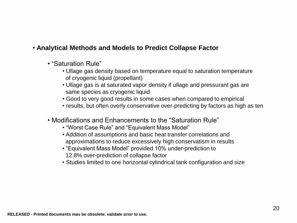
20
• Analytical Methods and Models to Predict Collapse Factor
• “Saturation Rule”• Ullage gas density based on temperature equal to saturation temperature
of cryogenic liquid (propellant)
• Ullage gas is at saturated vapor density if ullage and pressurant gas are
same species as cryogenic liquid
• Good to very good results in some cases when compared to empirical
• results, but often overly conservative over-predicting by factors as high as ten
• Modifications and Enhancements to the “Saturation Rule”• “Worst Case Rule” and “Equivalent Mass Model”
• Addition of assumptions and basic heat transfer correlations and
approximations to reduce excessively high conservatism in results
• “Equivalent Mass Model” provided 10% under-prediction to
12.8% over-prediction of collapse factor
• Studies limited to one horizontal cylindrical tank configuration and size
RELEASED - Printed documents may be obsolete; validate prior to use.

21
• Analytical Methods and Models to Predict Collapse Factor
(Continued)
• Semi-Empirical Curve-Fit Models
• A single equation or simultaneous set of equations
• Ullage gas, incoming pressurant gas, propellant temperature, and tank wall
properties used in equations(s)
• Constants and exponents derived from empirical data developed and used
in equation(s)
• Model presented in two studies, Epstein and Anderson (1968) and
Epstein (1965), had collapse factor prediction errors below 12%, most errors
around 5 to 6%
• Enhancements made, VanDresar (1995), to models from above two studies
• Equivalent dimension parameters developed for spherical and oblate
spheroid tanks
• Revised constants for liquid hydrogen propellant expulsions
• Methods added to adjust for cases with initial ullage volumes <20%,
large final propellant volumes, and internal tank hardware
RELEASED - Printed documents may be obsolete; validate prior to use.

22
• Analytical Methods and Models to Predict Collapse Factor (Continued)
• Upper and Lower Bound Analyses
• Developed in mid-1980’s though early 1990’s
• Major focus to evaluate pressurant gas requirements (collapse factors) at
supercritical and high subcritical tank pressures
• Accomodate no distinction between liquid and gas phases or
possibility of two-phase region
• Upper bound based on complete mixing of all fluids in tank
• Lower bound based on separate ullage gas and cryogenic propellant
regions with no heat or mass transfer at boundaries (except where
pressurant gas enters the ullage and cryogenic propellant is discharged)• Ullage-gas-to-propellant interface modeled as horizontal plane
• Empirical collapse factor data always fell between the upper and lower
bound collapse factor data (but this was often a very wide range)
• Lumped Mass Fluid Region (LMFR) Models(presented on following slides)
• Multiple Discrete Fluid Segment (MDFS) Models(presented on slides that follow those for LMFR Models)
RELEASED - Printed documents may be obsolete; validate prior to use.

2323
Reference Citation
Heat Transfer Mass Transfer
Model Errors Compared to Empirical Data Ullage Gas to Wall Propellant to Wall Ullage Gas to Propellant External Tank Wall Ullage Gas to Propellant 12 NLC, Correlation for Conv. H.T.
Coeff. not provided Based on H.T. from wall boiling liquid propellant
Not Discussed NLC, Correlation for Conv. H.T. Coeff. not shown
Not Discussed Range: -9.6 to 7.8%; Mean: 1.11%; Std. Dev. 5.0%; 10 Tests Compared
14 NLC, NC, Note 7 Assumed Negligible Assumed Negligible Not Discussed Assumed No Mass Transfer Range: -10.4 to 18.5%; Mean: 0.65%; Std. Dev. 7.74%; 18 Tests Compared
33 NLC, NC, Note 9 Assumed Negligible Not Modeled Modeled as Adiabatic Determined from Empirical Data Range: -9.0 to 8.4%; Mean: 0.34%; Std. Dev. 4.57%; 12 Tests Compared
79 NLC, NC, VP & HP [Ref. 87 Correlations]
NLC, NC, VP & HP [Ref. 87 Correlations]
NLC, NC, HPCSU [Ref. 87 Correlations]
Modeled as Adiabatic Assumed Negligible Pressurant gas supply bottle press. And temp. show < 1 K and <0.5 MPa error for part of Test 74 on E-8 Test Stand
80 NLC, NC & FC, Notes 3 and 5 [Ref. 34 Corrrelations]
Assumed Negligible NLC, NC & FC, Notes 3 and 6 [Ref. 34 Correlations]
Modeled as Adiabatic, Note 5
None, equivalent mass transfer modeled by added H.T., Note 6
No comparisons presented; model predicts Collapse Factor of 1.20 to 1.24
88 Notes 1 and 3 Note 2 Note 4 Note 1 Note 1 Range: -9.3 to 13.1%; Mean: 2.75%; Std. Dev. 5.74%; 11 Tests Compared
89 NLC, NC NLC, NC Not Discussed Not Discussed Not Discussed ~10 to 12% estimated from UG Press. & Temp. data
90 NLC, NC, HPCSD EC NLC, NC, HPCSU Not Discussed Not Discussed ~18 to 30% based on comparison with model data in Epstein and Anderson (1968)
91 NLC, NC, Note 7 Assumed Negligible NLC, NC, HPCSU [from Ref. 92] Not Discussed (1) and (2) -14.1, 4.7, -1.8, 0% for GH over LH; -2.5, -8.7, 6.7, -2.5% for GHe over LH
92 NLC,NC, VP & FC NLC,NC, VP & HP, FC NLC,NC, HPCSU NLC, FC & Radiation (1), (6), and Note 8 No Comparisons Presented
Key: NLC = Newton's Law of Cooling NC = Natural (Free) Convection FC = Forced Convection HP = Horizontal Plate (Natural Convection Correlations) HPCSD = Horizontal Plate (Natural Convection Correlations), Cold Side Down HPCSU = Horizontal Plate (Natural Convection Correlations), Cold Side Up VP = Vertical Plate (Natural Convection Correlations) EC = Equivalent Conduction; thermal conductivity and slope of temperature gradient across finite segment/element at boundary (1) = First Mass Transfer Computation Technique, from "Mass Transfer Correlations" section of Chapter II of Ref. 3
(2) = Second Mass Transfer Computation Technique, from "Mass Transfer Correlations" section of Chapter II of Ref. 3 (6) = Sixth Mass Transfer Computation Technique, from "Mass Transfer Correlations" section of Chapter II of Ref. 3
Notes: 1. An energy balance equation using propellant, mean ullage gas, entering pressurant gas, and tank wall temperatures; temp erature differentials; and empirically determined coefficients is used to calculate rate of change of ullage gas temperature at discrete time steps.
2. A condensation or evaporation energy balance equation, whichever has highest magnitude, using propellant, mean ullage g as, and tank wall temperatures; temperature differentials; and empirically determined coefficients is used to calculate rate of change of liquid propellant temperature at discrete time ste ps.
3. Ullage gas is divided into two regions; the lower region contains only the initial mass of ullage gas prior to entry of pressurant gas and the upper region contains only pressurant gas supplied from external source.
4. External tank heating is assumed to heat and evaporate liquid propellant only. Evaporation rate of propel lant is calculated from heat transfer equation using tank wall and liquid propellant temperatures, heat transfer areas, latent heat of vaporization, and empirically determined coefficients.
5. To simulate effects of transient and non-uniform temperatures through thick tank walls, the wall is modeled as having uniform temperature through 70% of the actual wall thickness wher e heat is transferred from the ullage gas; 30% of the wall thickness is modeled as thermally isolated from remianing wall.
6. 740 BTU/hr-ft2-R for GH over LH and 520 BTU/hr-ft2-R for GN over LOX added to calculated convective heat transfer coefficient from Ref. 34 correlations to simulate effects of m ixing between ullage gas and cryogenic propellant; these resulted in approximate 10% increase in required pressurant gas.
7. Ullage gas modeled as having linear vertical temperature profile with temperature at top of region equal to entering pre ssurant gas temperature and temperature at bottom of region equal to saturation temperature of propellant; Mean ullage gas temperature used to calculate heat transfer at ullage gas boundaries with tank wall is av erage of temperatures at top and bottom of ullage gas region.
8. During rapid change in tank pressure, mass transfer across ullage-gas-to-cryogenic-propellant interface is product of ullage volume and ullage gas density change based on net difference between new tank pressure and propellant saturation pressure.
9. Natural convection correlation used with time of pressurant gas entry, thermal properties of ullage gas and tank wall, tank wall thickness and inside diameter to compute ratio of actual to maximum total heat in tank wall; Maximum total heat in tank wall is when all of tank wall is at temperature of the incoming p ressurant gas; Coefficients and exponents in the correlation to compute ratio of actual to maximum total heat in tank wall are derived from curvefits of empirical data.
Table 6 Summary Data for Lumped Mass Fluid Region (LMFR) Models
1962
1965
1992
1962
1989
1961
1967
1998
1964
1964
Year
RELEASED - Printed documents may be obsolete; validate prior to use.

24
Modeling the Cryogenic Propellant Tank System; the Higher Fidelity
Multiple Discrete Fluid Segment (MDFS) Models
Subdivide ullage gas into discrete
vertically stacked segments to model
vertical temperature distribution
Subdivide upper portion of cryogenic
propellant region where most of
vertical temperature gradient is
expected
Variation of temperature in horizontal or
radial direction limited to small boundary
layer near the tank wall
24
RELEASED - Printed documents may be obsolete; validate prior to use.

2525
Reference Citation
Heat Transfer Mass Transfer
Model Errors Compared to Empirical Data
Ullage Gas to Wall
Propellant to Wall
Ullage Gas to Propellant
Intra-Ullage-Gas Segment-to-Segment
Intra-Propellant Segment-to-
Segment External Tank
Wall Ullage Gas to
Propellant
Intra-Ullage-Gas Segment-to-
Segment
3 NLC, NC & FC NLC, NC NLC, NC, FC EC & EFC EC Adiabatic Outer Wall
Modeled
N/A, Assumed to be Zero
No Mass Transfer other than
Pressurant Gas Entry
-13.0 to +1.0% for Test 004A +2.9 to +14.0% for Test 0027A -2.7 to +9.1% for Test 0029B
17 and 18 NLC, NC N/A, No Heat Transfer Assumed
NLC, NC (Same correlation as
Ref. 91)
EC N/A, Uniform Propellant Region
Modeled
Adiabatic Outer Wall Modeled
(1) No Mass Transfer other than
Pressurant Gas Entry
Range: -2.73 to 19.48%; Mean: 5.29%; Std. Dev.: 5.56%; 19 Tests Compared
23 NLC, NC NLC, NC EC EC EC NLC, NC, Note 2 (1) (6) <5%
30 NLC, NC N/A, No Heat Transfer Assumed
NLC, NC N/A, No Heat Transfer Assumed
N/A, Uniform Propellant Region
Modeled
Input Heat Flux N/A, Assumed to be Zero
No Mass Transfer other than
Pressurant Gas Entry
Range: -8.23 to 12.04%; Mean: 2.22%; Std. Dev.: 6.05%; 10 Tests Compared
34 NLC, NC & FC NLC, NC NLC, NC & FC EC EC NLC, NC & Radiation, Note
1
(6) (6) Range: Approx. -30 to 12%; Mean: 0.1 to 2.3%; Std. Dev.: 10.9 to 8.5%; 11 Tests Compared
93 No Heat Transfer Assumed
EC EC (liquid side only)
N/A EC Input Heat Flux (1) N/A; Ullage Gas at Uniform Temp.
No Comparisons Presented
94 NLC, NC & FC NLC, NC NLC, NC & FC EC EC NLC, NC & Radiation, Note
1
(1) and (6) (6) Comparisons not presented; ~10% Max. Cumulative Error; ~20% Max. Instantaneous Error from Nein and Thompson (1966)
95 NLC, NC & FC NLC, NC NLC, NC & FC EC EC Unknown (1) Unknown ~10% for Test 130-9; ~10 to 12% for Test 130-6; ~5% for Test 6E
96 NLC, NC & FC No Heat Transfer Assumed
NLC, NC (Same correlation as
Ref. 91)
EC N/A, Uniform Propellant Region
Modeled
Input Heat Flux Not Discussed No Mass Transfer other than
Pressurant Gas Entry
0.5 to 16.0% Error for Tank Pressurization; 7.0 to 12.4% Error for Propellant Expulsion
Key:
NLC = Newton's Law of Cooling
NC = Natural (Free) Convection; Ref. 34 correlations unless noted otherwise
FC = Forced Convection; correlation presented in "Combined Natural and Forced Convection Correlations" section
EC = Equivalent Conduction; thermal conductivity and slope of temperature gradient across finite segment/element at boundary
EFC = Equivalent Forced Convection (and Mixing); similar to correlation presetned in "Combined Natural and Forced Convection Correlations" section
(1) = First Mass Transfer Computation Technique, from "Mass Transfer Correlations" Section of Chapter II in Ref. 3
(6) = Sixth Mass Transfer Computation Technique, from "Mass Transfer Correlations" Section of Chapter II in Ref. 3
Notes:
1. Equivalent conductance based on natural convection and radiation heat transfer is used; this parameter is calculated from equation using empirically derived constants, bottle wall temperature and ambient air temperature, and these temperatures raised to the fourth power
2. Equivalent conductance based on natural convection only; correlation not presented
Table 7 Summary Data for Multiple Discrete Fluid Segment (MDFS) Models
2009
1988
1970
1965
1966
1992
1963
1974
1965
Year
The MDFS Models had Errors Comparable to LMFR Models, but the MDFS Models Covered
Wider Range of Tank Sizes, Pressures, and Expulsion Flow Rates
RELEASED - Printed documents may be obsolete; validate prior to use.

26
Summary
• Wide Range of Empirical Collapse Factors; 0.87 to 10.34
(Cannot directly apply empirical data to all cases without
understanding parameters that cause the wide variations)
• For Majority of Cases, Empirical Collapse Factor Data at
Low Subcritical Operating Pressures
• For Some Cases, Empirical Collapse Factor Data at
Supercritical & High Subcritical Operating Pressures
• Significant Effects on Collapse Factors; Pressurant Gas Entry
Velocity Vectors into Ullage which Drive Heat Transfer Rates
at Ullage Gas Region Boundaries, Ullage Gas Vertical
Temperature Gradients, Mass Transfer between Ullage Gas
and Propellant Regions
• Many Types of Analytical Models for Collapse Factor Prediction
• MDFS (Multiple Discrete Fluid Segment) Models Provide best
Predictions over Full Range of Operating Conditions
RELEASED - Printed documents may be obsolete; validate prior to use.