
A Guide for Power Factor Testing Instrument Transformers ...
35
© OMICRON Page 1 of 35 Application Guide A Guide for Power Factor Testing Instrument Transformers: CCVTs, PTs, and CTs Revision #1 - April 2019 Contributors Charles Sweetser | [email protected] Brandon Dupuis | [email protected] Logan Merrill | [email protected] Ben Clark | [email protected] Copyrighted 2019 by OMICRON electronics Corp USA All rights reserved. No part of this guide may be reproduced or transmitted in any form or by any means, electronic or mechanical, including photocopying, recording, or any information storage or retrieval system or method, now known or hereinafter invented or adopted, without the express prior written permission of OMICRON electronics Corp USA.
Transcript of A Guide for Power Factor Testing Instrument Transformers ...
© OMICRON Page 1 of 35
Application Guide
A Guide for Power Factor Testing Instrument Transformers:
CCVTs, PTs, and CTs
Revision #1 - April 2019 Contributors Charles Sweetser | [email protected] Brandon Dupuis | [email protected] Logan Merrill | [email protected] Ben Clark | [email protected]
Copyrighted 2019 by OMICRON electronics Corp USA All rights reserved. No part of this guide may be reproduced or transmitted in any form or by any means, electronic or mechanical, including photocopying, recording, or any information storage or retrieval system or method, now known or hereinafter invented or adopted, without the express prior written permission of OMICRON electronics Corp USA.

© OMICRON 2019 Page 2 of 35
Contents
1 Introduction ............................................................................................................................................3
2 CCVT Introduction .................................................................................................................................3 2.1 Typical CCVT Construction (for CCVT Models with an Inaccessible Potential Terminal) .............4 2.2 The Carrier Terminal .......................................................................................................................5 2.3 The Potential Terminal ....................................................................................................................6
3 CCVT Power Factor Testing .................................................................................................................6 3.1 CCVT with an Inaccessible Potential Terminal - Single-Unit Stack ...............................................6
3.1.1 C1 and C2 Series Measurement (recommended) ............................................................................ 7 3.1.2 C2 Measurement (recommended) .................................................................................................... 8 3.1.3 C1 Measurement (recommended) .................................................................................................... 9
3.2 CCVT with an Inaccessible Potential Terminal - Two-Unit Stack ................................................ 10 3.2.1 C1 and C2 Series Measurement (recommended) .......................................................................... 12 3.2.2 C2 Measurement (recommended) .................................................................................................. 13 3.2.3 C1-1 Measurement (recommended) ............................................................................................... 14 3.2.4 C1-2 Measurement (recommended) ............................................................................................... 15 3.2.5 C1-1 and C1-2 Series Measurement (optional) .............................................................................. 17 3.2.6 C1-1 and C2 Series Measurement (optional) .................................................................................. 18
3.3 CCVT with an Accessible Potential Terminal - Single-Unit Stack ............................................... 19 3.4 CCVT with an Accessible Potential - Two-Unit Stack ................................................................. 20
4 CCVT Ratio Test.................................................................................................................................. 21
5 CCVT Testing Examples .................................................................................................................... 23 5.1.1 Example 1: Trench TEIRF 115kV (2009) ........................................................................................ 23 5.1.2 Example 2: Alstom Type OTCF-300 (2012) .................................................................................... 25
6 HVCT Power Factor Testing .............................................................................................................. 27 6.1 HVCT Power Factor for HVCTs without Test Taps ..................................................................... 27 6.2 HVCT Power Factor for HVCTs with Test Taps .......................................................................... 28
7 Potential Transformer Power Factor Testing .................................................................................. 30 7.1 Potential Transformers where both primary terminals are accessible, and can be isolated from ground ................................................................................................................................................... 30 7.2 Potential Transformers where one of the two primary terminals CANNOT be isolated from ground ..................................................................................................................................................... 32 7.3 3-Phase Potential Transformers where the neutral bushing terminal is accessible, and can be isolated from ground ............................................................................................................................. 34
8 References .......................................................................................................................................... 35
9 Support Resources ............................................................................................................................ 35

© OMICRON 2019 Page 3 of 35
1 Introduction
The following information is intended to provide the reader with a basic introduction to performing Power Factor tests on Instrument Transformers. This is not an exhaustive resource, and does not include advanced troubleshooting or test analysis. This is simply intended to guide the user through the testing process. The processes outlined in this guide are based on using the CP TD1 accessory with either a CPC 100 or a TESTRANO 600. However, these test procedures can be applied with any Power Factor test-instrument. For safety purposes, we recommend that the operator reads the user manual before using the equipment. Please exercise caution and observe all applicable safety standards when performing these tests. The following guide has been divided into sections, each representing a different type of Instrument Transformer. When testing a CCVT, if you are not sure which category the test-specimen falls into, please refer to the “CCVT Introduction” section to better identify which category it belongs to. If you are testing a CCVT, in most cases, you will be testing a “CCVT with an Inaccessible Potential Terminal”.
2 CCVT Introduction
Note, if the CCVT under test only has one “housing unit”, then it will have a total of two Capacitors (C1 and C2). If the CCVT under test has two “housing units”, then it will have a total of three Capacitors (C1-2, C1-1, and C2). C2: This is the bottom-most Capacitor of the CCVT. The C2 Capacitor is located below the C1-1 Capacitor, in the bottom-most housing unit of the CCVT (see Figure 1). C1-1: The C1-1 Capacitor is located directly above the C2 Capacitor, in the bottom-most housing unit of the CCVT (see Figure 1). Note, if you are testing a two-unit CCVT, then the C1-1 Capacitance (pF) value may not be indicated on the nameplate. C1-2: The C1-2 Capacitor is located directly above the C1-1 Capacitor. The C1-2 Capacitor is typically located in its own housing unit, directly above the bottom-most housing unit of the CCVT (see Figure 1). Note, if you are testing a two-unit CCVT, then the C1-2 Capacitance (pF) value may not be indicated on the nameplate. C1: The C1 Capacitance is the series capacitance of C1-1, C1-2, C1-3, etc. If the CCVT under test only has one housing unit, then only one Capacitor will comprise the C1 Capacitance. Note, if the CCVT under test has more than two housing units “in the stack”, then there may exist a C1-3 Capacitor, a C1-4 Capacitor, etc.
Figure 1: Two-Unit CCVT with an Inaccessible Potential Terminal

© OMICRON 2019 Page 4 of 35
2.1 Typical CCVT Construction (for CCVT Models with an Inaccessible Potential Terminal)
Figure 2: Typical Alstom OTCF CCVT Wiring Diagram
Figure 3: Typical Trench CCVT Wiring Diagram (with carrier accessories)

© OMICRON 2019 Page 5 of 35
2.2 The Carrier Terminal
The Carrier Terminal, which is typically located in the base box (aka junction box) of the CCVT, is critical for the CCVT Power Factor measurement.
• For the “older style” of CCVTs with accessible Potential Terminals (e.g. General Electric and Westinghouse CCVTs), the Carrier Terminal can typically be disconnected and isolated for testing.
• For modern CCVTs, the Carrier Terminal (often referred to as the “HF terminal”) is typically located
in the base box of the CCVT, and may need to be disconnected from ground-potential, from the drain coil, and/or from accessory leads. The following two Figures demonstrate where to find the Carrier Terminals for a Trench TEIRF 115kV CCVT and an Alstom Type OTCF-300 CCVT, respectively.
Figure 4: Trench and Alstom CCVT Baseboxes (showing Carrier/HF Terminal)
2.3 The Potential Terminal
The test procedure for performing a Power Factor measurement on a CCVT is largely dictated by if the CCVT has an accessible Potential Terminal.
• For the “older style” of CCVTs (e.g. General Electric and Westinghouse CCVTs), the Potential Terminal is typically accessible.
• For modern CCVTs, the Potential Terminal is typically NOT accessible, and CANNOT be accessed for Power Factor measurements. Typically, Trench and Alstom CCVTs fall under this category.
Carrier Terminal Carrier Terminal Trench TEIRF 115kV Alstom Type OTCF-300

© OMICRON 2019 Page 6 of 35
3 CCVT Power Factor Testing
3.1 CCVT with an Inaccessible Potential Terminal - Single-Unit Stack
The procedure for testing a single housing unit CCVT with an inaccessible Potential Terminal is provided in this section. The Trench TEIRF 115kV CCVT (shown in the following Figure) is an example of a single housing unit without an accessible Potential Terminal. For a single housing unit CCVT, there are typically only two individual capacitors, C1 and C2, that can be tested. For this CCVT type, there are three recommended Power Factor measurements, which are summarized in the following Table. Please observe the following steps prior to executing Test #1:
✓ De-energize the CCVT unit ✓ Ground the metallic terminal(s) of the CCVT, to discharge any remaining energy within the
capacitors ✓ Disconnect and isolate the CCVT line-terminal from any bus, cable, support insulators, etc. ✓ Close the Potential ground switch and the Carrier ground switch (if applicable) ✓ Ensure that both the CCVT housing and the test-equipment are solidly bonded to earth-ground
potential ✓ Clean and dry the exterior surfaces of the CCVT’s housing units ✓ *Note, for the C2 measurement, the test-voltage should not exceed the voltage-rating of the Carrier
Terminal – If you are unsure, we recommend applying a test-voltage of 500V, for the C2 Test
Figure 5: Trench TEIRF 115kV CCVT
Table 1: Single-Unit CCVT with an Inaccessible Potential Terminal - Power Factor Test Plan
Test Measured
Capacitance Test Mode
Carrier Grounding
Switch
Potential Grounding
Switch
High Voltage
Lead
Low Voltage
Lead
Typical Test
Voltage
1 (recommended)
C1 and C2 Series Test
(Overall) UST-A Closed Open Line-Terminal
(Top of C1 Capacitor) Carrier
Terminal 10kV
2 (recommended)
C2 GSTg-A Closed Closed Carrier Terminal Line-Terminal
(Top of C1 Capacitor)
*500V
3 (recommended)
C1 GST Closed Closed Line-Terminal (Top of C1 Capacitor) - 10kV
Base Box
C1 and C2
Trench CCVT Type TEIRF 115kV Manufactured in 2009

© OMICRON 2019 Page 7 of 35
3.1.1 C1 and C2 Series Measurement (recommended)
The test procedure for the C1 and C2 series Power Factor measurement (aka the Overall Test) is provided in the following Table. Before executing the C1 and C2 series Power Factor measurement, please perform the following steps,
✓ Disconnect and isolate the Carrier from ground-potential, from the drain coil, and from any accessory leads (if applicable)
✓ The test voltage (typically 10kV) should not exceed the line-to-ground rating of the CCVT insulation ✓ Open the Potential ground switch
Table 2: Single-Unit CCVT with an Inaccessible Potential Terminal – C1 and C2 Series Test
Test Measured
Capacitance Test Mode
Carrier Grounding
Switch
Potential Grounding
Switch
High Voltage
Lead
Low Voltage
Lead
Typical Test
Voltage
1 (recommended)
C1 and C2 Series Test
(aka the Overall Test)
UST-A Closed Open Line-Terminal
(Top of C1 Capacitor)
Carrier Terminal 10kV
Figure 6: Single-Unit CCVT with an Inaccessible Potential – C1 and C2 Series Test Wiring Diagram
© OMICRON 2019 Page 8 of 35
3.1.2 C2 Measurement (recommended)
The test procedure for the C2 Power Factor measurement is provided in the following Table. Before executing the C2 Power Factor measurement, please perform the following steps,
✓ Leave the Carrier ground switch closed ✓ Disconnect and isolate the Carrier from ground-potential, from the drain coil, and from any
accessory leads (if applicable) ✓ Close Potential ground switch ✓ *Note, for the C2 measurement, the test-voltage should not exceed the voltage-rating of the Carrier
Terminal – If you are unsure, we recommend applying a test-voltage of 500V, for the C2 Test
Table 3: Single-Unit CCVT with an Inaccessible Potential Terminal – C2 Power Factor Test
Test Measured
Capacitance Test Mode
Carrier Grounding
Switch
Potential Grounding
Switch
High Voltage
Lead
Low Voltage
Lead
Typical Test
Voltage
2 (recommended)
C2 GSTg-A Closed Closed Carrier Terminal
Line-Terminal
(Top of C1 Capacitor)
*500V
Figure 7: Single-Unit CCVT with an Inaccessible Potential – C2 Power Factor Test Wiring Diagram

© OMICRON 2019 Page 9 of 35
3.1.3 C1 Measurement (recommended)
The test procedure for the C1 Power Factor measurement is provided in the following Table. Before executing the C1 Power Factor measurement, please perform the following steps,
✓ Reconnect the Carrier to ground-potential, to the drain coil, and to any accessory leads (if applicable)
✓ Both the Potential and Carrier ground switches should be closed ✓ The test voltage (typically 10kV) should not exceed the line-to-ground rating of the CCVT
Table 4: Single-Unit CCVT with an Inaccessible Potential Terminal – C1 Power Factor Test
Test Measured
Capacitance Test Mode
Carrier Grounding
Switch
Potential Grounding
Switch
High Voltage
Lead
Low Voltage
Lead
Typical Test
Voltage
3 (recommended)
C1 GST Closed Closed Line-Terminal
(Top of C1 Capacitor)
- 10kV
Figure 8: Single-Unit CCVT with an Inaccessible Potential Terminal – C1 Power Factor Wiring Diagram
© OMICRON 2019 Page 10 of 35
3.2 CCVT with an Inaccessible Potential Terminal - Two-Unit Stack
The procedure for testing a CCVT with an inaccessible Potential Terminal, and with a two-unit housing stack, is provided in the following section. The Alstom OTCF 300 CCVT (shown in the following Figure) is an example of a CCVT with a two-unit housing stack.
Figure 9: Alstom Type OTCF 300 CCVT
For this type of CCVT, there are typically three individual Capacitances (C2, C1-1, and C1-2). There are six possible Power Factor measurements (summarized in the following Table) that could be performed. Please observe the following steps prior to executing Test #1:
✓ De-energize the CCVT unit ✓ Ground the metallic terminal(s) of the CCVT, to discharge any remaining energy within the
capacitors ✓ Disconnect and isolate the CCVT line-terminal from any bus, cable, support insulators, etc. ✓ Close the Potential ground switch and the Carrier ground switch (if applicable) ✓ Ensure that both the CCVT housing and the test-equipment are solidly bonded to earth-ground
potential ✓ Clean and dry the exterior surfaces of the CCVT’s housing units ✓ *Note, for the C2 measurement, the test-voltage should not exceed the voltage-rating of the Carrier
Terminal – If you are unsure, we recommend applying a test-voltage of 500V, for the C2 Test

© OMICRON 2019 Page 11 of 35
Table 5: Two-Unit CCVT with an Inaccessible Potential Terminal - Power Factor Test Plan
Test Measured
Capacitance Test Mode
Carrier Grounding
Switch
Potential Grounding
Switch
High Voltage
Lead
Low Voltage
Lead
Typical Test
Voltage
1 (recommended)
C1 and C2 Series (Overall Test) UST-A Closed Open
Line-Terminal (Top of C1-2 Capacitor)
Carrier Terminal 10kV
2 (recommended)
C2 GSTg-A Closed Closed Carrier Terminal
Line-Terminal (Top of C1-2 Capacitor)
*500V
3 (recommended)
C1-1 GSTg-A Closed Closed Top of C1-1 Capacitor
Line-Terminal (Top of C1-2 Capacitor)
10kV
4 (recommended)
C1-2 UST-A Closed Closed Top of C1-1 Capacitor
Line-Terminal (Top of C1-2 Capacitor)
10kV
5 (optional) C1 (C1-1 and C1-2 Series) GST Closed Closed
Line-Terminal (Top of C1-2 Capacitor)
- 10kV
6 (optional) *C1-1 and C2 Series GSTg-A Closed Open Top of C1-1
Capacitor
Line-Terminal (Top of C1-2 Capacitor)
10kV
*Note, for measurement #6, the measured Power Factor % value may be abnormally high, abnormally low, or negative. This behavior is typical for measurement #6; therefore, for measurement #6, we recommend to not analyze the Power Factor % value. Instead, please only analyze the measured Current (mA) and Watt Losses (W).
© OMICRON 2019 Page 12 of 35
3.2.1 C1 and C2 Series Measurement (recommended)
The test procedure for the C1 and C2 series Power Factor measurement is provided in the following Table. Before executing the C1 and C2 series Power Factor measurement, please perform the following steps,
✓ Leave the Carrier ground switch closed ✓ Disconnect and isolate the Carrier Terminal from ground, from the drain coil, and from any
accessory leads (if applicable) ✓ Open the Potential grounding switch, for the C1 and C2 series measurement ✓ The test voltage (typically 10kV) should not exceed the line-to-ground voltage rating of the CCVT
Table 6: Two-Unit CCVT with an Inaccessible Potential Terminal - C1 and C2 Series Power Factor Test
Test Measured
Capacitance Test Mode
Carrier Grounding
Switch
Potential Grounding
Switch
High Voltage
Lead
Low Voltage
Lead
Typical Test
Voltage
1 (recommended)
C1 and C2 Series
(Overall Test) UST-A Closed Open
Line-Terminal (Top of C1-2 Capacitor)
Carrier Terminal 10kV
Figure 10: Two-Unit CCVT with an Inaccessible Potential Terminal - C1 and C2 Series Power Factor Test Wiring Diagram

© OMICRON 2019 Page 13 of 35
3.2.2 C2 Measurement (recommended)
The test procedure for the C2 Power Factor measurement is provided in the following Table. Before executing the C2 Power Factor measurement, please perform the following steps,
✓ Close the Potential grounding switch for the C2 measurement ✓ Leave the Carrier ground switch closed ✓ Disconnect and isolate the Carrier Terminal from the ground, from the drain coil, and from any
accessory leads (if applicable) ✓ *Note, for the C2 measurement, the test-voltage should not exceed the voltage-rating of the Carrier
Terminal – If you are unsure, we recommend applying a test-voltage of 500V, for the C2 Test
Table 7: Two-Unit CCVT with an Inaccessible Potential Terminal - C2 Power Factor Test
Test Measured
Capacitance Test Mode
Carrier Grounding
Switch
Potential Grounding
Switch
High Voltage
Lead
Low Voltage
Lead
Typical Test
Voltage
2 (recommended)
C2 GSTg-A Closed Closed Carrier Terminal
Line-Terminal (Top of C1-2 Capacitor)
*500V
Figure 11: Two-Unit CCVT with an Inaccessible Potential Terminal - C2 Power Factor Test Wiring Diagram
© OMICRON 2019 Page 14 of 35
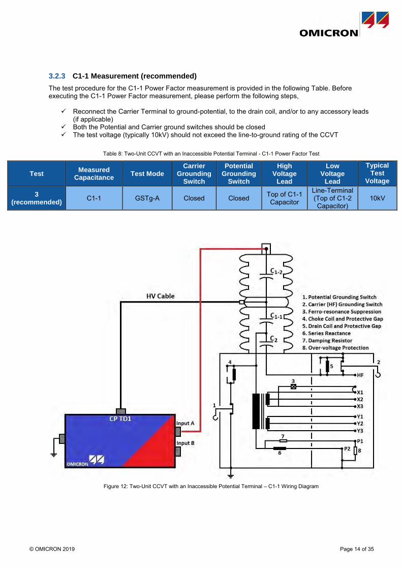
3.2.3 C1-1 Measurement (recommended)
The test procedure for the C1-1 Power Factor measurement is provided in the following Table. Before executing the C1-1 Power Factor measurement, please perform the following steps,
✓ Reconnect the Carrier Terminal to ground-potential, to the drain coil, and/or to any accessory leads (if applicable)
✓ Both the Potential and Carrier ground switches should be closed ✓ The test voltage (typically 10kV) should not exceed the line-to-ground rating of the CCVT
Table 8: Two-Unit CCVT with an Inaccessible Potential Terminal - C1-1 Power Factor Test
Test Measured
Capacitance Test Mode
Carrier Grounding
Switch
Potential Grounding
Switch
High Voltage
Lead
Low Voltage
Lead
Typical Test
Voltage
3 (recommended)
C1-1 GSTg-A Closed Closed Top of C1-1 Capacitor
Line-Terminal (Top of C1-2 Capacitor)
10kV
Figure 12: Two-Unit CCVT with an Inaccessible Potential Terminal – C1-1 Wiring Diagram
© OMICRON 2019 Page 15 of 35
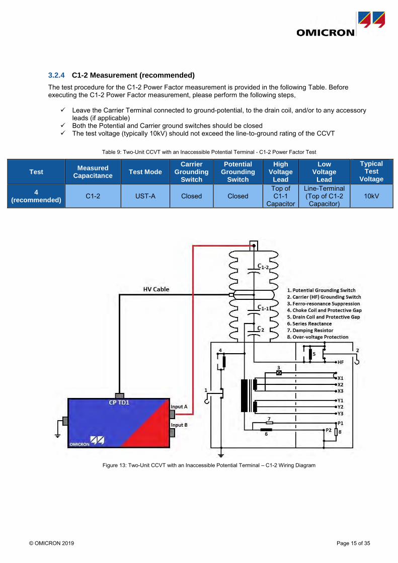
3.2.4 C1-2 Measurement (recommended)
The test procedure for the C1-2 Power Factor measurement is provided in the following Table. Before executing the C1-2 Power Factor measurement, please perform the following steps,
✓ Leave the Carrier Terminal connected to ground-potential, to the drain coil, and/or to any accessory leads (if applicable)
✓ Both the Potential and Carrier ground switches should be closed ✓ The test voltage (typically 10kV) should not exceed the line-to-ground rating of the CCVT
Table 9: Two-Unit CCVT with an Inaccessible Potential Terminal - C1-2 Power Factor Test
Test Measured
Capacitance Test Mode
Carrier Grounding
Switch
Potential Grounding
Switch
High Voltage
Lead
Low Voltage
Lead
Typical Test
Voltage
4 (recommended)
C1-2 UST-A Closed Closed Top of C1-1
Capacitor
Line-Terminal (Top of C1-2 Capacitor)
10kV
Figure 13: Two-Unit CCVT with an Inaccessible Potential Terminal – C1-2 Wiring Diagram

© OMICRON 2019 Page 16 of 35
3.2.5 C1-1 and C1-2 Series Measurement (optional)
The test procedure for the C1-1 and C1-2 series Power Factor measurement is provided in the following Table. Before executing the C1-1 and C1-2 series Power Factor measurement, please perform the following steps,
✓ Both the Potential and Carrier ground switches should be closed ✓ Leave the Carrier Terminal connected to ground-potential, to the drain coil, and/or to any accessory
leads (if applicable) ✓ The test voltage (typically 10kV) should not exceed the line-to-ground rating of the CCVT
Table 10: Two-Unit CCVT with an Inaccessible Potential Terminal - C1-1 and C1-2 Series Power Factor Test
Test Measured
Capacitance Test Mode
Carrier Grounding
Switch
Potential Grounding
Switch
High Voltage
Lead
Low Voltage
Lead
Typical Test
Voltage
5 (optional) C1 (C1-1 and C1-2 Series) GST Closed Closed
Line-Terminal (Top of C1-2 Capacitor)
- 10kV
Figure 14: Two-Unit CCVT with an Inaccessible Potential Terminal - C1-1 and C1-2 Series Test Wiring Diagram

© OMICRON 2019 Page 17 of 35
3.2.6 C1-1 and C2 Series Measurement (optional)
The test procedure for the C1-1 and C2 series Power Factor measurement is provided in the following Table. Before executing the C1-1 and C2 series Power Factor measurement, please perform the following steps,
✓ Leave the Carrier ground switch closed ✓ Leave the Carrier Terminal connected to ground-potential, to the drain coil, and/or to any accessory
leads (if applicable) ✓ Open the potential grounding switch for the C1-1 and C2 series measurement ✓ The test voltage (typically 10kV) should not exceed the line-to-ground rating of the CCVT
Table 11: Two-Unit CCVT with an Inaccessible Potential Terminal - C1-1 and C2 Series Test
Test Measured
Capacitance Test Mode
Carrier Grounding
Switch
Potential Grounding
Switch
High Voltage
Lead
Low Voltage
Lead
Typical Test
Voltage
6 (optional) *C1-1 and C2 Series GSTg-A Closed Open Top of C1-1
Capacitor
Line-Terminal (Top of C1-2 Capacitor)
10kV
*Note, for measurement #6, the measured Power Factor % value may be abnormally high, abnormally low, or negative. This behavior is typical for measurement #6; therefore, for measurement #6, we recommend to not analyze the Power Factor % value. Instead, please only analyze the measured Current (mA) and Watt Losses (W).
Figure 15: Two-Unit CCVT with an Inaccessible Potential Terminal - C1-1 and C2 Series Test Wiring Diagram

© OMICRON 2019 Page 18 of 35
3.3 CCVT with an Accessible Potential Terminal - Single-Unit Stack
The procedure for testing a single housing unit CCVT with an accessible Potential Terminal is provided in this section. For a single housing unit CCVT, there are typically only two individual capacitors, C1 and C2, that can be tested. For this CCVT type, there are three recommended Power Factor measurements, which are summarized in the following Table. Please observe the following steps prior to executing Test #1:
✓ De-energize the CCVT unit ✓ Ground the metallic terminal(s) of the CCVT, to discharge any remaining energy within the
capacitors ✓ Disconnect and isolate the CCVT line-terminal from any bus, cable, support insulators, etc. ✓ Close the Potential ground switch and the Carrier ground switch (if applicable) ✓ Ensure that both the CCVT housing and the test-equipment are solidly bonded to earth-ground
potential ✓ Clean and dry the exterior surfaces of the CCVT’s housing units ✓ For all three Power Factor measurements, both the Carrier and the Potential Terminals must be
disconnected and isolated from any drain coils, gaps, and/or accessory leads.
Table 12: Single-Unit CCVT with an Accessible Potential Terminal - Power Factor Test Plan
Test # Measured
Capacitance Test Mode
Carrier Grounding
Switch
Potential Grounding
Switch
High Voltage
Lead
Low Voltage
Lead
Potential Terminal
Typical Test
Voltage
1 (recommended)
C1 and C2 Series
(Overall Test) UST-A Closed Closed
Line-Terminal (Top of C1 Capacitor)
Carrier Terminal Floating 10kV
2 (recommended)
C1 UST-A Closed Closed Line-Terminal
(Top of C1 Capacitor)
Potential Terminal
Low Voltage
Lead 10kV
3 (recommended)
C2 UST-A Closed Closed Potential Terminal
Carrier Terminal
High Voltage
Lead 2kV

© OMICRON 2019 Page 19 of 35
3.4 CCVT with an Accessible Potential - Two-Unit Stack
For this type of CCVT, there are typically three individual Capacitances (C2, C1-1, and C1-2). There are six possible Power Factor measurements (summarized in the following Table) that could be performed. Please observe the following steps prior to executing Test #1:
✓ De-energize the CCVT unit ✓ Ground the metallic terminal(s) of the CCVT, to discharge any remaining energy within the
capacitors ✓ Disconnect and isolate the CCVT line-terminal from any bus, cable, support insulators, etc. ✓ Close the Potential ground switch and the Carrier ground switch (if applicable) ✓ Ensure that both the CCVT housing and the test-equipment are solidly bonded to earth-ground
potential ✓ Clean and dry the exterior surfaces of the CCVT’s housing units ✓ For all six Power Factor measurements, both the Carrier and the Potential Terminals must be
disconnected and isolated from any drain coils, gaps, and/or accessory leads.
Table 13: Two-Unit CCVT with an Accessible Potential Terminal - Power Factor Test Plan
Test # Measured
Capacitance Test
Mode
Carrier Grounding
Switch
Potential Grounding
Switch
High Voltage
Lead
Low Voltage
Lead Ground
Potential Terminal
Carrier Terminal
Typical Test
Voltage
1 Recommended
C1 and C2 Series
(Overall Test) UST-A Closed Closed
Line-Terminal
(Top of C1-2 Capacitor)
Carrier Terminal - Float
Low Voltage
Lead 10kV
2
Recommended C1-2 GSTg-A Closed Closed Top of C1-1 Capacitor
Potential Terminal
Top of C1-2
Capacitor
Low Voltage Lead Float 10kV
3
Recommended C1-1 UST-A Closed Closed Top of C1-1 Capacitor
Potential Terminal
Top of C1-2
Capacitor
Low Voltage Lead Float 10kV
4
Recommended C2 UST-A Closed Closed Potential Terminal
Carrier Terminal
Top of C1-2
Capacitor
High Voltage
Lead
Low Voltage
Lead 2kV
5 optional
C1-1 and C2 Series UST-A Closed Closed Top of C1-1
Capacitor Carrier
Terminal
Top of C1-2
Capacitor Float
Low Voltage
Lead 10kV
6 optional
C1 (C1-1 and C1-2 Series) GSTg-A Closed Closed Potential
Terminal Carrier
Terminal
Top of C1-2
Capacitor
High Voltage
Lead
Low Voltage
Lead 2kV

© OMICRON 2019 Page 20 of 35
4 CCVT Ratio Test
This section provides the test procedure for performing a Ratio Test (aka the Turns-Ratio Test) on a CCVT. Although the test-plan outlined in this section focuses on applying the OMICRON CPC 100, the test-plan can be adapted for other test-instruments. Before the Ratio Test is performed, please observe the following steps,
✓ Open the Potential grounding switch for the duration of the Ratio measurement. If the CCVT has an accessible Potential Terminal, please note that the Potential Terminal must remain connected to any “in-service” leads when the Ratio measurement is performed.
✓ Close the Carrier grounding switch for the duration of the Ratio measurement. If the CCVT has an accessible Carrier Terminal, please note that the Carrier Terminal must remain connected to any “in-service” leads (e.g. the drain coil, any protective gaps, etc…) when the Ratio measurement is performed.
✓ The test-voltage for the Ratio Test should not exceed the line-to-ground rating of the CCVT. Typically, a test-voltage of 2kV is applied for the CCVT Ratio Test.
Table 14: CCVT Ratio Test Test-Plan
Test #
Measurement Carrier
Grounding Switch
Potential Grounding
Switch
2kV Red Lead
2kV Black Lead
V1 AC Red Lead
V1 AC Black Lead
All Other Secondary Terminals
Typical Test
Voltage
1 X1-X3 Ratio Closed Open
Line-Terminal
(Top of C1 Capacitor)
Basebox Case of CCVT
X1 X3 (and ground X3) Float 2kV
2 X1-X2 Ratio Closed Open
Line-Terminal
(Top of C1 Capacitor)
Basebox Case of CCVT
X1 X2 (and ground X2) Float 2kV
3 Y1-Y3 Ratio Closed Open
Line-Terminal
(Top of C1 Capacitor)
Basebox Case of CCVT
Y1 Y3 (and ground Y3) Float 2kV
4 Y1-Y2 Ratio Closed Open
Line-Terminal
(Top of C1 Capacitor)
Basebox Case of CCVT
Y1 Y2 (and ground Y2) Float 2kV
Figure 16: Single-Unit CCVT Ratio Test - Connection Diagram for Measurement #1

© OMICRON 2019 Page 21 of 35
Figure 17: Single-Unit CCVT Ratio Test - Connection Diagram for Measurement #2
Figure 18: Single-Unit CCVT Ratio Test - Connection Diagram for Measurement #3
Figure 19: Single-Unit CCVT Ratio Test - Connection Diagram for Measurement #4

© OMICRON 2019 Page 22 of 35
5 CCVT Testing Examples
Note, all the examples provided in this section are of CCVTs with inaccessible Potential Terminals.
5.1.1 Example 1: Trench TEIRF 115kV (2009)
Figure 20: Trench TEIRF 115kV CCVT
Figure 21: Nameplate Capacitance of Trench TEIRF 115kV CCVT
Base Box
C1 and C2
Trench CCVT Type TEIRF 115kV Manufactured in 2009

© OMICRON 2019 Page 23 of 35
Figure 22: Nameplate Stack Capacitance of Trench TEIRF 115kV CCVT
Table 15: Power Factor Results for Example 1
Test # Measurement Measured Power
Factor Measured Capacitance Nameplate Capacitance
1 C2 0.08% 120,788pF 120,647pF
2 C1 0.07% 24,193pF 24,184pF
3 C1 and C2 Series Test 20,155pF (Calculated) 20,146pF
Table 16: Ratio Results for Example 1
Test Measurement Nameplate Ratio Measured Ratio Ratio Deviation
1 X1-X3 Ratio 3.332 3.341 -0.27%
2 X1-X2 Ratio - - -
3 Y1-Y3 Ratio 3.332 3.344 -0.36%
4 Y1-Y2 Ratio - - -

© OMICRON 2019 Page 24 of 35
5.1.2 Example 2: Alstom Type OTCF-300 (2012)
Figure 23: Alstom Type OTCF 300 CCVT
Figure 24: Nameplate of Alstom Type OTCF 300 CCVT
Base Box
C1-1 and C2
C1-2
Alstom Type OTCF 300 Manufactured in 2012

© OMICRON 2019 Page 25 of 35
Figure 25: Capacitor Stack Nameplate of Alstom Type OTCF 300 CCVT
Table 17: Power Factor Results for Example 2
Test Measured
Capacitance Measured
Power Factor Nameplate
Power Factor Measured
Capacitance Nameplate Capacitance
1 C2 0.12% - 56,469pF 56,100pF
2 C1-1 0.14% - 10,209pF -
3 C1-2 0.17% 0.09% 8,723pF 8,711pF (Not Shown in Pictures)
4 (optional) C1 (C1-1 and C1-2 Series) - - 4,703pF
(Calculated) 4,690pF
5 (optional) C1-1 and C2 Series - - - -
6 (optional) C1 and C2 Series - - 4,341pF (Calculated) 4,150pF
Table 18: Ratio Results for Example 2
Test Measurement Nameplate Ratio Measured Ratio Ratio Deviation
1 X1-X3 Ratio 1.333 1.337 -0.11%
2 X1-X2 Ratio - - -
3 Y1-Y3 Ratio 1.333 1.337 -0.11%
4 Y1-Y2 Ratio - - -

© OMICRON 2019 Page 26 of 35
6 HVCT Power Factor Testing
6.1 HVCT Power Factor for HVCTs without Test Taps
The following section provides the test procedure for performing a Power Factor measurement on a high-voltage current transformer that does not have a test tap. Before executing the Power Factor measurement, please perform the following,
✓ De-energize the HVCT unit ✓ Ground all the accessible primary terminal(s) of the HVCT, to discharge any remaining stored
energy ✓ Disconnect and isolate the HVCT’s primary terminal(s) from any bus, cable, support insulators, etc. ✓ Short-circuit the primary terminals of the HVCT (e.g. short-circuit H1 and H2, or H1 and H0) ✓ Completely isolate all secondary terminals of the HVCT from any external connections ✓ Ground one terminal on each secondary winding of the HVCT before executing the Power Factor
measurement ✓ Note, all other terminals on the secondary winding(s) (that are not grounded) should be open-
circuited (i.e. floating) for the duration of the Power Factor measurement The test procedure for performing a Power Factor measurement on an HVCT that does not have a test tap is provided in the following Table.
Table 19: Power Factor Test Plan for an HVCT that does not have a Test Tap
Test Mode Primary Terminals X1 Y1 Z1
X2, X3, Xn Y2, Y3, Yn Z2, Z3, Zn
#1 (Overall Test) GST Energize Ground Float
The recommended test-voltage for a Power Factor measurement on an HVCT that does not have a test tap is provided in the following Table.
Table 20: Recommended Test-Voltage for a Power Factor Measurement Performed on an HVCT that does not have a Test Tap
Test Oil-Filled < 15kV
Oil-Filled > 15kV
Dry-Type < 15kV
Dry-Type > 15kV
#1 (Overall Test) HVCT Line-to-Ground
Voltage Rating 10kV 2kV,
HVCT Line-to-Ground Voltage Rating, and 125% of the HVCT Line-to-Ground Voltage Rating
2kV and 10kV
Figure 26: Wiring Diagram for a Power Factor Measurement Performed on an HVCT that does not have a Test Tap

© OMICRON 2019 Page 27 of 35
6.2 HVCT Power Factor for HVCTs with Test Taps
The following section provides the test procedure for performing a Power Factor measurement on a high-voltage current transformer that has a test tap. Before the Power Factor measurement is performed, please perform the following,
✓ De-energize the HVCT unit ✓ Ground all the accessible primary terminal(s) of the HVCT, to discharge any remaining stored
energy ✓ Disconnect and isolate the HVCT’s primary terminal(s) from any bus, cable, support insulators, etc. ✓ Short-circuit the primary terminals of the HVCT (e.g. short-circuit H1 and H2, or H1 and H0) ✓ Completely isolate all secondary terminals of the HVCT from any external connections ✓ Ground one terminal on each secondary winding of the HVCT before executing the Power Factor
measurement ✓ Note, all other terminals on the secondary winding(s) (that are not grounded) should be open-
circuited (i.e. floating) for the duration of the Power Factor measurement The test procedure for performing a Power Factor measurement on an HVCT that has a test tap, is provided in the following Table.
Table 21: Power Factor Test Plan for an HVCT that has a Test Tap
Test Type Mode Primary
Terminals Tap Terminal
X1 Y1 Z1
X2, X3, Xn Y2, Y3, Yn Z2, Z3, Zn
#1 Overall GST Energize Tap-Cap On (i.e. Connected) Ground Float
#2 CHL GSTg-A Energize Red-A Lead Ground Float
#3 C1 UST-A Energize Red-A Lead Ground Float
#4 C2 GSTg-A Red-A Lead Energize Ground Float
The recommended test-voltages for Power Factor measurements performed on an HVCT that has a test tap, are provided in the following Table.
Table 22: Recommended Test-Voltages for Power Factor Measurements Performed on an HVCT that has a Test Tap
Test Oil-Filled < 15kV
Oil-Filled > 15kV
Dry-Type < 15kV
Dry-Type > 15kV
#1, #2, and #3 HVCT Line-to-Ground
Voltage Rating 10kV 2kV,
HVCT Line-to-Ground Voltage Rating, and 125% of the HVCT Line-to-Ground Voltage Rating
2kV and 10kV
#4 500V

© OMICRON 2019 Page 28 of 35
Figure 27: Wiring Diagram for Measurement #1 - For an HVCT that has a Test Tap
Figure 28: Wiring Diagram for Measurements #2 and #3 - For an HVCT that has a Test Tap
Figure 29: Wiring Diagram for Measurement #4 - For an HVCT that has a Test Tap

© OMICRON 2019 Page 29 of 35
7 Potential Transformer Power Factor Testing
7.1 Potential Transformers where both primary terminals are accessible, and can be isolated from ground
The following section provides the test procedure for performing a Power Factor measurement on a potential transformer where both primary terminals are accessible and can be isolated from ground. If the potential transformer under test has a primary terminal that is NOT accessible, or CANNOT be isolated from ground, then please refer to Section 7.2. Before the Power Factor measurement is performed, please perform the following steps,
✓ De-energize the PT unit ✓ Ground all the accessible primary terminal(s) of the PT, to discharge any remaining stored energy ✓ Disconnect and isolate the PT’s primary terminal(s) from any bus, cable, support insulators, etc. ✓ Short-circuit the primary terminals of the PT (e.g. short-circuit H1 and H2, or H1 and H0) ✓ Remove all ground connections from the primary terminals ✓ Completely isolate all secondary terminals of the PT from any external connections ✓ Ground one terminal on each secondary winding of the PT before executing the Power Factor
measurement ✓ Note, all other terminals on the secondary winding(s) (that are not grounded) should be open-
circuited (i.e. floating) for the duration of the Power Factor measurement The test procedure for performing a Power Factor measurement on a PT where both primary terminals are accessible and can be isolated from ground, is provided in the following Table.
Table 23: Power Factor test plan for a PT where both primary terminals are accessible and can be isolated from ground
Test Type Mode H1 H2 (or H0) X1 Y1 Z1
X2, X3, Xn Y2, Y3, Yn Z2, Z3, Zn
#1 Overall Test GST Energize (while H1-H2 or H1-H0 is Short-Circuited) Ground Float
#2 H1 Winding-to-Ground
Insulation Test GSTg-A Energize Red-A Lead Ground Float
#3 *Excitation Test UST-A Energize Red-A Lead Ground Float
#4 H2 Winding-to-Ground
Insulation Test GSTg-A Red-A Lead Energize Ground Float
#5 *Excitation Test UST-A Red-A Lead Energize Ground Float
*Note, for the Excitation Tests (i.e. measurements #3 and #5), the measured Power Factor % value may be abnormally high, abnormally low, or negative. This behavior is typical for the PT Excitation Tests; therefore, for the Excitation Tests (i.e. measurements #3 and #5), we recommend to not analyze the Power Factor % value. Instead, please only analyze the measured Current (mA) and Watt Losses (W).

© OMICRON 2019 Page 30 of 35
Table 24: Recommended test-voltages for Power Factor measurements performed on a PT where both primary terminals are accessible, and can be isolated from ground
Test
Line-to-Line Oil-Filled PT > 15kV: Test
Voltages
Line-to-Line Oil-Filled PT < 15kV:
Test Voltages
Line-to-Ground Oil-Filled PT: Test Voltages
Line-to-Line Dry-Type PT: Test Voltages
Line-to-Ground Dry-Type PT: Test Voltages
#1
(Overall) 10kV
Do not Exceed the PT Line-to-Ground Voltage Rating
Do not Exceed the Neutral (H0)
Terminal’s Voltage Rating
2kV, PT Line-to-Ground Voltage Rating, and 125% of the PT Line-to-Ground Voltage
Rating
Do not Exceed the Neutral (H0)
Terminal’s Voltage Rating
#2 and #3 10kV Do not Exceed the PT
Line-to-Ground Voltage Rating
Do not Exceed the PT Line-to-Ground
Voltage Rating
2kV, And PT Line-to-Ground Voltage Rating
Do not Exceed the PT Line-to-Ground
Voltage Rating
#4 and #5 10kV Do not Exceed the PT
Line-to-Ground Voltage Rating
Do not Exceed the Neutral (H0)
Terminal’s Voltage Rating
2kV, and PT Line-to-Ground Voltage Rating
Do not Exceed the Neutral (H0)
Terminal’s Voltage Rating
Figure 30: Wiring Diagram for Measurement #1 - For a PT where both primary terminals are accessible, and can be isolated from
ground
Figure 31: Wiring Diagram for Measurements #2 and #3 - For a PT where both primary terminals are accessible, and can be isolated
from ground
Figure 32: Wiring Diagram for Measurements #4 and #5 - For a PT where both primary terminals are accessible, and can be isolated
from ground

© OMICRON 2019 Page 31 of 35
7.2 Potential Transformers where one of the two primary terminals CANNOT be isolated from ground
The following section provides the test procedure for performing a Power Factor measurement on a potential transformer where one of the two primary terminals CANNOT be isolated from ground. Before the Power Factor measurement is performed, please perform the following steps,
✓ De-energize the PT unit ✓ Ground all the accessible primary terminal(s) of the PT, to discharge any remaining stored energy ✓ Disconnect and isolate the PT’s primary terminal(s) from any bus, cable, support insulators, etc. ✓ Remove the applied ground connection from the H1 primary terminal ✓ Completely isolate all secondary terminals of the PT from any external connections ✓ Ground one terminal on each secondary winding of the PT before executing the Power Factor
measurement ✓ Note, all other terminals on the secondary winding(s) (that are not grounded) should be open-
circuited (i.e. floating) for the duration of the Power Factor measurement The test procedure for performing a Power Factor measurement on a potential transformer where one of the two primary terminals CANNOT be isolated from ground is provided in the following Table.
✓ If the PT has two secondary windings (e.g. X and Y), then perform Tests #1, #2, and #4 ✓ If the PT has three secondary windings (e.g. X, Y, and Z), then perform Tests #1-#4
Table 25: Power Factor test plan for a PT where one of the two primary terminals CANNOT be isolated from ground
Test Type Mode H1 H0 X1 Y1 Z1 X2, X3, Xn Y2, Y3, Yn Z2, Z3, Zn
#1 Inter-Winding
Insulation Test (CHX)
UST-A Energize H1 Grounded Red-A Lead Grounded Grounded Float
#2 Inter-Winding
Insulation Test (CHY)
UST-A Energize H1 Grounded Grounded Red-A Lead Grounded Float
#3 Inter-Winding
Insulation Test (CHZ)
UST-A Energize H1 Grounded Grounded Grounded Red-A Lead Float
#4 *Winding-to-
Ground Insulation + Excitation Test
GSTg-A Energize H1 Grounded Red-A Lead (short-circuit X1, Y1, and Z1) Float
*Note, for the Winding-to-Ground Insulation + Excitation Test (i.e. measurement #4), the measured Power Factor % value may be abnormally high, abnormally low, or negative. This behavior is typical for a PT Excitation Test; therefore, for the Winding-to-Ground Insulation + Excitation Test (i.e. measurement #4), we recommend to not analyze the Power Factor % value. Instead, please only analyze the measured Current (mA) and Watt Losses (W).
Table 26: Recommended test-voltages for Power Factor measurements performed on a PT where one of the two primary terminals CANNOT be isolated from ground
Test Line-to-Line
Oil-Filled PT > 15kV: Test Voltages
Line-to-Line Oil-Filled PT < 15kV:
Test Voltages
Line-to-Ground Oil-Filled PT: Test Voltages
Line-to-Line Dry-Type PT: Test Voltages
Line-to-Ground Dry-Type PT: Test Voltages
#1-#4 10kV Do not Exceed the Line-
to-Ground Voltage Rating of the PT
Do not Exceed the Line-to-Ground Voltage Rating of the PT
Do not Exceed the Line-to-Ground Voltage Rating of the PT
Do not Exceed the Line-to-Ground Voltage Rating of the PT

© OMICRON 2019 Page 32 of 35
Figure 33: Wiring Diagram for Measurement #1 - For a PT where one of the two primary terminals CANNOT be isolated from ground
Figure 34: Wiring Diagram for Measurement #2 - For a PT where one of the two primary terminals CANNOT be isolated from ground
Figure 35: Wiring Diagram for Measurement #3 - For a PT where one of the two primary terminals CANNOT be isolated from ground
Figure 36: Wiring Diagram for Measurement #4 - For a PT where one of the two primary terminals CANNOT be isolated from ground

© OMICRON 2019 Page 33 of 35
7.3 3-Phase Potential Transformers where the neutral bushing terminal is accessible, and can be isolated from ground
The following section provides the test procedure for performing a Power Factor measurement on a 3-Phase potential transformer where the neutral bushing terminal is accessible and can be isolated from ground. Before the Power Factor measurement is performed, please perform the following steps,
✓ De-energize the PT unit ✓ Ground all the accessible primary terminal(s) of the PT, to discharge any remaining stored energy ✓ Disconnect and isolate the PT’s primary terminal(s) from any bus, cable, support insulators, etc. ✓ Remove the ground connections from all the primary bushing terminals ✓ Completely isolate all secondary terminals of the PT from any external connections ✓ Ground one terminal on each secondary winding of the PT before executing the Power Factor
measurement ✓ Note, all other terminals on the secondary winding(s) (that are not grounded) should be open-
circuited (i.e. floating) for the duration of the Power Factor measurement
Table 27: Power Factor test plan for a 3-Phase PT where the neutral bushing terminal is accessible, and can be isolated from ground
Test Type Mode H1 H2 H3 H0 X1 Y1 Z1
X2, X3, Xn Y2, Y3, Yn Z2, Z3, Zn
Test Voltage
#1 Overall Test GST Energize (Short H1-H2-H3-H0) Ground Float
Do not Exceed the Neutral (H0)
Terminal’s Voltage Rating
#2 H1 Test GSTg-A Energize Red-A Lead (Short H2-H3-H0) Ground Float
Do not Exceed the PT Line-to-Ground
Voltage Rating
#3 H2 Test GSTg-A Red-A Lead
(Short H1-H3-H0)
Energize Red-A Lead (Short H1-H3-H0) Ground Float
Do not Exceed the Line-to-Ground
Voltage Rating of the PT
#4 H3 Test GSTg-A Red-A Lead (Short H1-H2-H0) Energize
Red-A Lead (Short H1-H2-
H0) Ground Float
Do not Exceed the PT Line-to-Ground
Voltage Rating
#5 H0 Test GSTg-A Red-A Lead (Short H1-H2-H3) Energize Ground Float
Do not Exceed the Neutral (H0)
Terminal’s Voltage Rating
#6 *H1 Excitation Test UST-A Energize Float Float Red-A Lead Ground Float
Do not Exceed the PT Line-to-Ground
Voltage Rating
#7 *H2 Excitation Test UST-A Float Energize Float Red-A Lead Ground Float
Do not Exceed the PT Line-to-Ground
Voltage Rating
#8 *H3 Excitation Test UST-A Float Float Energize Red-A Lead Ground Float
Do not Exceed the Line-to-Ground
*Note, for the Excitation Tests (i.e. measurements #6-#8), the measured Power Factor % value may be abnormally high, abnormally low, or negative. This behavior is typical for the PT Excitation Tests; therefore, for the Excitation Tests (i.e. measurements #6-#8), we recommend to not analyze the Power Factor % value. Instead, please only analyze the measured Current (mA) and Watt Losses (W).

© OMICRON 2019 Page 34 of 35
8 References
[1] IEEE C57.152-2013 "IEEE Guide for Diagnostic Field Testing of Fluid-Filled Power Transformers, Regulators, and Reactors"
9 Support Resources
If you need immediate assistance, please contact one of the following Technical Support numbers: Phone1: +1-713-830-4660 Phone2: +1-781-672-6200 [email protected] If you need application support, please feel free to reach out to the following resources: Brandon Dupuis Regional Application Specialist for Transformers OMICRON electronics Corp. USA 60 Hickory Drive Waltham, MA 02451 | USA T +1 800 OMICRON T +1 781 672 6230 M +1 781 254 8168 [email protected] Logan Merrill Primary Application Engineer OMICRON electronics Corp. USA 60 Hickory Drive Waltham, MA 02451 | USA T +1 800 OMICRON T +1 781 672 6216 M +1 617 947 6808 [email protected] Fabiana Cirino Application Engineer OMICRON electronics Corp. USA 3550 Willowbend Blvd. Houston, TX 77054 | USA T +1 800 OMICRON T +1 713 212 6154 M +1 832 454 6943 [email protected]

OMICRON is an international company serving the electrical power industry with innovative testing and diagnostic solutions. The application of OMICRON products allows users to assess the condition of the primary and secondary equipment on their systems with complete confidence. Services offered in the area of consulting, commissioning, testing, diagnosis and training make the product range complete.
Customers in more than 140 countries rely on the company's ability to supply leading edge technology of excellent quality. Service centers on all continents provide a broad case of knowledge and extraordinary customer support. All of this together with our strong network of sales partners is what has made our company a market leader in the electrical power industry.
For more information, additional literature, and detailed contact information of our worldwide offices please visit our website. www.omicronenergy.com