Outdoor Instrument Transformers Buyer’s Guide - ABB · PDF fileOutdoor Instrument...
68
Outdoor Instrument Transformers Buyer’s Guide
Transcript of Outdoor Instrument Transformers Buyer’s Guide - ABB · PDF fileOutdoor Instrument...

Outdoor Instrument Transformers Buyer’s Guide

2 Outdoor Instrument Transformers | Buyer’s Guide
Table of content
Products
Technical information
Page
Introduction 3
Explanations 4
Silicone Rubber (SIR) Insulators 7
Design features and Advantages
Currrent transformers IMB 8
Inductive voltage transformers EMF 10
Capacitor voltage transformers CPB 12
Coupling Capacitors CCA and CCB 14
Technical catalogues:
CT IMB 17
VT EMF 31
CVT CPB 39
Coupling Capacitors CCA and CCB 51
Optional
PQSensor™ 58
Cable entry kits - Roxtec CF 16 62
Quality, control and testing 64
Inquiry and ordering data 66

Buyer’s Guide | Outdoor Instrument Transformers 3
Day after day, all year around— with ABB Instrument Transformers
ABB has been producing instrument transformers for more than 60 years. Thousands of our products perform vital functions in electric power networks around the world – day after day, all year round. Their main applications include revenue metering, control, indication and relay protection.
All instrument transformers supplied by ABB are tailor-made to meet the needs of our customers.An instrument transformer must be capable of withstanding very high stresses in all climatic conditions. We design and manufacture our products for a service life of at least 30 years. Actually, most last even longer.
Product range Type Highest voltage for equipment (kV)
Current Transformer IMB
Hairpin/Tank type
Paper, mineral oil insulation, quartz filling
IMB 36 - 800 36 - 765
Inductive Voltage Transformer EMF
Paper, mineral oil insulation, quartz filling EMF 52 - 170 52 - 170
Capacitor Voltage Transformer CP
CVD: Mixed dielectric polypropylene-film and synthetic oil.
EMU: Paper, mineral oil
CPB 72 - 800 72.5 - 765
Coupling Capacitors CCA or CCB
Intended for power line carrier applications CCA (high capacitance) 72 - 550 72.5 - 550
CCB (extra high capacitance) 145 - 800 145 - 765
We are flexible and tailor each instrument transformer the needs of our customers. Sizes other than those mentioned above can be supplied upon request.

4 Explanations | Buyer’s Guide
Explanations
Technical specifications - GeneralStandard/Customer specificationThere are international and national standards, as well as cus-tomer specifications. ABB High Voltage Products can meet most requirements, as long as we are aware of them. When in doubt, please enclose a copy of your specifications with the inquiry.
Rated voltageThe rated voltage is the maximum voltage (phase-phase), expressed in kV rms, of the system for which the equipment is intended. It is also known as maximum system voltage.
Rated insulation levelThe combination of voltage values which characterize the insulation of an instrument transformer with regard to its ca-pability to withstand dielectric stresses.
The rated value given is valid for altitudes ≤1000 m above sea level. A correction factor is introduced for higher altitudes.
Lightning impulse testThe lightning impulse test is performed with a standardized wave shape – 1.2/50 µs – for simulation of lightning overvoltage.
Rated Power Frequency Withstand VoltageThis test is to show that the apparatus can withstand the power frequency over-voltages that can occur.
The Rated Power Frequency Withstand voltage indicates the required withstand voltage. The value is expressed in kV rms.
Rated SIWLFor voltages ≥300 kV the power-frequency voltage test is partly replaced by the switching impulse test. The wave shape 250/2500 µs simulates switching over-voltage.
The rated Switching Impulse Withstand Level (SIWL) indi-cates the required withstand level phase-to-earth (phase-to-ground), between phases and across open contacts. The value is expressed in kV as a peak value.
Rated Chopped Wave Impulse Withstand voltage, Phase-to-earthThe rated chopped wave impulse withstand level at 2 µs and 3 µs respectively, indicates the required withstand level phase-to-earth (phase-to-ground).
Rated frequencyThe rated (power) frequency is the nominal frequency of the system expressed in Hz, which the instrument transformer is designed to operate in.
Standard frequencies are 50 Hz and 60 Hz.
Other frequencies, such as 16 2/3 Hz and 25 Hz might be ap-plicable for some railway applications.
Ambient temperatureAverage 24 hours ambient temperature above the standard-ized +35 °C influences the thermal design of the transformers and must therefore be specified.
Installation altitudeIf installed >1000 m above sea level, the external dielectric strength is reduced due to the lower density of the air. Always specify the installation altitude and normal rated insulation levels. ABB will make the needed correction when an altitude higher than 1000 meters ASL is specified. Internal insulation is not affected by installation altitude and dielectric routine tests will be performed at the rated insulation levels.
Creepage distanceThe creepage distance is defined as the shortest distance along the surface of an insulator between high voltage and ground.
The required creepage distance is specified by the user in: − mm (total creepage distance) − mm/kV (creepage distance in relation to the highest system
voltage).
Pollution levelEnvironmental conditions, with respect to pollution, are some-times categorized in pollution levels. Five pollution levels are described in IEC 60815-1.
There is a relation between each pollution level and a corre-sponding minimum nominal specific creepage distance.
Pollution level Creepage distance
Phase - Ground voltage
Creepage distance (Old)
Phase - Phase voltage
mm/kV mm/kV
a - Very light 22.0 -
b - Light 27.8 16
c - Medium 34.7 20
d - Heavy 43.3 25
e - Very Heavy 53.7 31
Wind loadThe specified wind loads for instrument transformers intended for outdoor normal conditions are based on a wind speed of 34 m/s.

Buyer’s Guide | Explanations 5
Current transformersCurrentsThe rated currents are the values of primary and secondary currents on which performance is based.
Rated primary currentThe rated current (sometimes referred to as rated current, nominal current or rated continuous current) is the maximum continuous current the equipment is allowed to carry. The current is expressed in A rms.
The maximum continuous thermal current is based on average 24 h ambient temperature of +35 °C.
It should be selected about 10 - 40% higher than the esti-mated operating current. Closest standardized value should be chosen.
Extended current ratingsA factor that multiplied by the rated current gives the maxi-mum continuous load current and the limit for accuracy. Stan-dard values of extended primary current are 120, 150 and 200% of rated current. Unless otherwise specified, the rated continuous thermal current shall be the rated primary current.
Rated secondary currentThe standard values are 1, 2 and 5 A. 1 A gives an overall lower burden requirement through lower cable burden.
Rated short-time thermal current (Ith)The rated short-time withstand current is the maximum cur-rent (expressed in kA rms) which the equipment shall be able to carry for a specified time duration.
Standard values for duration are 1 or 3 s. Ith depends on the short-circuit power of the grid and can be calculated from the formula: Ith = Pk (MW) / Um (kV) x √3 kA.
Rated dynamic current (Idyn)The dynamic short-time current is according to IEC, Idyn = 2.5 x Ith and according to IEEE, Idyn = 2.7 x Ith
ReconnectionThe current transformer can be designed with either primary or secondary reconnection or a combination of both to obtain more current ratios.
Primary reconnectionThe ampere-turns always remain the same and thereby the load capacity (burden) remains the same. The short-circuit ca-pacity however may be reduced for the lower ratios. Primary reconnection is available for currents in relation 2:1 or 4:2:1.
Secondary reconnectionExtra secondary terminals (taps) are taken out from the sec-ondary winding. The load capacity drops as the ampere-turns decrease on the taps, but the short-circuit capacity remains constant. Each core can be individually reconnected.
Burden and Accuracy Class (IEC)BurdenThe external impedance in the secondary circuit in ohms at the specified power factor. It is usually expressed as the ap-parent power – in VA -, which is taken up at rated secondary current. It is important to determine the power consumption of connected meters and relays including the cables. Unnec-essarily high burdens are often specified for modern equip-ment. Note that the accuracy for the measuring core, accord-ing to IEC, can be outside the class limit if the actual burden is below 25% of the rated burden.
AccuracyThe accuracy class for measuring cores is according to the IEC standard given as 0.2, 0.2S, 0.5, 0.5S or 1.0 depending on the application. For protection cores the class is normally 5P or 10P. Other classes are quoted on request, e.g. class PR, PX, TPS, TPX or TPY.
RctThe secondary winding resistance at 75 °C
Instrument Security Factor (FS)To protect meters and instruments from being damaged by high currents, an FS factor of 5 or 10 is often specified for measuring cores. This means that the secondary current will increase maximum 5 or 10 times when the rated burden is connected. FS10 is normally sufficient for modern meters.
Accuracy Limit Factor (ALF)The protection cores must be able to reproduce the fault cur-rent without being saturated. The overcurrent factor for protection cores is called ALF. ALF = 10 or 20 is commonly used. Both FS and ALF are valid at rated burden only. If lower bur-den the FS and ALF will increase.
Burden and Accuracy Class for other standards, such as ANSI, IEEE, etc.More detailed information about standards other than IEC can be found in our Application Guide, Outdoor Instrument Transformers, Catalog Publication 1HSM 9543 40-00en or in the actual standard.

6 Explanations | Buyer’s Guide
Voltage transformersVoltagesThe rated voltages are the values of primary and secondary voltages on which the performance is based.
Voltage factor (FV)It is important that the voltage transformer, for thermal and protection reasons, can withstand and reproduce the continu-ous fault overvoltages that can occur in the net. The over-voltage factor is abbreviated as FV.
The IEC standard specifies a voltage factor of 1.2 continu-ously and simultaneously 1.5/30 sec. for systems with effec-tive grounding with automatic fault tripping, and 1.9/8 hrs for systems with insulated neutral point without automatic ground fault systems.
Accuracy, according to IEC, for measuring windings is fulfilled between 0.8 and 1.2 x rated voltage and for protection wind-ings up to the voltage factor (1.5 or 1.9 x rated voltage).
ReconnectionThe voltage transformer can be designed with secondary reconnection. Secondary reconnection means that extra secondary termi-nals (taps) are taken out from the secondary winding(s).
Burden and accuracy classBurdenThe external impedance in the secondary circuit in ohms at the specified power factor. It is usually expressed as the ap-parent power – in VA -, which is taken up at the rated sec-ondary voltage. (See Current Transformers above).
The accuracy class for measuring windings, according to IEC, is given as 0.2, 0.5 or 1.0 depending on the application. A rated burden of around 1.3-1.5 times the connected burden will give maximum accuracy at the connected burden.
For protection purposes the class is normally 3P or 6P
Simultaneous burden (IEC)Metering windings and protection windings not connected in open delta are considered as simultaneously loaded. A pro-tection winding connected in open delta is not considered as a simultaneous load.
Thermal limit burdenThermal limit burden is the total power the transformer can supply without excessively high temperature rise. The trans-former is engineered so that it can be loaded with the imped-ance corresponding to the load at rated voltage, multiplied by the square of the voltage factor. This means that at a voltage factor of 1.9/8h, for example, the limit burden = total rated burden x 1.92. The transformer cannot be subjected to a higher limit burden without being loaded higher than the rated burden. Conse-quently, because of loading considerations, it is unnecessary to specify a higher thermal limit burden.
Voltage dropThe voltage drop in an external secondary circuit (cables and fuses) can have a significantly larger influence on the system ratio error than incorrect burden.
FerroresonanceFerroresonance is a potential source of transient overvoltage. Three-phase, single-phase switching, blown fuses, and bro-ken conductors can result in overvoltage when ferroresonance occurs between the magnetizing impedance of a transformer and the system capacitance of the isolated phase or phases. For example, the capacitance could be as simple as a length of cable connected to the ungrounded winding of a trans-former. Another example of ferroresonance occurring is when an inductive voltage transformer is connected in parallel with a large grading capacitor across the gap of a circuit breaker.
Ferroresonance is usually known as a series resonance.
Additional for Capacitor Voltage Transformers (CVT) and Capacitor Voltage Divider (CVD)Capacitance phase - groundRequirements for capacitance values can be applicable when using the CVT for communication over lines (for relay func-tions or remote control). PLC = Power Line Carrier. Higher capacitance => Smaller impedance for signal. The ABB line matching unit can be adjusted to any capaci-tance within frequency range 50-500 kHz.
The lower applied frequency decide the minimum capacitance of coupling capacitor.
More information regarding instrument transformersMore detailed information about instrument transformers can be found in our Application Guide, Outdoor Instrument Trans-formers. Catalog Publication 1HSM 9543 40-00en
Explanations

Buyer’s Guide | Outdoor Instrument Transformers 7
Silicone Rubber Insulators
Wide range of instrument transformers with silicone rubber (SIR) insulatorsABB can supply most of our instrument transformers with patented helical extrusion-moulded silicone rubber insulation.
CT IMB 36 - 800 kV
VT EMF 52 - 170 kV
CVT CPB 72 - 800 kV
CC CCA/CCB 72 - 800 kV
Why Silicone Rubber Insulators?Ceramic (porcelain) insulators have performed well for several de-cades, but one of the disadvantages with porcelain is its fragility.
Listed below are some of the advantages of silicone rubber insulators compared to porcelain:
− Non-brittle − Minimum risk for handling and transport damages − Minimum risk for vandalism − Light-weight − Explosion safety − Excellent pollution performance − Minimum maintenance in polluted areas − Hydrophobic
There are several polymeric insulator materials available, of which silicone has proven to be superior.
Comparison of polymeric insulatorsEpoxy EP-rubber Silicone
Brittle Low Excellent Excellent
Insulation Fair Good Excellent
Weight Good Excellent Excellent
Mechanical strength Excellent Good Excellent
Safety Good Good Excellent
Earthquake Good Excellent Excellent
Handling Good Excellent Excellent
Maintenance Fair Fair Excellent
Ageing Fair Good Excellent
UV-resistance Good Good Excellent
Experience of materialABB has used silicone rubber (SIR) insulators since 1985, starting with surge arresters, and has gained considerable experience thereof.
ABB manufacturing techniqueThe patented helical extrusion moulded silicone rubber insula-tors without joints (chemical bonds between spirals) mini-mizes electrical field concentrations and reduces build-up of contamination. The cross-laminated fiberglass tube inside the insulator provides high mechanical strength.
Completed testsThe silicone material used for ABB Instrument Transformers is approved according to IEC and ANSI/IEEE standards.
Tests performed: − Accelerated ageing test (1 000 h) − Lightning impulse test, wet power frequency test and wet
switching impulse test − Short circuit test − Temperature rise test
ColorThe (SIR) insulators for the instrument transformers are sup-plied in a light gray color.
DeliveriesABB in Ludvika has supplied instrument transformers with (SIR) insulators for the most severe conditions, from marine climate to desert and/or polluted industrial areas. A reference list can be provided on request.
More InformationFor additional information please refer to publication 1HSM 9543 01-06en.

8 Outdoor Instrument Transformers | Buyer’s Guide
IMB Design features and advantages
ABB’s oil minimum current transformers type IMB is based on a hairpin design (shape of the primary conductor) also known as tank type. The basic design has been used by ABB for more than 60 years, with more than 160 000 units delivered.
The design corresponds with the demands of both the IEC and IEEE standards. Special design solutions to meet other standards and/or specifications are also available.
The unique filling with quartz grains saturated in oil gives a resistant insulation in a compact design where the quantity of oil is kept to a minimum
The IMB transformer has a very flexible design that, for ex-ample, allows large and/or many cores.
Primary winding The primary winding consists of one or more parallel conduc-tor of aluminum or copper designed as a U-shaped bushing with voltage grading capacitor layers. The insulation technique is automated to give a simple and controlled wrapping, which improves quality and minimizes variations.
The conductor is insulated with a special paper with high mechanical and dielectric strength, low dielectric losses and good resistance to ageing.
This design is also very suitable for primary windings with many primary turns. This is used when the primary current is low, for instance unbalance protection in capacitor banks. (Ex. ratio 5/5 A)
Cores and secondary windingsThe IMB type current transformers are flexible and can nor-mally accommodate any core configuration required.
Cores for metering purposes are usually made of nickel alloy, which features low losses (= high accuracy) and low satura-tion levels.
The protection cores are made of high-grade oriented steel strip. Protection cores with air gaps can be supplied for spe-cial applications.
The secondary winding consists of double enamelled cop-per wire, evenly distributed around the whole periphery of the core. The leakage reactance in the winding and also between extra tapping is therefore negligible.
ImpregnationHeating in a vacuum dries the windings. After assembly all free space in the transformer (app. 60%) is filled with clean and dry quartz grain. The assembled transformer is vacuum-treated and impregnated with degassed mineral oil. The trans-former is always delivered oil-filled and hermetically sealed.
Tank and InsulatorThe lower section of the transformer consists of an aluminum tank in which the secondary windings and cores are mounted. The insulator, mounted above the transformer tank, consists as standard of high-grade brown-glazed porcelain. Designs using light gray porcelain or silicon rubber can be quoted on request.
The sealing system consists of O-ring gaskets.
Expansion systemThe IMB has an expansion vessel placed on top of the insula-tor. A hermetically sealed expansion system, with a nitrogen cushion compressed by thermal expansion of the oil, is used in the IMB as the standard design. An expansion system with stainless steel expansion bellows can be quoted on request.
On request – Capacitive voltage tapThe capacitive layers in the high voltage insulation can be utilized as a capacitive voltage divider. A tap is brought out from the second to last capacitor layer through a bushing on the transformer tank (in the terminal box or in a separate box, depending on the IMB tank design). An advantage of the ca-pacitive terminal is that it can be used for checking the condi-tion of the insulation through dielectric loss angle (tan delta) measurement without disconnecting the primary terminals. The tap can also be used for voltage indication, synchronizing or similar purpose, but the output is limited by the low capaci-tance of the layers.
The load connected must be less than 10 kohms and the tap must be grounded when not in use.
Buyer’s Guide | Outdoor Instrument Transformers 9
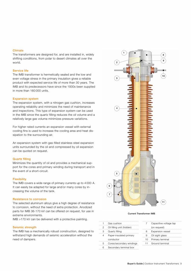
ClimateThe transformers are designed for, and are installed in, widely shifting conditions, from polar to desert climates all over the world.
Service lifeThe IMB transformer is hermetically sealed and the low and even voltage stress in the primary insulation gives a reliable product with expected service life of more than 30 years. The IMB and its predecessors have since the 1930s been supplied in more than 160 000 units.
Expansion systemThe expansion system, with a nitrogen gas cushion, increases operating reliability and minimizes the need of maintenance and inspections. This type of expansion system can be used in the IMB since the quartz filling reduces the oil volume and a relatively large gas volume minimizes pressure variations.
For higher rated currents an expansion vessel with external cooling fins is used to increase the cooling area and heat dis-sipation to the surrounding air.
An expansion system with gas-filled stainless steel expansion units surrounded by the oil and compressed by oil expansion can be quoted on request.
Quartz fillingMinimizes the quantity of oil and provides a mechanical sup-port for the cores and primary winding during transport and in the event of a short-circuit.
FlexibilityThe IMB covers a wide range of primary currents up to 4 000 A. It can easily be adapted for large and/or many cores by in-creasing the volume of the tank.
Resistance to corrosionThe selected aluminum alloys give a high degree of resistance to corrosion, without the need of extra protection. Anodized parts for IMB 36-170 kV can be offered on request, for use in extreme environments. IMB >170 kV can be delivered with a protective painting.
Seismic strengthThe IMB has a mechanically robust construction, designed to withstand high demands of seismic acceleration without the need of dampers.
Current Transformer IMB
1
3
4
8
9
10
11
5
7
6
2
1 Gas cushion
2 Oil filling unit (hidden)
3 Quartz filling
4 Paper-insulated primary
conductor
5 Cores/secondary windings
6 Secondary terminal box
7 Capacitive voltage tap
(on request)
8 Expansion vessel
9 Oil sight glass
10 Primary terminal
11 Ground terminal

10 Outdoor Instrument Transformers | Buyer’s Guide
ABB’s inductive voltage transformers are intended for connection between phase and ground in networks with insulated or direct-grounded neutral points.
The design corresponds with the requirements in the IEC and IEEE standards. Special design solutions to meet other stan-dards and customer requirements are also possible. The transformers are designed with a low flux density in the core and can often be dimensioned for 190% of the rated voltage for more than 8 hours.
Primary windingsThe primary winding is designed as a multi-layer coil of double enamelled wire with layer insulation of special paper. Both ends of the windings are connected to metal shields.
Secondary and tertiary windingsIn its standard design the transformer has a secondary measurement winding and a tertiary winding for ground fault protection, but other configurations are available as required. (2 secondary windings in a design according to IEEE standard) The windings are designed with double enamelled wire and are insulated from the core and the primary winding with pressboard (presspahn) and paper. The windings can be equipped with additional terminals for other ratios (taps).
CoreThe transformer has a core of carefully selected material, to give a flat magnetization curve. The core is over-dimensioned with a very low flux at operating voltage.
ImpregnationHeating in a vacuum dries the windings. After assembly, all free space in the transformer (approximately 60%) is filled with clean and dry quartz grains. The assembled transformer is vacuum-treated and impregnated with degassed mineral oil. The transformer is always delivered oil-filled and hermetically sealed.
Tank and insulator EMF 52-170: The lower section of the transformer consists of an aluminum tank in which the winding and core are placed. The tank consists of selected aluminum alloys that give a high degree of resistance to corrosion, without the need of extra protection. Anodized aluminum can be offered on request. The sealing system consists of O-ring gaskets.
The insulator, in its standard design, consists of high quality, brown glazed porcelain. The voltage transformers can also be supplied with silicone rubber insulators.
Expansion systemThe EMF has an expansion vessel placed on the top section of the porcelain. The EMF has a closed expansion system, without moving parts and with a nitrogen cushion, that is compressed by the expansion of the oil. A prerequisite for this is that the quartz sand filling reduces the oil volume, and the use of a relatively large gas volume, which gives small pres-sure variations in the system.
Ferro-resonanceThe design of the EMF notably counteracts the occurrence of ferro-resonance phenomena:
− The low flux in the core at the operating voltage gives a large safety margin against saturation if ferro-resonance oscillations should occur.
− The flat magnetization curve gives a smooth increase of core losses, which results in an effective attenuation of the ferro-resonance.
If the EMF transformer will be installed in a network with a high risk for ferro-resonance, it can, as a further safety precaution, be equipped with an extra damping burden, on a delta connected tertiary winding. See the figure below.
EMF Design features and advantages
Damping of ferro-resonance
a n a n a n
A N A N A N
da dn da dn da dn
60 ohm, 200 W
RS
T

Buyer’s Guide | Outdoor Instrument Transformers 11
ClimateThese transformers are designed for, and are installed in a wide range of shifting conditions, from polar to desert cli-mates all over the world.
Service LifeThe low and even voltage stresses in the primary winding give a reliable product with a long service life. EMF and its prede-cessors have been supplied in more than 55 000 units since the 1940s.
Expansion system The expansion system based on the nitrogen cushion gives superior operating reliability and minimizes the need of main-tenance and inspection of the transformer.
Quartz fillingMinimizes the quantity of oil and provides a mechanical sup-port to the cores and primary winding.
Resistance to corrosionEMF 52-170: The selected aluminum alloys give a high degree of resistance to corrosion without the need of extra protection. Anodized aluminum can be offered on request.
Seismic strengthEMF is designed to withstand the high demands of seismic acceleration.
Voltage transformer EMF 145
1
2
4
5
7
8
9
12
13
14
15
11
10
3
61 Primary terminal
2 Oil level sight glass
3 Oil
4 Quartz filling
5 Insulator
6 Lifting lug
7 Secondary terminal box
8 Neutral end terminal
9 Expansion system
10 Paper insulation
11 Tank
12 Primary winding
13 Secondary windings
14 Core
15 Ground connection

12 Outdoor Instrument Transformers | Buyer’s Guide
CPB Design features and advantages
ABB’s Capacitor Voltage Transformers (CVTs) are intended for connection between phase and ground in networks with isolated or grounded neutral.
ABB offers a world-class CVT with superior ferro-resonance suppression and transient response.
The design corresponds to the requirements of IEC and ANSI and all national standards based upon them. Special designs to meet other standards and customer unique specifications are also available.
The high quality, state of the art, automated manufacture of the capacitor elements provides consistent quality to ensure long term reliability and performance. Due to the optimized proportions of the mixed dielectric, the capacitor elements are subject to low electrical stress with high stability under extreme temperature variations.
CPB portfolio featuresThe portfolio consists of three versions of Capacitor Voltage Dividers (CVDs), light, medium and heavy, combined with two sizes of Electromagnetic Units (EMU). The two sizes of EMU comprise a medium size optimized in respect to market re-quirements for number of windings and performance. A lighter EMU is available where customers have lower burden require-ments. The light capacitance CVD is manufactured up to 245 kV and can only be incorporated with the lightweight EMU. This special cost effective combination is in this document designated CPB(L).
Capacitor Voltage DividerThe capacitor voltage divider (CVD) consists of one or more capacitor units, assembled on top of each other, with each unit containing the required number of series-connected, oil-insulated capacitor elements. The units are completely filled with synthetic oil, hermetically sealed with stainless steel bel-lows and incorporate o-ring seals throughout the design.
The design of the capacitive elements is consistent with requirements of revenue metering, with the active component of aluminum foils insulated with polypropylene film and paper and impregnated with PCB free synthetic oil. The synthetic oil has superior and consistent insulating properties when com-pared to mineral oil.
The automated processing of the capacitor units further contributes to the long term high reliability and performance of the CPB.
Electromagnetic Unit (EMU)The voltage divider and the electromagnetic unit are connect-ed by internal bushings, which is necessary for applications with high accuracy.
The EMU has double-enamelled copper windings and an iron core assembled with high quality magnetic core steel and is oil impregnated and mounted in a hermetically sealed alumi-num tank with mineral oil filling.
The primary winding is divided into a main part, and a set of externally adjustable connected trimming windings. The nomi-nal intermediate voltage is approximately 22/√3 kV.
The EMU incorporates an inductive reactor, connected in series between the voltage divider and the high voltage end of the primary winding to compensate for the shift in phase angle caused by the capacitive reactance of the CVD. This inductive reactance is tuned individually on each transformer to achieve the required accuracy.
For special applications, such as HVDC stations, measure-ment of harmonics, etc an alternative EMU is available without a separate compensating reactor. For this special type of EMU the function of the compensating reactor and primary wind-ing of the intermediate transformer are combined into one device. This arrangement gives additional advantages such as a wider frequency operating range and further improvement in the transient response. This special type of EMU is limited to lower burden requirements.

Buyer’s Guide | Outdoor Instrument Transformers 13
Climate These transformers are designed for, and are installed in widely varying conditions, from arctic to desert climates, on every continent.
Ferro-resonance The low induction, combined with an efficient damping circuit, gives a safe and stable damping of ferro-resonance at all frequencies and voltages up to the rated voltage factor; see page 40.
Life timeThe low voltage stress within the capacitor elements ensures a safe product with an expected service life of more than 30 years. The long term reliability and performance is further ensured by the state of the art, automated manufacture and processing of the capacitor elements and units.
Transient propertiesThe high intermediate voltage and high capacitance result in good transient properties.
Adjustment The adjustment windings for ratio adjustment are accessible in the terminal box, under a sealed cover.
Power Line Carrier (PLC)The CPB is designed with the compensating reactor connect-ed on the high voltage side of the primary winding, providing the option of using higher frequencies (> 400 kHz) for power line carrier transmission.
Stray capacitance The design with the compensating reactor on the high voltage side of the main winding ensures less than 200 pF stray ca-pacitance, which is the most stringent requirement in the IEC standard for carrier properties.
Stability The CPB has a high Quality Factor as a result of the compara-tively high capacitance combined with the high intermediate voltage. The Quality Factor = Cequivalent x U2
intermediate is a mea-sure of the accuracy stability and the transient response. The higher this factor, the better the accuracy, and the better the transient response.
Capacitor Voltage Divider
1 Expansion system
2 Capacitor elements
3 Intermediate voltage bushing
8 Primary terminal, flat 4-hole Al-pad
10 Low voltage terminal (for carrier frequency use)
Electromagnetic unit
4 Oil level glass
5 Compensating reactor
6 Ferro-resonance damping circuit
7 Primary and secondary windings
9 Gas cushion
11 Terminal box
12 Core
11
2
10
712
3
5
9
4
6
1
8

14 Outdoor Instrument Transformers | Buyer’s Guide
CCA and CCB Design features and advantages
ABB’s coupling capacitors are intended for connection between phase and ground in networks with isolated or grounded neutral.
ApplicationABB offers a world-class coupling capacitor with superior properties for PLC application as well as filtering and other general capacitor applications. ABB’s coupling capacitors (designated CCA and CCB) are intended for connection between phase and ground in high voltage networks with isolated or grounded neutral. The design corresponds to the requirements of IEC 60358 and all national standards based on this standard. Special designs to meet other standards and customer specifications are also available. Due to the design of the capacitor units, described below, the coupling capacitor elements are combining both low voltage stress and high stability to temperature variations.
Difference of CCA and CCBThe design of the CCA and CCB is basically identical however the CCB has a larger diameter with space for larger capacitor element windings making it capable of extra high capacitance. Thus the coupling capacitor with standard capacitance is called CCA and the coupling capacitor with extra high capaci-tance is called CCB.
Capacitor designThe coupling capacitor consists of one or two capacitor units, assembled on top of each other. Each unit contains a large number of series-connected, oil-insulated capacitor elements. The units are completely filled with synthetic oil, which is kept under a slight overpressure by the design of the expansion system. O-ring seals are used throughout the design.
The capacitor insulators and elements are designed with respect to the same demands as for the capacitor part of revenue metering CVT and thus also share the same conser-vative design philosophy. This conservative philosophy results in a design with low voltage stress that makes the coupling capacitors capable of handling a voltage factor up to 1.9/8hrs although this is not required by the IEC coupling capacitor standard. Their active component consists of aluminium foil, insulated with paper/polypropylene film, impregnated by a PCB-free synthetic oil which has better insulating properties than normal mineral oil and is required for the mixed dielectric. Due to its unique proportions between paper and polypropyl-ene film this dielectric has proven itself virtually insensitive to temperature changes.

Buyer’s Guide | Outdoor Instrument Transformers 15
Climate These coupling capacitors are designed for being installed in widely varying conditions, from arctic to desert climates, on every continent.
Life timeThe low voltage stress within the capacitor elements ensures a safe product with an expected service life of more than 30 years.
Power Line Carrier (PLC)The CCA and CCB are designed for use within the entire power line carrier transmission frequency range from 30 kHz to 500 kHz.
1
2
3
44
56
Capacitor Voltage Divider CCA or CCB
1 Primary terminal, flat 4-hole Al-pad
2 Expansion system
3 Capacitor elements
4 Rating plate
5 L- (low voltage) terminal / Ground clamp
6 Support Insulators (mainly for PLC use)

16 Outdoor Instrument Transformers | Buyer’s Guide

Buyer’s Guide | Outdoor Instrument Transformers 17
For revenue metering and protection in high voltage networks, the oil-paper insulated current transformer IMB is the most sold transformer in the world.
− Designed for widely shifting conditions, from polar to desert climate
− Flexible tank type design allows large and/or many cores
The unique quartz filling minimizes the quantity of oil and provides a mechanical support to the cores and primary winding. Due to the low center of gravity the IMB is very suitable for areas with high seismic activity.From international studies we can see that the IMB design is a reliable product (failure rate more than 4 times lower than average) with no need for regular maintenance.
IMB 36-800 kVTank type current transformer
Brief performance data
Installation Outdoor
Design Tank (Hairpin) type
Insulation Oil-paper-quartz
Highest voltage for equipment 36-765 kV
Max primary current Up to 4 000 A
Short-circuit current Up to 63 kA/1 sec
Insulators Porcelain
On request silicon rubber (SIR)
Creepage distance ≥ 25 mm/kV
(Longer on request)
Service conditions
Ambient temperature
Design altitude
-40 °C to +40 °C
(Others on request)
Maximum 1000 m
(Others on request)

18 Outdoor Instrument Transformers | Buyer’s Guide
MaterialAll external metal surfaces are made of an aluminum alloy, resistant to most known environment factors. Bolts, nuts, etc. are made of acid-proof steel. The aluminum surfaces do not normally need painting. We can, however, offer anodized aluminum or a protective paint.
Creepage distanceAs standard, IMB is offered with creepage distance ≥ 25 mm/kV. Longer creepage distance can be provided on request.
Mechanical stabilityThe mechanical stability gives sufficient safety margins for normal wind loads and terminal forces. Static force on primary terminal may be up to 6 000 N in any direction. The IMB will also withstand most cases of seismic stress.
Rating platesRating plates of stainless steel with engraved text and the wir-ing diagram are mounted on the cover of the terminal box.
Transport - storageThe IMB 36 - 145 is normally transported (3-pack) and stored vertically. If horizontal transport is required this must be stated on the order. The IMB 170 - 800 is packed for horizontal transport (1-pack).
Long-term storage of more than six months should preferably be made vertically. If this is not practical please contact ABB.
Arrival inspection - assemblyPlease check the packaging and contents with regard to transport damage on arrival. In the event of damage to the goods, contact ABB for advice before further handling of the goods. Any damage should be documented (photographed).
The transformer must be assembled on a flat surface. An un-even surface can cause misalignment of the transformer, with the risk of oil leakage.
Assembly instructions are provided with each delivery.
MaintenanceThe maintenance requirements are small, as IMB is hermeti-cally sealed and designed for a service life of more than 30 years. Normally it is sufficient to check the oil level and that no oil leakage has occurred. Tightening of the primary connec-tions should be checked occasionally to avoid overheating.
A more detailed check is recommended after 20-25 years of service. A manual for conditional monitoring can be sup-plied on request. This gives further guarantees for continued problem-free operation.
The methods and the scope of the checks depend greatly on the local conditions. Measurements of the dielectric losses of the insulation (tan delta-measurement) and/or oil sampling for dissolved gas analysis are recommended check methods.
Maintenance instructions are supplied with each delivery.
Oil samplingThis is normally done through the oil-filling terminal. If re-quired, we (ABB, HV Components) can offer other solutions and equipment for oil sampling.
Impregnation agentOil of type Nynäs Nytro 10 XN (according to IEC 60296 grade 2) is free of PCB and other heavily toxic substances and has a low impact on the environment.
DisposalAfter separating the oil and quartz the oil can be burned in an appropriate installation. Oil residue in the quartz can be burnt, whereafter the quartz can be deposited.
The disposal should be carried out in accordance with local regulatory requirements. The porcelain can, after it has been crushed, be used as landfill. The metals used in the transformer can be recycled. To recy-cle the aluminum and copper in the windings, the oil-soaked paper insulation should be burnt.
IMB 36-800 kVTank type current transformer

Buyer’s Guide | Outdoor Instrument Transformers 19
Primary terminalsIMB 36 – 800 is as standard equipped with aluminum bar terminals, suitable for IEC and NEMA specifications. Other customer specific solutions can be quoted on request.
Maximum static and dynamic force on the terminal is up to 6 000 and 8 400 N respectively, depending on type of IMB. Maximum torsional moment is 1 000 Nm.
Secondary terminal box and secondary terminals The transformer is equipped with a secondary terminal box, protection class IP 55, according to IEC 60529. This box is equipped with a detachable, undrilled gland plate, which on installation can be drilled for cable bushings.
The terminal box is provided with a drain. The standard terminal box can accommodate up to 30 termi-nals of the type Phoenix UK10N for cross section <10 mm2. Other types of terminals can be quoted on request.
A larger terminal box with space for more secondary terminals or other equipment, such as heater or protective spark gaps, is supplied when needed.
Ground (earth) terminalThe transformer is normally equipped with a ground clamp with a cap of nickel-plated brass, for conductors 8-16 mm (area: 50-200 mm2), which can be moved to either mounting foot.
A stainless steel bar, 80 x 145 x 8 mm, can be quoted on request. The bar can be supplied drilled according to IEC or NEMA standards.
The ground terminal for the secondary windings is located inside the terminal box.
14 40
50
13540
20
75100
IMB 36-245
Standard for IMB 36-245
Standard for IMB 245-800
IMB 245-420
IMB 420-550 IMB 420-800

20 Outdoor Instrument Transformers | Buyer’s Guide
IMB 36-800 kVTank type current transformer
Maximum continuous primary current and short-time currentType Normal current Cooling flanges Cooler Maximum short-time
current 1 sec
Maximum short-time
current 3 sec
Maximum dynamic
current
A A A kA kA kA peak value
IMB 36-170 2400 - 3150 63 40 170
1200 - 1500 40 40 108
400 - - 31.5 18 85
150 - - 16 9 43
IMB 245 1600 - 2000 40 40 108
IMB 245 2000 2400 3150 63 63 170
1000 1200 1500 40 40 108
300 - - 31.5 18 85
150 - - 16 9 45
IMB 300-420 2500 - 3150 63 63 170
1200 - 1500 40 40 108
IMB 420-550 2500 - 4000 63 40 170
1200 - 2000 40 40 108
IMB 800 - - 4000 63 40 170
Other types of primary conductors can be supplied on requestMaximum continuous primary current = load factor x primary rated current related to a daily mean temperature that does not exceed 35 oCPrimary winding can be designed with reconnection alternative between two or three primary rated currents with a ratio of 2:1 or 4:2:1
Test Voltages IEC 60044-1Type Highest voltage for
equipment (Um)
AC voltage test,
1 minute, wet/dry
Lightning impulse
1.2/50 μs
Switching impulse
250/2500 μs
RIV test
voltage
Max RIV
level
kV kV kV kV kV Max. μV
IMB 72 72,5 140/140 325 - - -
IMB 123 123 230/230 550 - 78 2500
IMB 145 145 275/275 650 - 92 2500
IMB 170 170 325/325 750 - 108 2500
IMB 245 245 460/460 1050 - 156 2500
IMB 300 300 -/460 1050 850 191 2500
IMB 362 362 -/510 1175 950 230 2500
IMB 420 420 -/630 1425 1050 267 2500
IMB 550 550 -/680 1550 1175 334 2500
IMB 800 765 -/975 2100 1550 486 2500Test voltages above applies at ≤1000 meters above sea level
Test Voltages IEEE C 57.13Type Highest system
voltage
Power frequency
applied voltage test
AC-test Wet,
10 sec
Lightning impulse
(BIL) 1.2/50 μs
Chopped
impulse
RIV test
voltage
Max RIV
level1)
kV kV kV kV Max. kV kV μV
IMB 36 36.5 70 70 200 230 21 125
IMB 72 72.5 140 140 350 400 42 125
IMB 123 123 230 230 550 630 78 250
IMB 145 145 275 275 650 750 92 250
IMB 170 170 325 315 750 865 108 250
IMB 245 245 460 445 1050 1210 156 250
IMB 362 362 575 - 1300 1500 230 250
IMB 550 550 800 - 1800 2070 334 5001) Test procedure according to IEC. Test voltages above applies at ≤1000 meters above sea level

Buyer’s Guide | Outdoor Instrument Transformers 21
Nominal flashover and creepage distance (Porcelain)Normal creepage distance 25 mm/kV
(Min. values)
Long creepage distance 31 mm/kV
(Min. values)
Type Flashover
distance
Total creepage
distance
Protected creepage
distance
Flashover
distance
Total creepage
distance
Protected creepage
distance
mm mm mm mm mm mm
IMB 36 - - - 630 2248 1020
IMB 72 - - - 630 2248 1020
IMB 123 1120 3625 1400 1120 4495 1860
IMB 145 1120 3625 1400 1120 4495 1860
IMB 170 - - - 1330 5270 2200
IMB 1701) - - - 1600 6525 2740
IMB 245 1915 6740 2850 2265 8490 3685
IMB 300 2265 8250 3495 2715 10430 4645
IMB 362 2715 10430 4645 3115 12480 5630
IMB 420 3115 12480 5630 3635 14325 6465
IMB 420 3220 11550 4800 3820 15280 6870
IMB 550 3820 15280 6870 4715 18944 8340
IMB 800 5220 18624 7950 - - -
Note: Long creepage distance effects dimensions A, B, D (see dimensions)1) 38 mm/kV for 170 kV system voltage and 45 mm/kV for 145 kV system voltage is available.
Standard accuracy Classes.Current transformers of the type IMB are designed to comply with the following accuracy classes. Other classes can be quoted on request.
IEC 60044 – 1 IEEE C57.13 / IEEE C57.13.6
Class Application Class Application
0.2 Precision revenue metering 0.15 Precision revenue metering
0.2S Precision revenue metering 0.3 Standard revenue metering
0.5 Standard revenue metering 0.6 Metering
0.5S Precision revenue metering 1.2 Metering
1.0 Industrial grade meters C100 Protection
3.0 Instruments C200 Protection
5.0 Instruments C400 Protection
5P Protection C800 Protection
5PR Protection
10P Protection
10PR Protection
PX Protection
TPS Protection
TPX Protection
TPY Protection

22 Outdoor Instrument Transformers | Buyer’s Guide
IMB 36-800 kVTank type current transformer
BurdensOur current transformer IMB has a very flexible design allow-ing large burdens. However, it is important to determine the real power consumption of connected meters and relays in-cluding the cables. Unnecessary high burdens are often speci-fied for modern equipment. Note that the accuracy for the measuring core, according to IEC, can be outside the class limit if the actual burden is below 25% of the rated burden.
Over-voltage protection across primary windingThe voltage drop across the primary winding of a current transformer is normally very low. At rated primary current it is only a couple of volts and at short-circuit current a few hundred volts.
If a high frequency current or voltage wave passes through the primary winding can, due to the winding inductance, high voltage drops occur. This is not dangerous for a current transformer with a single-turn primary winding, but for multi-turn primaries may it lead to dielectric puncture between the primary turns.
It is therefore ABB’s practice to protect the primary winding in multi-turn designs with a surge arrester connected in parallel with the primary.
Standard design of IMB current transformer is without surge arrester. Surge arrester of type POLIM – C 1.8 will however be included when needed.

Buyer’s Guide | Outdoor Instrument Transformers 23
IMB 36-800 kVDesign and shipping data
DimensionsA B C D E F G H J K
Type Total
height
Height to
primary
terminal
Ground
level
height
Flashover
distance
Length across
primary terminal
bushing
Dimension of
bottom tank
Height to
terminal box
Spacing for
mounting holes
mm mm mm mm mm mm mm mm mm mm
IMB 361) 2000 1635 840 630 475 270 410 460 60 410
IMB 721) 2000 1635 840 630 475 270 410 460 60 410
IMB 1231) 2490 2125 840 1120 475 270 410 460 60 410
IMB 1451) 2490 2125 840 1120 475 270 410 460 60 410
IMB 1701) 2700 2335 840 1330 475 270 410 460 60 410
IMB 2451) 3320 2950 860 1915 439 270 410 460 60 410
IMB 2452) 3640 3050 965 1915 439 270 395 885 485 450
IMB 3002) 4150 3405 965 2265 491 270 395 885 485 450
IMB 3622) 4600 3855 965 2715 491 270 395 885 485 450
IMB 4202) 5000 4255 965 3115 491 270 395 885 485 450
IMB 4203) 5505 4760 1365 3220 491 320 380 1040 783 500
IMB 4204) 5580 4790 1390 3220 526 360 410 1105 805 600
IMB 5503) 6105 5360 1365 3820 491 320 380 1040 783 500
IMB 5504) 6180 5390 1390 3820 526 360 410 1105 805 600
IMB 8004) 8540 6790 1390 5220 526 360 410 1105 805 600
1) Standard tank, 2) Hexagonal tank, 3) Octagon tank, 4) HV tank
IMB 36 - 170
J
CD
E
A
B
K
25
HK
K
G F

24 Outdoor Instrument Transformers | Buyer’s Guide
IMB 36-800 kVDesign and shipping data
E
DC
K
J
K
25
A
B
HK
K
G F
G
E
J
CD
K
A
B
H
K
FG
25
IMB 245 2)
IMB 245 1)
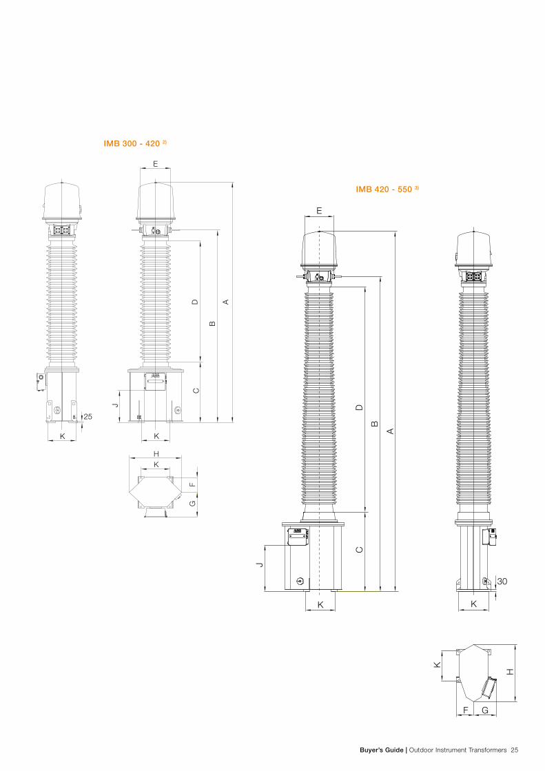
Buyer’s Guide | Outdoor Instrument Transformers 25
K
J
K
CD
B
A
E
HK
FG
25
K
J
E
CD
B
A
K
F G
H
K
30
IMB 300 - 420 2)
IMB 420 - 550 3)

26 Outdoor Instrument Transformers | Buyer’s Guide
30
E
D
B
A
C
J
K K
K H
F G
IMB 36-800 kVDesign and shipping data
IMB 420 - 550 4)

Buyer’s Guide | Outdoor Instrument Transformers 27
30
K
K
F G
H
E
C
B
D
A
K
J
IMB 800 4)

28 Outdoor Instrument Transformers | Buyer’s Guide
IMB 36-800 kVDesign and shipping data
Changes, special design of dimensionsA, B, C A A A
Tank-type Increased tank height Cooling flange Cooler Three primary ratios
mm mm mm mm
Standard tank 210 - 255 0
Hexagon tank 210 or 420 210 35 / 240 *) -
Octagon tank 150 - 440 -
HV tank 200 or 400 - 400 **) -
*) 35 mm for IMB 245, 240 mm for IMB 300 - 420**) 400 mm for IMB 420 - 550, IMB 800 is always equipped with cooler
Shipping data for standard IMBType Net weight Incl. oil Oil Shipping weight Shipping dimensions Shipping volume
1-pack/3-pack 1-pack/3-pack 1-pack/3-pack
kg kg kg LxWxH m m3
IMB 36 1) 420 45 550 / 1630 2.26x0.6x0.94 / 1.67x0.8x2.21 1.3 / 3
IMB 72 1) 420 45 550 / 1630 2.26x0.6x0.94 / 1.67x0.8x2.21 1.3 / 3
IMB 123 1) 490 50 650 / 1850 2.75x0.6x0.94 / 1.67x0.8x2.7 1.5 / 3.6
IMB 145 1) 490 50 650 / 1850 2.75x0.6x0.94 / 1.67x0.8x2.7 1.5 / 3.6
IMB 170 1) 550 55 700 / - 2.96x0.6x0.94 / - 1.7 / -
IMB 245 1) 750 80 970 / - 3.48x0.6x0.94 / - 2.0 / -
IMB 245 2) 1100 110 1390 / - 3.82x1.06x1.02 / - 4.2 / -
IMB 300 2) 1400 170 1815 / - 4.76x1.08x1.10 / - 5.7 / -
IMB 362 2) 1500 180 1915 / - 4.76x1.08x1.10 / - 5.7 / -
IMB 420 2) 1600 190 2050 / - 5.21x1.08x1.10 / - 6.2 / -
IMB 420 3) 2500 300 3120 / - 5.82x1.23x1.22 / - 8.8 / -
IMB 420 4) 2600 290 3220 / - 5.74x1.06x1.47 / - 9.0 / -
IMB 550 3) 2800 330 3480 / - 6.42x1.23x1.22 / - 9.7 / -
IMB 550 4) 3500 510 4180 / - 6.34x1.06x1.47 / - 9.9 / -
IMB 800 4) 4200 670 6400 / - 8.71x1.06x1.47 / - 13.5 / -1) Standard tank 2) Hexagonal tank 3) Octagon tank 4) HV tank
IMB 36 - 145 is normally packed for vertical transport in a 3-pack. Vertical transport in a 1-pack can be quoted on request. IMB 170 - 800 is always packed for horizontal transport in 1-pack.
Additional weightsWeight indicated in table above is for standard IMB. Additional weights may occur depending on requirements and configuration.

Buyer’s Guide | Outdoor Instrument Transformers 29
IMB 36-800 kVReconnection
GeneralThe current transformer can be reconnected to adapt for vary-ing currents. The IMB type can be delivered in a configuration that permits reconnecttion either on primary or secondary side, or a combination of the two.
Connection above is for the lower current Connection above is for the higher current
The unused taps on the reconnectable secondary winding must be left open. If windings/cores are not used in a current transformer they must be short-circuited between the highest ratio taps (e.g. S1 - S5) and shall be grounded.
Secondary Reconnection
Two primary ratios for two turns Two primary ratios, connected for one turn
C2C1C2
C1
P1 P2
S1 S5S4S3S2
Caution! Never leave an unused secondary winding open. Very high-induced voltages are generated across the terminals and both the user and the transformer are subjected to danger.
Primary reconnection
The advantage of primary reconnection is that the ampere-turns remains the same and thereby the output (VA). The dis-advantage is that the short-circuit capability may be reduced for the lower ratio(s).

30 Outdoor Instrument Transformers | Buyer’s Guide

Buyer’s Guide | Outdoor Instrument Transformers 31
EMF 52-170 kVInductive voltage transformer
For revenue metering and protection in high voltage networks, the oil-paper insulated voltage transformer EMF is the most sold inductive voltage transformer in the world.
− Designed for widely shifting conditions, from polar to desert climate.
− Low flux in the core at operating voltage gives a wide safety margin against saturation and ferro-resonance.
The unique quartz filling minimizes the quantity of oil and allows a simple and reliable expansion system.
Brief performance data
Installation Outdoor
Design Inductive type
Insulation Oil-paper-quartz
Highest voltage for equipment 52-170 kV
Voltage factor (Vf) Up to 1.9/8 hrs
Insulators Porcelain
On request silicon rubber (SIR)
Creepage distance ≥ 25 mm/kV
(Longer on request)
Service conditions
Ambient temperature
Design altitude
-40 °C to +40 °C
(Others on request)
Maximum 1000 m
(Others on request)

32 Outdoor Instrument Transformers | Buyer’s Guide
EMF 52-170 kVInductive voltage transformer
MaterialEMF 52-170: All external metal surfaces are made of an aluminum alloy, resistant to most known environment factors. Bolts, nuts, etc. are made of acid-proof steel. The aluminum surfaces do not normally need painting. We can, however, of-fer a protective paint or anodized aluminum.
Creepage distanceEMF is available as standard with normal or long creepage distances according to the table on page 34. Longer creep-age distances can be quoted on request.
Mechanical stabilityThe mechanical stability gives a sufficient safety margin for normal wind loads and stress from conductors. EMF can also withstand high seismic forces.
Rating platesRating plates of stainless steel, with engraved text and wiring diagrams are mounted on the transformer enclosure.
Arrival inspection - assemblyPlease check the packaging and contents with regard to transport damage on arrival. In the event of damage to the goods, contact ABB for advice, before further handling of the goods. Any damage should be documented (photographed).
The transformer must be assembled on a flat surface. An un-even surface can cause misalignment of the transformer, with the risk of oil leakage.
Assembly instructions are provided with each delivery.
MaintenanceMaintenance requirements are insignificant as EMF is de-signed for a service life of more than 30 years.
Normally it is only necessary to check that the oil level is cor-rect, and that no oil leakage has occurred. The transformers are hermetically sealed and therefore require no other inspection.
A comprehensive inspection is recommended after 30 years. This provides increased safety and continued problem-free operation. The inspection methods and scope very significant-ly depending on the local conditions. As the primary winding is not capacitive graded, the measurement of tan-delta gives no significant result. Therefore oil sampling for dissolved gas analysis is recommended for checking the insulation.
Maintenance instructions are supplied with each delivery.
ABB, High Voltage Products is at your disposal for discus-sions and advice.
Impregnation agentOil of type Nynäs Nytro 10 XN (according to IEC 296 grade 2) is free of PCB and other heavily toxic substances and has a low impact on the environment.
DisposalAfter separating the oil and quartz the oil can be burned in an appropriate installation. Oil residue in the quartz can be burnt, whereafter the quartz can be deposited.
The disposal should be carried out in accordance with local regulatory requirements.
The porcelain can, after it has been crushed, be used as landfill.
The metals used in the transformer can be recycled. To recy-cle the copper in the windings, the oil-soaked paper insulation should be burnt.

Buyer’s Guide | Outdoor Instrument Transformers 33
Primary terminalsEMF 52-170 is as standard equipped with an aluminum bar terminal, suitable for IEC and NEMA specifications.
The primary terminal is a voltage terminal and should therefore, according to standards, withstand static force of 1 000 N for Um (system voltage) 123 – 170 kV and 500 N for lower voltages. Withstand dynamic force is 1 400 and 700 N respectively.
Secondary terminal box and Secondary terminalsThe terminal box for the secondary winding terminal is mounted on the transformer enclosure. As standard the terminal box is manufactured of corrosion resistant, cast aluminum.
This box is equipped with a detachable, undrilled gland plate, which on installation can be drilled for cable bushings. It can, on request, be quoted with cable glands according to the custom-er’s specification.
The terminal box is provided with a drain.
EMF 52-170: Secondary terminals accept wires with cross-sections up to 10 mm2.
Protection class for the terminal box is IP 55.
Ground (Earth) connectionsThe transformer is normally equipped with a ground terminal with a clamp of nickel-plated brass. For conductors Ø=5-16 mm (area 20-200 mm2), see the figure.
A stainless steel bar, 80 x 145 x 8 mm, can be quoted on request. The bar can be supplied drilled according to IEC or NEMA standards.
Grounding of the secondary circuits is made inside the terminal box.
EMF 52-170
EMF 52-84 EMF 123-170
EMF 52-84
EMF 123-170

34 Outdoor Instrument Transformers | Buyer’s Guide
EMF 52-170 kVDesign data
Nominal flash-over and creepage distanceNormal porcelain (min. nom. values) Porcelain with long creepage distance (min. nom. values)
Type Flash-over
distance
Creepage
distance
Protected creepage
distance
Flash-over
distance
Creepage
distance
Protected creepage
distance
mm mm mm mm mm mm
EMF 52 630 2248 1020
Others on request.
Normally insulator for the nearest higher voltage.
EMF 72 630 2248 1020
EMF 84 630 2248 1020
EMF 123 1200 3625 1400
EMF 145 1200 3625 1400
EMF 170 1330 5270 2200
Test voltages IEC 60044-2, (SS-EN 60044-2) Type Highest voltage for
equipment
(Um)
1min
wet/dry
LIWL
1.2/50 μs
RIV test
voltage
RIV level
kV kV kV kV Max. μV
EMF 52 52 95 250 30 125
EMF 72 72.5 140 325 46 125
EMF 84 84 150 380 54 125
EMF 123 123 230 550 78 2500
EMF 145 145 275 650 92 2500
EMF 170 170 325 750 108 2500
Test voltages above are valid for altitudes ≤1000 meters above sea level.
Test voltages IEEE C 57.13 (CAN 3 – C 131 – M83)Type Highest voltage for equipment
(Um)
AC test
dry, 1 min
AC test
wet, 10 sec
BIL
1.2/50 μs
kV kV kV kV Max.
EMF 52 52 95 95 250
EMF 72 72.5 140 175 350
EMF 123 121 (123) 230 230 550
EMF 145 145 275 275 650
EMF 170 169 (170) 325 315 (325) 750
Values within brackets refer to CAN 3-C13.1-M79. Test voltages above are valid for altitudes ≤ 1000 meters above sea level.

Buyer’s Guide | Outdoor Instrument Transformers 35
Secondary voltages and burdens according to IEC
StandardsInternational IEC 60044-2 Swedish Standard SS-EN 60044-2 All national standards based on IEC
Rated data at 50 or 60 Hz, Voltage factor 1.5 or 1.9The transformer normally has one or two windings for continu-ous load and one residual voltage winding. Other configurations can be quoted according to require-ments.
Standard accuracy classes and burdensAccording to IEC
50 VA class 0.2 100 VA class 3P
100 VA class 0.5 100 VA class 3P
150 VA class 1.0 100 VA class 3P
For lower or higher burdens please contact us.
The standards state as standard values for rated voltage factor 1.5/30 sec. for effectively earthed systems, 1.9/30 sec. for systems without effective earthing with automatic earth fault tripping and 1.9/8 hrs for systems with insulated neutral point without automatic earth fault tripping.
Since the residual voltage winding is not loaded except dur-ing a fault, the effect of its load on the accuracy of the other windings is disregarded in accordance with IEC.
Please note that modern meters and protection require much lower burdens than those above, and to achieve best accuracy you should avoid specifying burdens higher than necessary; see page 6.
Secondary voltages and burdens according to IEEE and CAN3
StandardsAmerican IEEE C57.13-1993 Canadian CAN3-C13-M83
Rated data at 60 Hz, Voltage factor 1.4The transformer normally has one or two secondary windings for continuous load (Y-connected).
Example of turns ratios: 350-600:1 means one secondary winding with the ratio 350:1 and one tertiary winding ratio 600:1 350/600:1:1 means one secondary winding and one tertiary winding both with taps for ratios 350:1 and 600:1
Protective classes according to CAN (1P, 2P, 3P) can be quoted on request.
Voltage factor 1.9 according to CAN can be quoted on request.
Standard accuracy classes and burdensAccording to IEEE and CAN3
0.3 WXY 0.6 WXYZ 1.2/3P WXYZ
For lower or higher burdens please contact us.
Rated burdens: W = 12.5 VA power factor 0.1 X = 25 VA power factor 0.7 Y = 75 VA power factor 0.85 YY = 150 VA power factor 0.85 Z = 200 VA power factor 0.85 ZZ = 400 VA power factor 0.85

36 Outdoor Instrument Transformers | Buyer’s Guide
EMF 52-170 kVDesign data
Voltage transformers EMF A B C D E F
Type Total
height
Flash-over
distance
Height to
terminal box
Fixing hole
dimensions
Ground level
height
Expansion
vessel diameter
mm mm mm mm mm mm
EMF 52 1464 630 114 335 x 335 540 324
EMF 72 1464 630 114 335 x 335 540 324
EMF 84 1464 630 114 335 x 335 540 324
EMF 123 2360 1200 65 410 x 410 760 416
EMF 145 2360 1200 65 410 x 410 760 416
EMF 170 2490 1330 65 410 x 410 760 416
EMF 52-84Note: Primary terminal will be mounted at site
EMF 123-170Note: Primary terminal will be mounted at site
A
BE
C
D
F
D20 mm
C
BE
D20 mm
A
D
F
135

Buyer’s Guide | Outdoor Instrument Transformers 37
EMF 52-170 kVShipping data
Voltage transformers EMFType Net weight incl. oil Oil Shipping weight Shipping dimensions Shipping volume
Porcelain insulator 3-pack 3-pack, L x W x H 3-pack
kg kg kg m m3
EMF 52 300 40 1040 1.6 x 0.9 x 1.7 2.5
EMF 72 300 40 1040 1.6 x 0.9 x 1.7 2.5
EMF 84 300 40 1040 1.6 x 0.9 x 1.7 2.5
EMF 123 570 80 1975 2.0 x 1.0 x 2.6 5.2
EMF 145 570 80 1975 2.0 x 1.0 x 2.6 5.2
EMF 170 610 83 2130 2.0 x 1.0 x 2.7 5.4
EMF 52 - 84 must not be tilted more than 60° during transport and storage.
Warning notes are placed on the transformer’s rating plate.
EMF 123 - 170 is normally packed for vertical transport (3-pack). However, it can be transported in a horizontal position and is available on request for horizontal transport (1-pack).

38 Outdoor Instrument Transformers | Buyer’s Guide
Buyer’s Guide | Outdoor Instrument Transformers 39
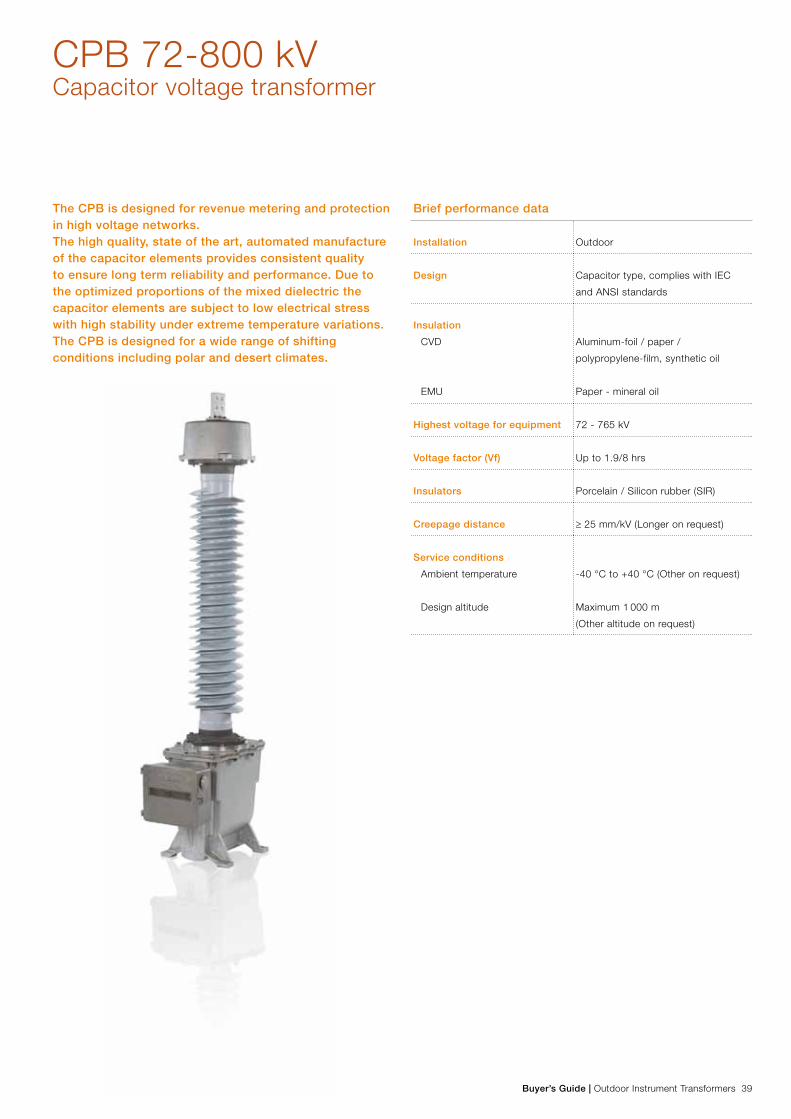
CPB 72-800 kVCapacitor voltage transformer
The CPB is designed for revenue metering and protection in high voltage networks. The high quality, state of the art, automated manufacture of the capacitor elements provides consistent quality to ensure long term reliability and performance. Due to the optimized proportions of the mixed dielectric the capacitor elements are subject to low electrical stress with high stability under extreme temperature variations. The CPB is designed for a wide range of shifting conditions including polar and desert climates.
Brief performance data
Installation Outdoor
Design Capacitor type, complies with IEC
and ANSI standards
Insulation
CVD
EMU
Aluminum-foil / paper /
polypropylene-film, synthetic oil
Paper - mineral oil
Highest voltage for equipment 72 - 765 kV
Voltage factor (Vf) Up to 1.9/8 hrs
Insulators Porcelain / Silicon rubber (SIR)
Creepage distance ≥ 25 mm/kV (Longer on request)
Service conditions
Ambient temperature
Design altitude
-40 °C to +40 °C (Other on request)
Maximum 1 000 m
(Other altitude on request)

40 Outdoor Instrument Transformers | Buyer’s Guide
MaterialAll external metal surfaces are made of an aluminum alloy, resistant to most known environment factors. Bolts, nuts, etc. are made of acid-proof stainless steel. The aluminum surfaces do not normally need painting. We can however offer anodiza-tion or protective paint, (normally light gray).
Creepage distanceAs standard the CPB is offered with creepage distance 25 mm/kV. Longer creepage distances can be offered on request.
Silicone Rubber InsulatorsThe complete CPB range is available with silicone rubber insulators. Our SIR insulators are produced with a patented helical extrusion molding technique, which gives completely joint-free insulators with outstanding performance. All CVTs with this type of insulators have the same high creepage dis-tance, 25 mm/kV phase-phase, as porcelain.
Mechanical stabilityThe mechanical stability gives sufficient safety margin for normal wind loads and conductor forces. For all combinations except CPB(L), it is possible to mount line traps on top of the capacitor divider. The CPB will also withstand most cases of seismic stress.
Ferroresonance damping circuitAll CVTs need to incorporate some kind of ferro-resonance damping, since the capacitance in the voltage divider, in series with the inductance of the transformer and the series reactor, constitutes a tuned resonance circuit.
This circuit can be brought into resonance, that may saturate the iron core of the transformer by various disturbances in the network. This phenomenon can also overheat the electro-magnetic unit, or lead to insulation breakdown.
The CPB use a damping circuit, connected in parallel with one of the secondary windings (see diagram on page 49). The damping circuit consists of a reactor with an iron core, and an oil-cooled resistor in series. Under normal use, the iron core of the damping reactor is not saturated, yielding a high impedance, so that practically no current is flowing through this circuit.
The damping circuit has two bridged terminals; d1- d2, be-hind a sealed covering hood in the terminal box. In particular cases, and after agreement, this bridge can be opened, to check that the circuit is intact, by resistance measurement.
Ratio adjustmentThe transformer of the electromagnetic unit has five adjust-ment windings on the earth side of the primary winding. The numbers of turns of these windings have been chosen so that the ratio can be adjusted ±6.05% in steps of 0.05%. These windings are externally accessible, behind a sealed cover-ing hood in the secondary terminal box. The CVT is delivered adjusted for a specified burden and class, and normally no further adjustment is necessary.
If needed, the adjustment windings enable exchange of the voltage divider on site, and readjustment of the transformer for the new combination of voltage divider/electromagnetic unit.
Rating platesCorrosion resistant rating plates with text and wiring diagrams are used. General data can be found on the door of the termi-nal box, connection diagrams and secondary winding data on the inside.
Each capacitor unit is marked with measured capacitance at the top.
Potential Grounding SwitchA potential grounding switch can be included in the EMU.
Power Line Carrier (PLC)As an option all CVTs can be equipped with Carrier Acces-sories. Modern PLC equipment are adapted for a wide range of coupling capacitors. No specific capacitance is required. Only minimum capacitance must be specified due to choice of frequency.
CPB 72-800 kVCapacitor voltage transformer

Buyer’s Guide | Outdoor Instrument Transformers 41
Standard terminal boxThe transformer can also be equipped with larger
terminal box with space for power line carrier equipment.
Primary terminalThe CPB is normally delivered with a flat 4-hole aluminum pad, suitable for bolts with C-C from 40 to 50 mm and for connecting normal aluminum cable clamps. Other primary terminals can be offered on request, such as a round aluminum studs, Ø=30 mm.
Test forces at the primary terminal as per IEC 60044-5 clause 7.6
Highest voltage for
equipment Um (kV)
Static withstand test load FR (N)
CPB(L) CPB
72.5 to 100 500 2500
123 to 170 1000 3000
245 1250 2500
300 to 362 - 1250
≥ 420 - 1500
Secondary terminal box and secondary terminalsThe transformer is equipped with a secondary terminal box, protection class IP 55. This box is equipped with a detachable, undrilled gland plate, which on installation can be drilled for cable bushings. It is also provided with a drain. The terminal box can also be equipped with fuses or micro circuit breakers.
The secondary terminals normally consist of Phoenix UK10N standard terminal blocks for wire cross-section 10 mm².
In the terminal box are also terminals (d1-d2) for damping circuit, terminals for the adjustment windings (B1 to B11) and the capac-itor low voltage terminal ”L” (for power line carrier equipment).
Terminals d1 - d2 and B1 - B11 are intended for factory settings and thus located behind a sealed covering hood to prevent inad-vertent reconnection.
The ”L” terminal must always be grounded if no carrier equipment is connected.
Ground terminalsThe transformer is normally equipped with a ground clamp with a cap of nickel-plated brass for IEC conductors 8 – 16 mm (area 50 – 200mm2) and for ANSI conductors # 2 SOL to 500 MCM, which can be moved to either mounting foot.
A stainless steel bar, 80 x 145 x 8 mm, can be quoted on request. The bar can be supplied drilled according to IEC or NEMA standards.
Grounding terminals for the secondary circuits are placed inside the terminal box.
14 40
50
13540
20
75100

42 Outdoor Instrument Transformers | Buyer’s Guide
UnpackingPlease check the crates and their contents for damage during transportation upon receipt. Should there be any damage, please contact ABB for advice before the goods are handled further. Any damage should be documented (photographed).
Assembly The electromagnetic unit and the capacitor voltage divider are delivered as one unit for all CVTs for which only one capacitor unit is used.
CVTs with higher system voltages, having more than one CVD part, are delivered with the bottom unit of the CVD assembled onto the EMU.
The EMU, with the bottom CVD unit should be installed first, before the top part(s) of the CVD is (are) mounted in place. Lifting instructions are included in each package.
Check that the capacitor units have the same serial number (for CVDs with more than one capacitor unit).
Maintenance The CPB is designed for a service life of more than 30 years, and are practically maintenance-free. We recommend how-ever the following checks and measurements.
• Visual checkWe recommend a periodic inspection, to check for oil leak-ages and also to inspect the insulator for collection of dirt.
• Control measurements of the CVDSince the voltage dividers are permanently sealed it is not possible to take oil samples from them.
Under normal service conditions, no noticeable ageing will occur within the capacitors (verified by ageing tests). How-ever discrepancies between the secondary voltages in parallel phases can be an indication of a fault in a capacitor part of one of the CVT, which is why such a comparison is recom-mended. In such a case a further measurement of the capaci-tance value is recommended. Readings can be taken between the top and the ”L” terminal in the secondary terminal box.
• Control measurements of the EMUAn easily performed test is to measure the insulation resistance in mega-ohms (max. test voltage 1 000 VDC) of the secondary windings.
Since the high voltage winding of the transformer is not ca-pacitively graded, a measurement of the loss angle (tan delta) will give no significant result.
What is possible, however, is to take an oil sample, for gas chromatography analysis from the electromagnetic unit to as-sess its condition.
The tank of the electromagnetic unit can, on request, be equipped with a sampling valve, and we can deliver suit-able sampling equipment. An easier method is to take the oil sample from the oil-filling hole. Sampling intervals will vary, depending on service conditions; generally, no oil analysis should be necessary during the first 20 years of service.
Environmental AspectsImpregnantBoth Faradol 810 (the synthetic oil in the voltage dividers), and Nynäs NYTRO 10 XN (the standard transformer oil in the electromagnetic unit) are free from PCB and other strongly harmful substances, and pose a low impact to the environment.
DestructionAfter draining the oils, these can be burnt in an appropriate plant. In this respect, Faradol has similar combustion proper-ties as normal mineral oil.
The disposal should be carried out in accordance with local legal provisions, laws and regulations.
The porcelain can be deposited after it has been crushed.
The metals in the electromagnetic unit and the housings of the voltage divider can be recycled. Aluminum parts are labeled with material specifications. In order to recycle the copper in the windings, the oil-saturated paper insulation should be burnt.
The aluminum in the capacitor elements, with their combina-tion of foil, paper and polypropylene film, can be recycled after the insulation has been burnt; the plastic film will not emit any harmful substances during this process.
CPB 72-800 kVInstallation and maintenance

Buyer’s Guide | Outdoor Instrument Transformers 43
CPB 72-800 kVCapacitor voltage transformer
Secondary voltage and burdensStandards IEC 60044-5Rated data at 50 or 60 Hz, Voltage factor 1.5 or 1.9
The transformer normally has one or two windings for continuous load and one earth-fault winding. Other configurations and/or designs according to other standards (ANSI, CAN, etc) can be offered according to requirements.
Approximate maximum total burdens in VA Measuring winding
Highest class Voltage factor 1.5*) Voltage factor 1.9*)
CPB(L) CPB CPB(L) CPB
0.2 50 100 40 80
0.5 100 200 80 200
1.0/3P T1 200 400 120 400
Earth-fault winding, irrespective of the voltage factor
3P T1/6P T1 100 100 100 100
*) The IEC standards state as standard values for effectively earthed systems 1.5/30 sec. For systems without effective earthing with automatic earth fault tripping, a rated voltage factor 1.9/30 sec. is stated. For systems with insulated neutral point without automatic earth fault tripping 1.9/8 hrs is stated.
The above values are total maximum values for the secondary winding(s), voltage 100/√3 or 110/√3 V and one or no residual voltage winding, class 3P, intended for connection in open delta, voltage 100 or 110 (100/3 or 110/3) V. For other configurations please consult ABB.
If the transformer has more than one continuously loaded winding, possibly with different classes, the table above must be applied to the sum of these burdens and the highest ac-curacy class.
Since the residual voltage winding is not loaded except dur-ing a fault, the effect of its load on the accuracy of the other windings is disregarded in accordance with IEC.
Stated values should only be considered as maximum values. Please note that modern meters and protection require much lower burdens than those above and to achieve best accuracy burdens should not be specified higher than necessary.
Other standards Quoted on request.

44 Outdoor Instrument Transformers | Buyer’s Guide
CPB 72-800 kVTest voltages
Test voltages: IEC 60044-5Type Highest voltage
for equipment
(Um)
1min
wet/dry
LIWL
1.2/50 μs
Switching impulse
250/2500 μs
PD test
voltage
Max.
PD level
RIV test
voltage
RIV level
kV kV kV kV kV pC*) kV Max. μV
CPB 72 72.5 140/140 325 - 1.2 x Um 10 - -
CPB 123 123 230/230 550 - 1.2 x Um 10 78 ≤ 2500
CPB 145 145 275/275 650 - 1.2 x Um 10 92 ≤ 2500
CPB 170 170 325/325 750 - 1.2 x Um 10 108 ≤ 2500
CPB 245 245 460/460 1050 - 1.2 x Um 10 156 ≤ 2500
CPB 300 300 460/460 1050 850 1.2 x Um 10 190 ≤ 2500
CPB 362 362 510/510 1175 950 1.2 x Um 10 230 ≤ 2500
CPB 420 420 630/630 1425 1050 1.2 x Um 10 267 ≤ 2500
CPB 550 525 680/680 1550 1175 1.2 x Um 10 333 ≤ 2500
CPB 800 765 975/975 2100 1550 1.2 x Um 10 486 ≤ 2500
Test voltages above are valid for altitudes ≤1000 meters above sea level.*) 5 pC at test voltage 1.2 x Um/√3
Other standardsQuoted on request.

Buyer’s Guide | Outdoor Instrument Transformers 45
CPB 72-800 kVDesign data and dimensions
Number of capacitor units, capacitance and distances Normal creepage distance 25 mm/kV
(min. nominal values phase - phase)
Extra long
creepage distance
Type Number of
capacitor units
Standard
capacitance
For IEC test voltages
Flashover distance
Polymer/Porcelain
Creepage distance Protected
creepage distance
pF (+10; - 5%) mm mm mm mm
CPB 72 1) 1 18200 680/660 1813 800
Others on request.
Normally porcelain
for the nearest
higher voltage.
CPB 72 1) 1 24900 635 1813 762
CPB 72 2) 1 24900 635 1813 762
CPB 123 1) 1 11200 1025/1005 3075 1300
CPB 123 1) 1 15400 980 3160 1307
CPB 123 2) 1 15400 980 3160 1307
CPB 145 1) 1 9100 1235/1215 3625 1600
CPB 145 1) 1 12900 1190 3880 1634
CPB 145 2) 1 12900 1190 3880 1634
CPB 145 2) 1 20200 1400 4650 1960
CPB 170 1) 1 7800 1445/1425 4250 1786
CPB 170 1) 1 10800 1400 4650 1960
CPB 170 2) 1 10800 1400 4650 1960
CPB 170 2) 1 17000 1400 4650 1960
CPB 245 1) 1 5600 2005/1985 6125 2619
CPB 245 1) 1 7700 1960 6510 2723
CPB 245 2) 1 7700 1960 6510 2723
CPB 245 2) 2 12100 1960 6320 2560
CPB 300 1) 2 6400 2380 7760 3268
CPB 300 2) 2 6400 2380 7760 3268
CPB 300 2) 2 10100 2800 9300 3920
CPB 362 1) 2 5400 2800 9300 3920
CPB 362 2) 2 5400 2800 9300 3920
CPB 362 2) 2 8500 2800 9300 3920
CPB 420 1) 2 4800 3220 10630 4356
CPB 420 2) 2 4800 3220 10630 4356
CPB 420 2) 3 8800 4200 13950 5505
CPB 550 1) 2 3700 4200 13980 5882
CPB 550 2) 2 3700 4200 13980 5882
CPB 550 2) 3 5800 4200 13950 5505
CPB 800 2) 4 4400 6060 21080 8500
1) Lightweight oil tank, 2) Medium oil tank, 3) Primary terminal excluded, 4) Valid for standard terminal box only

46 Outdoor Instrument Transformers | Buyer’s Guide
F
A
BE
D D
C
F
A
BB
E
D D
C
CPB 72 - 245
CPB 245 - 800
CPB 72-800 kVDimensions
Note! The number of capacitor divider units can, for some voltages, be higher than in the drawings above. Please check in the table on the next page

Buyer’s Guide | Outdoor Instrument Transformers 47
Number of capacitor divider units and distances A B C D E F
Type Number of
capacitor
divider units
Standard
capacitance
For IEC test
voltages
Total
height 3)
Flashover distance
Polymer/Porcelain
Height to
flange 4)
Mounting hole
distance
Ground level height
Polymer/Porcelain
Diameter
expansion
tank
pF (+10; - 5%) mm mm mm mm mm mm
CPB 72 1) 1 18200 1580 680/660 225 335 640/650 335
CPB 72 1) 1 24900 1615 635 225 335 675 355
CPB 72 2) 1 24900 1690 635 305 335 750 355
CPB 123 1) 1 11200 1925 1025/1005 225 335 640/650 335
CPB 123 1) 1 15400 1960 980 225 335 675 355
CPB 123 2) 1 15400 2035 980 305 335 750 355
CPB 145 1) 1 9100 2135 1235/1215 225 335 640/650 335
CPB 145 1) 1 12900 2170 1190 225 335 675 355
CPB 145 2) 1 12900 2245 1190 305 335 750 355
CPB 145 2) 1 20200 2455 1400 305 335 750 355
CPB 170 1) 1 7800 2345 1445/1425 225 335 640/650 335
CPB 170 1) 1 10800 2380 1400 225 335 675 355
CPB 170 2) 1 10800 2455 1400 305 335 750 355
CPB 170 2) 1 17000 2455 1400 305 335 750 355
CPB 245 1) 1 5600 2905 2005/1985 225 335 640/650 335
CPB 245 1) 1 7700 2940 1960 225 335 675 355
CPB 245 2) 1 7700 3015 1960 305 335 750 355
CPB 245 2) 2 12100 3405 1960 305 335 750 355
CPB 300 1) 2 6400 3750 2380 225 335 675 355
CPB 300 2) 2 6400 3825 2380 305 335 750 355
CPB 300 2) 2 10100 4245 2800 305 335 750 355
CPB 362 1) 2 5400 4170 2800 225 335 675 355
CPB 362 2) 2 5400 4245 2800 305 335 750 355
CPB 362 2) 2 8500 4245 2800 305 335 750 355
CPB 420 1) 2 4800 4590 3220 225 335 675 355
CPB 420 2) 2 4800 4665 3220 305 335 750 355
CPB 420 2) 3 8800 6035 4200 305 335 750 355
CPB 550 1) 2 3700 5570 4200 225 335 675 355
CPB 550 2) 2 3700 5645 4200 305 335 750 355
CPB 550 2) 3 5800 6035 4200 305 335 750 355
CPB 800 2) 4 4400 7825 6060 305 335 750 355
1) Lightweight oil tank, 2) Medium oil tank, 3) Primary teminal excluded, 4) Valid for standard terminal box only
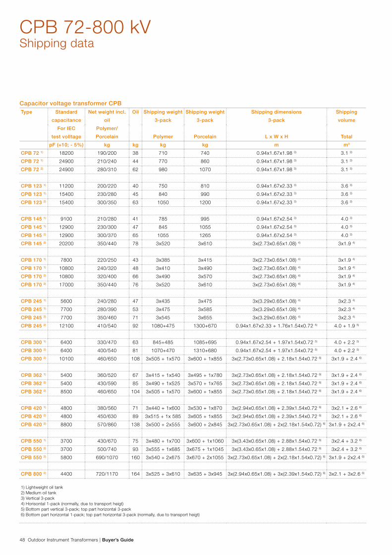
48 Outdoor Instrument Transformers | Buyer’s Guide
CPB 72-800 kVShipping data
Capacitor voltage transformer CPBType Standard
capacitance
Net weight incl.
oil
Oil Shipping weight
3-pack
Shipping weight
3-pack
Shipping dimensions
3-pack
Shipping
volume
For IEC
test volltage
Polymer/
Porcelain Polymer Porcelain L x W x H Total
pF (+10; - 5%) kg kg kg kg m m3
CPB 72 1) 18200 190/200 38 710 740 0.94x1.67x1.98 3) 3.1 3)
CPB 72 1) 24900 210/240 44 770 860 0.94x1.67x1.98 3) 3.1 3)
CPB 72 2) 24900 280/310 62 980 1070 0.94x1.67x1.98 3) 3.1 3)
CPB 123 1) 11200 200/220 40 750 810 0.94x1.67x2.33 3) 3.6 3)
CPB 123 1) 15400 230/280 45 840 990 0.94x1.67x2.33 3) 3.6 3)
CPB 123 2) 15400 300/350 63 1050 1200 0.94x1.67x2.33 3) 3.6 3)
CPB 145 1) 9100 210/280 41 785 995 0.94x1.67x2.54 3) 4.0 3)
CPB 145 1) 12900 230/300 47 845 1055 0.94x1.67x2.54 3) 4.0 3)
CPB 145 2) 12900 300/370 65 1055 1265 0.94x1.67x2.54 3) 4.0 3)
CPB 145 2) 20200 350/440 78 3x520 3x610 3x(2.73x0.65x1.08) 4) 3x1.9 4)
CPB 170 1) 7800 220/250 43 3x385 3x415 3x(2.73x0.65x1.08) 4) 3x1.9 4)
CPB 170 1) 10800 240/320 48 3x410 3x490 3x(2.73x0.65x1.08) 4) 3x1.9 4)
CPB 170 2) 10800 320/400 66 3x490 3x570 3x(2.73x0.65x1.08) 4) 3x1.9 4)
CPB 170 2) 17000 350/440 76 3x520 3x610 3x(2.73x0.65x1.08) 4) 3x1.9 4)
CPB 245 1) 5600 240/280 47 3x435 3x475 3x(3.29x0.65x1.08) 4) 3x2.3 4)
CPB 245 1) 7700 280/390 53 3x475 3x585 3x(3.29x0.65x1.08) 4) 3x2.3 4)
CPB 245 2) 7700 350/460 71 3x545 3x655 3x(3.29x0.65x1.08) 4) 3x2.3 4)
CPB 245 2) 12100 410/540 92 1080+475 1300+670 0.94x1.67x2.33 + 1.76x1.54x0.72 5) 4.0 + 1.9 5)
CPB 300 1) 6400 330/470 63 845+485 1085+695 0.94x1.67x2.54 + 1.97x1.54x0.72 5) 4.0 + 2.2 5)
CPB 300 2) 6400 400/540 81 1070+470 1310+680 0.94x1.67x2.54 + 1.97x1.54x0.72 5) 4.0 + 2.2 5)
CPB 300 2) 10100 460/650 108 3x505 + 1x570 3x600 + 1x855 3x(2.73x0.65x1.08) + 2.18x1.54x0.72 6) 3x1.9 + 2.4 6)
CPB 362 1) 5400 360/520 67 3x415 + 1x540 3x495 + 1x780 3x(2.73x0.65x1.08) + 2.18x1.54x0.72 6) 3x1.9 + 2.4 6)
CPB 362 2) 5400 430/590 85 3x490 + 1x525 3x570 + 1x765 3x(2.73x0.65x1.08) + 2.18x1.54x0.72 6) 3x1.9 + 2.4 6)
CPB 362 2) 8500 460/650 104 3x505 + 1x570 3x600 + 1x855 3x(2.73x0.65x1.08) + 2.18x1.54x0.72 6) 3x1.9 + 2.4 6)
CPB 420 1) 4800 380/560 71 3x440 + 1x600 3x530 + 1x870 3x(2.94x0.65x1.08) + 2.39x1.54x0.72 6) 3x2.1 + 2.6 6)
CPB 420 2) 4800 450/630 89 3x515 + 1x 585 3x605 + 1x855 3x(2.94x0.65x1.08) + 2.39x1.54x0.72 6) 3x2.1 + 2.6 6)
CPB 420 2) 8800 570/860 138 3x500 + 2x555 3x600 + 2x845 3x(2.73x0.65x1.08) + 2x(2.18x1.54x0.72) 6) 3x1.9 + 2x2.4 6)
CPB 550 1) 3700 430/670 75 3x480 + 1x700 3x600 + 1x1060 3x(3.43x0.65x1.08) + 2.88x1.54x0.72 6) 3x2.4 + 3.2 6)
CPB 550 2) 3700 500/740 93 3x555 + 1x685 3x675 + 1x1045 3x(3.43x0.65x1.08) + 2.88x1.54x0.72 6) 3x2.4 + 3.2 6)
CPB 550 2) 5800 690/1070 160 3x540 + 2x675 3x670 + 2x1055 3x(2.73x0.65x1.08) + 2x(2.18x1.54x0.72) 6) 3x1.9 + 2x2.4 6)
CPB 800 2) 4400 720/1170 164 3x525 + 3x610 3x635 + 3x945 3x(2.94x0.65x1.08) + 3x(2.39x1.54x0.72) 6) 3x2.1 + 3x2.6 6)
1) Lightweight oil tank2) Medium oil tank3) Vertical 3-pack4) Horisontal 1-pack (normally, due to transport heigt)5) Bottom part vertical 3-pack; top part horizontal 3-pack6) Bottom part horizontal 1-pack; top part horizontal 3-pack (normally, due to transport heigt)
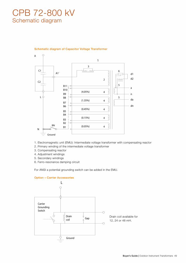
Buyer’s Guide | Outdoor Instrument Transformers 49
CPB 72-800 kVSchematic diagram
Ground
BN
1
Schematic diagram of Capacitor Voltage Transformer
1. Electromagnetic unit (EMU): Intermediate voltage transformer with compensating reactor 2. Primary winding of the intermediate voltage transformer 3. Compensating reactor 4. Adjustment windings 5. Secondary windings 6. Ferro-resonance damping circuit
For ANSI a potential grounding switch can be added in the EMU.
Option – Carrier Accessories
Drain coil available for 12, 24 or 48 mH.

50 Outdoor Instrument Transformers | Buyer’s Guide

Buyer’s Guide | Outdoor Instrument Transformers 51
CCA and CCB 72-800 kVCoupling capacitors
Coupling capacitors types CCA (standard capacitance)and CCB (extra high capacitance) are intended for power line carrier, filtering and other general capacitor applications with connection between phase and ground in high voltage networks with isolated or grounded neutral. The CCA and CCB are designed for widely shifting conditions from polar to dessert climates. The mixed dielectric in the capacitor element is subject to low stress and has proven to be insensitive to temperature changes. With regard to PLC application the CCA and CCB are suitable for use within the entire power line carrier transmission frequency range from 30 kHz to 500 kHz.
Brief performance data
Installation Outdoor
Design Column type
Insulation Aluminum-foil / paper /
polypropylene-film, synthetic oil
Highest voltage for equipment 72-800 kV
Voltage factor Fv (Vf) Up to 1.9/8 hrs
Insulators Porcelain
On request silicon rubber (SIR)
Creepage distance ≥ 25 mm/kV
(Longer on request)
Service conditions
Ambient temperature
Design altitude
-40 °C to +40 °C
(Others on request)
Maximum 1000 m
(Others on request)

52 Outdoor Instrument Transformers | Buyer’s Guide
CCA and CCB 72-800 kVCoupling capacitors
MaterialAll external metal surfaces are made of aluminium alloy resis-tant to most known environment factors. Bolts, nuts, etc. are made of acid-proof stainless steel. The aluminium surfaces do not normally need painting.
Creepage distanceAs standard, CCA and CCB are offered with creepage distance 25 mm/kV phase-phase (IEC pollution class Heavy). Longer creepage distances can be offered on request.
Silicone Rubber Insulators (SIR)The complete CCA/CCB range is available with silicone rub-ber insulators. Our SIR insulators are produced with a patent-ed helical extrusion moulding technique that gives completely joint-free insulators with outstanding performance. All CCA/CCB with this type of insulators have the same high creepage distance, 25 mm/kV phase-phase, as porcelain.
Mechanical stabilityThe mechanical stability gives sufficient safety margin for nor-mal wind loads and conductor forces.
Rating platesCorrosion resistant rating plates with laser engraved text are used. General data is to be found on the lowest capacitor unit whilst measured capacitance is marked on each capacitor unit.
Primary terminalCCA/CCB is normally delivered with a flat 4-hole aluminium pad suitable for bolts C-C from 40 to 50 mm for connecting regular aluminium cable clamps. Other primary terminals can be offered on request such as a round aluminium studs, Ø=30 mm.
Maximum static test force on the primary terminal in all direc-tions is:
− 72 kV: 500 N − 123 - 170 kV: 1000 N − 245 - 362 kV: 1250 N − 420 - 550 kV: 1500 N − 800 kV: 1300 N
Higher can be quoted on request.
Low voltage terminal/Ground clamp and support insulatorsThe coupling capacitor is normally equipped with an L-terminal/Ground clamp with a cap of nickel-plated brass for conductors 8-16 mm (area 50-200 mm2) which can be moved to either mounting side, front or rear.
A stainless steel bar terminal, 80 x 145 x 8 mm, can be quot-ed on request. The bar can be supplied undrilled or drilled according to IEC or NEMA standards.
Support insulators, for mounting the CCA/CCB insulated from the support structure (mainly for PLC application) are part of the delivery.
PLC and Line trapModern PLC equipment is adaptable for a wide range of coupling capacitors. Any specific capacitance is then not required. Only a minimum capacitance is usually specified due to choice of frequency. A line trap can in most cases be mounted directly on top of the coupling capacitor for system voltage 245 kV and below.
Special capacitancesOther capacitance values than those listed below are available on request.

Buyer’s Guide | Outdoor Instrument Transformers 53
CCA and CCB 72-800 kVInstallation and maintenance
UnpackingPlease check the crates and their contents for damage during transportation upon receipt. Should there be any damage, please contact ABB for advice before the goods are handled further. Any damage should be documented (photographed).
AssemblyThe capacitor units, whenever the coupling capacitor consists of more than one unit, are always delivered as separate units and assembled at installation.
MaintenanceThe CCA/CCB is designed for a service life of more than 30 years, and is practically maintenance-free. We recommend however, the following checks and measures.
Visual checkWe recommend a periodic inspection, to check for oil leak-ages and also to inspect the insulator for possible damage and collection of dirt.
Measurements of the capacitor unitsSince the capacitor units are permanently sealed under slight over pressure it is not possible to take oil samples from them. Under normal service conditions, no noticeable ageing will oc-cur within the capacitors (verified by ageing tests). However, periodic measurement of the capacitance value and dissipa-tion factor may still be carried out in order to verify stable con-ditions of the capacitor units. Readings are taken between the top and L-terminal/Ground clamp.
Environmental aspects
ImpregnantFaradol 810 (the synthetic oil in the capacitor units) is free from PCB and other strongly harmful substance and poses low impact to the environment.
DestructionAfter draining the oil, it can be burnt in an appropriate plant. In this respect Faradol has similar combustion properties as normal mineral oil. The disposal should be carried out in ac-cordance with local legal requirements and regulations. The porcelain can be deposited after it has been crushed.
Aluminium parts are labelled with material specifications. The metals in the housings of the capacitor units can be recycled. Regarding the aluminium in the capacitor elements, with their combination of foil, paper and polypropylene film, it can be recycled after the insulation has been burnt; the plastic film will not emit any harmful substances during this process.

54 Outdoor Instrument Transformers | Buyer’s Guide
CCA and CCB 72-800 kVTechnical data
CCA: Number of capacitor units, capacitance, total height, flashover and creepage distance
Minimum nominal values
Type Number of
capacitor units
Standard
capacitance
A
Total height
Flashover distance
Polymer/porcelain
Creepage
distance
Protected
creepage distance
Poreclain with
extra long creepage
distanceCCA CCA CCA CCA CCA
pF (+10; -5%) mm mm mm mm
CCA 72 1 23500 1140 675/700 2200 890
Offered on request.
Normally insulator as
for the nearest higher
voltage
CCA 123 1 14500 1420 955/980 3160 1282
CCA 145 1 12600 1630 1165/1190 3880 1545
CCA 170 1 10500 1840 1375/1400 4600 1835
CCA 245 1 7500 2400 1935/1960 6510 2610
CCA 300 2 6300 3170 2330/2380 7760 3090
CCA 362 2 5200 3590 2750/2800 9200 3670
CCA 420 2 4700 4010 3170/3220 10630 4250
CCA 550 2 3500 4990 4150/4200 13980 5610
CCB: Number of capacitor units, capacitance, total height, flashover and creepage distance
Minimum nominal values
Type Number of
capacitor units
Extra high
capacitance
A
Total height
Flashover distance
Polymer/porcelain
Creepage
distance
Protected
creepage distance
Poreclain with
extra long creepage
distanceCCB CCB CCB CCB CCB
pF (+10; -5%) mm mm mm mm
CCB 145 1 18900 1840 1375/1400 4600 1835
Offered on request.
Normally insulator as
for the nearest higher
voltage
CCB 170 1 15700 1840 1375/1400 4600 1835
CCB 245 1 11300 2540 2075/2100 6990 2805
CCB 300 2 9400 3590 2750/2800 9200 3670
CCB 362 2 7900 3590 2750/2800 9200 3670
CCB 420 2 7100 4010 3170/3220 10630 4250
CCB 550 2 5200 4990 4150/4200 13980 5610
CCB 800 3 3500 7440 6225/6300 20970 8415
Test voltages: IEC 60358
Type Highest voltage
for equipment
(Um)
1min
wet/dry
LIWL
1.2/50 μs
Switching impulse
250/2500 μs
PD test
voltage
Max.
PD level
RIV test
voltage
RIV level
kV kV kV kV kV pC kV Max. μV
CCA 72 72.5 140/140 325 - 1.1 x Um/√3 10 - -
CCA 123 123 230/230 550 - 1.1 x Um/√3 10 78 ≤ 2500
CCA/CCB 145 145 275/275 650 - 1.1 x Um/√3 10 92 ≤ 2500
CCA/CCB 170 170 325/325 750 - 1.1 x Um/√3 10 108 ≤ 2500
CCA/CCB 245 245 460/460 1050 - 1.1 x Um/√3 10 156 ≤ 2500
CCA/CCB 300 300 - /460 1050 850 1.1 x Um/√3 10 191 ≤ 2500
CCA/CCB 362 362 - /510 1175 950 1.1 x Um/√3 10 230 ≤ 2500
CCA/CCB 420 420 - /630 1425 1050 1.1 x Um/√3 10 267 ≤ 2500
CCA/CCB 550 550 - /680 1550 1175 1.1 x Um/√3 10 349 ≤ 2500
CCB 800 765 - /975 2100 1550 1.1 x Um/√3 10 486 ≤ 2500Test voltages above are valid for altitudes ≤ 1000 meters above sea level.

Buyer’s Guide | Outdoor Instrument Transformers 55
CCA and CCB 72-800 kVDimensions
CCA / CCB 72 - 245 CCA / CCB 300 - 800
410
410
D=366
A
D=366A
215
L-terminal/Ground clamp with a cap of nickel-plated brass for conductors 8-16 mm (area 50-200 mm2)
Note! The number of capacitor units can, for some voltages, be higher than in the drawings above. Please check in the table on page 54.

56 Outdoor Instrument Transformers | Buyer’s Guide
CCA and CCB 72-800 kVShipping data
Coupling Capacitors CCA
Type Net weight incl. oil Oil Shipping weight
3-pack
Shipping dimensions
3-pack
Shipping volume
3-pack/Total
kg kg kg LxWxH m3
CCA 72 140 17 565 1.33 x 1.55 x 0.80 1.61)
CCA 123 170 18 675 1.61 x 1.55 x 0.80 2.01)
CCA 145 190 21 735 1.82 x 1.55 x 0.80 2.31)
CCA 170 220 22 825 2.03 x 1.55 x 0.80 2.51)
CCA 245 280 27 1060 2.59 x 1.55 x 0.80 3.21)
CCA 300 370 41 730 + 670 2 x (1.8 2 x 1.55 x 0.80) 2.3 + 2.32)
CCA 362 410 44 810 + 750 2 x (2.03 x 1.55 x 0.80) 2.5 + 2.52)
CCA 420 460 49 895 + 835 2 x( 2.24 x 1.55 x 0.80) 2.8 + 2.82)
CCA 550 560 55 1095 + 1035 2 x (2.79 x 1.55 x 0.80) 3.5 + 3.52)
Coupling Capacitors CCB
Type Net weight incl. oil Oil Shipping weight
3-pack
Shipping dimensions
3-pack
Shipping volume
3-pack/Total
kg kg kg LxWxH m3
CCB 145 250 23 930 2.03 x 1.55 x 0.80 2.51)
CCB 170 250 18 930 2.03 x 1.55 x 0.80 2.51)
CCB 245 340 25 1220 2.79 x 1.55 x 0.80 3.51)
CCB 300 480 46 925 + 865 2 x (2.03 x 1.55 x 0.80) 2.5 + 2.52)
CCB 362 480 37 925 + 865 2 x (2.03 x 1.55 x 0.80) 2.5 + 2.52)
CCB 420 540 41 1015 + 955 2 x (2.24 x 1.55 x 0.80) 2.8 + 2.82)
CCB 550 660 43 1260 + 1200 2 x (2.79 x 1.55 x 0.80) 3.5 + 3.52)
CCB 800 990 65 1260 + 1200 + 1200 3 x (2.79 x 1.55 x 0.80) 3.5 + 3.5 + 3.53)
1) Normally, coupling capacitors are packed in horizontal 3-pack 2) Top and bottom parts are packed in separate cases, both of which horizontal 3-pack3) Top, middle and bottom parts are packed in separate cases, all of which horizontal 3-pack

Buyer’s Guide | Outdoor Instrument Transformers 57
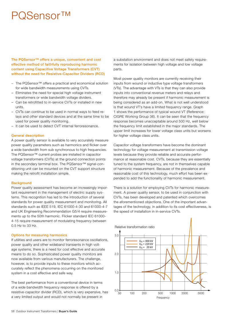
58 Outdoor Instrument Transformers | Buyer’s Guide
PQSensor™
The PQSensor™ offers a unique, convenient and cost effective method of faithfully reproducing harmonic content using Capacitive Voltage Transformers (CVT) without the need for Resistive-Capacitor Dividers (RCD)
− The PQSensor™ offers a practical and economical solution for wide bandwidth measurements using CVTs.
− Eliminates the need for special high voltage instrument transformers or wide bandwidth voltage dividers.
− Can be retrofitted to in-service CVTs or installed in new units.
− CVTs can continue to be used in normal ways to feed re-lays and other standard devices and at the same time to be used for power quality monitoring.
− It can be used to detect CVT internal ferroresonance.
General descriptionA power quality sensor is available to very accurately measure power quality parameters such as harmonics and flicker over a wide bandwidth from sub synchronous to high frequencies. The PQSensor™ current probes are installed in capacitor voltage transformers (CVTs) at the ground connection points in the secondary terminal box. The PQSensor™ signal-con-ditioning unit can be mounted on the CVT support structure making the retrofit installation simple.
BackgroundPower quality assessment has become an increasingly impor-tant requirement in the management of electric supply sys-tems. This recognition has led to the introduction of several standards for power quality measurement and monitoring. All standards such as IEEE 519, IEC 61000-4-30 and 61000-4-7 and UK Engineering Recommendation G5/4 require measure-ments up to the 50th harmonic. Flicker standard IEC 61000-4-15 require measurement of modulating frequency between 0.5 Hz to 33 Hz.
Options for measuring harmonicsIf utilities and users are to monitor ferroresonance oscillations, power quality and other wideband transients in high volt-age systems, there is a need for cost effective and accurate means to do so. Sophisticated power quality monitors are now available from various manufacturers. The challenge, however, is to provide inputs to these monitors which ac-curately reflect the phenomena occurring on the monitored system in a cost effective and safe way.
The best performance from a conventional device in terms of a wide bandwidth frequency response is offered by a resistive-capacitor divider (RCD), which is very expensive, has a very limited output and would not normally be present in
a substation environment and does not meet safety require-ments for isolation between high voltage and low voltage parts.
Most power quality monitors are currently receiving their inputs from wound or inductive type voltage transformers (VTs). The advantage with VTs is that they can also provide inputs into conventional revenue meters and relays and therefore may already be present if harmonic measurement is being considered as an add-on. What is not well understood is that wound VT’s have a limited frequency range. Graph 1 shows the performance of typical wound VT (Reference: CIGRE Working Group 36). It can be seen that the frequency response becomes unacceptable around 500 Hz, well below the frequency limit established in the major standards. The upper limit increases for lower voltage class units but worsens for higher voltage class units.
Capacitor voltage transformers have become the dominant technology for voltage measurement at transmission voltage levels because they provide reliable and accurate perfor-mance at reasonable cost. CVTs, because they are essentially tuned to the system frequency, are not in themselves capable of harmonic measurement. Because of the prevalence and reasonable cost of this technology, much effort has been ex-pended to add the functionality of harmonic measurement.
There is a solution for employing CVTs for harmonic measure-ment. A power quality sensor, to be used in conjunction with CVTs, has been developed and patented which overcomes the aforementioned objections. One of the important advan-tages of the technology, in addition to its cost effectiveness, is the speed of installation in in-service CVTs.
UN = 400 kVUN = 220 kVUN = 20 kV
50 100 200 500 1000 2000 50000.0
1.0
2.0
3.0
Relative transformation ratio
Frequency

Buyer’s Guide | Outdoor Instrument Transformers 59
PQSensor™
100
50
0
-50
-100
0 5 10 15 20 25 30 35 t (ms)
100
50
0
-50
-100
0 5 10 15 20 25 30 35 t (ms)
100
50
0
-50
-100
0 5 10 15 20 25 30 35 t (ms)
PQSensorTM
CVT Input
CVT Output
Capacitive voltage transformer cannot faithfully reproduce harmonic content on their output. Addition of PQSensor™ allows CVTs to be used in power quality and high frequency measurements.
It is as simple as Kirchoff’s law. Easy and quick to retrofit to in service CVTs.
PQSensor™ Output
C1
C2
Vc
VcVi
VoEMU
Wide bandwithoutput 0-20 mA
Signalconditioning
modulCurrentprobe 1
Currentprobe 2

60 Outdoor Instrument Transformers | Buyer’s Guide
PQSensor™Technical data
Absolute gain error 0.5% at operating frequency, measured at either outputs into 75 Ω terminations.
Gain stability over operating temperature range,
at operating frequency, (measured at “Diff Output”
with 75 Ω termination)
0.3% of full-scale output.
Gain stability over operating temperature range,
at operating frequency, (measured at the integral
output with 75 Ω termination)
0.4% of full scale output. This does not include any effects of the CVT.
Frequency response 5 Hz up to 20 kHz
Frequency response measured of “Diff Output” − 0.17 dB max at 5 kHz with respect to gain at operating frequency.
Frequency response of “Output” − 0.25 dB max. It will not have DC response.
Phase error Less than 1.5 degrees at 3 kHz and less than 3 degrees at 5 kHz. Improved phase response is
offered on request for special applications
Maximum burden 150 Ω pure resistive. This corresponds to a maximum voltage at the measurement device (e.g.
power quality monitor) of 3 V rms at a current of 20 mA. The burden may be selected to be any
value up to the maximum to suit the measurement device (the monitor). All figures related to
accuracy and error mentioned in this document would also apply for burdens up the maximum
values.
Output current levels Differential current output of 20 mA rms, driving 75 Ω through 300 meters of cable.
Cable capacitance is typically 100 pF/m.
Operating temperature range -40 to +55 °C
Power supply input voltage 48 V dc ±10% or 85-260 V dc/ac ±10%.
The unit can be supplied from the CVT nominal output of 69 V ac. Power consumption 200 mW.
Size Signal conditioning module: 10.2 x 6.3 x 3.6 inches (260 x 160 x 92 mm).
Current transformers: outer and inside diameters of 2 inches (50 mm) and .8 inches (20 mm), a
depth of .8 inches (20 mm).
Outdoor specification Conform to IP 65.
European Patent Number: EP 1295133. US Patent Number: US 6,919,717.

Buyer’s Guide | Outdoor Instrument Transformers 61

62 Outdoor Instrument Transformers | Buyer’s Guide
OptionalAccessories for cable installation
Easy installations for cablesA Roxtec CF 16 cable entry kit combines reliable sealing of cables in junction boxes with easy installations. Each CF 16 can handle several cables through the same opening.
MultidiameterThe CF 16 uses adaptable Multidiameter technology. This en-ables cables of a wide range of diameters to be sealed with a perfect fit, even when tolerances and deviations from nominal dimensions are considered. The modules are delivered with a center core as a substitute for a cable. This means the entry kit is adaptable to different cable sizes, and to different num-bers of penetrations.
Kit suppliedThe Roxtec CF 16 kits are available in two versions: Each one with a customized set of sealing modules to suit the most common cables sizes and numbers in the junction boxes (as shown below). For other dimensions, please contact: ABB, High Voltage Products, Ludvika, Sweden.
Simple maintenanceA Roxtec CF 16 can be opened and closed repeatedly for easy installations and simple maintenance. Another benefit is a built in spare capacity for possible new cables in the future.
Benefit summary − Seals several cables and diameters − Quick and easy installation − Cable retention − Rodent proof − IP 66/67 − Halogen-free − UL/NEMA 4, 4X, 12, 13 − Fire retardant material UL 94-V0
ABB CF 16 junction box kit 1 Part No.
ABB CF 16 junction box kit 2 Part No.
Roxtec CF 16 Kit 1: Handles maximum one 9.5-32.5 mm cable, two 10-25 mm cables and six 3.5-16.5 mm cables.
Roxtec CF 16 Kit 2: Handles maximum one 9.5-32.5 mm cable and four 10-25 mm cables.

Buyer’s Guide | Outdoor Instrument Transformers 63

64 Outdoor Instrument Transformers | Buyer’s Guide
ABB AB, High Voltage Products has been certified by Bureau Veritas Quality International (BVQI) to fulfill the requirements of Quality management system ISO 9001, Environmental management systems ISO 14001 and Occupational health and safety management system OHSAS 18001.
Quality control and testing
Routine tests for current transformers IMB
IEC 60044-1 clause 6.2a. Verification of terminal marking and polarity
b. Power-frequency withstand test on primary winding
c. Partial discharge measurement
d. Power-frequency withstand test on secondary windings
e. Power-frequency withstand test between winding sections
f. Inter-turn overvoltage test on secondary windings
g. Determination of errors (One transformer in each batch is type-tested for accuracy. Remaining units at a reduced number of burdens. Complete error curves on all transformers must be ordered separately.)
IEC 60044-1 clause 6.3Measurement of capacitance and tan delta
ABB specific testsa. Sealing test
b. Measurement of secondary resistance (sample)
c. Complete excitation curve for each type of core in a transformer. For the remaining transformers all cores are checked at one or two points on the excitation curve.
Routine tests for inductive voltage transformers EMF
IEC 60044-2 a. Verification of terminal marking and polarity
b. Power-frequency withstand test on primary winding (applied test, 75 Hz for one minute)
c. Partial discharge measurement
d. Power-frequency withstand test on secondary windings (applied test 4 kV, 50 Hz for one minute)
e. Determination of errors
ABB specific testsa. Sealing test
b. Measurement of no load current I0 at √3 x rated voltage
Other standardsThe tests described above also fully satisfy other standards, such as IEEE.
Type testsThe type tests reports for tests performed on transformers types similar to customer specifications are available.
Routine testsThe following tests are performed on each transformer as standard before delivery in accordance with applicable stan-dards:

Buyer’s Guide | Outdoor Instrument Transformers 65
Routine tests for capacitor voltage transformers CPB
IEC 60044-5, § 8.2 Electromagnetic unit: e, f, g, h, j Capacitor Voltage Divider/Coupling Capacitor: a, b, c, d, g Capacitor Voltage Transformer: i, j
a. Tightness of capacitor voltage divider (10.1)
b. Capacitance and tan delta measurement at power-frequency (9.2)
c. Power-frequency withstand test (10.2)
d. Measurement of partial discharge (10.2.3)
e. Verification of terminal markings (10.3)
f. Power-frequency withstand tests on the electromagnetic unit (10.4)
g. Power-frequency withstand test on low voltage terminal (10.2.4)
h. Power-frequency withstand tests on secondary windings (10.4.2)
i. Ferro-resonance check (10.5)
j. Accuracy check (determinations of errors) (10.6)
ABB specific tests: Electromagnetic unit − Sealing test − Inspection of damping circuit.
Routine tests for capacitor voltage transformers CPB and Electromagnetic unit ANSI C93.1-1999, § 6.3
* Sealing test
2.2.1 Dielectric test of primary winding, four times perfor-mance reference voltage (1 min.)
* Partial discharge measurement
2.2.3 Dielectric test on secondary windings and adjustment windings, 4 kV (1 min.)
* Dielectric test of low voltage terminal, 10 kV (1 min.)
* Inspection and measurement of the damping circuit
6. Verification of terminal marking and polarity.
5. Accuracy test
Capacitor Voltage Divider/Coupling CapacitorANSI C93.1-1999, § 6.3* Sealing test
1.1 Measurement of capacitance and dissipation factor for each capacitor unit before dielectric test
2.1 Dielectric test, voltage according to table above
* Partial discharge test of each capacitor porcelain
1.2 Capacitance and dissipation factor measurement after dielectric test
* Dielectric test of low voltage terminal (1 min.)
*) ABB-special quality check
Test capabilities in Ludvika Our high resource laboratories (high power/ high voltage/en-vironmental) in Ludvika are members of SATS (Scandinavian Association for Testing of Electric Power Equipment). SATS is a member of STL (Short Circuit Testing Liaison). STL provides a forum for international collaboration between testing organizations.
The membership and supervision of SATS ensures the inde-pendency of the laboratory. We are, with these testing resources, able to claim that we are at the forefront in developing new and safe products for the 21st century.

66 Outdoor Instrument Transformers | Buyer’s Guide
Ordering data
Current transformer IMB
The following information is required with your order: − Quantity − Standard/Customer specification − Frequency − Highest voltage for equipment − Rated insulation level
Test voltages − Lightning impulse 1.2/50 µs − Power frequency dry/wet − Switching surge 250/2500 µs (For Um ≥ 300 kV, wet)
Currents − Ratio (primary and secondary currents) − Reconnection (primary or/and secondary) − Rated continuous thermal current (Rf) − Short time current, Ith 1 sec (3 sec) − Dynamic current, Idyn
Burden and accuracy − Number of cores − For each core please state: − Burden/class/overcurrent factor
Special requirements − Silicone rubber insulator (gray) − Creepage distance (ABB standard: 25 mm/kV) − Light gray porcelain (ABB standard: brown) − Special primary terminals − Special secondary terminals − Heater − Secondary overvoltage protection:
(spark gaps, protection gaps) − Anodized tank, terminal box and expansion system
(IMB 36-170) − 1-pack, vertical transport (IMB 36-145) − Horizontal transport (IMB 36-145) − Other?
Additional requirements − Capacitive voltage tap − Adapter (for replacing old type IMB) − Ambient temperature − Height above sea level if >1000 m
Please state “normal” system and test voltages according to actual standard when ≤1 000 m a.s.l.
− Other requirements?
Voltage transformer EMF
The following information is required with your order: − Quantity − Standard/Customer specification − Frequency − Highest voltage for equipment − Rated insulation level
Test voltages − Lightning impulse 1.2/50 µs − Power frequency dry/wet
Voltages − Ratio (primary and secondary voltages) − Reconnection (secondary) − Voltage factor (Vf) and time
Burden and accuracy − Number of secondary winding(s) − For each winding please state:
Connection: Star or broken delta Burden/class
− Thermal limit burden (if requested)
Special requirements − Silicone rubber insulator (gray) − Creepage distance (ABB standard: 25 mm/kV) − Light gray porcelain (ABB standard: brown) − Special primary terminal − Special secondary terminals − Secondary fuses − Heater − Anodized tank, terminal box and expansion system − 1-pack vertical transport (EMF 52-84) − 1-pack, horizontal transport (EMF 123-170) − Other requirements?
Additional requirements − Ambient temperature − Height above sea level if >1000 m
Please state “normal” system and test voltages according to actual standard when ≤1 000 m a.s.l.
− Other requirements?
Buyer’s Guide | Outdoor Instrument Transformers 67
Capacitor Voltage Transformer CPB
The following information is required with your order: − Quantity − Standard/Customer specification − Frequency − Highest voltage for equipment − Rated insulation level
Test voltages − Lightning impulse 1.2/50 µs − Power frequency dry/wet − Switching surge 250/2500 µs (For Um ≥ 300 kV, wet)
Voltages − Ratio (primary and secondary voltages) − Reconnection (secondary) − Voltage factor FV (Vf) and time
Burden and accuracy − Number of secondary winding (s) − For each winding please state:
Connection: Star or broken delta Burden/class
− Thermal limit burden (if requested)
Special requirements − Silicone rubber insulator (gray) − Creepage distance (ABB standard: 25 mm/kV) − Light gray porcelain (ABB standard: brown) − Special primary terminal − Special secondary terminals − Secondary fuses − Heater − Protection for PLC equipment − Horizontal transport − Other requirements?
Additional requirements − Capacitance - high or extra high − Ambient temperature − Height above sea level if >1000 m
Please state “normal” system and test voltages according to actual standard when ≤1 000 m a.s.l.
− Other requirements?
Coupling Capacitor CCA and CCB
The following information is required with your order: − Quantity − Standard/Customer specification − Frequency − Highest voltage for equipment − Rated insulation level
Test voltages − Lightning impulse 1.2/50 µs − Power frequency dry/wet − Switching surge 250/2500 µs (For Um ≥ 300 kV, wet)
Special requirements − Silicone rubber insulator (gray) − Creepage distance (ABB standard: 25 mm/kV) − Light gray porcelain (ABB standard: brown) − Special primary terminal
Additional requirements − Capacitance - high or extra high − Ambient temperature − Height above sea level if >1 000 m
Please state “normal” system and test voltages according to actual standard when ≤1 000 m a.s.l.
− Other requirements?

Contact us
Pub
licat
ion
1HS
M 9
543
42-0
0en,
Edi
tion
6, 2
009-
12 O
utdo
or In
stru
men
t Tra
nsfo
rmer
s, B
uyer
’s G
uide
, Pho
to: H
asse
Erik
sson
ABB AB High Voltage Products
SE-771 80 LUDVIKA, SWEDENPhone: +46 (0)240 78 20 00 Fax: +46 (0)240 78 36 50 E-Mail: [email protected] www.abb.com
©Copyright 2009 ABB
All right reserved
NOTE! ABB AB is working continuously to improve
the products. We therefore reserve the right to change
designs, dimensions and data without prior notice.


![Welcome [iiee.org.ph]iiee.org.ph/.../Ritz-Instrument-Transformers-GmbH.pdf · Ritz Instrument Transformers GmbH Welcome. ... Metal-enclosed Instrument Transformers ... application](https://static.fdocuments.in/doc/165x107/5a7fecbc7f8b9a0c748bfecf/welcome-iieeorgphiieeorgphritz-instrument-transformers-gmbhpdfritz-instrument.jpg)