
A 52 Amplifier2 - · PDF filePARASOUND A 52 DESIGN OVERVIEW 16 PARASOUND A 52 SPECIFICATIONS...
21
A 52 Amplifier Owner’s Guide
-
Upload
truongkhue -
Category
Documents
-
view
216 -
download
1
Transcript of A 52 Amplifier2 - · PDF filePARASOUND A 52 DESIGN OVERVIEW 16 PARASOUND A 52 SPECIFICATIONS...

A 52 Amplifier Owner’s Guide
THANK YOU!
Congratulations and Thank You for Choosing ParasoundYour new Parasound Halo Series A 52 power amplifier presents the latest advancements inamplifier technology. The A 52 is built to the strict quality and performance standards set byParasound. We’re proud to offer you this exceptional audio component that will bring you manyyears of enjoyment and dependability.
Here at Parasound, we design our products to perform at a higher level of flexibility and sonicperformance than you may have expected. We encourage you to read this entire manual tolearn all the features and capabilities of your new Halo Series A 52 Amplifier.
If you’re eager to get up and running right away, simply follow the basic step-by-step instruc-tions to connect and operate the A 52. If you want to learn about some of the technical anddesign aspects of your A 52, refer to the Technically Speaking and Parasound A 52 DesignOverview sections in the back of the manual. If you run into difficulties, the TroubleshootingGuide should help you quickly remedy the problem.
We appreciate you taking the time to read these instructions and thank you for selectingParasound for your listening pleasure.
The Parasound Staff
Unpacking Your A 52Unpack your A 52 from the shipping carton, remove the AC power cord and the control wire with a 2.5 mm sub-mini plug on each end. (This is the trigger connection wire). While you areunpacking your new amplifier, inspect it thoroughly for possible shipping damage. If you see any,contact your Parasound dealer right away. Be sure to save and store both the inner and outer cartons and the packing inserts for possible future transport. To save room for storage, you cancut the seams on the bottom of the cartons and flatten them.
Keeping Records for Future ReferenceRecord the serial number located on the bottom of your A 52 in the space below. Also note your Parasound Dealer’s name and phone number. We recommend that you keep your purchasereceipt with this manual and store them both in a safe place. You may need to refer to this information sometime in the future.
Parasound A 52 Amplifier Serial #: __________________________________________________
Parasound Dealer: ________________________________________________________________
Phone Number: __________________________________________________________________
Date of Purchase: ________________________________________________________________
YOU SHOULD KNOWThere is no Parasound warranty for this unit if it was not purchased from an AuthorizedParasound Dealer. Investigate any warranty claims made by unauthorized dealers very carefully as you will need to depend entirely upon the dealer, and NOT upon Parasound.Unauthorized dealers may lack the capability to arrange repairs of Parasound equipment.Authorized Parasound Dealers are listed at www.parasound.com or you can call 415-397-7100 between 8:30 am and 4:30 pm Pacific time.
A missing or tampered serial number could indicate that this unit was stolen or sold by an unauthorized dealer. If this unit is missing its serial number, you should return it to your dealer immediately for a full refund.

TABLE OF CONTENTS
A 52 Amplifier
PLACEMENT GUIDELINES FOR YOUR A 52 2
CONNECTING A SURROUND CONTROLLER TO THE BALANCED INPUTS ON YOUR A 52 3
CONNECTING A SURROUND CONTROLLERTO THE UNBALANCED INPUTS ON YOUR A 52 4
CONNECTING YOUR SPEAKERS TO THE A 52 5
MANUAL AND AUTOMATIC TURN ON-OFF OPTIONS 6
CONNECTING AN EXTERNAL DC SOURCE FOR AUTOMATIC ON-OFF 7
CONNECTING THE A 52 TO TRIGGER ANOTHER COMPONENT 8
UNDERSTANDING THE INDICATORS ON THE A 52 9
CONNECTING THE AC POWER CORD 10
MAINTAINING YOUR A 52 11
TROUBLESHOOTING GUIDE 12
SERVICING YOUR A 52 13
TECHNICALLY SPEAKING 14
PARASOUND A 52 DESIGN OVERVIEW 16
PARASOUND A 52 SPECIFICATIONS 18

PLACEMENT GUIDELINES FOR YOUR A 52
Power amplifiers are usually heavier and generate more heat than other components. To avoiddamage to the A 52 or other equipment and to reduce risk of fire, you must follow these guidelines:
• Place the A 52 on a separate shelf that will adequately support its weight.• Keep it away from heat sources such as air ducts or radiators.• Avoid placing it on carpeting or another material that might obstruct airflow into the
openings in the chassis bottom.• Leave at least 3" of space around both sides and 6" of space above the top. The bottom
clearance can be a little less. • Do not block the front of the A 52 behind closed cabinet doors during use.• Do not stack the A 52 with other components inside a cabinet unless you use a fan
to circulate and exhaust the warm air that builds up between them.
Rack Mounting Your Parasound A 52To mount the A 52 into a 19" wide equipment rack, you must first attach its HRA 3 rack mountbrackets (not included). With its four feet removed, the A 52 chassis and front panel height occu-pies three rack spaces (5 1⁄4" or 133 mm). When mounting equipment below the A 52, you will also need to allow about 1⁄8" below the unit for the bottom chassis screws. A single standard rackspace allows 1 3⁄4" vertical height in a 19" wide equipment rack. This measurement standard wasdeveloped by the EIA (Electronic Industries Association) so manufacturers of electronic compo-nents and equipment racks could build products in standardized heights that would fit in a uniformspace. Please call your Parasound dealer or Parasound Technical Services if you need additionaladvice about rack mounting the A 52.
To attach the rack mount brackets:• Remove the two screws from each side of the A 52’s top cover. • Line up the two holes on each HRA 3 bracket with these holes on the A 52 and attach
the brackets with the longer screws that are in the bracket kit. • Make sure the screws are tight because they will support the entire weight of the A 52
in the equipment rack.
2
L U C A S F I L M
On-Off Hi Temp
HRA 3 Rack Bracket

CONNECTING A SURROUND CONTROLLER TO THE BALANCED INPUTS ON YOUR A 52
Left and Right Balanced Input JacksBalanced connections will give you the best sound. If your surround controller has balanced XLR output jacks, we recommend that you connect them to these inputs. Refer to the Balancedand Unbalanced Lines in the Technically Speaking section for additional information about whywe recommend using balanced lines.
What You’ll Need:• Five balanced interconnect cables with XLR connectors• A surround controller with balanced output connectors
Before Connecting❑ Leave the A 52’s AC cord disconnected until you have made all other connections to prevent
any surprise burst of sound.❑ Make sure that all your cables are long enough so they are not strained or stretched
once they are connected.❑ Make sure the Balanced - Unbalanced Inputs selector switch on the rear of the A 52 is
in its Balanced (upper) position. The Ground switch should be in its Normal (lower) position.
To Connect1 Plug the male end of the first balanced interconnect cable into the Balanced Ch 1 input
jack on the A 52.
2 Plug the female end of the cable into the balanced output jack for the channel on your surround controller that you wish to correspond to Ch 1 on your A 52.
3 – 0 Repeat steps 1 and 2 above to connect Ch 2, Ch 3, Ch 4, and Ch 5.
3
YOU SHOULD KNOW
Balanced XLR Jacks and Their Pin ConfigurationThe balanced inputs of the A 52 use XLR jacks that conform to the industry standard of:Pin 1: Ground, Pin 2: Positive (+), Pin 3: Negative (–). The balanced outputs on some com-ponents use terminals with 3 screws instead of XLR jacks. These are compatible with theA 52 as long as you match the bare wires to the corresponding pins on the XLR plug: + topin 2, - to pin 3, and Ground to pin 1.
XLR Connectors
Male
Female
SURROUNDŁCONTROLLER
OUTPUTS
Ch 1 Ch 2 Ch 3 Ch 4 Ch 5
InputBalanced
UnbalancedInput
Balanced
UnbalancedInput
Balanced
UnbalancedInput
Balanced
UnbalancedInput
Balanced
Unbalanced
Man
Balanced
Inputs
Unbalanced Input 12 VOutput
Audio Sensitivity
50 mV 250
Ground
Normal
Lift
WARNINGTo Prevent Fire Or Shock Hazard,Do Not Expose This Unit To Rain
Or Moisture.
FuseT15A/250V1-115V AreaT8A/250V-230V Area
AC 115V 60HzAC 230V 50Hz
Power Consumption: 1350W
Parasound Products, Inc.San Francisco, CA USA
Manufactured underlicense from LucasfilmLtd. Lucasfilm and THX
are registered Trademarksof Lucasfilm Ltd.
CAUTIONTo Prevent Electric Shock, Do Not
Remove Cover. No User-ServiceableParts Inside, Refer Servicing To
Qualified Service Personnel.
Auto Turn On
L U C A S F I L ML M
1 3 5 7 9
2 4 6 8 10
Ground Switch, set to down position
Inputs Switch, set to up position

CONNECTING A SURROUND CONTROLLER TO THE UNBALANCED INPUTS ON YOUR A 52
4
Ch 1-5 Unbalanced InputsUse these inputs if your surround controller doesn’t have balanced output connectors or if yousimply prefer to use unbalanced connections.
What You’ll Need:• Five shielded interconnect cables with RCA plugs• A surround controller with five RCA output jacks
Before Connecting❑ Leave the AC cord on the A 52 disconnected until you have made all other connections
to prevent any surprise burst of sound.❑ Make sure that all your cables are long enough so they are not pulled or stretched
once they are connected.❑ Make sure the Balanced-Unbalanced Inputs selector switch on the A 52 is in its
Unbalanced (lower) position and the Ground switch is in its Normal (lower) position.
To Connect1 Plug one end of the cable into the Unbalanced Ch 1 Input jack on the A 52.2 Plug the other end of the cable into the unbalanced output jack for the channel
on your surround controller that you wish to correspond to Ch 1 on your A 52.
3 – 0 Repeat steps 1 and 2 for Ch 2, Ch 3, Ch 4, and Ch 5.
YOU SHOULD KNOW
Write Down Your Connections Make a note of which channel on your surround controller now connects to each channelof the A 52 so you’ll always hear the channels in their intended position and to facilitatetrouble-shooting in case you encounter a problem later on.
SURROUNDŁCONTROLLER
OUTPUTS
2 4 6 8 10
Ch 1 Ch 2 Ch 3 Ch 4 Ch 5
InputBalanced
UnbalancedInput
Balanced
UnbalancedInput
Balanced
UnbalancedInput
Balanced
UnbalancedInput
Balanced
Unbalanced
Man
Balanced
Inputs
Unbalanced Input 12 VOutput
Audio Sensitivity
50 mV 250
Ground
Normal
Lift
WARNINGTo Prevent Fire Or Shock Hazard,Do Not Expose This Unit To Rain
Or Moisture.
FuseT15A/250V1-115V AreaT8A/250V-230V Area
AC 115V 60HzAC 230V 50Hz
Power Consumption: 1350W
Parasound Products, Inc.San Francisco, CA USA
Manufactured underlicense from LucasfilmLtd. Lucasfilm and THX
are registered Trademarksof Lucasfilm Ltd.
CAUTIONTo Prevent Electric Shock, Do Not
Remove Cover. No User-ServiceableParts Inside, Refer Servicing To
Qualified Service Personnel.
Auto Turn On
L U C A S F I L ML M
1 3 5 7 9
Ground Switch, set to down position
Inputs Switch, set to down position
RCA Plugs

CONNECTING YOUR SPEAKERS TO THE A 52 5
StrippedAWG wire
DualBanana Plug
Common Speaker Connectors
SingleBanana Plug
Spade Lug
Speaker TerminalsThe A 52 speaker terminals accept speaker wires with banana plugs, spade lugs, or bare ends. Refer to Bare Wire Speaker Termination in the Technically Speaking section for information about bare wire termination.
What You’ll Need:• Five lengths of AWG 16 or thicker speaker wire
with banana plugs, spade lugs, or bare ends• Five loudspeakers
Before Connecting❑ Remove power to all the components in your audio system.
To ConnectWhen connecting your speakers you need to keep in mind which channel of the A 52 you connected to each channel on your surround controller. You can write these down on page 10.1 Insert one wire with the ridge or other marking into the red Ch 1 + (positive) speaker
terminal on the A 52. Insert the wire without the ridge or other marking into the black Ch 1 - (negative) speaker terminal.
2 Insert the other end of the wire with the ridge or other marking to the red + (positive) terminal on the speaker. Insert the other end of the wire without the ridge or other marking to the adjacent black – (minus) terminal on the speaker.
3 – 0 Repeat steps 1 and 2 for Ch 2, then Ch 3, then Ch 4, and finally Ch 5.
YOU SHOULD KNOW
Correct Speaker Polarity is ImportantPolarity refers to + and – connections. Speaker wires are coded with printing or a ridge on theinsulation on one of the leads so you know which lead was connected to the + and – terminalsat the other end. This coding will help you keep the + and - polarity consistent for all channels.
Speaker Wire Length and Gauge (thickness)When selecting speaker wire, follow these guidelines:
• Keep the length of your speaker wire as short as possible.• Use the thickest wire practical. For lengths greater than 50 feet, use speaker wire
with an AWG (gauge) of 14 or lower. The smaller the AWG, the thicker the wire.• Do not use speaker wire that is thinner than 16 AWG.• Keep wire lengths for both channels as close to equal as possible.
2
SPEAKERS
1 3 5 7 9
2 4 6 8 10
Ch 1 Ch 2 Ch 3 Ch 4 Ch 5
InputBalanced
UnbalancedInput
Balanced
UnbalancedInput
Balanced
UnbalancedInput
Balanced
UnbalancedInput
Balanced
Unbalanced
Man
Balanced
Inputs
Unbalanced Input 12 VOutput
Audio Sensitivity
50 mV 250
Ground
Normal
Lift
WARNINGTo Prevent Fire Or Shock Hazard,Do Not Expose This Unit To Rain
Or Moisture.
FuseT15A/250V1-115V AreaT8A/250V-230V Area
AC 115V 60HzAC 230V 50Hz
Power Consumption: 1350W
Parasound Products, Inc.San Francisco, CA USA
Manufactured underlicense from LucasfilmLtd. Lucasfilm and THX
are registered Trademarksof Lucasfilm Ltd.
CAUTIONTo Prevent Electric Shock, Do Not
Remove Cover. No User-ServiceableParts Inside, Refer Servicing To
Qualified Service Personnel.
Auto Turn On
L U C A S F I L ML M

You can manually turn the A 52 on and off with its front panel On-Off button. It can also be triggeredto turn on and off automatically when your preamplifier, surround controller, or system controller isturned on and off.
Manual On-Off from the Front PanelIf you want to manually turn on and off the A 52 at any time, you need to first select the Manual On-Off option by placing the Auto Turn On switch (on the rear panel) to its middle Man (Manual) position.
Connecting an Active Audio Source for Automatic On-Off If you want to automatically turn on the A 52 whenever music is playing (an audio signal is present),choose the audio triggering option by moving the Auto Turn On switch to its Audio (upper) position.
What You’ll Need:• An audio source that’s playing
Before Connecting❑ Remove power to all the components in your audio system.❑ Make sure the Auto Turn On switch on the A 52 is in its Audio (upper) position.❑ Set the Audio triggering Sensitivity adjustment knob on the rear panel to the desired level.
Start with the 12 o’clock position.
To ConnectConnect an active audio source to either the Ch 1 Balanced or Unbalanced Input jacks. (Refer to to pages 2 and 3).
MANUAL AND AUTOMATIC TURN ON-OFF OPTIONS6
YOU SHOULD KNOW
Turn Off Delay in the Audio ModeWhen the music stops, the A 52 will remain on for about five minutes. This delay preventsunwanted turn-off during silent passages in music or during the pauses between tracks.
Ch 1 Ch 2 Ch 3 Ch 4 Ch 5
InputBalanced
UnbalancedInput
Balanced
UnbalancedInput
Balanced
UnbalancedInput
Balanced
UnbalancedInput
Balanced
Unbalanced
Man
Balanced
Inputs
Unbalanced Input 12 VOutput
Audio Sensitivity
50 mV 250
Ground
Normal
Lift
WARNINGTo Prevent Fire Or Shock Hazard,Do Not Expose This Unit To Rain
Or Moisture.
FuseT15A/250V1-115V AreaT8A/250V-230V Area
AC 115V 60HzAC 230V 50Hz
Power Consumption: 1350W
Parasound Products, Inc.San Francisco, CA USA
Manufactured underlicense from LucasfilmLtd. Lucasfilm and THX
are registered Trademarksof Lucasfilm Ltd.
CAUTIONTo Prevent Electric Shock, Do Not
Remove Cover. No User-ServiceableParts Inside, Refer Servicing To
Qualified Service Personnel.
Auto Turn On
L U C A S F I L ML M
Auto Turn On Switch, set to up position
Ch 1 Ch 2 Ch 3 Ch 4 Ch 5
InputBalanced
UnbalancedInput
Balanced
UnbalancedInput
Balanced
UnbalancedInput
Balanced
UnbalancedInput
Balanced
Unbalanced
Man
Balanced
Inputs
Unbalanced Input 12 VOutput
Audio Sensitivity
50 mV 250
Ground
Normal
Lift
WARNINGTo Prevent Fire Or Shock Hazard,Do Not Expose This Unit To Rain
Or Moisture.
FuseT15A/250V1-115V AreaT8A/250V-230V Area
AC 115V 60HzAC 230V 50Hz
Power Consumption: 1350W
Parasound Products, Inc.San Francisco, CA USA
Manufactured underlicense from LucasfilmLtd. Lucasfilm and THX
are registered Trademarksof Lucasfilm Ltd.
CAUTIONTo Prevent Electric Shock, Do Not
Remove Cover. No User-ServiceableParts Inside, Refer Servicing To
Qualified Service Personnel.
Auto Turn On
L U C A S F I L ML M
Auto Turn On Switch, set to middle position

CONNECTING AN EXTERNAL DC SOURCE FOR AUTOMATIC TURN ON-OFF
To automatically turn on and off the A 52 with an external DC voltage, choose the DC Triggeringoption by moving the Auto Turn On switch on the rear panel to its lower 12V position.
What You’ll Need:• A cable with a 2.5 mm sub-mini plug on each end (provided)• A “control” component with +9Vdc to +12Vdc trigger voltage
Before Connecting❑ Remove Power to all the components in your audio system.❑ Make sure the Auto Turn On switch on the A 52 rear panel is in its 12V (down) position.
To Connect1 Plug one end of the trigger wire into the 12V Input jack on the A 52.2 Plug the other end of this wire into the external DC source.
7
YOU SHOULD KNOWIf the device you want to use to control your A 52 doesn’t have a 2.5 mm trigger outputconnector, you can cut one plug off the cable and terminate the end as required. The leadwith the red stripe is positive and the lead without the stripe is negative.
Output
CONTROLCOMPONENT2
1
Ch 1 Ch 2 Ch 3 Ch 4 Ch 5
InputBalanced
UnbalancedInput
Balanced
UnbalancedInput
Balanced
UnbalancedInput
Balanced
UnbalancedInput
Balanced
Unbalanced
Man
Balanced
Inputs
Unbalanced Input 12 VOutput
Audio Sensitivity
50 mV 250
Ground
Normal
Lift
WARNINGTo Prevent Fire Or Shock Hazard,Do Not Expose This Unit To Rain
Or Moisture.
FuseT15A/250V1-115V AreaT8A/250V-230V Area
AC 115V 60HzAC 230V 50Hz
Power Consumption: 1350W
Parasound Products, Inc.San Francisco, CA USA
Manufactured underlicense from LucasfilmLtd. Lucasfilm and THX
are registered Trademarksof Lucasfilm Ltd.
CAUTIONTo Prevent Electric Shock, Do Not
Remove Cover. No User-ServiceableParts Inside, Refer Servicing To
Qualified Service Personnel.
Auto Turn On
L U C A S F I L ML M
Audio Turn On Switch,set to down position
2.5 mm sub-mini plug

CONNECTING THE A 52 TO TRIGGER ANOTHER COMPONENT
Whenever the A 52 is turned on either manually or automatically, there is 12 Vdc present at its own DC Trigger Out jack so it can trigger additional amplifiers or other components on and off.
What You’ll Need:• A wire with a 2.5 mm sub-mini plug on each end (in addition
to the wire provided with the A 52)• A component that can be triggered with an external +9 Vdc to +12 Vdc
source. The A 52 DC trigger output provides up to 150 mA of current
Before Connecting❑ Remove power to all the components in your audio system.
To Connect1 Plug one end of the trigger wire into the 12V Output jack on the A 52.2 Plug the other end of this wire into the component that you want the A 52 to trigger.
8
YOU SHOULD KNOWIf the device you want your A 52 to control doesn’t have a 2.5 mm trigger output connector, you can cut one plug off the cable and terminate the end as required. The lead with the stripe is positive and the lead without the stripe is negative.
CONTROLLEDCOMPONENT
Input
2
1
Ch 1 Ch 2 Ch 3 Ch 4 Ch 5
InputBalanced
UnbalancedInput
Balanced
UnbalancedInput
Balanced
UnbalancedInput
Balanced
UnbalancedInput
Balanced
Unbalanced
Man
Balanced
Inputs
Unbalanced Input 12 VOutput
Audio Sensitivity
50 mV 250
Ground
Normal
Lift
WARNINGTo Prevent Fire Or Shock Hazard,Do Not Expose This Unit To Rain
Or Moisture.
FuseT15A/250V1-115V AreaT8A/250V-230V Area
AC 115V 60HzAC 230V 50Hz
Power Consumption: 1350W
Parasound Products, Inc.San Francisco, CA USA
Manufactured underlicense from LucasfilmLtd. Lucasfilm and THX
are registered Trademarksof Lucasfilm Ltd.
CAUTIONTo Prevent Electric Shock, Do Not
Remove Cover. No User-ServiceableParts Inside, Refer Servicing To
Qualified Service Personnel.
Auto Turn On
L U C A S F I L ML M
Auto Turn On Switch,set to down position
2.5 mm sub-mini plug

a AC Present Indication When the A 52 is plugged into a live AC outlet, a soft blue halo glows behind its On-Offbutton and its red “P” Badge glows faintly. These indicate that the unit is plugged into a liveAC outlet, even when it is turned off.
b On, Off and Fault/Protection Status Indicators Whenever the A 52 is turned on, the soft blue glow behind its On-Off button will change to red for about five seconds as its internal circuits stabilize. Then the red glow is replacedby a brighter blue glow to indicate normal operation. If the glow remains red after turn onor while the amp is playing, it indicates activation of the A 52’s protection circuits and nosound will be heard from the speakers.
The A 52 protects itself from external conditions such as excessive heat, load impedancethat is too low, or a short-circuited speaker connection or wire. After you correct the fault,the A 52 will resume operation. If the A 52 remains “in protection” after it has cooled downand you’ve confirmed there are no external faults, it could indicate an internal problem.Please contact Parasound’s Technical Service Department.
c – g Channel Status IndicatorsThese are the five small round indicators in the center of the recess in the front panel. The indicator on the left displays the status of channel one and the subsequent indicatorsdisplay the status of channels two through five.
c – g All Indicators IlluminatedWhen all five channels are operating normally, these will all glow blue.
c – g No Illumination: When the A 52 is turned off, these indicators are off. An indicator that does not glow when the A 52 is turned on represents a fault in that channel.
h High-Temp IndicatorThis indicator is near the right side of the panel recess. It will glow red if any channel overheats.The On-Off button will also glow red if the A 52 overheats and shuts down to protect itself.Refer to the Troubleshooting Guide on page 12.
UNDERSTANDING THE INDICATORS ON THE A 52 9
L U C A S F I L ML M
On-Off Hi Temp
CONNECTING THE A 52 AC POWER CORD
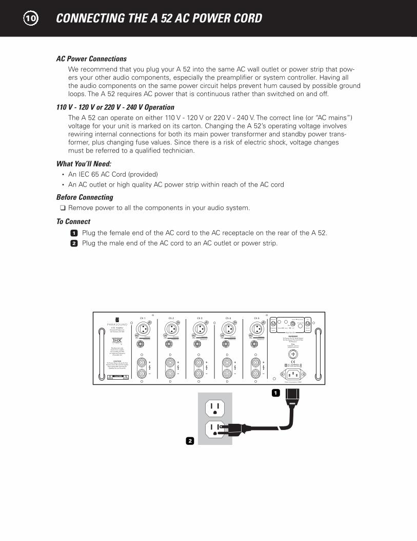
AC Power ConnectionsWe recommend that you plug your A 52 into the same AC wall outlet or power strip that pow-ers your other audio components, especially the preamplifier or system controller. Having all the audio components on the same power circuit helps prevent hum caused by possible groundloops. The A 52 requires AC power that is continuous rather than switched on and off.
110 V - 120 V or 220 V - 240 V OperationThe A 52 can operate on either 110 V - 120 V or 220 V - 240 V. The correct line (or “AC mains”)voltage for your unit is marked on its carton. Changing the A 52’s operating voltage involvesrewiring internal connections for both its main power transformer and standby power trans-former, plus changing fuse values. Since there is a risk of electric shock, voltage changes must be referred to a qualified technician.
What You’ll Need:• An IEC 65 AC Cord (provided)• An AC outlet or high quality AC power strip within reach of the AC cord
Before Connecting❑ Remove power to all the components in your audio system.
To Connect1 Plug the female end of the AC cord to the AC receptacle on the rear of the A 52.2 Plug the male end of the AC cord to an AC outlet or power strip.
10
2
1
Ch 1 Ch 2 Ch 3 Ch 4 Ch 5
InputBalanced
UnbalancedInput
Balanced
UnbalancedInput
Balanced
UnbalancedInput
Balanced
UnbalancedInput
Balanced
Unbalanced
Man
Balanced
Inputs
Unbalanced Input 12 VOutput
Audio Sensitivity
50 mV 250
Ground
Normal
Lift
WARNINGTo Prevent Fire Or Shock Hazard,Do Not Expose This Unit To Rain
Or Moisture.
FuseT15A/250V1-115V AreaT8A/250V-230V Area
AC 115V 60HzAC 230V 50Hz
Power Consumption: 1350W
Parasound Products, Inc.San Francisco, CA USA
Manufactured underlicense from LucasfilmLtd. Lucasfilm and THX
are registered Trademarksof Lucasfilm Ltd.
CAUTIONTo Prevent Electric Shock, Do Not
Remove Cover. No User-ServiceableParts Inside, Refer Servicing To
Qualified Service Personnel.
Auto Turn On
L U C A S F I L ML M

Your Parasound A 52 power amplifier requires no periodic maintenance and has no user-serviceable parts inside. To avoid the risk of electric shock, do not remove its top cover. The amplifier’s exterior can easily be cleaned with a soft cloth pre-moistened only with a fewdrops of water or glass cleaner.
Main Power FuseIf this fuse blows, please contact Parasound Technical Service for further advice.
Notes:
MAINTAINING YOUR A 52 11

TROUBLESHOOTING GUIDE12
No power
Auto turn on doesn’tfunction with a triggervoltage
Auto turn on doesn’tfunction with an audioinput signal
A52 will not turn off whenaudio signal is removed
Power on, but no sound
On-Off button glows redand channel indicator(s)off
Distorted sound
Hum and / or buzzthrough speakers
A 52 is overheating
Power cord is disconnected
Auto Turn On selector switch is in wrong position
AC fuse blown
DC trigger source wired inreverse or voltage too low
Auto Turn On selector switch is in wrong position
Auto Turn On selector switch is in wrong position
Sensitivity incorrectly adjusted
Sensitivity level too high
Bad connection from surround controller
Over-current protection circuitryhas been activated- one or moreblue channel LEDs not illuminated
A 52 has overheated - red HiTemp indicator is on
Damaged speaker
Problem with surround controller or source component
Balanced-Unbalanced Inputswitch is in the incorrect position
Ground loop between surroundcontroller and A 52 or at theequipment rack
Ground loop from cable TV
Other ground loop
Load impedance at speaker terminals is too low
Not enough ventilation
Connect power cord to a live AC outlet
Check for correct position of the Auto Turn On switch
Replace with same value fuse
Check polarity of DC source with a voltmeter. Try connecting a 9V battery to the 12V DC input
Make sure Auto Turn On selector switch is in its 12V position
Make sure Auto Turn On selector switch is in its Audio position
Turn the Audio trigger Sensitivity knob counterclockwise
Turn Sensitivity knob clockwise toward 250 mV
Check input connections or try a different set of cables
Check speaker load impedance. Check speakerwires and connections
Allow A 52 to cool. Check that there is adequateventilation around the A 52. Be sure the loadimpedance of each channel is no less than 4 ohms
Connect each speaker to another channel on theA 52. If the same speaker remains distorted, thespeaker or its wire is damaged. If the other speak-er distorts, the problem may be with the A 52, thesurround controller, or a source component
Switch the input cables. If distortion moves to another channel, the problem is with a component other than the A 52
Move to the correct position for the jacks in use
Move the Ground switch to its Lift position.Install nylon shoulder washers on both sides of the panels of all equipment to insulate metalfrom touching the rack
Move the Ground switch to its Lift position.Install a cable isolation device such as theXantech 634 Ground Breaker.www.xantech.com
Contact Parasound Technical Service
Make sure the speaker or speaker selector load is 4 ohms or higher
Make sure the A 52 has adequate ventilation
TROUBLE PROBABLE CAUSE REMEDY

If All Else Fails –Call Us for HelpCall your Parasound dealer or Parasound’s Technical Service Department toll free at 1-866-770-TECH (8324). We can often solve the problem with simple diagnostic tests you can perform yourself. If we determine that your A 52 will need further inspection or servicing, we will:
a) Refer you to an authorized Parasound repair center near you, or b) Authorize return of the unit to us and advise you of the correct procedure.
Procedure for Returning Your A 52 to Parasound for ServiceIf Parasound determines that you should send your A 52 to Parasound, you will be given a ReturnAuthorization (RA) number. This RA number must be clearly marked on the outer carton only.
IMPORTANT: Enclose a copy of your original purchase receipt. A unit is eligible for warranty
repair ONLY when the purchase receipt shows that the unit was purchased from an
Authorized Parasound Dealer. A unit obtained through unauthorized channels is not eligible for warranty repair. Parasound is not responsible for any sellers’ misrepresentations about ourwarranties or other service policies.
We do not accept any of the following:
• Units with collect shipping charges• Units without a valid RA number • Units without a suitable shipping carton• Units for which we see or hear evidence of improper packing
For a non-warranty repair, contact us for an estimate of the repair charges before you ship the unit to us. The same packing and Return Authorization number procedures apply.
Important Notice - Shipping the A 52Before shipping the unit to Parasound, you MUST re-pack the unit into its fitted molded foaminsert sandwich and its original carton. If you do not have the original packing cartons and foaminserts, call us for new packing materials that we can provide to you for a nominal charge. Use
of any other carton and packing materials will probably result in shipping damage, and
refusal of the unit. Common carriers such as UPS seldom pay claims for damage incurred during shipment when a product is surrounded only with Styrofoam “peanuts” or otherwiseimproperly packed.
We cannot stress enough the importance of properly packing your A 52. Shipping damageresulting from inadequate packing can cost you a lot of money and significantly increase thetime required for repair.
Ship the unit with adequate insurance. After repair under warranty, the unit will be returned to you via prepaid UPS within the continental United States.
SERVICING YOUR A 52 13
TECHNICALLY SPEAKING14
Audio Trigger Sensitivity AdjustmentThe Audio Sensitivity Control sets the threshold of theaudio trigger signal. You can adjust this level from amaximum sensitivity of 50 mV (fully counterclockwise)to a minimum sensitivity of 250 mV (fully clockwise). If you set this control to 50 mV, the A 52 might befalsely triggered on by non-musical or noisy signals thatcan appear in the system, such as when you switchpreamp inputs at high volume levels. If you set thiscontrol to 250 mV, the A 52 might not turn on duringquiet musical passages. The detented position (clickstop) at 12 o’clock corresponds to 100 mV. It’s a goodstarting point and will be suitable for most systems.
Balanced and Unbalanced LinesRecording and broadcast studios use balanced con-nections exclusively because of their inherent abilityto reject noise and hum, thus assuring the bestsound. Certain high quality preamplifiers and surroundcontrollers built for residential use utilize balancedconnections with XLR jacks for the same reasons. All Parasound Halo series power amplifiers have balanced inputs with XLR jacks so you can take fulladvantage of their inherent noise reduction capabilityand superior sound quality.
Unbalanced connections with RCA jacks are found onall home audio equipment. RCA jacks and two-conduc-tor wires are less costly than the additional circuitry,higher priced XLR connectors and three-conductorwiring required for balanced connections.
In an unbalanced line, the positive audio signal appearsat the center pin of the RCA jack and the negative signal on the outer shield wire, which also functions asthe ground connection. Unbalanced interconnect cablesare vulnerable to hum from an AC line, or other noise,such as RF (Radio Frequency), which can be reproducedthrough your loudspeakers. Since the unbalanced line’sground also carries the audio signal, there is no way for the connected amplifier or preamplifier to distinguishbetween the audio signals you want and unwantednoise emanating from external sources.
Balanced lines are superior because they utilize sepa-rate conductors for audio and ground: two inner conductors carry the positive and negative audio signal, and a third outer wire connects the groundsand also shields the two signal conductors. When the positive and negative signals appear at the com-ponent receiving the signal they are equal, but 180degrees out of phase with each other with respect toground. To send and receive balanced signals requiresspecial differential circuitry.
A differential input circuit amplifies only the differencebetween the positive and negative signals. For exam-ple, when a 1 Volt signal arrives at a balanced inputstage, the differential input “sees” a positive 1 Voltminus a negative 1 Volt, or 2 Volts total. External humand noise that somehow gets into a balanced line iscommon to both its positive and negative conductorswith respect to ground. Therefore, it is canceled orrejected by the differential input circuit.
This phenomenon of rejecting noise signals commonto both positive and negative conductors is calledcommon mode rejection. Differential inputs are speci-fied according to how well they reject signals com-mon to both conductors. This is measured in dB andis called the common mode rejection ratio or CMRR.
Bare Speaker Wire EndsIf you plan to use connections with bare wire ends,use a wire stripper to remove just enough insulation to expose a 1⁄2” (13 mm) length of bare wire. You caninsert the stripped wire into the hole that goes side-ways through the terminal’s metal post. Before insert-ing the wire, twist its bare strands to prevent any ofthe strands from making contact across the twospeaker terminals. If you have a soldering iron, youcan “tin” (apply a small amount of molten solder) toeach stripped bare wire to prevent it from unraveling,fraying and oxidizing.
Choosing Interconnect Cables and Speaker WiresWe are often asked to recommend specific brands of interconnect cables and speaker wires. It’s truethat with some amplifiers, sound quality will varygreatly according to interconnect cables and speakerwires. However, Parasound amplifiers use robust circuitry that sounds superb regardless of intercon-nects and speaker wires. Therefore, we feel thatchoosing a brand of cable for Parasound amplifiers is purely a matter of personal taste.
Ground Loops - Eliminating Hum and Buzz Audible hum and buzzing noises in a system are usu-ally related to issues with the component grounds.Ground (sometimes called common) is a point of reference for voltages in virtually all audio and videocomponents. Ground is supposed to remain at zerovolts while the audio signal swings positive (voltageabove ground) and negative (voltage below ground). If ground isn’t at zero, there can be an audible 60 Hzhum (or 50 Hz hum in regions with 50 Hz AC). Theharmonics of these frequencies (120 Hz, 240 Hz, 480Hz or 100 Hz, 200 Hz, 400 Hz) may add buzz in addi-tion to the hum.
TECHNICALLY SPEAKING continued 15
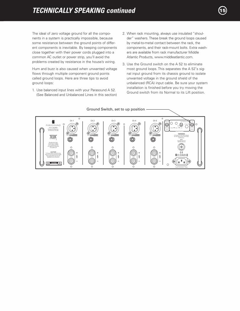
The ideal of zero voltage ground for all the compo-nents in a system is practically impossible, becausesome resistance between the ground points of differ-ent components is inevitable. By keeping componentsclose together with their power cords plugged into acommon AC outlet or power strip, you’ll avoid theproblems created by resistance in the house’s wiring.
Hum and buzz is also caused when unwanted voltageflows through multiple component ground pointscalled ground loops. Here are three tips to avoidground loops:
1. Use balanced input lines with your Parasound A 52.(See Balanced and Unbalanced Lines in this section)
2. When rack mounting, always use insulated “shoul-der” washers. These break the ground loops causedby metal-to-metal contact between the rack, thecomponents, and their rack-mount bolts. Extra wash-ers are available from rack manufacturer MiddleAtlantic Products, www.middleatlantic.com.
3. Use the Ground switch on the A 52 to eliminatemost ground loops. This separates the A 52’s sig-nal input ground from its chassis ground to isolateunwanted voltage in the ground shield of theunbalanced (RCA) input cable. Be sure your systeminstallation is finished before you try moving theGround switch from its Normal to its Lift position.
Ch 1 Ch 2 Ch 3 Ch 4 Ch 5
InputBalanced
UnbalancedInput
Balanced
UnbalancedInput
Balanced
UnbalancedInput
Balanced
UnbalancedInput
Balanced
Unbalanced
Man
Balanced
Inputs
Unbalanced Input 12 VOutput
Audio Sensitivity
50 mV 250
Ground
Normal
Lift
WARNINGTo Prevent Fire Or Shock Hazard,Do Not Expose This Unit To Rain
Or Moisture.
FuseT15A/250V1-115V AreaT8A/250V-230V Area
AC 115V 60HzAC 230V 50Hz
Power Consumption: 1350W
Parasound Products, Inc.San Francisco, CA USA
Manufactured underlicense from LucasfilmLtd. Lucasfilm and THX
are registered Trademarksof Lucasfilm Ltd.
CAUTIONTo Prevent Electric Shock, Do Not
Remove Cover. No User-ServiceableParts Inside, Refer Servicing To
Qualified Service Personnel.
Auto Turn On
L U C A S F I L ML M
Ground Switch, set to up position

PARASOUND A 52 DESIGN OVERVIEW16
Circuit Designed by John CurlParasound design consultant John Curl has been a legend among audiophiles and electronic engineers fordecades. He pioneered measurements to correlatemusical accuracy with the materials used in parts,worked with world-class touring companies, hasdesigned highly coveted audio classics, including the original Mark Levinson JC-2, Denneson JC-80,Vendetta Phono Preamplifier, and CTC Blowtorch preamplifiers; master recorders for Wilson Audio andMobile Fidelity; and the mixing consoles used in live concerts by The Grateful Dead and the MontreuxJazz Festival in Switzerland.
As our featured amplifier designer since 1990, he hascreated many products that have earned Parasoundworldwide acclaim. John is particularly proud of whathe and Parasound have accomplished together: “Thecircuits I design for Parasound are extremely sophisti-cated and are typical of products that are far moreexpensive. I can’t think of any other audio productsthat offer nearly as much bang for the buck.”
Parts SelectionEvery part within the A 52 is carefully chosen for itsaccuracy and reliability. Metal film resistors with 1%tolerance are selected for their precision and becausetheir values don’t drift as they heat up during opera-tion. Polypropylene and mica capacitors are usedextensively for their superior linearity and low dielec-tric absorption. Semiconductors are selected for superior performance in their specific roles in the circuit. Gold has the best conductivity of any metal,so we use high quality gold-plated input connectorsand speaker terminals. The double-sided circuit boardsare FR4 glass epoxy for long-term durability. The chassis is made of heavy gauge steel to safely housethe internal circuitry. This attention to detail whenselecting parts makes the difference between a verygood amplifier and an outstanding amplifier.
The Power SupplyThe heart of the power supply is a 1.4 kVA toroidalpower transformer, chosen for its efficiency, low hum field, and high power rating. Encapsulating thismassive power transformer in an epoxy-filled steelcanister assures ultra-quiet performance.
The A 52 power transformer employs multiple inde-pendent secondary windings so that each amplifierchannel has its own power supply, assuring more thanample DC voltage at all times and under all conditions.It also reduces inter-channel crosstalk that can blur the sound and impair the correct sense of whereinstruments, dialogue and effect are positioned.
Each channel’s +/- 60 Vdc B+ and B- supply rails usehigh-speed rectifier diodes and two large 10,000uF
electrolytic filter capacitors, chosen for their lowEquivalent Series Resistance (ESR) and dielectricabsorption. In addition, these filter capacitors arebypassed with smaller polypropylene capacitors toreduce AC ripple in the DC supply and to further eliminate noise and interference that is generated in AC power lines from computers and other appli-ances in the home.
Relay-Bypassed Soft Start CircuitWhen the A 52 is first turned on, there is a significantamount of in-rush current required to charge the enor-mous power supply capacitors. In order to suppressthis in-rush current and to prevent nuisance tripping of circuit breakers, we employ NTC (negative tempera-ture coefficient) resistors. These resistors cut the in-rush current by approximately 50%. Once they heatup, they essentially become a jumper with zero ohmsresistance. However, the A 52 goes one step further forthis circuit. After the NTC resistors have done their jobof suppressing in-rush current a gold contact relay auto-matically is activated to jump across the NTC resistorsto completely bypass them. This extra step insures thatthe resistors do not restrict any current whatsoever tothe power supply once the A 52 is in full operation.
Audio Circuit Path TopologyParasound’s circuit topology is a hybrid of carefullychosen discrete transistors that result in superior per-formance at each stage. We use JFETs (Junction FieldEffect Transistors) for the input stage; MOSFETs(Metal Oxide Field Effect Transistors) for the driverstage and bipolar transistors for the output stage.Discrete transistors are more sonically accurate thanintegrated circuits commonly used by other brands.
Complementary ConfigurationEach stage of amplification has transistors fed by thepositive DC power supply and complementary transis-tors fed by the negative DC power supply. Thus, halfof the devices amplify the positive half of the musicalwaveform while the other half of the devices amplifythe negative half. This complementary topology isinherently linear, which reduces distortion andimproves sonic accuracy.
The Input StageThe A 52’s input stage uses matched pairs of discreteJFETs arranged in a differential configuration. JFETsare ideal for the input stage because their inherentlyhigh impedance is unaffected by the impedance ofsource components. Differential configuration providessuperior noise reduction. These precision input JFETsare also cascoded to produce the current necessary to drive the MOSFET drivers in the following stage.

PARASOUND A 52 DESIGN OVERVIEW continued 17
The Driver StageThe driver stage provides critical amplification forwhich we employ a complementary matched pair ofMOSFETs selected for their tube-like sonic qualities.MOSFETs tend to generate less odd-order harmonicdistortion than bipolar transistors. This is importantbecause odd-order distortion sounds unnatural andfatiguing to the human ear, whereas even-order dis-tortion is less offensive because it is consonant,rather than dissonant. Our MOSFET driver stage pre-vents the harshness and brittle sound so often foundin other amplifiers.
The Output StageThe amplifier’s sonic characteristics are established byits input and driver stages. Now, the sole job of itsoutput stage is to deliver the enormous current andvoltage from its power supply to the speakers. Bipolaroutput transistors are better than MOSFETS in theoutput stage because of their higher safe operatingarea (SOA) and inherent ruggedness. Each channel’soutput stage employs two pairs of high current (15-ampere) bipolar transistors to insure long-term reliabil-ity, even with continuous high power operation andchallenging speaker loads. Lightning-fast (60 MHz)transistors respond instantly to complex demands inthe musical signal, virtually eliminating distortions thatoccur with slower transistors. Slew rate limiting andTransient Intermodulation Distortion (TIM) are simplynot an issue in the A 52.
Class A-A/B OperationPure class A operation provides the purest sound.However, an amplifier operating entirely in class Aoperation would be enormous, highly inefficient, andgenerate too much heat. Class A/B combines some ofthe advantages of Class A with the efficiency of ClassB operation. It is a compromise that reduces the heatgenerated in pure class A operation and the odd-orderharmonic distortion created in class B. In class AB,the driver and output stages are always partiallyturned on, which provides a nominal amount of pureclass A operation. At higher power levels, when themusical waveform swings from positive to negativeand vice versa, each bank of transistors is allowed to rest momentarily. This resting, or quiescent time,makes it possible to deliver high amounts of powerwithout overheating. It also makes it possible to usepassive cooling and avoid fans, whose noise can beheard over the music. The A 52 input and driverstages employ pure Class A while its output stageoperates with higher pure Class A power than manyamplifiers selling for twice or three times its price.The result is less fatiguing, more natural sound.
Total Protection - DC ServosDirect Current (DC) burns out speakers. Every poweramplifier must have some way to insure that DC fromits power supply never reaches its + or - speaker terminals. Most amplifiers simply use trim controls to reduce their DC offset or capacitors to block DC.Unfortunately, trim controls can allow DC offset toincrease over time, and even the most expensivecapacitors in the audio signal path will “veil” sonicclarity and attenuate bass response.
Parasound power amplifiers incorporate ingenious andfast-acting DC servo circuits, completely eliminatingthe need for coupling and blocking capacitors. The A 52 is direct-coupled from its input jacks to its speak-er terminals. This advanced circuitry never needsadjustment or maintenance. It operates outside theaudio signal path to keep the DC offset at the outputof the A 52 at a constant 0.00 Vdc. The results arestartling clarity, freedom from listening fatigue, andformidable bass response.
Total Protection - RelaysEach channel of the A 52 has a high-quality protectionrelay with gold-plated contacts for long-term reliability.These relays function to protect either the amplifier,the speakers, or both. When the A 52 is first poweredon, these relays remain open for three seconds as thepositive and negative power supplies stabilize andreach equilibrium. This prevents annoying popping orother transient noises. Relay protection also preventsdamage to your speakers in case of a catastrophicamplifier failure. Any amplifier that doesn’t use relayprotection for its speaker outputs compromises thesafety of the amplifier and your speakers.
Total Protection - Current Overload Specialized current-sensing transistors are connectedto the output stages of the A 52 to constantly monitorthe current flow through the output transistors. If thecurrent drawn by this stage exceeds a predeterminedsafe level due to a load impedance below 1 ohm or ashort circuit at the speaker terminals, the output relaywill open immediately to prevent any of the outputtransistors or other parts from failing.
Total Protection - FusesEach channel of the amplifier has a separate fuse forits positive and negative DC voltage rails. These fusesprovide backup protection in case the over-currentprotection does not work in time, or if an internal partfails. In the event of a part failure, these fuses haltoperation to minimize damage to additional parts.

PARASOUND A 52 SPECIFICATIONS18
Power Output - All Channels Driven125 watts RMS x 5, continuous,
20 Hz - 20 kHz, 8W
225 watts RMS x 5, continuous,
20 Hz - 20 kHz, 4W
Current Capacity30 amperes peak per channel
Slew Rate> 130 volts per microsecond
Frequency Response5 Hz - 100 kHz, +0/-3 dB at 1 watt
Total Harmonic Distortion< 0.2 % at full power
< 0.03 % at typical listening levels
IM Distortion< 0.04 %
TIMUnmeasureable
Dynamic Headroom> 1.5 dB
Interchannel Crosstalk> 78 dB at 1 kHz
> 63 dB at 20 kHz
Input ImpedanceUnbalanced: 47k W
Balanced: 94k W
Input Sensitivity for 28.28 V Output into 8 WUnbalanced: 1 V
Balanced: 1 V per leg
S/N Ratio> 113 dB, input shorted, IHF A-weighted
> 104 dB, input shorted, unweighted
Damping Factor> 1000 at 20 Hz
DC Trigger Requirements+9 Vdc to +12 Vdc, 2 mA
Audio Trigger Requirements50 mV AC - 250 mV AC
DC Trigger Output Capacity Requirements+12 Vdc, 150 mA
DimensionsWidth: 17 1⁄4" (437 mm)
Panel height: 5 1⁄4" (133 mm)
Height with feet: 5 7⁄8" (150 mm)
Depth: 19 3⁄4" (501 mm)
Power RequirementStandby: 25 Watts
Full Power into 8W : 1200 Watts
Net Weight50 1⁄4 lb. (22.8 kg)
Shipping Weight64 lb. (29 kg)
V 1.0 Features and specifications subject to change without notice. © Parasound Products, Inc. 2002.

Parasound Products, Inc. 950 Battery Street, San Francisco, CA 94111415-397-7100 / Fax 415-397-0144 www.parasound.com