A 3D nonlinear numerical analysis of buried steel pipes at ...
9
Građevinar 10/2016 815 GRAĐEVINAR 68 (2016) 10, 815-823 DOI: 10.14256/JCE.1317.2015 A 3D nonlinear numerical analysis of buried steel pipes at strike-slip fault crossings Primljen / Received: 8.4.2015. Ispravljen / Corrected: 16.1.2016. Prihvaćen / Accepted: 15.4.2016. Dostupno online / Available online: 10.11.2016. Authors: Professional paper Ercan Serif Kaya, Eren Uckan, Ferit Cakir, Bulent Akbas A 3D nonlinear numerical analysis of buried steel pipes at strike-slip fault crossings A 3D nonlinear soil-pipe interaction model is presented in this study to calculate the response of steel pipes subjected to strike-slip fault displacements. The general- purpose finite element analysis program ABAQUS is used to determine the seismic response of high strength steel pipes, as well as for various surrounding soil conditions and diameter to thickness, D/t, ratios. Relatively low strength pipes X65, and high strength pipes X70 and X80, which correspond to European pipes L450, L485 and L555, respectively, have been studied for various pipe diameters and thicknesses. Ključne riječi: buried steel pipes, fault crossings, pipelines, large-diameter pipes, transmitting systems Stručni rad Ercan Serif Kaya, Eren Uckan, Ferit Cakir, Bulent Akbas Prostorna nelinearna numerička analiza podzemnih čeličnih cjevovoda uslijed pomaka rasjeda U ovom se radu prikazuje trodimenzionalni nelinearni model interakcije između tla i cijevi, koji se koristi za proračun odziva čeličnih cijevi prilikom pomaka pružnih rasjeda. Za određivanje seizmičkog odziva čeličnih cijevi visoke čvrstoće i raznih uvjeta okolnog tla, te za proračun odnosa promjera i debljine, (D/t) korišten je računalni program ABAQUS. Cijev X65 koja se odlikuje relativno niskom čvrstoćom, te cijevi visoke čvrstoće tipa X70 i X80, koje odgovaraju cijevima L450, L485 i L555 prema europskoj klasifikaciji, analiziraju se za razne promjere i debljine cijevi. Ključne riječi: podzemne čelične cijevi, prijelazi preko rasjeda, cjevovodi, cijevi velikog promjera, transportni sustavi Fachbericht Ercan Serif Kaya, Eren Uckan, Ferit Cakir, Bulent Akbas Dreidimensionale numerische Analyse unterirdischer Stahlrohre an Blattverschiebungen In dieser Arbeit wird ein dreidimensionales nichtlineares Modell der Interaktion zwischen Boden und Rohr dargestellt, das für die Berechnung des Verhaltens von Stahlrohren bei Blattverschiebungen angewandt wird. Um die seismische Antwort von hochfesten Stahlrohren und durch die Umgebung enstehende Randbedingungen, sowie das Verhältnis von Durchmesser und Stärke D/t zu ermitteln, wird das Programm für Finite-Elemente-Analysen ABAQUS angewendet. Das Rohr X65, dem eine relativ kleine Festigkeit entspricht, sowie die Rohre X70 und X80, die gemäss europäischer Klassifikation den Typen L450, L485 und L555 entsprechen, werden für verschiedene Durchmesser und Rohrstärken analysiert. Ključne riječi: unterirdische Stahlrohre, Übergänge von Verwerfungen, Rohrleitungen, Rohre großen Durchmessers, Transportsysteme Assist.Prof. Ercan Serif Kaya, PhD. CE Alanya Alaaddin Keykubat University,Turkey Engineering Faculty, Department of Civil Engineering [email protected] Assoc.Prof.Eren Uckan, PhD. CE Bogazici University, Turkey Kandilli Observatory and Earthquake Research Institute (KOERI) [email protected] Assist.Prof. Ferit Cakir, PhD. CE Yildiz Technical University, Turkey University of California, Berkeley [email protected] Prof. Bulent Akbas, PhD. CE Gebze Technical University Department of Earthquake and Structural Engineering [email protected]
Transcript of A 3D nonlinear numerical analysis of buried steel pipes at ...

Građevinar 10/2016
815GRAĐEVINAR 68 (2016) 10, 815-823
DOI: 10.14256/JCE.1317.2015
A 3D nonlinear numerical analysis of buried steel pipes at strike-slip fault crossings
Primljen / Received: 8.4.2015.
Ispravljen / Corrected: 16.1.2016.
Prihvaćen / Accepted: 15.4.2016.
Dostupno online / Available online: 10.11.2016.
Authors:Professional paper
Ercan Serif Kaya, Eren Uckan, Ferit Cakir, Bulent Akbas
A 3D nonlinear numerical analysis of buried steel pipes at strike-slip fault crossings
A 3D nonlinear soil-pipe interaction model is presented in this study to calculate the response of steel pipes subjected to strike-slip fault displacements. The general-purpose finite element analysis program ABAQUS is used to determine the seismic response of high strength steel pipes, as well as for various surrounding soil conditions and diameter to thickness, D/t, ratios. Relatively low strength pipes X65, and high strength pipes X70 and X80, which correspond to European pipes L450, L485 and L555, respectively, have been studied for various pipe diameters and thicknesses.
Ključne riječi:buried steel pipes, fault crossings, pipelines, large-diameter pipes, transmitting systems
Stručni radErcan Serif Kaya, Eren Uckan, Ferit Cakir, Bulent Akbas
Prostorna nelinearna numerička analiza podzemnih čeličnih cjevovoda uslijed pomaka rasjeda
U ovom se radu prikazuje trodimenzionalni nelinearni model interakcije između tla i cijevi, koji se koristi za proračun odziva čeličnih cijevi prilikom pomaka pružnih rasjeda. Za određivanje seizmičkog odziva čeličnih cijevi visoke čvrstoće i raznih uvjeta okolnog tla, te za proračun odnosa promjera i debljine, (D/t) korišten je računalni program ABAQUS. Cijev X65 koja se odlikuje relativno niskom čvrstoćom, te cijevi visoke čvrstoće tipa X70 i X80, koje odgovaraju cijevima L450, L485 i L555 prema europskoj klasifikaciji, analiziraju se za razne promjere i debljine cijevi.
Ključne riječi:podzemne čelične cijevi, prijelazi preko rasjeda, cjevovodi, cijevi velikog promjera, transportni sustavi
FachberichtErcan Serif Kaya, Eren Uckan, Ferit Cakir, Bulent Akbas
Dreidimensionale numerische Analyse unterirdischer Stahlrohre an Blattverschiebungen
In dieser Arbeit wird ein dreidimensionales nichtlineares Modell der Interaktion zwischen Boden und Rohr dargestellt, das für die Berechnung des Verhaltens von Stahlrohren bei Blattverschiebungen angewandt wird. Um die seismische Antwort von hochfesten Stahlrohren und durch die Umgebung enstehende Randbedingungen, sowie das Verhältnis von Durchmesser und Stärke D/t zu ermitteln, wird das Programm für Finite-Elemente-Analysen ABAQUS angewendet. Das Rohr X65, dem eine relativ kleine Festigkeit entspricht, sowie die Rohre X70 und X80, die gemäss europäischer Klassifikation den Typen L450, L485 und L555 entsprechen, werden für verschiedene Durchmesser und Rohrstärken analysiert.
Ključne riječi:unterirdische Stahlrohre, Übergänge von Verwerfungen, Rohrleitungen, Rohre großen Durchmessers, Transportsysteme
Assist.Prof. Ercan Serif Kaya, PhD. CEAlanya Alaaddin Keykubat University,TurkeyEngineering Faculty, Department of Civil Engineering
Assoc.Prof.Eren Uckan, PhD. CEBogazici University, TurkeyKandilli Observatory and Earthquake Research Institute (KOERI)[email protected]
Assist.Prof. Ferit Cakir, PhD. CEYildiz Technical University, TurkeyUniversity of California, [email protected]
Prof. Bulent Akbas, PhD. CEGebze Technical UniversityDepartment of Earthquake and Structural Engineering

Građevinar 10/2016
816 GRAĐEVINAR 68 (2016) 10, 815-823
Ercan Serif Kaya, Eren Uckan, Ferit Cakir, Bulent Akbas
1. Introduction
Buried steel pipes are commonly used in oil and gas industry for transmitting hydrocarbon products from sources to end points. Critical hazards for such high quality pipelines are a) abrupt and b) spatially varying permanent ground deformations (PGD). Abrupt PGDs occur due to fault offsets. It is considered to be one of the most important extreme events for buried pipes as very large amounts of fault offsets need to be accommodated within a limited pipeline segment. As a result, axial strains in the pipe can attain very high values due to combined bending and axial deformation effects. Past earthquakes (1999 Kocaeli earthquake, Turkey; 1999 Chi-Chi earthquake, Taiwan) revealed the fact that the strain demand on pipes crossing active faults may be quite extreme due to relative movement of the fault with respect to the pipe axis [1]. When a continuous pipe is subjected to PGD due to fault rupture, the damage pattern depends on the type of the fault, material and geometric properties of the pipe. Pipes with high D/t ratios are usually more vulnerable than the pipes with low D/t ratios, where D and t are the diameter and thickness of the pipe, respectively [2, 3]. One of the best documented case studies of the buried continuous pipe response to fault offsets is possibly the Thames Water Pipeline during the 1999 Izmit (Turkey) event [4, 5]. A welded steel, D= 2.2 m water transmission pipe with (D/t = 122), crossing the Sapanca Segment of the North Anatolian Fault at an angle of β = 125 degrees in Kullar, south-eastern Izmit, Kocaeli, Turkey (Figure 1), was subjected to the right-side lateral fault ruptured with an offset of 2.45 m in Kullar, Izmit. The fault offset caused two major wrinklings and one minor buckling at three different locations along the pipe.The limit states for buried steel pipes are: a) maximum tensile strain, b) local buckling due to axial compressive strain (critical buckling
strain), c) distortion of pipeline cross sectiond) tearing of the pipe wall [2].
The amount of the strain depends on the type and orientation of the fault with respect to the pipe axis, geometric and material properties of the pipe (steel grade, pipe diameter and thickness), burial depth (deep or shallow), and the properties of the surrounding soil [2, 8]. A simplified model is commonly needed for engineering practice to determine the seismic demand of steel pipes at fault crossings [9]. A nonlinear analysis of the soil-pipe interaction system is needed for a detailed and accurate prediction of the mentioned seismic demand.In this study, a numerical analysis is carried out on a 3D nonlinear soil-pipe system using the finite element model that takes into account large strain and displacements. The response of the nonlinear pipe-soil interaction system to incrementally applied fault displacements (perpendicular to the pipe axis) is calculated.Deformations and distorted sections of the pipes are selected as the major response parameters along the critical length of the pipeline, Lcr, which is defined as the distance where the first plastic hinges occur on both sides of the fault line, and measured in the 3-D model as the S-shaped length of the deformed pipeline. The proposed model permits plastic hinge formation in the pipe due to incrementally applied fault movements, determines critical length of the pipeline, and measure strain developed at the tension and compression sides of the pipe. Minimum performance criteria for pipelines are proposed based on the analyses carried out in previous studies. Two performance levels are defined for pipelines: fully functional and partly functional.
2. Steel pipelines at fault crossings
The design of steel pipelines crossing a major fault line is based on the determination of axial strain. In general, two types of axial strains occur in the pipe [3]:a) Axial bending strain due to the transverse component of the
fault offset,b) Net axial deformations of the pipe due to the axial
(longitudinal) component of the fault offset.
The magnitude of pipe strain generally depends on the pipeline orientation with respect to the pipe axis, and on slip direction. A strike slip fault movement will induce an axial and transverse movements on steel pipes. The axial component will cause uniform axial strain in form of tension or compression. In the normal direction of the fault (90 degrees to the pipeline axis), the axial strain will be equal to zero, whereas the axial strain (tension/compression) will gradually increase with an increase in fault movement. As the fault movement increases, the tensile strain will develop due to pipe stretching in reverse direction. This will cause reduction in compressive strain after the peak compressive strain is reached [3]. The most significant deformation will happen in an effective length, L, of the S-shaped segment of the pipeline (Figure 2). L is defined as the distance where the first plastic hinges occur at both sides of the fault line, and L is measured as the S-shaped length of
Figure 1. A close-up view to the wrinkled pipe in Kullar, Izmit, during the 1999 Kocaeli Earthquake
Građevinar 10/2016
817GRAĐEVINAR 68 (2016) 10, 815-823
A 3D nonlinear numerical analysis of buried steel pipes at strike-slip fault crossings
the deformed pipeline in the 3D model, which is also equal to Lcr (Figure 2).The seismic design and analyses of steel pipes crossing fault lines are presented in detail in ALA [10] and ASCE [12] guidelines, and in Eurocode 8 [11]. The seismic evaluation of these pipes should rely on performance-based design principles, as proposed in this paper.
Figure 2. Critical length of the "S" shaped deformation of pipe (L)
3. Numerical analyses
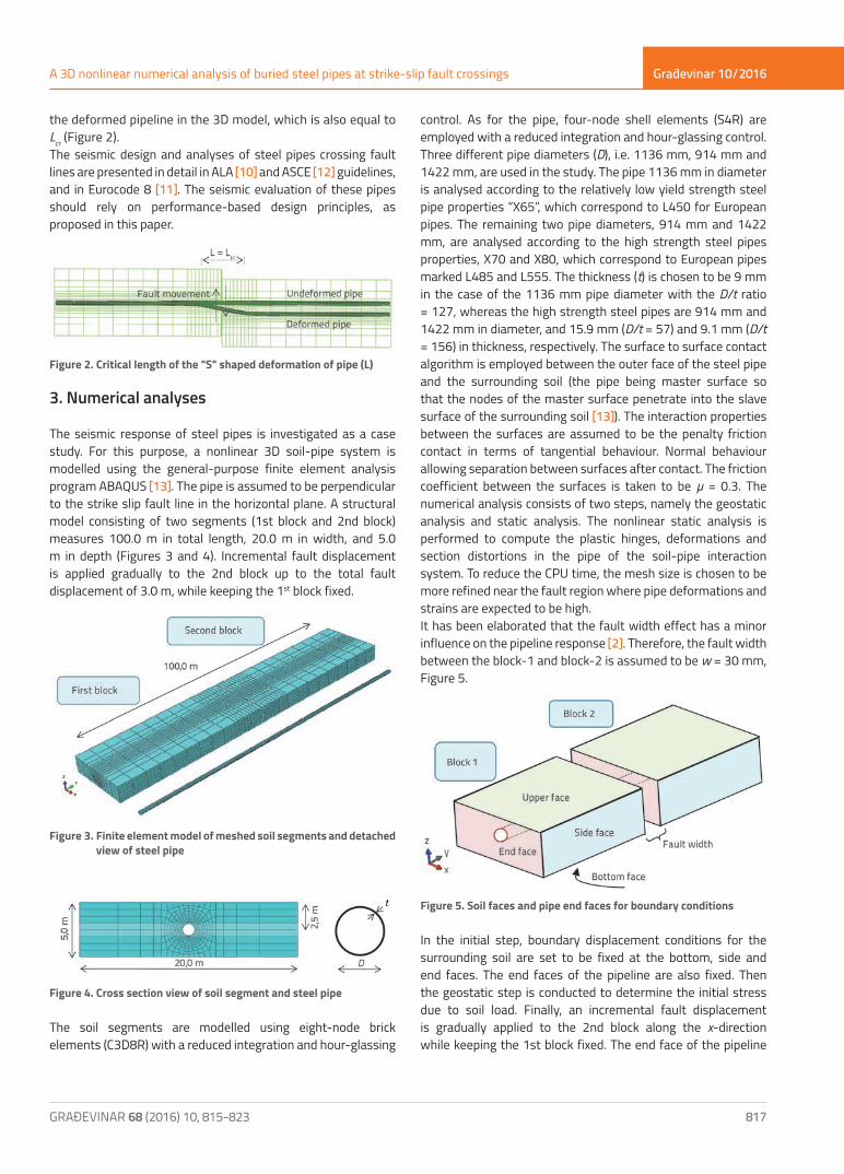
The seismic response of steel pipes is investigated as a case study. For this purpose, a nonlinear 3D soil-pipe system is modelled using the general-purpose finite element analysis program ABAQUS [13]. The pipe is assumed to be perpendicular to the strike slip fault line in the horizontal plane. A structural model consisting of two segments (1st block and 2nd block) measures 100.0 m in total length, 20.0 m in width, and 5.0 m in depth (Figures 3 and 4). Incremental fault displacement is applied gradually to the 2nd block up to the total fault displacement of 3.0 m, while keeping the 1st block fixed.
Figure 3. Finite element model of meshed soil segments and detached view of steel pipe
Figure 4. Cross section view of soil segment and steel pipe
The soil segments are modelled using eight-node brick elements (C3D8R) with a reduced integration and hour-glassing
control. As for the pipe, four-node shell elements (S4R) are employed with a reduced integration and hour-glassing control. Three different pipe diameters (D), i.e. 1136 mm, 914 mm and 1422 mm, are used in the study. The pipe 1136 mm in diameter is analysed according to the relatively low yield strength steel pipe properties “X65”, which correspond to L450 for European pipes. The remaining two pipe diameters, 914 mm and 1422 mm, are analysed according to the high strength steel pipes properties, X70 and X80, which correspond to European pipes marked L485 and L555. The thickness (t) is chosen to be 9 mm in the case of the 1136 mm pipe diameter with the D/t ratio = 127, whereas the high strength steel pipes are 914 mm and 1422 mm in diameter, and 15.9 mm (D/t = 57) and 9.1 mm (D/t = 156) in thickness, respectively. The surface to surface contact algorithm is employed between the outer face of the steel pipe and the surrounding soil (the pipe being master surface so that the nodes of the master surface penetrate into the slave surface of the surrounding soil [13]). The interaction properties between the surfaces are assumed to be the penalty friction contact in terms of tangential behaviour. Normal behaviour allowing separation between surfaces after contact. The friction coefficient between the surfaces is taken to be µ = 0.3. The numerical analysis consists of two steps, namely the geostatic analysis and static analysis. The nonlinear static analysis is performed to compute the plastic hinges, deformations and section distortions in the pipe of the soil-pipe interaction system. To reduce the CPU time, the mesh size is chosen to be more refined near the fault region where pipe deformations and strains are expected to be high.It has been elaborated that the fault width effect has a minor influence on the pipeline response [2]. Therefore, the fault width between the block-1 and block-2 is assumed to be w = 30 mm, Figure 5.
Figure 5. Soil faces and pipe end faces for boundary conditions
In the initial step, boundary displacement conditions for the surrounding soil are set to be fixed at the bottom, side and end faces. The end faces of the pipeline are also fixed. Then the geostatic step is conducted to determine the initial stress due to soil load. Finally, an incremental fault displacement is gradually applied to the 2nd block along the x-direction while keeping the 1st block fixed. The end face of the pipeline

Građevinar 10/2016
818 GRAĐEVINAR 68 (2016) 10, 815-823
Ercan Serif Kaya, Eren Uckan, Ferit Cakir, Bulent Akbas
at block 1 is set to be fixed, whereas it is released at block 2 along the x-direction to avoid excessive pipe stretching due to an increasing fault offset. It can be seen that the displacement controlled boundary condition at the end of pipe face, or at the connection between pipe end face and the soil block, may cause excessive strain due to pipe stretching effect. The pipe yields mainly under tension effect and resulting from actual strain values due to compression failure at the wrinkles, as long as soil block is subjected to lateral ground deformation.
4. Analysis of the results and discussion
The incremental fault displacement is gradually applied to the 2nd block up to the total fault displacement of 3.0 m, Figure 6. The following soil conditions are taken into account in this study: medium stiff clay and medium dense sand, with average stiff and soft clay soil parameters, and poorly and well graded sands. The clay cohesion is assumed to be c = 200 kPa, the Young’s modulus amounts to E = 50 MPa, the Poisson’s Ratio is
Figure 7. Pipe deformations, cross sectional distortions and axial strains of X65 pipe for sand conditions, D/t = 126 (pipe thickness t = 9 mm)
Figure 6. a) Soil and pipe interaction system after 3.0 m of fault displacement b) view cut
Građevinar 10/2016
819GRAĐEVINAR 68 (2016) 10, 815-823
A 3D nonlinear numerical analysis of buried steel pipes at strike-slip fault crossings
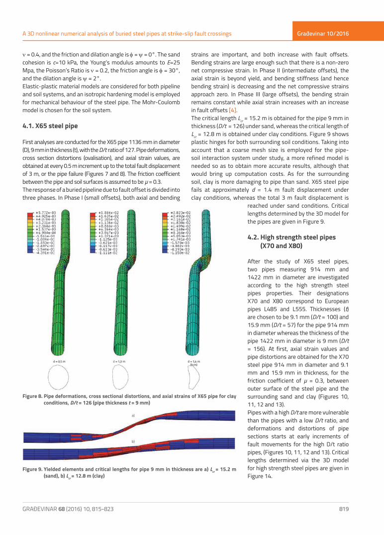
strains are important, and both increase with fault offsets. Bending strains are large enough such that there is a non-zero net compressive strain. In Phase II (intermediate offsets), the axial strain is beyond yield, and bending stiffness (and hence bending strain) is decreasing and the net compressive strains approach zero. In Phase III (large offsets), the bending strain remains constant while axial strain increases with an increase in fault offsets [4].The critical length Lcr = 15.2 m is obtained for the pipe 9 mm in thickness (D/t = 126) under sand, whereas the critical length of Lcr = 12.8 m is obtained under clay conditions. Figure 9 shows plastic hinges for both surrounding soil conditions. Taking into account that a coarse mesh size is employed for the pipe-soil interaction system under study, a more refined model is needed so as to obtain more accurate results, although that would bring up computation costs. As for the surrounding soil, clay is more damaging to pipe than sand. X65 steel pipe fails at approximately d = 1.4 m fault displacement under clay conditions, whereas the total 3 m fault displacement is
reached under sand conditions. Critical lengths determined by the 3D model for the pipes are given in Figure 9.
4.2. High strength steel pipes (X70 and X80)
After the study of X65 steel pipes, two pipes measuring 914 mm and 1422 mm in diameter are investigated according to the high strength steel pipes properties. Their designations X70 and X80 correspond to European pipes L485 and L555. Thicknesses (t) are chosen to be 9.1 mm (D/t = 100) and 15.9 mm (D/t = 57) for the pipe 914 mm in diameter whereas the thickness of the pipe 1422 mm in diameter is 9 mm (D/t = 156). At first, axial strain values and pipe distortions are obtained for the X70 steel pipe 914 mm in diameter and 9.1 mm and 15.9 mm in thickness, for the friction coefficient of µ = 0.3, between outer surface of the steel pipe and the surrounding sand and clay (Figures 10, 11, 12 and 13).Pipes with a high D/t are more vulnerable than the pipes with a low D/t ratio, and deformations and distortions of pipe sections starts at early increments of fault movements for the high D/t ratio pipes, (Figures 10, 11, 12 and 13). Critical lengths determined via the 3D model for high strength steel pipes are given in Figure 14.
Figure 9. Yielded elements and critical lengths for pipe 9 mm in thickness are a) Lcr = 15.2 m (sand), b) Lcr = 12.8 m (clay)
Figure 8. Pipe deformations, cross sectional distortions, and axial strains of X65 pipe for clay conditions, D/t = 126 (pipe thickness t = 9 mm)
ν = 0.4, and the friction and dilation angle is φ = ψ = 0°. The sand cohesion is c=10 kPa, the Young’s modulus amounts to E=25 Mpa, the Poisson’s Ratio is ν = 0.2, the friction angle is φ = 30°, and the dilation angle is ψ = 2°.Elastic-plastic material models are considered for both pipeline and soil systems, and an isotropic hardening model is employed for mechanical behaviour of the steel pipe. The Mohr-Coulomb model is chosen for the soil system.
4.1. X65 steel pipe
First analyses are conducted for the X65 pipe 1136 mm in diameter (D), 9 mm in thickness (t), with the D/t ratio of 127. Pipe deformations, cross section distortions (ovalisation), and axial strain values, are obtained at every 0.5 m increment up to the total fault displacement of 3 m, or the pipe failure (Figures 7 and 8). The friction coefficient between the pipe and soil surfaces is assumed to be µ = 0.3.The response of a buried pipeline due to fault offset is divided into three phases. In Phase I (small offsets), both axial and bending

Građevinar 10/2016
820 GRAĐEVINAR 68 (2016) 10, 815-823
Ercan Serif Kaya, Eren Uckan, Ferit Cakir, Bulent Akbas
Figure 11. Pipe deformations, cross sectional distortions and axial strains of X70 pipe for clay conditions, D/t = 100 (pipe thickness t = 9.1 mm), and friction coefficient is µ = 0.3
Figure 10. Pipe deformations, cross sectional distortions and axial strains of X70 pipe for sand conditions, D/t = 100 (pipe thickness t = 9.1 mm), and friction coefficient is µ = 0.3

Građevinar 10/2016
821GRAĐEVINAR 68 (2016) 10, 815-823
A 3D nonlinear numerical analysis of buried steel pipes at strike-slip fault crossings
Figure 12. Pipe deformations, cross sectional distortions and axial strains of X70 pipe for sand conditions, D/t = 57 (pipe thickness t = 15.9 mm), and friction coefficient is µ = 0.3
Figure 13. Pipe deformations, cross sectional distortions and axial strains of X70 pipe for clay conditions, D/t = 57 (pipe thickness t = 15.9 mm), and friction coefficient is µ = 0.3

Građevinar 10/2016
822 GRAĐEVINAR 68 (2016) 10, 815-823
Ercan Serif Kaya, Eren Uckan, Ferit Cakir, Bulent Akbas
Figure 16. Pipe deformations and axial strains values for the 3.0 m fault movement (X80 pipe, D = 914 mm, t = 15.9 mm, D/t = 57, µ = 0.3, clay)
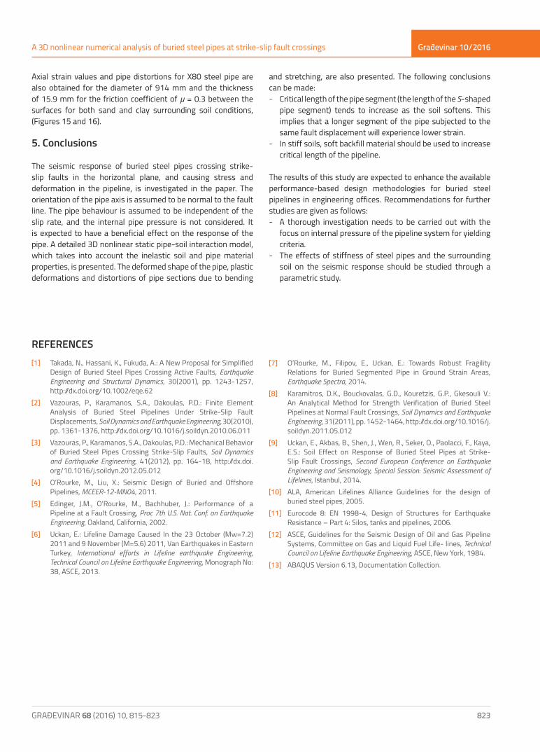
Figure 15. Pipe deformations and axial strains for various fault offset values ranging from 0.5 m to 3.0 m (X80 pipe, D = 914 mm, t = 15.9 mm, D/t = 57, µ = 0.3, sand)
Figure 14. Yielded elements and critical lengths for the pipe 914 mm in diameter are: a) Lcr = 10.4 m (t = 9 mm), and b) Lcr = 15.2 m (t = 15.9 mm) under clay conditions and µ = 0.3
Građevinar 10/2016
823GRAĐEVINAR 68 (2016) 10, 815-823
A 3D nonlinear numerical analysis of buried steel pipes at strike-slip fault crossings
Axial strain values and pipe distortions for X80 steel pipe are also obtained for the diameter of 914 mm and the thickness of 15.9 mm for the friction coefficient of µ = 0.3 between the surfaces for both sand and clay surrounding soil conditions, (Figures 15 and 16).
5. Conclusions
The seismic response of buried steel pipes crossing strike-slip faults in the horizontal plane, and causing stress and deformation in the pipeline, is investigated in the paper. The orientation of the pipe axis is assumed to be normal to the fault line. The pipe behaviour is assumed to be independent of the slip rate, and the internal pipe pressure is not considered. It is expected to have a beneficial effect on the response of the pipe. A detailed 3D nonlinear static pipe-soil interaction model, which takes into account the inelastic soil and pipe material properties, is presented. The deformed shape of the pipe, plastic deformations and distortions of pipe sections due to bending
and stretching, are also presented. The following conclusions can be made: - Critical length of the pipe segment (the length of the S-shaped
pipe segment) tends to increase as the soil softens. This implies that a longer segment of the pipe subjected to the same fault displacement will experience lower strain.
- In stiff soils, soft backfill material should be used to increase critical length of the pipeline.
The results of this study are expected to enhance the available performance-based design methodologies for buried steel pipelines in engineering offices. Recommendations for further studies are given as follows: - A thorough investigation needs to be carried out with the
focus on internal pressure of the pipeline system for yielding criteria.
- The effects of stiffness of steel pipes and the surrounding soil on the seismic response should be studied through a parametric study.
REFERENCES[1] Takada, N., Hassani, K., Fukuda, A.: A New Proposal for Simplified
Design of Buried Steel Pipes Crossing Active Faults, Earthquake Engineering and Structural Dynamics, 30(2001), pp. 1243-1257, http://dx.doi.org/10.1002/eqe.62
[2] Vazouras, P., Karamanos, S.A., Dakoulas, P.D.: Finite Element Analysis of Buried Steel Pipelines Under Strike-Slip Fault Displacements, Soil Dynamics and Earthquake Engineering, 30(2010), pp. 1361-1376, http://dx.doi.org/10.1016/j.soildyn.2010.06.011
[3] Vazouras, P., Karamanos, S.A., Dakoulas, P.D.: Mechanical Behavior of Buried Steel Pipes Crossing Strike-Slip Faults, Soil Dynamics and Earthquake Engineering, 41(2012), pp. 164-18, http://dx.doi.org/10.1016/j.soildyn.2012.05.012
[4] O’Rourke, M., Liu, X.: Seismic Design of Buried and Offshore Pipelines, MCEER-12-MN04, 2011.
[5] Edinger, J.M., O’Rourke, M., Bachhuber, J.: Performance of a Pipeline at a Fault Crossing, Proc 7th U.S. Nat. Conf. on Earthquake Engineering, Oakland, California, 2002.
[6] Uckan, E.: Lifeline Damage Caused In the 23 October (Mw=7.2) 2011 and 9 November (M=5.6) 2011, Van Earthquakes in Eastern Turkey, International efforts in Lifeline earthquake Engineering, Technical Council on Lifeline Earthquake Engineering, Monograph No: 38, ASCE, 2013.
[7] O’Rourke, M., Filipov, E., Uckan, E.: Towards Robust Fragility Relations for Buried Segmented Pipe in Ground Strain Areas, Earthquake Spectra, 2014.
[8] Karamitros, D.K., Bouckovalas, G.D., Kouretzis, G.P., Gkesouli V.: An Analytical Method for Strength Verification of Buried Steel Pipelines at Normal Fault Crossings, Soil Dynamics and Earthquake Engineering, 31(2011), pp. 1452-1464, http://dx.doi.org/10.1016/j.soildyn.2011.05.012
[9] Uckan, E., Akbas, B., Shen, J., Wen, R., Seker, O., Paolacci, F., Kaya, E.S.: Soil Effect on Response of Buried Steel Pipes at Strike-Slip Fault Crossings, Second European Conference on Earthquake Engineering and Seismology, Special Session: Seismic Assessment of Lifelines, Istanbul, 2014.
[10] ALA, American Lifelines Alliance Guidelines for the design of buried steel pipes, 2005.
[11] Eurocode 8: EN 1998-4, Design of Structures for Earthquake Resistance – Part 4: Silos, tanks and pipelines, 2006.
[12] ASCE, Guidelines for the Seismic Design of Oil and Gas Pipeline Systems, Committee on Gas and Liquid Fuel Life- lines, Technical Council on Lifeline Earthquake Engineering, ASCE, New York, 1984.
[13] ABAQUS Version 6.13, Documentation Collection.