A 0': ' (--)The Reactor Operations Annual Report presents a summary of reactor operating experience...
40
U Research Reactor Center University of Missouri-Columbia Research Park Columbia, MO 65211 PHONE (573) 88242 11 FAX (573) 882-6360 February 27, 2006 Document Control Desk U.S. Nuclear Regulatory Commission Mail Stop P1-37 Washington, DC 20555-0001 REFERENCE: SUBJECT: Docket 50-186 University of Missouri-Columbia Research Reactor Amended Facility License R-103 University of Missouri Research Reactor 2005 Reactor Operations Amnual Report I have enclosed one copy of the Reactor Operations Annual Report for the University of Missouri Research Reactor. The reporting period covers January 1, 2005 through December 31, 20C'5. This document is submitted to the U.S. Nuclear Regulatory Commission in accordance with the University of Missouri Research Reactor Technical Specification 6.1 .h (4). If you have any questions regarding the contents of this report, please contact me at (573) 882-5276. Sincerely, Les Foyto Reactor Manager Enclosure cc: Mr. Alexander Adams, U.S. NRC Mr. Craig Bassett, U.S. NRC -A 0': ' (--) AN EQUAL opPoRruNrrY/ADA INSTrruTON
Transcript of A 0': ' (--)The Reactor Operations Annual Report presents a summary of reactor operating experience...

U Research Reactor CenterUniversity of Missouri-Columbia
Research ParkColumbia, MO 65211
PHONE (573) 88242 11FAX (573) 882-6360
February 27, 2006
Document Control DeskU.S. Nuclear Regulatory CommissionMail Stop P1-37Washington, DC 20555-0001
REFERENCE:
SUBJECT:
Docket 50-186University of Missouri-Columbia Research ReactorAmended Facility License R-103
University of Missouri Research Reactor2005 Reactor Operations Amnual Report
I have enclosed one copy of the Reactor Operations Annual Report for the University of MissouriResearch Reactor. The reporting period covers January 1, 2005 through December 31, 20C'5.
This document is submitted to the U.S. Nuclear Regulatory Commission in accordance with theUniversity of Missouri Research Reactor Technical Specification 6.1 .h (4).
If you have any questions regarding the contents of this report, please contact me at (573) 882-5276.
Sincerely,
Les FoytoReactor Manager
Enclosure
cc: Mr. Alexander Adams, U.S. NRCMr. Craig Bassett, U.S. NRC
- A 0': �' (--)
AN EQUAL opPoRruNrrY/ADA INSTrruTON


UNIVERSITY OF MISSOURI
RE SEARCH REACTOR FACILITY
REACTOR OPERATIONSANNUAL REPORT
January 1, 2005 through December 31, 2005;
Compiled by the Research Reactor Staff
Submitted February 2006 by:
Leslie P. FoytoReactor AMlanager
Reviewed and Approved by:
Ralph A. Butler, PEDirector

UNIVERSITY OF MISSOURI - COLUMBIARESEARCH REACTOR
REACTOR OPERATIONS ANNUAL REPORT
January 1, 2005 through December 31, 2005
INTRODUCTION
The University of Missouri Research Reactor (MUJRR) is a multi-disciplinary research and educationfacility providing a broad range of analytical, materials science, and irradiation services to the researchcommunity and the commercial sector. Scientific programs include research in archaeometry,epidemiology, health physics, human and animal nutrition, nuclear medicine, radiation effects, radioisotope
studies, radiotherapy, and nuclear engineering; and research techniques including neutron activationanalysis, neutron and gamma-ray scattering, and neutron interferometry. The heart of this facility is apressurized, reflected, open pool-type, light water moderated and cooled, heterogenous reactor designed foroperation at a maximum steady state power level of 10 Megawatts thermal - the highest powered
University-owned research reactor in the world.
The Reactor Operations Annual Report presents a summary of reactor operating experience for calendar
year 2005. Included within this report are changes to MURR procedures, revisions to the HazardsSummary Report, facility modifications, new tests and experiments, reactor physics activities, andenvironmental and health physics data.
This Report is being submitted to the U.S. Nuclear Regulatory Commission to meet the administrative
requirements of MURR Technical Specification 6.1 .Lh (4).
ACKNOWLEDGMENTS
The success of MURR and these scientific programs is due to the dedication and hard work of manyindividuals and organizations. Included within this group are: the University administration; the governing
officials of the State of Missouri; the Missouri State Police; the City of Columbia Police Department; theMissouri University Police Department; our Regulators; those who have provided funding including theDepartment of Energy (DOE) and the Department of Homeland Security; the Researchers; the Students; the
Columbia Fire Department; the Campus Facilities organization; members of the National Organization ofTest, Research, and Training Reactors; and many others who have made, and will continue to make, keycontributions to our overall success. To these individuals and organizations, the staff of MURR wishes to
extend its fondest appreciation.
In addition to the items discussed in this Report, a considerable amount of time and resources were directedthis year towards the beryllium reflector replacement, and renewal and relicensing projects. Replacementof the beryllium reflector is performed every eight years, with the next replacement scheduled for January
2006. Including low power physics testing, approximately seven to eight days is required to disassemblethe necessary piping and equipment, remove the old beryllium and insert the new, and then reassembly ofall piping and equipment. Planning for this evolution takes approximately one year, including training,procedure writing, and the procurement of all spare parts and tools, and involves nearly every group within
the facility. Additionally, in conjunction with the beryllium replacement, three beamtubes will be retracted
in order to replace four graphite reflector elements.
i

The facility's operating license, R-103, is due to expire on October 11, 2006. Efforts to revise and update
the Safety Analysis Report for relicensing submittal are ongoing, with a considerable amount of energyfocused on the necessary computer codes to support the nucleonics and accident analyses chapters.
Renewal projects are also ongoing, with the completion of two major projects this year: cooling towerelectrical and radioactive liquid waste disposal system upgrades.
Reactor Operations Management also wishes to commend the three individuals who received their Reactor
Operator certifications from the U.S. Nuclear Regulatory Commission. These individuals participated in arigorous training program of classroom seminars, self-study, and on-the-job training. The results of thistraining are confident, well-versed, decisive individuals capable of performing the duties of licensed
operators during normal and abnormal situations.
1ii
TABLE OF CONTENTS
Section Title Pages
1. Reactor Operations Summary ........................................ I-1 through 10
II. MURR Procedures ......................................... II-l through 9
A. Changes to Reactor Operations Procedures
B. Changes to the MURR Site Emergency Proceduresand Facility Emergency Procedures
C. Changes to Health Physics Procedures,Byproduct Material Shipping Procedures, andPreparation of Byproduct Material for Shipping Procedures
III. Revisions to the Hazards Summary Report .......................................... III-1 through 2
IV. Plant and System Modifications .......................................... IV- 1 through 3
V. New Tests and Experiments ............ ............................ V-1
VI. Special Nuclear Material and Reactor Physics Activities ..................... VI-l
VII. Radioactive Effluent ........................................ VII- 1 through 2
Table 1 - Sanitary Sewer Effluent
Table 2 - Stack Effluent
VIII. Environmental Monitoring and Health Physics Surveys ...................... VIII- I through 5
Table 1 - Summary of Environmental Set 67
Table 2 - Summary of Environmental Set 68
Table 3 - Environmental TLD Summary
Table 4 - Number of Facility Radiation and Contamination Surveys
IX. Summary of Radiation Exposures to Facility Staff, Experimenters,and Visitors . IX-I
SECTION I
REACTOR OPERATIONS SUMMARY
January 1,2005 through December 31, 2005
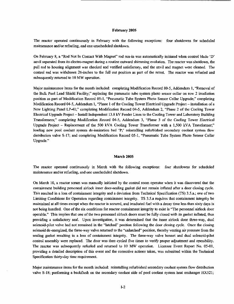
The following table and discussion summarize reactor operations during the period from January 1, 2005 throughDecember 31, 2005.
Full Power % of Full Power % ofIMont Full Power Hours Megawatt Days Total Time Scheduled*
January 670.48 279.46 90.12 100.90February 604.64 252.04 89.98 100.77March 662.67 276.20 89.07 99.72April 547.65 228.34 76.06 85.30May 673.75 280.87 90.56 101.39June 670.17 279.33 93.08 104.39July 681.09 283.90 91.54 102.50
August 669.82 279.19 90.03 100.80September 639.11 266.67 88.76 99.55October 626.76 261.32 84.24 94.32
November 631.52 263.28 87.71 98.37December 683.72 285.07 91.90 102.89Total for 7761.38 3235.67 88.60 % 99.21 %th e _Y ear _ _ _ _ _ _ _ _ _ _ _ _ _ _ _ _ _ _ _ _ _ _ _ _ _ _ _ _ _ _
*MURR is scheduled to average at least 150 hours of full power operation per week. Total time is the number ofhours in the month listed or the year.
January 2005
The reactor operated continuously in January with the following exceptions:maintenance and/or refueling. There were no unscheduled shutdowns this month.
five shutdowns for scheduled
Major maintenance items for the month included: replacing the shaft keeper key on cooling tower fan CTF-3 motorcoupling; completing Compliance Procedure No. 31, "Calibration of the Eberline Radiation Stack Monitor;"adjusting the operating linkage on pool coolant system heat exchanger bypass valve S-2; replacing the filtercartridges in pool coolant demineralizer system inlet filter housing F-200; cleaning the suction strainer for secondarycoolant system pump SP-3; replacing the flange gaskets, studs, and nuts, and valve diaphragms for primary coolantdemineralizer system inlet filter housing F-201; and replacing the high pressure isolation valve for primary coolantsystem heat exchanger differential pressure transmitter DE'S-928B.
]:-1
February 2005
The reactor operated continuously in February with the following exceptions: four shutdowns for scheduledmaintenance and/or refueling, and one unscheduled shutdown.
On February 8, a "Rod Not In Contact With Magnet" rod run-in was automatically initiated when control blade 'D'anvil separated from its electromagnet during a routine outward shimming evolution. The reactor was shutdown, thepull rod to housing alignment was checked and verified satisfactory, and the anvil and magnet were cleaned. Thecontrol rod was withdrawn 26-inches to the full out position as part of the retest. The reactor was refueled andsubsequently returned to 10 MW operation.
Major maintenance items for the month included: completing Modification Record 80-5, Addendum 1, "Removal ofthe Bulk Pool Lead Shield Facility;" replacing the pneumatic tube system photo sensor collar on row 2 irradiationposition as part of Modification Record 05-1, "Pneumatic Tube System Photo Sensor Collar Upgrade;" completingModification Record 04-5, Addendum 1, "Phase 1 of the Cooling Tower Electrical Upgrade Project - Installation of aNew Lighting Panel LP-41;" completing Modification Record 04-5, Addendum 2, "Phase 2 of the Cooling TowerElectrical Upgrade Project - Install Independent 13.8 kV Feeder Lines to the Cooling Tower and Laboratory BuildingTransformers;" completing Modification Record 04-5, Addendum 3, "Phase 3 of the Cooling Tower ElectricalUpgrade Project - Replacement of the 500 kVA Cooling Tower Transformer with a 1,500 kVA Transformer;"loading new pool coolant system de-ionization bed 'P;' reinstalling refurbished secondary coolant system flowdistribution valve S-17; and completing Modification Record 05-1, "Pneumatic Tube System Photo Sensor CollarUpgrade."
March 2005
The reactor operated continuously in March with the following exceptions: four shutdowns for scheduledmaintenance and/or refueling, and one unscheduled shutdown.
On March 10, a reactor scram was manually initiated by the control room operator when it was discovered that thecontainment building personnel airlock inner door-sealing gasket did not remain inflated after a door closing cycle.This resulted in a loss of containment integrity and a deviation from Technical Specification (TS) 3.5.a.; one of twoLimiting Conditions for Operation regarding containment integrity. TS 3.5.a requires that containment integrity bemaintained at all times except when the reactor is secured, and irradiated fuel with a decay time less than sixty days isnot being handled. One of the six conditions for reactor containment integrity to exist is "The personnel airlock dooroperable." This implies that one of the two personnel airlock doors must be fully closed with its gasket inflated, thusproviding a satisfactory seal. Upon investigation, it was determined that the inner airlock door three-way, dualsolenoid-pilot valve had not remained in the "latched" position following the door closing cycle. Once the closingsolenoid de-energized, the three-way valve returned to the "unlatched" position, thereby venting air pressure from thesealing gasket resulting in a loss of containment integrity. The three-way valve bonnet and dual solenoid-pilotcontrol assembly were replaced. The door was then cycled five times to verify proper adjustment and operability.The reactor was subsequently refueled and returned to 10 MW operation. Licensee Event Report No. 05-01,providing a detailed description of this event and the corrective actions taken, was submitted within the TechnicalSpecification thirty-day time requirement.
Major maintenance items for the month included: reinstalling refurbished secondary coolant system flow distributionvalve S-18; performing a backflush on the secondary coolant side of pool coolant system heat exchanger HX521;
1-2
replacing the drive motor for the containment building personnel airlock outer door; reinstalling refurbished
secondary coolant system flow distribution valve S-19; and completing Compliance Procedure No. 29, "Calibrationof the NMC RAK Radiation Stack Monitor."
April 2005
The reactor operated continuously in April with the following exceptions: three shutdowns for scheduled
maintenance and/or refueling, and three unscheduled shutdowns. NRC regional inspector arrived at MURR for
routine inspection.
On April 5 during a normal reactor startup, a "Nuclear Instrumentation Channel No. 4 High Power" rod run-in was
automatically initiated while proceeding from 5 to 10 /.Ws. The set point for the rod run-in is 114%, while thehighest power attained was 110% - as indicated by Channel No. 4 chart recorder and the remote meter on the controlconsole. All other Nuclear Instrumentation (NI) channel indications were normal. Troubleshooting revealed a
mismatch between the remote indicators (chart recorder and console meter) and the linear bar graph display on the NI
drawer. Calibration of the linear bar graph was verified in specification. The isolator module, which amplifies andisolates the drawer output signal for use by the remote indicators, was replaced and calibration between the linear bargraph and the remote indicators was verified satisfactory. Trip settings were then verified after replacement and thenconfirmed again during "Front Panel Checks" prior to startup. The reactor was subsequently restarted to 10 MW
operation. NOTE: Trip settings are set based on drawer calibrated indication, not remote indication. No deviation
from Technical Specification Limiting Conditions of Operation for high power rod run-in or reactor scram occurred.
On April 8, a "Nuclear Instrumentation Channel No. 4 High Power" rod run-in was automatically initiated while
adjusting Signal Processor drawer No. 1 gain potentiometer to increase console remote meter indication to greaterthan 100%. This is a routine adjustment at power that is necessary to maintain Nuclear Instrumentation (NI)indications within the administrative operating range of 100 to 105%, after first verifying power by manual heat
balance. At the start of the adjustment, remote meter indication was reading approximately 98.5% with a gainpotentiometer setting of 369. A Senior Reactor Operator had increased the setting to 427, which caused consolemeter indication to increase to approximately 99.5% when the rod run-in occurred. Console meter indication wasobserved by two operators. Chart recorder indication was approximately 114%, the value of the rod run-in set point.Drawer indication was not known, as this indication is not typically viewed during adjustment. However, comparisonof local and remote indications is verified prior to startup. All other NI channel indications were normal, thusindicating that no actual reactivity transient occurred. Troubleshooting efforts did not reveal any discrepancies. TheNI drawer was removed and a spare drawer was installed and calibrated. The reactor was subsequently refueled andreturned to 10 MW operation. The removed NI drawer will undergo further bench top troubleshooting. NOTE: A
potentiometer adjustment of 100 correlates to a percent power indication change of approximately 3%. In this case,an increase in the setting of 58 would be expected to increase meter indication approximately 1 to -/2 °/0, as it did.
On April 22, a reactor scram was manually initiated by the control room operator when facility fire main pressuredecreased and remained below the minimum pressure required for emergency pool fill availability. Uponinvestigation, the University water supply line immediately outside the facility grounds had ruptured, causing a low-
pressure condition. Campus Energy Management isolated and repaired the leak. The reactor was subsequentlyrefueled and returned to 10 MW operation.
Major maintenance items for the month included: placing an epoxy patch on the secondary coolant side of primary
heat exchanger HX503A; completing Modification Record 95-3, Addendum 1, "Redesign and Replacement of the
1-3
GH Reflector Wedge;" replacing a section of emergency pool fill piping which enters the containment structure
through the utility seal trench; performing a backflush on the secondary coolant side of pool coolant system heat
exchanger HX521; completing the biannual cleaning of the cooling tower sump and basin; and completing the
biennial changeout of control blade 'A' offset mechanism.
May 2005
The reactor operated continuously in May with the following exceptions: five shutdowns for scheduled maintenance
and/or refueling, and two unscheduled shutdowns.
On May 9 during a normal reactor startup, a "Rod Not in Contact with Magnet" rod run-in was automatically initiated
when control blade 'A' separated from its electromagnet while performing a shimming evolution. Initial
troubleshooting efforts revealed no abnormalities. Compliance Procedure No. 10 was performed, which verified
satisfactory alignment for the control blade's full travel (26-inches), and the reactor was eventually restarted to 10
MW operation. During the following scheduled maintenance day it was discovered that the allen head screw, which
attaches the magnet to the drive tube, was installed backwards. The drive tube is a hollow aluminum tube that is
tapped on one side and has a non-threaded hole on the other side. The screw was attached to the drive tube first
through the threaded side, which allowed more "slop" between the magnet and drive tube. Additionally, the magnetcabling was pulled too tight through its securing clamp, thus not allowing sufficient freedom for the magnet to hang.
Both of these conditions caused the magnet to tilt approximately 20 degrees off vertical centerline. With the magnetnot hanging freely and vertically, it had a tendency to push the anvil to one side as it engaged, thus causing the anvil
to drag against the housing and the magnet to pull off. The remaining control blade magnets were also checked to
ensure that they hung freely and vertically.
On May 18, the control Rod Position Indication (RPI) system remote Operator Display Assembly (ODA) display
screen on the control console failed (went blank). The master local display chassis on the Instrument Panel remained
operational; therefore RPI was still available to the operators. After conferring with the Reactor Manager, the Lead
Senior Reactor Operator shutdown the reactor to troubleshoot the ODA. The Chief Electronic Technician determined
that the ODA display control card had failed. The spare display control card was installed which returned the ODA
to operation. The reactor was subsequently refueled and returned to 10 MW operation.
Major maintenance items for the month included: replacing Nuclear Instrumentation Signal Processor No. 2 drawer;
replacing the batteries for the Uninterruptible Power Supply; completing Compliance Procedure No. 26,
"Containment Building Compliance Test;" and completing Modification Record 95-1, Addendum ID, "Replace
Existing Gamma-Metrics High Voltage Plasma Bargraphs with Liquid Crystal Displays."
June 2005
The reactor operated continuously in June with the following exceptions: four shutdowns for scheduled maintenanceand/or refueling. There were no unscheduled shutdowns this month.
On June 6 during a normally scheduled reactor shutdown, it was discovered that the head pin, which secures the hold-
down rod assembly, had been improperly installed on the three-tube flux trap sample holder during the previousreactor shutdown on May 30. Failure to have the head pin properly installed resulted in a deviation from TechnicalSpecification (TS) 3.6.e; one of fifteen (15) Limiting Conditions for Operation regarding experiments. TS 3.6.e
14

states, "Only movable experiments in the center test hole shall be removed or installed with the reactor operating. Allother experiments in the center test hole shall be removed or installed only with the reactor shut dovm. Securedexperiments shall be rigidly held in place during reactor operation." Additionally, TS definition 1.24 for a securedexperiment states "A secured experiment is any experiment which is rigidly held in place by mechanical. means with
sufficient restraint to withstand any anticipated forces to which the experiment might be subjected." Failure to havethe head pin properly installed resulted in a component of a secured experiment, which was installed in the center testhole, not being rigidly held in place during reactor operation.
It should be noted that the flux trap sample holder itself was at all times rigidly held in place while inserted into thereactor. As described in the safety analysis section of the Licensee Event Report, the reactivity worth of the sampleholder is approximately 75% of the total reactivity worth of the experiment. The reactivity worth of all of thesamples and spacers in the holder was only 0.00114 AK - slightly greater than the TS limit for a movable experiment.
The reactivity that could have been introduced by movement of these samples and spacers in all three tubes was only0.00037 AK, less than the limit for a movable experiment. Furthermore, any potential movement of samples or
spacers was confined within the sample holder. Therefore, no reactor safety hazard existed with the flux. trap sampleholder pin improperly installed during reactor operation. Licensee Event Report No. 05-02, providing a detaileddescription of this event and the corrective actions taken, was submitted within the Technical Specification thirty-day
time requirement.
Major maintenance items for the month included: replacing the roots blower on the NMC RAK radiation stack
monitor; performing a zero and span, and calibration on the pool coolant system flow transmitter FT-912D;performing a backflush on the secondary coolant side of pool coolant system heat exchanger HX521; replacing therod run-in system trip actuator amplifier; replacing the secondary coolant system pH probe; completing ComplianceProcedure No. 31, "Calibration of the Eberline Radiation Stack Monitor;" and replacing a fuse on the display controlcard for the Rod Position Indication system remote Operator Display Assembly.
July 2005
The reactor operated continuously in July with the following exceptions: four shutdowns for scheduled maintenance
and/or refueling, and one unscheduled shutdown (power reduction).
On July 8, a "Nuclear Instrumentation Channel No. 5 High Power" rod run-in was automatically initiated when amovable sample was being removed from the graphite reflector region during a routine sample handling evolution.While pulling the sample holder out, its handling cable became entangled with an adjacent sample's cables, causingboth sample holders to be withdrawn from the reflector region at the same time. The reactivity insertion caused bythe removal of both samples automatically initiated the rod run-in. The rod run-in was reset, and the reactor wasreturned to 10 MW operation. The operators involved were counseled on the importance of ensuring only one sampleis pulled from the reflector region at a time. Note: The combined reactivity effect due to the removal of both sampleholders simultaneously did not exceed the Technical Specification limit of 0.001 AK for a movable experiment.
Major maintenance items for the month included: replacing the power supply for the Rod Position Indication systemremote Operator Display Assembly; loading new pool coolant system de-ionization bed 'B;' replacing the aircompressor for the facility instrument air system; replacing Nuclear Instrumentation Intermediate Range Channel No.
2 remote meter face; completing Modification Record 04-5, Addendum 4, "Phase 4 of the Cooling Tower ElectricalUpgrade Project - Replacement of Substation 'A' and the Motor Control Centers;" completing Modification Record04-5, Addendum 6, "Phase 6 of the Cooling Tower Electrical Upgrade Project - Replacement of the 15 kVA
I-5

Transformer with a 45 kVA Transformer;" and replacing the bypass piping for the secondary coolant system auto
make-up water valve.
August 2005
The reactor operated continuously in August with the following exceptions: five shutdowns for scheduledmaintenance and/or refueling, and one unscheduled shutdown.
On August 22 during a normal reactor startup, a "Nuclear Instrumentation Channel No. 3 Short Period" rod run-in
was automatically initiated when an "Anti-Siphon Tank HI-LO Pressure" annunciator alarm occurred. The controlrods had been withdrawn to a height of approximately two inches from the fully inserted position when the rod run-in
occurred. Anti-Siphon System pressure had lowered to the alarm set point as a result of system cool-down prior to
startup. The rod run-in was most likely caused by electrical "noise" from the annunciator alarm because the pressureswitch is located immediately adjacent to the nuclear instrumentation detector. A reactor startup was subsequently
performed to 10 MW operation.
Major maintenance items for the month included: replacing the logic relay in the building exhaust ventilation systemfan failure circuit; transferring the old beryllium reflector and tantalum wedge from the reactor pool to a storage cask;completing Modification Record 05-3, "Electrical Distribution Modifications Associated with the New Chill WaterLoop;" and installing a rebuilt cooling fan in the Instrument Panel.
September 2005
The reactor operated continuously in September with the following exceptions: three shutdowns for scheduled
maintenance and/or refueling, and five unscheduled shutdowns.
Four (4) reactor loop low flow scrams occurred within a three-day period while operating at 10 MW. The followingindications were common to each occurrence:
1. No indications of an actual reduction in primary coolant flow was recorded on the chart recorder;
2. No reactor loop low flow alarm was received; and
3. All lights on the "Yellow Leg" and only lights I and 2 remained lit on the "Green Leg" of the reactorscram monitoring system ("White Rat"), thus indicating that the most likely cause was the "B" loop of
the primary coolant system - flow transmitter FT-912E Instrumentation String.
First Shutdown at 15:32, September 3: Suspected air bubbles in the sensing lines of flow transmitter FT-912E as the
most probable cause. Transmitter high and low-pressure sides were vented and Compliance Procedure No. 4B wasperformed to verify scram set point and transmitter calibration - both were within specification. Permission to restart
the reactor was obtained from the Reactor Manager.
Second Shutdown at 21:59, September 3: Because the above stated indications would imply that there was no actualdrop in current, or signal, within the instrument loop (i.e., no corresponding low flow alarm), troubleshooting effortswere directed at components that could intermittently fail and provide only a reactor scram and annunciation: dual
alarm unit EP-920C/D, scram relay K-38, and any interconnect wiring. After systematically eliminating K-38 andany interconnect wiring as the probable cause, focus was placed on the dual alarm unit. The dual alarm unit was
replaced with one from spare parts. Compliance Procedure No. 4B and 7A were performed to verify scram set point
1-6

settings were satisfactory. Additionally, a multi-meter was connected to the chart recorder test points to continuouslymonitor the instrumentation current loop. The multi-meter was selected to the MIN function, which would record thelowest current reading during a transient. Permission to restart the reactor was obtained from the Reactor Manager.
Third Shutdown at 08:15, September 4: The multi-meter did not record any decrease in current that would havecaused a reactor scram - lowest current reading correlated to a flow rate of 1880 gpm; well above the scram set point
of 1725 gpm. Interconnected wiring was rechecked. Replaced primary coolant "B" loop flow scram relay K-38 andonce again replaced dual alarm unit EP-920C/D with one from spare parts. Compliance Procedure Nc. 4B and 7Awere performed to verify scram set point settings were satisfactory. In addition to the multi-meter thai was already
connected to the chart recorder, a second multi-meter was connected to the dual alarm unit to monitor its +24Voutput. The multi-meter was selected to the MIN function, which would record the lowest voltage reading during a
transient. By the use of the two multi-meters and the installed "White Rat," all instrumentation output signals withinthe FT-912E Instrumentation String were monitored. Permission to restart the reactor was obtained from the Reactor
Manager.
Fourth Shutdown at 03:12, September 5: This shutdown occurred while performing Compliance Procedure No. 10,"Control Rod Drop Times," during the normally scheduled Monday morning shutdown. All indications provided by
the multi-meters were normal, suggesting that no actual trip signal was generated by either the flow transmitter or thedual alarm unit. Troubleshooting efforts were again focused at the interconnect wiring between the output of the dualalarm unit and relay K-38. A more rigorous investigation of the interconnect wiring and connection points was
performed including the disassembly and inspection of the "Green Leg" connector and K relay drawer. Thisinspection once again yielded no definitive cause. After exhausting all known options and testing, the dual alarmunits for the "Green" and "Yellow Legs," EP-920C/D and EP-920A/B respectively, were swapped. If anothershutdown would have occurred, this would have provided us additional troubleshooting information depending onwhether the scram was generated in the "Yellow" or "Green Leg." Compliance Procedure No. 4A/B and 7A/B wereperformed to verify scram set point settings were satisfactory. Permission to startup the reactor was obtained fromthe Reactor Manager following completion of the normal maintenance day activities.
No further reactor loop low flow scrams have been received. Although no definitive cause could be found, nor could
a duplication of the event be created during troubleshooting activities, the most probable cause was a loose connectorthat was not apparent when disconnected.
On September 13, a "Reactor Loop Low Flow" scram was automatically initiated when primary coolant system pumpP-501B breaker opened while operating. The motor phase currents and resistance to ground were measured with allreadings indicating nothing unusual. Both motor and pump were checked for free rotation. Additionally, vibrationanalysis of the motor/pump did not indicate any abnormalities. No definitive cause could be identified. Anelectronic data logger was connected to all three phases of the motor to record run current in the event of a similaroccurrence. The primary coolant system was operated for approximately 30 minutes with no abnormal indications.The reactor was refueled and subsequently returned to 10 MW operation.
Major maintenance items for the month included: replacing the reactor safety system dual alarm unit EP-920C/D;replacing the primary coolant 'B' loop low flow scram relay K-38; replacing the pool coolant 'B' loop low flowscram relay K-37; replacing the sensing line piping on the high-pressure side of pool coolant system flow transmitterFT-912F; and replacing the primary coolant system temperature element TE-980B meter relay unit.
1-7
October 2005
The reactor operated continuously in October with the following exceptions: six shutdowns for scheduled
maintenance and/or refueling, and one unscheduled shutdown. NRC regional inspector arrived at MURR for routineinspection. Three reactor startups were performed for NRC operator licensing examinations.
On October 6, a "Reflector HI-LOW Differential Pressure" scram was automatically initiated when a 3-inch sample
holder was removed from the reactor pool reflector region during a normal sample handling evolution. Removal of
the sample holder, combined with a lower than normal pool coolant flow, created a low differential pressurecondition across the reflector region. Pool coolant flow had gradually decreased over the 12 hours prior to the
shutdown for no apparent reason. During troubleshooting efforts, the pool coolant and pool coolant demineralizer
system filters were removed and inspected. Fibrous material, similar to that of nylon rope, was found on the filters.
The filters were either replaced or cleaned, as applicable, and pool coolant system flows returned to normal. The
most probable scenario is that a section of nylon rope, which is used to hang off items in the pool, had come loose
and entered the pool coolant loop through natural convection valve 547. This valve is located near the pool bottom
and is maintained open during operation. Once in the loop, the combination of gamma radiation and the pool
coolants pumps had deteriorated the rope to point where it had disintegrated and collected on the filters. The reactorwas refueled and subsequently returned to 10 MW operation.
Major maintenance items for the month included: completing Compliance Procedure No. 29, "Calibration of theNMC RAK Radiation Stack Monitor;" replacing the filter cartridges in pool coolant demineralizer system inlet filter
housing F-200; completing the biannual cleaning of the cooling tower sump and basin; performing a backflush on the
secondary coolant side of pool coolant system heat exchanger HX52 1; completing the biennial changeout of control
blade 'C' offset mechanism; replacing the leadscrew assembly for control rod 'C' drive mechanism; replacing the
electromagnet cabling for control rod 'C' drive mechanism; and replacing the fuses in the south roof top air handler
control circuit.
November 2005
The reactor operated continuously in November with the following exceptions: four shutdowns for scheduledmaintenance and/or refueling, and four unscheduled shutdowns.
On November 2, a "Rod Not In Contact With Magnet" rod run-in was automatically initiated when control blade 'C'
anvil separated from its electromagnet during a routine outward shimming evolution. The reactor was shutdown and
the pull rod to housing alignment was checked and verified satisfactory. During the October 31 maintenance day
activities, the electromagnet cabling for control rod 'C' drive mechanism was replaced due to degradation of the
cabling insulation. In comparison to the other drive mechanisms, it appeared that the new cabling was a few inches
longer than the others. This may have caused the cabling to "bunch up" as the drive tube retracted into the upper
housing. The cabling was shortened approximately 6-inches and the control rod was satisfactorily withdrawn to the
full out position as part of the retest. The reactor was refueled and subsequently returned to 10 MW operation.
On November 6, a "Rod Not In Contact With Magnet" rod run-in was automatically initiated when control blades 'C'
and 'D' separated from their respective electromagnets. It was immediately noted by the reactor operator that the
trip actuator amplifier (TAA) for the "Green Leg" of the reactor safety system had tripped. Troubleshooting efforts
revealed no specific cause and the condition could not be re-created. As a precaution, the TAA was replaced with
I-8

one from spare parts. Further bench-top testing will be performed on the removed TAA. The reactor was refueled
and subsequently returned to 10 MW operation.
On November 25, the reactor was shutdown when all four control rods automatically inserted by rod run-in for noapparent reason. Troubleshooting efforts revealed that the rod run-in trip actuator amplifier (TAA) had failed andcould not be reset. Bench-top testing discovered two failed transistors. The TAA was replaced with one from spare
parts and tested satisfactorily. The reactor was refueled and subsequently returned to 10 MW operation.
On November 28 during a reactor startup (the reactor was still subcritical), a "Pool Loop Valve 509 Off Open" scramwas automatically initiated. Valve 509 position indication on the Instrument Panel indicated that the valve was open
and the scram condition immediately cleared. Additionally, had the valve actually come off of its open seat, the poolcoolant system pumps would have secured as part of the valve-pump interlock circuitry. The most probable causewas either dirt between the contact surfaces or the contact had not properly seated during system star-up causing amomentary break in connectivity. All contacts on the relay block were burnished and the relay was manually cycledto ensure freedom of movement. All retesting indicated proper operation of the relay and its contacts. The reactorwas subsequently restarted to 10 MW operation.
Major maintenance items for the month included: shortening the cabling on control rod 'C' drive mechanism electro-magnet; replacing the vibration switch on cooling tower fam CTF-2; replacing the reactor safety system "Green Leg"trip actuator amplifier; loading new pool coolant system de-ionization bed 'F;' replacing the pressure switch for thefacility main air compressor; completing Modification Record 05-9, "Redirect Resin Sluice Water to Waste Tanks;"replacing the rod run-in system trip actuator amplifier; flooding Beamport 'C' with demineralized water; replacingthe level control switch for waste tank No. 4; replacing the harmonic filter for secondary coolant system pump SP-1;and completing Modification Record 05-4, "Secondary Coolant System Changes in support of Upgrades to the
Facility HVAC System."
December 2005
The reactor operated continuously in December with the following exceptions: eight shutdowns for scheduled
maintenance and/or refueling, and one unscheduled shutdown.
On December 26 during a reactor startup, a "Nuclear Instrumentation Channel 4, 5 & 6 Hi Power" red run-in wasautomatically initiated when Nuclear Instrumentation (NI) Channel No. 5 exceeded its rod run-in set paint of 114%immediately after placing the reactor in automatic control at 10 MWs. The rod run-in was reset, with ReactorManager's approval, and the reactor was subsequently returned to 10 MW operation.
A contributor to the unscheduled shutdown was a previous action that was performed on December 12. Inpreparation for the upcoming beryllium change-out, Beamport 'A' was filled with demineralized water. Filling abeamport with water secures the neutron beam to its experimental apparatus. This is performed with the reactor
shutdown, and in keeping with the principles of ALARA, allows the experiment and its shielding to have a sufficientperiod of decay before being dismantled. Filling or draining a beamport also affects neutron signal strength to NIsthat are adjacent to the beamport; filling decreases signal strength whereas draining increases it. NI Channel No. 6
and the Wide Range Monitor (WRM) are adjacent to Beamport 'A.' A change in signal strength can be compensatedby gain adjustment on Channel No. 6; however, the WRM does not have sufficient gain adjustment to increase meter
indication to 100% with the beamport filled. The WRM, which has no reactor safety functions, provides an inputsignal to the Rod Control System for automatic control of reactor power. The reactor may be operated at 10 MW in
1I9
automatic control with WRM meter indication less than 100% by matching power schedule set point to WRMindication. In this instance, the unfamiliarity of placing the reactor in automatic control with WRM indication less
than 100% allowed Channel No. 5 to increase to its rod run-in set point. The reactor operators have been informed toapproach 10 MWs more conservatively and place the reactor in automatic control at 9 MWs and increase power from
that point. Beamport 'A' will be drained after reassembly of its experiment.
Major maintenance items for the month included: cleaning the high and low level probes in the drain collection tank;flooding Beamport 'C' with demineralized water; replacing the test and feedback module for nuclear instrumentationchannel No. 6; replacing the pool and primary coolant system differential temperature meters; performing a fluxprofile measurement of the flux trap region; completing Compliance Procedure No. 31, "Calibration of the EberlineRadiation Stack Monitor;" and replacing the power supply for the primary power calculator.
1-10

SECTION II
MURR PROCEDURES
January 1, 2005 through December 31, 2005
As required by administrative Technical Specification 6.1 .h (4), this section of the annual report includes a summary
of procedure changes. These procedure changes were reviewed by the Reactor Manager or Reactor Health Physics
Manager and others to assure compliance with the requirements of 10 CFR 50.59. These procedure changes were
also reviewed by the Reactor Procedure Review Subcommittee of the Reactor Advisory Committee to meet the
requirements of Technical Specification 6.1.c (1).
A. CHANGES TO REACTOR OPERATIONS PROCEDURES
As required by the MURR Technical Specifications, the Reactor Manager reviewed the Reactor Operations
Procedures and found them to be adequate for the safe and reliable operation of the facility.
There were 93 new and revised Reactor Operations procedures, forms and operator aids issued. The majority of the
revisions were strictly format or editorial in nature, such as cover page changes. The following is a list of the new
and revised procedures, forms and operator aids:
OP-RO-212 Reactor Startup - Recovery from Temporary Power 3 2/11/2005 Cover PageReduction
EX-RO-120 Beamport "A" Operation 2 8/15/2005 Cover Page
EX-RO-121 Beamport "B" Operation 2 8/15/2005 Cover Page
EX-RO-123 Beamport "D" Operation 2 8/15/2005 Cover Page
EX-RO-124 Beamport "E" Operation 2 8/15/2005 Cover Page
EX-RO-125 Beamport "F" Operation 2 8/15/2005 Cover Page
EX-RO-126 Thermal Column Door 2 10/20/2005 Cover PageFM-08 Fuel Movement Sheet 6 9/15/2005 Cover Page
FM- 18 Deviation From Procedure Report 3 10/20/2005 Cover PageFM-19 Unscheduled Power Reduction Report 2 12/14/2005 Cover Page
FM-20 Waste Tank Sample Report 6 6/9/2005 Cover Page
FM-2 1 ARMS Trip Setpoints 3 6/30/2005 Cover PageFM-23 MURR Tag Out Index Record 3 8/18/2005 Cover Page
FM-24 MIJRR Tag Out Sheet 4 8/18/2005 Cover Page
FM-25 MURR Tag Out Monthly Audit 3 8/18/2005 Cover Page
FM-55 Startup Nuclear Data Sheet 3 4/18/2005 Cover Page
FM-57 Long Form Startup Checksheet 5 2/11/2005 COVET Page
FM-57 Long Form Startup Checksheet 6 10/20/2005 Cover Page
FM-58 Short Form Startup Checksheet 3 2/11/2005 Cover Page
FM-58 Short Form Startup Checksheet 4 10/20/2005 CovCr Page jFM-64 DI Resin Log 3 9/15/2005 Cover Page
FM-65 Filter Status Log 3 9/15/2005 Cover Page
FM-68 Toarget aterial Control Checksheet 3 41/21/2005 Cover Page____ _____________ _ a _ _____
11-1

FM-71 Pneumatic Tube User Approval 1 6/9/2005 Cover Page
GS-RA-100 MURR Equipment Tag Out 4 8/18/2005 Cover Page
OA-1 Facility Exhaust Fans EF-13 and EF-14, EF-13 3 10/20/2005 Cover PageRunning
OA-2 Facility Exhaust Fans EF-13 and EF-14, EF-14 3 10/20/2005 Cover Page
Running
OA-3 Beamport and Pool Overflow Loop Seals 3 10/20/2005 Cover Page
OA-4 Valve Operation Air Compressor 3 10/20/2005 Cover Page
OA-5 Emergency Air Compressor 3 10/20/2005 Cover Page
OP-RO-211 Reactor Startup - Hot 4 8/15/2005 Cover Page
OP-RO-212 Reactor Startup - Recovery from Temporary Power 4 9/15/2005 Cover PageReduction__ _ _ _ _ _ _ _
OP-RO-220 Reactor Shutdown or Power Reduction 4 8/15/2005 Cover Page
OP-RO-350 Reactor Power Calculator Flow Potentiometer 3 8/15/2005 Cover PageAdjustment
OP-RO420 Primary and Pool Water Analysis 2 8/15/2005 Cover Page
OP-RO-460 Pool Coolant System-Two Pump Operation 5 6/9/2005 Cover Page
OP-RO-516 Valve Operation Air System 4 8/15/2005 Cover Page
OP-RO-520 Emergency Diesel Generator 4 9/15/2005 Cover Page
X OP-RO-53 1 Primary and Pool Sample Station 4 6/30/2005 Cover Page
OP-RO-532 Drain Collection System 4 6/9/2005 Cover Page
OP-RO-533 Skimmer System 3 8/15/2005 Cover Page
OP-RO-710 Radiation Monitoring - Area Monitors 3 8/15/2005 Cover Page
RM-RO405 Reactor Demineralizer System 6 9/15/2005 Cover Page
RP-RO-200 RTP-1 ID Measurement of Differential Worth of a 1 8/15/2005 New Procedure_ _ Shim Blade
AP-RO-1 10 Conduct of Operations 4 3/28/2005 Full Review
EX-RO-105 Reactor Irradiation Experiments 5 5/3/2005 Full Review
EX-RO-105 Reactor Irradiation Experiments 6 8/15/2005 Full Review
FB-SH-005 Type B Shipment of Spent Fuel Using the BMI-1 0 6/1/2005 New ProcedureI _ 4Shipping Cask
FM-66 Customer Sample Pre-Encapsulation Evaluation 0 3/16/2005 Full Review.__ .__._Worksheet
OP-RO-250 In-Pool Fuel Handling 7 8/15/2005 Full Review
OP-RO480 Secondary Coolant System 6 8/15/2005 Full Review
OP-RO-730 Facility Exhaust System 8 12/14/2005 Full Review
REP-RO-100 Reactor Emergency Procedures 4 6/24/2005 Full Review
AP-RO-1 10 Conduct of Operations 5 10/20/2005 Minor Editorial
EX-RO-105 Reactor Irradiation Experiments 7 10/20/2005 Minor Editorial
EX-RO-122 Beamport "C" Operation 2 9/15/2005 Minor Editorial
FM-33 Containment Building Restricted Materials 2 10/20/2005 Minor Editorial
FM-41 Fuel Shipping Drum Return Inspection Form 2 5/18/2005 Minor Editorial
FM-56 Reactor Routine Patrol 8 3/28/2005 Minor Editorial
FM-56 Reactor Routine Patrol 9 5/18/2005 Minor Editorial
Water Makeup Log 6/9/2005 Minor Editorial
11-2

FM-66 Customer Sample Pre-Encaptsulation Evaluation 1 7/26/2005 Minor EditorialWorksheet
FM-93 Post-Maintenance Valve Lineup Checksheet 2 5/18/2005 Minor Editorial
GS-RA-100 MURR Equipment Tag Out 5 9/16/2005 Minor Editorial
OA-7 Receiving Bulk Chemicals 2 8/15/2005 Minor Editorial
OP-RO-100 Main Air System 5 3/28/2005 Minor Editorial
OP-RO-101 Instrument Air System 4 3/28/2005 Minor EditorialOP-RO-210 Reactor Startup-Normal 5 3/28/2005 Minor Editorial
OP-RO-210 Reactor Startup-Normal 6 5/3/2005 Minor Editorial
OP-RO-230 Changing Reactor Power Level 3 6/30/2005 Minor Editorial
OP-RO-250 In-Pool Fuel Handling 6 6/9/2005 Minor EditorialOP-RO-310 Nuclear Instrumentation - Signal Processor #1 4 5/18/2005 Minor Editorial
OP-RO-311 Nuclear Instrumentation - Signal Processor #2 4 5/18/2005 Minor Editorial
OP-RO-312 Nuclear Instrumentation Power Range Monitor - 5 5/18/2005 Minor EditorialChannel 6
OP-RO-330 Nuclear Instrumentation - Wide Range Monitor 4 5/18/2005 Minor EditorialOP-RO-340 Nuclear Instrumentation Adjustment 5 6/9/2005 Minor Editorial
OP-RO-340 Nuclear Instrumentation Adjustment 6 8/15/2005 Minor Editorial |
OP-RO-461 Pool Coolant System-One Pump Operation 4j 6/9/2005 Minor Editorial jOP-RO-480 Secondary Coolant System 7 10/20/2005 Minor Editorial X
OP-RO-515 Emergency Air System 4 9/15/2005 Minor Editorial
OP-RO-530 Demineralized Water Supply System J 5 6/9/2005 Minor Editorial
OP-RO-555 Fire Protection System 1 12/14/2005 Minor EditorialOP-RO-720 Radiation Monitoring - Stack Monitor Operational 4 6/9/2005 Minor Editorial
Check[___ _ _
OP-RO-730 Building Exhaust System Fans 7 3/28/2005 Minor Editorial
OP-RO-741 Waste Tank System Operation 6 3/28/2005 Minor Editorial
REP-RO- 100 Reactor Emergency Procedures 3 3 5/24/2005 Minor EditorialREP-RO-100 Reactor Emergency Procedures 5 12/14/2005 Minor EditorialRM-RO-405 Reactor Demineralizer System 5 2/11/2005 Minor Editorial
RM-RO-405 Reactor Demineralizer System 7 12/14/2005 Minor Editorial
RM-RO-470 Sulfuric Acid System 4 8/15/2005 Minor Editorial
RP-RO-100 Fuel Movement 4 5/18/2005 Minor Editorial
RP-RO-201 RTP- 17B Measurement of Total Reactivity Worth of 1 8/15/2005 Minor EditorialFlux Trap Loadings
FM-152 Spent Fuel Element Inspection 0110/20/2005 New Form
11-3

B. CHANGES TO THE MURR SITE EMERGENCY PROCEDURES AND FACILITY EMERGENCYPROCEDURES
As required by the MURR Technical Specifications, the Reactor Manager reviewed the Emergency Plan
Implementing Procedures and found them to be adequate for the safe and reliable operation of the facility.
There were 44 revisions issued to the emergency procedures, forms and operator aids. The majority of the revisionswere strictly format or editorial in nature, such as cover page changes. The following is a list of the revisedprocedures, forms and operator aids:
EP-RO-003 Emergency Preparedness Training 2 7/19/2005 Cover Page
EP-RO-004 Fire 1 7/19/2005 Cover PageEP-RO-005 Medical Emergency 1 7/19/2005 Cover Page
EP-RO-006 Radiological Emergency 1 7/19/2005 Cover Page
EP-RO-007 Severe Natural Phenomenon 1 7/19/2005 Cover Page
EP-RO-008 Threat To Security 1 7/19/2005 Cover Page
EP-RO-009 Notification of Unusual Event 1 7/19/2005 Cover Page
EP-RO-Ol 1 Site Area Emergency 1 7/19/2005 Cover PageEP-RO-012 Reactor Isolation 1 7/19/2005 Cover Page
EP-RO-013 Facility Evacuation 1 7/19/2005 Cover Page
EP-RO-014 EPZ and Site Area Evacuations 2 7/19/2005 Cover Page
EP-RO-016 Public Information 1 7/19/2005 Cover Page
EP-RO-017 Emergency Air Sampling 1 7/19/2005 Cover Page
EP-RO-018 Emergency Radiation Exposure 2 7/19/2005 Cover Page
EP-RO-019 Emergency Dosimeters 1 7/19/2005 Cover Page
FM-102 Emergency Event Log 1 7/19/2005 Cover Page
FM-103 Facility Status 117/19/2005 Cover PageFM-105 Initial/Follow-Up Emergency Message 1 7/19/2005 Cover Page
FM-106 Log of Personnel Released From Site 1 7/19/2005 Cover Page
FM-I 10 Fire Flowchart 1 7/19/2005 Cover Page
FM-l1l Medical Flowchart 1 7/19/2005 Cover Page| FM-1 12 Radiological Flowchart 1 7/19/2005 Cover Page
FM-1 13 Severe Natural Phenomenon Flowchart 1 7/19/2005 Cover PageFM-1 15 Plant Conditions Flowchart I 7/19/2005 Cover Page
FM-1 16 mClassificationFlowchart 1 7/19/2005 Cover Page
EP-RO-O10 Alert 1 7/19/2005 Cover Page
FM-iO Emergency Declaration _1 7/19/2005 Cover Page
FM-101 FEO Management 1 7/19/2005 Cover Page
OA-10 Fire Extinguisher Locations and Types 1 7/19/2005 Full Review
OA-20 Emergency Equipment 1 7/19/2005 Full Review
EP-RO-001 Definitions 1 2/17/2005 Minor Editorial
EP-RO-001 Definitions 2 7/19/2005 Minor Editorial
EP-RO-002 Emergency Responsibilities 2 7/19/2005 Minor Editorial
EP-RO-003 Emergency Preparedness Training 1 2/17/2005 Minor Editorial
P-RO-014 andSite Area Evacuations a 2/17/2005 MinorE
11-4

EP-O 5 Emergeny N os2gg/17/00 M dit o
EP-RO-015 Emergency Notifications 1 2/17/2005 Minor Editorial
EP-RO-015 Emergency Notifications 2 7/19/2005 Minor.-Editorial
EP-RO-020 Emergency Equipment Maintenance 1 7/19/2005 Minor Editorial
FM-i04 Emergency Call List 1 2/17/2005 Minor E rial
FM-104 Emergency Call List 2 7/19/2005 Minor Editorial
FM- 104 Security Flowchart 1 7/19/2005 Minor Editorial
FM-1 17 Reactor Isolation Flowchart 1 7/19/2005 Minor Editorial
FM-1 18 Evacuation Flowchart 1 7/19/2005 Minor Editorial
OA-09 Combined Emergency Flowcharts 1 7/19/2005 Minor Editorial
C. CHANGES TO HEALTH PHYSICS PROCEDURES, BYPRODUCT MATERIAL SHIPPINGPROCEDURES, and PREPARATION OF BYPRODUCT MATERIAL FOR SHIPPINGPROCEDURES
As required by the MURR Technical Specifications, the Reactor Health Physics Manager reviewed the procedures
for radioactive materials handling, shipping, and preparation for shipping of byproduct materials.
There were 109 new and revised health physics, radioactive materials shipping, and preparation for shipping
procedures and forms issued. The majority of the revisions were strictly format or editorial in nature. The following
is a list of the new and revised procedures and forms:
......... ... ..... ...... ............. INN . .. . NO... .. 9 R.............
AP-HP-105 Radiation Work Permit 4 10/21/2005 Cover Page
AP-HP- I10 Controlled Special Exposures 4 10/21/2005 Cover Page
AP-HP-1 17 MURR Initial Radiation Worker Training 6 2/4/2005 Minor EditorialProgram
AP-HP-123 Visitor Dosimetry - Reception Desk 3 2/4/2005 Cover Page
AP-BP-125 Review Of Unplanned Radiation Exposure 1 6/2/2005 Minor Editorial
AP-HP-129 Hot Cell Control 3 5/6/2005 Cover PageAP-PSO-001 General Requirements for Preparation of 2 11/9/2005 Cover Page
Radioactive Materials for Shipping
AP-SH-001 Administrative Procedure, Radioactive Materials 3 4/4/2005 Minor EditorialShipping
BPB-SH-001 2R Shipping Container Leak Check 4 11/30/05 Minor Editorial
BPB-SH-002 2OWC-1 Packaging and Shipment of Type B Non- 5 11/30/05 Minor EditorialWaste Radioactive Material
BPB-SH-005 DOT 6M Packaging and Shipment of Type B 3 11/30/05 Minor EditorialNon-Waste Radioactive Material
BPB-SH-008 Type B(U) F-327 Series Packaging and Shipment 3 10/20/2005 Minor Editorialof Type B Non-Waste Radioactive Material
BPB-SH-009 GB/0924BP/B(U) Packaging and Shipment of 1 6/1/2005 Minor EditorialType B(U) Non-Waste Radioactive Material
BP-SH-007 F-327 Packaging and Shipment of Type A Non- 1 6/1/2005 Minor EditorialWaste Radioactive Material
BP-SH-010 Packaging and Shipment of Non-Waste 1 11/30/05 Minor EditorialRadioactive Materials in Excepted Packages ___ _ _
11-5

BP-SH-01 1 Shipment of Non-Waste USA DOT 7A Type A 1 10/20/2005 Minor Editorial(Gemstone) Radioactive Material Package_
BP-SH-012 DOT-7A Package Certification 0 2/28/2005 New Procedure
BP-SH-013 Packaging and Shipment of Radioactive Materials 0 2/28/2005 New ProcedureUsing MURR Reusable Type A Package ____
BP-SH-036 Packaging of Non-Waste Radioactive Material 1 6/1/2005 Minor EditorialUsing MURR MODEL 1100
BP-SH-037 Packaging of Non-Waste Radioactive Material 1 6/1/2005 Minor EditorialUsing MURR MODEL 1220
BP-SH-038 Packaging of Non-Waste Radioactive Material 1 6/1/2005 Minor EditorialUsing MURR MODEL 1300
BP-SH-099 Packaging of Radioactive Material Using MURR 0 10/20/2005 New ProcedureModel 1500
BP-SH-302 Packaging and Shipment of Radioactive Material 0 8/16/2005 New ProcedureUsing MURR Models 6 and 12 _ _
FB-SH-005 Type B Shipment of Spent Fuel Using the BMI-I 0 6/1/2005 New ProcedureShipping Cask
FM-09 Gemstone Irradiation Sheet 3 5/24/2005 Minor Editorial
FM-12 Gemstone Loading Sheet 3 10/26/05 Minor Editorial
FM- 151 Control Checksheet for Non-Waste USA DOT 7A 2 10/20/2005 Minor EditorialType A (Gemstone) Radioactive Material Package _
FM-17 Radiation Work Permit 4 10/21/2005 Minor Editorial
FM-27 In-House Radioactive Shipping Request Form 4 4/4/2005 Minor Editorial
FM-28 Controlled Special Exposure Authorization 3 10/21/2005 Minor Editorial
FM-29 Initial Radiation Worker Training Packet 4 2/4/2005 Minor Editorial
FM-35 Control Checksheet for Type B USA DOT 2OWC- 8 4/4/2005 Minor Editorial1 Radioactive Materials Shipment
FM-35 Control Checksheet for Type B USA DOT 2OWC- 9 10/20/2005 Minor Editorial[ Radioactive Materials Shipment
FM-36 Control Checksheet for USA DOT 7A- MURR 6 10/20/2005 Minor EditorialModel 1100 Series
FM-37 Control Checksheet for USA DOT 7A -MURR 6 10/20/2005 Minor EditorialModel 1220 Series
FM-38 Control Checksheet for USA DOT 7A MURR 6 10/20/2005 Minor Editorial__________ Model 1300 Series
FM-39 Control Checksheet for Excepted Package 6 10/20/2005 Minor EditorialRadioactive Materials Shipment
FM-44 Request for Radioisotope Shipment 5 6/1/2005 Minor Editorial
FM-62 Radiation Instrument Certificate of Calibration 3 6/28/2005 Cover Page
FM-69 Control Checksheet for MURR Reusable Type A 0 2/28/2005 New FormRadioactive Materials Shipment
FM-69 Control Checksheet for MURR Reusable Type A 1 6/1/2005 Minor EditorialRadioactive Materials Shipment I
FM-74 Control Checksheet for Type B USA DOT 6M 5 4/4/2005 Minor EditorialRadioactive Materials Shipment
FM-74 Control Checksheet for Type B USA DOT 6M 6 10/20/2005 Cover PageRadioactive Materials Shipment
II-6

FM-75 Control Checksheet for Type B(U) F-327 Series 4 4/4/2005 Minor EditorialRadioactive Materials Shipment _
FM-75 Control Checksheet for Type B(U) F-327 Series 5 10/20/2005 Minor EditorialRadioactive Materials Shipment _
FM-76 Personnel Contamination Log 1 6/2/2005 Cover Page
FM-77 Control Checksheet for GB/0924BP/B(U) 3 4/4/2005 Minor EditorialRadioactive Materials Shipment
FM-77 Control Checksheet for GB/0924BP/B(U) 4 6/1/2005 Cover Page_ _ Radioactive Materials Shipment
FM-89 Control Checksheet for Type A F-327 Series 3 4/4/2005 Minor EditorialRadioactive Material Shipment _____
FM-98 Control Checksheet for MURR Shipment Using 0 8/16/2005 New ProcedureUSA DOT 7A MURR Model 6 or 12
FM-99 Packaging of Radioactive Material Using MURR 0 10/20/2005 New Procedure_____________ Model 1500 Checksheet
HC-PSO-002 Hot Cell Preparation of Radioactive Material for 4 11/9/2005 Cover PageShipment
HC-PSO-003 Hot Laboratory Preparation of Radioactive 3 11/9/2005 Cover PageMaterial for Shipment
HC-PSO-005 Hot Cell Loading of Host Cans 3 11/9/2005 Minor Editorial
IC-HP-300 Calibration - Radiation Survey Instruments 3 3/3/2005 Minor Editorial- --------.-. = -I1
IC-HP-305 Calibration - Electrostatic Discharge Dosimeter 2 2/10/2005 Minor Editorial
IC-HP-3 10 Calibration - Eberline Ping I a Stack Monitor - 3 3/3/2005 Minor EditorialParticulate Channel
IC-HP-311 Calibration - Eberline Ping I a Stack Mlonitor - 3 3/3/2005 Minor EditorialIodine Channel _ . _._
IC-HP-312 Calibration - Eberline Ping 1 a Stack Monitor - Gas 3 3/3/2005 Minor EditorialChannel
IC-HP-318 NMC Model RAK Stack Monitor 3 2/10/2005 Minor EditorialOffsets/Multipliers/High Voltages Determination
IC-HP-333 Eberline BC-4 Beta Swipe Counter-Calibration 3 2/4/2005 Minor EditorialIC-HP-341 Calibration -High Resolution Gamma 2 2/10/2005 Minor Editorial
Spectroscopy Systems
IC-HP-341 Calibration -High Resolution Gamma 3 12/19/2005 Minor Editorial_ Spectroscopy Systems
IC-HP-343 Calibration - Sodium Iodide Detector 3 6/2/2005 Minor Editorial
IC-HP-347 Calibration - Protean Model WPC 9550 Alpha- 4 8/18/2005 Cover PageBeta Swipe Counter
IC-HP-348 Calibration - Canberra SSXLB-G 0 5/6/2005 New Procedure
IC-HP-348 Calibration - Canberra S5XLB-G & Tennelec 1 8/18/2005 Minor Editorial____ _ WSeries 4 with Gamma ____ _ _
IRR-PSO-103 Receipt of Radioactive Material for Irradiation 3 11/9/2005 Minor Editorial
IRR-PSO-112 Preparing Shipping Paperwork 0 6/29/2005 New Procedure
OP-HP-220 Tritium Bioassay 3 8/18/2005 Cover Page
OP-HP-221 Environmental Sample - Analysis 3 2 10/2005 Minor Editorial
OP-HP-222 Air Sampling - Containment Building Ar-41 2 12/19/2005 Cover Page
OP-BP-223 ISpent Fuel / ampe 18/2005 Minor EditorialEnI-7o
II-7

OP-HP-224 Spent Fuel Shipping Cask Air Sample Analysis 2 6/28/2005 Minor Editorial
OP-BP-353 Waste Tank Sample - Analysis 2 2/10/2005 Minor Editorial
OP-HP-353 Waste Tank Sample - Analysis 3 9/16/2005 Minor Editorial
OP-HP-400 Gemstone Shipping Barrel Analysis 5 12/19/2005 Minor Editorial
OP-HP-420 Decontamination of Enclosed Processing Units 1 10/21/2005 Cover Page
OP-HP-505 Emergency Stack Monitor Filter Analysis 2 6/28/2005 Cover Page
OP-HP-600 Europium Source Creation 2 9/16/2005 Cover Page
QA-SH-002 Sodium Iodide Spectral Analysis for Excepted, 1 10/20/2005 Minor EditorialExempt, License-to-License, Type A, or Type BRadioactive Materials Shipments
RM-HP-100 Stack Monitor Preventive Maintenance - NMC 3 6/2/2005 Minor EditorialModel RAK
RM-HP-101 Stack Monitor Preventative Maintenance - 2 10/21/2005 Cover Page.. __._ ._Eberline Ping IA
RP-HP-100 Contamination Monitoring - Performing a Swipe 3 2/4/2005 Minor Editorial
RP-HP-100 Contamination Monitoring - Performing a Swipe 4 12/19/2005 Minor Editorial
RP-HP-105 Transfer of Radioactive Material - In Facility 3 12/19/2005 Cover Page
RP-HP- 10 Survey and Decontamination of Returned 3 5/6/2005 Cover PageShipping Container
RP-HP-130 Receipt of New Fuel Elements 3 5/6/2005 Minor Editorial
RP-HP-135 Room 114 Entry - Self Monitored 2 5/6/2005 Cover Page
RP-HP-137 Handling Radioactive Material in the Reactor Pool 3 9/16/2005 Minor Editorial
RP-HP-139 Beamport Radiation Level Monitoring During 2 6/2/2005 Cover Page
Reactor Startup __
SI-PSO-008 Post-Irradiation Processing: Exported Flooded 3 6/29/2005 Minor Editorial_ _ Silicon Cans
SV-HP-100 Reactor Chemistry Isotope Counter Trending and 3 2/4/2005 Cover PageInvestigative Level Determination
SV-HP-100 Reactor Chemistry Isotope Counter Trending and 4 12/19/2005 Cover PageInvestigative Level Determination I
SV-HP-105 Sealed Calibration Source - Leak Check 4 2/4/2005 Minor Editorial
SV-HP- 105 Sealed Calibration Source - Leak Check 5 6/2/2005 Minor Editorial
SV-HP-1 15 Building Exhaust Stack Effluent - Tritium 2 2/10/2005 Minor Editorial_ _ Monitoring
SV-HP-130 Emergency Air Sampling of Exhaust Plume 2 6/2/2005 Cover Page
SV-BP-131 Emergency Analysis of Environmental Samples 2 9/16/2005 Cover PageFor Callaway Nuclear Plant
SV-HP-135 Containment Air - Emergency Remote Sampling 2 12/19/2005 Cover Page
TPZ-PSO-001 Receiving Gemstone Irradiation Shipping Drums 2 4/21/2005 Minor Editorial
TPZ-PSO-002 Irradiation of Gemstone Irradiation Containers 2 4/21/2005 Minor Editorial
TPZ-PSO-003 Loading Gemstone Shipping Drums 2 4/21/2005 Minor Editorial
WMB-SH-005 Shipment of Type B Radioactive Waste Using 3 8/16/2005 Minor Editorial_Chem-Nuclear System -13G Cask_
WM-SH-011 Shipment of Radioactive Material n.o.s., Waste 1 2/28/2005 Cover PageFor Hot Cell Host Cans
WM-SH-100 Radioactive Waste - Preparation and Storage 3 6/1/2005 Minor Editorial
11-8

g0S~~~~~~~.. .00 .$>|2|Blg ... ...... ... ....gl5 G
WM-SH-105 Radioactive Waste Processing 2 6/20/2005 Cover Page
WM-SH-200 Exclusive Use Shipment of LSA or SCO 3 8/16/05 Obsolete 8/16/05Radioactive Waste Utilizing a Broker
WM-SH-300 MURR Exclusive Use Shipment of LSA or SCO 2 8/16/2005 Minor EditorialRadioactive Waste
11-9

SECTION III
REVISIONS TO THE HAZARDS SUMMARY REPORT
January 1, 2005 through December 31, 2005
These changes were approved by the Reactor Manager and reviewed by licensed staff and members of theReactor Safety Subcommittee and have been determined not to involve a change to the TechnicalSpecifications. These changes have all been reviewed in accordance with 10 CFR 50.59.
ADDENDUM 3 - HAZARDS SUMMARY REPORT (AUGUST 1972)
HSR, Addendum 3, page 20, Figure 2.2, Secondary Cooling System (as revised by the 1989-90, 1990-
91, 1994, 1995, 2001, 2002, 2003, and 2004 Reactor Operations Annual Reports):
Replace with: Updated Figure 2.2, Secondary Cooling System (MURR Dwg No. 502,Sheet 1 of 1, dated 10/24/05)
HSR, Addendum 3, page 23a, Figure 2.3.a, Electriical Distribution (as revised by the 1989-90, 1990-91,
1995, 2001, 2002, 2003, and 2004 Reactor Operations Annual Reports):
Replace with: Updated Figure 2.3.a, Electrical Distribution (MURR Dwg No. 522, Sheet Iof 3, dated 8/4/05)
HSR, Addendum 3, page 23b, Figure 2.3.b, Electrical Distribution (as revised by the 1995, 2001, 2002,2003, and 2004 Reactor Operations Annual Reports)::
Replace with: Updated Figure 2.3.b. Electrical Distribution (MURR Dwg No. 522, Sheet 2of 3, dated 8/8/05)
HSR, Addendum 3, page 23c, Figure 2.3.c, Electrical Distribution (new print added by the 2004Reactor Operations Annual Report):
Replace with: Updated Figure 2.3.c, Electrical Distribution (MURR Dwg No. 522, Sheet 3of 3, dated 8/8/05)
ADDENDUM 4 - HAZARDS SUMMARY REPORT (OCTOBER 1973)
HSR, Addendum 4, page A-30, Figure A.3, 10 MWX Process Instrumentation Control & Interlock (as
revised by 1995, 1998, 2001, and 2004 Reactor Operations Annual Reports):
Replace with: Updated Figure A.3, 10 MW Process Instrumentation Control & Interlock(MURR Dwg No. 41, Sheet 3 of 4, dated 7/13/05)
HSR, Addendum 4, page A-32, Figure A.5, 10 MWl Process Instrumentation Control & Interlock (asrevised by 1995 and 2001 Reactor Operations Annual Reports):
Replace with: Updated Figure A.5, 10 MW Process Instrumentation Control & Interlock(MURR Dwg No. 41. Sheet 1 of 4, dated 4/16/02)
I][I-1

HSR, Addendum 4, page A-33, Figure A.6, 10 MW Process Instrumentation Control & Interlock (as
revised by the 1995, 2001, 2002, and 2003 Reactor Operations Annual Reports):
Replace with: Updated Figure A.6, 10 MW Process Instrumentation Control & Interlock(MURR Dwg No. 41, Sheet 2 of 4, dated 12/20/05)
HSR, Addendum 4, page A-34, Figure A.7, Annunciator Control 10 MW (as revised by the 1995, 2001,
and 2002 Reactor Operations Annual Reports):
Replace with: Updated Figure A.7, Annunciator Control 10 MW (MURR Dwg No. 138,Sheet 1 of 2, dated 3/25/04)
HSR, Addendum 4, page A-38, Figure A.11, Schematic Diagram of Laboratory and ContainmentBuildings Ventilation System (as revised by the 1995 and 2002 Reactor Operations Annual Reports):
Replace with: Updated Figure A. 11, Schematic Diagram of Laboratory and ContainmentBuildings Ventilation System (MURR Dwg No. 1125, Sheet 1 of 3, dated12/15/04)
ADDENDUM 5 - HAZARDS SUMMARY REPORT (JANUARY 1974)
HSR, Addendum 5, page 15, Figure 2.1, Electrical Distribution (as revised by the 1989-90, 2001, 2002,
2003, and 2004 Reactor Operations Annual Reports):
Replace with: Updated Figure 2.1, Electrical Distribution (MURR Dwg No. 522, Sheet 1of 3, dated 8/4/05)
III-2

SECT]ION IV
PLANT AND SYSTEM MODIFICATIONS
January 1, 2005 through December 31, 2005
For each facility modification described below, MIJRR has on file the safety evaluation as well as thedocumentation of review in accordance with 10 CFR 50.59.
Modification 80-5, Addendum 1:Removal of the Bulk Pool Lead Shield FacilityThis addendum to modification record 80-5, "Bulk I'ool Lead Shield," documents the removal of the bulkpool lead shield (BPLS) facility from service to support installation of the new GH position graphitereflector element. The BPLS facility was an aluminum box, which contained a series of lead slabs and anirradiation position, attached to the reflector tank and supported vertically by two long legs. Inadiationservices using the BPLS were relocated to the graphite reflector region.
Modification 95-1, Addendum iD:Replace Existing Gamma-Metrics High Voltage Plasma Bargranhs with Liquid Crystal DisplaysThis addendum to modification record 95-1, "Replacement of Nuclear Instruments," documents theconversion from linear plasma bargraphs to liquid crystal display (LCD) units on all Gamma-Metricsnuclear instruments. The plasma bargraphs were overly sensitive to high humidity conditions and sufferedgradual degradation during normal operation. Garnma-Metrics recognized the problems and deficienciesassociated with the plasma bargraphs and initiated an upgrade which involved LCD unit replacements.
Modification 95-3, Addendum 1:Redesign and Replacement of the GH Reflector Wedo;This addendum to modification record 95-3, "P-Tube Relocation from North Side to South Side of Pool (toWedge 3)," documents the redesign and replacement of the GH position reflector wedge. The old wedgeconfiguration accommodated the following five irradiation positions and sample diameters: two 3-inch, two2-inch, and one 1-inch. Due to a change in programming needs, the new reflector wedge was designed toaccommodate the following four irradiation positions and diameters: one 5-inch, and three 1-inch.
Modification 04-5, Addendum 1:Phase I of the Cooling Tower Electrical Upgrade Proiect - Installation of a New Lighting Panel LP-41This addendum to modification record 04-5, "CoolirLg Tower Electrical Upgrade Project," implements thefirst phase of the cooling tower electrical upgrade project and documents the transfer of electrical loadsfrom existing lighting panels LP-41 and LP-41A to a newly installed single panel that is also designatedLP-41. The new panel has a larger load carrying capacity which now supports the electrical loads fromboth the old panels while also providing for any future expansion.
Modification 04-5, Addendum 2:Phase 2 of the Cooling Tower Electrical Upgrade Project - Install Independent 13.8 kV Feeder Lines to theCooling Tower and Laboratory Building Transformers
This addendum to modification record 04-5, "Cooling Tower Electrical Upgrade Project," implements thesecond phase of the cooling tower electrical upgradle project and documents the installation of Iwo new
BT-1

independent 13.8 kV feeder lines to the cooling tower and laboratory building transformers. Independentfeeder lines were required in order to support the future upgrade of the cooling tower transformer from 500to 1,500 kVA.
Modification 04-5, Addendum 3:Phase 3 of the Cooling Tower Electrical Upgrade Proiect - Replacement of the 500 kVA Cooling TowerTransformer with a 1,500 kVA TransformerThis addendum to modification record 04-5, "Cooling Tower Electrical Upgrade Project," implements thethird phase of the cooling tower electrical upgrade project and documents the replacement and upgrade ofthe existing 500 kVA cooling tower transformer with a new 1,500 kVA transformer. The new transformerwas installed on a concrete pad external to the cooling tower building, thus reducing the heating load withinthe building.
Modification 04-5, Addendum 4:Phase 4 of the Cooling Tower Electrical Upgrade Project - Replacement of Substation "A" and the MotorControl CentersThis addendum to modification record 04-5, "Cooling Tower Electrical Upgrade Project," implements thefourth phase of the cooling tower electrical upgrade project and documents the replacement and upgrade ofsubstation "A" and motor control centers 1, 2A and 2B with a new supply switch and motor control centerwhich supports all of the electrical loads from the old motor control centers.
Modification 04-5, Addendum 6:Phase 6 of the Cooling Tower Electrical Upgrade Project - Replacement of the 15 kVA Transformer with a45 kVA TransformerThis addendum to modification record 04-5, "Cooling Tower Electrical Upgrade Project," implements thesixth and final phase of the cooling tower electrical upgrade project and documents the replacement of theexisting 15 kVA transformer with a new 45 kVA transformer. The new transformer supports the existingelectrical loads from lighting panel LP-41 while also providing for any future expansion.
Modification 05-1:Pneumatic Tube System Photo Sensor Collar UpgradeThis modification record documents the upgrade and standardization of the pneumatic tube system photosensor collars. Previously, two different collar designs were utilized. One collar had an open optical pathsuch that removal of the photo sensor collar required that containment integrity, in accordance withTechnical Specification 3.5.a, be met. The other collar had a transparent acrylic insert that served as boththe optical path and pressure boundary. The new collars are designed similar to the one which had theacrylic insert, thus allowing greater flexibility in maintenance, troubleshooting and repairs.
Modification 05-3:Electrical Distribution System Modifications Associated with the New Chill Water LoopThis modification record documents the installation of electrical equipment in support of upgrades to thechill water system. Previously, the electrical distribution system provided electrical power to the following
components of the chill water system: the 241-ton LiBr absorption unit, the 100-ton vapor compressionunit, and the north and south chill water pumps. Due to the removal of the LiBr absorption unit, and the
installation of a research park chill water loop, modifications were made which included disconnectingelectrical power to the LiBr absorption unit and providing power to a new variable speed, 30 HP chill water
booster pump and emergency chiller unit.
IV-2

Modification 054:Secondary Coolant System Changes in Support of Upgrades to the Facility HVAC SystemThis modification record documents changes to the secondary coolant system that are in support ofupgrades to the facility heating, ventilation and air conditioning system. Specifically, the removal ofportions of the secondary coolant system piping that is no longer needed to supply cooling water to the241-ton LiBr absorption unit. The LiBr absorption unit was removed as part of modification record 05-3.
Modification 05-9:Redirect Resin Sluice Water to Waste TanksThis modification record documents the changes required to ensure that resin transfer evolutions can beperformed with minimal delays, without the risk of spreading contamination, and adhering to the principlesof ALARA. The reactor demineralizer system is equipped with the means to transfer resin beds to andfrom various tanks as needed to facilitate replacement of resin beds. Certain of these transfer evolutionsrequire draining waste water at high flow rates (up to 50 gpm) into a floor drain. Du. to theimplementation of Modification Record 04-3, "Radioactive Liquid Waste," this floor drain no longer hasthe capacity to accept these high flow rates. A new alternate path, which allows the waste water to godirectly into waste tank No. 2, has been installed.
IV-3

SECTION V
NEW TESTS AND EXPERIMENTS
January 1, 2005 through December 31, 2005
New tests or experiments developed during this period are as follows:
RUR 219, as amended: Germanium
Description: This amended RUR authorizes the irradiation of up to 150 grams of high puritygermanium for use in research and development activities.
RUR 409, as amended: Enriched Xenon
Description: This amended RUR authorizes the irradiation of enriched xenon seeds for use intherapeutic applications.
RUR 413: Dysprosium Nitrate
Description: This RUR authorizes the irradiation of up to 5 milligrams of enriched dysprosiumnitrate for use in research and development activities.
RUR 414: Enriched Barium Carbonate
Description: This RUR authorizes the irradiation of up to 75 grams of enriched barium carbonate foruse in medical applications.
Project Authorization RL-65: Prompt-Gamma Activation Analysis of BoroBond Samples
Description: This Project Authorization authorizes the use of a Pu-Be neutron source to characterizethe boron content of shield materials used in commercial applications.
Each of these tests or experiments has a written safety evaluation on file, and a 10 CFR 50.59 Screen ifapplicable, to assure that the test or experiment is safe and within the limits of the Technical Specifications.The safety evaluations have been reviewed by the Reactor Manager, Reactor Health Physics Manager,Assistant Reactor Manager-Physics, and the Reactor Safety Subcommittee. In the case of RL-65, theIsotope Use Subcommittee also reviewed the project.
V- 1

SECTION VI
SPECIAL NUCLEAR MATERIAL AND REACTOR PHYSICS ACTIVITIES
January 1, 2005 through December 31, 2005
Inspections:
There were two NRC inspection which reviewed Special Nuclear Material activities. All records andactivities were found to be in compliance with NRC rules and regulations. No violations were noted.
Reactor Characteristic Measurements:
Sixty (66) refueling evolutions were completed in 2005. Excess reactivity verifications were performed foreach refueling. The largest measured excess reactivity value was 3.62%. MURR Technical Specification3.1(f) requires excess reactivity to be less than 9.8%.
Reactivity Measurements:
Two (2) reactivity measurements were made to determine the reactivity worth of all samples loaded in the
flux trap region experimental sample holder.
Nine (9) measurements were made to determine the reactivity worth of several different types olf sample
materials irradiated in either the flux trap or graphite reflector regions.
One (1) measurement was made to characterize the reactivity worth of two new graphite reflector elements
installed in the GH and No. 9 positions.
Four (4) differential blade-worth measurements and one (1) primary coolant temperature coefficient
measurement were also performed.
VI-I

SECT1[ON VII
RADIOACTIVE EFFLUENT
January 1, 2005 through December 31, 2005
TABLE 1SANITARY SEWER EFFLUENT
January 1, 2005 through December 31, 2005
Descending Order of Activity Released for Nuclide Totals > 1.000E-05 Ci
Nuclide Activity (Ci)
H-3 9.287E-02S-35 6.646E-03Lu-177 2.480E-03Ca-45 1.365E-03Co-60 1.360E-03Zn-65 5.848E-04Ag-110m 3.715E-04As-77 3.574E-04Lu-177m 3.146E-04Tl-201* 1.669E-04Cr-51 1.405E-04W-181 9.180E-05Mn-54 7.363E-05Re-188 4.026E-05P-32 3.718E-05Sc-46 1.848E-05
Total H-3 9.287E-02
Total Other 1.405E-02
Sanitary Sewer Effluents are in compliance with 10 CFR 20.2003, "Disposal By Release Into Sanitary Sewerage."
*T1-201 effluents comply with Missouri Department of Health, Division 10; Chapter 20 regulations.
VII-i

TABLE 2STACK EFFLUENT
January 1, 2005 through December 31, 2005
Ordered by % Technical Specification (TS) Limit
Isotope Average Concentration jLCi/ml Total Release Ci TS Limit Multiplier % TSAr-41 2.68E-06 1.24E+03 350 76.6876C-14 2.33E-11 1.06E-02 1 0.7770I-131 1.84E-13 8.54E-05 1 0.0921Co-60 4.26E-14 1.98E-05 1 0.0853
H-3 2.56E-08 1.l9E+01 350 0.07321-125 6.44E-14 2.98E-05 1 0.0215
Os-191 2.25E-14 1.05E-05 I 0.0011Cs-137 1.35E-15 6.28E-07 1 0.0007Zn-65 2.06E-15 9.54E-07 1 0.0005Se-75 3.98E-15 1.85E-06 1 0.0005
Au-196 1.60E-15 7.43E-07 350 0.0005Hf- 181 2.45E-15 1.14E-06 1 0.0004Ce-141 2.53E-15 1.17E-06 1 0.00031-133 1.06E-12 4.92E-04 350 0.0003
Hg-203 2.41E-15 1.12E-06 1 0.0002Br-82 3.20E-12 1.48E-03 350 0.0002
Ce-139 1.26E-15 5.85E-07 1 0.0001Ru-103 4.69E-16 2.17E-07 1 0.0001
Note: C-14 activity is calculated based on the ratiosections for the activation of N-14 to C-14.
of argon to nitrogen in the air and the (n,p) reaction cross
Isotopes observed at < 0.0001% TS limit are not listed.
Stack Flow Rate = 30,500 cfin
Stack effluent releases are in compliance with University of Missouri-Columbia Research Reactor, License R-103
Technical Specifications.
VII-2

---
SECTION VIII
ENVIRONMENTAL MONITORING AND HEALTH PHYSICS SURVEYS
January 1, 2005 through December 31, 2005
Environmental samples are collected two times per year at eight (8) locations and analyzed for radioactivity. Soiland vegetation samples are taken at each location. Water samples are taken at three (3) of the eight (8) locations.Analytical results are shown in Tables I and 2.
Table 3 lists the radiation doses recorded by the environmental monitors deployed around MURR in 2005. Alldoses are approximately 20 mRem/year or less, except monitor numbers 9 and 15. These monitors aret located nearthe loading dock where packages containing radioactive material are loaded on transport vehicles. The dosesrecorded by these monitors are considered to be the result of exposure to packages in transit. The environmentalmonitoring program confinrs that no environmental impact exists from the operation of the MURR facility.
The number of radiation and contamination surveys performed each month is provided in Table 4.
TA13LE 1
Summary of Environmental Set 67
May 2005
Detection Limits*
Matrix
Water
Alpha
0.15 pCi/L
Beta
1.74 pCi/L
1.64 pCi/g
3.07 pCi/g
Gamma
177.58 pCi/L
0.86 pCi/g
1.80 pCi/g
Tritium
5.61 pCi/mL of sample
N/A
5.65 pCi/mL of distillate
Soil
Vegetation
0.70 pCi/g
0.30 pCi/g
*Gamma and tritium analyses are based on wet weights while alpha and beta analyses are based on dry weights.
Activity Levels - Vegetation
Sample
1V67
2V67
3V67
4V67
5V67
6V67
7V67
10V67
Alpha (pCi/g)
< 0.30
< 0.30
< 0.30
< 0.30
< 0.30
0.60
0.60
< 0.30
Beta (pCi/g)16.97
10.98
14.97
13.73
28.20
16.22
20.46
26.70
Gamma (pCi/g)
< 1.80
< 1.80
< 1.80
< 1.80
< 1.80
<1.80
<1.80
<1.80
H-3 (pCi/rnIL)
< 5.65
<5.65
< 5.65
< 5.65
< 5.65
< 5.65
< 5.65
< 5.65
V[II-l
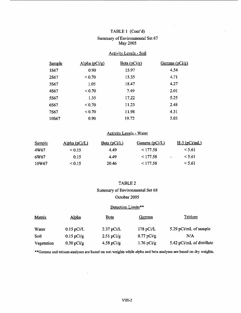
TABLE 1 (Cont'd)
Summary of Environmental Set 67May 2005
Activity Levels - Soil
Sample
1S67
2S67
3S67
4S67
5S67
6S67
7S67
10S67
Alpha (pCi/g)
0.90
<0.70
1.05
<0.70
1.35
< 0.70
< 0.70
0.90
Beta (pCi/R)
15.97
15.35
18.47
7.49
17.22
11.23
11.98
19.72
Gamma (pCi/a)
4.54
4.71
4.27
2.01
5.25
2.48
4.31
5.03
Activity Levels - Water
Sample
4W67
6W67
10W67
Alpha (pCi/U
< 0.15
0.15
<0.15
Beta (pCi/L)
4.49
4.49
20.46
Gamma (pCi/L)
< 177.58
< 177.58
< 177.58
H-3 (pCi/mL)
<5.61
< 5.61
<5.61
TABLE 2
Summary of Environmental Set 68
October 2005
Detection Limits**
Matrix
Water
Soil
Vegetation
Alpha
0.15 pCi/L
0.15 pCi/g
0.30 pCi/g
Beta
2.37 pCi/L
2.51 pCi/g
4.58 pCi/g
Gamma
178 pCi/L
0.77 pCi/g
1.76 pCi/g
Tritium
5.29 pCi/mL of sample
N/A
5.42 pCi/mL of distillate
**Gamma and tritium analyses are based on wet weights while alpha and beta analyses are based on dry weights.
VIII-2

TABLE 2 (Cont'd)
Summary of Environmental Set 68October 2005
Activity Levels - Vegetation
Sample
1V68
2V68
3V68
4V68
5V68
6V68
7V68
10V68
Alpha (pCi/g)
<0.30
< 0.30
< 0.30
< 0.30
< 0.30
< 0.30
< 0.30
< 0.30
Beta (pCi/g)
8.14
8.65
10.18
8.14
6.11
5.09
5.60
6.11
Gamma (pCi/p')
< 1.76
< 1.76
<1.76
< 1.76
< 1.76
< 1.76
< 1.76
< 1.76
H-3 (pCi/ml,
< 5.42
< 5.42
<5.42
< 5.42
< 5.42
< 5.42
< 5.42
< 5.42
Activity Levels - Soil
Sample
1S68
2S68
3S68
4S68
5S68
6S68
7S68
10S68
Alpha (pCi/g)
0.80
0.53
0.53
0.27
1.07
0.27
1.34
0.27
Beta (pCi/g)
14.25
15.27
19.85
12.47
15.52
9.42
14.89
21.12
Gamma (pCi/g)
3.13
4.15
3.84
2.26
5.30
4.85
3.70
5.70
Activity Lgvels - Water
Sample
4W68
6W68
10W68
Alpha (pCi/L)
0.27
0.27
0.27
Beta (pCi/L!
6.87
8.65
22.40
Gamma (pCi/L)
< 178
< 178
<178
H-3 (pCi/<5
< 5.29
< 5.29
< 5.29
VIII-3
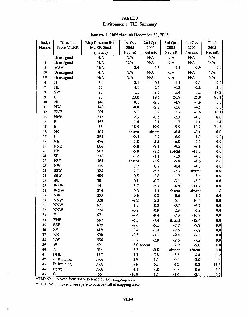
TABLE 3
Environmental TLD Summary
January 1, 2005 through December 31, 2005
Badge Direction Map Distance from 1st Qtr. 2nd Qtr. 3rd Qtr. 4th Qtr. TotalNumber From MURR MURR Stack 2005 2005 2005 2005 2005
(meters) Net mR Net mR Net mR Net mR Net mRI Unassigned2 Unassigned3 WSW4* Unassigned5** Unassigned6 N7 NE8 SW9 S10 NE11 NW12 ENE13 NNE14 S15 S16 SE17 E18 NE19 NNE20 NE21 SE22 ESE23 NW24 SSW25 SSW26 SW27 WSW28 WNW29 NW30 NNW31 NNW32 NNW33 E34 ENE35 SSE36 SE37 NE38 NW39 W40 N41 NNE42 In Building43 In Building44 Spare45 S
N/AN/AN/AN/AN/A3457272714914930131615665107293476606907236168110328480301141210255328671724671587499419690556491514137N/AN/AN/A65
N/A N/AN/A N/A
2.4 -1.3N/AN/A
N/AN/A
2.14.11.1
23.00.1
-0.85.12.31.4
18.5absent a
-3.4-1.8-5.8-5.8-1.2
absent1.7
-2.7-0.50.1
-3.70.20.6
-2.21.7
-0.8-2.4-5.3-2.60.4
-0.50.7
-3.0 absent-3.3-3.33.95.94.1
-16.9
0.82.63.5
19.6-2.3-2.73.9
-0.53.1
19.9bsent
-5.2-5.3-7.1-8.5-1.1-3.90.7
-5.5-2.8-0.2-5.71.40.2
-5.20.3
-0.9-9.4-7.4-5.1-1.4-3.1-2.0
-0.8-5.83.16.13.81.1
N/AN/A
-7.1N/AN/A
-4.1-0.35.4
26.9-4.7-2.82.7
-2.3-1.719.9-6.4-6.0-6.0-9.5
absent-1.9-5.9-0.4-7.3-1.7-3.1-8.9
absent-0.6-5.1-0.7-2.3-7.3
absent-7.7-2.6-9.8-2.6-7.9
absent-5.50.46.2
-0.8-1.6
N/AN/A
-5.9N/AN/A
-3.1-2.87.2
25.9-7.6-4.5-1.6-4.3-1.413.2-7.4-8.7-7.3-9.8
-11.2-4.3-8.0-4.2
absent-5.6-6.7
-11.2absent
-1.2-10.5-4.7
-6.3-10.9-12.4
-7.7-7.8-7.5-7.2-9.0
absent-8.4-3.00.3
-0.6-3.1
N/AN/A
N/AN/A
0.0
0.03.6
17.295.4
0.00.0
10.10.01.4
71.50.00.00.00.00.00.00.00.00.00.00.00.01.60.00.00.00.00.00.00.00.00.00.00.00.00.04.4
18.56.50.0
-
*TLD No. 4 moved from spare to fence outside shipping area.**TLD No. 5 moved from spare to outside wall of shipping area.
VIII-4

TABLE 4Number of Facility Radiation and Contamination Surveys
January 1, 2005 through December 31, 2005
JanuaryFebruaryMarchAprilMayJuneJulyAugustSeptemberOctoberNovemberDecember
TOTALS
Radiation
506145775857354943578348
663
Surface Contamination*
506145775857354943578348
663
Air Samples** RWP's
49 850 657 653 1557 959 351 854 1058 852 1353 1057 7
650 103
* In addition, general building contamination surveys are conducted each normal work day.
** Air samples include stack Ar-41, containment Ar-41, sump entries, and hot cell entries.
Miscellaneous Notes
Manual Diaz was hired as a Health Physics Technician in February 2005.
Dan Nickolaus was promoted to Health Physics Technician in June 2005.
Shaun Kelley was promoted to Health Physics Technician II in June 2005.
During calendar 2005, MURR shipped 737.55 cubic feet of low-level radioactive waste.
VIII- 5

SECTION IX
SUMMARY OF RADIATION EXPOSURES TO FACILITY STAFF,EXPERIMENTERS AND VISITORS
January 1, 2005 through December 31, 2005
TOTAL PERSONNEL DOSE (MREM) BY DOSIMETRY GROUP
MonthJanuaryFebruaryMarchAprilMayJuneJulyAugustSeptemberOctoberNovemberDecember
AC38341013116
77143014814
DO FSO HC RAG IRR NA2 355 262 157 51 1512 146 153 130 72 1011 133 169 165 45 81 447 158 208 51 108 294 235 173 72 15
74 40 221 179 58 64 95 290 175 82 1216 112 290 279 86 1419 112 346 257 100 419 251 245 299 119 167 120 224 129 173 1234 60 188 220 33 16
NS OPS PRO RP32 1607 47 9627 1366 49 11033 1374 106 6340 1455 88 2420 1282 67 5821 1282 72 6112 1442 75 9531 1748 47 3839 1465 38 857 2070 37 4717 1413 31 6620 1683 50 43
SH SIL rCI76 44 0109 78 1876 45 7119 51 0148 52 2115 128 0127 81 0138 93 0189 102 3150 73 0200 65 4255 207 1
Total278223142245266524372263256729062789334724692824
Total to Date 269 207 2165 2781 2371 942 138 299 18187 707 786 1702 1019 35 31608
Monthly Ave
Highest WB
22 17 180 232 198 79
49 28 128 201 115 146
12 25 1516 59
7 40 275 37
66 142 85
21 101 124
3 2634
18
Highest EXT 200 100 2210 660 150 270 260 100 1490 970 490 220 450 60
AC - Analytical Chemistry RAG - Health PhysicsDO - Director's Office IRR - IrradiationsFSO - Shops NA - Nuclear AnalysisHC - Hot Cell NS - Neutron Scattering
OPS - Operations SIL - SiliconPRO - Isotope Production TCI - Special ProjectRP - RadiophariceuticalSH - Shipping
WB = Whole Body EXT = Extremities
NOTE: Dosimetry services are provided by R.S. Landauer Jr. & Company (except self-reading dosimetry).
Analysis of personnel exposure levels indicates that exposures are significantly below the limits of 10 CFR 20.1201 andare generally maintained ALARA. Radiation workers who are not full time staff members have radiation exposureswhich are generally lower than full time radiation workers.
IX-1