9th International CO 2 Capture Network ENERGI E2 ...
61
9th International CO 2 Capture Network ENERGI E2, Copenhagen, June 16, 2006 Carbon Dioxide Capture and Storage activities in Denmark Ole Biede, ENERGI E2 A/S Jacob Knudsen, Elsam Engineering
Transcript of 9th International CO 2 Capture Network ENERGI E2 ...

9th International CO 2 Capture NetworkENERGI E2, Copenhagen, June 16, 2006
Carbon Dioxide Capture and Storage activities in Denmark
Ole Biede, ENERGI E2 A/S
Jacob Knudsen, Elsam Engineering

9th International CO2 Capture NetworkENERGI E2, Copenhagen, June 16, 2006
� Practical details� ENERGI E2 and Reorganization of the Danish
Power Companies� CO2 Capture and Storage activities in Denmark� CASTOR Project (Ca pture and Stor age of CO 2)� Pilot Plant� Results from the Pilot Plant

9th Int. CO2 Capture Network, Copenhagen 2006Practical details - overview
� Coffee breaks – 10.15 and 15.00� Lunch buffet – 12.30� Restrooms� Dinner in Tivoli, Restaurant Påfuglen 19.30
� Number of participants- Accompany: Keith Harrison, Bob Stobbs, John Topper
� Dietary requirements- No beef: Andy Aroonwilas, Amy Weawab
� Tickets� Map� Tivoli closes at 00.30

9th Int. CO2 Capture Network, Copenhagen 2006Practical details - maps
Kong Frederik
Absalon
Tivoli

9th Int. CO2 Capture Network, Copenhagen 2006Practical details - Tivoli
Entrance
Dinner atPåfuglen19.30
9th International CO2 Capture NetworkE2, Copenhagen, June 16, 2006
ENERGI E2 and
Reorganization of theDanish Power Companies

9th Int. CO2 Capture Network, Copenhagen 2006ENERGI E2
� ENERGI E2 is a leading Danish energy production and trading company
� E2 owns and operates 17 power and combined heat and power plants in Eastern Denmark and has several activities internationally
� E2’s head office is located in Copenhagen with approximately 400 employees
� In total E2 has 1450 employees
� Total production capacity:4.800 MW electricity, 2.850 MJ/s heat and 1.800 MJ/s steam.

9th Int. CO2 Capture Network, Copenhagen 2006ENERGI E2 – power plants
Central power stations
Minor combined heat and power plants
HelsingørHillerødHundested
Kyndbyværket
DTU, Lyngby
Avedøreværket
Masnedø
Stigsnæsværket
SlagelseRingsted
Haslev
Cable to Sweden
Cable to Germany
Maribo/Sakskøbing
Svanemølleværket
H.C. Ørsted Værket
Amagerværket
Hovedkontor, Sydhavnen
Head officeOff shore wind mill farm
Køge
NystedBiommass pellets production

9th Int. CO2 Capture Network, Copenhagen 2006ENERGI E2 - international
Pax
Utgrunden
Fanbyn
Yttre Stengrund
Narvik Energi
CRISA
Ascoy
Desebro & Ceasa
Juneda VAG, Rubi og Mataro
Pico Gallo wind farm
Karistos og Tourla
Indalsälven
Bodenaya
Santa Quiteria
Giribaile
Carcelen
Wind mill parks
Hydro power
Biomass
Off shore windr
Klimpfjäll
SaltenKraftsamband

9th Int. CO2 Capture Network, Copenhagen 2006ENERGI E2, Avedøre Power Station

9th Int. CO2 Capture Network, Copenhagen 2006Reorganization of the Danish Power Companies
Before After1. July 2006
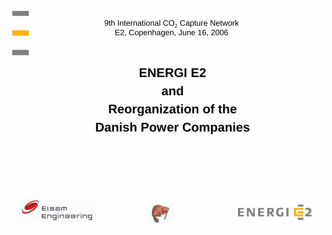
9th Int. CO2 Capture Network, Copenhagen 2006Reorganization of the Danish Power Companies
DONG: 75%Vattenfall: 25%

9th International CO2 Capture NetworkE2, Copenhagen, June 16, 2006
CO2 Capture and Storage activities in Denmark
� Kalundborg� CENS� EU-projects: CO2store, ENCAP, Castor

9th Int. CO2 Capture Network, Copenhagen 2006Carbon Dioxide Capture & Storage activities in Denmark - Kalundborg
Geological Survey of Denmark and Greenland, GEUS
Saline aquifer storage of CO 2 from major point sources –a Danish case study

9th Int. CO2 Capture Network, Copenhagen 2006Carbon Dioxide Capture & Storage activities in Denmark - Kalundborg
Asnæs Power Station
HavnsøSaline aquifer
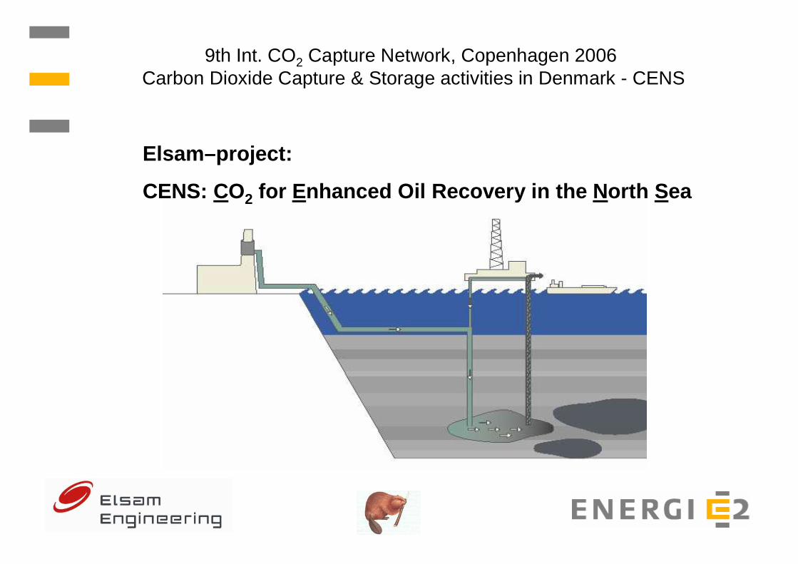
9th Int. CO2 Capture Network, Copenhagen 2006Carbon Dioxide Capture & Storage activities in Denmark - CENS
Elsam–project:
CENS: CO2 for E nhanced Oil Recovery in the N orth S ea

9th Int. CO2 Capture Network, Copenhagen 2006Carbon Dioxide Capture & Storage activities in Denmark - CENS
Esbjergværket today
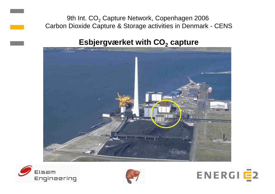
9th Int. CO2 Capture Network, Copenhagen 2006Carbon Dioxide Capture & Storage activities in Denmark - CENS
Esbjergværket with CO 2 capture
9th Int. CO2 Capture Network, Copenhagen 2006Carbon Dioxide Capture & Storage activities in Denmark - CENS
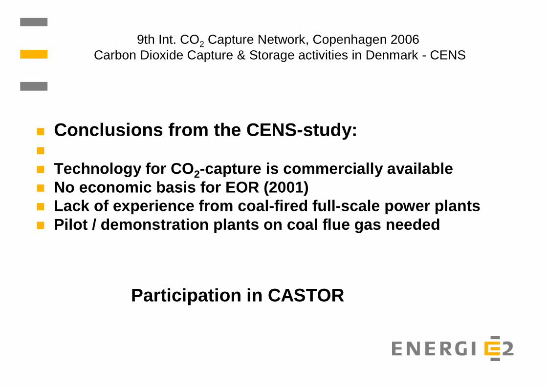
� Conclusions from the CENS-study:�
� Technology for CO 2-capture is commercially available� No economic basis for EOR (2001) � Lack of experience from coal-fired full-scale power plan ts� Pilot / demonstration plants on coal flue gas needed
Participation in CASTOR

9th International CO2 Capture Network, ENERGI E2, Copenhagen, June 16, 2006
CASTOR Project”Ca pture and Stor age of CO 2”
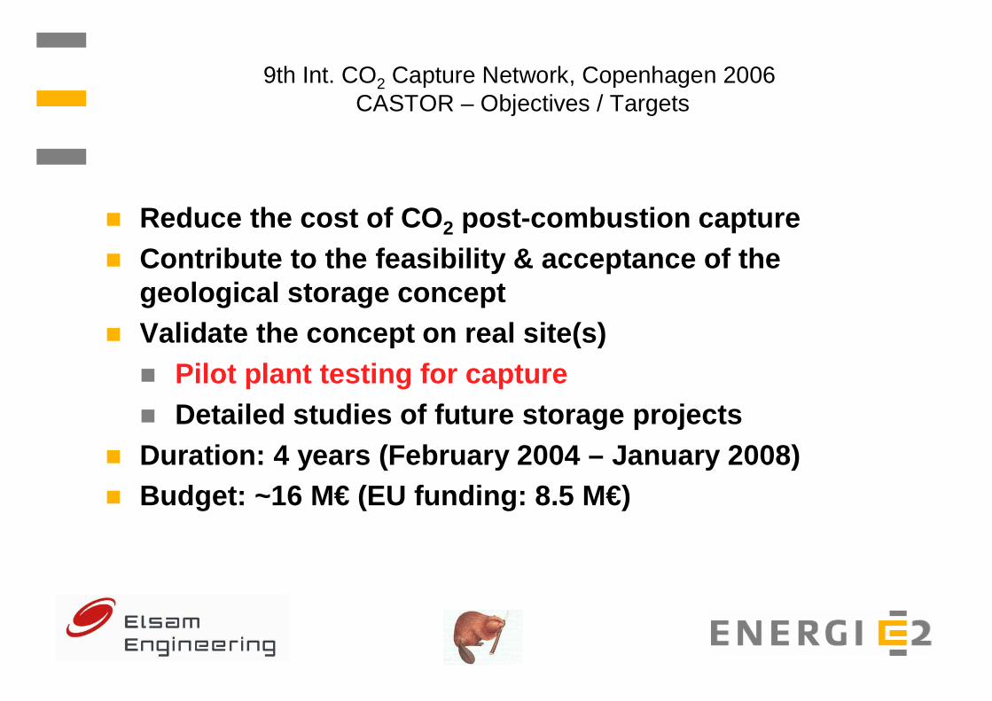
9th Int. CO2 Capture Network, Copenhagen 2006CASTOR – Objectives / Targets
� Reduce the cost of CO 2 post-combustion capture� Contribute to the feasibility & acceptance of the
geological storage concept� Validate the concept on real site(s)
� Pilot plant testing for capture� Detailed studies of future storage projects
� Duration: 4 years (February 2004 – January 2008)� Budget: ~16 M€ (EU funding: 8.5 M€)
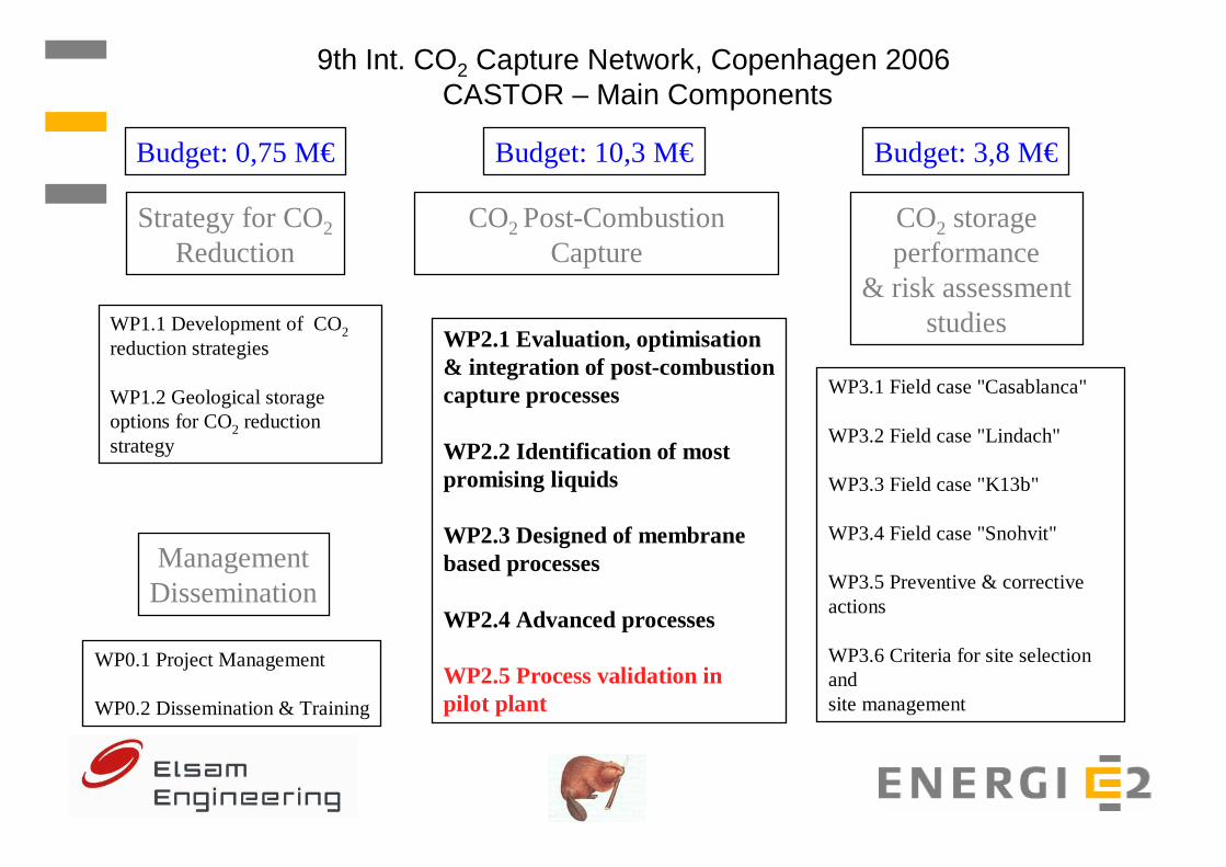
9th Int. CO2 Capture Network, Copenhagen 2006CASTOR – Main Components
Strategy for CO2Reduction
WP1.1 Development of CO2reduction strategies
WP1.2 Geological storageoptions for CO2 reductionstrategy
CO2 Post-CombustionCapture
WP2.1 Evaluation, optimisation& integration of post-combustioncapture processes
WP2.2 Identification of mostpromising liquids
WP2.3 Designed of membranebased processes
WP2.4 Advanced processes
WP2.5 Process validation inpilot plant
CO2 storageperformance
& risk assessmentstudies
WP3.1 Field case "Casablanca"
WP3.2 Field case "Lindach"
WP3.3 Field case "K13b"
WP3.4 Field case "Snohvit"
WP3.5 Preventive & correctiveactions
WP3.6 Criteria for site selection andsite management
ManagementDissemination
WP0.1 Project Management
WP0.2 Dissemination & Training
Budget: 0,75 M€ Budget: 10,3 M€ Budget: 3,8 M€
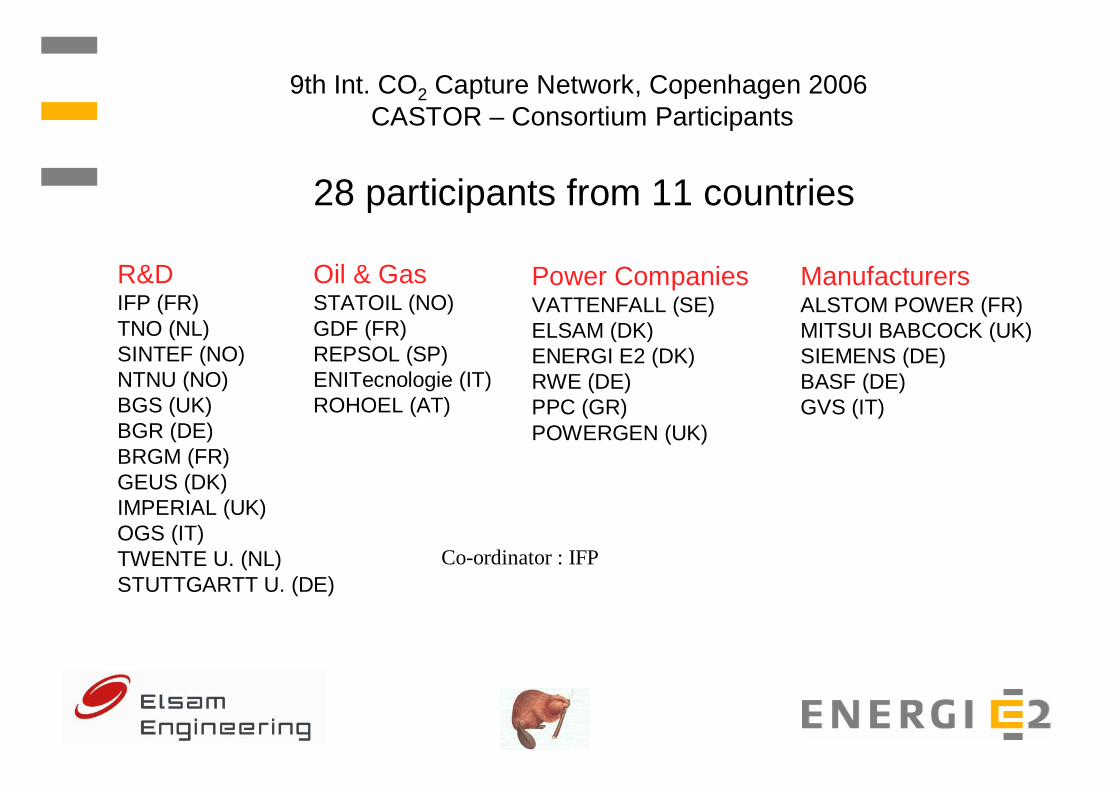
9th Int. CO2 Capture Network, Copenhagen 2006CASTOR – Consortium Participants
R&DIFP (FR)TNO (NL)SINTEF (NO)NTNU (NO)BGS (UK)BGR (DE)BRGM (FR)GEUS (DK)IMPERIAL (UK)OGS (IT)TWENTE U. (NL)STUTTGARTT U. (DE)
Oil & GasSTATOIL (NO)GDF (FR)REPSOL (SP)ENITecnologie (IT)ROHOEL (AT)
Power CompaniesVATTENFALL (SE)ELSAM (DK)ENERGI E2 (DK)RWE (DE)PPC (GR)POWERGEN (UK)
ManufacturersALSTOM POWER (FR)MITSUI BABCOCK (UK)SIEMENS (DE)BASF (DE)GVS (IT)
Co-ordinator : IFP
28 participants from 11 countries

9th International CO2 Capture Network, ENERGI E2, Copenhagen, June 16, 2006
Castor Pilot Plant

9th Int. CO2 Capture Network, Copenhagen 2006CASTOR – Time schedule
February 2004 : Castor project startsSeptember 2004 : Invitation for tender issuedFebruary 2005 : Contract awarded – TPI, ItalyJuly 2005 : Erection startOctober 2005 : Commissioning start January 2006 : Start Test Phase 1, 1000 h on 30% MEAMarch 2006 : End Test Phase 1August 2006 : Start Test Phase 2, 1000 h on 30% MEAFall 2006: : Start Test Phase 3, 4000 h on Castor1Summer 2007 : Start Test Phase 4, 4000 h on Castor2January 2008 : End of Castor

9th Int. CO2 Capture Network, Copenhagen 2006CASTOR – Pilot plant at Esbjergværket
Castor Pilot Plant
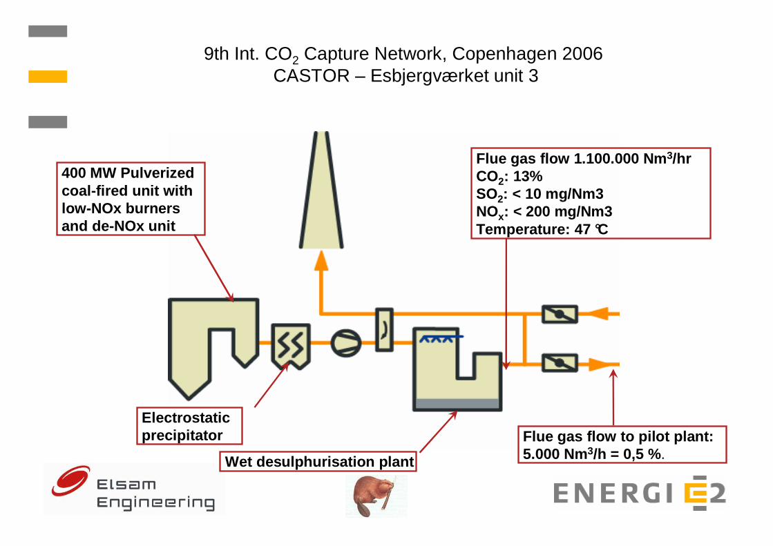
9th Int. CO2 Capture Network, Copenhagen 2006CASTOR – Esbjergværket unit 3
400 MW Pulverizedcoal-fired unit withlow-NOx burnersand de-NOx unit
Flue gas flow 1.100.000 Nm 3/hrCO2: 13%SO2: < 10 mg/Nm3NOx: < 200 mg/Nm3Temperature: 47 °C
Flue gas flow to pilot plant: 5.000 Nm3/h = 0,5 %.Wet desulphurisation plant
Electrostaticprecipitator

Flue Gas In
Mechanical Filters
Carbon Filter
Reclaimer
Sea Water In
Lean MEARich MEA
Auxiliary Steam
Cleaned Flue Gas Out CO2 Out
Sea Water Out
Soda
Internal Cooling Circuit
Reboiler
MEA/MEA Cooler
ABSORBERSTRIPPER
Flue Gas Wash Water
CO2 Wash Water
To Flue Gas Wash Water
9th Int. CO2 Capture Network, Copenhagen 2006CASTOR – Pilot plant
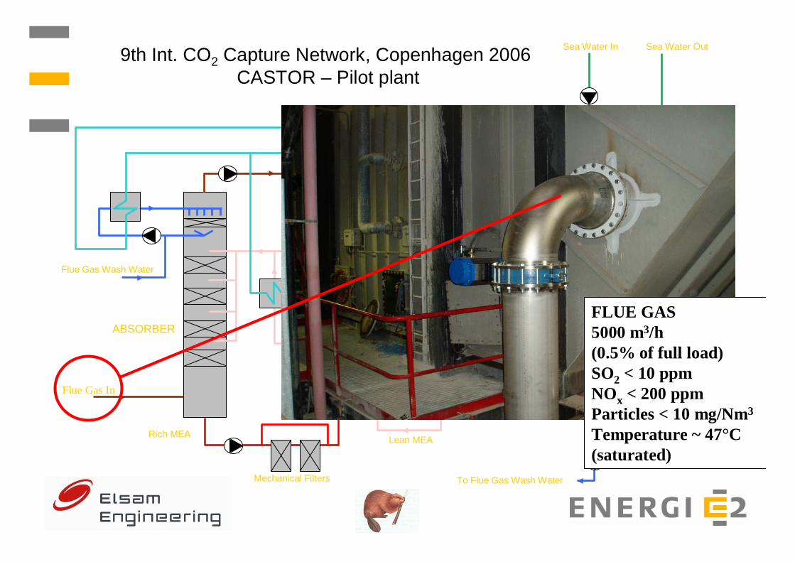
Flue Gas In
Carbon Filter
Reclaimer
Sea Water In
Lean MEARich MEA
Auxiliary Steam
Cleaned Flue Gas Out CO2 Out
Sea Water Out
Soda
Internal Cooling Circuit
Reboiler
MEA/MEA Cooler
ABSORBERSTRIPPER
Flue Gas Wash Water
CO2 Wash Water
To Flue Gas Wash Water
9th Int. CO2 Capture Network, Copenhagen 2006CASTOR – Pilot plant
FLUE GAS 5000 m3/h (0.5% of full load) SO2 < 10 ppmNOx < 200 ppmParticles < 10 mg/Nm3
Temperature ~ 47°C (saturated)
Mechanical Filters

Flue Gas In5.000 Nm3/h13 % CO247 grC
Mechanical Filters
Carbon Filter
Reclaimer
Sea Water In
Lean MEARich MEA
Auxiliary Steam
Cleaned Flue Gas Out CO2 Out
Sea Water Out
Soda
Internal Cooling Circuit
Reboiler
MEA/MEA Cooler
ABSORBERSTRIPPER
Flue Gas Wash Water
CO2 Wash Water
To Flue Gas Wash Water
9th Int. CO2 Capture Network, Copenhagen 2006CASTOR – Pilot plant
Flue Gas In
Mechanical Filters
Carbon Filter
Reclaimer
Sea Water In
Lean MEARich MEA
Auxiliary Steam
Cleaned Flue Gas Out CO2 Out
Sea Water Out
Soda
Internal Cooling Circuit
Reboiler
MEA/MEA Cooler
ABSORBERSTRIPPER
Flue Gas Wash Water
CO2 Wash Water
To Flue Gas Wash Water
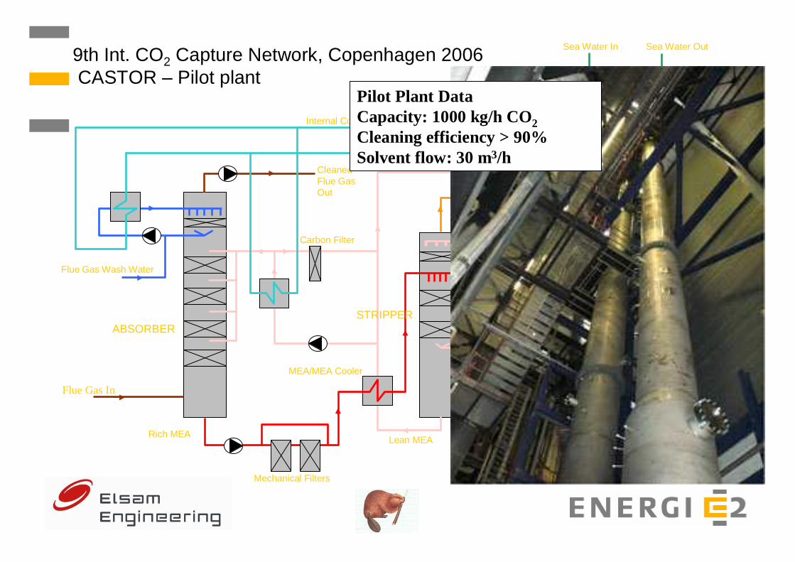
9th Int. CO2 Capture Network, Copenhagen 2006CASTOR – Pilot plant
Pilot Plant Data Capacity: 1000 kg/h CO2Cleaning efficiency > 90% Solvent flow: 30 m3/h

Flue Gas In
Carbon Filter
Reclaimer
Sea Water In
Lean MEARich MEA
Auxiliary Steam
Cleaned Flue Gas Out CO2 Out
Sea Water Out
Soda
Internal Cooling Circuit
Reboiler
MEA/MEA Cooler
ABSORBERSTRIPPER
Flue Gas Wash Water
CO2 Wash Water
To Flue Gas Wash Water
9th Int. CO2 Capture Network, Copenhagen 2006CASTOR – Pilot plant
Absorber sump: round 6.7 m3 MEA
Mechanical Filters

Flue Gas In
Carbon Filter
Reclaimer
Sea Water In
Lean MEARich MEA
Auxiliary Steam
Cleaned Flue Gas Out CO2 Out
Sea Water Out
Soda
Internal Cooling Circuit
Reboiler
MEA/MEA Cooler
ABSORBERSTRIPPER
Flue Gas Wash Water
CO2 Wash Water
To Flue Gas Wash Water
9th Int. CO2 Capture Network, Copenhagen 2006CASTOR – Pilot plant
RANDOM PACKINGS for absorber and stripper IMTP-50
Mechanical Filters
Flue Gas In
Carbon Filter
Reclaimer
Sea Water In
Lean MEARich MEA
Auxiliary Steam
Cleaned Flue Gas Out CO2 Out
Sea Water Out
Soda
Internal Cooling Circuit
Reboiler
MEA/MEA Cooler
ABSORBERSTRIPPER
Flue Gas Wash Water
CO2 Wash Water
To Flue Gas Wash Water
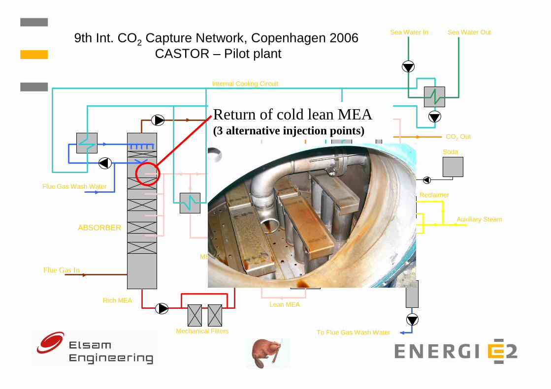
9th Int. CO2 Capture Network, Copenhagen 2006CASTOR – Pilot plant
Return of cold lean MEA (3 alternative injection points)
Mechanical Filters
Flue Gas In
Carbon Filter
Reclaimer
Sea Water In
Lean MEARich MEA
Auxiliary Steam
Cleaned Flue Gas Out CO2 Out
Sea Water Out
Soda
Internal Cooling Circuit
Reboiler
MEA/MEA Cooler
ABSORBERSTRIPPER
Flue Gas Wash Water
CO2 Wash Water
To Flue Gas Wash Water
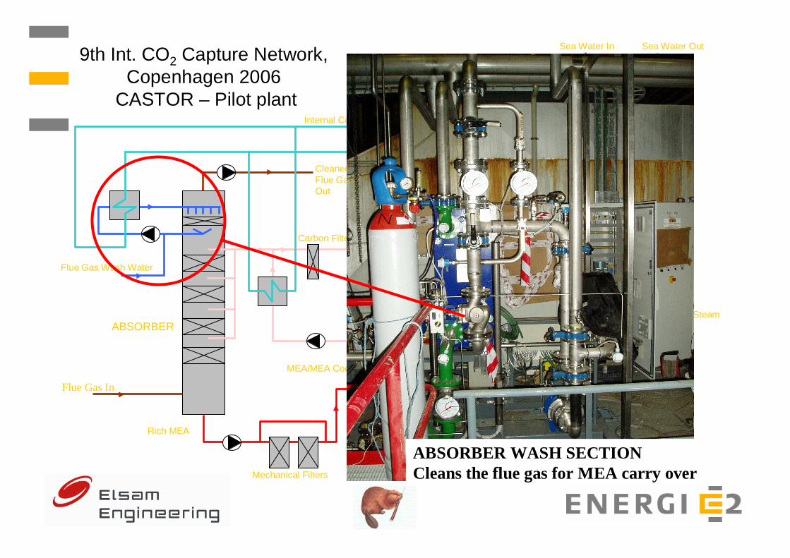
9th Int. CO2 Capture Network, Copenhagen 2006
CASTOR – Pilot plant
ABSORBER WASH SECTION Cleans the flue gas for MEA carry overMechanical Filters

Flue Gas In
Carbon Filter
Reclaimer
Sea Water In
Lean MEARich MEA
Auxiliary Steam
Cleaned Flue Gas Out CO2 Out
Sea Water Out
Soda
Internal Cooling Circuit
Reboiler
MEA/MEA Cooler
ABSORBERSTRIPPER
Flue Gas Wash Water
CO2 Wash Water
To Flue Gas Wash Water
9th Int. CO2 Capture Network, Copenhagen 2006CASTOR – Pilot plant
FLUE GAS FAN Sucks the flue gas back to the main flue gas ductMechanical Filters

Flue Gas In
Carbon Filter
Reclaimer
Sea Water In
Lean MEARich MEA
Auxiliary Steam
Cleaned Flue Gas Out
CO2 Out
Sea Water Out
Soda
Internal Cooling Circuit
Reboiler
MEA/MEA Cooler
ABSORBERSTRIPPER
Flue Gas Wash Water
CO2 Wash Water
To Flue Gas Wash Water
9th Int. CO2 Capture Network, Copenhagen 2006CASTOR – Pilot plant
CLEANED FLUE GAS Return from absorber to flue gas duct after air preheaterMechanical Filters

Flue Gas In
Carbon Filter
Reclaimer
Sea Water In
Lean MEARich MEA
Auxiliary Steam
Cleaned Flue Gas Out CO2 Out
Sea Water Out
Soda
Internal Cooling Circuit
Reboiler
MEA/MEA Cooler
ABSORBERSTRIPPER
Flue Gas Wash Water
CO2 Wash Water
To Flue Gas Wash Water
9th Int. CO2 Capture Network, Copenhagen 2006
CASTOR – Pilot plant
CARBON FILTERS Clean rich MEA from absorber
MEA/MEA HEAT EXCHANGER Heats rich MEA from absorber before entering stripper
Cools lean MEA from stripper before entering trim cooler and absorberMechanical Filters

Flue Gas In
Carbon Filter
Reclaimer
Sea Water In
Lean MEARich MEA
Auxiliary Steam
Cleaned Flue Gas Out CO2 Out
Sea Water Out
Soda
Internal Cooling Circuit
Reboiler
MEA/MEA Cooler
ABSORBERSTRIPPER
Flue Gas Wash Water
CO2 Wash Water
To Flue Gas Wash Water
9th Int. CO2 Capture Network, Copenhagen 2006CASTOR – Pilot plant
Injection of hot rich MEA (~110°C)
Mechanical Filters
Flue Gas In
Carbon Filter
Reclaimer
Sea Water In
Lean MEARich MEA
Auxiliary Steam
Cleaned Flue Gas Out CO2 Out
Sea Water Out
Soda
Internal Cooling Circuit
Reboiler
MEA/MEA Cooler
ABSORBERSTRIPPER
Flue Gas Wash Water
CO2 Wash Water
To Flue Gas Wash Water
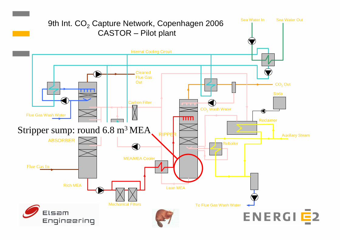
9th Int. CO2 Capture Network, Copenhagen 2006CASTOR – Pilot plant
Stripper sump: round 6.8 m3 MEA
Mechanical Filters
Flue Gas In
Carbon Filters
Carbon Filter
Reclaimer
Sea Water In
Lean MEARich MEA
Auxiliary Steam
Cleaned Flue Gas Out CO2 Out
Sea Water Out
Soda
Internal Cooling Circuit
Reboiler
MEA/MEA Cooler
ABSORBERSTRIPPER
Flue Gas Wash Water
CO2 Wash Water
To Flue Gas Wash Water
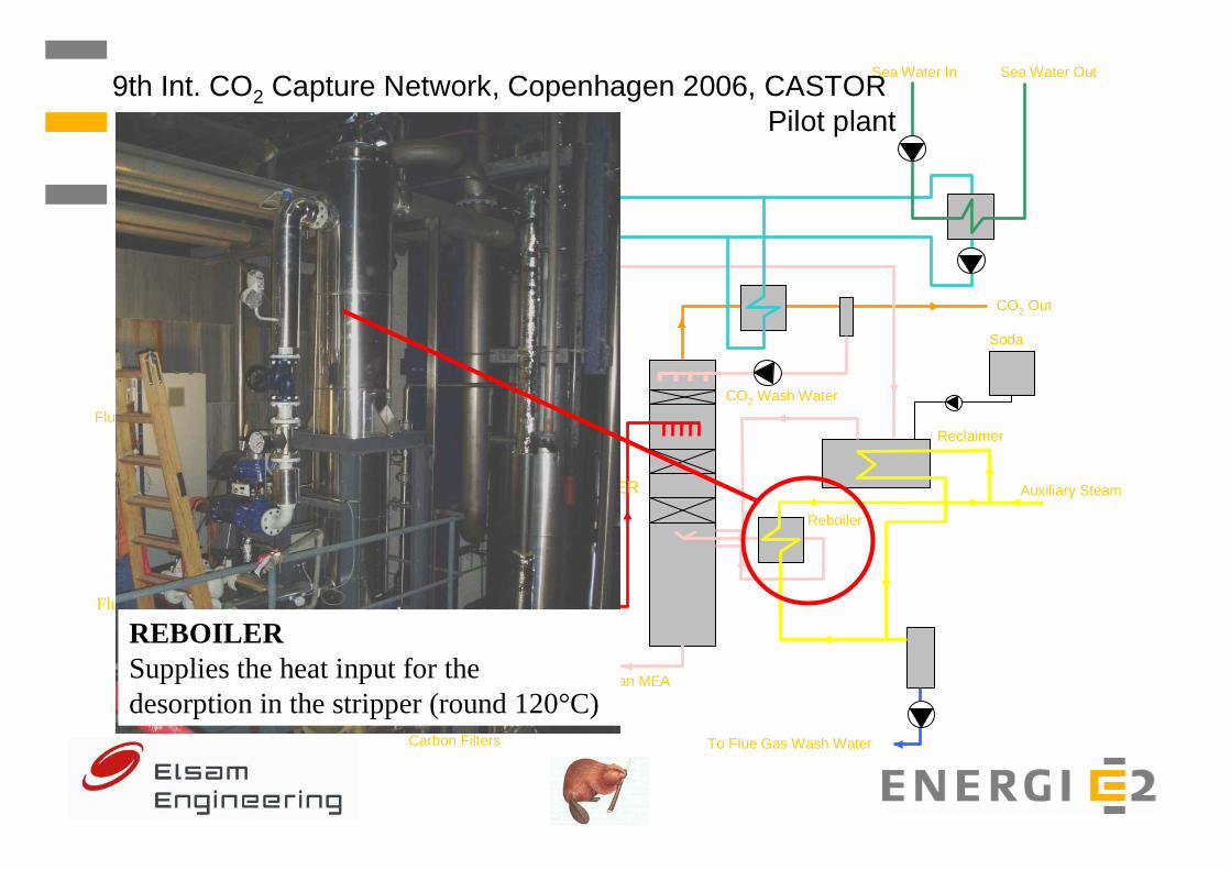
9th Int. CO2 Capture Network, Copenhagen 2006, CASTOR Pilot plant
REBOILER Supplies the heat input for the desorption in the stripper (round 120°C)

Flue Gas In
Carbon Filter
Reclaimer
Sea Water In
Lean MEARich MEA
Auxiliary Steam
Cleaned Flue Gas Out CO2 Out
Sea Water Out
Soda
Internal Cooling Circuit
Reboiler
MEA/MEA Cooler
ABSORBERSTRIPPER
Flue Gas Wash Water
CO2 Wash Water
To Flue Gas Wash Water
9th Int. CO2 Capture Network, Copenhagen 2006CASTOR – Pilot plant
Mechanical Filters
LEAN MEA COOLER AND FILTER Extra cooling of lean MEA before return to absorber. A part of the MEA flow is cleaned in carbon filter
Flue Gas In
Carbon Filters
Carbon Filter
Reclaimer
Sea Water In
Lean MEARich MEA
Auxiliary Steam
Cleaned Flue Gas Out CO2 Out
Sea Water Out
Soda
Internal Cooling Circuit
Reboiler
MEA/MEA Cooler
ABSORBERSTRIPPER
Flue Gas Wash Water
CO2 Wash Water
To Flue Gas Wash Water
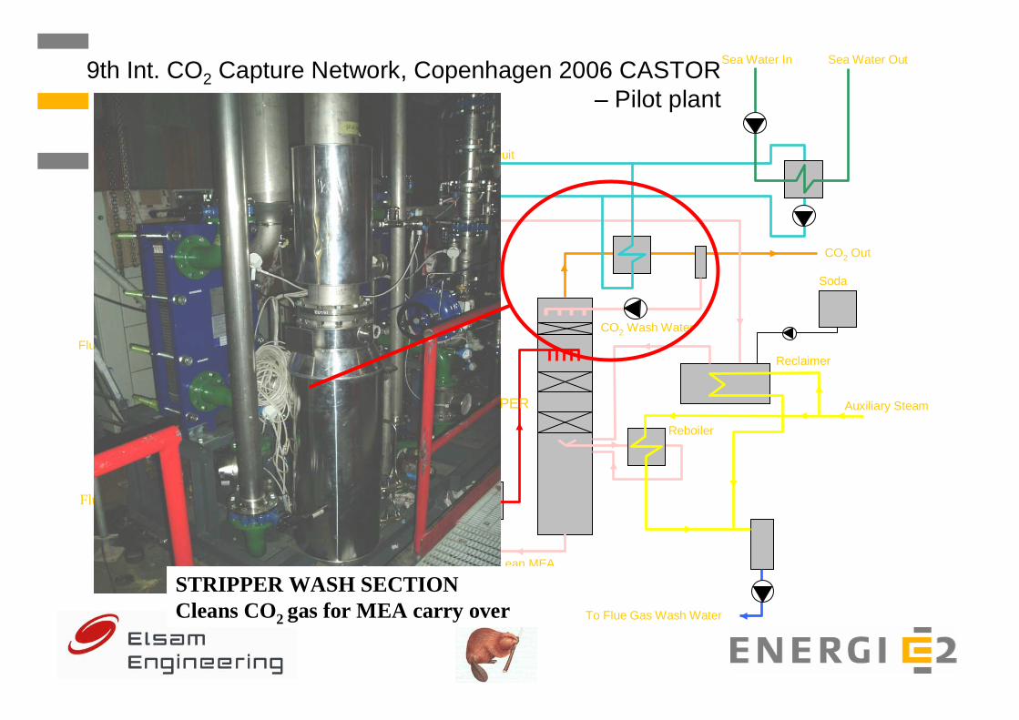
9th Int. CO2 Capture Network, Copenhagen 2006 CASTOR – Pilot plant
STRIPPER WASH SECTION Cleans CO2 gas for MEA carry over

Flue Gas In
Carbon Filters
Carbon Filter
Reclaimer
Sea Water In
Lean MEARich MEA
Auxiliary Steam
Cleaned Flue Gas Out CO2 Out
Sea Water Out
Soda
Internal Cooling Circuit
Reboiler
MEA/MEA Cooler
ABSORBERSTRIPPER
Flue Gas Wash Water
CO2 Wash Water
To Flue Gas Wash Water
9th Int. CO2 Capture Network, Copenhagen 2006CASTOR – Pilot plant
CO2 PRODUCT GAS FROM STRIPPER Return from stripper to flue gas duct after air preheater (round 1000 kg/h)

Flue Gas In
Carbon Filter
Reclaimer
Sea Water In
Lean MEARich MEA
Auxiliary Steam
Cleaned Flue Gas Out CO2 Out
Sea Water Out
Soda
Internal Cooling Circuit
Reboiler
MEA/MEA Cooler
ABSORBERSTRIPPER
Flue Gas Wash Water
CO2 Wash Water
To Flue Gas Wash Water
9th Int. CO2 Capture Network, Copenhagen 2006CASTOR – Pilot plant
SEA WATER COOLING CIRCUIT Supplies sea cooling water to internal fresh water cooling circuit
Mechanical Filters

Flue Gas In
Carbon Filters
Carbon Filter
Reclaimer
Sea Water In
Lean MEARich MEA
Auxiliary Steam
Cleaned Flue Gas Out CO2 Out
Sea Water Out
Soda
Internal Cooling Circuit
Reboiler
MEA/MEA Cooler
ABSORBERSTRIPPER
Flue Gas Wash Water
CO2 Wash Water
To Flue Gas Wash Water
9th Int. CO2 Capture Network, Copenhagen 2006CASTOR – Pilot plant
FRESH WATER COOLING CIRCUIT Supplies fresh cooling water to:
- Absorber wash section
- Stripper wash section
- MEA cooling section
Flue Gas In
Carbon Filter
Reclaimer
Sea Water In
Lean MEARich MEA
Auxiliary Steam
Cleaned Flue Gas Out CO2 Out
Sea Water Out
Soda
Internal Cooling Circuit
Reboiler
MEA/MEA Cooler
ABSORBERSTRIPPER
Flue Gas Wash Water
CO2 Wash Water
To Flue Gas Wash Water
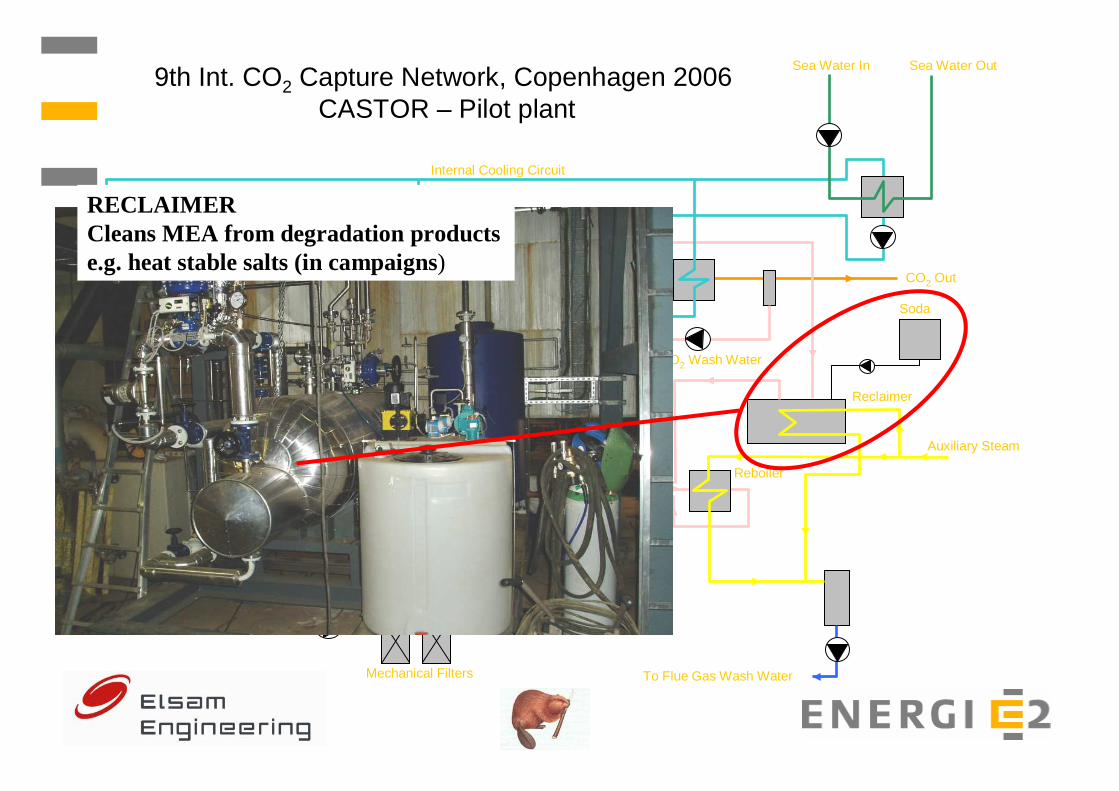
9th Int. CO2 Capture Network, Copenhagen 2006CASTOR – Pilot plant
RECLAIMERCleans MEA from degradation products e.g. heat stable salts (in campaigns)
Mechanical Filters

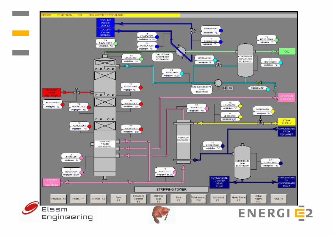
9th Int. CO2 Capture Network, Copenhagen 2006, CASTOR – Pilot plant
9th International CO2 Capture NetworkE2, Copenhagen, June 16, 2006
� Results from the Pilot Plant

Objectives - 1000 hours MEA campaign
� Functional test of the pilot plant
� Gain of operating experience
� Information on operating costs (e.g. energy & solvent
consumptions)
� Verification of theoretical models

Test program – 1000 hours MEA campaign
� Test 1 – 500 hours of continuous operation (10/01/06 - 01/02/06)
� Test 2 – Parametric study (07/02/06 -15/02/06)
� Test 3 – Special interest experiments (20/02/06 - 02/03/06)
a) Load following capability
b) Minimizing the solvent flowc) Changing the regeneration temperature
d) Optimizing the regeneration conditions
a) Absorber pressure drop (IFP)
b) SO2 injection incl. extended gas and solvent analyses (RWE & TNO)
- Continuous operation at the nominal conditions, achieving 90% CO2 capture
- Corrosion tests (IFP)

Test 1 - Summary
� Continuous operation from Jan 10th to Feb 1st
� Plant operated at settings recommended by the contractor:
� 18 outages during the test. Total down time: ≈20 hours
� Causes: High SO2, high levels, plugging of sea water filter
� Frequent plugging of solvent filter (gypsum, fly ash)
� Fresh MEA added to compensate for losses
� No reclaiming during the test
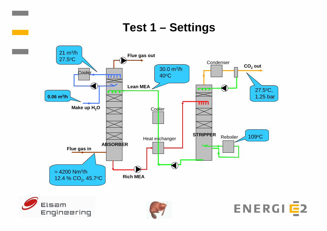
Test 1 – Settings
Flue gas in
Lean MEA
Flue gas out
CO2 out
Reboiler
ABSORBER
STRIPPER
Make up H 2O
Condenser
≈ 4200 Nm3/h12.4 % CO2, 45.7oC Rich MEA
30.0 m3/h40oC
Cooler
Cooler
27.5oC, 1.25 bar
21 m3/h 27.5oC
109oCHeat exchanger
0.06 m3/h

Test 1 – CO2 recovery
0
20
40
60
80
100
26-01-06 28-01-06 30-01-06 01-02-06
CO
2 co
nten
t & r
ecov
ery
(%)
0
1000
2000
3000
4000
5000
Flu
e ga
s (N
m3 /h
)
CO2 in flue gas CO2 recovery Flue gas
Average (26/01/06 - 01/02/06):
• CO2 recovery: 92.5% • Flue gas flow: 4170 Nm3/h (12.4% CO2) • CO2 production: 850 kg/h
Pilot plant failure

Test 1 – Absorber & Stripper temperatures
0
20
40
60
80
100
120
26-01-06 28-01-06 30-01-06 01-02-06
Tem
pera
ture
(oC
)
Absorber pos. 1-5
Stripper pos. 1-3
Pilot plant failure

Test 1 – MEA % and CO 2 loadings
0
5
10
15
20
25
30
10-01-06 15-01-06 20-01-06 25-01-06 30-01-06
ME
A c
once
ntra
tion
(% w
/w)
MEA conc. Corr. MEA conc.
0.0
0.1
0.2
0.3
0.4
0.5
10-01-06 15-01-06 20-01-06 25-01-06 30-01-06
CO
2 lo
adin
g (m
ol/m
ol)
Lean Rich
Average value:
• Lean loading: 0.24 • Rich loading: 0.37 (not reliable)•MEA: 25.7 %
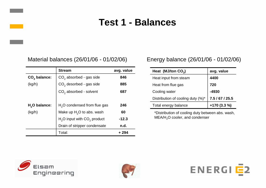
Test 1 - Balances
+ 294Total:
n.d.Drain of stripper condensate
-12.3H2O input with CO2 product
60Make up H2O to abs. wash (kg/h)
246H2O condensed from flue gasH2O balance:
687CO2 absorbed - solvent
885CO2 desorbed - gas side (kg/h)
846CO2 absorbed - gas side CO2 balance:
avg. valueStream
7.5 / 67 / 25.5Distribution of cooling duty (%)*
+170 (3.3 %)Total energy balance
-4930 Cooling water
720Heat from flue gas
4400Heat input from steam
avg. valueHeat (MJ/ton CO2)
*Distribution of cooling duty between abs. wash, MEA/H2O cooler, and condenser
Material balances (26/01/06 - 01/02/06) Energy balance (26/01/06 - 01/02/06)
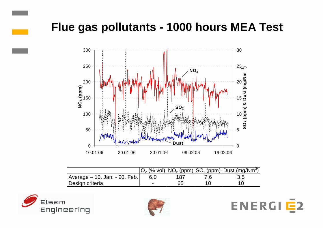
Flue gas pollutants - 1000 hours MEA Test
0
50
100
150
200
250
300
10.01.06 20.01.06 30.01.06 09.02.06 19.02.06
NO
x (p
pm)
0
5
10
15
20
25
30
SO
2 (p
pm) &
Dus
t (m
g/N
m3 )
NOx
SO2
Dust
O2 (% vol) NOx (ppm) SO2 (ppm) Dust (mg/Nm3) Average – 10. Jan. - 20. Feb. 6,0 187 7,6 3,5 Design criteria - 65 10 10
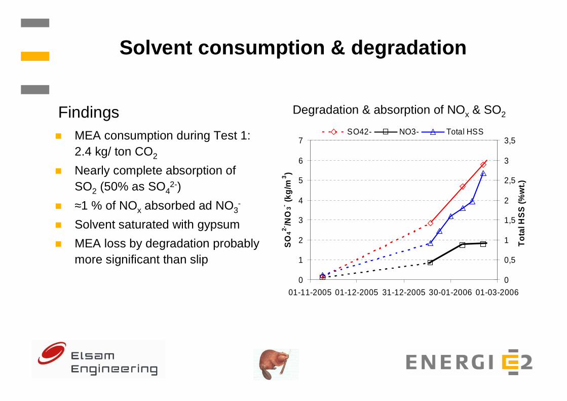
Solvent consumption & degradation
� MEA consumption during Test 1: 2.4 kg/ ton CO2
� Nearly complete absorption of SO2 (50% as SO4
2-)
� ≈1 % of NOx absorbed ad NO3-
� Solvent saturated with gypsum
� MEA loss by degradation probably more significant than slip
Degradation & absorption of NOx & SO2Findings
0
1
2
3
4
5
6
7
01-11-2005 01-12-2005 31-12-2005 30-01-2006 01-03-2006S
O4
2-/N
O3- (k
g/m
3)
0
0,5
1
1,5
2
2,5
3
3,5
Tot
al H
SS
(%w
t.)
SO42- NO3- Total HSS

Upcoming activities at Esbjerg pilot plant
� Additional campaign with MEA (Summer 2006 )
� Campaign with new solvent ”Castor 1” (Autumn 2006 -2007)
� Campaign with new solvent ”Castor 2” (2007)