
981-0604 I6 201202 · The engine exhaust from this product contains chemicals known to the State of...
56
Installation Manual RV Generator Set KV (Spec A−M) Microlite t 2800 Series English − Original Instructions 2−2012 981−0604 (Issue 6)
Transcript of 981-0604 I6 201202 · The engine exhaust from this product contains chemicals known to the State of...

Installation Manual
RV Generator Set
KV (Spec A−M)
Microlite � 2800 Series
English − Original Instructions 2−2012 981−0604 (Issue 6)

The engine exhaust from this productcontains chemicals known to the State
of California to cause cancer, birth defects or other reproductive harm.
! !

i
Table of Contents
SECTION TITLE PAGE
Safety Precautions iii . . . . . . . . . . . . . . . . . . . . . . . . . . . . . . . . . . . . . . . . . . . . . . .
General Precautions iii . . . . . . . . . . . . . . . . . . . . . . . . . . . . . . . . . . . . . . . . . . . . . . Generator Voltage is Deadly! iii . . . . . . . . . . . . . . . . . . . . . . . . . . . . . . . . . . . . . . . Battery Gas is Explosive iv . . . . . . . . . . . . . . . . . . . . . . . . . . . . . . . . . . . . . . . . . . . Moving Parts Can Cause Severe Personal Injury or Death iv . . . . . . . . . . . . . Engine Exhaust is Deadly! iv . . . . . . . . . . . . . . . . . . . . . . . . . . . . . . . . . . . . . . . . . The Hazards of Carbon Monoxide iv . . . . . . . . . . . . . . . . . . . . . . . . . . . . . . . . . . Only You Can Protect Yourself From CO Poisoning! iv . . . . . . . . . . . . . . . . . . . Substances Hazardous to Health iv . . . . . . . . . . . . . . . . . . . . . . . . . . . . . . . . . . . Fuel Is Flammable and Explosive iv . . . . . . . . . . . . . . . . . . . . . . . . . . . . . . . . . . . Propane iv . . . . . . . . . . . . . . . . . . . . . . . . . . . . . . . . . . . . . . . . . . . . . . . . . . . . . . . . . Hazardous Reactions v . . . . . . . . . . . . . . . . . . . . . . . . . . . . . . . . . . . . . . . . . . . . . Protective Measures v . . . . . . . . . . . . . . . . . . . . . . . . . . . . . . . . . . . . . . . . . . . . . . Storage/Transport v . . . . . . . . . . . . . . . . . . . . . . . . . . . . . . . . . . . . . . . . . . . . . . . . Emergency Action v . . . . . . . . . . . . . . . . . . . . . . . . . . . . . . . . . . . . . . . . . . . . . . . . Petrol (UK) / Gasoline vi . . . . . . . . . . . . . . . . . . . . . . . . . . . . . . . . . . . . . . . . . . . . . Hazardous Reactions vi . . . . . . . . . . . . . . . . . . . . . . . . . . . . . . . . . . . . . . . . . . . . . Protective Measures vi . . . . . . . . . . . . . . . . . . . . . . . . . . . . . . . . . . . . . . . . . . . . . . Storage/Transport vi . . . . . . . . . . . . . . . . . . . . . . . . . . . . . . . . . . . . . . . . . . . . . . . . Emergency Action vi . . . . . . . . . . . . . . . . . . . . . . . . . . . . . . . . . . . . . . . . . . . . . . . . Lubrication Oil − Premium Blue E 15W40 vii . . . . . . . . . . . . . . . . . . . . . . . . . . . Hazardous Reactions vii . . . . . . . . . . . . . . . . . . . . . . . . . . . . . . . . . . . . . . . . . . . . Protective Measures vii . . . . . . . . . . . . . . . . . . . . . . . . . . . . . . . . . . . . . . . . . . . . . Storage/Transport vii . . . . . . . . . . . . . . . . . . . . . . . . . . . . . . . . . . . . . . . . . . . . . . . Generator Set Warning Labels viii . . . . . . . . . . . . . . . . . . . . . . . . . . . . . . . . . . . .
1 Introduction 1-1 . . . . . . . . . . . . . . . . . . . . . . . . . . . . . . . . . . . . . . . . . . . . . . . . . . . . .
General 1-1 . . . . . . . . . . . . . . . . . . . . . . . . . . . . . . . . . . . . . . . . . . . . . . . . . . . . . . . Installation Codes and Safety Recommendations 1-1 . . . . . . . . . . . . . . . . . . . Component Locations 1-2 . . . . . . . . . . . . . . . . . . . . . . . . . . . . . . . . . . . . . . . . . . .
2 Specifications 2-1 . . . . . . . . . . . . . . . . . . . . . . . . . . . . . . . . . . . . . . . . . . . . . . . . . . .
3 Step-By-Step Installation Outline 3-1 . . . . . . . . . . . . . . . . . . . . . . . . . . . . . . . . .
Introduction 3-1 . . . . . . . . . . . . . . . . . . . . . . . . . . . . . . . . . . . . . . . . . . . . . . . . . . . . Preparation 3-1 . . . . . . . . . . . . . . . . . . . . . . . . . . . . . . . . . . . . . . . . . . . . . . . . . . . . Compartment Mounting 3-2 . . . . . . . . . . . . . . . . . . . . . . . . . . . . . . . . . . . . . . . . . Under-Floor Mounting 3-3 . . . . . . . . . . . . . . . . . . . . . . . . . . . . . . . . . . . . . . . . . . . Connecting to Vehicle Systems 3-5 . . . . . . . . . . . . . . . . . . . . . . . . . . . . . . . . . . . Exhaust Systems 3-7 . . . . . . . . . . . . . . . . . . . . . . . . . . . . . . . . . . . . . . . . . . . . . . .
4 Mounting 4-1 . . . . . . . . . . . . . . . . . . . . . . . . . . . . . . . . . . . . . . . . . . . . . . . . . . . . . . .
General 4-1 . . . . . . . . . . . . . . . . . . . . . . . . . . . . . . . . . . . . . . . . . . . . . . . . . . . . . . . Compartment Mount 4-1 . . . . . . . . . . . . . . . . . . . . . . . . . . . . . . . . . . . . . . . . . . . . Under-Floor Mount 4-4 . . . . . . . . . . . . . . . . . . . . . . . . . . . . . . . . . . . . . . . . . . . . .

ii
SECTION TITLE PAGE
5 Ventilation and Acoustics 5-1 . . . . . . . . . . . . . . . . . . . . . . . . . . . . . . . . . . . . . . . .
General 5-1 . . . . . . . . . . . . . . . . . . . . . . . . . . . . . . . . . . . . . . . . . . . . . . . . . . . . . . . Acoustics 5-2 . . . . . . . . . . . . . . . . . . . . . . . . . . . . . . . . . . . . . . . . . . . . . . . . . . . . . .
6 Exhaust System 6-1 . . . . . . . . . . . . . . . . . . . . . . . . . . . . . . . . . . . . . . . . . . . . . . . . .
General 6-1 . . . . . . . . . . . . . . . . . . . . . . . . . . . . . . . . . . . . . . . . . . . . . . . . . . . . . . . Muffler Recommendations 6-1 . . . . . . . . . . . . . . . . . . . . . . . . . . . . . . . . . . . . . . . Exhaust Installation Guidelines 6-1 . . . . . . . . . . . . . . . . . . . . . . . . . . . . . . . . . . . Tailpipe Recommendations 6-3 . . . . . . . . . . . . . . . . . . . . . . . . . . . . . . . . . . . . . .
7 Fuel System 7-1 . . . . . . . . . . . . . . . . . . . . . . . . . . . . . . . . . . . . . . . . . . . . . . . . . . . .
General 7-1 . . . . . . . . . . . . . . . . . . . . . . . . . . . . . . . . . . . . . . . . . . . . . . . . . . . . . . . Gasoline Fuel System 7-1 . . . . . . . . . . . . . . . . . . . . . . . . . . . . . . . . . . . . . . . . . . . Evaporative System Installation 7-4 . . . . . . . . . . . . . . . . . . . . . . . . . . . . . . . . . . LPG Fuel System 7-8 . . . . . . . . . . . . . . . . . . . . . . . . . . . . . . . . . . . . . . . . . . . . . . .
8 Electrical Connections 8-1 . . . . . . . . . . . . . . . . . . . . . . . . . . . . . . . . . . . . . . . . . . .
General 8-1 . . . . . . . . . . . . . . . . . . . . . . . . . . . . . . . . . . . . . . . . . . . . . . . . . . . . . . . AC Wiring 8-1 . . . . . . . . . . . . . . . . . . . . . . . . . . . . . . . . . . . . . . . . . . . . . . . . . . . . . DC Wiring 8-5 . . . . . . . . . . . . . . . . . . . . . . . . . . . . . . . . . . . . . . . . . . . . . . . . . . . . . Batteries 8-6 . . . . . . . . . . . . . . . . . . . . . . . . . . . . . . . . . . . . . . . . . . . . . . . . . . . . . .
9 Initial Start and Checks 9-1 . . . . . . . . . . . . . . . . . . . . . . . . . . . . . . . . . . . . . . . . . .
Installation Review 9-1 . . . . . . . . . . . . . . . . . . . . . . . . . . . . . . . . . . . . . . . . . . . . . . Pre-start Checks 9-2 . . . . . . . . . . . . . . . . . . . . . . . . . . . . . . . . . . . . . . . . . . . . . . . Initial Starting and Checks 9-3 . . . . . . . . . . . . . . . . . . . . . . . . . . . . . . . . . . . . . . .

iii
Safety Precautions
Thoroughly read the OPERATOR’S MANUALbefore operating the genset. Safe operation andtop performance can be obtained only whenequipment is operated and maintained proper-ly.
Only trained and experienced service person-nel with knowledge of fuels, electricity, and me-chinery hazards shall remove, dismantle anddispose of the generator set. See Service manu-al.
Some generator set installation procedurespresent hazards that can result in severe per-sonal injury or death. Only trained and experi-enced personnel with knowledge of fuels, elec-tricity, and machinery hazards should performgenerator set installation procedures.
The following symbols in this manual alert you topotential hazards to the operator, service personand equipment.
Used to alert you to a lethal hazardagainst which you must take steps to preventsevere personal injury or death, as when youare in the vicinity of High Voltage equipment.
WARNING Used to alert you to a hazard or un-safe practice which can result in severe person-al injury or death.
CAUTION Used to alert you to a hazard or un-safe practice which can result in personal injuryor equipment damage.
Electricity, fuel, exhaust, moving parts and batteriespresent hazards which can result in severe person-al injury or death.
GENERAL PRECAUTIONS
Keep fire extinguishers handy.
Make sure all fasteners are secure and torquedproperly.
Keep the genset and its compartment clean.Excess oil and oily rags can catch fire. Dirt and
gear stowed in the compartment can restrictcooling air.
Before working on the genset, disconnect thenegative (−) battery cable at the battery to pre-vent starting.
Use caution when making adjustments whilethe genset is running—hot, moving or electri-cally live parts can cause severe personal inju-ry or death.
Used engine oil has been identified by somestate and federal agencies as causing canceror reproductive toxicity. Do not ingest, inhale,or contact used oil or its vapors.
Benzene and lead in some gasolines havebeen identified by some state and federalagencies as causing cancer or reproductivetoxicity. Do not to ingest, inhale or contact gas-oline or its vapors.
Do not work on the genset when mentally orphysically fatigued or after consuming alcoholor drugs.
Carefully follow all applicable local, state andfederal codes.
Use personal protective equipment when per-forming maintenance operations such asglasses, gloves, etc.
GENERATOR VOLTAGE IS DEADLY!
Generator output connections must be madeby a qualified electrician in accordance with ap-plicable codes.
The genset must not be connected to the publicutility or any other source of electrical power.Connection could lead to electrocution of utilityworkers and damage to equipment. An ap-proved switching device must be used to pre-vent interconnections.
Use caution when working on live electricalequipment. Remove jewelry, make sure cloth-ing and shoes are dry and stand on a dry wood-en platform.

iv
BATTERY GAS IS EXPLOSIVE
Wear splash−proof safety glasses.
Do not smoke or permit flames or sparks to oc-cur near the battery at any time.
To reduce arcing when disconnecting or recon-necting battery cables, always disconnect thenegative (−) battery cable first and reconnect itlast.
MOVING PARTS CAN CAUSE SEVEREPERSONAL INJURY OR DEATH
Do not wear loose clothing or jewelry near mov-ing parts such as PTO shafts, fans, belts andpulleys.
Keep hands away from moving parts.
Keep guards in place over fans, belts, pulleys,etc.
ENGINE EXHAUST IS DEADLY!
Learn the symptoms of carbon monoxide poi-soning in this manual and never occupy the ve-hicle while the genset is running unless the ve-hicle is equipped with a working carbon mon-oxide detector.
Prior to every startup and after every eighthours of running, all carbon monoxide detec-tors must be tested and confirmed to be work-ing in accordance with the manufacturer’s in-structions or owners manual.
The exhaust system must be installed in accor-dance with the genset Installation Manual. En-gine cooling air must not be used for heatingthe working or living space or compartment.
Inspect for exhaust leaks at every startup andafter every eight hours of running.
Make sure there is ample fresh air when oper-ating the genset in a confined area.
THE HAZARDS OF CARBON MONOXIDE
Engine−driven generators can produce harm-ful level of carbon monoxide that can injury orkill you.
ONLY YOU CAN PROTECT YOURSELFFROM CO POISONING!
Watch constantly for people near the exhaustof the generator set while it is running.
Make sure exhaust cannot enter the livingquarters through a window, vent or door.
Make sure all CO detectors or audible alarmsare working properly.
Pay attention to the signs of CO poisoning.
SUBSTANCES HAZARDOUS TO HEALTH
Generator sets use substances, and emit andcreate wastes that can cause health risks. Genera-tor set operators must use appropriate personalprotective equipment (such as clothing, gloves,protective glasses/goggles, and respiration equip-ment) when exposed to fuel, oil, coolant, wet batter-ies, grease, cleaning agents, or other substancesexposed to lungs, eyes, or skin. use appropriatecontainers for transport, storage, and disposal ofwaste substances. Follow local regulations for dis-posal and recycling.
FUEL IS FLAMMABLE AND EXPLOSIVE
Do not smoke or turn electrical switches ON orOFF where fuel fumes are present or in areassharing ventilation with fuel tanks or equip-ment. Keep flame, sparks, pilot lights, arc-pro-ducing equipment and switches and all othersources of ignition well away.
Fuel lines must be secured, free of leaks andseparated or shielded from electrical wiring.
Leaks can lead to explosive accumulations ofgas. Natural gas rises when released and canaccumulate under hoods and inside housingsand buildings. LPG sinks when released andcan accumulate inside housings and base-ments and other below-grade spaces. Preventleaks and the accumulation of gas.
PROPANE
This product is also known as C3H8 or liquified pro-pane gas. It consists of predominantly C3 Hydrocar-bons (propane and prepane) with typically < 50 ppmof ethyl mercaptan or other odorizing agent addedto assist leak detection. Contains <0.1% 1, 3 buta-deine. Hazardous components include c3−4 rich,petroleum distillate.

v
The substance has an initial boiling point of −42.1C flash point of −104 C (PMCC), and a vapor pres-sure of 7.5 bar at 15 C.
Keep the container below 50C. The substanceshould not be used for any other purpose withoutcontacting the manufacture or supplier. Installers,operators and maintainers are likely to encounterthis substance. When doubt exists as to correcthandling procedure, contact supplier.
HAZARDOUS REACTIONS
This liquid is extremely flammable (F+). Readilyforms an explosive air−vapor mixture at ambienttemps. Avoid smoking, heat sources, such as weld-ing and naked flames, sparks and static electricitybuild−up. Thermal decomposition products arehazardous, containing COx compounds.
The vapor is explosive. High vapor concentrationscan cause respiratory irritation, dizziness, nausea,and loss of consciousness. Excessive and pro-longed exposure to the mist can cause chronic in-flammatory reaction of the lungs and form of pulmo-nary fibrosis.
Vapor is heavier than air and may travel to remotesources of ignition. Liquid leaks generate large vol-umes of flammable vapor (approx 250:1).
Avoid strong oxidizing agents, e.g. chlorates whichmay be used in agriculture
Cold burns (frost bite) will result from skin/eye con-tact with liquid. Toxicity following single exposure tohigh level of propane is of low order.
PROTECTIVE MEASURES
Ensure good ventilation and avoid heat sources.Observance of good housekeeping rules will en-sure general safety. Do not smoke.
When working on, or testing, injection equipment,special care is required. Use eye protection at alltimes.
Adopt a high standard of personal hygiene. In thecase of skin contact, flush with water to normalizetemperature. Use gloves and overalls, and eyeprotection goggles. Use oil impervious gloves andavoid contamination inside the gloves. If overallsbecome contaminated, discontinue use and cleanthoroughly. Contaminated clothing should be re-
moved, soaked with water, and laundered beforereuse.
STORAGE/TRANSPORT
Store and transport only in correctly marked con-tainers. Keep containers closed when not in use.Keep cool, out of sunlight and away from nakedflames. Electrical continuity is required between thetransport and storage vessels during product trans-fer.
In case of leak clear people away from area to asafe place. DO NOT operate electrical equipmentunless flame proof. Summon emergency servicesand treat or refer casualties as necessary.
Extinguish all naked lights − AVOID MAKINGSPARKS! Try to stop flow of product. Cover drainsand dispense vapor with water spray. Note: Vapormay collect in confined spaces.
EMERGENCY ACTION
FireExtinguishing media:Large fire − None. Product flow must bestopped and container cooled by water spray.Water fog should be used to assist approach tosource of the fire.Small fire − foam/dry powder, CO2Avoid making sparks. Fire fighters to sue self−contained breathing apparatus. Keep fire ex-posed containers cool, using water fog/spray.Prevent run−off from entering waterway, drainsand drinking water supplies. Every precautionmust be taken to keep containers cool to avoidthe possibility of a boiling liquid expanding va-por explosion (BLEVE).
Ingestion: Not applicable
Inhalation (of vapor)Remove from further exposure. Obtain medi-cal assistance immediately.
EyesCold burns should be flushed with water tonormalize temperature. Cover burns with ster-ile dressings. Do not use ointments or pow-ders. Obtain medical assistance as necessary.
SkinCold burns should be flushed with water tonormalize temperature. Cover burns with ster-ile dressings. Do not use ointments or pow-ders. Obtain medical assistance as necessary.
Spillage: See Storage/Transport

vi
PETROL (UK) / GASOLINE
This product is also known as petrol (UK) or gaso-line. It can be clear liquid with slight tan or yellow col-or with a characteristic mild odor. It is a complexcombination of hydrocarbons consisting of primari-ly of paraffins, napthlenes, aromic and olefinic hy-drocarbons having carbon numbers predominantlybetween C4 and C12.
The substance has an initial boiling point of25−220C, a flash point greater than <−40C, and avapor pressure between 0.5 − 1 bars and has neg-ligible solubility in water.
It is used as a fuel for off−road petrol powered ve-hicles and stationary engines, and can be found infuel tanks, pipes and injection systems. The sub-stance should not be used for any other purposewithout contacting the manufacture or supplier. In-stallers, operators and maintainers are likely to en-counter this substance.
HAZARDOUS REACTIONS
This liquid is extremely flammable. Avoid smoking,heat sources, such as welding and naked flames,sparks and static electricity build−up. Thermal de-composition products are hazardous, containingCOx, NOx and SOx compounds.
The vapor is explosive. High vapor concentrationscan result in central nervous system and respiratorydepression with subsequent loss of consciousness.Where ventilation is poor or temperature high, va-por production may be a hazard. Excessive andprolonged exposure to the mist can cause chronicinflammatory reaction of the lungs and form of pul-monary fibrosis.
Avoid strong oxidizing agents, e.g. chlorates whichmay be use in agriculture.
Petrol is slightly irritating to the skin and has a de-fatting action. Toxicity following single exposure tohigh level of petrol is of low order. Prolonged, re-peated skin contact may DE−fat the skin resulting inpossible skin irritation and dermatitis. In somecases warty, cancerous growths have occurred.This product contains benzene (<1%) which is clas-sified as a carcinogen. Exposure to Benzene mayresult in blood disorders such as anaemia and leu-kemia. Toxic to aquatic organisms, may causelong−term adverse effects in aquatic environment.
PROTECTIVE MEASURES
Ensure good ventilation and avoid heat sources.Observance of good housekeeping rules will en-sure general safety. Do not smoke. Avoid breathingmist.
When working on, or testing, injection equipment,special care is required to avoid perforation of skinby high pressure fuel. Use eye protection in theevent of suspected high pressure leak.
Adopt a high standard of personal hygiene. In thecase of skin contact, wash well with soap and water.
Use glove and overalls, and eye protection gogglesif there is a risk of splashing. Use oil imperviousgloves and avoid contamination inside the gloves. Ifoveralls become contaminated, discontinue useand clean thoroughly. Contaminated clothingshould be removed, soaked with water, and laun-dered before use.
No special respiratory precautions are necessary innormal use.
DO NOT use as a solvent for removing dirt/greaseetc., from skin.
STORAGE/TRANSPORT
Store and transport only in correctly marked con-tainers. Keep containers closed when not in use.Keep cool, out of sunlight and away from nakedflames. Electrical continuity is required between thetransport and storage vessels during product trans-fer.
Contain leak/spill with sand, earth or other suitablematerial, and prevent entry of substance into drain-age/sewerage system, water−courses and land.Dispose of unwanted or absorbed substancethrough unauthorized contractor to a licensed site.
Inform local and fire authorities should the productreach waterways, drains etc.
EMERGENCY ACTION Fire
Extinguishing media:Large fire − Foam/water fog. Never use waterjet. Small fire − foam/dry powder, AAAF,CO2, sand,earth.Avoid making sparks. Fire fighters to sue self−contained breathing apparatus. Keep fire ex-posed containers cool, using water fog/spray.

vii
Prevent run−off from entering waterway, drainsand drinking water supplies.
IngestionDo not induce vomiting. Wash the mouth outwith water, and send to hospital immediately.
Inhalation (of vapor)Remove from further exposure. Obtain medi-cal assistance immediately.
Aspiration (inhalation of liquid)If, following ingestion of gas oil, vomiting oc-curs, there is danger of aspiration into thelungs. This would cause intense local irritationand chemical pneumonitis that can be fatal.Obtain immediate medical assistance.
EyesIrrigate copiously with water or preferably eye−wash solution for at least five minutes. If irrita-tion persists seek medical advice.
SkinWash thoroughly with soap and water. Changeclothing if necessary.If high pressure injection has occurred promptsurgical attention is required.
SpillageAbsorb using sand, earth or other suitable ma-terial. Dispose of unwanted or absorbed flam-mable material as directed under Storage/Transport (Section 5.7.3). In the event of a ma-jor spillage, only trained personnel wearing selfcontained breathing apparatus should handlethe spill. Any spillage or leak should be treatedas a major fire/explosion hazard. If vehiclespresent, switch off engines.
LUBRICATION OIL − PREMIUM BLUE E15W40
Also known as oil, lube oil, sump oil, new oil is dark,viscous liquid with a slight, characteristic odor. Thebase oil contains: distillates (petroleum), solvent−dewaxed heavy paraffinic. It is not classified as dan-gerous according to Directive 1999/45/EC and itsamendments, and is not classified according to theEU regulations.
It has a boiling point greater than 150C, a flashpoint Open Cup of 220C (Cleveland), and is insolu-ble in cold water.
It is used in engine lubricant oil systems, sump panand filters, make−up tanks and piping systems as a
lubrication oil for use in wide range of diesel enginesoperating under severe conditions. Installers, oper-ators and maintainers are likely to encounter thisproduct.
HAZARDOUS REACTIONS
This product is stable although slightly re−activewith oxidizing agents. Results of decomposition arecarbon oxides (CO, CO2) and water.
Although harmful if swallowed or aspirated(breathed in), repeated or prolonged exposure isnot know to aggravate medical conditions.
Used oil may contain harmful combustion by−prod-ucts and unburnt fuel that will cause skin reactionsas detailed for fuel. Particular care must be taken ifoil form a severely overheated engine is handled −use impervious gloves, lab coat and safety glasses.
Do not breath vapor/spray.
PROTECTIVE MEASURES
Ensure good ventilation and avoid heat sources.
Adopt a high standard of personal hygiene. In caseof skin contact, wash thoroughly with soap and wa-ter.
Use safety glasses, impervious gloves and lab coat.Avoid contamination inside the gloves. If overallsbecome contaminated, discontinue use and cleanthoroughly.
No special respiratory precautions are necessary innormal use. Do not breath vapor/spray when han-dling hot materials.
STORAGE/TRANSPORT
Store and transport only in correctly marked con-tainers. Keep containers tightly sealed when not inuse. Keep in cool, well ventilated area, out of sun-light and away from naked flames. Store well awayfrom food − stuffs and drinking water.
Wear splash goggles, full suit, boots and gloves.Absorb leak/spill with inert material and dispose ofunwanted or absorbed substance through an au-thorized contractor to a licensed site. Finish clean-ing by spreading water on the contaminated surfaceand allow to evacuate through the sanitary system.

viii
GENERATOR SET WARNING LABELS
Warning signs are provided on the generator set ator near the point of risk. To avoid injury, always take
the necessary precautions − as indicated on thesample signs shown below.
Caution / Warning. Indicates a risk of personal injury.
Caution / Warning of Temperature Hazard. Indicates a risk of personal injury from high temperature.
Caution / Warning of High Voltage Hazard. Indicates a risk of personal injury from electric shock/electrocution.
Caution / Warning. Indicates a risk of personal injury from equipment that may be subject toautomatic starting or remote starting.
Caution / Warning. Indicates to read Operator manual for additional information.
Caution / Warning of Belt and Rotating Part Hazard.Indicates a risk of personal injury from entanglement in moving parts.
Caution / Warning of Pressure Hazard. Indicates a risk of personal injury from pressurized fluids.

1-1
1. Introduction
GENERAL
This manual provides installation guidelines for theMicroLiteTM (KV) generator set (referred to as gen-set). The genset must be installed properly to oper-ate reliably, quietly, and safely. Read this entiremanual before starting the installation.
For operation and maintenance procedures, seethe Operator’s Manual (981-0136) that accompa-nies each genset.
When properly installed, this genset meets or ex-ceeds the following requirements:
National Electrical Code, NFPA 70-Article 551
ANSI/RVIA EGS-1 - 1986, Generator Setstandard
ANSI A119.2/NFPA 501C Standard forRecreational Vehicles
NFPA 58 Standard for the Storage andHandling of Liquefied Petroleum Gases
CSA Electrical Bulletin 946
The RV manufacturer and/or the genset installermust comply with local codes such as California ad-ministrative Code title 25, which applies to gensetinstallation. The RV installer bears sole responsibil-ity for the selection of the appropriate genset, instal-lation design, and installation.
Consider the following requirements before install-ing the genset. Each topic is covered in the followingtext.
Level and supportive mounting surface
Adequate cooling air
Adequate fresh induction air
Discharge of circulated air
Noise levels
Accessibility for maintenance and service
Exhaust connections
Fuel supply
Electrical connections
MicroLite is a trademark of the Onan Corporation.
INSTALLATION CODES AND SAFETYRECOMMENDATIONS
The following list of Installation Codes and SafetyRecommendations applies to the installation andoperation of RV gensets. The address of eachagency is listed so that copies of the codes may beobtained for reference. Installation codes and rec-ommendations are subject to change, and may varyby location or over time. The RV manufacturer andthe genset installer bear sole responsibility for fol-lowing all applicable codes and regulations.
1. ANSI-A119.2 Recreational VehicleFMVSS 301 Industry Association
14650 Lee RoadChantilly, VA 22021
2. NFPA 70 (N.E.C.) National Fire ProtectionNFPA 501C AssociationNFPA 58 470 Atlantic Avenue
Boston, MA 02210
3. CSA Electrical Canadian Standards Bulletin #946 Association, Housing and
Construction Materials Section178 Rexdale Blvd.Rexdale, Ontario,Canada M9W 1R3
4. California State of CaliforniaAdministrative Documents SectionCode - Title 25 P.O. Box 1015Chapter 3 North Highlands, CA
95660
This manual contains information that is subject tochange. For this reason, use only the installationmanual supplied with the genset for the installation.
Keep this manual along with the Operator’s manualin the RV or near the genset for future reference.
WARNING Incorrect installation, service, or re-placement of parts can result in severe personalinjury, death and/or equipment damage. Ser-vice personnel must be qualified to performelectrical and/or mechanical component instal-lation.

1-2
WARNING This genset is not a life support sys-tem. It can stop without warning. Children, per-sons with physical ore mental limitations, andpets could suffer personal injury or death. Apersonal attendant, redundant power or analarm system must be used if genset operationis critical.
WARNING This generator set is not “ignitionprotected” and shall not be used in a flammablevapor environment.
COMPONENT LOCATIONS
The standard control panel and routine mainte-nance items are located behind the access cover(Figure 1-1).
To remove the access cover: Slide the latches upand pull the cover outward from the bottom. Lowerthe cover to remove it from the housing.
To secure the access cover: Position the tabs onthe top of the access cover in the openings on thehousing. Slide the latches up and push the bottomof the cover in place. Hold the cover in place firmlywhile releasing the latches to secure the cover.
WARNING Operation of the genset with the ac-cess cover removed can result in severe per-sonal injury or equipment damage. Hot compo-nents are exposed when the access cover is re-moved and genset cooling air does not circulateproperly. Do not operate the genset with the ac-cess cover removed.
MUFFLER (INSIDE COVER)
CONTROLFUSE (NOT
SHOWN)
START/STOPSWITCH
OIL DRAIN BOTTOM CENTER
(NOT SHOWN)
AIR FILTERCOVER
SPARKPLUG
ACCESS
GASOLINEFUEL FILTER GASOLINE
CARBURETORMAIN ADJUST
CIRCUIT BREAKER(NOT SHOWN)
OIL FILLAND CHECK
LATCHES
REMOVABLEACCESSCOVER
PREHEAT CONTROL(NOT USED ON LP
MODELS)
FIGURE 1-1. MICROLITE KV COMPONENT LOCATIONS

2-1
2. Specifications
TABLE 2-1. SPECIFICATIONS FOR GASOLINE-FUELED MODELS
MODEL 2.3 KV MODEL 2.8 KV
GENERATOR: 2-Pole Revolving Field, Self-Excited, Electronically Regulated, 1-Phase
Power 2,300 watts 2,800 watts
Frequency 50 Hertz 60 Hertz*
Voltage 230 volts 120 volts
Current 10.0 amperes 23.3 amperes
Speed 3,000 RPM 3,600RPM
FUEL CONSUMPTION: Gasoline
No load gph (l/h)Half load gph (l/h)Full load gph (l/h)
0.20 (0.8)0.23 (0.9)0.40 (1.5)
0.20 (0.8)0.30 (1.1)0.43 (1.6)
ENGINE: 1-Cylinder, 4-Cycle, Spark-Ignited, OHV, Air Cooled
Bore 2.64 inches (67 mm)
Stroke 2.2 inches (56 mm)
Displacement 12 inches3 (197 cc)
Compression Ratio 8.5 : 1
Oil Capacity** 1 quart (0.95 l)
Intake ValveClearance (Cold) 0.002 inches (0.05 mm)
Exhaust ValveClearance (Cold) 0.002 inches (0.05 mm)
Spark Plug Gap 0.025 inches (0.64 mm)
Spark Plug Tightening Torque 13 lbs-ft (17 N-m)
Ignition Timing (Breakerless elec-tronic magneto ignition) 25 BTDC, non-adjustable
CONTROL AND CRANKING SYSTEM: 12 VDC
Nominal Battery Voltage 12 volts
Minimum Required Battery ColdCranking Capacity (amperes) 360
Control Fuse 5 amp
* − The 60 Hertz models are Listed by CSA and the U.S. Testing Company.** −See Periodic Maintenance for oil filling instructions.

2-2
TABLE 2-2. SPECIFICATIONS FOR LPG-FUELED MODELS
MODEL 2.0 KV MODEL 2.5 KV
GENERATOR: 2-Pole Revolving Field, Self-Excited, Electronically Regulated, 1-Phase
Power 2,000 watts 2,500 watts
Frequency 50 Hertz 60 Hertz*
Voltage 230 volts 120 volts
Current 8.7 amperes 20.8 amperes
Speed 3,000 RPM 3,600RPM
FUEL CONSUMPTION: LPG
No load gph (l/h)Half load gph (l/h)Full load gph (l/h)
0.20 (0.8)0.30 (1.14)0.45 (1.7)
0.20 (0.8)0.34 (1.29)0.55 (2.08)
ENGINE: 1-Cylinder, 4-Cycle, Spark-Ignited, OHV, Air Cooled
Bore 2.64 inches (67 mm)
Stroke 2.2 inches (56 mm)
Displacement 12 inches3 (197 cc)
Compression Ratio 8.5 : 1
Oil Capacity** 1 quart (0.95 l)
Intake ValveClearance (Cold) 0.002 inches (0.05 mm)
Exhaust ValveClearance (Cold) 0.002 inches (0.05 mm)
Spark Plug Gap 0.025 inches (0.64 mm)
Spark Plug Tightening Torque 13 lbs-ft (17 N-m)
Ignition Timing (Breakerless elec-tronic magneto ignition) 25 BTDC, non-adjustable
CONTROL AND CRANKING SYSTEM: 12 VDC
Nominal Battery Voltage 12 volts
Minimum Required Battery ColdCranking Capacity (amperes) 360
Control Fuse 5 amp
* − The 60 Hertz models are Listed by CSA and the U.S. Testing Company.** −See Periodic Maintenance for oil filling instructions.

3-1
3. Step-By-Step Installation Outline
INTRODUCTION
This section provides a step-by-step overview of atypical installation. This section includes:
Preparation Compartment Mounting Under-Floor Mounting Connecting to Vehicle Systems Exhaust System
Review this section, then refer to the detailed in-structions in sections four through nine for specificprocedures and important safety precautions. Theinstaller is responsible for complying with all appli-cable installation codes and safety requirements.
PREPARATION
1. Remove the shipping carton by cutting thebanding around the bottom. Unfold the flaps atthe bottom of the carton and lift the carton offthe genset.
Collect all loose shipped items, like the Opera-tor’s Manual, and add them to the vehicle docu-mentation package.
CAUTION This genset contains oil. Do nottip the genset over or oil leakage and gensetdamage can result.
2. Remove the shipping bolts that secure thewooden skid to the ends of the genset base.
FIGURE 3-1. CRATE REMOVAL
FIGURE 3-2. SKID BASE REMOVAL
SHIPPINGCARTON
BANDING
WOODSKID
GENSET
SHIPPINGBOLTS

3-2
COMPARTMENT MOUNTING
Install the genset in its own compartment. If any partof the compartment is above the vehicle floor, sepa-rate the compartment from the living quarters withvapor-tight walls. Refer to the Mounting section forcompartment construction details.
WARNING Exhaust gases present the hazardof severe personal injury or death. Make thecompartment walls vapor tight to the interior ofthe vehicle to prevent exhaust fumes from en-tering the living quarters.
The genset requires an unobstructed air inlet of atleast 24 square inches (155 cm2). Refer to theMounting and Ventilation section for details. Pro-vide an adequate genset access for maintenanceand service removal either through the door or outthe bottom (7.5 x 15 inch [190.5 x 381 mm] minimummaintenance opening).
1. Carefully measure the compartment size tomake sure there will be proper clearance forthe genset. Figure 3-3 shows the compartmentdimensions. Add 1/2 inch (12.7 mm) tocompartment depth if 1/2-inch (12.7 mm) in-sulation is used inside the door.
Allowing one to two inches of additional spaceon the left side of the compartment will makeelectrical and fuel connections easier.
2. Put holes in the bottom of the compartment forgenset mounting, air outlet, oil drain, and sparkplug access (Figure 3-4). If the bottom of thecompartment is wooden, remove the woodensection under compartment and replace it witha sheet metal floor and an adequate steel sup-port frame. (Refer to Onan template number539-1386).
SPARK PLUG ACCESS
FIGURE 3-3. MINIMUM COMPARTMENTDIMENSIONS
FIGURE 3-4. COMPARTMENT FLOOR TEMPLATE
USE TEMPLATE OR SEE FIGURE 4-2
NFPA 70 (NEC) 551-30 (d)
OILDRAIN
DRAINAGEHOLES
GENSETMOUNTING
HOLES
AIROUTLET
3 IN (76 mm)
12.5 IN(317.5 mm)
17.75 IN(451 mm)24.5 IN
(622 mm)

3-3
3. Put holes in the compartment to run connec-tions for the fuel line, battery cable, remote con-trol harness and AC conduit. Design holes sothey will not chafe or restrict the lines.
If the remote control harness or AC conduit godirectly into the interior of the vehicle, sealaround and inside the conduit to prevent thepassage of exhaust gases. The fuel line mustnot be routed through the interior of the vehicle.
4. Mount the genset in the compartment with four3/8-16 screws. Screw length must not protrudemore than 1/2 inch (13 mm) through the gensetbase.
5. Proceed to Connecting To Vehicle Systems(page 3-5).
UNDER-FLOOR MOUNTING
An optional kit is required for under-floor mounting.Support brackets are used to suspend the gensetbelow the floor of the vehicle. Refer to the instruc-tions that are supplied with the kit for specific instal-lation instructions and important safety precau-tions. For additional under-floor mounting informa-tion refer to the Mounting section.
1. Use the template supplied with the under-floormounting kit to locate the holes in the vehiclesupport structure.
WARNING Failure to provide an adequatesupport structure can result in severe per-sonal injury, death, and/or equipment dam-age. Carefully follow the Under-Floor Hous-ing kit installation instructions and providean adequate support structure. Use speci-fied hardware and tighten all mountinghardware to the recommended torque set-tings.
1 IN(25.4 mm)
FIGURE 3-5. GENSET TO VEHICLE SYSTEMSCONNECTIONS
FIGURE 3-7. UNDER-FLOOR MOUNTINGTEMPLATE
FIGURE 3-6. COMPARTMENT MOUNTING
7/16 IN - HOLES (6) FOR 3/8 IN BOLTS
LOCATE FUEL AND ELECTRICAL LINEENTRANCE HOLES IN SHADED AREA
USE TEMPLATEFROM KIT
3/16-16 SCREW
1/2 IN (13 mm) MAXIMUMPROTRUSION
SUPPORTTHICKNESS
7.5 IN(190.5 mm)
5.75 IN(146 mm)

3-4
2. If the area above the compartment is made of awood product, you must install a 26-gauge(0.02-inch) galvanized metal plate (or equiva-lent) above the genset.
3. Assemble the under-floor mounting kit accord-ing to the instructions provided with the kit.Note that the side panels can be mounted withthe top flanges toward the genset, as shown inFigure 3-9, or they can be reversed to pointaway from the genset.
WARNING Dropping the genset can causesevere personal injury or death. Make sureno one moves the vehicle during installa-tion by removing the keys and disconnect-ing the negative (−) battery cable. Keep feetand hands clear during installation.
4. Use a forklift to carefully raise the genset intoposition in the support frame. Secure the gen-set to the support frame with the mountinghardware included in the Under-Floor Housingkit.
5. Proceed to the next section on connecting tothe vehicle systems.
FIGURE 3-9. UNDER-FLOORMOUNTING KIT
FIGURE 3-10. UNDER-FLOORINSTALLATION
FIGURE 3-8. UNDER-FLOOR MOUNTING KITWITH METAL CEILING (NOT SUPPLIED WITH KIT)
NFPA 70 (NEC) 551-30 (f)
AREA ABOVE SET (APPROX. 16.5 X 24 IN [419 X 610 mm])
MUST BE METAL
UNDER-FLOORMOUNTING KITCOMPONENTS
3-5
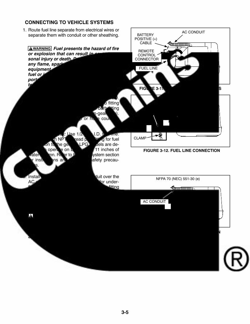
CONNECTING TO VEHICLE SYSTEMS
1. Route fuel line separate from electrical wires orseparate them with conduit or other sheathing.
WARNING Fuel presents the hazard of fireor explosion that can result in severe per-sonal injury or death. Do not smoke or allowany flame, spark, pilot light, arc-producingequipment or other ignition sources nearfuel or in the installation area. Read the im-portant safety precautions in the Fuel Sys-tems section.
2. Gasoline Fueled Sets: Connect 1/4-inch I.D.fuel hose (type SAE 30-R7) to the barb fittingon the genset. Secure fuel hose to barb fittingwith a stainless steel clamp (worm-gear type).Do not over tighten clamp or hose could bedamaged.
LPG Fueled Sets: Use 1/2-inch I.D. fuel line.Use a 1/4-inch NPTF thread pipe fitting for fuelconnection to the genset. LPG models are de-signed to operate on LP vapor at 11 inches ofwater column. Refer to the Fuel System sectionfor instructions and important safety precau-tions.
3. Install a listed 1/2-inch flexible conduit over theAC wiring. (Use water-tight conduit for under-floor mounting.) Secure the conduit to the fittingon the genset. Make sure lines do not contactsharp, hot of abrasive surfaces.
WARNING Accidental starting can causesevere personal injury or death. Do not con-nect the battery cables to the genset start-ing battery until instructed to in the InitialStart and Checks section.
FIGURE 3-11. FUEL AND ELECTRIC LINES
FIGURE 3-12. FUEL LINE CONNECTION
FIGURE 3-13. AC CONDUIT CONNECTION
AC CONDUIT
BATTERY POSITIVE (+)
CABLE
FUEL LINE
NFPA 70 (NEC) 551-30 (e)
FUELHOSE
CLAMP
AC CONDUIT
REMOTE CONTROL
CONNECTOR

3-6
4. Connect the battery positive (+) cable to thewiring harness B+ connection. Tighten the B+connection securely and cover the connectionwith the terminal boot to insulate it. Wire-tie theterminal boot in place to prevent movement ofthe boot.
5. Connect the battery negative (−) cable to anyone of the four genset mounting holes in thebase. Use star (EIT) washers on each side ofthe ring terminal when securing the terminal tobase.
6. Connect the remote control harness connectorto the mating connector on the left side of thegenset (Figure 3-16).
7. Proceed to the next section on connecting theexhaust system.
FIGURE 3-16. REMOTE CONTROLCONNECTION
FIGURE 3-15. BATTERY NEGATIVE (−)CONNECTION
REMOTE CONTROL
CONNECTOR
FIGURE 3-14. BATTERY POSITIVE (+)CONNECTION
TERMINALBOOT
BATTERY NEGATIVE (−)CONNECTION
BATTERYPOSITIVE (+)
CONNECTION

3-7
EXHAUST SYSTEMS
Use only the Onan-specified exhaust kits. Refer tothe Exhaust section for installation instructions andimportant safety precautions.
CAUTION Failure to follow the exhaust instal-lation guidelines can result in damage to equip-ment. Use the appropriate exhaust kit andinstall according to the instructions provided.
1. Connect the exhaust pipe (1-1/4-inch O.D.16-gauge aluminized or stainless steel tubingfor tailpipe, installer supplied) to the gensetwith a U-bolt clamp.
FIGURE 3-17. EXHAUST PIPE CONNECTION
EXHAUST ACCESSO-RY KIT 18 TO 25 IN (427 TO 635 mm)
EXHAUST ACCESSO-RY KIT OVER 25 IN
(635 mm)
DO NOTBEND
DO NOTBEND
EXTENDED DOWNTUBE KIT FOR
MOUNTING BELOWRAILS OR OTHEROBSTRUCTIONS

3-8
WARNING Exhaust gas presents the hazard ofsevere personal injury or death. Do not termi-nate the exhaust pipe under the vehicle. The ex-haust pipe must not terminate so that any vent,window, or opening into the living area is withinthe arc shown in Figure 3-21. Read the impor-tant safety precautions in the Exhaust Systemssection.
2. Do not terminate the exhaust tail pipe under thevehicle. The exhaust tail pipe must terminate 1inch (25.4 mm) beyond the side or end of thevehicle.
3. Support the tail pipe as close to the outside ofthe vehicle as possible.
4. Protect exhaust tail pipe from impact. Do notterminate below the clearance level of the rearaxle. Termination of the exhaust tail pipe belowthe angle of departure (lowest point on rear ofvehicle to the tire ground contact point) must beprotected by a skid bar, trailer hitch, or someframe member.
5. Be aware that any vent, window, or openingthat can be opened and that is not permanentlysealed from the vehicle living space, can be anavenue for carbon monoxide.
The tail pipe must not terminate so that anyvent, window, or opening into the living area iswithin the shaded area shown in Figure 3-21.
6. Refer to each of the sections in this manual fordetailed installation instructions and for impor-tant safety precautions. Follow the proceduresin the Initial Start and Checks section when theinstallation is complete.
LOCATE TAIL PIPEIN SHADED AREAOR ABOVE DASH
LINE
FIGURE 3-18. TAIL PIPE EXTENSION BEYONDVEHICLE
FIGURE 3-19. EXHAUST PIPE SUPPORT
FIGURE 3-21. TAIL PIPE LOCATION
FIGURE 3-20. TAIL PIPE PROTECTION
EXTEND TAIL PIPE1 IN (25.4 mm)
PAST OUTSIDE EDGE OF VEHICLE
LOCATE TAIL PIPEHANGER CLOSE TOOUTSIDE EDGE OF
VEHICLE
TAIL PIPE HANGER
ANSI 119.2 PAR. 3-4.3
ANSI 119.2 PAR. 3-4.3
ANSI 119.2 PAR. 3-4.3
OUTSIDE EDGEOF VEHICLE
OUTSIDEEDGE
SKID BAR
NO OPENINGS INTO VEHICLE’S INTERIOR,INCLUDING ENTRY DOORS, ARE ALLOWED
IN SHADED AREA.
1 IN (25.4 mm)
TAIL PIPE6 IN.
(152.4 mm)

4-1
4. Mounting
GENERAL
This genset can be mounted in a compartment or inan underfloor mounting kit. Carefully follow the ap-propriate mounting instructions. Read this manualand the exhaust kit and other applicable kit in-structions before installing the genset.
COMPARTMENT MOUNT
Compartment mount gensets are installed in aframe that is part of the vehicle. This frame must beconstructed according to safety-approved specifi-cations (see Compartment Construction section).
Unless the set will be removed from underneath thevehicle, make the access opening large enough toremove the set. Allow extra clearance for removal ofthe access cover and for spark plug removal. SeeFigure 1-1.
Minimum compartment dimensions are shown inFigure 4-1. Clearances between the genset and thecompartment are included in these dimensions.
Allow for air intake at the service side of the set andair discharge at the bottom of the set. Air inlets to theset compartment must not allow dirt, rocks, water,or slush to reach the set. Minimize dust and salt en-trance into the compartment. (See Ventilation sec-tion.)
Compartment Construction
1. Install the genset in its own compartment. Al-low a minimum of 1 inch (25.4 mm) spacing atthe front of the set and a minimum of 1/4 inch(6.4 mm) clearance on the sides, back and topof the set. See Figures 4-1 and 4-2.Allow additional front (service side) clearance ifthe vehicle air inlet is not aligned with the gen-set air inlet, to obtain the minimum free air inletof 24 in2 (155 cm2).Example: If the air inlet is along the bottomfront edge (service side) of the compartment,increase the the front clearance by one inch(25.4 mm). 24 in2 24 in (air inlet length) = 1 inchIf insulation is used to line the compartment, in-crease the compartment size to include the
width of the insulation. (Refer to the Acousticssection for insulating material specifications.)
2. If any part of the compartment is above the ve-hicle floor, separate the compartment areafrom the living quarters and fuel supply with va-por-tight walls.
3. Line the compartment walls with 26-gauge gal-vanized steel or a material of comparablestrength and fire resistance (see NFPA 70,NEC and California Title 25 for complete de-tails).
WARNING Exhaust gases present the haz-ard of severe personal injury or death. Makethe compartment walls vapor-tight to the in-terior of the vehicle to prevent exhaustfumes from entering the living quarters.
4. Construct a compartment floor that will preventoil, fuel or water accumulation. Provide open-ings in the compartment floor according to theCompartment Floor Plan, Figure 4-2.
Do not use absorbent soundproofing materialon the compartment floor. The floor shouldhave as few openings as possible, to reducethe noise level.
5. Equip the base with an oil drain hole to the out-side of the compartment. Do not mount the ex-haust pipe below the oil drain hole.
WARNING Fire presents the hazard of se-vere personal injury or death. Do not posi-tion the exhaust pipe directly below a drainhole. Hot exhaust can ignite fuel or oil.
6. Secure the genset mounting base to the sup-port frame with four 3/8-16 UNC grade 5screws. The mounting bolts must not extendmore than 1/2 inch (13 mm) into the base. SeeFigures 4-1 and 4-2. Torque 3/8 inch mountingscrews to 35 ft lbs (47 Nm).
CAUTION If the mounting base is not fas-tened securely to the vehicle compartment,road vibrations will damage the gensetcomponents. Use screws long enough forat least 1-1/2 threads to extend through theweld nut. The mounting bolts must not ex-tend more than 1/2 inch (13 mm) into thebase.

4-2
SEAL AROUND THIS AREATO THE COMPARTMENT
DOOR IF AIR INLET ISTHRU COMPARTMENT
DOOR
OUTLET
AIR INLET DIMENSIONS
REMOTE CABLECONNECTOR
(SPEC F & LATER)
REMOTE CABLECONNECTOR(SPEC A − E)
FIGURE 4-1. COMPARTMENT MOUNT OUTLINE

4-3
SEAL AROUND THIS AREA TO THECOMPARTMENT FLOOR WITH SILICON
RUBBER OR FIBERGLASS GASKET
OPTIONAL GROUND LOCATION
SEE NOTES ON PAGE 4-2
FIGURE 4-2. COMPARTMENT FLOOR PLAN

4-4
UNDER-FLOOR MOUNT
In an under-floor installation, the genset is mountedbelow the floor and outside the passenger compart-ment of the vehicle. This type of installation mustcomply with the Installation Codes and Safety Rec-ommendations (see Introduction section). Readthis section for general application information, andstudy the under-floor housing and exhaust kit in-structions for more information on under-floorinstallations.
The vehicle structure must be able to support theweight of the genset in a dynamic environment(carefully follow the important design parameters inthe instructions provided with the under-floor hous-ing kit). The vehicle manufacturer and/or the install-er must provide a structurally sound support frame,using tubing, angle brackets, or steel-reinforcedplywood or other composition board. Plywood orparticle board can be reinforced with 3-inch (76mm) or larger washers or a full metal plate.
Line the floor above the set with 26-gauge galva-nized steel or a material of comparable strength andfire resistance (see NFPA 70, NEC and CaliforniaTitle 25 for complete details).
Generator Set Location
Figure 4-3 shows the most common mountingareas for a genset. Protect the genset from road
splash and debris. If possible, drive the vehiclethrough mud and slush to test the installation.
Leave a minimum space of 1 inch (25.4 mm) be-tween the genset and the vehicle skirt for an air inlet.Provide a minimum side, back and top clearance1/4 inch (6.4 mm).
The air inlet opening to the genset compartmentmust not admit dirt, rocks, water or slush. The en-trance of dust and salt into the compartment mustbe minimized. Baffles may be needed to protectcertain areas. See the Ventilation section of thismanual for more information.
Access Opening: Provide an access opening tothe genset on the side of the vehicle. Make the ac-cess large enough for removal of the access cover.Also allow access to the oil drain and spark plug, sothe genset does not have to be removed for servic-ing these items (see Figure 1-1 for locations).
Mounting Brackets: The vehicle must be adaptedfor use with the under-floor mounting bracket kit.The construction of the vehicle must support theweight of the genset (see Specifications section). Itis the vehicle manufacturer and/or the installer’s re-sponsibility to provide carriage bolts to attach theunder-floor mounting brackets.
Review the exhaust system kit installation instruc-tions and check the components supplied in the kit.Plan clearances for removal of exhaust compo-nents when the set is removed for service.
M1718
FIGURE 4-3. COMMON GENERATOR SET MOUNTING AREAS

5-1
5. Ventilation and Acoustics
GENERAL
The most important factors of ventilation for an aircooled genset are sufficient incoming air (for com-bustion and cooling) and adequate exhausting ofheated air.
A fan draws cooling air through the inlet on the gen-erator end and pushes it across the generator andengine cooling fins. The heated air is expelledthrough the air outlet on the bottom of the set. SeeFigure 5-1.
Make certain that nothing obstructs or restricts theair intake and air outlet. Air recirculation must beminimized. If a noise or dust deflector are added tothe set, it must be located a minimum of 6 inches(150 mm) below the genset and it must be open onthree sides.
WARNING Exhaust gas presents the hazard ofsevere personal injury or death. Because dis-charged cooling air can contain deadly exhaustgas, never use discharged cooling air to heatthe vehicle.
CAUTION Operating the genset with the coverremoved can cause equipment damage. Gensetcooling air does not circulate properly with theaccess cover removed. Do not operate the gen-set with the access cover removed.
When designing the air inlet and outlet for the setcompartment (see Figures 4-1 and 4-2), allow forthe restriction of grilles and ductwork: some ex-panded metal grilles provide as little as 60 percentfree air inlet area per square foot. The most efficientgrille provides only 90 percent free inlet area persquare foot. Obtain the free inlet area of the grillematerial from the material supplier. Multiply thegrille area by the free area percentage to get thefree inlet area.
Air ducting must provide a direct free-airflow path tothe genset, with minimal bends. The duct must besmooth and non-restrictive to airflow.
Air inlet openings should be located as high as pos-sible to allow for convection cooling of heated airfrom the genset compartment after unit shutdown.Otherwise, hard starting could result from vaporlocking, hot combustion air, etc.
WARNING Fuel and fuel leakage present thehazard of fire or explosion, which can cause se-vere personal injury or death. The ventilationsystem should provide a constant flow of air toexpel any accumulation of fuel vapor. The gen-set compartment must be vapor-tight to the ve-hicle interior, to keep fumes from entering thevehicle.
Locating the free air inlet opening in the vehicle skirtor side access door is recommended. If the vehicleskirt does not extend to or below the bottom of thegenset, provide an extension.
FIGURE 5-1. COOLING AIRFLOW

5-2
ACOUSTICS
The genset is designed to minimize noise levels. Ifadditional noise reduction is required, line the topand sides of the genset compartment with a 1-inch(25.4-mm) thickness of sound absorbing material.The optional exhaust resonator can also be used tolower the noise level. Locating the air inlet awayfrom the genset air inlet opening will reduce thenoise level; however, additional compartmentspace will be required (see Compartment Mountingin the Mounting section). See the following guide-lines to construct the housing.
Make certain that all joints and corners of thecompartment are vapor-tight to the interior/ cabof the vehicle. Lining the compartment is lesseffective if openings, cracks, doors and jointsare not sealed. Seal the compartment dooredge to eliminate noise leaks around the doorperimeter.
Cover the back, top and sides of the compart-ment (not the compartment base) with fiber-glass or other self-extinguishing, sound-absor-bent material. Sound insulation and adhesiveshould be rated at 200F (90C) minimum. SeeFigure 5-2 to design the set compartment foroptimum noise reduction.
A combination of materials can reduce noisemore than a single material can. For instance, alaminate of materials of various thickness in-cluding a layer of acoustical material is more ef-fective than a single layer of acoustical materi-al.
WARNING High temperatures in thecompartment can present the hazard of fire,which can result in severe personal injuryor death. To meet ANSI and CSA tempera-ture rise requirements for vehicles, the lay-er of insulation must not reduce the mini-mum compartment size specified in Figure4-1.
SERVICE SIDEACCESS PANEL
SELF-EXTINGUISHINGACOUSTICAL MATERIAL 1/2 TO1 INCH (12.7 TO 25.4 MM THICK)
FIGURE 5-2. NOISE REDUCTION COMPARTMENT DESIGN

6-1
6. Exhaust System
GENERAL
Plan the exhaust system carefully. A proper installa-tion is vapor-tight and quiet. The exhaust system in-stallation must comply with all applicable stan-dards, local codes and regulations. Study the fol-lowing recommendations. See the instructions sup-plied with the exhaust kit for specific mounting pro-cedures.
MUFFLER RECOMMENDATIONS
The Onan-installed spark arrester muffler is U.S.Forest Service approved and meets code require-ments. Failure to provide and maintain a spark ar-rester can be a violation of the law.
Liability for damage or injury, and warranty ex-penses due to use of unapproved mufflers or in-stallation modifications becomes the responsibilityof the person installing the substitute muffler or per-forming the modifications. Contact an Onan distrib-utor for approved exhaust system parts.
EXHAUST INSTALLATION GUIDELINES
Use only Onan-specified exhaust kits. These kitshave been designed specifically for use with thisgenset. The length of pipe used in the exhaustplumbing must be tailored to each specific vehicleand is critical to the selection of the correct exhaustkit.
Exhaust kits are available for installations requiringexhaust lengths of 18 to 25 inches (457 to 635 mm)and over 25 inches (635 mm). Exhaust kits areavailable for installations with a vertical drop of up to8.5 inches (216 mm), for a deep compartment floor.See Figure 6-2.
The exhaust system must be placed no closer than3 inches (76 mm) from combustible material (wood,felt, cotton, organic fibers, etc.), or be so located, in-sulated or shielded that it does not raise the temper-ature of any combustible material more than 117F(65C) above the ambient air inlet temperature.
The exhaust system must extend a minimum 1 inch(25.4 mm) beyond the perimeter of the vehicle. Donot terminate the exhaust tailpipe under the vehicle.Be aware that any vent, window or opening that canbe opened and that is not permanently sealed fromthe vehicle living space can be an avenue for car-bon monoxide.
The tailpipe must not terminate so that any vent,window, or opening into the living area is within a sixinch (152.4 mm) radius of the tail pipe as shown inFigure 6-1.
WARNING Exhaust gas presents the hazard ofsevere personal injury or death. Do not termi-nate an exhaust pipe under the vehicle. The tail-pipe must not terminate so that any vent, win-dow, or opening into the living area is within asix inch (152.4 mm) radius of the tail pipe asshown in Figure 6-1. Keep all openings closedwhen the genset is running.
To reduce the chance of damaging the tailpipe andemitting exhaust gases under the vehicle, makecertain that no part of the exhaust system intrudesinto the departure angle or approach angle of thevehicle, unless it is protected by a skid bar or otherprotection device. The shaded areas in Figure 6-1illustrate typical mounting locations.
WARNING Exhaust gas presents the hazard ofsevere personal injury or death. Do not mountany portion of the exhaust system into the ap-proach or departure angle unless it is ade-quately protected. Use only Onan-specified ex-haust equipment with the genset. Use a suffi-cient number of hangers to prevent dislocationof the system.

6-2
TAILPIPE(RV REAR VIEW)
SKIDBARS DEPARTURE
ANGLE
AXLE LOWERCLEARANCE LINE
APPROACHANGLE
TAILPIPE
SEALEDWINDOW
NO OPENINGS INTO THE VEHICLE’S INTERIOR, INCLUDINGENTRY DOORS, ARE ALLOWED IN THE SHADE DAREA.
6 IN.(152.4 mm) TAIL PIPE
FIGURE 6-1. TAILPIPE INSTALLATION

6-3
TAILPIPE RECOMMENDATIONS
The tailpipe of the generator set will be hot dur-ing operation and can cause severe burns. Toreduce the risk of contact, concideration mustbe taken on whre the tailpipe will be located androuted.
An exhaust tailpipe is not supplied with the gensetbecause length requirements vary between vehiclemanufacturers. Refer to the following recommen-dations for information and safety considerations.
Use only the Onan-specified exhaust kits. Do not in-stall a tailpipe of less than 18 inches (457 mm) inlength. Do not extend the length of the 18 to 25 inch(457 to 635 mm) exhaust kit or vibration damage tothe exhaust system will result.
CAUTION Failure to follow the exhaust instal-lation guidelines can result in damage to equip-ment. Use the appropriate exhaust kit and in-stall it according to the instructions provided.
Tailpipes crimp onto genset exhaust, the criticaldimension would be I.D. minimum gauge of 18 .Some use 16 or 14 gauge material. Aluminized orstainless steel tubing is not required.
WARNING Exhaust gas presents the hazard ofsevere personal injury or death. Do not use flex-ible exhaust tailpipe, because it can leak orbreak from road shock or vibration. Do not ter-minate the exhaust system under the vehicle.Direct exhaust gases away from any window,door, or compartment openings. Do not operatethe genset without an exhaust tailpipe.
Use a U-bolt type automotive muffler clamp marked1-1/4 inch to connect the exhaust tailpipe to themuffler outlet. Use double rubber, U-shaped,shock-mounted hangers to support the exhaustsystem. If the tailpipe extends beyond 1 foot (304mm) from the genset, attach an automotive tailpipehanger for additional support. Also use additionalautomotive type tailpipe hangers every 2 to 3 feet(0.6 to 0.9 m) of tailpipe run. Support the exhaustsystem at or near the perimeter of the vehicle to pre-vent the pipe from being damaged and pushed upunder the vehicle skirt. Attach hangers to steelframework, not wood or other floor materials. Referto Figure 6-2 for typical tailpipe installations.
CAUTION Angular mounting of muffler andtailpipe hanger brackets can result in exhaustsystem damage. Properly mounted hangerbrackets will absorb much road shock vibrationand prolong the use of exhaust system compo-nents. Mount muffler and tailpipe hanger brack-ets directly above the component being sup-ported, not at an angle. Do not twist the rubbersections of any hangers.
CAUTION Excessive exhaust back pressurecan cause engine damage. If a tailpipe deflectoris used, make sure it is large enough to preventback pressure.
CAUTION Water vapor can cause engine dam-age. Do not connect the genset exhaust to thevehicle exhaust system, because water vaporfrom one engine can damage the other.

6-4
EXHAUST ACCESSORY KIT18 TO 25 IN. (457 TO 635 mm)
EXHAUST ACCESSORY KITOVER 25 IN. (635 mm)
EXTENDED DOWN TUBE KITS8.5 IN. OVER 25 IN. (635 mm)
HANGERBRACKET
HANGERBRACKET
TAILPIPE NOTFURNISHED BY ONAN
TAILPIPE NOTFURNISHED BY ONAN
HANGER BRACKET, IFREQUIRED DUE TO
LENGTH OF TAILPIPE
HANGER BRACKET, IFREQUIRED DUE TO
LENGTH OF TAILPIPE
HANGERBRACKET
DO NOT BEND OR TWISTFLEXIBLE SECTION
DO NOT BEND ORTWIST FLEXIBLE
SECTION
DO NOT BEND ORTWIST FLEXIBLE
SECTION
HANGER BRACKET, IFREQUIRED DUE TO
LENGTH OF TAILPIPE
FIGURE 6-2. EXHAUST SYSTEM EXAMPLES FOR COMPARTMENT MOUNT INSTALLATIONS

7-1
7. Fuel System
GENERAL
This section describes fuel system installations forrecreational vehicles and travel trailers.
WARNING Fuel presents the hazard of fire orexplosion that can result in severe personal in-jury or death. Do not smoke or allow any flame,spark, pilot light, arc-producing equipment orother ignition sources around fuel or fuel com-ponents, or in the installation area. Keep a typeABC fire extinguisher nearby. The ventilationsystem must provide a constant flow of air toexpel any accumulation of fuel vapor while thevehicle is in transit. Compartments must be va-por-tight to the vehicle interior to prevent anyfumes from entering these areas.
WARNING Gasoline and LPG fuel may be acci-dentally ignited by electrical sparks, presentingthe hazard of fire or explosion, which can resultin severe personal injury or death. For this rea-son, when installing the genset:
Do not tie electrical wiring to fuel lines.
Do not run electrical lines and fuel linesthrough the same compartment openings.
Keep electrical and fuel lines as far apart aspossible.
Place a physical barrier between fuel linesand electrical lines wherever possible.
If electrical and fuel lines must passthrough the same compartment opening,make certain that they are physically sepa-rated by running them through individual
channels, or by passing each line through aseparate piece of tubing.
GASOLINE FUEL SYSTEM
Fuel System Provisions
The genset fuel pump has an integral fuel shutoffvalve as a safety feature. If the vehicle fuel tank be-comes pressurized (3 psi maximum), the positivefuel shutoff prevents the genset from being floodedwhen the genset is not running. The vehicle fueltank gas cap should relieve pressure at 1-1/2 psi.
Travel trailer installations can use an optional re-mote fuel tank to supply fuel to the genset. See Re-mote Fuel Tank section.
Onan recommends installing an in-line manual fuelshutoff valve, to close the fuel line when the set isremoved for service.
Recommended Fuel
See the Operator’s Manual for fuel recommenda-tions.
WARNING Fuel presents the hazard of fire orexplosion that can cause severe personal injuryor death. Never fill the fuel tank when the engineis hot or is running. Do not permit any flame,spark, pilot light, cigarette or other ignitionsource near the fuel system.
Fuel Consumption
Genset fuel consumption varies proportionately tothe amount of electrical load. Refer to the Specifica-tions section for approximate fuel consumption atno load, half load, and full load.

7-2
Fuel Line Installation
Mounted Fuel Tank: Vehicle fuel systems operateat a specified fuel pressure. For this reason, do notchange or remove the fuel fill tube, fill limiter vent,vapor canister, vapor lines, filler cap or any part ofthe fuel system without the approval of the vehiclemanufacturer. Check the filler cap to make sure thatthe pressure vacuum relief valve functions properlyat 1-1/2 psi: replace it if it is defective.
Do not tie the genset fuel line into the vehiclefuel supply line. Unauthorized fuel system modifi-cations can cause dangerous operating conditions.
Tying a genset fuel line into a vacuum supplyline (vehicle fuel pump at the engine) cancause the genset to starve for fuel at highwayspeeds or during acceleration.
Tying a genset fuel line into a pressure supplyline (vehicle fuel pump in the fuel tank) cancause poor genset operation and create a haz-ard of fire or explosion caused by fuel leakage.
Some vehicle manufacturers permit tying into thefuel return line on high pressure fuel systems. Con-tact the vehicle manufacturer for details and ap-proval. The fuel return line pressure at the point ofconnection must not exceed 1-1/2 psi, or carburetorflooding could result.
If a separate connection is not supplied for the gen-set, add a second fuel pickup in the tank. This pick-up should not extend below the bottom 1/4 of thetank, so the vehicle will run after the genset runs outof fuel.
WARNING Gasoline presents the hazard of ex-plosion or fire, which can result in severe per-sonal injury or death. Do not connect the gensetfuel line to the pressurized part of the vehiclefuel system. Flooding of the genset compart-ment can occur, resulting in a fire hazard.
SC1463-9s
FUELLINE
CLAMP
BARB FITTING
FIGURE 7-1. GASOLINE FUEL LINE CONNECTION
CAUTION Connecting the genset fuel line witha tee to the main fuel line can result in the gensetstarving for fuel when the vehicle is operated athighway speeds. The genset fuel pump doesnot have the power to overcome the draw of thevehicle engine fuel pump. For this reason, use aseparate fuel line to the genset, or use a sepa-rate fuel tank.Connect a 1/4-inch I.D. fuel hose (type SAE 30-R7)to the barb fitting on the genset (Figure 7-1). Securefuel hose to barb fitting with a stainless steel clamp(worm-gear type). Do not over tighten clamp or thehose could be damaged. The fuel hose must belong enough to allow genset movement, and pre-vent binding, stretching or breaking.
Onan recommends copper or hot dip coated seam-less steel tubing (conforming to ASTM A-254) anddouble flared connections for long runs between thefuel tank and the flexible connector to the genset.
Run the fuel line at the same height as the top of thefuel tank (or above the tank) to a point as close to thegenset as possible. This reduces the danger of fuelsiphoning out of the tank if the line should break.The maximum fuel pump lift of the genset is 3 feet(0.91m).
Keep fuel lines away from hot engine or exhaustareas, to reduce the chance of vapor lock.
Fuel lines should be accessible and protected fromdamage. Use metal straps without sharp edges tosecure fuel lines. Do not run fuel lines where theymay contact sharp or rough surfaces, or where theymay be kinked, pinched, chaffed, or struck. If fuellines enter vehicle interior, seal openings aroundthe line to prevent entry of exhaust fumes.

7-3
Remote Fuel Tank: A remote fuel tank can be usedin travel trailer and other special installations. Fillthe tank with the recommended fuel and connectthe genset fuel line to the tank using quick discon-nect fittings. Route the fuel line away from any hotexhaust system components, moving parts, sharpor abrasive surfaces, and road hazards. Do not lo-cate the fuel supply more than 3 feet (914 mm) be-low the genset to prevent exceeding the fuel pumplift capacity.
Observe all applicable codes and regulations forstorage, transporting and handling of remote fueltanks. The fuel tank must be installed in its owncompartment. The compartment must be vaportight from the interior of the vehicle and the compart-ment must be fire resistant. See Figure 7-2 for mini-mum compartment dimensions for the optionalOnan remote fuel tank.
The compartment must be vented to prevent the ac-cumulation of fuel fumes. Provide a vented bottomin the compartment and provide a minimum of 6 sq.in. (387 sq. mm) of opening in the top of the accessdoor.
The fuel system must be designed so that fuel leak-age could not contact electrical or exhaust systemcomponents. Maintain at least 6 inches (152 mm)clearance between the fuel system and any un-shielded exhaust system component.
The fuel tank must be securely fastened inside thecompartment. Mounting straps can be used to se-cure the tank.
WARNING Fuel presents the hazard of fire orexplosion that can cause severe personal injuryor death. Do not store or transport a remote fueltank inside a vehicle. Observe all applicablecodes and regulations for storage, transport-ing, and handling of remote fuel tanks.
ACCESS DOOR
VENT OPENING 6 SQ. IN. (387 SQ. mm) LOUVERS OR SCREEN
OPEN BOTTOM EXCEPTFOR TANK SUPPORTS
REMOTE FUEL TANK
METAL LINED ANDSEALED TO SIDEWALL
AND INSIDE OF VEHICLE
FIGURE 7-2. TYPICAL REMOTE FUEL TANK COMPARTMENT

7-4
EVAPORATIVE SYSTEM INSTALLATION
These instructions cover installation of the genera-tor set fuel evaporative system provided for com-pliance with the California code of regulations forsmall off-road equipment effective January 1, 2008and Federal Small SI regulation effective January 1,2011.
For safety and compliance, the installation must bein accordance with these instructions.
The instructions apply to the following generator setmodel:
2.8LVFA6050
Completing the installation of the genset evapora-tive fuel system is required for all towable or similargenerator set applications where on−board gaso-line fuel storage is self−contained in the trailerequipment.
It is the responsibility of the towable equipmentmanufacturer OEM to complete the installation ofthe evaporative fuel system exactly as specified inthe CARB EO & EPA certification for the CumminsOnan product being installed. These requirementsare detailed in the procedure below. Any deviationsfrom this installation procedure will forfeit the emis-sion certification on the fuel system and transfer en-gine evaporative emission certification responsibil-ity to the trailer equipment manufacturer/OEM perCFR 40 Part 1060.
If purchasing a complete or partial fuel system kit orcomponents from a third party fuel systemmanufacturer, the requirements of this Cumminsinstallation manual shall be met and the systemmust be verified by the OEM & fuel system supplieras meeting these requirements before completingthe installation.
Any construction deviations from these assemblyrequirements would invalidate the evaporative cer-tification per CFR 40 Part 1060 & Article 1, Chapter9, Division 3 Title 13 sections 2400 through 2773and the towable equipment OEM would then be re-sponsible for recertification of the fuel system withCalifornia Air Resources Board and US EPA.
Any questions regarding these installation instruc-tions or evaporative emission certification should
be directed to Cummins Power Generation for clari-fication.
System Components
The evaporative system consists of the fuel tank,carbon canister, generator set and connectinghoses. Gasoline vapors in the fuel tank accumulatein the carbon canister from which they are drawninto the engine combustion chamber and burnedwhile the generator set is operating.
Fuel Tank
Note: The following specifications apply only toevaporative emissions performance. The installer isalso responsible for the selection and installation ofthe fuel tank to meet other safety and performancerequirements that may be applicable.
For compliance with evaporative emissions regula-tions, the fuel tank shall:
1. Be metal.
2. Have a 6 to 35 gallon capacity.
3. Have a permanently tethered cap.
4. Have cap that provides a vapor seal and thataudibly signals that the vapor seal has been es-tablished.
5. Have a roll-over vent valve with connection for5/16 inch ID hose. This hose connects to thecarbon canister.
6. Have a fill-neck and an anti-spit-back valve if itis a non top-fill tank.
7. Be constructed to meet the requirements ofSection 393.67 (joints, fittings and threads) ofthe Federal Motor Carrier Safety Administra-tion Regulations.
8. Have connections that meet the requirementsof the following SAE standards, when applica-ble: J1231 (Formed Tube Ends for Hose Con-nections and Hose Fittings), J1508 (HoseClamp Specifications), J2260 (NonmetallicFuel System Tubing with One or More Layers),J2044 (Quick Connector Specification for Liq-uid Fuel and Vapor/Emissions Systems), andJ2599 (Fuel Filler Pipe Assembly Design Prac-tice to Meet Low Evaporative Emission Re-quirements).

7-5
Carbon Canister
Use a Delphi carbon canister shown below. No oth-er carbon canisters are acceptable.
PartNumber
Description
17208276 2.1L, 130g working capacity, 24.5gallon max
17208238 3.1L, 196.5g working capacity
17208262 3.3L, 233.8g working capacity
Mount the canister in an acceptable orientation(Figure 7-3) in accordance with its instructions.
Connect the 5/16 inch hose barb (identified by thefuel pump icon) to the hose from the fuel tank andthe adjacent 3/8 inch hose barb to the hose from thegenerator set. See Figure 7-4.
Note: Use 5/16 inch hose for vapor lines. Use anSAE J2044 quick connect fuel fitting on the canisterhose barb or use a soap-free lubricant such as WD40to slip the hoses on the canister hose barbs. Securethe hoses with Oeitiker� ear-type clamps or equiva-lent.
To prevent dirt from entering the canister vent whenit is mounted in a “dirty” location, connect the5/8 inch hose barb to a hose terminated outside theliving space of the vehicle at a location that is not ex-posed to road splash or dust. Alternatively, secureOnan Part Number 0148-1343 vent filter to the hosebarb.
CAUTION Blockage of the canister vent orvent hose could lead to collapse of system com-ponents due to vacuum.
WARNING Do not vent the canister into the ve-hicle or other confined space where the vaporscould accumulate to a flammable level.
FIGURE 7-3. ACCEPTABLE CANISTER MOUNTING ORIENTATIONS

7-6
Generator Set
Connect the 5/16 inch generator set hose barb tothe vapor purge hose from the carbon canister.Connect the 1/4 inch hose barb to the fuel supplyhose from the fuel tank. See Figure 7-4.
Gasoline Hoses
The fuel hoses used inside the generator set arelow permeation fuel hoses which meet Federal andCalifornia standards for gasoline evaporative emis-sions.
The vapor and liquid hoses connecting the fuel tankto the generator set, the fuel tank to the carbon can-ister and the carbon canister to the generator setmust also be low permeation fuel hoses. Low per-meation fuel hose is required to meet these require-ments for gasoline generator sets sold in or used forcommerce in the State of California. The followinghose materials are acceptable:
Avon Automotive “Greenbar” (EO# G-05-018)SAE J30R7
Avon Automotive “Greenbar 1200”(EO# C-U-05-009) SAE J30R12
Gates 4219D (EO# C-U-06-002) SAE J30R9
Gates Barricade (EO# Q−09−019)
Kubota (EO# C-U-05-003) SAE J30R7
Mark IV Automotive “Gen 2” (EO# C-U-05-002)SAE J30R7
Mark IV Automotive “Fluoroperm” (EO# C-U-07-017) SAE J30R9
Mark IV Automotive “Dayperm” (EO#C-U-06-030) SAE J30R7
Mark IV Automotive “Dayperm” (EO#G−05−016)
Mold-Ex Division of SETi, Inc. “SETiFLEX II”(EO# G-05-17A) SAE J30R7
Parker Hannifin Corp “Super Flex FL−7 series389XX” (EO# Q−08−013)
Veyance Technologies Inc. “Goodyear Flex-shield” (EO# Q−09−022)
Lubricants used when connecting fuel hoses canleave residues that can clog fuel jets. Only use“soap-free” lubricants such as WD40.
CAUTION When connecting fuel hoses, onlyuse soap-free lubricants such as WD40, whichruns through with the fuel without leaving resi-dues that can clog fuel jets.

7-7
GENERATORSET
FUEL TANK
CARBONCANISTER
1/4 INCHPURGE HOSE
(VAPOR)
5/16 INCHPURGE HOSE
(VAPOR)
1/4 INCH FUELLINE (LIQUID)
5/8 INCH VENT HOSE TO CLEAN OUT-SIDE AIR SPACE OR PN 0148-1343 VENT
FILTER
FIGURE 7-4. EVAPORATIVE SYSTEM COMPONENTS

7-8
LPG FUEL SYSTEM
Fuel System Provisions
LPG models are designed for a low-pressure vapor-withdrawal type of LPG supply system. See Figure7-5. LPG supply pressure at the inlet to the demandregulator must be 9 to 13 inches (229 to 330 mm)water column (WC) when the genset is running un-der full load.
WARNING LPG fuel presents the hazard of ex-plosion or fire that can result in severe personalinjury or death. Do not connect the genset fuelline directly to the LPG fuel cylinder or fuel leak-age could result from excessive fuel inlet pres-sure. A regulator must be used between thegenset and the fuel cylinder that reduces supplypressure to 9 to 13 inches (229 to 330 mm) watercolumn.
LPG set operation is highly sensitive to variations inaltitude, temperature, and fuel BTU content. Forthis reason, the fuel system may need to be ad-justed after installation. Refer to the Service Manualif adjustments are required.
Recommended Fuel
See the Operator’s Manual for fuel recommenda-tions.
Fuel Consumption
Genset fuel consumption varies proportionately toamount of electrical load. Refer to the Specifica-tions section for approximate fuel consumption atno load, half load, and full load.
Propane Fuel Lines and Supply Tank
WARNING LPG fuel presents the hazard of fireor explosion that can cause severe personal in-jury or death. Do not permit any flame, spark,arcing switch or equipment, pilot light, ciga-rette, or other ignition source near the fuel sys-tem. Keep an ABC type fire extinguisher nearby.
Review each of the codes that apply to LPG gensetinstallation. Paragraph 2-11 (LP-Gas Engine Fuel
installations) of NFPA Pamphlet 501C and para-graph 3-6.2.5 of NFPA 58 (piping hose and fittings).These sections deal with fuel tanks and lines, butdoes not cover all applicable codes and regulations.Obtain this information by writing to the addresslisted in the beginning of this manual.
For a long fuel line run, use seamless steel tubingwith flared ends. Make flexible hose connections atthe fuel tank and at the genset. Use 3/8-inch I.D. fuelline for runs up to 5 feet (1.5 m) long provided that, inaddition, no more than 20 feet (6.1 m) of pipe or tub-ing with an I.D. of at least 5/8-inch is used. Use1/2-inch I.D. fuel lines for runs up to 15 feet (4.6 m).
Mount a manual shutoff valve on the fuel supplytank. When installing the fuel lines, keep these fac-tors in mind:
Install LPG fuel lines to be accessible, but pro-tected from damage.
Use metal straps without sharp edges to se-cure fuel lines.
Keep fuel lines away from hot engine or ex-haust.
Do not run fuel lines next to electrical wiring.
Do not connect the genset fuel supply line to any ap-pliance fuel supply line. The genset can draw fuelaway from other appliances and cause a flame out.To prevent the possibility of flameout, the fuel sup-ply system must be designed to deliver sufficientfuel for normal operation of the genset and other ap-pliances at the expected temperature conditions. Itmay be necessary to use a separate fuel tank for thegenset if sufficient fuel cannot be supplied with asingle tank system.
WARNING LPG fuel presents the hazard of ex-plosion or fire which can result in severe per-sonal injury or death. If flameout occurs with anunvented appliance, LP gas can accumulate in-side the vehicle and create a safety hazard. Donot connect the genset fuel supply line to an LPgas supply line that is supplying another ap-pliance.

7-9
Testing Fuel System for Leaks
Before operating the set, test the LPG fuel systemfor leaks. Testing must conform to procedures listedin NFPA-58, or to the UL recommended test proce-dure, as follows:
After assembly and before initial operation, all fuelsystem connections, hose, valves, regulators, andfittings must be tested and proven free of leaks us-ing a soap-and-water (or equivalent) solution while
the system is under gas or air pressure of at least 90psi (620 kPa).
WARNING LP gas (Propane) presents the haz-ard of fire or explosion that can cause severepersonal injury or death. Do not permit anyflame, spark, pilot light, cigarette, or other igni-tion source near the fuel system. Keep an ABCtype fire extinguisher nearby.
Other approved methods of detecting leaks may beused if appropriate. This test must not be made witha flame.
LPGCARBURETOR
TWO STAGEREGULATOR
VAPORSHUTOFF
VALVE
11 INCHES W.C.OUTLET PRESSURE
DEMANDREGULATOR
FUEL SHUTOFFSOLENOID
3/8- OR 1/2-INCHI.D. FUEL LINE
(SEE TEXT)
ADAPTER FOR 3/8-OR 1/2-INCH I.D.LINE TO 1/4-INCH
NPTF FITTING(SEE TEXT)
FIGURE 7-5. TYPICAL LPG VAPOR WITHDRAWAL FUEL SYSTEM

7-10
THIS PAGE IS INTENTIONALLY LEFT BLANK

8-1
8. Electrical Connections
General
WARNING HAZARDOUS VOLTAGE! Touchinguninsulated live parts inside the generator setand connected equipment can result in severepersonal injury or death. For your protection,stand on a dry wooden platform or rubber insu-lating mat, make sure your clothing, and shoesare dry, remove jewelry from your hands anduse tools with insulated handles. Secure pro-tective covers when completing installation.
WARNING IMPROPER WIRING can cause fireor electric shock resulting in severe personalinjury or death.
This section covers installing the genset electricalsystem for:
Connecting the load
Connecting a remote control (if used)
Connecting the genset starting battery
Connect the battery last, to avoid accidentally start-ing or short-circuiting the set during installation.Connect the positive (+) battery cable first and thenegative (−) battery cable last to reduce the risk ofarcing.
WARNING Accidentally starting the gensetduring installation can cause severe personalinjury or death. Do not connect the starting bat-tery until instructed to do so in the Initial Startsand Checks section.
The wiring must meet all applicable electricalcodes. For this reason, a qualified electricianshould install and inspect the wiring.
Mount switches and controls securely, to preventdamage from vibration and road shocks. Allswitches must be vibration-proof to prevent acci-dental opening or closing while the vehicle is in mo-tion.
AC Wiring
Wire Types
The leads attached to the genset output must havea current rating of not less than 115 percent of the
nameplate current rating of the genset. The Onan-supplied AC feeder conductor insulation is rated at125C. Wires connected to the Onan feeder con-ductors must either meet this insulation rating, or bea larger size (see National Electrical Code, NFPA70).
Use stranded wire for all load connections. Loadwiring must be appropriately sized and insulated forthe specified current rating. Grounding must com-ply with all codes.
Conduit
Install the generator load conductors in a flexiblemetallic conduit. Cut the conduit to length, leavingextra wire for the junction box connections. Con-necting wires must be correctly sized and insulatedfor the current rating. Round off or cover the ends ofthe conduit, to prevent its sharp edges from cuttingthe insulation.
Use waterproof conduit in applications where theconduit will be exposed to the elements. Run theconduit so that it does not interfere with the move-ment of the genset.
To reposition the 90 conduit fitting, loosen the lock-ing nut (toothed ring), turn fitting counterclockwiseto desired location, and tighten locking nut.
Seal all openings made for conduit, so exhaust orfuel vapor cannot enter the living quarters. Flexiblemetal conduit must be sealed internally at the endwhere it terminates inside the junction box or panelboard (flexible conduit is not vapor-tight along itslength).
WARNING Exhaust gas and fuel fumes presentthe hazard of severe personal injury or death. Toprevent exhaust gas and fuel fumes from enter-ing the vehicle interior, seal all openings madefor conduit, wiring, etc. Also seal the wiringwithin the conduit itself. Use only a silicone/rub-ber based sealant.

8-2
Wiring Disconnect Method
There must be no chance that an outside powersource be connected to the generator set. Feed-er conductors from the set compartment must ter-minate in a 120-volt double-pole, double-throw,positive-off switching device mounted ahead of thevehicle distribution panel; or they must connect to agenset receptacle box. Figures 8-1 and 8-2 showexamples of the wire connection.
Line Circuit Breaker
The genset has a line circuit breaker mounted onthe side of the control panel. The breaker providesshort circuit and overload protection for the genera-tor.
Load Connections
The generator output voltage and maximum currentrating are specified on the genset nameplate.
Load wiring must be appropriately sized and insu-lated for the specified current rating. Grounding pro-cedures must comply with codes.
A lead to be connected to an output feeder conduc-tor shall not be more than two AWG sizes smallerthan the output lead conductor and the insulationshall be:
Rubber (with braid), neoprene, or thermoplas-tic, with a wall thickness of at least 0.030 inch(0.76 mm).
Other material having the same or better elec-trical and mechanical properties.
WARNING Electrical shock can cause severepersonal injury or death. Use only approvedpower supply assemblies. Never remove thegrounding pin from assemblies. Incorrectground or no ground can cause the vehicle tobecome electrically “hot”. Equip the vehiclewith adequate Ground-Fault Circuit Protectiondevices to meet the National Electrical Code(NFPA 70, 551-9 C) and for personal safety.
WARNING Gasoline fuel presents the hazardof fire or explosion, which can result in severepersonal injury or death. Do not tie electricalwiring to fuel lines.
WARNING Gasoline and LPG fuel may be acci-dentally ignited by electrical sparks, presentingthe hazard of fire or explosion, which can resultin severe personal injury or death. For this rea-son, when installing the genset:
Do not tie electrical wiring to fuel lines.
Do not run electrical lines and fuel linesthrough the same compartment openings.
Keep electrical and fuel lines as far apart aspossible.
Place a physical barrier between fuel linesand electrical lines wherever possible.
If electrical and fuel lines must passthrough the same compartment opening,make certain that they are physically sepa-rated by running them through individualchannels, or by passing each line through aseparate piece of tubing.

8-3
REMOTE CONTROL
CONNECTOR
FLEXIBLECONDUIT
JUNCTIONBOX VEHICLE WIRING
DOUBLE POLEDOUBLE THROW
SWITCHINGDEVICE
POWER SUPPLY CORD
MAINBREAKER
HACRBREAKERFOR AIR
CONDITIONER
GFCI*BREAKER
*IMPORTANT!GROUND-FAULT CIRCUIT INTERRUPTERS(GFCIs) ARE REQUIRED BY THE NATION-AL ELECTRICAL CODE (NFPA 70, 551-7(C)IN ALL EXTERNAL AND SOME INTERNALOUTLETS. TO PROPERLY EQUIP YOURRECREATIONAL VEHICLE WITH THESE
PROTECTION DEVICES, CONTACT YOURRV MANUFACTURER OR DEALER FOR
RECOMMENDATIONS.
VEHICLE ACDISTRIBUTION
PANEL
B+
TO VEHICLE AC
BLACK
WHITE
GREEN
DISTRIBUTION PANEL
TRANSFER SWITCH120V
N
L1
UT
ILIT
Y S
UP
PLY
CO
RD
GND
120V
L1 NGND
GENSET
SCHEMATIC
FIGURE 8-1. SWITCHING DEVICE WIRING FOR UTILITY POWER

8-4
REMOTE CONTROL
CONNECTOR
*IMPORTANT!GROUND-FAULT CIRCUIT INTERRUPTERS(GFCIs) ARE REQUIRED BY THE NATION-AL ELECTRICAL CODE (NFPA 70, 551-7(C)IN ALL EXTERNAL AND SOME INTERNALOUTLETS. TO PROPERLY EQUIP YOURRECREATIONAL VEHICLE WITH THESE
PROTECTION DEVICES, CONTACT YOURRV MANUFACTURER OR DEALER FOR
RECOMMENDATIONS.
FLEXIBLECONDUIT
JUNCTIONBOX
B+
VEHICLE WIRING
DISCONNECTING DEVICE
POWER SUPPLYCORD
MAINBREAKER
HACRBREAKER FOR
AIRCONDITIONER
GFCI*BREAKERS
BLACK
WHITE
GREEN
120V
N
L1
GND
120V
L1
GND
GENSET
SCHEMATIC
GENSET
UTILILITY
N
POWER SUPPLY CORDTO DISTRIBUTION PANEL
CONNECT TO UTILITYOR GENSET
PLU
G
RE
CE
PTA
CLE
RE
CE
PTA
CLE 120V
FIGURE 8-2. UTILITY POWER CORD FOR SWITCHING

8-5
DC Wiring
These sets have a 12 VDC, negative-ground en-gine control and cranking system.
Remote Control (Option)
Onan offers optional remote control kits that can beconnected to the genset. There are three modelsavailable:
Remote panel with start/stop switch and indica-tor lamp only (see Figure 8-3).
Remote panel with start/stop switch, indicatorlamp, and hour (elapsed time) meter (see Fig-ure 8-4).
Remote panel with start/stop switch, indicatorlamp, and battery DC voltmeter (see Figure8-5).
The location of the remote control panel can vary byapplication. Refer to the instructions supplied withthe remote control kit for more installation informa-tion and important safety precautions.
Be sure to seal all openings made for wiring so ex-haust or fuel vapors cannot enter the living quarters.If flexible metal conduit is used, it must be sealed in-ternally at the end where it terminates. Flexible met-al conduit is not vapor-tight along its length due to itsconstruction.
WARNING Inhalation of exhaust gas or ignitionof fuel vapor can cause severe personal injuryor death. Be sure to vapor-seal flexible metalconduit and all openings made during installa-tion of the genset with a silicone/rubber basedsealant.
A remote control connector is located on a pigtaillead on the outside of the genset (see Figure 8-6).Contact an Onan dealer for the proper remote con-nector plug and wiring harness assembly.
INDICATORLAMP
START/STOPSWITCH
FIGURE 8-3. REMOTE PANEL WITH START/STOPSWITCH ONLY
INDICATORLAMP
START/STOPSWITCH
HOURMETER
FIGURE 8-4. REMOTE PANEL WITH START/STOPSWITCH AND HOUR METER
INDICATORLAMP
START/STOPSWITCH
BATTERY DCVOLTMETER
FIGURE 8-5. REMOTE PANEL WITH START/STOPSWITCH AND DC VOLTMETER
For non-Onan remote control panels, refer to Figure8-7 for a typical remote control wiring diagram. Theconnector which mates with the genset connectorcan be ordered from Onan. Refer to the Onan Ac-cessory Catalog.

8-6
BATTERIES
To prevent accidental starting of the genset duringinstallation, do not connect the battery cables at thebattery until so instructed in the Initial Start andChecks section.
WARNING Accidental starting of the gensetcan can cause severe personal injury or death.Do not connect the starting battery until soinstructed in the Initial Start and Checks sec-tion.
Onan does not recommend that the vehicle startingbattery be used to operate the genset. Doing thiscan discharge the battery under some operatingconditions.
SC1463-10s
REMOTE CONTROL
CONNECTOR
FIGURE 8-6. REMOTE CONTROL CONNECTOR
+
−
+
−
CONTROL PANEL CONNECTOR(USER SUPPLIED)CONTROL PANEL
START
GND
SWITCHED B+
STOP
START/STOP SWITCH
DC VOLTMETER
DC
VOLTMETER
+
−
HOUR
METER
HOUR METER
OP
TIO
NA
LO
PT
ION
AL
ABC
F
GENSETCONNECTOR
EF
GHW
IRE
EN
D
CO
NN
EC
TO
R E
ND
WIR
E E
ND
CO
NN
EC
TO
R E
ND
A
B
C
D E
F
G
H
A
A
B
B
WIRE END
(VIEW B−B)
CONNECTOR END
(VIEW A−A)
LED
FIGURE 8-7. TYPICAL REMOTE CONTROL WIRING DIAGRAM

8-7
Battery Capacity
The genset has a 12 VDC, negative-ground controland starting system. See Table 8-1 for minimumbattery capacity requirements.
TABLE 8-1. COLD CRANKING AMPS FORMINIMUM 12-VOLT BATTERY
ABOVE 32 F BELOW 32 F(0 C) (0 C)
360 Cold Cranking 450 Cold CrankingAmps Amps
(Approx. 70 amp/hour) (Approx. 95 amp/hour)
Battery Compartment
Mount the battery in its own compartment, awayfrom the genset and any spark-producing device.For ventilation, provide the battery compartmentwith an opening of at least 1.7 in2 (11 cm2) at the topand 1.7 in2 (11 cm2) at the bottom.
Mount the battery on a rigid support structure,where leaks and accidental spills cannot damagethe genset, fuel lines, and wiring.
WARNING Batteries present the hazard of ex-plosion, which can result in severe personal in-jury. Because batteries give off explosive gas,install the battery in a separate compartmentfrom the genset and away from all flames, pilotlight, arcing, or spark-producing devices.
Battery Cables
Because of the high cranking currents involved, it ishighly recommended that a negative (−) batterycable be run with the positive (+) battery cable be-tween the battery and the genset. Size the cablesaccording to Table 8-2. Total cable length is thesum of the lengths of the positive (+) and negative(−) cables. In other words, total cable length will beapproximately twice the distance between the bat-tery and the genset.
Alternatively, use rated cranking current as the ba-sis for calculating battery cable size. Rated crank-ing current for these gensets is 180 amperes at 0�F(−18�C). The cables should be sized so that voltageacross the cranking motor terminals will be within 1volt of the voltage across the battery terminals.
WARNING Batteries present the hazard of ex-plosion, which can result in severe personal in-jury. Because batteries give off explosive gas,always disconnect the negative (−) cable first,and connect it last to reduce the risk of arcing.
TABLE 8-2. CABLES FOR COLD WEATHERSTARTING TO −20F (−29C)
*CABLE LENGTH CABLEIN FEET (METERS) SIZE
0 to 45 (0 to13.7) 2**46 to 60(14 to18.3) 0
61 to 80(18.6 to 24.4 00
* Battery cable lengths are total lengths from thebattery to the generator back to the battery andwhen using a toatal of 1000CCA (Cold Crank-ing Amps).
** #2 cable is acceptable up to 20 feet (6.1 m) ifthe battery capacity exceeds 1000 CCA.
Negative (−) Battery Connection. Connect oneend of the negative (−) battery cable to the gensetground. Tighten the ground connection securely(see Figure 8-8).
Alternate Negative (−) Battery Connection. Incases where the distance from the battery to thegenset is quite long, the vehicle frame (ground) canbe used for the return cranking current:
1. Connect one end of a short, negative (−) bat-tery cable (of the same size as the positive (+)battery cable) to the vehicle frame near the bat-tery. (Do not connect the other end to the bat-tery at this time.)
2. Connect one end of a short, negative (−) bat-tery cable (of the same size as the positive (+)battery cable) to the vehicle frame near thegenset. Connect the other end to the gensetground. See Figure 8-8.
NOTE: Make sure that the frame (ground) connec-tions (to major frame members, if possible) are se-cure enough to minimize electrical resistance. Avoidmaking these connections at welds or mechanicaljoints.

8-8
Positive (+) Battery Connection. Refer to Figure8-8 for the following steps:
1. Connect the positive (+) battery cable to thering on the genset B+ cable ring.
2. Tighten this connection securely.
3. Slide the terminal boot on the genset B+ leadover the connection.
4. Use a tie wrap to hold the terminal boot in placeover the connection.
Route battery cables away from fuel lines and hotengine exhaust components. Battery cable should
be accessible for inspection and replacement, pro-tected from damage and secured to prevent chafingdue to vibration.
WARNING Routing battery cables with fuellines can lead to fire and severe personal injuryor death. Keep battery cables away from fuellines.
CAUTION Failure to secure the battery cableterminals can result in personal injury and/orequipment damage from an electrical short. Seethat terminal connections are secure. If neces-sary, secure cables to prevent abrasion.
Genset Bonding Terminal
The genset ground, as shown in Figure 8-8, is alsothe bonding terminal for grounding the genset to thevehicle frame (ground) when a continuous negative(−) battery cable is used from the battery directly tothe genset. Connect an 8 AWG grounding wire fromthe vehicle frame to the genset ground.
NOTE: Make sure that the frame (ground) connec-tions (to major frame members, if possible) are se-cure enough to minimize electrical resistance. Avoidmaking these connections at welds or mechanicaljoints.
WARNING Failure to ground the genset prop-erly can result in injury or death. The gensetmust be grounded to the vehicle frame.
BATTERY NEGATIVE (−)CONNECTION
RING TERMINALBATTERY POSITIVE (+)
CONNECTION
TERMINAL BOOT
FIGURE 8-8. BATTERY CABLE CONNECTIONS

9-1
9. Initial Start and Checks
INSTALLATION REVIEW
Prior to initial start up of the genset, check () each of the following items. For a safe and effective installation,each answer must be yes: if not, that aspect of the installation should be reworked or provision made to satisfythe requirement.
� If installed in a compartment, is the compartment metal-lined and sealed around all edges?
� Are wiring holes into the inside of coach (including the inside of AC conduit) sealed to prevent passage ofexhaust gases?
� Can the following routine maintenance items be performed through the service access panel? Refer toFigure 3-3.� Change oil� Adjust carburetor � Start/stop the unit � Change air filter � Governor adjustment � Operate AC circuit breaker � Change spark plug
� Are air inlet and exhaust openings clear and sufficiently sized (see Mounting section) for proper airflow?
� If the installation is for an under-floor kit, is there a metal barrier between the genset and a combustiblefloor? See Figure 3-8.
� Are fuel lines and electrical wires protected from chafing and damage and are they insulated from eachother? Refer to Figure 3-11.
� Are all fuel connections and hose clamps tight? Refer to Figure 3-12.
� Is a flexible section of non-conducting fuel line installed between the fuel inlet and the fuel line from thetank? Refer to Figure 3-12.
� Are all electrical leads connected and protected, and is the conduit adequately supported? Refer to Fig-ures 3-13, 3-14, 3-15 and 3-16.
� Does the exhaust system extend beyond the perimeter of the vehicle a minimum of 1 inch (25 mm)? Referto Figure 3-18.
� Is the exhaust pipe terminated away from windows, vents, or other openings that might allow exhaustgases to enter, or be pulled in when the vehicle is in motion? Refer to the Exhaust System section.
� If the exhaust system is run into the angle of approach or departure (see Figure 6-1), is it protected frombottoming out by use of skid bars, rollers, etc.?
� Is the exhaust system secure and are all connections tight? Are all required exhaust clamps, hangers, andsupport straps in place per the Exhaust System section of this manual and the kit instructions?
� Is the genset protected from direct road splash from vehicle wheels?
� Has a rubber boot been installed on battery positive (+) lead at the connection? Refer to Figure 3-14.
� Has the crankcase oil been checked and is the oil level and weight correct? Refer to the Maintenance sec-tion of the Operator’s manual.

9-2
WARNING
EXHAUST GAS IS DEADLY!
Exhaust gases contain carbon monoxide, an odorless and colorless gas. Carbonmonoxide is poisonous and can cause unconsciousness and death. Symptoms ofcarbon monoxide poisoning can include:
Dizziness Throbbing in Temples Nausea Muscular Twitching Headache Vomiting Weakness and Sleepiness Inability to Think Coherently
IF YOU OR ANYONE ELSE EXPERIENCE ANY OF THESE SYMPTOMS, GET OUTINTO THE FRESH AIR IMMEDIATELY. If symptoms persist, seek medical attention.Shut down the unit and do not operate until it has been inspected and repaired.
Never occupy the vehicle with the generator set running unless the vehicle interioris equipped with an operating carbon monoxide detector. Protection against car-bon monoxide inhalation also includes proper exhaust system installation andvisual and audible inspection of the complete exhaust system at the start of eachgenerator set operation.
PRE-START CHECKS
Before starting the genset, perform these steps:
1. Check the engine oil level. Remove and cleanthe oil level indicator. Insert the oil level indicatorinto the oil filler neck. It is not necessary toscrew the oil level indicator in to obtain an oillevel reading.If low, add oil very slowly until the Full mark isreached. Screw the oil level indicator into the fill-er neck securely to prevent oil leakage.
FILL TOHERE
DO NOT RUNGENSET IF OIL IS
BELOW THISMARK
OIL LEVELINDICATOR
OIL FILLTUBE
G1207−6s
FIGURE 9-1. OIL LEVEL INDICATOR

9-3
2. Check that battery terminals and cable connec-tors are clean and dry. Connect the positive (+)battery cable to the POS (+) battery post first,then connect the negative (−) battery cable tothe NEG (−) battery post. Always connect thenegative (−) battery cable last to reduce the riskof arcing.
WARNING Batteries present the hazard ofexplosion, which can result in severe per-sonal injury. Because batteries produce ex-plosive gas, do not smoke or allow any arc-producing devices in the battery area. Donot disconnect cables from the batterywhile the genset is cranking or running.This causes arcing and can result in an ex-plosion.
3. See the Operator’s Manual, and note the fea-tures of the genset. Open the fuel supply valveto the genset (if equipped).
INITIAL STARTING AND CHECKS
WARNING Exhaust gas presents the hazard ofsevere personal injury or death. Do not operatethe genset inside any room or building.
Starting from the Set Mounted Control
1. Push the Start/Stop switch to the START posi-tion. The engine should crank and start. Theunit may need more cranking at initial start thanat subsequent starts, to prime the fuel system. Ifthe genset fails to start, see the TroubleshootingGuide in the Operator’s Manual.
2. After the set starts, check for fuel leaks. If anyleaks are found, stop the set immediately, closethe fuel supply and have the leak(s) repaired.Make sure that the fuel line does not touch any-thing that can damage it.
G1207−6s
STOP START
AC CIRCUIT BREAKER
5 AMP FUSE
FIGURE 9-2. STANDARD CONTROL PANEL

9-4
WARNING Fuel presents the hazard of ex-plosion or fire that can result in severe per-sonal injury or death. If a fuel leak is found,stop the genset , and have the leak repairedimmediately.
WARNING A hot genset can cause severeburns. Always allow the genset to cool be-fore performing service.
3. Examine the exhaust system for leaks. If anyleaks are found, stop the set and have the ex-haust system repaired immediately.
WARNING Exhaust gas presents the haz-ard of severe personal injury or death. In-spect the exhaust system audibly and visu-ally. With the genset running, momentarilyopen the access cover to inspect the muf-fler. Do not operate the genset if it is exces-sively noisy. Have any leaks repaired imme-diately.
4. Operate the set with a normal load, monitoringfuel supply connections, exhaust system, setperformance, and amount of noise reduction. Ifset performance is not acceptable, see the Ser-vice Manual for adjustment procedures, or con-
tact an authorized Onan service center for as-sistance. If the generator set requires adjust-ment or repair, disconnect the starting battery,negative (−) cable first, to prevent accidentalstart-up.
WARNING Accidental starting of the gen-set during maintenance procedures cancause severe personal injury or death. Dis-connect the genset starting battery, nega-tive (−) cable first, before performing main-tenance.
5. Push the Start/Stop switch to the STOP positionto stop the genset.
Starting from the Remote Control
1. Push the remote Start/Stop switch to theSTART position. The engine should crank andstart. If it does not, see the TroubleshootingGuide in the Operator’s Manual. Check all re-mote control connections, repair if necessary,and restart the set.
2. After the genset starts, check the battery condi-tion meter (if equipped) to confirm its operation.
3. Push the Start/Stop switch to the STOP positionto stop the generator set.


Cummins Power Generation1400 73rd Ave. NEMinneapolis, MN 55432 USA
Phone 1 763 574 5000Toll-free 1 800 888 6626Fax 1 763 574 5298Email www.cumminsonan.com/contactwww.cumminsonan.comCummins�, Onan�, the “C” logo, and “Performance you rely on.”are trademarks of Cummins Inc.
�2012 Cummins Power Generation, Inc. All rights reserved.