
8 pin PIC programmable kits Development board & Project...
30
Product information: www.kitronik.co.uk/quicklinks/2126/ 8 pin PIC programmable kits Development board & Project board Teaching notes Issue 1.4
Transcript of 8 pin PIC programmable kits Development board & Project...

Product information: www.kitronik.co.uk/quicklinks/2126/
8 pin PIC programmable kits
Development board & Project board
Teaching notes
Issue 1.4

TEACHER 8 pin PIC programmable kits Kitronik Ltd
Index of sheets
Introduction
Answers
The Design Process
Investigation / Research
Developing a Specification
Design
Design Review (group task)
Soldering In Ten Steps
Resistors
LEDs & current limit resistors
Using a transistor as a switch
Build Instructions – Development board
Build Instructions – Project board
Why use a PIC micro-controller?
How the hardware works
Application - Decision maker
Application - Quiz buzzer
Application - Alarm
Application - Timed motor

TEACHER 8 pin PIC programmable kits Kitronik Ltd
Introduction These boards have been designed to complement each other. The larger development board (once built) can be used as a starting point for a project by attaching inputs and outputs to the board via the terminal blocks. The PIC software can then be developed and the complete solution tested without using a soldering iron. Once students are happy with their design they can transfer the design to the project board, soldering their chosen peripherals into the board. The development board can be reused on future projects. You can connect any device to the outputs of the board including LEDs, sounders, motors etc.
Features Development Project Use any 8 pin microcontroller, the stereo jack is compatible with PICAXE® and GENIE® chips & most educational software
Two inputs, complete with pull down resistors, ready for switches to be connected directly to the board
Test button switches on the two inputs for ease of software testing
Outputs 1 & 2 directly driven by the PIC, max current 25mA
Output 3 transistor driven, max current 800mA Debug LEDs, allowing ease of software testing. These are low current LEDs and only consume 2mA, leaving plenty of current for the peripheral.
Terminal blocks for easy connection of devices
Output devices You can connect any device to the outputs of the board including LEDs, sounders, motors etc. If you do wish to use a motor, this must be connected to output 3 and the decoupling capacitor soldered across the motor. You should also use a clamping diode, this should be connected across the output 3 terminal block with the band next to the +V terminal.
Using the booklet This booklet is intended as an aid for teachers when planning and implementing their scheme of work. Please feel free to print any pages of this booklet to use as student handouts in conjunction with Kitronik project kits. There are no page numbers in this booklet. This means you can feel free to pick and choose which sheets you use whilst still retaining a feeling of continuity.
Support and resources You can also find resources at www.kitronik.co.uk. There are component fact sheets, information on calculating resistor and capacitor values, puzzles and much more. Kitronik provide a next day response technical assistance service via e-mail. If you have any questions regarding this kit or even suggestions for improvements please e-mail us at: Alternatively phone us on 0845 8380781.

TEACHER 8 pin PIC programmable kits Kitronik Ltd
Answers
Resistor questions 1st Band 2nd Band Multiplier x Value Brown Black Yellow 100,000 Ω Green Blue Brown 560 Ω Brown Grey Yellow 180,000Ω
Orange White Black 39Ω
Value 1st Band 2nd Band Multiplier x 180 Ω Brown Grey Brown
3,900 Ω Orange White Red 47,000 (47K) Ω Yellow Violet Orange
1,000,000 (1M) Ω Brown Black Green
8 pin PIC programmable kits
Kitronik Ltd
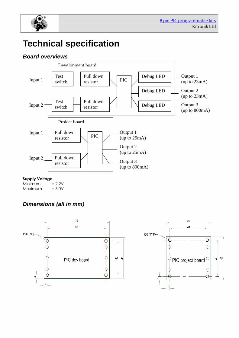
Technical specification Board overviews
Supply Voltage Minimum = 2.2V Maximum = 6.0V
Dimensions (all in mm)
Input 2
Input 1
Output 2 (up to 25mA)
Output 1 (up to 25mA)PIC
Output 3 (up to 800mA)
Pull down resistor
Pull down resistor
Project board
Input 2
Input 1
Output 2 (up to 23mA)
Output 1 (up to 23mA)
Test switch
Test switch
PIC Debug LED
Debug LED
Debug LED Output 3 (up to 800mA)
Pull down resistor
Pull down resistor
Development board

8 pin PIC programmable kits
Kitronik Ltd
The Design Process The design process can be short or long, but will always consist of a number of steps that are the same on every project. By splitting a project into these clearly defined steps it becomes more structured and manageable. The steps allow clear focus on a specific task before moving to the next phase of the project. A typical design process is shown on the right.
Design Brief What is the purpose or aim of the project? Why is it required and who is it for?
Investigation Research the background of the project. What might the requirements be? Are there competitors and what are they doing? The more information found out about the problem at this stage the better as it may make a big difference later in the project.
Specification This is a complete list of all the requirements that the project must fulfil no matter how small. This will allow you to focus on specifics at the design stage and to evaluate your design. Missing a key point from a specification can result in a product that does not fulfil its required task.
Design Develop your ideas and produce a design that meets the requirements listed in the specification. At this stage it is often normal to prototype some of your ideas to see which work and which do not.
Build Build your design based upon the design that you have developed.
Evaluate Does the product meet all points listed in the specification? If not return to the design stage and make the required changes. Does it then meet all of the requirements of the design brief? If not return to the specification stage and make improvements to the specification that will allow the product to meet these requirements and repeat from this point. It is normal to have such iterations in design projects, though you normally aim to keep these to a minimum.
Improve Do you feel the product could be improved in any way? These improvements can be added to the design.
Design Brief
Investigation
Specification
Design
Build
Evaluate
Improve

8 pin PIC programmable kits
Kitronik Ltd
Investigation / Research Using a number of different search methods find examples of similar products to that which you are going to design which are already on the market. Use additional pages if required. Name…………………………………………………………………… Class………………………………

8 pin PIC programmable kits
Kitronik Ltd
Developing a Specification Using your research into the target market for the product identify the key requirements for the product and explain why each of these is important. Name……………………………………………………………………… Class……………………………… Requirement Reason Example: The enclosure should allow easy access to the batteries.
Example: So that they can be changed by anyone when required.

8 pin PIC programmable kits Kitronik Ltd
Design Develop your ideas to produce a design that meets the requirements listed in the specification. Name………………………………………………………………… Class………………………………

8 pin PIC programmable kits Kitronik Ltd
Design Review (group task) Split into groups of three or four. Take it in turns to review each persons design against the requirements of their specification. Also look to see if you can spot any additional aspects of each design that may cause problems with the final product. This will allow you to ensure you have a good design and catch any faults early in the design process. Note each point that is made and the reason behind it. Decide if you are going to accept or reject the comment made. Use these points to make improvements to your initial design. Comment Reason for comment Accept or
Reject

8 pin PIC programmable kits Kitronik Ltd
Soldering In Ten Steps 1. Start with the smallest components working up to
the taller components, soldering any interconnecting wires last.
2. Place the component into the board, making sure it goes in the right way around and the part sits flush against the board.
3. Bend the leads slightly to secure the part.
4. Make sure the soldering iron has warmed up and if necessary use the damp sponge to clean the tip.
5. Place the soldering iron on the pad.
6. Using your free hand feed the end of the solder onto the pad (top picture).
7. Remove the solder, then the soldering iron.
8. Leave the joint to cool for a few seconds.
9. Using a pair of cutters trim the excess component lead (middle picture).
10. If you make a mistake heat up the joint with the soldering iron, whilst the solder is molten, place the tip of your solder extractor by the solder and push the button (bottom picture).
Solder Joints
Good solder joint Too little solder Too much solder

8 pin PIC programmable kits
Kitronik Ltd
Resistors A resistor is a device that opposes the flow of electrical current. The bigger the value of a resistor the more it opposes the current flow. The value of a resistor is given in Ω (ohms) and is often referred to as its ‘resistance’.
Identifying resistor values
Band Colour 1st Band 2nd Band Multiplier x Tolerance
Silver 100 10% Gold 10 5% Black 0 0 1 Brown 1 1 10 1% Red 2 2 100 2%
Orange 3 3 1000 Yellow 4 4 10,000 Green 5 5 100,000 Blue 6 6 1,000,000
Violet 7 7 Grey 8 8 White 9 9
Example: Band 1 = Red, Band 2 = Violet, Band 3 = Orange, Band 4 = Gold The value of this resistor would be: 2 (Red) 7 (Violet) x 1,000 (Orange) = 27 x 1,000
= 27,000 with a 5% tolerance (gold) = 27KΩ
Resistor identification task Calculate the resistor values given by the bands shown below. The tolerance band has been ignored.
1st Band 2nd Band Multiplier x Value Brown Black Yellow Green Blue Brown Brown Grey Yellow
Orange White Black
Too many zeros? Kilo ohms and mega ohms can be used:
1,000Ω = 1K
1,000K = 1M

8 pin PIC programmable kits
Kitronik Ltd
Calculating resistor markings Calculate what the colour bands would be for the following resistor values.
Value 1st Band 2nd Band Multiplier x 180 Ω
3,900 Ω 47,000 (47K) Ω
1,000,000 (1M) Ω
What does tolerance mean? Resistors always have a tolerance but what does this mean? It refers to the accuracy to which it has been manufactured. For example if you were to measure the resistance of a gold tolerance resistor you can guarantee that the value measured will be within 5% of its stated value. Tolerances are important if the accuracy of a resistors value is critical to a designs performance.
Preferred values There are a number of different ranges of values for resistors. Two of the most popular are the E12 and E24. They take into account the manufacturing tolerance and are chosen such that there is a minimum overlap between the upper possible value of the first value in the series and the lowest possible value of the next. Hence there are fewer values in the 10% tolerance range.
E-12 resistance tolerance (± 10%) 10 12 15 18 22 27 33 39 47 56 68 82
E-24 resistance tolerance (± 5 %) 10 11 12 13 15 16 18 20 22 24 27 30 33 36 39 43 47 51 56 62 68 75 82 91
8 pin PIC programmable kits
Kitronik Ltd
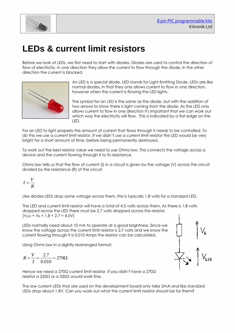
LEDs & current limit resistors Before we look at LEDs, we first need to start with diodes. Diodes are used to control the direction of flow of electricity. In one direction they allow the current to flow through the diode, in the other direction the current is blocked.
An LED is a special diode. LED stands for Light Emitting Diode. LEDs are like normal diodes, in that they only allows current to flow in one direction, however when the current is flowing the LED lights. The symbol for an LED is the same as the diode, but with the addition of two arrows to show there is light coming from the diode. As the LED only allows current to flow in one direction it's important that we can work out which way the electricity will flow. This is indicated by a flat edge on the LED.
For an LED to light properly the amount of current that flows through it needs to be controlled. To do this we use a current limit resistor. If we didn’t use a current limit resistor the LED would be very bright for a short amount of time, before being permanently destroyed. To work out the best resistor value we need to use Ohms law. This connects the voltage across a device and the current flowing through it to its resistance. Ohms law tells us that the flow of current (I) in a circuit is given by the voltage (V) across the circuit divided by the resistance (R) of the circuit.
R
VI
Like diodes LEDs drop some voltage across them, this is typically 1.8 volts for a standard LED. The LED and current limit resistor will have a total of 4.5 volts across them. As there is 1.8 volts dropped across the LED there must be 2.7 volts dropped across the resistor. (VLED + VR = 1.8 + 2.7 = 4.5V) LEDs normally need about 10 mA to operate at a good brightness. Since we know the voltage across the current limit resistor is 2.7 volts and we know the current flowing through it is 0.010 Amps the resistor can be calculated. Using Ohms law in a slightly rearranged format:
270010.0
7.2
I
VR
Hence we need a 270Ω current limit resistor. If you didn’t have a 270Ω resistor a 220Ω or a 330Ω would work fine. The low current LEDs that are used on the development board only take 2mA and like standard LEDs drop about 1.8V. Can you work out what the current limit resistor should be for them?

8 pin PIC programmable kits
Kitronik Ltd
Using a transistor as a switch
Functionality A transistor in its simplest form is an electronic switch. It allows a small amount of current to switch on or off a much larger amount of current. There are two types of transistor NPN and PNP. Both types are available in different power ratings from small signal transistors through to power transistors. The NPN transistor is the more common of the two and the one examined in this sheet. The transistor has three legs. These are the base, collector and the emitter (shown right). The emitter is always connected to 0V and the electronics that is to be switch on (the load) is connected between the collector and the positive power supply. The base of the transistor is used to switch the transistor on and off. When voltage on the base is less than 0.7V it is switched off. If you imagine the transistor as a push to make switch, when the voltage on the base is less then 0.7V there is not enough force to close the switch and therefore no electricity can flow through it and the load. This is shown by the picture below left. When the voltage on the base is greater than 0.7V this generates enough force to close the switch and turn it on. Electricity can now flow through it and the load. This is shown by the picture below right. Transistor turned off Transistor turned on
Current Rating Different transistors have different current ratings. The style of the package changes as the current rating goes up. Low current transistors come in a D shaped plastic package, whilst the higher current transistors are produced in metal cans that can be bolted on to heat sinks so they don’t overheat.
Emitter
Base
Collector
LOAD
<0.7V
LOAD
>0.7V

8 pin PIC programmable kits Kitronik Ltd
Build Instructions – Development board
Before you put any components in the board or pick up the soldering iron, just take a look at the Printed Circuit Board (PCB). The components go in the side with the writing on and the solder goes on the side with the tracks and silver pads. You will find it easiest to start with the small components and work up to the taller larger ones. If you’ve not soldered before get your soldering checked after you have done the first few joints.
Step 1 Start with the eight small resistors (shown right): R1, R2 & R4 are 10K (Brown, Black, Orange coloured bands). R3 is a 22K (Red, Red, Orange coloured bands). R5 – R8 are 1K (Brown, Black, Red coloured bands). The text on the board shows where R1, R2, etc go. Make sure that you put the resistors in the right place.
Step 2 The transistor (shown left) should be placed into Q1. It is important that it is inserted in the correct orientation. Ensure the shape of the device matches the outline printed on the PCB. Once you are happy solder the device into place.
Step 3 Solder the three Light Emitting Diodes (LEDs) as shown right in to LED1 – LED3. LED1 is the red LED. LED2 is the yellow LED. LED3 is the green LED. They won’t work if they don’t go in the right way around. If you look carefully one side of the LED has a flat edge, which must line up with the flat edge on the lines on the PCB.
Step 4 Solder the Integrated Circuit (IC) holder (shown left) in to IC1. When putting this in to the board, be sure to get it the right way around. The notch on the IC holder should line up with the notch on the lines marked on the PCB.
Step 5 Solder the programming connector (shown right) into the board where it is labeled ‘PROG’.
Step 6 Insert the two switches (see example shown left) in to the board where it is labeled SW1 and SW2. Once you have got the pins lined up with the holes they can be pushed firmly into place and soldered.

8 pin PIC programmable kits Kitronik Ltd
Step 7 The battery clip (shown right) should be soldered into the ‘POWER’ terminal. First start by feeding the wire through the strain relief hole (feed from the solder side). The red wire must go to the ‘+’ terminal (also marked ‘red’) and the black wire must go to the ‘–’ terminal (also marked ‘black’).
Step 8 There are six terminal blocks (shown left) that need to be soldered into the PCB. These should be inserted into the PCB where it is labeled IN1-IN3 and OUT1-OUT3. Add each terminal block at a time and make sure they face the edge of the PCB. Once you are happy solder into place.
Checking Your PCB Check the following before you insert the batteries:
Check the bottom of the board to ensure that: All these leads are soldered. Pins next to each other are not soldered together.
Check the top of the board to ensure that: The notch on the IC and the IC holder are in the same orientation as the markings on the
printed circuit board. The transistor Q1 is in the same orientation as the markings on the printed circuit board. The LEDs 1 to 3 are in the same orientation as the markings on the printed circuit board. R3 has Red, Red and Orange coloured bands. R1, R2 & R4 have Brown, Black, Orange coloured bands. The red wire on the battery connector goes to the ‘+’ terminal on the power terminals and the
black wire goes to the ‘–’ terminal.

8 pin PIC programmable kits Kitronik Ltd
Build Instructions – Project board Before you put any components in the board or pick up the soldering iron, just take a look at the Printed Circuit Board (PCB). The components go in the side with the writing on and the solder goes on the side with the tracks and silver pads. You will find it easiest to start with the small components and work up to the taller larger ones. If you’ve not soldered before get your soldering checked after you have done the first few joints. Step 1 Start with the five small resistors (shown right): R1, R2 & R4 are 10K (Brown, Black, Orange coloured bands). R3 is a 22K (Red, Red, Orange coloured bands). R5 is a 1K (Brown, Black, Red coloured bands). The text on the board shows where R1, R2, etc go. Make sure that you put the resistors in the right place.
Step 2 The transistor (shown left) should be placed into Q1. It is important that it is inserted in the correct orientation. Ensure the shape of the device matches the outline printed on the PCB. Once you are happy solder the device into place.
Step 3 Solder the Integrated Circuit (IC) holder (shown right) in to IC1. When putting this into the board, be sure to get it the right way around. The notch on the IC holder should line up with the notch on the lines marked on the PCB.
Step 4 Solder the programming connector (shown left) into the board where it is labeled ‘PROG’.
Step 5 The battery clip (shown right) should be soldered into the ‘POWER’ terminal. First start by feeding the wire through the strain relief hole (feed from the solder side). The red wire must go to the ‘+’ terminal (also marked ‘red’) and the black wire must go to the ‘–’ terminal (also marked ‘black’).
Checking Your PCB Check the following before you insert the batteries:
Check the bottom of the board to ensure that: All these leads are soldered. Pins next to each other are not soldered together.
Check the top of the board to ensure that: The notch on the IC and the IC holder are in the same orientation as the markings on the
printed circuit board. The transistor Q1 is in the same orientation as the markings on the printed circuit board. The LEDs 1 to 3 are in the same orientation as the markings on the printed circuit board. R3 has Red, Red and Orange coloured bands. R5 has Brown, Black, Red coloured bands. The red wire on the battery connector goes to the ‘+’ terminal on the power terminals and the
black wire goes to the ‘–’ terminal.

8 pin PIC programmable kits Kitronik Ltd
Why use a PIC micro-controller? One of the main advantages of using a PIC is that it allows some tasks to be completed with fewer parts than would otherwise be required. For example an alarm could be built using a PIC instead of two 555 timers. The 555 timer circuit needs lots of extra components to work and as a result it is bigger. This can be clearly seen if you look at the two circuit diagrams below. The circuit on the left is the alarm circuit based on the 555 timer (19 parts) and the one on the right is the PIC based circuit (11 parts).
There are a number of other advantages to using a micro-controller; some of these are outlined below. Advantages of using PIC micro-controllers:
Complex functionality can be produced a very low cost. Circuit size (as described above). It is very easy to make minor alterations to the function of the product.
o These include changing the length of the delays and the duration of sounds. o The ability to change the tone of the buzzer and even play musical tunes if so desired.
Flexibility. The circuit could easily be used for a completely different function by simply re-writing the software.
Easy to develop and debug. Most software packages allow you to simulate the software while it is being developed making it much more likely to work when used. It is also possible to break the functionality down into small steps which is easier to get right then jumping straight to the final design.

8 pin PIC programmable kits Kitronik Ltd
How the hardware works
These boards are based around an eight pin PIC microcontroller device. A PIC is in effect a small computer that behaves in a way determined by the software it’s programmed with. This software is generated by the user / student. It is this code that will determine the eventual function of the project. To aid the design of this software the following describes the function of the hardware (circuit) that this software controls.
Both boards – Processor pin mapping Terminal block IC Pin number GPIO IN1 4 3 IN2 3 4 OUT1 5 0 OUT2 6 1 OUT3 7 2 The other connections to the PIC are to provide it with power (V+ and 0V) and also allow it to be programmed with the user defined software.
Inputs Input 1 and 2. These inputs both have pull down resistors (R1 and R2) to pull the voltage on the input to the PIC to a low voltage. In the case of the development board push to make switches are connected to both the inputs. When these switches are not pressed the pull down resistors pull the voltage on the input to the PIC to a low voltage. When a switch is pressed (closed) the voltage on the PIC pin is pulled up to a high voltage. You will be able to read this change of state in your software. You can connect any type of open/closed switch between the desired input and V+ on the board.

8 pin PIC programmable kits Kitronik Ltd
Outputs Outputs 1 and 2. You can connect any output device to these two outputs provided that it doesn’t require more than 25mA (23mA on development board). Output 3. You can connect any output device to this output provided that it doesn’t require more than 800mA. Connecting a device to any of the outputs that requires more current than specified above can result in permanent damage to the PIC. The development board has debug LEDs connected to each of these outputs. When you turn the output on in the software the corresponding LED will light. The resistors R6 to R8 are needed to limit the amount of current that flows through these LEDs, which controls the brightness of the LEDs and stops them being damaged.
Other One other point worth noting is the processor clock. For any micro-controller to work it requires a clock source. The micro-controller uses this clock so that it knows when to execute the next line of software. Often these clocks are generated externally but in the chip used in this circuit the clock is built into the chip itself. This is why it does not appear on the circuit diagram.

8 pin PIC programmable kits Kitronik Ltd
Application - Decision maker As shown below by simply adding two LEDs and push to make switch you can create a random ‘yes or no’ decision maker the gives a new answer on every press of the button.
Circuit connections
Flow diagram example
IN1 Switch PIC
OUT 1 red
Pull down resistor
One side of this switch should be connected to input 1 and the other side to V+. The development board already has test switches which can be used.
The anode of the LED should be connected to output of the board and the cathode to 0V. Unless you are using a 5V LED you will also have to fit a current limit resistor in series. If you are using the development board the test LEDs could be used as these 2 LEDS.
OUT 3 green
Processor pin mapping Terminal block
Use GPIO
IN1 Make decision switch 3 OUT1 Red ‘No’ LED 0 OUT3 Green ‘Yes’ LED 2
Start
Switchpressed?
Switchpressed?
Switchpressed?
Red LED onGreen LED off
Red LED offGreen LED on
Wait 3 seconds
Both LEDs off
Yes
Yes
Yes
No
No
No
Start
Switchpressed?
Switchpressed?
Switchpressed?
Red LED onGreen LED off
Red LED offGreen LED on
Wait 3 seconds
Both LEDs off
Yes
Yes
Yes
No
No
No

8 pin PIC programmable kits Kitronik Ltd
Application - Traffic light As shown below by simply adding a red, yellow and green LED, as well as a push to make switch it is possible to make a traffic light.
Circuit connections
Flow diagram example
IN1 Switch PIC
OUT 1 Red
OUT 2 Amber
Pull down resistor
One side of this switch should be connected to input 1 and the other side to V+. The development board already has test switches which can be used.
The anode of the LED should be connected to output of the board and the cathode to 0V. Unless you are using a 5V LED you will also have to fit a current limit resistor in series. If you are using the development board the test LEDs could be used as these 3 LEDS.
OUT 3 Green
Processor pin mapping Terminal block
Use GPIO
IN1 Start sequence 3 OUT1 Red ‘go’ LED 0 OUT2 Amber ‘caution’ LED 1 OUT3 Green ‘stop’ LED 2
Start
Switchpressed?
Green LED off Amber LED on
Amber LED off Red LED on
Wait 2 seconds
Yes
No
Green LED on
Wait 20 seconds
Amber LED onRed LED on
Amber LED offRed LED off
Wait 2 seconds
Start
Switchpressed?
Green LED off Amber LED on
Amber LED off Red LED on
Wait 2 seconds
Yes
No
Green LED on
Wait 20 seconds
Amber LED onRed LED on
Amber LED offRed LED off
Wait 2 seconds

8 pin PIC programmable kits Kitronik Ltd
Application - Quiz buzzer As shown below by simply adding two push to make switches switch, two LEDs and buzzer you can create an quiz buzzer that sounds when either button is press and if both are pressed at the same time indicates which button was pressed first.
Circuit connections
Flow diagram example
IN 1 Switch PIC
LED 1 Red
LED 2 Amber
Pull down resistor
Connect switch 1 to IN1 & +V, connect switch 2 to IN2 & +V. If you are using the development board the test switches can be used.
The anode of the LED should be connected to output of the board and the cathode to 0V. Unless you are using a 5V LED you will also have to fit a current limit resistor in series. If you are using the development board the test LEDs could be used as these 2 LEDS. The negative side of buzzer should be connected to OUT3 on the board and the positive side to the +V next to it.
IN 2 Switch
Pull down resistor
OUT 3 Buzzer
Processor pin mapping Terminal block
Use GPIO
IN1 Switch team 1 3 IN2 Switch team 2 4 OUT1 Red LED (team 1) 0 OUT2 Amber LED (team 2) 1 OUT3 Buzzer 2
Start
Switch 1pressed?
Switch 2pressed?
Red LED onYes
Yes
No
No
Red LED offAmber LED off
Buzzer off
Amber LED on
Buzzer on
Wait 5 seconds
Start
Switch 1pressed?
Switch 2pressed?
Red LED onYes
Yes
No
No
Red LED offAmber LED off
Buzzer off
Amber LED on
Buzzer on
Wait 5 seconds

8 pin PIC programmable kits Kitronik Ltd
Application - Alarm As shown below by adding a key switch, a micro switch and a buzzer you can create an alarm that sounds when a draw, door etc is opened. The key switch is to allow the alarm to be activated or deactivated.
Flow diagram example
IN 1 Key switch PIC
Pull down resistor
Connect the key switch to IN1 & +V. Connect the door contact to IN2 & +V. If you are using the development board the test switches can be used to prove the concept.
The negative side of buzzer should be connected to OUT3 on the board and the positive side to the +V next to it.
IN 2 Door contact
Pull down resistor
OUT 3 Buzzer
Start
Check keyswitch?
Check doorcontact?
Buzzer on
On
Closed
Open
Off
Check keyswitch?
On
Off
Check doorcontact?
Closed
Check keyswitch?
On
Off
Buzzer off
Open
Start
Check keyswitch?
Check doorcontact?
Buzzer on
On
Closed
Open
Off
Check keyswitch?
On
Off
Check doorcontact?
Closed
Check keyswitch?
On
Off
Buzzer off
Open
Processor pin mapping Terminal block
Use GPIO
IN1 Key switch 3 IN2 Door contact 4 OUT3 Buzzer 2

8 pin PIC programmable kits Kitronik Ltd
Application - Timed motor As shown below by adding a push to make switch and motor you can create spin the motor for a defined period of time upon a press of the switch. This could be used to drive a buggy or fan.
Circuit connections
Flow diagram example
IN 1 Switch PIC
Pull down resistor
Connect the switch to IN1 & +V. If you are using the development board the test switch can be used.
The motor should be connected between +V and OUT3 on the board. You will need to connect a 100nF capacitor across the motor and also should connect a clamping diode across the motor as well. The band on the diode should go to +V connection.
Pull down resistor
OUT 3 Motor
Start
Switchpressed?
Motor on
No
Wait 30 seconds
Motor off
Yes
Start
Switchpressed?
Motor on
No
Wait 30 seconds
Motor off
Yes
Processor pin mapping Terminal block
Use GPIO
IN1 Switch 3 OUT3 Motor 2

8 pin PIC programmable kits Kitronik Ltd
Parts list
Decision maker As shown below by simply adding two LEDs and push to make switch you can create a random ‘yes or no’ decision maker the gives a new answer on every press of the button. Parts list to build 100 decision makers: Part no. Description Qty 2127 PIC 8 pin project board (2 in, 3 out) 100 3704 PICAXE-08 100 3401 Push to make switch x25 4 3504 Red 5mm LED, pack of 50 4 3003-200 220Ω resistor, pack of 100 2 2201-40 AA battery, pack of 40 8
Traffic light As shown below by simply adding a red, yellow and green LED, as well as a push to make switch it is possible to make a traffic light. Parts list to build 100 traffic lights: Part no. Description Qty 2127 PIC 8 pin project board (2 in, 3 out) 100 3704 PICAXE-08 100 3401 Push to make switch x25 4 3504 Red 5mm LED, pack of 50 4 3505 Green 5mm LED, pack of 50 4 3506 Yellow 5mm LED, pack of 50 4 3003-200 220Ω resistor, pack of 100 2 2201-40 AA battery, pack of 40 8

8 pin PIC programmable kits Kitronik Ltd
Quiz buzzer As shown below by simply adding two push to make switches switch, two LEDs and buzzer you can create an quiz buzzer that sounds when either button is press and if both are pressed at the same time indicates which button was pressed first. Parts list to build 100 quiz buzzers: Part no. Description Qty 2127 PIC 8 pin project board (2 in, 3 out) 100 3704 PICAXE-08 100 3401 Push to make switch x25 8 3504 Red 5mm LED, pack of 50 4 3003-200 220Ω resistor, pack of 100 2 3303 Piezo buzzer (no drive), pack of 10 10 2201-40 AA battery, pack of 40 8
Alarm As shown below by adding a key switch, a micro switch and a buzzer you can create an alarm that sounds when a draw, door etc is opened. The key switch is to allow the alarm to be activated or deactivated. Parts list to build 100 alarms: Part no. Description Qty 2127 PIC 8 pin project board (2 in, 3 out) 100 3704 PICAXE-08 100 2001 Key switch 100 3403 Micro switch, pack of 10 10 3303 Piezo buzzer (no drive), pack of 10 10 2201-40 AA battery, pack of 40 8
Timed motor As shown below by adding a push to make switch and motor you can create spin the motor for a defined period of time upon a press of the switch. This could be used to drive a buggy or fan. Parts list to build 100 timed fans: Part no. Description Qty 2127 PIC 8 pin project board (2 in, 3 out) 100 3704 PICAXE-08 100 3401 Push to make switch x25 4 2501 Medium torque DC motor x10 10 2201-40 AA battery, pack of 40 8


Reordering information Description Stock code PIC 8 pin development board (2 in, 3 out) 2126 PIC 8 pin project board (2 in, 3 out) 2127
Sales Phone: 0845 8380781 Fax: 0845 8380782 Email:
Technical support Phone: 0845 8380781 Email:
Every effort has been made to ensure that these notes are correct, however Kitronik accept no responsibility for issues arising from errors / omissions in the notes.
Kitronik Ltd - Any unauthorised copying / duplication of this booklet or part thereof for purposes
except for use with Kitronik project kits is not allowed without Kitronik’s prior consent.