+61 (0) 2 6686 8408 | 4/1 ... · Tall flues may need bracing, ... · The largest cylinder must...
49
www.aurorasuspendedfires.com +61 (0) 2 6686 8408 | 4/1 Simmons Street | Ballina NSW 2478, Australia
-
Upload
dangkhuong -
Category
Documents
-
view
212 -
download
0
Transcript of +61 (0) 2 6686 8408 | 4/1 ... · Tall flues may need bracing, ... · The largest cylinder must...

www.aurorasuspendedfires.com
+61 (0) 2 6686 8408 | 4/1 Simmons Street | Ballina NSW 2478, Australia

CONTENTS
1. PLANNING 03 INTRODUCTION 04
CLEARANCE TO COMBUSTIBLES 05
FLUE POSTION 06
2. DIMENSIONS & SPECIFICATIONS 09 THE AETHER 10
THE HEARTH 11
MINIMUM TOTAL FLUE LENgTH 12
3. INSTALLATION 13
SUSPENSION BRACKET 14
LOWER FLUE 17
FLUE ADAPTOR 19
EXTERNAL FLUE 20
FIREBOX 22
FLOOR PROTECTOR REQUIREMENTS 24
BIOETHANOL FIREPLACE 26
BIOETHANOL - WOOD HYBRID 28
FOR INSTALLERS 29
INSTALLATION CHECKLIST 30
4. CARING FOR YOUR PAINT 31
INITIAL START UP 32
CLEANINg & MAINTAININg YOUR PAINT 34
CARINg FOR YOUR OUTDOOR FIREPLACE 35
5. OPERATION 37
WOOD BURNINg 38
6. CERTIFICATION & wARRANTY 44
We would like to thank you for your purchase of an Aurora Suspended Fire. The care and craftsmanship we put into each fire will give you trouble free heating for many years to come.

1.PLANNINg
installation and user manual
04
! Mixing of appliance or flue-system components from different sources or modifying the dimensional specification of components may result in hazardous conditions. Where such action is considered, Aurora fires should be consulted in the first instance.
INTRODUCTION
planning1
For your safety, ensure you have read the operation guidelines prior to use. Your fire should be installed by a qualified professional. Refer to our website for assistance finding an installer in your area: www.aurorasuspendedfires.com/support/find-installer/
INSTALATION PROCESS
1. Choose the position of firebox and flue ensuring that you follow the clearances described within this section
2. Install the suspension bracket
3. Install the internal flue
4. Install the flue adaptor
5. Install the external flue & anti-down draught cowl
6. Engage the firebox
7. Ensure the floor has adequate protection
wARNING
· The appliance and flue system shall be installed in accordance with AS/NZS 2918 and the appropriate requirements of the relevant building code or codes.
· Appliances installed in accordance with this standard shall comply with the requirements of AS/NZS 4013 where required by the regulatory authority, i.e. The appliance shall be identifiable by a compliance plate with the marking ‘tested to AS/NZS 4013’.
· Any modification of the appliance that has not been approved in writing by the testing authority is considered to be in breach of the Approval granted for compliance with AS/NZS 4013.

aurora suspended fires
05
CLEARANCE TO COMBUSTIBLES
A combustible surface is anything that can burn (i.e. plaster, wall paper, wood, fabrics etc.)These surfaces are not limited to those that are visible, but also include materials that are behind non-combustible material. Timber frames behind gyprock are considered combustible.
important Window frames must also be considered. Timber window frames must be treated as combustible surfaces.Aluminium frames can be treated as non-combustible
rEDUCinG CLEaranCE to ComBUStiBLES Please refer to the ‘Help’ section of our website for further information on reducing clearances safely.
wall
wa
ll
flue
firebox
wall Material Postion of Firebox
Firebox to Combustible
Ceiling Dropbox to Combustible
Flue to Combustible
Non-Combustible Fixed 100mm 25mm 100mm
Non-Combustible Rotating 100mm 25mm 100mm
Combustible Fixed 700mm 25mm 700mm
Combustible Rotating 1200mm 25mm 700mm

installation and user manual
06
planning1
FLUE POSITION
FLUE HEIGHTS AND TERMINATION
The minimum flue height recommended for optimum performance of our fireplaces is 4.5 m from the top of the firebox to the top of the external flue. It is best to position the flue so that it goes straight up as near to the roof ridge as possible. The diagram over page shows the minimum flue discharge heights and positions for all wood burning and multi fuel applications.
In some cases, particularly when flues are towards the bottom of a sloping roof or at the eaves, it may be necessary to increase the flue height above these minimum mandatory requirements. The reason for this is to clear pressure zones created by wind hitting the roof and nearby structures, like trees, which may interfere with the up draught required by the appliance or fire.
Tall flues may need bracing, always consult your installer for advice.
»POSITIONING THE ExTERNAL FLUE
FLAT ROOF INSTALLATION Less than 5%
1. The top of the flue must be 60cm above the roofline. Alternatively, there must be a minimum distance of 3 meters from any higher section of roof.
2. Ensure the triple skin flue is installed as per Australian standards (see diagrams below).

aurora suspended fires
07
The minimum height of the flue system further than 3 meters from the highest point of the roof shall be 1 meter above roof penetration.
60cm
3m
1m
60cm

installation and user manual
08
1 planning
The minimum height of the flue system further than 3 meters from the highest point of the roof shall be 1 meter above roof penetration.
» PITCHED ROOF INSTALLATION
1. The top of the flue must be 60cm above the roofline. Alternatively, there must be a minimum distance of 3 meters from any higher section of roof.
2. Ensure the triple skin flue is installed as per Australian standards (see diagrams below).
60cm
3m
1m

2.DIMENSIONS
& SPECIFICATIONS

installation and user manual
10
THE AETHER
dimensions & specifications 2
FEATURES
· Stainless steel ball bearing 360 degree rotation system
· Custom flue length with damper
· Material: 4mm Steel or Stainless Steel
· Finish: high temperature coating system.
· Heat Output: 8.2kW
· Colour: matte black (A range of other colours are available on request. For more information visit our website.)
Firebox diameter 900mm
Firebox weight 55kg
Flue diameter 165mm
Flue weight 12kg/meter
Standard bracket weight 23kg
External flue kit Triple skin 6/8/10 inch
grate 22kg
wEIGHT & DIMENSIONS
172mm
165mm
900mm
842mm

aurora suspended fires
11
THE HEARTH
FEATURES
· Stainless steel ball bearing 360 degree rotation system
· Flue custom length with damper
· Material: 4mm Steel or Stainless Steel
· Finish: high temperature coating system.
· Heat Output: 7.2kW
· Colour: matte black (A range of other colours are available on request. For more information visit our website.)
Firebox diameter 900mm
Firebox weight 55kg
Flue diameter 165mm
Flue weight 12kg/meter
Standard bracket weight 23kg
External flue kit Triple skin 6/8/10 inch
grate 12kg
wEIGHT & DIMENSIONS
165mm
900mm
230mm
600mm

installation and user manual
12
dimensions & specifications 2
MINIMUM TOTAL FLUE LENgTH
suspension bracket/drop box
lower active flue
damper handle
internal rotation assembly
firebox
grate
ash removal tray
The minimum total flue length (lower & external triple skin flue combined) is 4.5 metres measured from the point the firebox joins the flue to the top of the triple skin flue.

3.INSTALATION
installation and user manual
14
installation3
SUSPENSION BRACKET
FLAT ROOF INSTALLATION
· The bracket must be structurally secured within the roof as shown in the diagram
· The largest cylinder must protrude down from the ceiling by at least 25mm unless the ceiling is made from a noncombustible material such as concrete.
· You must leave a 25mm clearance gap between the bracket and the ceiling. This gap will be covered by the ceiling cover plate.
· 12mm ventilation gap between the plasterboard and the ceiling cover plate.
· 25mm minimum clearance from the triple skin flue to any combustible material within the roof space.
Aurora Suspended Fireplaces are suitable for almost any installation, below are examples of what is possible.
· Outdoor fireplace on a covered deck
· 2 story through both levels installation
· 2 storey through lower level and out up the side of the house with an offset
· Pitched roof with open beams
· Cathedral ceilings
· Single story
»

aurora suspended fires
15
the largest cylinder must protrude down from the
ceiling by at least 25mm unless the ceiling is made
from a non-combustible material such as concrete
ceiling cover plate12mm ventilation gap between plasterboard and ceiling cover plate
connector in the top of the lower active flue
support to span across ceiling joists
lower active flue
ceiling
25
25 25

installation and user manual
16
installation3
PITCHED ROOF INSTALLATION Custom Made
For pitched ceilings we have 5 bracket sizes which your installer will adjust to achieve the exact angle for your installation.
· Up to a 5 degree pitch = Flat bracket
· 5 to 15 degree pitch = 10 degree bracket
· 15 to 25 degree pitch = 20 degree bracket
· 25 to 35 degree pitch = 30 degree bracket
· 35 to 45 degree pitch = 40 degree bracket
A custom bracket is available for anything larger than a 45 degree pitch. When installing the bracket, it is very important that the bracket is sitting plumb.
The installer may need to chock up one side of the bracket, with non combustible material i.e. cement sheet.
»
lenght to suit pitch of roof
ceiling
ceiling cover plate
12mm
25mm
25mm

aurora suspended fires
17
LOWER FLUE
LOwER FLUE LENGTHS
We supply the lower flue in the standard sizes listed below. The extra length will be pushed up into the drop box, enabling you to set the correct distance of the firebox to the floor.
FLUE LENGTHS
1.6m 2.75
1.8m 3.0m
2.0m 3.25m
2.25m 3.5m
2.5m Custom
Sizes above 3.5m will come in two pieces, with an internal joiner.
INSTALLING A TwO PIECE LOwER ACTIvE FLUE
Lower active flues over 3.5 metres are supplied in two parts and are joined internally with a flue connector. This assists installers in achieving a safe and successful installation. Do not attempt to join these prior to attaching to the suspension bracket.
1. Attach the upper piece to the suspension bracket first
2. When this is in place attach the lower part.
INSTALLING THE INTERNAL LOwER ACTIvE FLUE
The lower active flue is delivered with additional length to allow for small changes to set the correct firebox height.
1. First position the lower active flue inside the suspension bracket to obtain the correct height.

installation and user manual
18
installation3
2. For aesthetic reasons the lower flue should be positioned with the seam facing away from the front of the fire (this wont be possible for installations in the centre of the room). As you are facing the fire the flue damper will be on the right hand side of the flue. For a centrally placed installation position the seam on the side which will be least visible.
3. Once the desired height is achieved tighten the 6 grub screws. Use a level to ensure that the flue is perfectly vertical.
important Lower flue pushed up a minimum 200mm into the dropbox (200mm measurement taken from the point the lower flue enters the dropbox connector). Mark the flue with chalk to assist with this.
lower flue inserted minumum200mm from bottomof dropbox connector
grub screwsonce the 6 grubs screws are tightened, the lower flue is secure and willnot move
aether: 1020mmhearth: 1090mm
dropboxconnector
minimum 200mm
floor or floor protector
aurora suspended fires
19
FLUE ADAPTOR
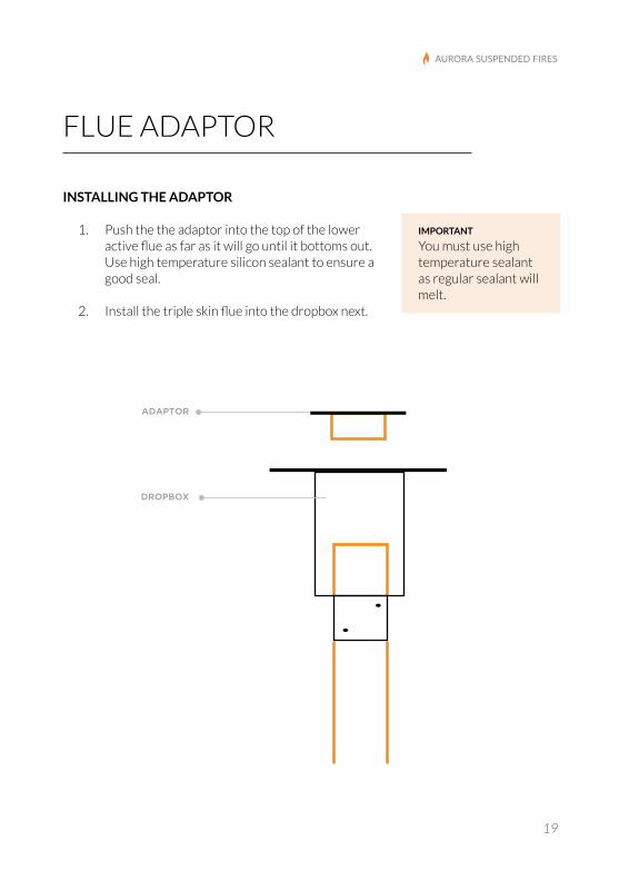
INSTALLING THE ADAPTOR
1. Push the the adaptor into the top of the lower active flue as far as it will go until it bottoms out. Use high temperature silicon sealant to ensure a good seal.
2. Install the triple skin flue into the dropbox next.
important You must use high temperature sealant as regular sealant will melt.
dropbox
adaptor

installation and user manual
20
installation3
ASSEMbLING THE ExTERNAL FLUE*
· Crimps on 6 inch stainless flue to point down.
· Crimps on 8 & 10 inch flue to point up.
· The first 6 inch stainless flue has the adaptor connected to it.
MINIMUM TOTAL FLUE LENGTH
Minimum total flue length (lower & external triple skin flue combined) is 4.5 metres for optimal performance.
EXTERNAL FLUE
anti down draught cowl
6” stainless steelflue pipe (hot pipe)
8” galvanised steelintermediate pipe
10” galvanised steel outer pipe optional colorbond available
roof flashing(not supplied by aurora)
dropbox
adaptor25mm minumum
*Please refer to page 20 for a step by step guide to installing first length of 6 inch flue.

aurora suspended fires
21
INSTALLING THE ANTI DOwN DRAUGHT COwL
An anti-down draft cowl is provided with your Aurora fire. These have been tested with our fires and workwell.
Occasionally your installer may recommend the use of another type of cowl, depending on the position of your external flue, in relation to the surrounds.
INSTALLING OFFSETS IN THE TRIPLE FLUE
If the flue requires an offset the following guidelines must be adhered to:
· 2 x 45 degree offsets are the maximum allowable.
· 600mm minimum run centre to centre.
When installing the offsets, it is advisable to use bracing, to ensure the connection to the lower active flue does not get disturbed.

installation and user manual
22
installation3
FIREBOX
ENGAGING THE FIREbOx
Assemble the shaft & bearing system in the following order:
1. Engage the firebox.
2. Push the bearing over the shaft in the order it is shipped.
3. Push the bearing cap over the bearing .
4. Tighten the first 16mm nut. The firebox should rotate freely. If necessary back the nut off slightly until the firebox rotates freely.
5. Tighten the second 16mm nut against the first.
notE The bearing is shipped in the correct order on the shaft. The bearing must be installed in the correct order or the firebox will be too loose.
important Ensure the threaded shaft does not knock against the firebox when engaging. This can damage the thread.

aurora suspended fires
23
LOCkING THE FIREbOx IN A FIxED POSITION
If the firebox is 700mm or closer to combustibles the firebox must be locked in a fixed position.
To do so tighten the first nut until the firebox is unable to rotate.
INSERTING THE GRATE
It is recommended that you place a protective cloth over the lip of the firebox when inserting or removing the grate to prevent scratching the paint.
Item Part Number QTY
1 Pivot-Upper Plate Inside Flue 1
2 Ball Bearing Shaft 1
3 Pivot Lower Plate Inside Firebox 1
4 Stainless Thrust Bearing 1
5 Ball Bearing Cap 1
6 16mm Nut 2
1
2
3
4
5
6

installation and user manual
24
installation3
FLOOR PROTECTOR REQUIREMENTS
You will require a hearth to protect any combustible floor beneath the firebox. Your floor protection must extend 30cm beyond the diameter of the firebox in all directions.
If installed directly on combustible material, the floor protector must be made of a 12mm thick sheet of non combustible material.
If the combustible floor is installed on concrete, you can replace the combustible material with a non-combustible material laid directly onto the concrete.
Floor protectors can be made of non combustible materials such as:
· Tile
· Stone
· Steel
· Toughened glass
· Polished Concrete
View the floor protector page on our website for inspiration.
See over page for height specifications.

aurora suspended fires
25
Floor Protector Location Floor Protector Details
Floor protector laid directly onto timber floor
12mm thick non combustible material
Floor protector laid directly onto concrete, with combustible floor surrounding it
12mm thick non combustible material
30cm
650mm
30cm
aether: 450mm hearth: 560mm
floor protectorfloor
installation and user manual
26
installation3
BIOETHANOL FIREPLACE
The fireplace (the Aether or the Hearth) is fitted with either a scope 340 EcoSmart grate insert & stainless steel burner or an EcoSmart XL500 burner which both use bioethanol fuel.
The burner comes fitted with a grate designed for our fireboxes. As bioethanol gives of nothing but water vapour there is no need for an external flue, therefore the lower active flue will be capped inside the suspension bracket. Fit the lower active flue as normal and then put the flue cap onto the end, inside the suspension bracket and tighten the 4 grubs screws. This will stop any heat transference into your roof space.
notE To install the bioethanol fireplace please follow the instructions on pages 15-19 and 23-24.
See over the page for instructions on inserting the bioethanol burner and grate.

aurora suspended fires
27
bIOETHANOL FIREPLACE CLEARANCES
1. Locate the bioethanol burner onto the burner tray supplied with your fire.
2. Check that the burn chamber is in the centre of the firebox.
3. Insert the grate.
4. Ensure the opening in the grate lines up with the bioethanol burner.
For instructions on lighting the burner refer to the EcoSmart instructions in the burner box.
Wall MaterialPostion Of Firebox
Firebox/Flue To Combustible
Ceiling Dropbox To Combustible
Non combustible Fixed 100mm 25mm
Non combustible Rotating 100mm 25mm
Combustible Fixed 100mm 25mm
Combustible Rotating 100mm 25mm

installation and user manual
28
installation3
BIOETHANOL - WOOD HYBRID
bIOETHANOL wOOD-HYbRID FIREPLACE INSTALLATION
The bioethanol/wood hybrid is a fully flued wood fireplace with a custom fitted bioethanol burner as an added extra.
You receive two grates, one for burning wood and one for bioethanol. When you wish to burn wood you simply swap grates and remove the bioethanol burner.
To get maximum available heat output when using the bioethanol burner the damper must be fully closed during operation. This will keep the warmth from escaping out the flue system.
notE This only applies to bioethanol operation. The damper must be fully open at all times when burning wood.
To install the Bio Ethanol-Wood Hybrid follow the installation instructions for standard wood fire installation.
See previous page for bioethanol burner & grate installation.

aurora suspended fires
29
FOR INSTALLERS
CLEANING UP
If the fire paint has accumulated dust, fingerprints or other residue during installation Wipe the firebox and lower flue down with a little water and a scratch free glass polishing cloth. Use a light spray of WINDEX if required.
DO NOT RUB THE PAINT. A LIgHT PRESSURE IS ALL THAT IS NEEDED.
HANDING OvER CHECkLIST
Read the Users instructions and instruct the user on the operation of the fireplace and cleaning methods. Leave instructions with the customer.
Inform the customer that any odours are due to the newness of materials and will disperse after the initial burn instructions are followed.
Advise the customer on the operation of the flue damper.
Advise the customer on the importance of an adequate air supply.

installation and user manual
30
installation3
INSTALLATION CHECKLIST
INSTALLATION MUST TAkE PLACE IN THE FOLLOwING ORDER
Suspension bracket installed plumb and clear of combustibles. Dropbox to protrude minimum 25mm below ceiling. More than 25mm should only be used if the roof space prohibits a 25mm drop.
25mm clearance gap between the bracket and the ceiling. This gap will be covered by the ceiling cover plate.
Lower active flue installed BEFORE triple skin flue & set to correct height from floor.
Lower flue pushed up a minimum of 200mm into the dropbox (200mm measurement taken from the point the lower flue enters the dropbox flue connector). Mark the flue with chalk to assist with this.
Flue seam facing the back of the fire, if possible.
Grub screws tightened.
6 inch stainless flue adaptor pushed into the top of the lower active flue as far as it will go until it bottoms out & sealed with a high temp silicone sealant. If this is not done correctly, it may result in a weak draw.
Flue adaptor sealed correctly.
Triple flue installed to make up a total flue height (internal flue & triple flue) of 4.5m minimum.
25mm minimum clearance from the triple skin flue to any combustible material within the roof space.
Triple skin flue sealed with a high temp silicone sealant & flashing installed. Braced ( if required). If necessary precautions against capillary action taken.
Anti-down draft cowl installed.
Firebox lifted into position evenly to protect the shaft from damage. Bearings and nut installed in the correct order and tightened to close the gap between firebox and lower flue to approximately 1mm to 2mm. Firebox rotates freely, if required.
important This must be ticked and signed by the person who installs your fire and returned to aurora suspended fires following installation for any warranty claims to be honoured.
name
signature
date

4.CARINg FORYOUR PAINT

installation and user manual
32
INITIAL STARTUP
HIGH TEMPERATURE PAINT INITIAL FIRING PROCESS
Your fire has been painted with the highest quality coating used in the heating appliance industry.
We have selected Stove Bright® brand coatings because the product has been proven durable, colourfast, and beautiful at high temperatures.
To optimise the performance of the coating, and to maximise its durability, it needs to go through an initial burn process.
Your fire is delivered to you already cured in a curing oven, which greatly reduces the smoke & odours associated with the initial burn. However the paint will still continue to settle over the first few burns. Therefore it is important that you follow the initial burn instructions to maximise the life of your paint and for your own comfort and safety.
The fires heat-proof finish only hardens completely once the initial burn process is complete.
When unpacked, it is therefore not fully hardened. It can easily be damaged at this time so care must be taken to protect the paint prior to the initial burn.
This process is explained on the next page and should be followed as closely as possible during the first two burns of your new suspended fireplace. Once this initial firing process is successfully completed, the coating will bond to the metal with a colourfast finish that will last.
important Initial startup is for your safety & the longevity of your fire.
4 caring for your paint

aurora suspended fires
33
notE During the initial firing process there are changes in the paint causing it to give off an odour and some visible smoke. The fumes can be unpleasant.
Do the following BEFORE you fire the fire for the first two times:
1. Ventilate. Open doors and windows in the room with the stove. To speed dissipation of odour from the initial firing process, you can place a fan in the room to move the air.
2. Vacate.The fumes from the initial heating process are non-toxic, but may be uncomfortable for babies, small children, pregnant women, elderly, pets, or anyone with breathing difficulties.
3. Clean. Wipe down the firebox to remove any dust or finger prints. You won’t have to do this prior to every burn once the paint is fully cured.
INITIAL FIRING PROCESS
1. Slowly build up a small to medium size fire, over a period of 45 minutes. The outside of the firebox temperature will be about 200 degrees C. The fire will measure approximately 300mm diameter. Allow the fire to die down and allow the firebox to cool.
2. Repeat this process, increasing to a medium sized fire (approximately 350mm). This will burn at around 230 to 250 degrees C. Allow the fire to die down and allow the firebox to cool again.
Your firebox paint will now be cured and any unpleasant odours will be gone.

installation and user manual
34
4 caring for your paint
CLEANINg & MAINTAININg YOUR PAINT
The outside of the firebox & lower flue can be cleaned with a scratch proof glass polishing cloth and a little water. Be sure to wipe dry after cleaning.
For particularly hard to move marks Windex can be used and is very effective. This is best kept to occasional use as over the long term it may begin to wear your paint.
NEVER USE ABRASIVE CLEANERS ON THE PAINT. Abrasive cleaners will remove the paint.
Minor scratches can be touched up using a Stove Bright Aerosol paint in the same colour as your fire.
NEVER BURN YOUR FIRE WHEN IT IS WET as this will damage the paint. For outside fireplaces that are especially vulnerable to rain please see detailed instructions on the next page.
Please visit the Stove Bright website for a range of easy to follow video’s which will take you through the process of touching up your paint: www.forrestpaint.com/stove-bright/how-tos-with-stove-bright

aurora suspended fires
35
CARINg FOR OUTDOOR FIREPLACES
Our outdoor fireplaces are coated with a zinc paint to prevent rust. Extra care will ensure the longevity of your fireplace.
If you live near a beach or if your fireplace is installed near your swimming pool, your fireplace will be more prone to minerals settling on the surface of the fireplace which can damage the paint over time if care is not taken to prevent this.
Follow these guidelines for cleaning & maintaining your outdoor fireplace:
· Your outside fireplace must be installed in an area that is covered to prevent excessive exposure to rain
· keep it Clean – Accumulated dirt and debris can hold moisture and allow corrosion to occur even on a dry day. Periodically wiping down the firebox and lower flue following the steps outlined on the next page can help avoid paint damage in the long run.
· keep it dry - never light your fireplace when the surface is wet as the minerals in the water will stain the paint.
If your fireplace has been exposed to rain always wipe down your fireplace prior to use, following the steps below to remove mineral deposits from the surface of the steel. Any minerals from the rain left on the steel when it is burnt will damage the paint.

installation and user manual
36
caring for your paint4
CLEANING METHOD
All cleaning and maintenance must be done when the appliance is cool.
Do NOT use oven cleaners or abrasive products as they will damage the paint.
1. Wipe all surfaces with a mild soap with a scratch free glass polishing cloth.
2. For stubborn marks or grease use WINDEX and a scratch free glass polishing cloth. Don’t scrub the paint. gentle pressure only.
3. Wipe dry with scratch free glass polishing cloth.
4. Ensure surface is completely dry before lighting the fire.
For comprehensive trouble shooting tips, answers to FAQ and fireplace articles, fact sheets and interest pieces visit the ‘Support’ section on our website: www.aurorasuspendedfires.com/support/

5. OPERATION

installation and user manual
38
wHAT YOU SHOULD bURN
· Maximum load capacity: No more than four large logs (not exceeding 110mm in diameter) at a time.
· Untreated, air dried hardwood
· Split logs with a humidity content of less than 20%
DO NOT bURN
· Trash
· Painted plastic
· Coated or preservative treated wood
· Waste or black coal
· Inflammable liquids
· Fire gels
· Moist wood with a residual humidity content of more than 20% (this may cause soothing of the chimney).
Trouble Shooting: Please get in touch with us on the details below or refer to our FAQ page for trouble shooting on the operation of your firebox: www.aurorasuspendedfires.com/support/faq/
important Misuse may lead to unhealthy and environmentally harmful emissions and will void any warranty or guarantee. Burning only seasoned hardwood helps to protect the environment and lower emissions.
WOOD BURNINg
5 operation
aurora suspended fires
39
· Do not use flammable liquids or aerosols to start or rekindle the fire.
· Do not use flammable liquids or aerosols in the vicinity of this appliance when it is operating.
· Do not store fuel within heater installation clearances.
· This appliance should be maintained and operated at all times in accordance with these instructions.
· The use of some types of preservative-treated wood as a fuel can be hazardous.
· Do not touch the firebox or flue when hot.
OvER FIRING DO NOT OVER-FIRE. Over-firing may damage the fire and the paint.
To Prevent Over-Firing, DO NOT:
· Use flammable liquids
· Overload with wood
· Burn trash or large amounts of scrap lumber
SYMPTOMS OF OvER-FIRING
Symptoms of over-firing may include one or more of the following:
· Flue or appliance glowing
· Paint peeling or bubbling.
· Roaring, rumbling noises
!
important Aurora Suspended Fires WILL NOT warranty fires that exhibit evidence of over-firing. Evidence of over-firing includes, but is not limited to: bubbling, cracking and discolouration of steel or painted finishes.

installation and user manual
40
5 operation
LIGHTING A FIRE
What To Burn Use dry split wood for best results. Using wet wood will result in a smokey fire that is hard to get started and gives off low heat. Bunnings stock appropriate split dry wood & kindling as do most service stations.
If you are drying your own wood keep in mind that wood only begins to dry seriously once it is spilt to correct size.
Allow around six months for proper drying to take place.
We recommend split wood rather than round logs as they burn better and are less prone to rolling away from the ember bed.
Before Lighting Your Fire Check that the damper is fully open. The handle should be pointing down. The fire must be operated with the damper fully opened at all times.
STARTING A FIRE
You will need the following materials to build and maintain a good wood fire
· A fire lighter or newspaper (do not use coloured or coated paper)
· A handful of finely split, dry kindling in a variety of sizes
· Seasoned firewood split into a range of sizes
THE MOST RELIAbLE METHOD FOR LIGHTING OUR OPEN FIREPLACES
It is important to keep in mind that Aurora Fireplaces are open fireplaces and cannot be loaded or operated in the same way as a combustion (closed) fireplace. If you’re

aurora suspended fires
41
used to a combustion fireplace this method may take a little getting used to, however it is absolutely reliable, and when it is done properly there is almost no smoke right from the start.
The most important part of this whole process is to use dry, seasoned firewood. The fire works by having the coals and embers from the top layer fall into the layer of wood below it. If the wood is wet it won’t catch on fire and you’ll become frustrated.
1. Place two split pieces of timber approximately 40mm thick x 300mm long on the grate with the ends facing front and back. Placement with the ends facing front and back allows the air to mix well with the fuel, rather than just hitting the sides of the wood.
2. Place a fire-lighter or one piece of scrunched up newspaper in-between them.
3. Stack two pieces of kindling approximately 30mm thick x 300mm long on top of the bottom pieces criss crossing in the other direction.
4. Follow this by stacking a third row of fine kindling 20mm thick x 300mm long on top, criss crossing in the other direction.
5. Repeat step four.
6. Light the fire lighter or paper and watch as the fire burns down through the fine kindling and the kindling into the bottom pieces of split timber.
7. Once the timber is well alight start adding more 40mm thick pieces of timber 1 or 2 at a time, slowly increasing the timber size as the fire burns

installation and user manual
42
operation5
TROUbLE SHOOTING
Crack a window Fireplaces require large volumes of air to burn. This air comes from inside the living area and must somehow be replaced. With modern energy efficiency concerns, most houses have been carefully insulated and weather-stripped to keep out the cold drafts, but an undesirable side effect is that there is often nowhere for all that air leaving through the chimney to get back in.
This can lead to fireplaces that burn sluggish and smoky. To counter that, open up a window a crack. This works best if the window is on the side of the house that the wind is blowing from. We want to push air into the fire and up the flue, not suck air out of the fire into the room.
Turn Off Exhaust Fans When the an exhaust fan is on, air is drawn into the return vent and competes directly with the air needs of the fireplace. Air (smoke) will be pulled into the room.
Cowls Your fire needs to be fitted with an approved cowl that is appropriate for the topographical conditions affecting your flue system. It must be either a standard anti downdraft cowl or, in some cases, a specialised cowl. A rain cap will not be sufficient for your fire to perform optimally.
A standard anti downdraft cowl is the best type of cowl for 90% of installations. In certain situation you may require a specialised cowl designed to combat the weather and landscape/structural conditions of your installation. Contact a qualified installer for advice on the right cowl for you.
Too Much Wood Too much wood at once will overload the cowl and flue system with smoke, causing smoke spillage into the room. Check the recommended load, fuel type and guidelines for building an effective fire on the previous pages of this manual.

aurora suspended fires
43
Too Little Wood An undersized fire will not create enough draft in the flue, allowing the smoke to spill into the room. The fire will not heat up effectively enough to circulate the convection air.
The Prevailing Wind & Topography Of the land The slope and position of the land and surrounding buildings or trees in relation to the flue system has a bearing on how the wind will interact with the fire and flue system. Wind that hits the flue system may overcome the cowl and draft back down the flue. Care must be taken to ensure that the flue termination is in the correct position to maximise performance.
For comprehensive trouble shooting tips, answers to FAQ and fireplace articles, fact sheets and interest pieces visit the ‘Support’ section on our website: www.aurorasuspendedfires.com/support/

44
6.CERTIFICATION& WARRANTY

aurora suspended fires
45
tESt rEport nUmBEr 30A-14-0097-TRP-358755-0
titLE Aurora Aether & Hearth Fires Installation Clearance Test
work rEqUEStED Assessment of appliance to AS/NZS:2918:2001 Appendix B, with a full-length supplied flue kit.
tESt DatES 12 January 2015 to 26 January 2015
tEStinG LaBoratory Vipac Engineers & Scientists
manUfaCtUrEr Aurora Wood Fires Pty Ltd
moDELS The Aether & The Hearth
ConCLUSion These appliances comply with the requirements of AS/NZS 2918:2001 Appendix B for the configurations tested.
tESt rEport nUmBEr 30A-14-0097-TRP-359162-0
titLE Aurora Models Aether & Hearth CO2 Emissions Testing.
work rEqUEStED Measure CO2 outputs in accordance with AS/NZS 4013:2014 for the determination of exclusion from full testing for both units.
tESt DatES 25 January 2015 to 30 January 2015
tEStinG LaBoratory Vipac Engineers & Scientists
manUfaCtUrEr Aurora Wood Fires Pty Ltd
moDELS The Aether & The Hearth
ConCLUSion This appliance meets the requirements of AS/NZS 4013:2014
AUSTRALIA & NEW ZEALAND STANDARDS AS/NZS:2818 & AS/NZS:4013
installation and user manual
46
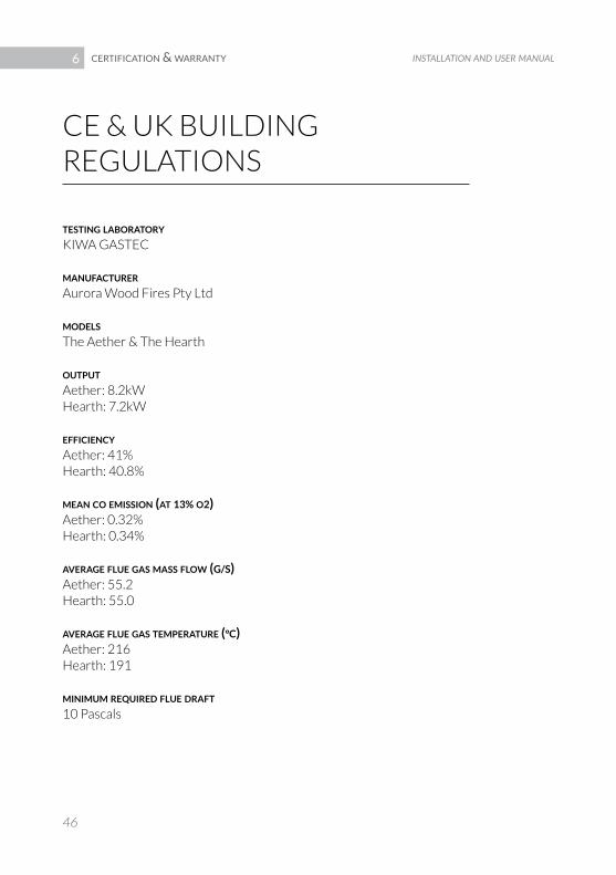
CE & UK BUILDINg REgULATIONS
tEStinG LaBoratory KIWA gASTEC
manUfaCtUrEr Aurora Wood Fires Pty Ltd
moDELS The Aether & The Hearth
oUtpUt Aether: 8.2kW Hearth: 7.2kW
EffiCiEnCy Aether: 41% Hearth: 40.8%
mEan Co EmiSSion (at 13% o2) Aether: 0.32% Hearth: 0.34%
avEraGE fLUE GaS maSS fLow (G/S) Aether: 55.2 Hearth: 55.0
avEraGE fLUE GaS tEmpEratUrE (°C) Aether: 216 Hearth: 191
minimUm rEqUirED fLUE Draft 10 Pascals
certification & warranty6

aurora suspended fires
47
We guarantee the structural integrity of our firebox, lower active flue and ceiling bracket for a period of 5 years from the date of purchase. Defects to the listed components that occur within this warranty period will be repaired or replaced at our discretion. The benefits conferred by this warranty are in addition to all rights and remedies the consumer has under the Competition & Consumer Act 2010 and similar state and territory laws.
Our goods come with guarantees that cannot be excluded under the Australian Consumer Law. You are entitled to replacement or refund for a major failure and for compensation for any other reasonably foreseeable loss or damage. You are also entitled to have the goods repaired or replaced if the goods fail to be of acceptable quality and the failure does not amount to a major failure.
THE wARRANTY ExCLUDES
· Failure or damage due to fair “wear & tear” incurred on the product during the course of normal use.For the purposes of the warranty, fair “wear & tear” is defined as degradation consistent with that expected for a product of its age, when used in the regular manner and in the normal application the product was designed for, as assessed by Aurora Suspended Fires.
· Any components which are subjected to particularly high temperatures which have worn out, such as the paint of the firebox & flue, grate of the firebox and its ash removal pan, damper rod & ball bearing system are not covered by this warranty.
AURORA SUSPENDED FIRES WARRANTY

installation and user manual
48
· Any product where a modification to the original product has occurred, or where the product casing has been opened, or where actual or attempted repair work on the product has been carried out by anyone other than an Aurora Suspended Fires authorised service technician, or where a repair used non- genuine Aurora Suspended Fires parts.
· Any damage which occurs due to errors in installation is not covered by the warranty, since the manufacturer does not have any control over the way in which the unit is installed. In order to work properly, our fireplaces must be installed according to the overall rules governing such work and any current standards and regulations must be strictly adhered to.
· Products purchased from an unauthorised Aurora Suspended Fires reseller, including on- line trading companies or individuals (e.g. Trading Post, eBay etc) that are not authorised Aurora Suspended Fires resellers.
warranty poLiCy This warranty applies as long as the recommendations for use and assembly, and the standards and legislation that apply are fully adhered to. Please consult this installation & user manual for recommendations on installing, operating and maintaing your fireplace.
Aurora Suspended Fires reserves the right to review and amend its warranty policies and periods on all products, repairs, service parts & accessories, from time me to time me as Aurora Suspended Fires considers appropriate.
certification & warranty6

aurora suspended fires
+61 (0) 2 6686 8408 4/1 Simmons Street
Ballina NSW 2478, Australia
www.aurorasuspendedfires.com
Aurora


![8408-11 EC International Prospectus V5[Single Pages]](https://static.fdocuments.in/doc/165x107/577ce6df1a28abf10393d124/8408-11-ec-international-prospectus-v5single-pages.jpg)