
581A TELEPHONE SET BASES - VoIP Lines & Hosted...
27
BELLSYSTEM PRACTICES SECTION 503-100-120 AT&TCo Standard Issue 4, August 1978 581A TELEPHONE SET BASES 1. GENERAL • Cord, mounting, D10R-* (specify length) [when rotary dial set is used with 1A1 or 1.01 This section contains identification, installation, 1A2 KTS and 3B (MD) or 4-type speakerphone] connections, and maintenance information for the 581A telephone set bases. The 581A • Dial, 6TA (Chrome)t or 6UA (Gold)t telephone set base (Fig. 1), component parts furnished with the base and a 6TA or 6UA rotary dial (Fig. 2), • D-180460 Kit of Parts (TOUCH-TONE ® dial). ordered separately, are designed for assembling into a customer-supplied housing and handset. * Add appropriate color suffix. 1.02 This section is reissued to: t Includes card holder assembly and three (3) screws (Fig. 2). • Add D-180778 kit of parts (modular mounting cord jack) 2.02 Optional Apparatus or Equipment (ordered separately): • Add 840401723 inside connector and 840401731 outside connector • D-180409 Kit of Parts (241B Amplifier) • Revise Fig. 1, 2, 3, 4, 6, 9, 11, 12, 14, 16, • D-180461 Guard Assembly (Polarity Guard). 17, and 18 2.03 Features: • Add Fig. 5, 8, 10, 13, and 15 • Standard components which provide an • Revise Tables A through G operative telephone circuit when properly assembled within an appropriate housing • Add Tables H and I and handset Since this reissue covers a general revision, arrows • Components provide a single line, rotary or ordinarily used to indicate changes have been TOUCH-TONE dial telephone set omitted. • Provisions to add 241B amplifier, TOUCH-TONE dial, and polarity guard (optional). 2. ORDERING GUIDE 3. INSTALLATION AND CONNECTIONS Base, Set, Telephone, 581A (Fig. 1) 3.01 The customer's housing must be an acceptable 2.01 Associated Apparatus or Equipment housing to accept standard components. The (ordered separately): premises must be wired with an appropriate connecting block or jack in order to accept the • Cord, Mounting, D4BU-29 D4BU-29 plug-ended mounting cord. • Cord, Handset, H4CJ-*, 6 feet Acceptable Telephone Set Housings • Cord, Mounting, D6AA-* (specify length) 3.02 Older acceptable housings carry an acceptance (required when candlestick type telephone stamp located on bottom which reads "This is installed) Enclosure Conforms To Drawing B-69650r'. Space NOTICE Not for use or disclosure outside the Bell System except under written agreement Printed in U.S.A. Page 1
Transcript of 581A TELEPHONE SET BASES - VoIP Lines & Hosted...

BELLSYSTEM PRACTICES SECTION 503-100-120AT&TCo Standard Issue 4, August 1978
581A TELEPHONE SET BASES
1. GENERAL • Cord, mounting, D10R-* (specify length)[when rotary dial set is used with 1A1 or
1.01 This section contains identification, installation, 1A2 KTS and 3B (MD) or 4-type speakerphone]connections, and maintenance information
for the 581A telephone set bases. The 581A • Dial, 6TA (Chrome)t or 6UA (Gold)t
telephone set base (Fig. 1), component parts furnishedwith the base and a 6TA or 6UA rotary dial (Fig. 2), • D-180460 Kit of Parts (TOUCH-TONE ®dial).
ordered separately, are designed for assemblinginto a customer-supplied housing and handset. * Add appropriate color suffix.
1.02 This section is reissued to: t Includes card holder assembly and three (3)screws (Fig. 2).
• Add D-180778 kit of parts (modular mounting
cord jack) 2.02 Optional Apparatus or Equipment(ordered separately):
• Add 840401723 inside connector and 840401731
outside connector • D-180409 Kit of Parts (241B Amplifier)
• Revise Fig. 1, 2, 3, 4, 6, 9, 11, 12, 14, 16, • D-180461 Guard Assembly (Polarity Guard).
17, and 182.03 Features:
• Add Fig. 5, 8, 10, 13, and 15
• Standard components which provide an• Revise Tables A through G operative telephone circuit when properly
assembled within an appropriate housing• Add Tables H and I and handset
Since this reissue covers a general revision, arrows • Components provide a single line, rotary or
ordinarily used to indicate changes have been TOUCH-TONE dial telephone setomitted.
• Provisions to add 241B amplifier, TOUCH-TONEdial, and polarity guard (optional).
2. ORDERING GUIDE3. INSTALLATION AND CONNECTIONS
Base, Set, Telephone, 581A (Fig. 1)3.01 The customer's housing must be an acceptable
2.01 Associated Apparatus or Equipment housing to accept standard components. The
(ordered separately): premises must be wired with an appropriateconnecting block or jack in order to accept the
• Cord, Mounting, D4BU-29 D4BU-29 plug-ended mounting cord.
• Cord, Handset, H4CJ-*, 6 feet Acceptable Telephone Set Housings
• Cord, Mounting, D6AA-* (specify length) 3.02 Older acceptable housings carry an acceptance(required when candlestick type telephone stamp located on bottom which reads "Thisis installed) Enclosure Conforms To Drawing B-69650r'. Space
NOTICENot for use or disclosure outside the
Bell System except under written agreement
Printed in U.S.A. Page 1

SECTION 503-100-120
4228 NETWORK LINE SWITCH P1A RINGER
i
1 623P4 JACK ._ _._., 5
/6
2 3 "_" 4
8
LEGEND
1 -- 581A Telephone Set Base 7- 840153274 Lead Assembly (BK) Required for Desk
2- U3 Receiver Unit 8- 840153290 Lead Assembly (R) Ca_diestick Set O_ly3-- T1 Transmitter Unit
Note: The _'eceiver and transmitter units are shipped4 - 840401723 Connector Inside
loose with base. Items 4 through 8 are also shipped5- 84041731 Connector Outside
6- 840401673 Screw(s) loose and packaged as parts group 840151054° Dialmust be ordered separately.
Fig. 1_581A Telephone Set Base and Parts Group
Page 2
ISS 4, SECTION 503-100-120
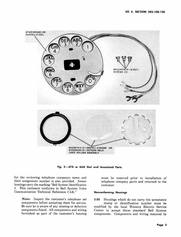
Fig. 2m6TA or 6UA Dial and Associated Parts
for the reviewing telephone companys name and must be removed prior to installation of
their assignment number is also provided. Newer telephone company parts and returned to thehousings carry the marking "Bell System Identification customer.#. This enclosure conforms to Bell System Voice
Communication Technical Reference CAK." Nonconforming Housings
Note: Inspect the customer's telephone set 3.03 Housings which do not carry the acceptancecomponents before accepting them for service, stamp or identification number must beBe sure he is aware of any missing or defective modified by the local Western Electric Service
components found. All components and wiring Center to accept these standard Bell System
furnished as part of the customer's housing components. Components and wiring removed by
Page 3

SECTION 503-100-120
the service center should be returned to the 3.06 TOUCH-TONE Dial (D-180460 Kitcustomer, of Parts), ordered separately.
Assembly (Desk Set Type) (1) When the customer's antique-decorator housingis intended to be used with TOUCH-TONE
3.04 Install 581A Telephone Set Base as service, install a D-180460 Kit of Parts.follows.
(2) Refer to Table B for dial connections.(1) Remove upper housing from base of
customer-owned housing. 3.07 If a polarity guard is required in conjunctionwith a 35Y3A TOUCH-TONE dial, install a
(2) Position 581A telephone set base on base D-180461 guard assembly, which consists of guard
of customer's housing, ensuring that the assembly, brackets, screws, and a printed wiringringer volume control is accessible through opening board assembly. The polarity guard is installedof base. when specified by local instructions for end-to-end
signaling purposes when battery and ground reversals(3) Fasten 581A base using four screws, furnished are encountered. Refer to Fig. 4 for location and
with set or screws furnished with the Table C for connections.
housing. A typical installation in a customer-owned
desk set type housing is shown in Fig. 3. 3.08 Mounting cord (ordered separateIy)and modular jack using a D-180778
3.05 Rotary Dial (ordered separately). Kit of Parts.
(1) Install 6TA (chrome) or 6UA (gold) dial
(Fig. 2) using three screws furnished with _'_n_ New 581A bases come equipped with
dial. _ a 623P4 mounting cord jack.(2) Refer to Table A for dial connections.
l-
\
4 4 7 _ i,
TI TRANSMITTER
.Fig. 3--Typical Installation, Desk Set Antique--Decorator Housing
Page 4
ISS 4, SECTION 503-100-120
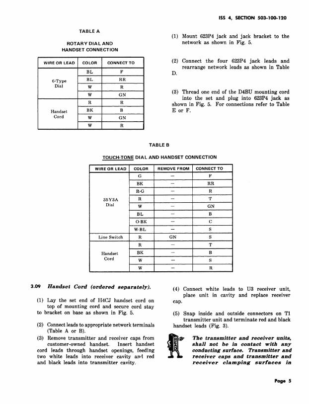
TABLE A(1) Mount 623P4 jack and jack bracket to the
ROTARY DIAL AND network as shown in Fig. 5.HANDSET CONNECTION
WIREOR LEAD COLOR CONNECT TO (2) Connect the four 623P4 jack leads andrearrange network leads as shown in Table
BL F D.
6-Type BL RRDial W R
W GN (3) Thread one end of the D4BU mounting cordinto the set and plug into 623P4 jack as
R R shown in Fig. 5. For connections refer to TableHandset BK B E or F.
Cord W GN
W R
TABLE B
TOUCH-TONE DIAL AND HANDSET CONNECTION
WIREOR LEAD COLOR REMOVEFROM CONNECTTO_
G -- F
BK -- RR
R-G -- R
35Y3A R -- T
Dial W -- GN
BL -- B
O-BK -- C
W-BL -- S
Line Switch R GN S
R -- T
Handset BK -- BCord W - s
w - R
3.09 Handset Cord (ordered separately). (4) Connect white leads to U3 receiver unit,place unit in cavity and replace receiver
(1) Lay the set end of H4CJ handset cord on cap.top of mounting cord and secure cord stay
to bracket on base as shown in Fig. 5. (5) Snap inside and outside connectors on T1transmitter unit and terminate red and black
(2) Connect leads to appropriate network terminals handset leads (Fig. 3).(Table A or B).
(3) Remove transmitter and receiver caps from _g_ The transmitter and receiver units,
customer-owned handset. Insert handset _ shah not be in contact with anycord leads through handset openings, feeding conducting surfaee. Transmitter andtwo white leads into receiver cavity and red reeeiver caps and transmitter andand black leads into transmitter cavity, receiver elampinK surfaces in
Page 5
SECTION 503-100-120
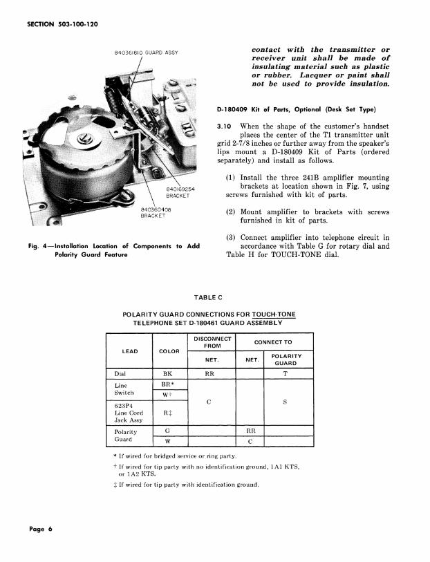
840561810GUARDASSY contact with the transmitter orreceiver unit shall be made of
insulating material such as plasticor rubber. Lacquer or paint shallnot be used to provide insulation.
D-180409 Kit of Parts, Optional (Desk Set Type)
$!_i_:ii!iii 3.10 When the shape of the customer's handset
_4 places the center of the T1 transmitter unit.... grid 2-7/8 inches or further away from the speaker's
lips mount a D-180409 Kit of Parts (ordered.... separately) and install as follows.
(1) Install the three 241B amplifier mounting
840169254 brackets at location shown in Fig. 7, usingBRACKET screws furnished with kit of parts.
840:560408 (2) Mount amplifier to brackets with screwsBRACKET furnished in kit of parts.
(3) Connect amplifier into telephone circuit inFig. 4--Installation Location of Components to Add accordance with Table G for rotary dial and
Polarity Guard Feature Table H for TOUCH-TONE dial.
TAB LE C
POLARITY GUARD CONNECTIONS FOR TOUCH-TONETELEPHONE SET D-180461 GUARD ASSEMBLY
DISCONNECT CONNECTTOFROMLEAD COLOR
POLARITYNET. NET. GUARD
Dial BK RR T
Line BR*
Switch W+
623P4 C SLine Cord R:_Jack Assy
..........
Polarity G RR
Guard W C
* If wired for bridged service or ring party.
+ If wired for tip party with no identification ground, 1A1 KTS,or 1A2 KTS.
:_If wired for tip party with identification ground.
Page 6

ISS 4, SECTION 503-100-120
HANDSET CORD
MOUNTING
CORD
HANDSET
CORD STAY
.......
6234P JACK
Fig. 5mlnstallation of Mounting Cord Using D-180778 Kit of Parts
Assembly (CandIestick Type) 3.'12 Install 581A Telephone Set Base asfollows.
3.1 | Convert customer's candlestick housing
as follows. (1) Remove line switch from 581A base (currentmodel only).
(1) Remove four mounting screws which secures
baseplate to candlestick housing. (2) Remove square snap-in cover from bottomof candlestick mounting base.
(2) Remove dial bracket retaining screw from
elongated hole in baseplate. (3) Mount line switch to customer's set withactuator toward terminal board.
(3) Lift off dial mounting plate and remove
dummy dial by removing two screws. (4) A typical installation of a candlestick typetelephone set is shown in Fig. 6.
(4) See 3.13 for 6-type dial installation procedures.
(5) If 581A base (subset) is wall mounted, adjust(5) Remove dummy handset cord from base. ringer volume control to "LOUD" before
attaching subset to wall.(6) See 3.15 for handset cord installation
procedures. _ When 581A base is mounted on a wall
f&or other vertical surface, the baseshould be flush against sur£aee £or
Note: When disassembling transmitter housing proper operation o£ PIA ringer.avoid grasping the horn. When reassembling,
make sure nut at pivot point is properly (6) See 3.14 for mounting cord installationkeyed, procedures.
Page 7

SECTION 503-100-120
\
/ X_
', )-/
/
H4CJ (1_
HANDSET CORD "lIm
LEADS FURNISHED
WITH PARTS GROUP _ 581ATELEPHONE SET
u 840151054 (FIG. I ) // -._.._ BASE (LESS LINE SW)I
"_.. MOUNT IN SUBSET
\ _ DSBN MTG CORDL _ /_/_,,, OR INSIDE WIRE ". L/. "
_ / "/_' COY ER ( SU PPLI ED\" "_._ __.._TE MINAL BOA D BY CUSTOMER)
LINE SWITCH (REMOVED \ _ _ _ "',..L/_ / (SUPPLIED BY CUSTOMER)FROM 581A BASE ) _......-I
Fig. 6--Typical Installation of Candlestick Type Telephone Set
840560408 3.13 Rotary Dial (ordered separately).
"<:_ ...... ::z::. AM IFIER (1) Install 6TA (chrome) or 6UA (gold) dialz/ss_:_ii!::_._:_::_:,::::_::............... __ (Fig. 2) using three screws furnished with
" :.......................i ':'_:. ".... _j,_ (2) Conneet dial leads to terminal bloek furnishedwithcustomer's desk stand set as shown in
Fi .17.__ 3.14 Mounting Cords (ordered separately).
(1) A standard D3BN mounting cord is requiredfor connections between the line wire,
connecting block and the 581A base network840560390 terminals unless inside wire can be terminated
BRACKETS directly in wall mounted subset. A D6AA mountingcord must be used to provide the connectionsbetween the 581A base and customer's desk
Fig. 7--Installation of D-180409 Kit of Parts stand set, except for party line service where a
D10R mounting cord is used when tip partyidentification is required.
Page 8
ISS4, SECTION503-100-120
(2) Install set end of D3BN and D6AA mounting 3.16 Line and Ringer Connections.cords to 581A base, secure cord stay and
route cord as shown in Fig. 5. D6AA cord can (1) For all classes of service refer to Table Elay on top of D3BN cord. or F.
(3) Terminate cord leads at network terminals. (2) The ringer volume control is blocked fromWire connecting block end of D6AA mounting off position by a factory placed stopscrew.
cord to appropriate terminal block terminals To enable ringer cut-off feature, remove screwfurnished with customer's desk stand set (Fig. 17 through access hole in top of ringer gong. Adviseor 18). customer of cut-off position to avoid future service
calls.3.15 Handset Cord (ordered separately).
(3) To permanently silence ringer for all classes(1) Install set end of H4CJ handset cord in of service, refer to Section 501-259-101.
opening located in base of customer's deskstand set housing and secure cord stay to base. 3.17 Disconnection of Customer-Owned
Telephone Set Housings: Disconnected(2) Connect two white leads to terminal block customer-owned telephone set housings should be
located on desk stand base (Fig. 17 or 18). disabled by the removal of all Bell System components.
(3) Remove transmitter and receiver caps fromcustomer-owned set. Insert handset end of
cord through opening in receiver handle and 4. MAINTENANCEterminate two white leads to U3 receiver unit.Insulate and store the red and black handset 4.01 Maintenance is limited to those componentscord leads at the terminal block and receiver installed as part of the telephone set baseunit (Fig. 17). group or listed in the Ordering Guide as replaceable
components. Maintenance of housing, handset,(4) Connect the red and black leads furnished and other customer-owned parts is the responsibility
with 840151054 parts group items 7 and 8, of the customer.(Fig. 1) at terminal block in base of desk standset, extend leads toward transmitter unit.
4.02 Refer to appropriate section for maintenance(5) Snap inside and outside connectors onto T1 covering a particular item such as dials or
transmitter unit and terminate red and black ringers.leads (Fig. 3).
(6) Refer to Read, 3.09 for transmitter and 4.03 Refer to connection figures as an aid inreceiver unit insulation, locating and clearing trouble.
Page 9

SECTION 503-100-120
INSIDE G25-TYPE CONN. D4BU-29WIRE BLK. (NOTE 4) MTG
CORD(NOTE 1)
TIP (G) G _ (G) < ( >
RING (R) R _ (R) ,,,,< >GRD (Y) Y _ (Y) ,,.,< >
(BK) B e (BK) ,,.,< >I I
NOTES:1. NOT FURNISHED WITH TELEPHONESET
BASES, ORDEREDSEPARATELY, SEEORDERINGGUIDE
2. 840401723 INSIDE CONNECTORAND840401781 OUTSIDE CONNECTORWITHSCREWTERRINALS SNAP ONTOTRRTR UNIT
3. PART OF D-180788 KIT OF PARTS
4. IF STATION IS EQUIPPED WITH 548-TYPEJACKS A 1A CONVERTERIS REGUIRED
* INSULATED AND STORED
(R)
(Y)
(BK)
Fig. 8--581A Telephone Set Base With D-180778 Kit of Parts (Rotary Dial, Current Version) (Sheet 1 of 2)
Page 10

ISS 4, SECTION 503-100-120
U3 RCVRLINE NETWORK DIAL UNITSWITCH
L1d
Fe (BL)
(BL)
g \f ]
RCVR
T1 TRMTRUNIT
) TRMTR
c (BR) _K
b_l_ (Y)aT (s) A
(R)
(Y) (_)G _S
(BK) (_L2 (Z) T
Fig. 8--581A Telephone Set Base With D-180778 Kit of Parts (Rotary Dial, Current Version) (Sheet 2 of 2)
Page 11

SECTION 503- 100-120
............ ii!i!i!!!_
.-TY.Eiiii!iiiiiiLE.O iiiiiiiiiii..0,_,062:_:_:_:_i.OlOO..22.-TY.ENETWO.Kiiiii!iiiiii..CJ _ O_.ECE,VE.ON,TDIAL iiiii ASSEMBLIES iili!i LINE SWITCH iliiii iiiiiii!i:::HANDSET i!!i!iii!ii
(NOTE I) iiii!iiiili iiiiiiiiiii iiiiiiiiii! iiiiiiiiiiiiCORD i'iiiiiiilliiiiiiiiiiil(NOTE I} ili!iiiiiil
ii!i!iii!i! !!!!!!!!!ii fl ;!i!;!;!;!;
iiiiiiiiii iiiiiliiii_ ,._, iiiiiiiiiiR iiiiiiii 82461245l iil;i_iii iiii!iiii;i
_l( R_ iiiiiiii 824612451 ii!i;i!ii!i iiiiiiiill iiii;iiiiiii (W) iiiil;iiiil "
iiiiiiiiiii ;iiiil (BL) _ _;_ i_ ( " i;iiiiii_i; iiiii801219320 ii;iilTRMTR
i;i;i;i;i;i il;;i "X" /k i;i;i;iii;i I. !ii;iil;ii!i I iii;i (P-121952) i;ii;i UNTG iiii!ililil 824615548 iiiiiiiiii iiiiiiiiiil] CONN
(2) iiiiiii_i_i (P-46J554) i]iiiiiiiii (R) iiiiiiii!ii! _l I
(_.._._N____ i!iiiiiiiiill IIIiiASSEMBLIESIIIIii'].___ i]iiiiiiiill I (R) i]!i!iiii!i (2) !i]i!]iiiiil(R)/ ;.,, iliiiiiiiii (P-4605521 iiiiiiiiiii (BK) i_i!iiiiiii _ I |-- V_) 9;9;_]! !i!i!;!;!;! ]:i:i:i:]!i! i
iiiiiiii i!iiiiiiiii (._ iiiiiii!i!w ili!il i!iii!iiiiiet iiiiiiiiiii>_ .. iiii iiiiiiiid (_, iiiiiiiiii
-- (2) _iii_i iiiiiiiiiii iiiiiiiiiiii:Z)iiiiiii;iii iiiiliiiiii (BR} iiiiliiiiiii iiiiiiiiiiiiDSBN MOUNTING CORD (NOTE I)
!!iii!i!i!i _!:!:!!!:!:C [____. i:i:i:i:i:i. L2(_//*STRAP I iiiiiiiiiiii
;i;i;iii;i; i;iii;iiiii_ ;iii;iiiiiil i;i;i;iil;i; (G_iiiii iiiiiiiii°-r ,_, iiiiiiiiii!_ ,o.._. i;iiiiiiiill
::::::::::::......
_iiiiiii_iii
......................... ;;ARINGER(NOTE2ANDS) ililili?iiii K_ iiiiiiiiiiii_ooo_ooo,._o_ '"' iiiiii:iiiii !!!!!!!!!!!! '"'.:.:.:,:,:,:iiiiiiiiiiii iiiiiililill:.:.:.:.:.:.
i_i_]_iii;ii iiiiiiiiiiii* K- W- ii!i!!!iii_iG i]ii;ilil]ii (y)
iliiiiiili ;i;i;:...........NOTES:
I. NOT FURNISHED WITH TELEPHONE SET BASES,
ORDERED SEPARATELY, SEE ORDERING GUIDE.
2. WIRED FOR RING PARTY SERVICE.
5. PIA RINGERS MANUFACTURED AFTER 10-1-72
ARE NOT PROVIDED WITH (BL) RINGER LEADS.
")(" INSULATED AN D STORED
4010B NETWORK ONLY
Fig. 9--581A Telephone Set Base and Component Parts, Connections (Rotary Dial, Early Version)
Page 12
ISS 4, SECTION 503-100-120
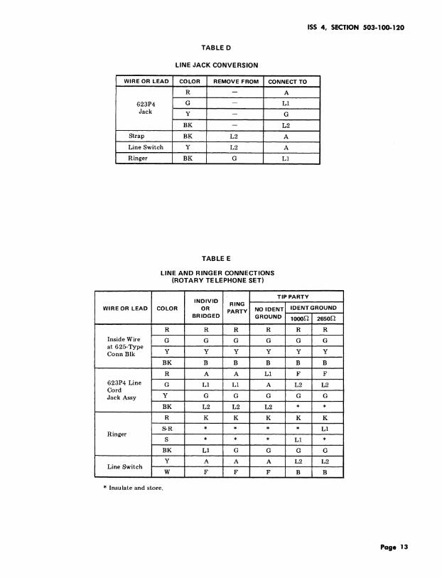
TABLE D
LINE JACK CONVERSION
WIRE OR LEAD COLOR REMOVE FROM CONNECT TO
R -- A
623P4 G -- L1
Jack y _ G
BK -- L2
Strap BK L2 A
Line Switch Y L2 A
Ringer BK G L1l
TABLE E
LINE AND RINGER CONNECTIONS(ROTARY TE LEPHONE SET)
TIP PARTYINDIVID RING
WIRE OR LEAD COLOR OR PARTY NO IDENT IDENT GROUNDBRIDGED GROUND 1000,.Q 2650,Q
R R R R R R
Inside Wire G G G G G Gat 625-TypeConn Blk Y Y Y Y Y Y
BK B B B B B
R A A L1 F F
623P4 Line G L1 L1 A L2 L2Cord ....
Jack Assy Y G G G G G
BK L2 L2 L2 * *
R K K K K K
S-R * * * * L1Ringer
S * * * L1 *
BK L1 G G G G
Y A A A L2 L2Line Switch
W F F F B B
• Insulate and store.
Page 13
SECTION 503-100-120
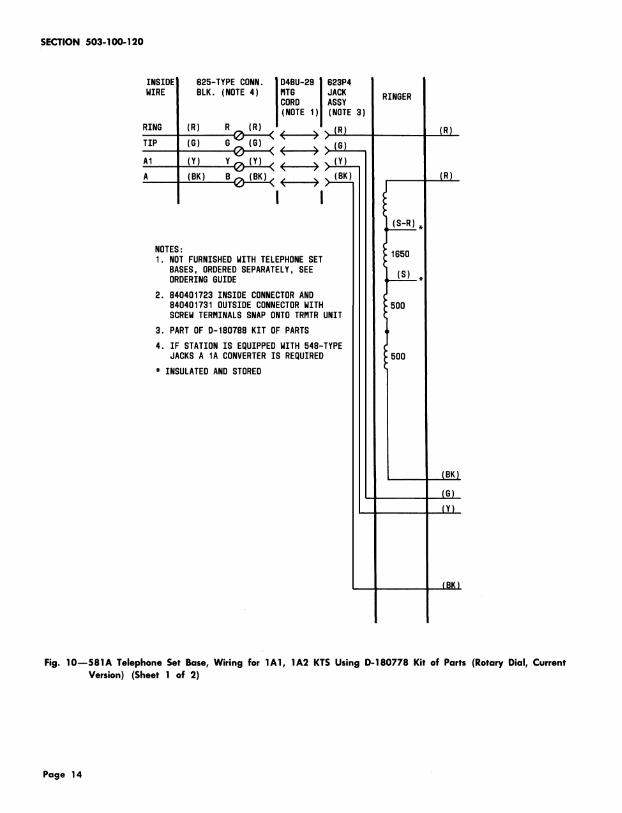
INSIDE 825-TYPE CONN. D4BU-29WIRE BLK. (NOTE 4) RTG
CORD(NOTE 1)
RING (R) R _ (R) _ _ _ (R)
(_( _ _ •TIP (G) G G) < _
A1 (Y) Y _ (Y) < < > (_
A (BK) B _ (BK) _ _ >
I I
NOTES:1. NOT FURNISHED WITH TELEPHONESET
BASES, ORDEREDSEPARATELY, SEEORDERINGGUIDE
2. 840401723 INSIDE CONNECTORAND840401731 OUTSIDE CONNECTORWITHSCREWTERRINALS SNAP ONTOTRRTR UNIT
3. PART OF D-180788 KIT OF PARTS
4. IF STATION IS EQUIPPED WITH 548-TYPEJACKSA 1A CONVERTERIS REQUIRED
* INSULATED AND STORED
Fig. 10--581A Telephone Set Base, Wiring for 1A1, 1A2 KTS Using D-180778 Kit of Parts (Rotary Dial, Current
Version) (Sheet 1 of 2)
Page 14
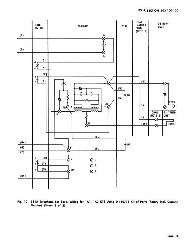
ISS 4, SECTION 503-100-120
U3 RCVRNETNORK DIAL UNIT
(R) A
(R) _ •K
_L \)
RCVR
TI TRMTRUNIT
B TRMTR
(BL)
(BK) _ DP(G) F (BL)(Y)
®s
,2 (2)T(BK)
Fig. 10--581A Telephone Set Base, Wiring for IA1, 1A2 KTS Using D-180778 Kit of Parts (Rotary Dial, CurrentVersion) (Sheet 2 of 2)
Page 15

SECTION 503-100o 120
i::::::::: :]:!:!:!:: _!i_ii_iii iii!i!i!i! i:i:i:i:i:
B-TYPE iiiiiii LEAD i::iii::iiil840151062 iiiiil 4010 OR 4228-TYPE NETWORK !::i::i:i::iiH4CJ ::i::i::::::::i!U3DIAL i::ii:: ASSEMBLIES ::::::i::::::::i::LINE SWITCH ::::::i:: ::i::i::i::i::!HANDSET ::::!::::::::::ii RECEIVER UNIT
(NOTE I)ii::ili::i::i ::i::i::i::iii ::;::?:?:!iii iiiiiiiiiiiI CORD ::i::ili::i::i
i::i::ii::i::i(NOTE I) i::i::i::iii::
!iiiiiiiii iiiiiiiiii (_,iiiiiiiiii!::i::i::;ii::824612451 i::i::;ii::ii ' ;ii!;!i!;i;
R ::i::i::iii::i(P-46J_'45)::i::i::i::i::i (w) iiiiiii G iiilil (W) !i_i
_, ::iiiiiiiii 824612451 iiill i_;i_ii_ii_i_i
/ "_ :::!:!:!:!: (P-46J245) i::i::i::i::i] (W) ::i::::::::::iCa i;ili;i;i; ::;i;i;ili; :_i:ilili:
i iiii' _ (o) Jilili i........... _:;:_:_:_" _(BL'];_-_k:_:_:_:_:_: _;;_I ::::::::i::::::::B0,2,932oii;::;i;ii.....+;...........iiii !ii!iiiii-X- iiilii ::::::i::::::::::iI ::::::i::iii::::(P-121952) i::i::i::;::i::TRMTR
::iii::iii::iI ::i::ii::il CONN ::::::::::::::::::::G i::ii:: B"4615348 _::_::i::!::!:: iii::i::i::::::i :!:!:i:!:! ........... i:i:i:;:i UNiT
!i::i!i::iii(P-46J 534) ::!::i::i::ili (R) ::::i:::::::#: ii::i::iiiil I iiiiii_i_iASS EMBLIES ii!!!i!i!i
iiii::::i!::i! (R) ::::::::::::i::::i i::i::i::i::i::(R)
ca L-r1
i_,i',i'_iiii _,i',i_,'_,i (w) !',!i!!iii i',;ii';; .oo,,_,_ooo_o_i::ii!:::::::::: (NOTES lAND 2)
ii!iii D4BJ iiiiiiilil DIOR iiiii LEAD!iiiii MOUNTING i::!::!i!i!::MOUNTING !::i::i::!i!iiDESIG
ii::i::i::i, CORD ::_::i::i::_ii CORD ii::ii_i_ii!
::i::i_i::i_i ::i_i::i::i::ie i',!i!ii!!!i iiiil;iiii(G) iiiiii_i(W-S) iiiiiii Ti!!iiii!i!i!! i!!!ii!iiiiiiiiid iiiiiiiiiii iiiiiiiiii iliiiiiill (W-DR)iliiii ill T,
W i !ii!i i!!iiii!ii iiii_i!i!iii!
(_ i!i!i!i!i! !!iiiiiiii iiiiiiiiiiiiii!! iiiiiiiii! i!ii_iii (DR-W) i!iiiiiiill R,
1_ :! iiiiill iiiiiiiiiiiBB Ci_i_ _ (G)_ ililiiiii(R) 31_i_i_iiiS-W)iiiiiiiiiiiR
1 _'__ iiiiiiii! (Y) i!iiiiil (W'G)_ iiiiiiiii- A',i_,', iii',;ii', (DR)ii!i!_,',_ii iiiiiil; ',iii_iiii(w-o) iiiiiii;;il AG!iliiii iiiiiiiiii b (Y) !il;iiiiiiii! iiill (BK) i!iiiii!i3i (G-W) iiiiiiiiiil A.
i',iiiiii', iii_iii_i',o-r- (_)iii_i',iii_ o_':c%iiiiiiiiii iiiiiiiiii (O-W) iiiiiiiiiii LK
iiiiiiii;ii !ii!ililil iiiiiiiili (W-BL) iiiiiii!iii P3
..... i .......... . ....... .......
::::::::::: .:.:.:.:.: :::::::::::PIA RI N GER i::!::i::!!!::!- ::::::::::if:::::: iiiiii!iii ( BL- W ) ::!::iii::i::!:: P4
NOTE 4 AN D 5 ) ::!::i::i::::::!! :.i:.ili:.:::::: !!::!::i::!::i ]i_::i::i::i::i
5oo_ 5oo_,6_o_ (R) !/_/_/_ ......
::i!i::::::::::_N0TES ::::::::::::
ili!i!!i!iii!i I. NOT FURNISHED WITH TELEPHONE 4. PIA RINGERS MANUFACTURED_- _ W i::i::::ii:::::::: SET BASES ORDERED SEPARATELY, AFTER I0-1-72 ARE NOT PROVI DED
i!::?:i::i::!:: SEE ORDERING GUIDE. WITH (BE) RINGER LEADS.:::::::::::(BK) i::i::i::ili::i 2. IF ONLY "A" LEAD CONTROL IS 5. WIRED FOR INDIV OR BRIDGED
........... REQUIRED USE A D4BJ MOUNTING RINGING............
:!:!:i:!:!. CORD. IF "A" LEAD PLUS SPEAKER-
iiiiiililil PHONE IS REQUIRED USE A -X" INSULATED AND STORED.
DIOR MOUNTING CORD. + 4010B NETWORK ONLY
3. LEAVE (S) LINE SWITCH LEAD
TERMINI_TED AT L2 WHEN D4BJ
MOUNTII_G CORD IS USED.
Fig. 11--Wiring for 1A1, 1A2 KTS or 3-TyPe (MD) Speakerphone and 1A1, 1A2 KTS (Rotary Dial, EarlyVersion)
Page 16

ISS 4, SECTION 503-100-120
Fig. 12--Wiring for 1A1, 1A2 KTS or 4-Type Speakerphone and 1A1, 1A2 KTS (Rotary Dial)
Page 17

SECTION 503-100-120
INSIDE 625-TYPE CONN. D4BU-29 JMIRE BLK. (NOTE 4) RTG J
CORD I
(NOTE 1)I
TIP (G) R_ (G) < < > (G)
RING (R) G _ (R) ,, (__,, < > (BK)
GRD (Y) Y(_ (Y) _, < >
(BK) B (_ (BK),,.,< )I I
NOTES:I. NOT FURNISHED MITH TELEPHONESET
BASES, ORDEREDSEPARATELY, SEEORDERINGGUIDE
2. 840401723 INSIDE CONNECTORAND840401731 OUTSIDE CONNECTORWITHSCREWTERRINALS SNAP ONTOTRRTRUNIT
3. PART OF D-180788 KIT OF PARTS
4. IF STATION IS EQUIPPED WITH548-TYPE JACKSA 1A CONVERTERISREQUIRED
* INSULATED AND STORED
(Y)
Fig. 13--581A Telephone Set Base Using a D-180778 Kit of Parts (TOUCH-TONE Dial, Current Version) (Sheet1 of 2)
Page 18

ISS 4, SECTION 503-100-120
H4CJLINE NETWORK DIAL HANDSET U3 RCVRSWITCH CORD UNIT
(NOTE1)
(G) L1
(BK) ,_(G)d
e_ (W) _ (G).(BK)m
(BK)
(R-G)
(R) v e
w
x
(BK) (eL)
'_(_R) B( (W)
c (BK
b
A(W)
(R) (O-BK)
(W-BL)(R) K
(Y) G
(8K) L2
Fig. 13--581A Telephone Set Base Using a D-180778 Kit of Parts (TOUCH-TONE Dial, Current Version) (Sheet2 of 2)
Page 19

SECTION 503-100-120
Page 20

ISS 4, SECTION 503-100-120
TABLE F
LINE AND RINGER CONNECTIONS
(TOUCH-TONE TELEPHONE SET)
INDIVID TIP PARTYRaNG ,DENTGROUNOWIREORLEAOCOLOR OR NO,OENTPARTY
B.,oGEo GROUNO1000_2650_' i / , , ,, , , , ,
R R R R R R
InsideWire G G G G G Gat 625-Type ,Conn Blk Y Y Y Y Y Y
.....BK ' B B' B B B
R A A L_ c C623P4 Line G L1 L1 A L2 L2Cord
Jack Assy Y G G G G G....
BK L2 L2 L2 * *
R K K K K K_.
S-R * * * * L1Ringer ....
S * * * L1 *
BK L1 G G G G
Y A A A L2 L2
Line Switch W F F C B BI
BR C C F F F
• Insulate and store.
TABLE H
TABLE G (OPTIONAL) 241B AMPLIFIER CONNECTIONS
(OPTIONAL) 241B AMPLIFIER CONNECTIONS (D-180409 KIT OF PARTS) TOUCH-TONE(D-180409 KIT OF PARTS) ROTARY DIAL DIAL
f ,,,
WIRE CONNECT TO CONNECT TOREMOVE REMOVE
WIRE OR LEAD COLOROR COLOR FROM NET. 241B NET. FROM 241B NET.
LEAD AMPLIFIER AMPL
D-180409 R 4 R D-180409 R 4 RKit ........
of Parts BK 1 B Kit of Parts BK 1 B
H4CJ R R 2 W TB-1 5Handset H4CJ Handset R TB-2 2
Cord BK B 3 Cord (Set End)(Set End) BK B 3
W-BL TB-1 5
35Y3A R TB-2 2
Dial G TB-3 6
BL B 3
R TB-1 5
Line Switch W TB-3 6
Page 21

SECTION 503-100-120
INSIDE G25-TYPE CONN. D4BU-29WIRE BLK. (NOTE 4) RTG
CORD(NOTE 1)
TIP (G) R_ (G) -," ,,,, _, (G)
RING (R) G_ (R) _ _
A1 (Y) Y(2) (Y) _, _
A (8K) B(_ (BK)_, < > (BK)
I I
NOTES:1. NOT FURNISHED WITH TELEPHONESET
BASES, ORDEREDSEPARATELY, SEEORDERINGGUIDE
2. 840401723 INSIDE CONNECTORAND840401731 OUTSIDE CONNECTORWITHSCREWTERRINALS SNAP ONTOTRRTRUNIT
3. PART OF D-180788 KIT OF PARTS
4. IF STATION IS EQUIPPED WITH548-TYPE JACKS A 1A CONVERTERISREQUIRED
* INSULATED AND STORED
(R)
(R)
(Y)
(BK)
Fig. 15--Wiring for IAI, IA2 KTS Using D-180788 Kit of Parts (TOUCH-TONE Dial, Current Version) (Sheet
1 of 2)
Page 22
ISS 4, SECTION 503-100-120
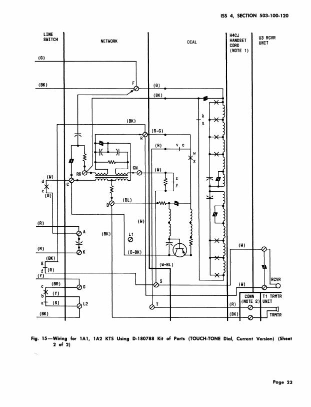
LINE H4CJ U3 RCVRSWITCH NETHORK DIAL HANDSET UNITCORD
(NOTEI)(S)
(BK) F
j,j; _) (G)._ I(BK) _ _ l
- P v I
v
(BK) " : "_ •U
.RJ_ (R-G): v
T _ , _AI- I (R) v e
: _ [ x
(W) R _,_
-(G) ,,
B(), (BL)
(R) (W)
i _A (BK) L1®
"I.. (w)(R) K (O-BK) i(BK) ' ,'_ T. I
_[.. (H-BL) ._ !'(R) <
( i ×fl_,.(o_)I_o , (_)
(BK) (BK)I I TRRiR
Fig. 15--Wiring for 1A1, 1A2 KTS Using D-180788 Kit of Parts (TOUCH-TONE Dial, Current Version) (Sheet2 of 2)
Page 23

Page 24

ISS 4, SECTION 503-100-120
Fig. 17--Candlestick Type Telephone Set Connections (With D6AA Mounting Cord)
Page 25

SECTION 503- ! 00-120
DESK STAND:.:.:.:.:.
_"" "'_ !ii!iiiii!..................
LINE iiiiiiiii 42A iiiii!ii}iD3BN iiiiiiiiii 4010 OR 422e-TYPE NETWORK iiiiiiiiii DIOR !ii!i!!!ii TERM. BLOCK iiiiiiiiii 6-TYPE :}ililiiiii LINE SWITCHWIRE iiiiiiiii CONN i!iii_ii!iHTG CORD(_ES) i;iiiiiiii MTG iiiiiii!ii (FURNISHED BY iiiii!i!il DIAL ...... (NOTE I)
ii_i_iiieLK ii!iiiiiiORINSIDE_ ...............................i:E:i:i:i .......... :::::::::: .......... :!:_:!:i:F ...........:i:i:i:i: iEiEiiiiiiWIRE :::::::::: iiiiiEiiii(NOTE 2 iiiiEiE!!i i_iEii_i :::::::::::iEiiiEiii ii_iEii_Ei iiiiii!iii i!i!i!!i!iAND 6) iiiilM iEi_i_iii" i_iiiiiiiii..................... """.... iiiiiiiiEi!
.................... ::::::::: ::::: :::::- .I.
iiiiiiii: _ii!iii!!_ _i_iCi_! .......... :.................... e.................... •.... ::::: / ......... :::::::
i:_:i:i:: iiii!iiiil iiiiii]i!! !i!i!)!!!i !;!;ii!;!; _ i!ii!ii _:!:i:i:i:iiiiiiiiil iiEEii_E_ iiiilEi!!i !!ii!iii_i(W-G)iii!!i 2 (BK) B_:!i!:.!!ii!i..... .................... :.:.:.:.:. ...........
ii)iiiii)iiiiii!iii il)iii!)(G-w)_;_ (R)ii)_)i)!)i)i)_)_]_) )))))))))).......... :!:!:i:i:iDP i)iii)i)i)i:i:!:i:!........... iiiiiii_ii I R (W-BR) iii!iiiiii_ (BK) !iiiii!ii !;i11_ii_iiEEEEEEEE EEEEEEEEiE .......... ,.... :i!E!)!i!i:
:.:.:.:.: ..................... q :::::: ......
:E:!:E:E: iE!_E_EEEE "-'.'-'.'. :::::::::: :E:E:i:_:E:
................... )i_ii_)_)_ \ )_)_!_i_i_ .....................::::::::: :.:.:.:.:. :::::::::: :::::::::::i_E_i_Ei I!EiEEiEiE :::::::::: :E:E:!:E:E:EiE_IE_EE :E:E:E:E:E :E:i:E:E:E :':':':':':
::::::::: :::::::::: :.:.:.:.:.:::::::::: :::::::::: ....._) ...........
................... "......... _) !N :_:i:I:E:i:
::::::::: :::::::::: .......... ::::::::::.:.:.:.:. :::::::::: :::::::::: ..........E:E:E:E:E :::::::::: :'::':':" ::::::::::::::::::: i:E:E:E:E: iEE!EEiEEi E:E:E:E:E:;:E:E:E:E: :E:E:E:E:E :::::::::: :':':':':::::::::: :::::::::: :::::::::: ::::::::::
................... (BR-W) (W) ..........
...................iiiiiiii iiiii!i))i!)!iii ii!i!iEiii _ iiiiii)ili_ g
i_i_)_)_i _ )i)i))ililc_ i)iii)i! )i)i)'ililI ' _ 'iiiii')ii;.(o)
.......... )))))))))))--i::::::::: ::::::::::ii)i)i[ii i)iiiiiii) )))]))i))) i:E:!:!:!:::::::::: :::::::::: :i:S:E:E:E :E:]:E:E:EE!EEEEEEE E:E:E:E:E: E:E:E:!:!: E:E:E:i:E: j
.......... iiiiiiil:_:_:_:_:B _ (w-s))i)))i!)i) .......... _L)))!)))))_ ))))))))) )i)i))]i)iI _ ;)_);)_)_) lk............................. -_ (BL):i:i:E:E: :!:E:E:E:! i!Ei!EEEE! :E:i:E:E:i
........................ _ ::::: iii)ii_i); c(G) iiiiiiiii G i_i_i::ili.':T'P (G) iiiiiiiill L_ iii!iiii! :!:!:i:i:i :i:!:_:!:!.......... !_!_]:!:! :!:3:!:!:i( - _ iiii))))i! I;)E)E);I)(Y) b
:::::::::!i!ii_i_!_ ::::::::::!!)!!!! iiiiiiEii!iEi!_i G_STRAP'(BK'_" K _/-';'kA i!i!i!i!i!i!i!ii'W-O' iiiiiiiiii:':':':':'i_i_iiiiil i'iiiiiiii::::::::::iiiiEiiiii(S) i)))))))) f(Y) iiiiiiiii GRD (Y) !!!!!!!!!! I _ , !!i! ..........::::::::: .......... :::::::::: ::::::::::
E:!:E:i:E !!iiiii!ii iii)iii................... EEEEEEEiEE Ei_iEiEiEi _!_E!EEEEE!801219320}_:!!!!:_i_iiEiiii .......... EIE)E)E)E) )E)EiE)E)E )i))i)i))i)(P-121932) i)))))TI TRMTR UN IT................... ;iiiEii;ii :!:!:!:!:! _ ili_iiiiiiiCONN ASSY i!i!iiiii]i , .
......... i!iiE_ii]i _ i 1 (BL) iiiiiilili i))!)iil)!
......... i_iiiiiiii i!!_!i!iii I _ iiii)i)i)ii!!!!i!i!i (R) @
)iiiiii)iiiiiiiiiii)ii)iiiiilsooa iiiiil)!il i_i_i_)_i:
))))))i)) )))))))))) )i)))i!i)i ( T ))))))i))i )))))i)))))H4CJ ))i)il:.:.:.:.: :::::::::: :.:.:.:.:. ::::::::::iii))ii_ ii!!))iii) ........... i:_:!:!:i)ii))))ii E)EiE)i)E) E_)E!EE)E) iEEEi)EE!E i))))i)i))iHANDSET !)i))i
:!:i:i:_........... ))))))))) " 1650_ !!!!i!i!ii )ilili)]): ii))iii)i)iCORD ii)))......... _ _ i]iii!!]il :_:_:_:_:_ .........._:_:_:_:_ :_:_:_:_:_ i_i_i_i_i_ ]!iil]!!il iiiii!iiiil(NOTE6) iiii!iiii]iU3 RCVRUNIT
....................:):))):i)i;i;i:);i;_:_:_:_:_ (R) _:::::::::::_:_:_:_:_;m;_;_m_..... ......_!! (w) !)))!!))))i_.i)i)ii))) EEiEEEiEEE ))iiil)))i (NOTE 4 AND 5) )))i)))i)) ))iil))))) )EiE)i)Eii LIE#; (BK):_:_:_:_: )i))iiiiii _:_:_:_:_: * :::::::::: _:_:_:i:i_ _i -x.-ili)i!ii!)i)_!_iC _i_)_!_i_i iiiiii)ii)
NOTES: * INSULATED AND STORED.
I, LINE SWITCH REMOVED FROM 581A TELEPHONE SET BASE NETWORK ONLY
AND INSTALLED IN CUSTOMER-SUPPLIED DESK STAND, DP - DIAL PULSE CONTACT
2. INSULATE AND STORE (S-W) LEAD. ON - DIAL OFF NORMAL CONTACT3. LEADS FURNISHED WITH 840151054 PARTS GROUP.
4. WIRED FOR TIP PARTY SERVICE WITH I O00.Q, IDENT GRD.
5. PIA RINGERS MANUFACTURED AFTER 10-1-72 ARE NOT
PROVIDED WITH {BL) RINGER LEADS.6. NOT FURNISHED WITH TELEPHONE SET BASE, ORDERED
SEPARATELY, SEE ORDERING GUIDE.
Fig. 18mCandlestick Type Telephone Set Connections Wired for Tip Party Identification (With DIOR MountingCord)
Page 26

ISS 4, SECTION 503-100-120
TABLE I
MODIFICATIONS FOR 1A1 OR 1A2 KTS
NET. TERM.
LEAD COLOR REMOVE CONNECTFROM TO
S A L2
Y A L2
Line Switch BR C G
G L1 A
W F C
623P4 Line Cord G L1 FJack Assembly
Ringer BK L1 F
Page 27
27 Pages


![[XLS]test.nhb.org.intest.nhb.org.in/Urban_Housing/4041 statutory Towns.xlsx · Web view502 802681 27 502 802682 27 503 802683 27 503 802684 27 503 802685 27 503 802686 27 503 802687](https://static.fdocuments.in/doc/165x107/5ab1742b7f8b9abc2f8cb599/xlstestnhborg-statutory-townsxlsxweb-view502-802681-27-502-802682-27-503-802683.jpg)
