5011 TO1A TOUCH-A-MATIC TELEPHONE SET, S...
8
BELLSYSTEMPRACTICES SECTION 503-400-200 AT&TCo Standard Issue 2, July 1982 5011 TO1A "TOUCH-A-MATIC*" TELEPHONE SET, S SERIES IDENTIFICATION, INSTALLATION, CONNECTIONS, OPERATION, AND MAINTENANCE 1. GENERAL • Eliminate Fig. 5 1.01 This section contains information on the • Show 5011T01A-51 and 5011T01A-58 manu- TOUCH-A-MATIC telephone, S series 12- facture discontinued (MD)(Table A) button, wall type telephone set (Fig. 1 and 2). • Add emergency symbols (Fig. 2). S Warning: This equipment generates, uses, and san radiate radio frequency i.03 This telephone set can only be used for indi- energy and if not installed and used in vidual or single line TOUCH-TONEr service. accordance with the instructions manual, may cause interference to radio eommu- Note: This set is not designed for speaker- nieations. It has been tested and found to phone, loudspeaker, A lead control, or party line comply with the limits for a Class B eom- service. puting devise pursant to Subpart J of Part 15 of Federal Communications Com- 1.04 The set is available in the colors listed in Table mission (FCC) Rules, which are designed A. The only faceplate color available for the to provide reasonable protection against automatic dialer is silver (-122). such interference when operated in a commercial environment. Operation of 2. IDENTIFICATION this equipment in a residential area is likely toeauseinterfereneein which ease 2.01 The 5011T01A wall telephone set has a 12- the user at his own expense will be re- button automatic dialing feature. The two top quired to take whatever measures may name and number buttons are illuminated by red and be required to correct the interference.4 green light emitting diodes (LEDs). The set also con- tains a TOUCH-TONES telephone dial, tone ringer, 1.O2 The reasons for reissuing this section are and a MIA handset. listed below. Revision arrows are used to em- phasize the more significant changes. 2.02 Design features are as follows: • Include electromagnetic interference warn- • Modular unit. ing notice in compliance with the FCC ruling which requires that a warning statement be • Solid state circuit memory and network. placed in the user's documentation for equip- ment that generates and uses radio fre- • Automatic dialing of 12 stored numbers. quency energy and may radiate that energy, paragraph 1.01 • Will store up to 16 digits per number. • Add information on M2A handset • Capability to record, change, or delete num- bers in memory. • Revise battery replacement information on instruction label (Fig. 4) t Registered Service Mark of American Telephone and Telegraph - Company. * Registered Trademark of American Telephone and Telegraph Company. _:Trademarkof American Telephone and Telegraph Company. NOTICE Not for use or disclosure outside the Bell System except under written agreement Printed in U.S.A. Page 1
Transcript of 5011 TO1A TOUCH-A-MATIC TELEPHONE SET, S...
BELLSYSTEMPRACTICES SECTION503-400-200AT&TCo Standard Issue 2, July 1982
5011 TO1A "TOUCH-A-MATIC*" TELEPHONE SET, S SERIES
IDENTIFICATION, INSTALLATION, CONNECTIONS, OPERATION,
AND MAINTENANCE
1. GENERAL • Eliminate Fig. 5
1.01 This section contains information on the • Show 5011T01A-51 and 5011T01A-58 manu-
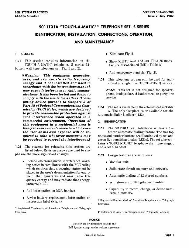
TOUCH-A-MATIC telephone, S series 12- facture discontinued (MD)(Table A)button, wall type telephone set (Fig. 1 and 2).
• Add emergency symbols (Fig. 2).S Warning: This equipment generates,
uses, and san radiate radio frequency i.03 This telephone set can only be used for indi-energy and if not installed and used in vidual or single line TOUCH-TONEr service.accordance with the instructions manual,may cause interference to radio eommu- Note: This set is not designed for speaker-nieations. It has been tested and found to phone, loudspeaker, A lead control, or party line
comply with the limits for a Class B eom- service.puting devise pursant to Subpart J ofPart 15 of Federal Communications Com- 1.04 The set is available in the colors listed in Table
mission (FCC) Rules, which are designed A. The only faceplate color available for theto provide reasonable protection against automatic dialer is silver (-122).such interference when operated in a
commercial environment. Operation of 2. IDENTIFICATIONthis equipment in a residential area islikely toeauseinterfereneein which ease 2.01 The 5011T01A wall telephone set has a 12-the user at his own expense will be re- button automatic dialing feature. The two topquired to take whatever measures may name and number buttons are illuminated by red andbe required to correct the interference.4 green light emitting diodes (LEDs). The set also con-
tains a TOUCH-TONES telephone dial, tone ringer,1.O2 The reasons for reissuing this section are and a MIA handset.
listed below. Revision arrows are used to em-
phasize the more significant changes. 2.02 Design features are as follows:
• Include electromagnetic interference warn- • Modular unit.ing notice in compliance with the FCC rulingwhich requires that a warning statement be • Solid state circuit memory and network.placed in the user's documentation for equip-ment that generates and uses radio fre- • Automatic dialing of 12 stored numbers.
quency energy and may radiate that energy,paragraph 1.01 • Will store up to 16 digits per number.
• Add information on M2A handset • Capability to record, change, or delete num-bers in memory.
• Revise battery replacement information oninstruction label (Fig. 4) t Registered Service Mark of American Telephone and Telegraph
- Company.
* Registered Trademark of American Telephone and TelegraphCompany. _:Trademarkof American Telephone and Telegraph Company.
NOTICENot for use or disclosure outside the
Bell System except under written agreement
Printed in U.S.A. Page 1
SECTION503-400-200
Fig. 1--5011T01A Telephone Set
Page 2

ISS2, SECTION503-400-200
Fig. 2--5011TOIA Telephone Set With Handset, Dialer Faceplate, DirectorSheet, andBattery Removed
• Single button dialing and directory space for • Telephone number recording with handsetnames and numbers, on- or off-hook. Off-hook recording does not
interfere with conversation.
• Two illuminated buttons to highlight impor-tant telephone numbers. • RECORD ON/OFF button protected during
normal usage by faceplate to prevent inad-• M1A handset, vertent erasure of stored numbers.
• Electronic tone ringer. • Built in polarity guard.
• Internal S1 sounder unit which provides 2.03 Operating features are as follows.tones for automatic dialing, indicating
proper recording procedures, and for check- __ This set is not compatible with all
ing the battery. _ facilities due to limited availableloop current, and may not function
• Battery powered repertory dialer, properly in all cases. When thesesets are connected to these facilities,
such as analog subscriber loop car-
Page 3

SECTION503-400-200
tier systems (SLC-1 type, SLC-8 (f) Customer Instruction Booklet, CIB-2506.type) and Iong loops (over 1300ohms), the sets may not dial from the (b) Order the following separately:manual dial keypad. When this in-compatibility is encountered, the • Cord, Handset, H4DU.
customer should be directed to ex- (c) Replaceable components are as follows:change the set for another product.
• Alkaline Battery, 9-volt (customer replace-. 12-button memory field with low force, short ment only)
travel nonlocking buttons.• Handset, MIA- (see Table A for color suffix
• TOUCH-TONE dialing (with short travel or comcode number)buttons).
• Cord, Handset, H4DU- (see Table A for color
• RECORD ON/OFF button, under faceplate, suffix or comcode number)when momentarily depressed places dialer in
the record mode, subsequent operation ter- • Faceplate, 1200A1-122minates the recording mode.
• 841408289 Card Retainer
• Approximately 1 to 1-1/2 minutes automatic• 841408255 Number Card
time-out if left idle in the record mode.
• 841396559 Directory Sheet (double-sided)• Approximately 10 second light time out on
the red and green LED illuminated buttons. • Battery Cover (see Table A for color suffix orcomcode number).
• Normal telephone usage with either the auto-
matic dialer or manual TOUCH-TONE tele- (d) I_Associated apparatus is as follow:phone dial.
(1) Handset, M2A- (see Table A for color suffix
• Tone ringer with slide adjustment for volume or comcode number) (for use with inductivecontrol, pickup hearing aids, refer to Section
501-210-110).i• No provisions have been made in this set de-
sign to provide for ringer cutoff. 3. INSTALLATIONAND CONNECTIONS
2.04 Ordering guide is as follows: Note: Inside wire need not be connected tothe ground terminal at the protector or equiva-
(a) The 5011T01A is a modular type telephone set lent.and may be ordered as follows:
3.01 The telephone set is shipped with a 9-volt al-
(1) Set, Telephone, 5011T01A- (see Table A for kaline battery, to be connected at the time ofcolor suffix or comcode number) includes installation. Remove the battery cover on the rear of
the following: the set and make the necessary connections. Placethe battery in the battery compartment and close the
(a) Faceplate, 1200A1-122 cover (Fig. 3).
(b) Battery, KS-21618L2 (9-volt) Note: The battery should last approximatelyone year under normal telephone usage. All sub-
(c) Handset, MiA- (see Table A for color suf- sequent batteries are to be provided and in-fix or comcode number) stalled by customer. If set is disconnected,
remove and discard the battery.(d) 841386352 Directory Marker (color dots
and emergency symbols) 3.02 A 630-type modular wall connecting blockmust be used to connect the telephone to the
(e) 841396559 Directory Sheet (double-sided) wall.
Page 4
ISS 2, SECTION503-400-200
TABLEA
TELEPHONESETHOUSING, HANDSET CORD, BATTERYCOVER,AND FACEPLATECOLORS
HOUSING,HANDSET HOUSINGANDCORD,ANDBATTERY HANDSETCORD, BATTERYCOVER FACEPLATESUFFIX
COVERCOLOR SUFFIX NUMBERS COLOR
Ivory -50 841411507
Green -51(MD) 841411515
Yellow -56 841411523Silver -122
White -58(MD) 841411531
Brown -104 841411549
Rust -124 841411556
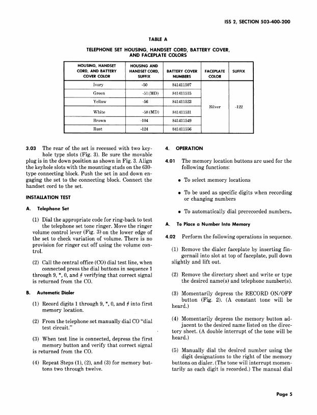
3.03 The rear of the set is recessed with two key- 4. OPERATIONhole type slots (Fig. 3). Be sure the movable
plug is in the down position as shown in Fig. 3. Align 4.01 The memory location buttons are used for the
the keyhole slots with the mounting studs on the 630- following functions:type connecting block. Push the set in and down en-gaging the set to the connecting block. Connect the . To select memory locationshandset cord to the set.
• To be used as specific digits when recordingINSTALLATIONTEST or changing numbers
A. Telephone Set • To automatically dial prerecorded numbers.
(1) Dial the appropriate code for ring-back to testthe telephone set tone ringer. Move the ringer A. To Placea Number Into Memory
volume control lever (Fig. 3) on the lower edge ofthe set to check variation of volume. There is no 4.02 Perform the following operations in sequence.
provision for ringer cut off using the volume con-trol. (1) Remove the dialer faceplate by inserting fin-
gernail into slot at top of faceplate, pull down
(2) Call the central office (CO) dial test line, when slightly and lift out.connected press the dial buttons in sequence 1
through 9, *, 0, and # verifying that correct signal (2) Remove the directory sheet and write or typeis returned from the CO. the desired name(s) and telephone number(s).
B. AutomaticDialer (3) Momentarily depress the RECORD ON/OFFbutton (Fig. 2). (A constant tone will be
(1) Record digits 1 through 9, *, 0, and # into first heard.)memory location.
(2) From the telephone set manually dial CO "dial (4) Momentarily depress the memory button ad-test circuit." jacent to the desired name listed on the direc-
, tory sheet. (A double interrupt of the tone will be
(3) When test line is connected, depress the first heard.)memory button and verify that correct signal
is returned from the CO. (5) Manually dial the desired number using thedigit designations to the right of the memory
(4) Repeat Steps (1), (2), and (3) for memory but- buttons on dialer. (The tone will interrupt momen-tons two through twelve, tarily as each digit is recorded.) The manual dial
Page 5
SECTION503-400-200
Fig. 3m5011T01A Telephone Set, Bottom View
Page 6
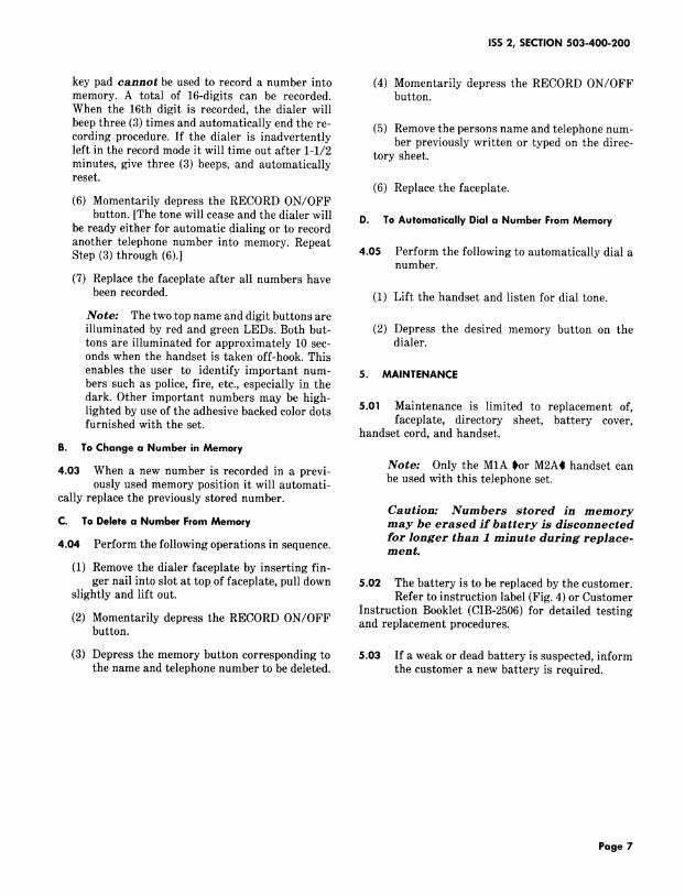
ISS 2, SECTION503-400-200
key pad cannot be used to record a number into (4) Momentarily depress the RECORD ON/OFFmemory. A total of 16-digits can be recorded, button.When the 16th digit is recorded, the dialer will
beep three (3) times and automatically end the re- (5) Remove the persons name and telephone num-
cording procedure. If the dialer is inadvertently ber previously written or typed on the direc-left in the record mode it will time out after 1-1/2 tory sheet.minutes, give three (3) beeps, and automaticallyreset.
(6) Replace the faceplate.(6) Momentarily depress the RECORD ON/OFF
button. [The tone will cease and the dialer will D. To Automatically Dial a Number From Memorybe ready either for automatic dialing or to record
another telephone number into memory. RepeatStep (3) through (6).] 4.05 Perform the following to automatically dial a
number.
(7) Replace the faceplate after all numbers have
been recorded. (1) Lift the handset and listen for dial tone.
Note: The two top name and digit buttons areilluminated by red and green LEDs. Both but- (2) Depress the desired memory button on the
tons are illuminated for approximately 10 sec- dialer.onds when the handset is taken off-hook. This
enables the user to identify important num- 5. MAINTENANCEbers such as police, fire, etc., especially in thedark. Other important numbers may be high-lighted by use of the adhesive backed color dots 5.01 Maintenance is limited to replacement of,
faceplate, directory sheet, battery cover,furnished with the set. handset cord, and handset.
B. To Change a Number in Memory
Note: Only the M1A _or M2A4 handset can4.03 When a new number is recorded in a previ-
ously used memory position it will automati- be used with this telephone set.cally replace the previously stored number.
Caution: Numbers stored in memoryC. To Delete a Number From Memory may be erased if battery is disconnected
for longer than I minute during replace-4.04 Perform the following operations in sequence, ment.
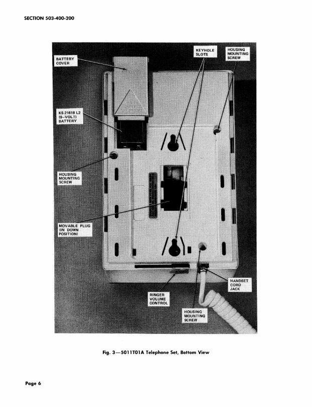
(1) Remove the dialer faceplate by inserting fin-
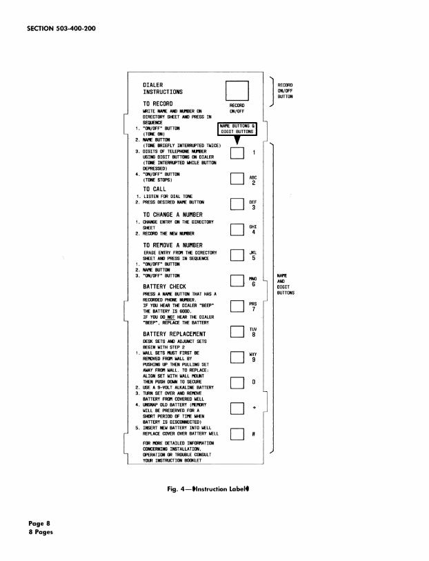
ger nail into slot at topof faceplate, pull down 5.02 The battery is to be replaced by the customer.slightly and lift out. Refer to instruction label (Fig. 4) or Customer
Instruction Booklet (CIB-2506) for detailed testing(2) Momentarily depress the RECORD ON/OFF and replacement procedures.
button.
(3) Depress the memory button corresponding to 5.03 If a weak or dead battery is suspected, inform
the name and telephone number to be deleted, the customer a new battery is required.
Page 7
SECTION 503-400-200
O,,LE. I t I EOROINSTRUCTIONS ON/OFFBUTTON
TO RECORD RECORDMRITENAREANGNDRBERON ON/OFFDIRECTORYSHEETANDPRESSTNSEQUENCE
1. "ON/OFF"BUTTON I NAHEBUTTONSGI(TONEON) DIGIT BUTTONS2. NAREBUTTON •IF
(TONEBRIEFLY INTERRUPTEDTMICE)
3. DIGITS OF TELEPHONENURBER J J 1USINGDIGIT BUTTONSONDIALER I I(TONEINTERRUPTEDMHILEBUTTONDEPRESSED)
4. "ON/OFF"BUTTON _ _C(TONESTOPS) A
TO CALL1. LISTEN FORDEALTONE
2. PRESSDESIREDNAREBUTTON _ D_F
TO CHANGE A NUHBER1. CHANGEENTRYONTHE DIRECTORY
TO REMOVE A NUHBER
ERASEENTRYFRORTHEDIRECTORY _--_ _L.... SHEETANOPRESSIN SEQUENCE1. "ON/OFF"BUTTON2. NAREBUTTON
BATTERY CHECK DIGITPRESSA NAREBUTTONTHATHASA BUTTONSRECORDEDPHONENGRBER.
I IF YOUHEARTHEDIALER"BEEP" r-_ P_S
THEBATTERYIS GOOD.IF YOUDONOTHEARTHEDIALER"BEEP", REPLACETHE BATTERY
r-1BATTERY REPLACEHENTDESKSETSANDADJUNCTSETSBEGINWITH STEP2
1. MALLSETSRUSTFIRSTBE _--1 M_YREROVEDFROflMALLBYPUSHINGUP THENPULLINGSETAMAYFRORMALL. TO REPLACE:
ALIGNSET MITH MALLROUNT _THENPUSHDOMNTO SECURE I _ 0
2. USE A 9-VOLT ALKALINEBATTERY i i
3. TURNSET OVERANDREROVEBATTERYFRORCOVEREDNELL
4. UNSNAPOLDBATTERY(RERORY _MILL BE PRESERVEDFORA I ISHORTPERIODOF TIRE MHENBATTERYIS DISCONNECTED)
5. INSERTNEMBATTERYINTO NELL
_,,_,c_cow_ov_.,._ _,_, I ICONCERNINGINSTALLATION,
OPERATIONORTROUBLECONSULTYOURINSTRUCTIONBOOKLET
Fig. 4--1Hnstruction Label(I
Page 8
8 Pages