
5100 Installation Manual - Jabiru Pacific · INSTALLATION MANUAL FOR JABIRU 5100 AIRCRAFT ENGINE...
24
INSTALLATION MANUAL FOR JABIRU 5100 AIRCRAFT ENGINE This Manual has been prepared as a guide to correctly install the Jabiru 5100 engine into an airframe. Should you have any questions or doubts about the contents of this manual, please contact your supplier.
Transcript of 5100 Installation Manual - Jabiru Pacific · INSTALLATION MANUAL FOR JABIRU 5100 AIRCRAFT ENGINE...
INSTALLATION MANUAL FOR
JABIRU 5100 AIRCRAFT ENGINE
This Manual has been prepared as a guide to correctly install the Jabiru 5100 engine into an airframe. Should you have any questions or doubts about the contents of this manual, please contact your supplier.
REVISION 1 Dated : 1/12/03 Page: 1
1.0 DESCRIPTION ______________________________________________________ 2
2.0 SPECIFICATIONS ___________________________________________________ 2
3.0 DIMENSIONS _______________________________________________________ 3
4.0 DENOMINATION OF CYLINDERS_____________________________________ 4
5.0 ENGINE MOUNT ____________________________________________________ 5
6.0 THROTTLE AND CHOKE_____________________________________________ 7
7.0 INSTRUMENTS _____________________________________________________ 7
8.0 ELECTRICAL EQUIPMENT__________________________________________ 12
9.0 FUEL SUPPLY SYSTEM _____________________________________________ 16
10.0 AIR INTAKE SYSTEM _____________________________________________ 17
11.0 EXHAUST SYSTEM _______________________________________________ 19
12.0 COOLING SYSTEMS ______________________________________________ 19
13.0 PROPELLER SELECTION _________________________________________ 20
14.0 AUXILIARY UNITS________________________________________________ 20
Appendix A ______________________________________________________________ 22
���������������
REVISION 1 Dated : 1/12/03 Page: 2
� � ����������
- 4 Stroke - 8 Cylinder Horizontally Opposed - 1 Central Camshaft - Push Rods - Over Head Valves (OHV) - Ram Air Cooled - Wet Sump Lubrication - Direct Propeller Drive - Dual Transistorised Magneto Ignition - Integrated AC Generator - Electric Starter - Mechanical Fuel Pump - Naturally Aspirated – 2 Pressure Compensating Carburettor - 18 Bearing Crankshaft � � ������������
- Rated Horsepower (cont) : 180 hp @ 3000rpm - Displacement : 5077cc - Bore : 97.5 mm - Stroke : 85 mm - Compression Ratio : 8.5:1 - Direction of Rotation
of Prop Shaft : Clockwise – Pilot’s view – Tractor Applications - Ramp Weight : 117 kg (257 lbs) Complete including Exhaust, Carburettor, Starter Motor, Alternator & Ignition System. - Ignition Timing : 25o BTDC - Firing Order : 1 – 5 – 8 – 3 – 2 – 6 – 7 – 4 - DC Output : 25 Amps - Fuel : AVGAS 100LL and AVGAS 100/130 - Oil : Aero Oil as recommended for your specific climate by your oil supplier. No fully synthetic oils are to be used. - Oil Capacity : 4.0 L min 5.5 L max - Spark Plugs : NGK D9EA
REVISION 1 Dated : 1/12/03 Page: 3
� � ���������
REVISION 1 Dated : 1/12/03 Page: 4
� � ���������������������
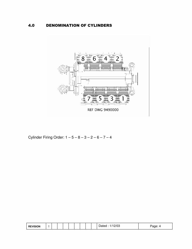
Cylinder Firing Order: 1 – 5 – 8 – 3 – 2 – 6 – 7 – 4
REVISION 1 Dated : 1/12/03 Page: 5
� � ����������
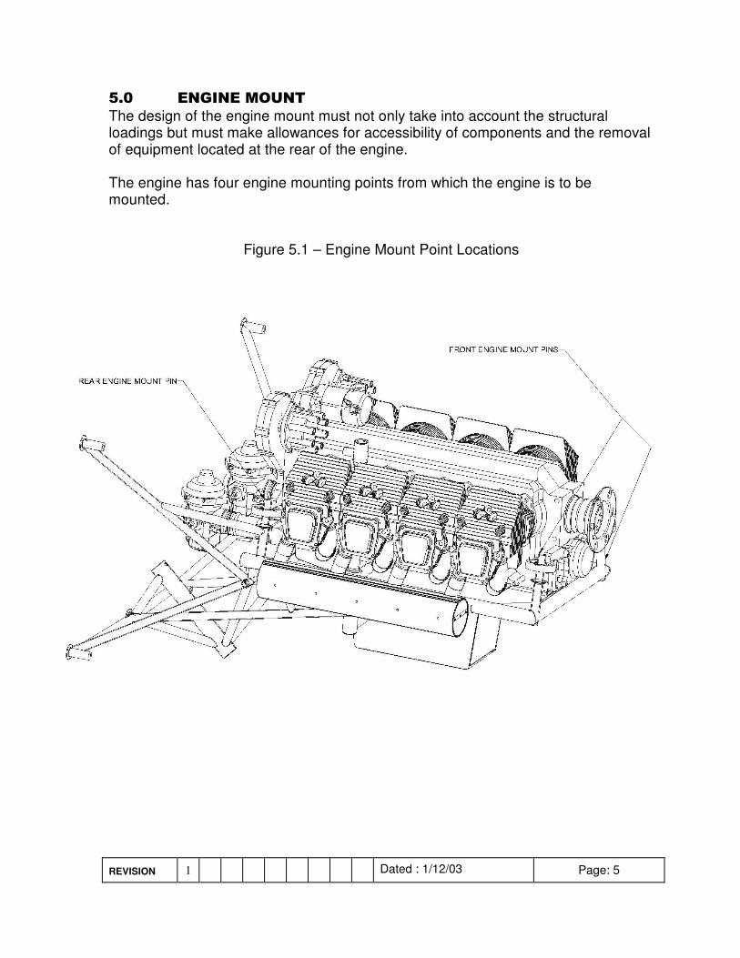
The design of the engine mount must not only take into account the structural loadings but must make allowances for accessibility of components and the removal of equipment located at the rear of the engine. The engine has four engine mounting points from which the engine is to be mounted.
Figure 5.1 – Engine Mount Point Locations
REVISION 1 Dated : 1/12/03 Page: 6
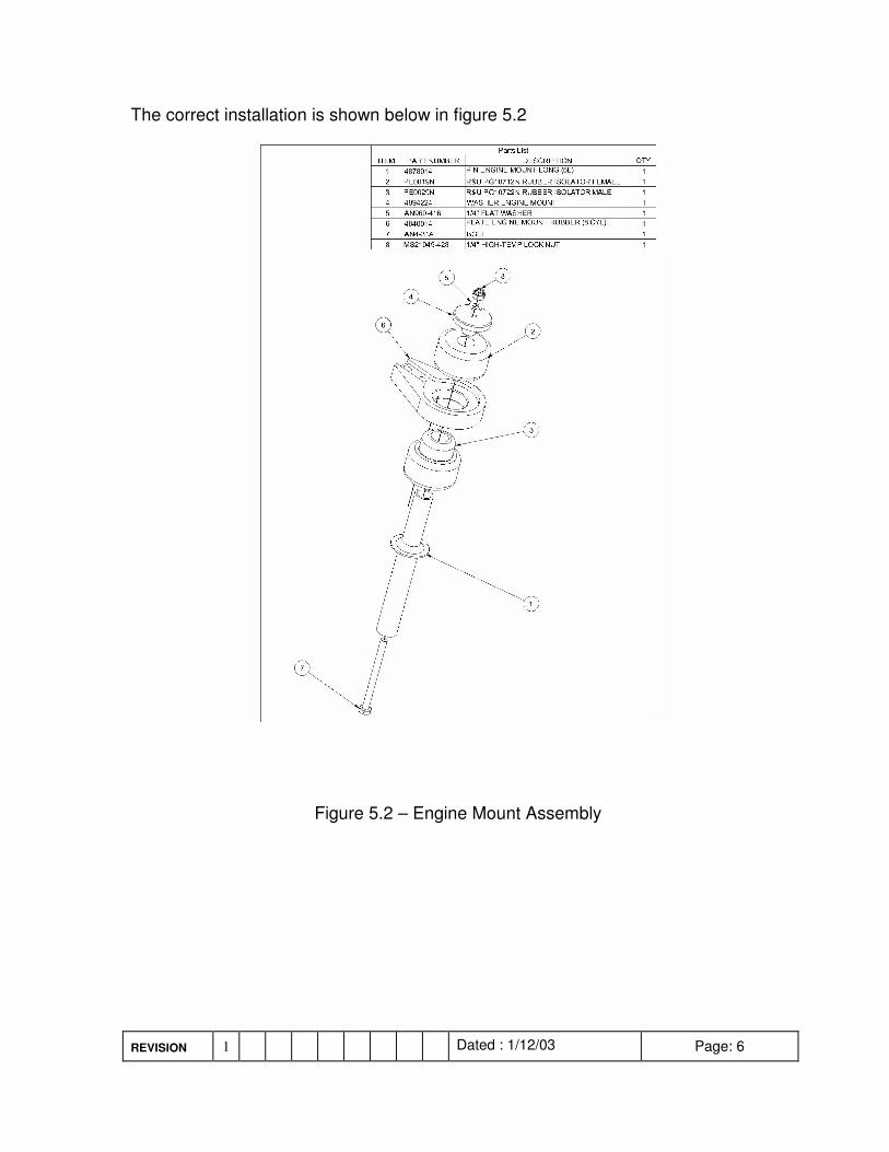
The correct installation is shown below in figure 5.2
Figure 5.2 – Engine Mount Assembly
REVISION 1 Dated : 1/12/03 Page: 7
� � �����������������
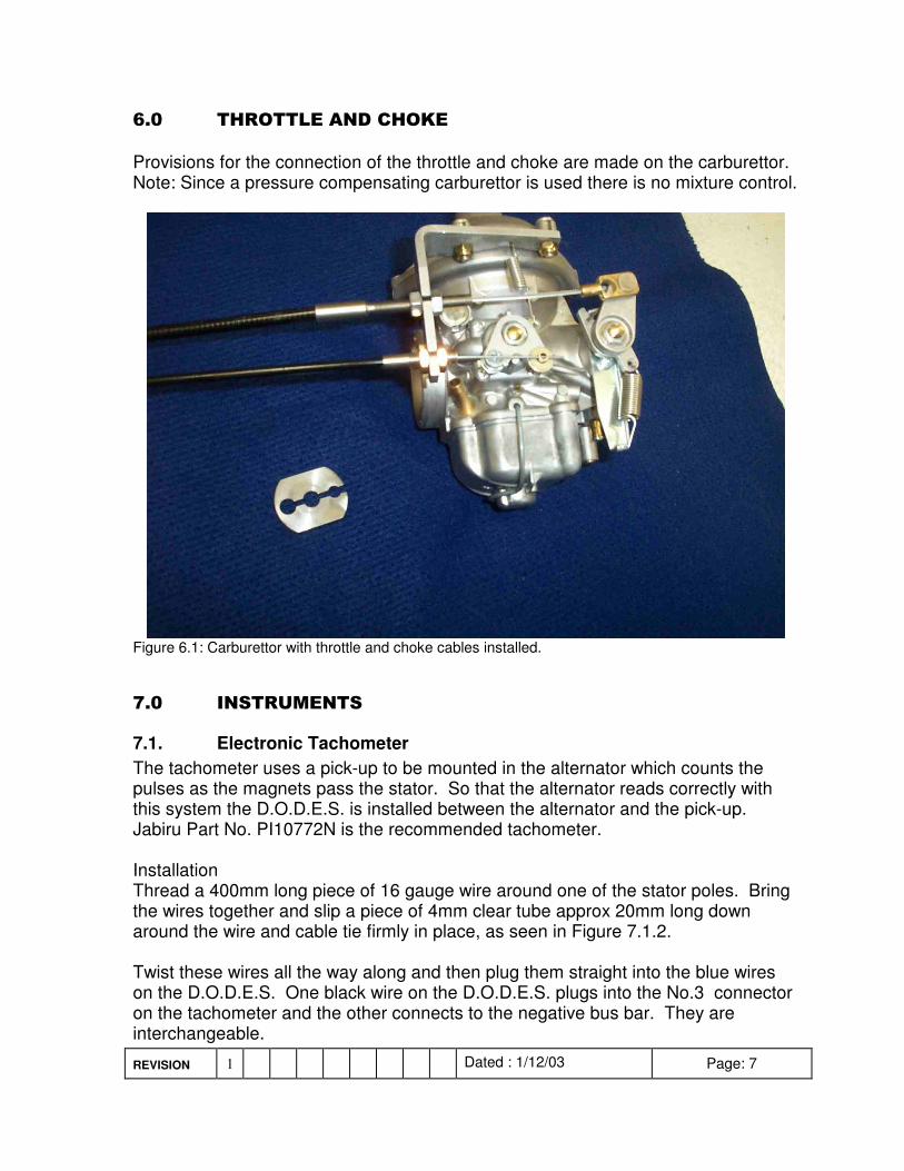
Provisions for the connection of the throttle and choke are made on the carburettor. Note: Since a pressure compensating carburettor is used there is no mixture control.
Figure 6.1: Carburettor with throttle and choke cables installed. � � ����������
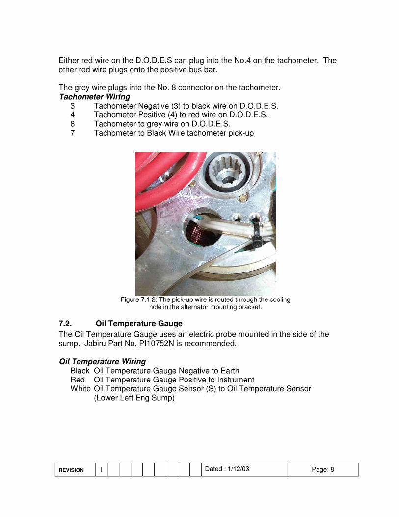
7.1. Electronic Tachometer The tachometer uses a pick-up to be mounted in the alternator which counts the pulses as the magnets pass the stator. So that the alternator reads correctly with this system the D.O.D.E.S. is installed between the alternator and the pick-up. Jabiru Part No. PI10772N is the recommended tachometer. Installation Thread a 400mm long piece of 16 gauge wire around one of the stator poles. Bring the wires together and slip a piece of 4mm clear tube approx 20mm long down around the wire and cable tie firmly in place, as seen in Figure 7.1.2. Twist these wires all the way along and then plug them straight into the blue wires on the D.O.D.E.S. One black wire on the D.O.D.E.S. plugs into the No.3 connector on the tachometer and the other connects to the negative bus bar. They are interchangeable.
REVISION 1 Dated : 1/12/03 Page: 8
Either red wire on the D.O.D.E.S can plug into the No.4 on the tachometer. The other red wire plugs onto the positive bus bar. The grey wire plugs into the No. 8 connector on the tachometer. Tachometer Wiring 3 Tachometer Negative (3) to black wire on D.O.D.E.S. 4 Tachometer Positive (4) to red wire on D.O.D.E.S. 8 Tachometer to grey wire on D.O.D.E.S. 7 Tachometer to Black Wire tachometer pick-up
Figure 7.1.2: The pick-up wire is routed through the cooling
hole in the alternator mounting bracket.
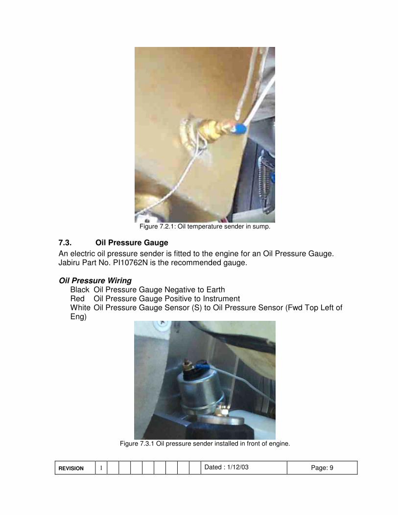
7.2. Oil Temperature Gauge The Oil Temperature Gauge uses an electric probe mounted in the side of the sump. Jabiru Part No. PI10752N is recommended. Oil Temperature Wiring Black Oil Temperature Gauge Negative to Earth Red Oil Temperature Gauge Positive to Instrument White Oil Temperature Gauge Sensor (S) to Oil Temperature Sensor (Lower Left Eng Sump)
REVISION 1 Dated : 1/12/03 Page: 9
Figure 7.2.1: Oil temperature sender in sump.
7.3. Oil Pressure Gauge An electric oil pressure sender is fitted to the engine for an Oil Pressure Gauge. Jabiru Part No. PI10762N is the recommended gauge. Oil Pressure Wiring Black Oil Pressure Gauge Negative to Earth Red Oil Pressure Gauge Positive to Instrument White Oil Pressure Gauge Sensor (S) to Oil Pressure Sensor (Fwd Top Left of
Eng)
Figure 7.3.1 Oil pressure sender installed in front of engine.
REVISION 1 Dated : 1/12/03 Page: 10
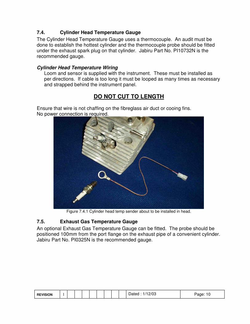
7.4. Cylinder Head Temperature Gauge The Cylinder Head Temperature Gauge uses a thermocouple. An audit must be done to establish the hottest cylinder and the thermocouple probe should be fitted under the exhaust spark plug on that cylinder. Jabiru Part No. PI10732N is the recommended gauge. Cylinder Head Temperature Wiring
Loom and sensor is supplied with the instrument. These must be installed as per directions. If cable is too long it must be looped as many times as necessary and strapped behind the instrument panel.
DO NOT CUT TO LENGTH Ensure that wire is not chaffing on the fibreglass air duct or cooing fins. No power connection is required.
Figure 7.4.1 Cylinder head temp sender about to be installed in head.
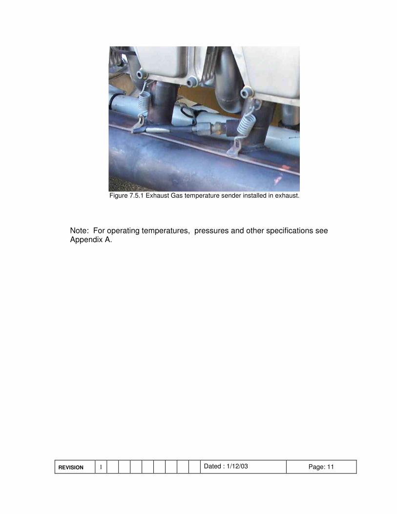
7.5. Exhaust Gas Temperature Gauge An optional Exhaust Gas Temperature Gauge can be fitted. The probe should be positioned 100mm from the port flange on the exhaust pipe of a convenient cylinder. Jabiru Part No. PI0325N is the recommended gauge.
REVISION 1 Dated : 1/12/03 Page: 11
Figure 7.5.1 Exhaust Gas temperature sender installed in exhaust.
Note: For operating temperatures, pressures and other specifications see Appendix A.
REVISION 1 Dated : 1/12/03 Page: 12
� � ���������� �������
8.1. Alternator The rotor is mounted on the flywheel with the stator mounted on the alternator mount plate at the back of the engine. The alternator mount plate is also the mount for the ignition coils and the vacuum pump. Note: The electrical system is Negative Earth.
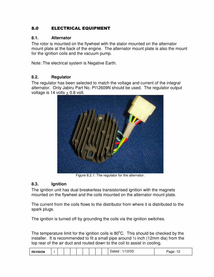
8.2. Regulator The regulator has been selected to match the voltage and current of the integral alternator. Only Jabiru Part No. PI12609N should be used. The regulator output voltage is 14 volts + 0.8 volt.
Figure 8.2.1: The regulator for the alternator.
8.3. Ignition The ignition unit has dual breakerless transistorised ignition with the magnets mounted on the flywheel and the coils mounted on the alternator mount plate. The current from the coils flows to the distributor from where it is distributed to the spark plugs. The ignition is turned off by grounding the coils via the ignition switches. The temperature limit for the ignition coils is 80oC. This should be checked by the installer. It is recommended to fit a small pipe around ½ inch (12mm dia) from the top rear of the air duct and routed down to the coil to assist in cooling.
REVISION 1 Dated : 1/12/03 Page: 13
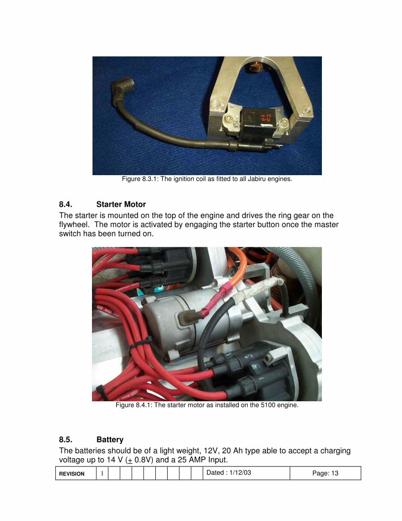
Figure 8.3.1: The ignition coil as fitted to all Jabiru engines.
8.4. Starter Motor The starter is mounted on the top of the engine and drives the ring gear on the flywheel. The motor is activated by engaging the starter button once the master switch has been turned on.
Figure 8.4.1: The starter motor as installed on the 5100 engine.
8.5. Battery The batteries should be of a light weight, 12V, 20 Ah type able to accept a charging voltage up to 14 V (+ 0.8V) and a 25 AMP Input.
REVISION 1 Dated : 1/12/03 Page: 14
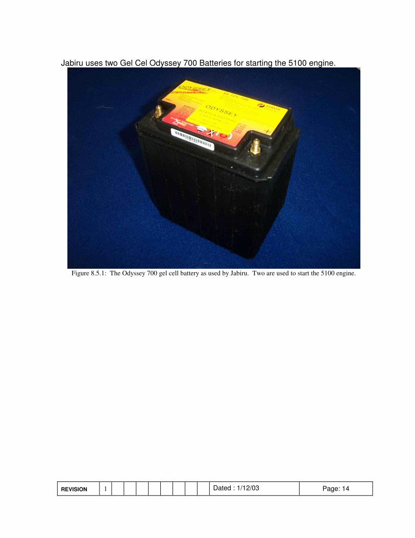
Jabiru uses two Gel Cel Odyssey 700 Batteries for starting the 5100 engine.
�Figure 8.5.1: The Odyssey 700 gel cell battery as used by Jabiru. Two are used to start the 5100 engine.
REVISION 1 Dated : 1/12/03 Page: 15
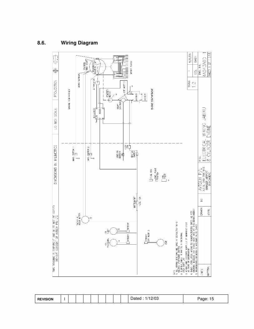
8.6. Wiring Diagram
REVISION 1 Dated : 1/12/03 Page: 16
! � ������������������ �
9.1. Fuel Filtration A Fuel Filter capable of flowing a minimum of 80 ltrs an hour is required. The filter must be present in the system for the fuel flow test. The size of the filter should give consideration to allow adequate flow with a used filter.
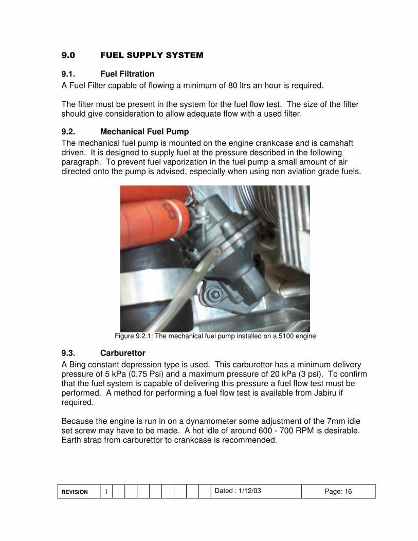
9.2. Mechanical Fuel Pump The mechanical fuel pump is mounted on the engine crankcase and is camshaft driven. It is designed to supply fuel at the pressure described in the following paragraph. To prevent fuel vaporization in the fuel pump a small amount of air directed onto the pump is advised, especially when using non aviation grade fuels.
Figure 9.2.1: The mechanical fuel pump installed on a 5100 engine
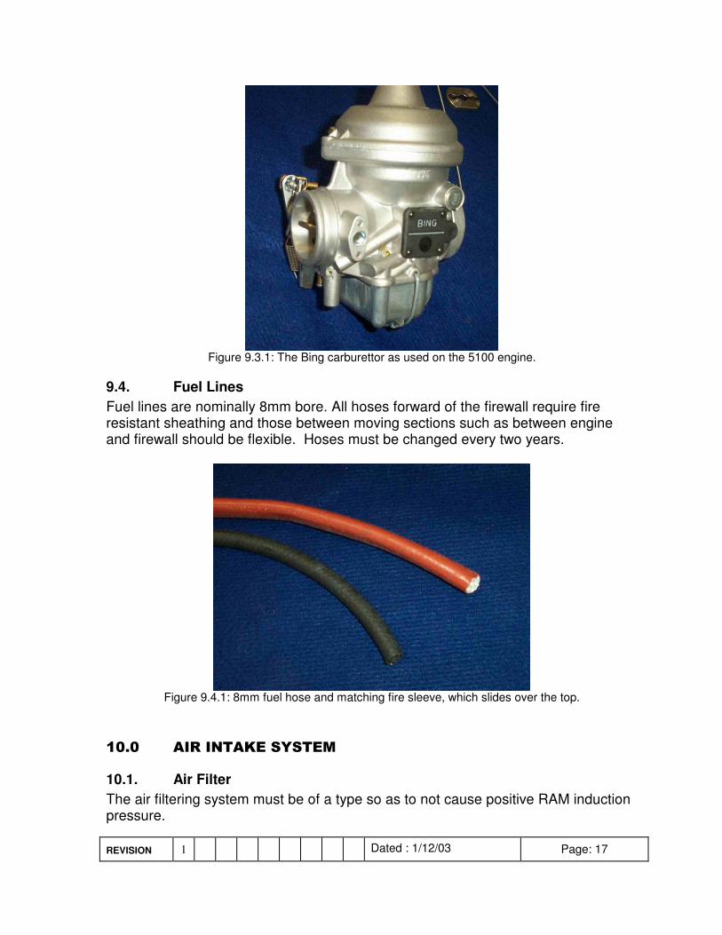
9.3. Carburettor A Bing constant depression type is used. This carburettor has a minimum delivery pressure of 5 kPa (0.75 Psi) and a maximum pressure of 20 kPa (3 psi). To confirm that the fuel system is capable of delivering this pressure a fuel flow test must be performed. A method for performing a fuel flow test is available from Jabiru if required. Because the engine is run in on a dynamometer some adjustment of the 7mm idle set screw may have to be made. A hot idle of around 600 - 700 RPM is desirable. Earth strap from carburettor to crankcase is recommended.
REVISION 1 Dated : 1/12/03 Page: 17
Figure 9.3.1: The Bing carburettor as used on the 5100 engine.
9.4. Fuel Lines Fuel lines are nominally 8mm bore. All hoses forward of the firewall require fire resistant sheathing and those between moving sections such as between engine and firewall should be flexible. Hoses must be changed every two years.
Figure 9.4.1: 8mm fuel hose and matching fire sleeve, which slides over the top.
�� � ���������������� �
10.1. Air Filter The air filtering system must be of a type so as to not cause positive RAM induction pressure.
REVISION 1 Dated : 1/12/03 Page: 18
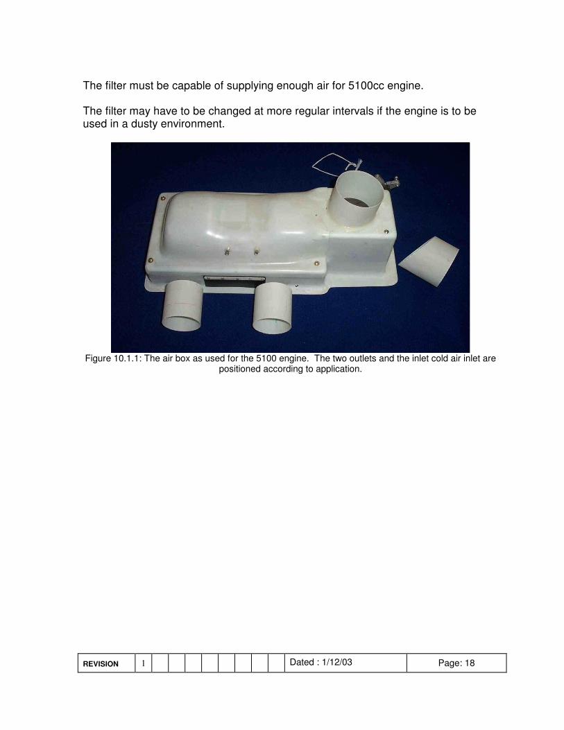
The filter must be capable of supplying enough air for 5100cc engine. The filter may have to be changed at more regular intervals if the engine is to be used in a dusty environment.
Figure 10.1.1: The air box as used for the 5100 engine. The two outlets and the inlet cold air inlet are
positioned according to application.
REVISION 1 Dated : 1/12/03 Page: 19
�� � �"������������ �
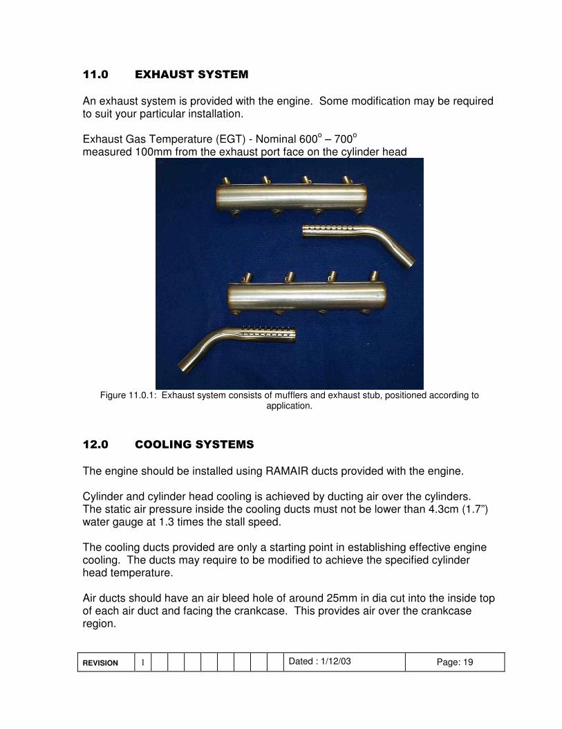
An exhaust system is provided with the engine. Some modification may be required to suit your particular installation. Exhaust Gas Temperature (EGT) - Nominal 600o – 700o measured 100mm from the exhaust port face on the cylinder head
Figure 11.0.1: Exhaust system consists of mufflers and exhaust stub, positioned according to
application. �� � ��������������
The engine should be installed using RAMAIR ducts provided with the engine. Cylinder and cylinder head cooling is achieved by ducting air over the cylinders. The static air pressure inside the cooling ducts must not be lower than 4.3cm (1.7”) water gauge at 1.3 times the stall speed. The cooling ducts provided are only a starting point in establishing effective engine cooling. The ducts may require to be modified to achieve the specified cylinder head temperature. Air ducts should have an air bleed hole of around 25mm in dia cut into the inside top of each air duct and facing the crankcase. This provides air over the crankcase region.
REVISION 1 Dated : 1/12/03 Page: 20
An oil cooler should be installed and sized to achieve oil temperatures within the engine limits. Jabiru’s recommended cooler is Jabiru P/N PN4A005N. Hoses should be nominally 10mm (3/8”) or 12.5mm (1/2”) bore and should be able to withstand pressure up to 150 PSI at 100 oC. Hoses must be changed every 2 years.
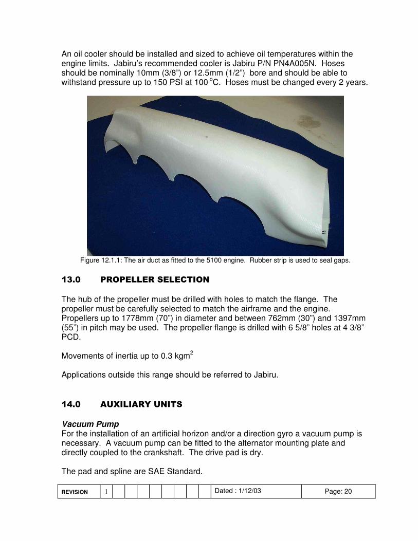
Figure 12.1.1: The air duct as fitted to the 5100 engine. Rubber strip is used to seal gaps.
�� � ������������������
The hub of the propeller must be drilled with holes to match the flange. The propeller must be carefully selected to match the airframe and the engine. Propellers up to 1778mm (70”) in diameter and between 762mm (30”) and 1397mm (55”) in pitch may be used. The propeller flange is drilled with 6 5/8” holes at 4 3/8” PCD. Movements of inertia up to 0.3 kgm2 Applications outside this range should be referred to Jabiru. �� � ��"������������
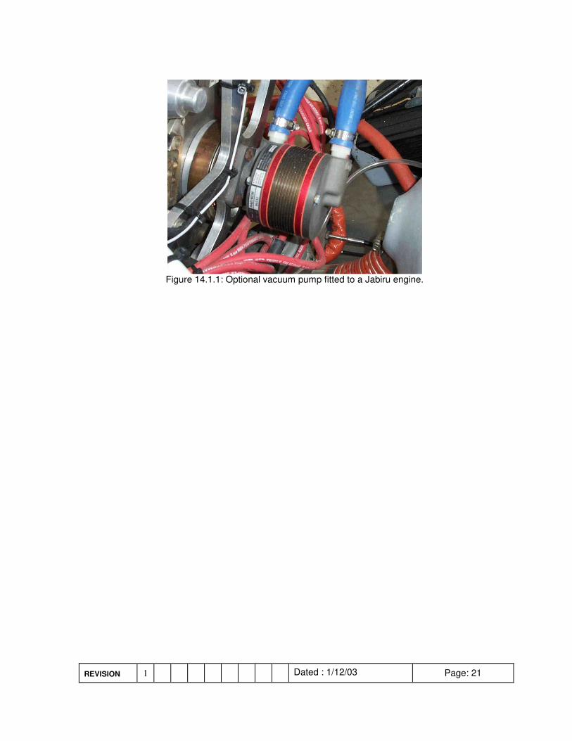
Vacuum Pump For the installation of an artificial horizon and/or a direction gyro a vacuum pump is necessary. A vacuum pump can be fitted to the alternator mounting plate and directly coupled to the crankshaft. The drive pad is dry. The pad and spline are SAE Standard.
REVISION 1 Dated : 1/12/03 Page: 21
Figure 14.1.1: Optional vacuum pump fitted to a Jabiru engine.
REVISION 1 Dated : 1/12/03 Page: 22
�##$%&'(���
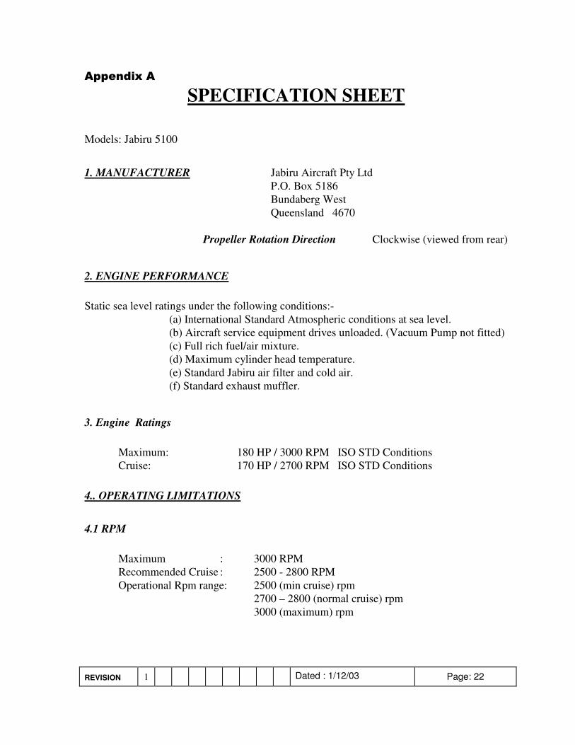
SPECIFICATION SHEET Models: Jabiru 5100 1. MANUFACTURER Jabiru Aircraft Pty Ltd P.O. Box 5186 Bundaberg West Queensland 4670 Propeller Rotation Direction Clockwise (viewed from rear)
2. ENGINE PERFORMANCE Static sea level ratings under the following conditions:- (a) International Standard Atmospheric conditions at sea level. (b) Aircraft service equipment drives unloaded. (Vacuum Pump not fitted) (c) Full rich fuel/air mixture. (d) Maximum cylinder head temperature. (e) Standard Jabiru air filter and cold air. (f) Standard exhaust muffler.
3. Engine Ratings Maximum: 180 HP / 3000 RPM ISO STD Conditions Cruise: 170 HP / 2700 RPM ISO STD Conditions 4.. OPERATING LIMITATIONS 4.1 RPM Maximum : 3000 RPM Recommended Cruise : 2500 - 2800 RPM Operational Rpm range: 2500 (min cruise) rpm 2700 – 2800 (normal cruise) rpm 3000 (maximum) rpm
REVISION 1 Dated : 1/12/03 Page: 23
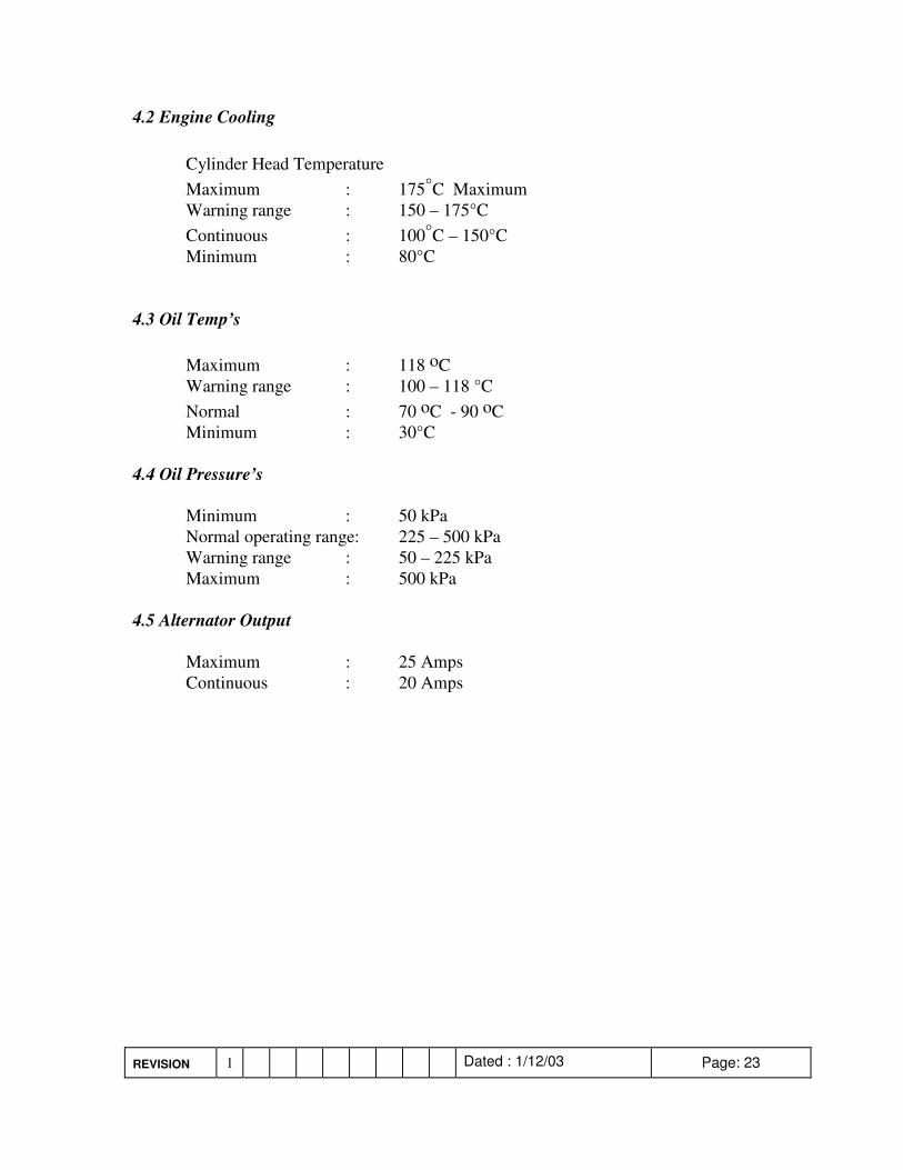
4.2 Engine Cooling Cylinder Head Temperature Maximum : 175°C Maximum Warning range : 150 – 175°C Continuous : 100°C – 150°C Minimum : 80°C 4.3 Oil Temp’s Maximum : 118 oC Warning range : 100 – 118 °C Normal : 70 oC - 90 oC Minimum : 30°C 4.4 Oil Pressure’s Minimum : 50 kPa Normal operating range: 225 – 500 kPa Warning range : 50 – 225 kPa Maximum : 500 kPa 4.5 Alternator Output Maximum : 25 Amps Continuous : 20 Amps