4915 EVC-H heat detector Manual new:4915 EVC-H heat ... EVC-H Heat Detector forms part of a brand...
10
NITTAN (UK) LTD. Hipley Street, Old Woking, Surrey, England, GU22 9LQ. UK Tel: +44 (0) 1483 769555 • Fax: +44 (0) 1483 756686 Web Site: www.nittan.co.uk • E-mail: [email protected] • Ref No: NISM/EVC-H/04 • Date: 17.08.09 • Issue: 4 • evolution • EVC-H • heat detector instruction manual EVC-H HEAT DETECTOR instruction manual Quality System Certificate No. 041 Assessed to BS EN ISO 9001:2000
-
Upload
truonghanh -
Category
Documents
-
view
220 -
download
0
Transcript of 4915 EVC-H heat detector Manual new:4915 EVC-H heat ... EVC-H Heat Detector forms part of a brand...

NITTAN (UK) LTD. Hipley Street, Old Woking, Surrey, England, GU22 9LQ. UKTel: +44 (0) 1483 769555 • Fax: +44 (0) 1483 756686 Web Site: www.nittan.co.uk • E-mail: [email protected]
• Ref No: NISM/EVC-H/04 • Date: 17.08.09 • Issue: 4
• evolution • EV C-H • heat detector instruction manual
EVC-HHEAT DETECTOR
instruction manual
Quality System Certificate No. 041Assessed to BS EN ISO 9001:2000

Technical Manual: EVC-H - 000014 (Changes are subject to DCRN)
evolution.....The EVC-H Heat Detector forms part of a brand new range of fire
detectors from Nittan (UK) Ltd called evolution.
The EVC-H is an elegantly designed, low profile detector which is
aesthetically pleasing, thus enabling it to blend unobtrusively into
modern working environments.
The EVC-H is compatible with other existing conventional fire
detection systems.
evolution.....
2
• Ref No: NISM/EVC-H/04 • Date: 17.08.09 • Issue: 4
• evolution • EV C-H • heat detector instruction manual

Technical Manual: EVC-H - 000014 (Changes are subject to DCRN)
Section 1 - INTRODUCTIONThe EVC-H is an attractively styled, fast response, low profile heat detector.
It has been designed to replace any previous Nittan heat detector.
EVC-H features:
• Low profile, stylish appearance
• Different response grades available
• Non-polarised terminals
• Unauthorised head removal signal facility
• Low monitoring current
• Patented OMNIVIEW™ 360º LED alarm indicator
• Remote indicator output
• Compatible with UB-4, UB-4SD and STB-4SE bases
Section 2 - OPERATIONThe EVC-H range of heat detectors are non mechanicaland use a thermistor of low thermal mass as the sensingelement giving a fast response. Although these detectorsoperate on a fixed temperature threshold only, their fastresponse makes them generally suitable for use whererate-of-rise detectors would be used.
3
• Ref No: NISM/EVC-H/04 • Date: 17.08.09 • Issue: 4
• evolution • EV C-H • heat detector instruction manual
Rem. Ind. (5)
OPERATION INDICATOR
VOLTAGE STABILISER
+ve(3)
-ve(1)-ve(6)
RECTIFIER AND
FILTER
SWITCHING UNIT
COMPARATOR UNIT
INTERNAL REFERENCE
SENSING THERMISTOR
Fig. 1. Block Diagram of EVC-H Detector Circuit
Fig. 1
CONTENTS:-
Section 1Introduction Page 3
Section 2Operation Page 3
Section 3Detector Models Page 4
Section 4Base Models Page 4
Section 5Installation Page 5
Section 6Connections Page 5
Section 7Maintenance & Page 6-7Cleaning
Section 8Specification Page 8
Section 9EMC Page 9
Section 10Dimensions Page 9
Section 11Disposal Page 10
Section 12ROHS Compliance Page 10Statement

Technical Manual: EVC-H - 000014 (Changes are subject to DCRN)4
Section 3 - DETECTOR MODELSThe EVC-H range of heat detectors are currently available
in two versions. Others can be made available upon demand.
i) EVC-H-A2S
ii) EVC-H-CS
These versions have three terminals for connection onto
the two wire zone circuit. The remaining terminal (5)
provides a switched current sink function which operates
when the detector goes into alarm condition, suitable for
the operation of auxiliary function such as a remote indicator.
Section 4 - BASE MODELSA variety of bases are available for use with the
EVC-H detectors. It is important to use the correct base
for each application. The available Base models are:
i) STB-4 / UB-4 base: for standard use with EVC-H series
heat detector.
ii) UB-4SD base: This is similar to the standard
UB-4 base, but also includes a schottky diode for head
removal fault monitoring. The schottky diode is used in
some fire systems to ensure power is maintained, in
the event of an unauthorised detector head removal,
to other detectors further on the zone.
iii) STB-4SE base: Similar to UB-4 base, except deeper.
• Ref No: NISM/EVC-H/04 • Date: 17.08.09 • Issue: 4
• evolution • EV C-H • heat detector instruction manual

Technical Manual: EVC-H - 000014 (Changes are subject to DCRN)
Section 5 - INSTALLATIONIn normal use, the EVC-H detector will be installed at
ceiling level. Pass field wiring through cable hole in
centre of base from rear of base. Offer up and affix
base to the ceiling or conduit fitting with screws via the
base mounting holes. Connect field wiring to base
terminals as detailed in below section 'Connections',
making sure that wiring will not obstruct fitting of detector
head. Fit detector head by inserting into base and
turning clockwise until notch in detector rim aligns with the
sensoris undertaken. At commissioning, the dust
cover should be removed and discarded.
NOTE: THE PLASTIC DUST COVER MUST BE REMOVED FROM THE
SENSOR IN ORDER FOR THE SENSOR TO FUNCTION CORRECTLY.
Section 6 - CONNECTIONSConnections are made to the detector base. The connections
used depend on the type of base and the functions required.
See Section 4 'Base Models', to identify the required type
of base and functions supported.
See below Figures 2, 3 & 4 for wiring to the detector's base:-
5
• Ref No: NISM/EVC-H/04 • Date: 17.08.09 • Issue: 4
• evolution • EV C-H • heat detector instruction manual
+
3
E.O.L1
6
_
UB-4 and STB-4-SE bases
FIG. 2
If +ve supply derived from zone, then RIL must be LED type
+3
1 5
6
_
UB-4 base
FIG. 3
+
R.I.L
_
Max. current through (5)= : 20 mA (total)
E.O.L
+
3
1
56
_
Max. current through (5)= : 20 mA (total)
E.O.L
UB-4-SD base
FIG. 4

Technical Manual: EVC-H - 000014 (Changes are subject to DCRN)6
Section 7 - MAINTENANCE AND CLEANING
Maintenance:
The EVC-H detector is a high quality product engineered
for reliability. In order to obtain optimum performance,
periodic maintenance is required. If proper preventative
maintenance is not carried out, there is a likelihood of
malfunction, including false alarms.
Servicing:
Servicing of the system should be carried out in accordance
with the requirements of BS 5839 Part 1, Fire
Detection and Alarm Systems for Buildings: Code of
Practice for System Design, Installation and Servicing.
The maintenance procedures described below, should
be conducted with the following frequency:
One month after installation: Routine Inspection and every 3 months thereafter.
Every 6 months: Operational Test.
Every 12 months: Functional Test and Cleaning.
All above frequencies of maintenance are dependent on
ambient conditions.
Routine Inspection:
i) Ensure that the detector head is secure and undamaged.
ii) Check that the heat entry apertures are in no way obstructed.
iii)Ensure that the surface of the detector’s outer cover
is clean. If there are deposits due to the presence of oil
vapour, dust etc, then the detector should be cleaned in
accordance with the cleaning instructions detailed later in
this manual. It may be advisable to ensure that such
cleaning is conducted regularly in future.
• Ref No: NISM/EVC-H/04 • Date: 17.08.09 • Issue: 4
• evolution • EV C-H • heat detector instruction manual

Technical Manual: EVC-H - 000014 (Changes are subject to DCRN)7
• Ref No: NISM/EVC-H/04 • Date: 17.08.09 • Issue: 4
• evolution • EV C-H • heat detector instruction manual
iv) Ensure that no equipment which may generate
excessive heat has been installed in the vicinity of the
detector since the last routine inspection. If such
equipment has been installed, then you should notify
the Safety Officer or other competent authority that its
presence may cause false alarms.
Operational Test
The purpose of the Operational Test is to confirm the
detector s correct operation in response to a heat condition.
i) Take any necessary precautions at the control panel to
limit the sounding of the alarm sounders/bells and any fire
service summoning device.
ii) Test the detector with heat from a warm air gun
designed for heat detector testing (e.g. 'No Climb - Solo'
heat sensor tester). Check that the detector gives an
alarm condition within 10-20 seconds depending upon the
detector grade and the applied air temperature. Check
that the LED indicator on the detector illuminates.
N.B. Hot air blowers sold for paint stripping, soldering
pipes etc, generate sufficient heat to damage the detector
and should not be used for testing heat detectors.
iii)After the detector has given the alarm condition,
reset the detector from the control. It may be necessary
to allow some short time to elapse before resetting the
detector, to allow any residual heat from the test to disperse.
iv) Before proceeding to the next detector, ensure that
the detector just tested does not re-operate due to the
presence of residual heat.
Functional Test:
The Functional Test checks the detectors operation.
These detectors may be returned to our factory for
Functional Testing.

Technical Manual: EVC-H - 000014 (Changes are subject to DCRN)8
• Ref No: NISM/EVC-H/04 • Date: 17.08.09 • Issue: 4
• evolution • EV C-H • heat detector instruction manual
Cleaning:
Note: The sensor head should NOT be disassembled.
i) Carefuly remove the heat detector from its base.
ii) Use a soft, lint-free cloth, moistened with alcohol for
sticky deposits, to clean the plastic cover.
iii)Using a soft bristle brush (e.g. an artists paintbrush)
carefully brush between the vanes and thermistor in a
linear motion away from the apertures on the plastic case.
iv) Ensure that no debris is left on or around the thermistor
once cleaning is complete.
v) If the unit needs further cleaning or is damaged or
corroded, please return the complete detector to Nittan
(UK) Ltd. for service.
Section 8 - SPECIFICATIONSModel References: EVC-H-A2S, EVC-H-CS
Computer References: EVC-H-A2S - F04N82505EVC-H-CS - F04N82507
Sensing Element & Principle: Thermistor of lowthermal mass.
Supply Voltage: 24V dc nominal (range 11to 32V)
Voltage Ripple: 20% maximum
Alarm Voltage: 6V d.c. in series with 375Rbetween +(terminal 3) and -(terminals 1,6) at 25ºC
Monitoring Current: 30 µA maximum at 24Vd.c.
Alarm Current: 50 mA maximum at 24Vd.c
Charging Time: 30 seconds
Technical Manual: EVC-H - 000014 (Changes are subject to DCRN)9
• Ref No: NISM/EVC-H/04 • Date: 17.08.09 • Issue: 4
• evolution • EV C-H • heat detector instruction manual
Typical Application Temperature: EVC-H-A2S 25 ºCEVC-H-CS 55 ºC
Maximum Application Temperature: EVC-H-A2S 50 ºCEVC-H-CS 80 ºC
Min. and Max. EVC-H-A2S 54 ºC / 70 ºCStatic Response Temperature: EVC-H-CS 84 ºC / 100 ºC
Min. Ambient Temperature: -10 ºC
IP Rating: 40
Section 9 - EMCInstallation
The installation shall be in accordance with the regulations
either of the approval body for an approved system,
or otherwise, to the national code of practice/ regulations
for the installation of the fire alarm system, e.g. BS 5839 part 1.
Electromagnetic Compatibility (EMC)
On a site where there is an unusually high level of potential
electrical interference, e.g. where heavy currents are being
switched or where high levels of R.F. are prevalent, then care
must be taken in the type and routing of cables. Particular care
should be given to the separation of zone wiring from the
cable carrying the interference.
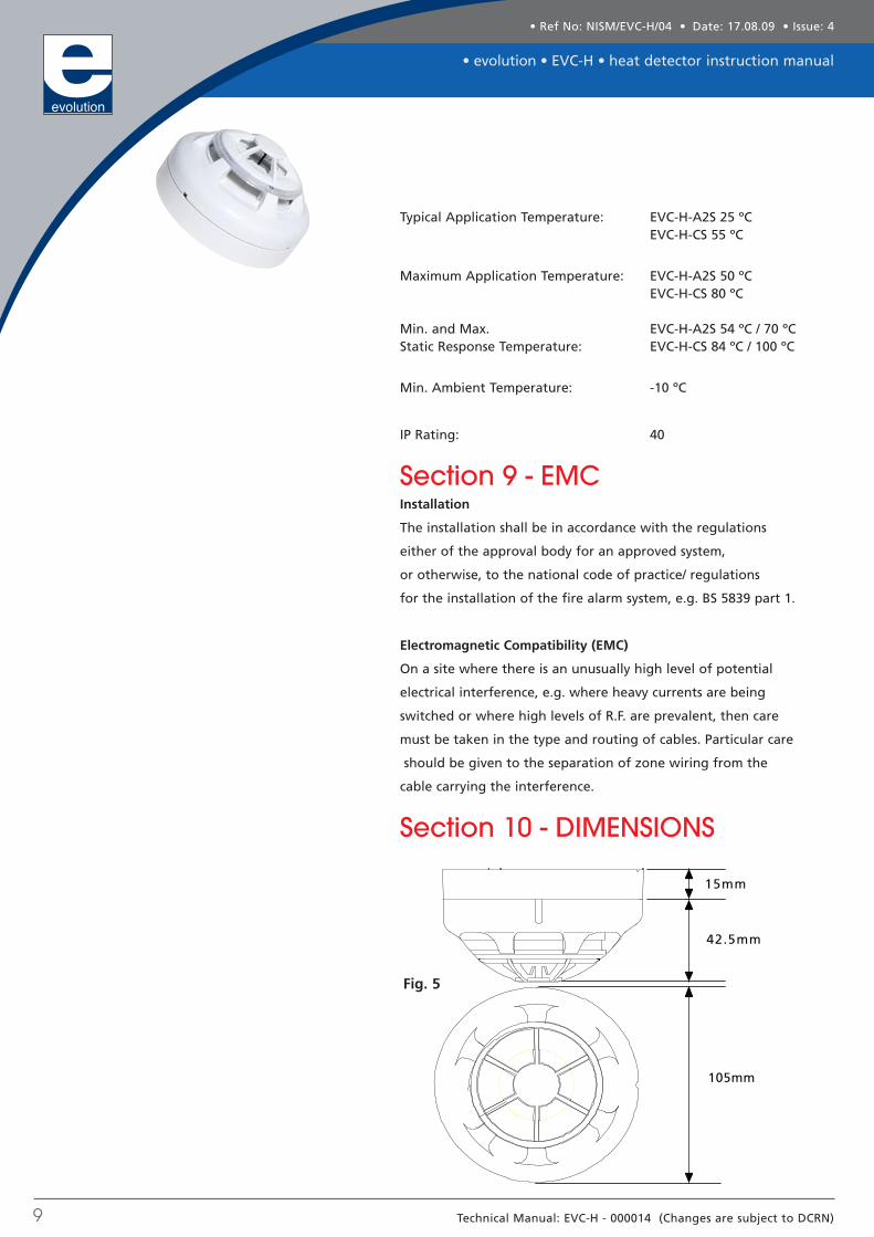
Section 10 - DIMENSIONS
15mm
42.5mm
105mm
Fig. 5

Technical Manual: EVC-H - 000014 (Changes are subject to DCRN)10
Section 11 - DISPOSALThis symbol on the EVC-H indicates that this product must not be
disposed of with household waste. Instead, it is your responsibility to
dispose of your waste equipment by handing it over to a designated
collection point for the recycling of waste electrical and electronic
equipment. The separate collection and recycling of your waste
equipment at the time of disposal will help to conserve natural
resources and ensure that it is recycled in a manner that protects
human health and the environment. For more information about
where you can drop off your waste equipment for recycling, please
contact your local city office or your household waste disposal service.
Section 12 - ROHS COMPLIANCE STATEMENT
(RoHS compliant and lead-free)
This product complies with the RoHS (Restriction of HazardousSubstances) directive.
This product complies with the RoHS (Restriction of HazardousSubstances) directive which restricts the use of six hazardousmaterials in the manufacture of electronic and electrical equipment.
This product complies with the European Union RoHS (Restriction ofHazardous Substances) directive 2002/95/EC which restricts the useof the following six hazardous materials in the manufacture ofelectronic and electrical equipment.
• Lead (Pb)• Hexavalant Chromium• Mercury (Hg)• Cadmium (Cd)• Polybrominated biphenyls (PBB’s)• Polybrominated diphenyl ethers (PBDE’s)
• Ref No: NISM/EVC-H/04 • Date: 17.08.09 • Issue: 4
• evolution • EV C-H • heat detector instruction manual