44449.2 SPM DX4RPRO AVC InstructionManual … 41&,53 3 13 • 53"/4 */4536$5*0 ."/6"-EN WARNING:...
24
Instruction Manual Bedienungsanleitung Manuel d’utilisation Manuale di istruzioni DX4R PRO 4-Channel 2.4GHz DSMR™ System
Transcript of 44449.2 SPM DX4RPRO AVC InstructionManual … 41&,53 3 13 • 53"/4 */4536$5*0 ."/6"-EN WARNING:...

Instruction Manual
Bedienungsanleitung
Manuel d’utilisation
Manuale di istruzioni
DX4R PRO4-Channel 2.4GHz DSMR™ System

2 Spektrum DX4r prO • tranSmitter inStructiOn manual
EN
WARNING: Read the ENTIRE instruction manual to become familiar with the features of the product before operating. Failure to operate the product correctly can result in damage to the product, personal property and cause serious injury.
This is a sophisticated hobby product. It must be operated with caution and common sense and requires some basic mechanical ability. Failure to operate this product in a safe and responsible manner could result in injury or damage to the product or other property. This product is not intended for use by children without direct adult supervision. Do not attempt disassembly, use with incompatible components or augment product in any way without the approval of Horizon Hobby, LLC. This manual contains instructions for safety, operation and maintenance. It is essential to read and follow all the instructions and warnings in the manual, prior to assembly, setup or use, in order to operate correctly and avoid damage or serious injury.
WARNING AGAINST COUNTERFEIT PRODUCTS Always purchase from a Horizon Hobby, LLC authorized dealer to ensure authentic high-quality Spektrum product. Horizon Hobby, LLC disclaims all support and warranty with regards, but not limited to, compatibility and performance of counterfeit products or products claiming compatibility with DSM or Spektrum.
Age Recommendation: Not for Children under 14 years. This is not a toy.
WARRANTy REGISTRATIONVisit community.spektrumrc.com today to register your product.
SAFETy PRECAUTIONS• Always ensure all batteries have been properly charged
prior to using the model.
• Always check all servos and their connections prior to each run.
• Never operate your model near spectators, parking areas or any other area that could result in injury to people or damage of property.
• Never operate your model during adverse weather conditions. Poor visibility can cause disorientation and loss of control of your model.
• Never point the transmitter antenna directly toward the model. The radiation pattern from the tip of the antenna is inherently low.
• If at any time during the operation of your model you observe any erratic or abnormal operation, immediately stop operation of your model until the cause of the problem has been ascertained and corrected.
NOTICEAll instructions, warranties and other collateral documents are subject to change at the sole discretion of Horizon Hobby, LLC. For up-to-date product literature, visit horizonhobby.com and click on the support tab for this Product.
MEANING OF SPECIAl lANGUAGEThe following terms are used throughout the product literature to indicate various levels of potential harm when operating this product:
NOTICE: Procedures, which if not properly followed, create a possibility of physical property damage AND little or no possibility of injury.
CAUTION: Procedures, which if not properly followed, create the probability of physical property damage AND a possibility of serious injury.
WARNING: Procedures, which if not properly followed, create the probability of property damage, collateral damage and serious injury OR create a high probability of superficial injury.
NOTICE: This product is only intended for use with unmanned, hobby-grade, remote-controlled vehicles and aircraft. Horizon Hobby disclaims all liability outside of the intended purpose and will not provide warranty service related thereto.

3Spektrum DX4r prO • tranSmitter inStructiOn manual
EN
TABlE OF CONTENTS
A. Switch A
B. Switch B
C. Switch C
D. Switch D
E. Switch E
F. Switch F
G. Roller Selector
H. Rubber Grip
I. Memory Card Port (under rubber grip)
J. Power Switch
K. Battery Cover
L. Throttle Trigger
M. Steering Wheel
N. Antenna
O. LCD Screen
P. RF LED
IDENTIFyING CONTROlS AND SWITChES
Slide the power switch (J) to power ON the transmitter. A Spektrum logo screen will appear, then the Main Screen will show on the LCD screen (O).
K
O
A
B
C
N
L
M
J
I
H
F
E
D
G
P
Warranty Registration ...................................................2Identifying Controls and Switches ..................................3Installing Batteries ........................................................4ModelMatch ................................................................4Charging .....................................................................5The Rubber Grip ..........................................................5Updating the Firmware .................................................5Warning Screens .........................................................6 Low Battery Alarm Inactivity AlarmReceiver Compatibility ..................................................6Main Screen ................................................................7Programming Guide .....................................................7 Individual Direction AdjustmentsList ............................................................................7Model Select ...............................................................8Travel ..........................................................................8Steering Rate ...............................................................9Exponential .................................................................9Binding......................................................................11
Frame Rate ................................................................11Servo Speed ..............................................................12Mixing .......................................................................12Active Vehicle Control (AVC) ........................................14ABS (Automatic Breaking System or pulse brakes) .......14Idle Up ......................................................................15Traction .....................................................................15Trim Step ...................................................................15Reset ........................................................................16Monitor .....................................................................16System .....................................................................17 Changing from Dropdown to Standard Wheel ..............19Changing to Left-Handed Configuration .......................20Troubleshooting Guide ................................................201-Year Limited Warranty .............................................21FCC Information .........................................................22IC Information ............................................................23Compliance Information for the European Union ...........23

4 Spektrum DX4r prO • tranSmitter inStructiOn manual
EN
Q. Steering Tension Adjustment Screw
R. Throttle Tension Adjustment Screw
S. Trigger Sizing
Q R S
STEERING TENSION ADjUSTMENT The steering tension is adjustable using the screw below the steering wheel. Turn the screw clockwise to increase the steering tension.
ThROTTlE TENSION ADjUSTMENT The trigger tension is adjustable using the screw in front of the throttle trigger. Turn the screw clockwise to increase the trigger tension.
TRIGGER SIzINGYou can adjust the trigger to fit your driving style. To adjust the trigger:
1. Loosen the screw on the back of the trigger.
2. Adjust the trigger spacing as necessary.
3. Tighten the screw on the back of the trigger.
INSTAllING BATTERIES
CAUTION: NEVER remove the transmitter batteries while the model is powered on. Loss of model control, damage or injury may occur.
MODElMATCh
The Spektrum DX4R PRO transmitter features ModelMatch™ technology, preventing you from operating a vehicle when the wrong model memory is active in the transmitter. If you select the wrong model memory, the receiver will not respond to the transmitter.

5Spektrum DX4r prO • tranSmitter inStructiOn manual
EN
DX4R PRO transmitters with part numbers that end in E do not have charge jacks.
All Spektrum charge jacks are center pin negative. Before using a charger, use a voltmeter to make sure the connector is center pin negative. When charging, use a charger designed for four cells (4.8-volt battery pack).
ChARGING WARNINGS
WARNING: Failure to exercise caution while using this product and comply with the following warnings could result in product malfunction, electrical issues, excessive heat, FIRE, and ultimately injury and property damage.
• Read all safety precautions and literature prior to use of this product.
• Never leave the battery and charger unattended during use.
ChARGING (NOT AvAIlABlE ON All TRANSMITTERS)
Charger Pigtail for Transmitter
Spektrum Transmitter Charge Jack Polarity
BLACK TO POSITIVE
BLACK W/WHITE STRIPE TO NEGATIVE
- +
• Never allow children under 14 years of age to charge battery packs.
• Never attempt to charge dead or damaged batteries.
• Never charge a battery if the cable has been pinched or shorted.
• Never allow batteries or charger to come into contact with moisture at any time.
• Never charge batteries in extremely hot or cold places (recommended between 50–80°F (10–26°C)) or place in direct sunlight.
• Always use only Ni-MH rechargeable batteries. This charger cannot charge batteries such as “heavy duty”, “alkaline”, “mercury” or “lithium” battery.
• Always connect to the charger correctly.
• Always disconnect the battery and charger after charging and let them cool between charges.
• Always inspect the battery before charging.
• Always terminate all processes and contact Horizon Hobby if the product malfunctions.
• Always make sure you know the specifications of the battery to be charged or discharged to ensure it meets the requirements of this charger.
• Always constantly monitor the temperature of the battery pack while charging.
• Always end the charging process if the charger or battery becomes hot to the touch or starts to change form during the charge process.
• Always charge in a well-ventilated area.
ThE RUBBER GRIP
This transmitter includes 2 sizes of grips. The small-size grip is installed at the factory.
To change the rubber grip
1. Lift the edge of the grip and pull the grip away from the handle.
2. Align the tabs on the new grip with the slots in the handle.
3. Press the grip against the handle.
1. Remove the grip from the back of the transmitter handle.
2. Download the latest firmware from www.SpektrumRC.com to an SD card. The transmitter serial number can be found by going to the About screen.
3. Install the SD card in the card reader slot on the DX4R PRO transmitter.
4. Power on the transmitter. A Spektrum logo and an installation bar will appear. Installation is complete when the Main screen appears.
5. Remove the SD card from the card slot on the transmitter.
6. Re-install the rubber grip on the transmitter handle.
UPDATING ThE FIRMWARE
The DX4R PRO features an SD card reader, enabling you to update the transmitter when firmware updates are available. Register your transmitter at www.SpektrumRC.com to receive the latest information regarding firmware updates. To install firmware updates on your DX4R PRO transmitter:

6 Spektrum DX4r prO • tranSmitter inStructiOn manual
EN
RECEIvER COMPATIBIlITy
The DX4R PRO transmitter is compatible with Spektrum™ DSMR™ and DSM2® receivers. The included SR410 DSMR receiver is only compatible with DSMR transmitters.
AvC – ACTIvE vEhIClE CONTROlAVC™ technology is the newest Spektrum™ RC innovation from Horizon Hobby. This Spektrum stabilization system adds a whole new level of control to your RC driving experience. AVC technol-ogy utilizes sensors to adjust steering and throttle output, provid-ing you with a more stable and controlled driving experience.
NOTICE: You must use digital servos with the SRS4210 receiver. Using analog servos will reduce the performance of the system and may cause analog servos to overheat.
Install the receiver in your vehicle using double-sided foam servo tape. Foam servo tape holds the receiver in place and protects the receiver from vibration. Position the antenna vertically and away from the vehicle in an antenna tube. The SR410 has a coax style antenna. The last 31mm of the antenna is the portion that receives the signal from the transmitter.
NOTICE: Do not cut or bend the antenna or it could become damaged.
Aux 1 PortAux 2 Port
lED
Bind PlugBind/Battery Port
Steering PortThrottle Port
Antenna
lOW BATTERy AlARMAn alarm will sound and the voltage will flash on the main screen when the transmitter’s battery power falls below a set limit. This alarm reminds you to stop using the vehicle immediately; power off the transmitter and replace the batteries. Set the low battery limit using the System Screen.
INACTIvITy AlARMThe alarm reminds you to power off the transmitter and save battery power. If the transmitter is powered on for more than 10 minutes and no control movement is detected, the inactivity alarm will sound. Moving any control stops the alarm.
WARNING SCREENS
Steering Servo
EC3EC3
ElECTRIC vEhIClE INSTAllATION NITRO vEhIClE INSTAllATION
Electronic Speed
Control
To Motor
Receiver
ReceiverBattery
Steering Servo
Throttle Servo
Battery
SR2000 RECEIvERBuilt-in Antenna Tube Mount
Antenna
Antenna Tube
Aux Port
Throttle Port
Steering Port
Bind/Battery Port
lED

7Spektrum DX4r prO • tranSmitter inStructiOn manual
EN
USING ThE ROllING SElECTOR
Press the Selector to enter a highlighted function.
Roll the Selector to highlight a function or change settings and values when selected.
Press and hold the Selector for more than 3 seconds in any screen to return the display to the List Screen or the Main Screen.
To program, always start with a press on the Selector, then roll, then press, then roll, and so on.
INDIvIDUAl DIRECTION ADjUSTMENTSIn some instances, you may find it necessary to independently adjust the control directions; for example, if you want more travel for left steering than right steering, perform the following steps:
1. Scroll to the value you wish to change and press the Rolling Selector.
2. When both directions are selected, move the control (steering or throttle) toward the control direction you wish to change. The selection box moves to the desired direction. You do not need to hold the control in the desired direction.
3. To change the opposite direction, simply move the control in that direction.
4. Press the Rolling Selector to save the selection.
MAIN SCREEN
The Main Screen displays information about the active model, including the Timer (when activated). To return to the Main Screen at any time, press and hold the Rolling Selector for at least 3 seconds.
A. User Name
B. Name assigned to the Model memory
C. Timers (when activated)
D. Transmitter Battery Voltage
E. Steering Percent
F. Position of Steering (St) trim
G. Position of Throttle (Th) trim
H. Position of Aux 1 trim
I. Position of Aux 2 trim
J. Brake Percent
PROGRAMMING GUIDE
TurnPress Press
To Enter, Choose or Exit a selection.
To move between options or change values in an option.
Hold for 3 seconds and release to return to the Main or Telemetry screen.
ROll hOlDPRESS
lIST
The List Screen shows other screens to set programming in the transmitter. A dark box with a clear symbol or text represents the highlighted selection. The Active Screen name is displayed at the top of the screen. Choosing the arrow will open the next higher screen, such as Main Screen or this List Screen. A small bar shows the relative position of a highlighted screen name in the List.
A
E
F
G
H
I
J
C
B
D

8 Spektrum DX4r prO • tranSmitter inStructiOn manual
EN
SElECTUse the Model Select menu to change the model memory, to assign a model name or to copy a model. The DX4R PRO has 50 model memories available.
CAUTION: NEVER change the model in Model Select while operating a model. Changing the model memory interrupts the transmitter signal to the receiver and may cause loss of vehicle control, damage or personal injury.
NAMEEnables you to name the selected model memory using up to ten characters.
1. Use the roller to select a Model Name in the List.
2. Select the character you want to change. A list of characters appear.
3. Select the character you want to use.
4. When you are finished naming the model memory, select the arrow to save the name and return to the list.
COPyThe Copy function shares active model memory settings with a selected model memory space. This is useful for saving setups for one model to adjust program-ming for track conditions or model setups.
Choosing No returns to the List Screen. Choosing Yes saves the active model settings to the selected model memory.
A. Active or source model memory number
B. Destination model memory number
IMPORTANT: When using the Copy function, model information will be permanently overwritten by the active model settings.
A
B
MODEl SElECT
Channel Top Bottom
Steering L (left) R (right)
Throttle B (brake) F (forward)
Aux 1 H (high) L (low)
Aux 2 H (high) L (low)
TRAvEl
The Travel function supports precise endpoint adjustments in all channels. Travel values range from 0–150% (Default is 100%).
NOTICE: Always check the control directions at the extents of travel to be sure the linkages do not bind. Travel values that are too high will cause binding, which may result in damage to the vehicle.

9Spektrum DX4r prO • tranSmitter inStructiOn manual
EN
IMPORTANT: Both positive and negative Expo values are available. A positive Expo value results in the center being less sensitive (desirable most of the time), while a negative value increases the sensitivity around center (normally not used).
ExPONENTIAl
Steering rate (dual rate) allows you to make on-the-fly steering travel adjustments using any of the Pro-grammable grip trimmers (A, B, C, D or E). The Steering Rate screen also offers a Steering override function, which allows you to access a second steering rate (normally 100%) at the touch of a button or trimmer. This is especially helpful for oval racers that program minimal steering throw to desensitize steering during racing, but requires maximum steering angle to drive out of a crash or get turned
around on the track. The user name, model number and model name are also displayed in this screen.
• From the List screen, highlight the Steering Rate function. Press the roller to access.
• Use the roller to select the S/R function or the S/R Override function by placing the box around the desired function.
• Press the roller to access S/R or S/R Override, then use the roller to change to the desired Steering rate value.
• Press the roller to set the value.
You can assign the adjustable S/R to any of the trimmers (A, B, C, D and E). The default is trimmer D. This trimmer works in unison with the S/R Rate screen. You can adjust the value using the assigned trimmer from either the S/R Rate screen or the Main screen. If you don’t want an on-the-fly adjustable Steering rate, you can inhibit the S/R trimmer.
IMPORTANT: In order for the S/R Override to operate, you must assign it to a switch or trimmer. The default position for this function is inhibited.
A. Channel: Steering, Throttle or Aux (auxiliary)
B. Direction
C. Adjustable value (from -100% to +100% (0 is factory default or inhibit))
A B C
STEERING RATE
The Exponential (Expo) function affects the response rate of the steering, throttle and/or brake. A positive Steering Expo value, for example, decreases steering sensitivity around neutral to make it easier to drive at high speeds in a straight line while still allowing for maximum turning radius. While sensitivity with positive Expo is decreased around neutral, it increases the sensitivity near the end of travel.

10 Spektrum DX4r prO • tranSmitter inStructiOn manual
EN
SUBTRIMThe Sub-Trim function enables you to correct minor servo arm offsets by electronically adjusting the center point of the servo. Sub-trim is avail-able on all channels.
• From the List screen, highlight the Sub-Trim function.
• Press the roller to access the Sub-Trim function. The Sub-Trim screen appears.
• Use the roller to select the chan-nel you wish to reverse.
-ST Steering -TH Throttle -AX Auxiliary
• Press the roller to highlight that channel. The surrounding box will flash. Rotate the roller to adjust the value and direction of the sub-trim.
• Press the roller to set the value.
Up Timer
The Up Timer is triggered via a selectable button/switch. It counts up from 00:00 seconds, functioning as a stopwatch. It is useful for timing a fuel run to determine fuel mileage/pit stop strategy or, for electrics, to time the run time of a pack to determine gear ratio and setup information. To pause the Up timer, press the button/switch the timer is programmed to. To reset the UP timer to 00:00, press and hold the programmed button for more than three seconds.
Down Timer
Is programmable for up to 99 minutes and 99 seconds in one-second increments. The Down timer is started via a selectable button/switch. When the down timer expires, an alarm sounds and the timer begins to count up. To pause the Down timer, press the button/switch the timer is programmed to. To reset the Down timer to its preprogrammed value, press and hold the programmed button for more than three seconds.
If Down timer is selected, press the roller again to change the time. Rotate the roller to change the time.
• From the List screen rotate the roller to highlight the Timer function.
• Press the roller to enter the Timer function. The Timer screen will display as shown below.
• Rotate the roller to highlight the desired Timer you choose to program (Timer A or Timer B).
• Press the roller to enter the highlighted Timer function.
• Rotate the roller to select the desired type within Timer A or Timer B:
– Int- Internal – Dn Tmr- Down Timer – Up Tmr- Up Timer – Lap- Rolling Lap Timer
TIMERThe DX4R PRO offers four types of timers:
Int Internal
Dn Tmr Down Timer
Up Tmr Up Timer
Lap Rolling Lap Timer
Timer A or B can be assigned to one of the four types. Both timers will be shown on the Main screen.
Internal Timer (Default Timer A)
Automatically records the time the transmitter is turned on. To
reset the internal timer, rotate the roller to highlight Internal Reset and then press the roller.
Rolling lap Timer (Default Timer B)
The Rolling Lap Timer is programmable from 0:00.5 to 4:59.9 minutes in 1-second increments. Start the Rolling Lap Timer via a selectable programmable switch. When the timer expires, an alarm sounds and the Lap timer resets and begins to count down again. To pause the timer, press the button/switch the timer is programmed to. To reset the timer to its preprogrammed value, press and hold the programmed button for more than three seconds. Button F defaults to the timer.
REvERSEThe Reverse function, also known as servo reversing, establishes the channel direction relative to the channel input. Use the reverse menu if, for example, the wheels turn left when you turn the steering wheel to the right. Reverse is available on all channels and is normally the first function you should test and adjust during programming.

11Spektrum DX4r prO • tranSmitter inStructiOn manual
EN
Binding is the Process of teaching the receiver the specific transmitter’s code called GUID (Globally Unique Identifier) and storing failsafe values. When a receiver is bound to a trans-mitter/model memory, the receiver will only respond to that specific transmitter/model memory (see ModelMatch for more information).
FAIlSAFEThe throttle failsafe position is set during binding. In the unlikely event that the radio link is lost during use, the receiver will drive the the throttle servo to its pre-Programmed failsafe position (normally full brakes) and all other channels will have no servo output. If the receiver is turned on prior to turning on the transmitter, the receiver will enter the failsafe mode, driving the throttle servo to its preset failsafe position. When the transmitter is turned on, normal control is resumed.
IMPORTANT: Failsafe activates only in the event that signal is lost from the transmitter. Failsafe will NOT activate in the event that receiver battery power decreases below the recommended minimums or power to the receiver is lost.
The Bind Screen shows the active model and supports binding the active model memory to a receiver.
BIND ThE TRANSMITTER TO ThE RECEIvER1. Insert a bind plug in the receiver’s BIND port.
2. Power on the receiver and wait until the receiver LED begins flashing.
3. Power on the transmitter.
4. Select the Model Memory you wish to bind to.
5. Select Bind from the List menu.
6. Move the throttle channel to the desired failsafe position.
IMPORTANT: The throttle channel must stay in the failsafe position until binding is complete.
7. Scroll to Bind and press the Rolling Selector. The orange LED flashes on top of the transmitter.
8. When the bind process is complete, the transmitter and receiver LEDs stop flashing and turn solid orange.
NOTICE: Always remove the bind plug from the receiver when the bind Process is complete. Failure to do so will cause the receiver to enter bind mode the next time you power on the receiver.
9. Remove the bind plug from the receiver and keep it in a convenient place.
BINDING
For compatiblity with all types of ser-vos, three frame rates are available.
5.5ms Gives the fastest response rate and is only compatible with with the SR2000 DSMR receiver and DSM2 receivers. Digital servos must be used with this frame rate.
IMPORTANT: When 5.5ms frame rate is selected, only two channels (steering and throttle) are operational.
11ms Offers good response rates and is compatible with most digital and analog servos (this is the default
position). Works with DSMR, DSM and DSM2 surface receivers.
16.5ms This is the least responsive rate and is needed for older analog servos. Works with both DSM and DSM2 surface receivers.
22ms This frame rate works with both DSMR and Marine receivers.
IMPORTANT: You should always use the fastest response rate the servos can handle. This gives the lowest latency and fast-est response. If the frame rate is incompatible with the servo, the servo will move erratically or, in some cases, not at all. If this occurs, change the frame rate to the next highest value.
• In the List screen, use the roller to highlight the Frame Rate function.
• Press the roller to access.
• Rotate the roller to select and highlight Frame Rate, at the bottom of the screen.
• Press the roller to highlight the Frame Rate function. The box will flash. Rotate the roller to select the frame rate.
FRAME RATE
DSM Protocol
Frame Rate

12 Spektrum DX4r prO • tranSmitter inStructiOn manual
EN
MIxING
SERvO SPEED
The Servo Speed function allows you to change the speed of any of the four channels— steering, throttle and Aux. from 100% (default) to 1%. The maximum speed is 100% and is fixed by the specifications of the servo itself.
• In the List screen, use the roller to highlight the Servo Speed function. Press the roller to access the Servo Speed function. The Servo Speed screen appears.
• Use the roller to select the desired channel, then press the roller to access that channel. Rotate the roller to adjust the servo speed.
STEER MIxUse the Steer Mix for vehicles requiring either four-wheel steering (4WS) or dual steering servos (Dual ST).
Mix Options
1. Select Aux1 or Aux2 as the slave channel. Aux1 and Aux2 can only be assigned to one mix at a time. If Aux1 or Aux2 is assigned to another mix, it will not be avail-able as a slave channel option.
2. Adjust the mix Value. The value shown is the percentage of slave channel input compared to master channel input.
For example, 100% means the slave channel movement is equal to the master channel movement. If you adjust the value to 50%, the slave channel moves half as far as the master channel. A negative value means the mix moves in the opposite direction.
4WS (4-Wheel Steering)
Trim: Act or Inh (Default). When Trim is Active, adjustments to the steering trim affect both front and rear steering channels.
Switch: Assign the 4-Wheel Steering Options to a switch to select steering options. Each time you move the switch, the 4-Wheel Steering options appear on the Main Screen.
Dual ST (Dual Steering)
Trim: Act (Default) or Inh. We recommend activating the Trim, as it adjusts the trim for both the left and right steering servos. If you need to make small adjustments to the individual servos, you can do so in the Sub-Trim menu.
ThROTTlE MIxDual Th Mix
Use the Dual TH Mix on vehicles that require two throttle channels.
1. Select Aux1 or Aux2 as the Slave channel. If Aux1 or Aux2 is assigned to another mix, it will not be available as a Slave channel option.
2. Adjust the Dual TH Mix Values to establish the throttle proportion between the throttle channels.
The DX4R PRO features preset steering and throttle mixes and four programmable mixes. If AVC™ technology is active, only two channels, Steering and Throttle, are operational. The Aux chan-nels can be used to power a personal transponder or lights.
If AVC technology is disabled (see Disabling the Stability Assist Function to disable AVC), the Aux channels will operate as servo channels. Aux channels are not available for use in mixes when AVC is active.

13Spektrum DX4r prO • tranSmitter inStructiOn manual
EN
Brake Mix
Use the Brake Mix on large scale vehicles that require separate front and rear brake servos. The mix value creates brake bias between the front and rear brakes. Assigning the Brake Mix to a switch enables you to adjust the mix value from any screen.
1. Select Aux1 or Aux2 as the Slavechannel. If Aux1 or Aux2 is assigned to another mix, it will not be available as a Slave channel option.
2. Adjust the Brake Mix Value to establish the brake bias between the front and rear brakes. Switch: You may assign the the Brake Mix to a switch. Assigning the Brake Mix to a switch enables you to adjust the brake bias from any screen.
You can assign custom names to the Programmable mixes, mak-ing it easier to remember what each mix does. Assign the names the same way you would for the Username or Model Name.
Mix Options
Trim: Inh or Act. When Trim is Active, trim adjustments to the Master channel also apply to the Slave channel.
Switch: You may assign the mix to a switch, enabling a B Value in the mix.
To adjust the B Value:
1. Assign a switch to the mix.
2. Press the switch forward or back. The A Value changes to B Value on the screen.
3. Select the B Value and move the scroll wheel to adjust the value.
4. Press the Rolling Selector to save the selection.
NOTICE: A negative value results in the secondary channel moving in a direction opposite the direction of the primary channel.
PROGRAMMABlE MIxThe Programmable mixes enable you to assign any channel as a Master or Slave, which is particularly helpful when you need to assign an Aux channel as a Master.
1. Scroll to Inh. Press the rolling selector once and select a Master channel.
2. Select a Slave channel.
3. Adjust the A Value percentage.
14 Spektrum DX4r prO • tranSmitter inStructiOn manual
EN
ABS (AUTOMATIC BRAkING SySTEM OR PUlSE BRAkES)
ABS helps prevent brake lock-ups and improves braking performance by pulsing the brakes.
You can adjust the following ABS parameters:
State: Inhibit or Active
Point: The throttle position that the pulse braking takes place (0 to 100, default is 60).
Stroke: The distance the throttle travels during the pulse braking (0 to 100, default is 50).
Lag: The time delay before the pulsing takes place (0.0 to 2.0 in .01 increments, default is 0.5).
Speed: The pulsing speed or frequency of the pulse braking (-1 to -30, default is -1).
The bar at the bottom of the screen displays the parameters and shows how ABS will function.
To activate ABS:
1. Select ABS from the List screen.
2. Select the ABS parameter you want to adjust.
3. Scroll up or down to adjust the parameter.
4. Press the scroll wheel to save the settings.
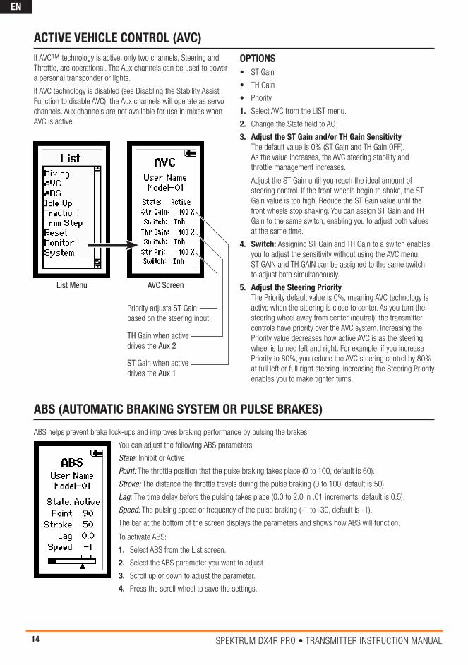
ACTIvE vEhIClE CONTROl (AvC)
OPTIONS• ST Gain
• TH Gain
• Priority
1. Select AVC from the LIST menu.
2. Change the State field to ACT .
3. Adjust the ST Gain and/or Th Gain Sensitivity The default value is 0% (ST Gain and TH Gain OFF). As the value increases, the AVC steering stability and throttle management increases.
Adjust the ST Gain until you reach the ideal amount of steering control. If the front wheels begin to shake, the ST Gain value is too high. Reduce the ST Gain value until the front wheels stop shaking. You can assign ST Gain and TH Gain to the same switch, enabling you to adjust both values at the same time.
4. Switch: Assigning ST Gain and TH Gain to a switch enables you to adjust the sensitivity without using the AVC menu. ST GAIN and TH GAIN can be assigned to the same switch to adjust both simultaneously.
5. Adjust the Steering Priority The Priority default value is 0%, meaning AVC technology is active when the steering is close to center. As you turn the steering wheel away from center (neutral), the transmitter controls have priority over the AVC system. Increasing the Priority value decreases how active AVC is as the steering wheel is turned left and right. For example, if you increase Priority to 80%, you reduce the AVC steering control by 80% at full left or full right steering. Increasing the Steering Priority enables you to make tighter turns.
AVC Screen
ST Gain when active drives the Aux 1
TH Gain when active drives the Aux 2
Priority adjusts ST Gain based on the steering input.
List Menu
If AVC™ technology is active, only two channels, Steering and Throttle, are operational. The Aux channels can be used to power a personal transponder or lights.
If AVC technology is disabled (see Disabling the Stability Assist Function to disable AVC), the Aux channels will operate as servo channels. Aux channels are not available for use in mixes when AVC is active.

15Spektrum DX4r prO • tranSmitter inStructiOn manual
EN
Idle up (also called high idle) is used to advance the throttle position on a gas car during startup to prevent the engine from dying before the engine is warmed up.
The following Parameters are available:
State: Inhibit or Active
Position: Adjusts the throttle position when idle up is engaged (0 to 100, default is 0)
Alarm: Activates an alarm when the Idle Up is active
The graphic bar at the bottom of the screen displays the parameters and shows how Idle Up will function.
The State must be Active to turn on the Idle Up function.
• In the List screen use the roller to highlight the Idle Up function.
• Press the roller to access the Idle UP function. The Idle Up screen appears.
• Use the roller to select the Parameter you wish to adjust. Press the roller to highlight that Parameter. The associated box will flash, then rotate the roller to adjust that function.
IMPORTANT: Idle Up must be assigned to a button in the System Screen under Switch select in order to operate the Idle Up function (See page 15, 16 for more details).
IDlE UP
TRACTION
Traction Control helps reduce wheel slippage and improve acceleration by gradually increasing the throttle. The following adjustable throttle parameters can be programmed:
State: Inhibit or Active
Point: The throttle position that traction control disengages. (5 to 100, default is 50)
Step: The distance the throttle travels during the reduced rate. (1 to 100, default is 1)
Delay: The time after pulling the trigger traction control engages. (0 to 25, default is 0)
The graphic bar at the bottom of the screen graphically displays the parameters and shows how traction control will function. State must be Active to turn on the Traction Control function.
1. In the List screen use the roller to highlight the Traction function.
2. Press the roller to access the Traction function. The Traction screen appears.
3. Use the roller to select the Traction parameter you wish to adjust.
4. Press the roller to highlight that parameter and the associated box will flash. Rotate the roller to adjust that function.
TRIM STEP
Trim Step affects the amount the servo travels with each click of the trim, but has no effect on the total trim travel. The trim steps range from 1 to 20 (Default is 4). To adjust the trim step:
1. Select Trim Step from the List menu.
2. Scroll to the desired channel and press the scroll wheel to activate the channel.
3. Rotate the scroll wheel to adjust the trim step.
4. Press the scroll wheel to save the selection.

16 Spektrum DX4r prO • tranSmitter inStructiOn manual
EN
MONITOR
The servo monitor displays the servo output positions graphically and digitally. This monitor can be useful in troubleshooting setups, displaying mixing functions and how they interrelate.
• In the List screen, use the roller to highlight the Monitor function.
• Press the roller to access the Monitor function. The real- time servo output positions will display.
RESET
The Model Reset function restores factory default settings for the active model memory.
• Choosing Yes affirms erasing saved settings for the active model memory and returns to factory defaults. A box shows around selected text.
• Choosing No returns to the List Screen.
IMPORTANT: Model information saved in a memory is erased when that model memory is copied over or reset to factory default settings.
USER NAMEIf you selected User Name, you will see a Confirm screen asking you to confirm the User Name Reset. Press the roller to select Yes or No.
CAlIBRATEThe calibrate function recalibrates the transmitter’s steering and brake potentiometers.
CAUTION: If calibration is not properly completed, the radio will not function correctly.
If after calibration the steering or throttle does not function properly (the travel is reduced or no servo travel), you will need to recalibrate the transmitter.
• In the List screen, use the roller to highlight the Reset function.
• Press the roller to access the Reset functions.
• Use the roller to select Calibrate.
• Press the roller to access the Confirm screen.
CAUTION: Once Yes is selected, you must complete all the calibration steps described in this section or the radio will not function properly.
• Use the roller to highlight Yes, then press the roller to reset.
IMPORTANT: The values will change to correlate with the actual potentiometers.
• Rotate the steering wheel full right, then full left, then move the throttle trigger to full throttle and full brake.
• After realigning steering and throttle/brakes, highlight SAVE. Press the roller to save the settings.

17Spektrum DX4r prO • tranSmitter inStructiOn manual
EN
SySTEM
The System function lets you adjust transmitter functions.
SWITChThe Switch menu enables you to as-sign any of the seven switches to one of the following functions. Switches that have a +/- next to the name can be assigned to different directions. For example, ST trim+ causes right steering trim to trim the steering to the right. ST trim- causes right steering trim to trim steering to the left. Aux1 and Aux2 can only be as-signed to one function at a time. For example, if Aux1 is assigned to 4WS Mix, then it it will not be available as an option on the switch screen.
DISPlAyContrastThe contrast function provides adjustment to the brightness ratio of the lightest to the darkest part of the screen. You can set the contrast to a value from 0 to 30 (0 is lightest and 30 is darkest).
lightYou can set the backlight to one of three modes:Timer, On or Off.
Timer: The backlight will turn off after a preset delay.
On: The backlight never turns off when the transmitter is on.
Off: The backlight is always off.
1. Use the Rolling Selector to access Light.
2. Press the roller and the surrounding box will flash.
3. Rotate the roller to the desired backlight mode and press the roller to select it.
Timeout
You can adjust the amount of time the backlight is on. The timeout only applies when Light is set to Timer.
Trims
Changing the Trim values will change the bars shown at the bottom of the Main screen. For example, if you select ST Trim for Pos. 1, the Steering Trim will appear in the first bar on the Main screen.
lang (language)
The DX4R PRO can display the screen text in one of four languages: English (default), German, French and Italian. Use the roller and select the Language function.
USERNAMEYou can program a user name with up to 10 characters. This name is displayed on the Main Screen. In the System screen, highlight the User Name and press the roller to access the function. Use the roller to select the position, then press the roller to access a character. Username affects all models.
Switch A, B, C, D, E
InhibitIdle UpAx1 LinAx1 2PAX1 3PAx1 MTAx1 Trm+Ax1 Trm-Ax1 Exp+Ax1 Exp-Ax2 LinAx2 2PAx2 3PAx2 MTAx2 Trm+Ax2 Trm-
Ax2 Exp+Ax2 Exp-Brake +Brake –Thr Trm +Thr Trm –Thr Exp +Thr Exp –S/R OvrdStr Trm +Str Trm –Str S/R +Str S/R –Str Exp +Str Exp –ROSS Bnd
ROSS Ax1ROSS Ax24WS MixBrake MixMOA MixTH BIASMix AMix BMix CMix DMix A RateMix B RateMix C RateMix D RateTimer
Switch F
InhibitAx1 2PAx2 2P
S/R OvrdROSS Ax1ROSS Ax2
ROSS BndTimer

18 Spektrum DX4r prO • tranSmitter inStructiOn manual
EN
AlERTYou can set an alarm to sound when the battery voltage gets to the limit set with the Alert. Battery voltage is displayed on the Main Screen.
Menu: None, Tone, Vibe, BothSets the alert type for scrolling through the menu items and selecting items.
ToneYou can adjust the buzzer to either Low or High.
IMPORTANT: Buzzer adjustment does not change the sound level for Inactivity or Low Battery warnings.
Tx Battery voltage Set an alarm to sound when the battery voltage gets to the limit set. The range is 4.0 to 7.0V.
CAUTION: Do not operate a model when the battery voltage is below 4.3V for AA batteries.
Tx Battery Alert Type: None, Tone, Vibe, Both
Timer: None, Tone, Vibe, BothSets the alert type for the down timer.
Telemetry Rx Battery Alert Type: None, Tone, Vibe, Both Sets the alert type for the telemetry receiver battery voltage.
Temp Alert Type: None, Tone, Vibe, Both Sets the alert type for the telemetry temperature. The telemetry alert settings are model specific.
All of the alert settings above affect all models.
ABOUTThis screen displays the transmitter serial number (which is required when downloading firmware updates) and the release level of the transmitter’s software. Refer to Memory Card instructions for updating transmitter firmware.
Serial
The Serial Number screen displays the transmitter serial number, as well as the RaceWare™ software version. You will need to provide the serial number when you register your transmitter on the Spektrum website.

19Spektrum DX4r prO • tranSmitter inStructiOn manual
EN
1.
Remove the batteries from the transmitter. This prevents the possibility of accidentally causing a short during the conversion.
2.
Using the 3/32-inch hex wrench, remove the three screws on the front of the steering housing as shown. Carefully remove the steering mechanism and unplug the steering connector. Also remove the steering shell but leave the backplate.
3.
Using the 3/32-inch hex wrench, remove the three screws on the front of the steering dropdown as shown. Select the appropriate Left/Right standard steering spacer and pass the steering wheel mechanism connector through the hole in the shell.
4.
Connect the steering wheel mechanism connector to the connector from the transmitter being sure the connection is tight. Note correct polarity. Fit the backplate in place and secure the standard steering wheel assembly using the three long cap screws.
ChANGING FROM DROPDOWN TO STANDARD WhEEl
The DX4R PRO comes with the dropdown wheel installed and can be switched to the standard wheel. All the parts necessary to convert to the standard wheel are included. The included 3/32-inch hex wrench and a small Phillips screwdriver will be needed.

20 Spektrum DX4r prO • tranSmitter inStructiOn manual
EN
1. Remove the batteries from the transmitter. This prevents the possibility of accidentally causing a short during the conversion.
2. Carefully remove the grip cover by prying with your fingers at the forward edge of the rubber grip.
3. Using the 3/32-inch hex wrench, remove the three screws on the front of the steering housing as shown.
4. Carefully remove the steering mechanism and unplug the steering connector. Also remove the backplate.
5. Using a small Phillips screwdriver, remove the four Phillips screws (two per side) that fasten the grip plates in place. Remove the grip plate that doesn’t have the buttons attached.
6. Carefully pull out the grip plate that contains buttons D, E and F. Using a Phillips screwdriver remove the PC board and backplate from the grip plate. Note the positions of the three buttons.
7. Transfer the three buttons (D, E and F) to the other “handed” grip plate (included in the box). The buttons fit in a specific direction so that they fit the external contour of the grip plate.
8. Carefully screw the PC board and backplate in place and test that all buttons are depressing properly.
9. Place both grip plates in place and fasten them using four Phillips screws (two per side).
10. Push the steering wheel connector through the transmitter case to the opposite side.
11. Select the opposite “handed” steering shell and pass the steering wheel mechanism connector through the hole in the shell.
12. Connect the steering wheel mechanism connector to the connector from the transmitter. Make sure the connection is tight. Note correct polarity.
13. Fit the other handed backplate in place and secure the steering wheel assembly in place using the three long cap head screws.
14. Fit the grip in place and reinstall the batteries. Note that the buttons D and E now work in reverse. You will need to change the direction of these switches in the System menu.
ChANGING TO lEFT-hANDED CONFIGURATION
The DX4R PRO comes set up for right-handed use, but you can easily switch it to a left-handed configuration. All the parts necessary to convert to left-handed, including the grip plates, the back cover and the front shell, are included. The included 3/32-inch hex wrench and a small Phillips screwdriver will be needed.
TROUBlEShOOTING GUIDE
PROBlEM POSSIBlE CAUSE SOlUTIONThe system will not connect
Transmitter and receiver too near each other Move transmitter 8 to 12 feet (2.4 to 3.6m) from receiver
Transmitter and receiver too near large metal objects (vehicles, etc.)
Move away from large metal objects (vehicles, etc.)
Selected model is not bound in transmitter Make sure correct model memory is selected and that transmitter is bound to the model
Transmitter accidentally put in bind mode so receiver is no longer bound
Rebind transmitter and receiver
The receiver goes into failsafe mode a short distance away from the transmitter
Check the receiver antenna to be sure it is not cut or damaged
Replace or contact Horizon product Support
Make sure receiver antenna is in an antenna tube and is above vehicle
Receiver quits responding during operation
Low battery voltage Completely recharge battery
Loose or damaged wires or connectors between battery and receiver
Do a check of the wires and connection between battery and receiver. Repair or replace wires and/or connectors
Receiver loses its bind
Transmitter accidentally put in bind mode, ending bind to receiver
Bind transmitter to receiver
Receiver taking longer than usual to link with transmitter
Transmitter and receiver are operating on Marine model
Marine receivers can take longer to link with transmitter

21Spektrum DX4r prO • tranSmitter inStructiOn manual
EN
What this Warranty CoversHorizon Hobby, LLC (Horizon) warrants to the original purchaser that the product purchased (the “product”) will be free from defects in materials and workmanship for a period of 1 year from the date of purchase.
What is Not CoveredThis warranty is not transferable and does not cover (i) cosmetic damage, (ii) damage due to acts of God, accident, misuse, abuse, negligence, commercial use, or due to improper use, installation, operation or maintenance, (iii) modification of or to any part of the product, (iv) attempted service by anyone other than a Horizon Hobby authorized service center, (v) product not purchased from an authorized Horizon dealer, or (vi) product not compliant with applicable technical regulations.
OTHER THAN THE EXPRESS WARRANTY ABOVE, HORIZON MAKES NO OTHER WARRANTY OR REPRESENTATION, AND HEREBY DISCLAIMS ANY AND ALL IMPLIED WARRANTIES, INCLUDING, WITHOUT LIMITATION, THE IMPLIED WARRANTIES OF NON-INFRINGEMENT, MERCHANTABILITY AND FITNESS FOR A PARTICULAR PURPOSE. THE PURCHASER ACKNOWLEDGES THAT THEY ALONE HAVE DETERMINED THAT THE PRODUCT WILL SUITABLY MEET THE REQUIREMENTS OF THE PURCHASER’S INTENDED USE.
Purchaser’s RemedyHorizon’s sole obligation and purchaser’s sole and exclusive remedy shall be that Horizon will, at its option, either (i) service, or (ii) replace, any product determined by Horizon to be defective. Horizon reserves the right to inspect any and all Product(s) in-volved in a warranty claim. Service or replacement decisions are at the sole discretion of Horizon. Proof of purchase is required for all warranty claims. SERVICE OR REPLACEMENT AS PROVIDED UNDER THIS WARRANTY IS THE PURCHASER’S SOLE AND EXCLUSIVE REMEDY.
limitation of liabilityHORIZON SHALL NOT BE LIABLE FOR SPECIAL, INDIRECT, INCIDENTAL OR CONSEQUENTIAL DAMAGES, LOSS OF PROFITS OR PRODUCTION OR COMMERCIAL LOSS IN ANY WAY, REGARD-LESS OF WHETHER SUCH CLAIM IS BASED IN CONTRACT, WAR-RANTY, TORT, NEGLIGENCE, STRICT LIABILITY OR ANY OTHER THEORY OF LIABILITY, EVEN IF HORIZON HAS BEEN ADVISED OF THE POSSIBILITY OF SUCH DAMAGES. Further, in no event shall the liability of Horizon exceed the individual price of the product on which liability is asserted. As Horizon has no control over use, setup, final assembly, modification or misuse, no liability shall be assumed nor accepted for any resulting damage or injury. By the act of use, setup or assembly, the user accepts all resulting li-ability. If you as the purchaser or user are not prepared to accept the liability associated with the use of the product, purchaser is advised to return the product immediately in new and unused condition to the place of purchase.
lawThese terms are governed by Illinois law (without regard to conflict of law principals). This warranty gives you specific legal rights, and you may also have other rights which vary from state to state. Horizon reserves the right to change or modify this warranty at any time without notice.
WARRANTy SERvICESQuestions, Assistance, and ServicesYour local hobby store and/or place of purchase cannot provide warranty support or service. Once assembly, setup or use of the product has been started, you must contact your local distributor or Horizon directly. This will enable Horizon to better answer your questions and service you in the event that you may need any assistance. For questions or assistance, please visit our website at www.horizonhobby.com, submit a Product Support Inquiry, or call the toll free telephone number referenced in the Warranty and Service Contact Information section to speak with a Product Support representative.
Inspection or ServicesIf this product needs to be inspected or serviced and is compliant in the country you live and use the product in, please use the Horizon Online Service Request submission process found on our website or call Horizon to obtain a Return Merchandise Authorization (RMA) number. Pack the product securely using a shipping carton. Please note that original boxes may be included, but are not designed to withstand the rigors of shipping without additional protection. Ship via a carrier that provides tracking and insurance for lost or damaged parcels, as Horizon is not responsible for merchandise until it arrives and is accepted at our facility. An Online Service Request is available at http://www.horizonhobby.com/content/_service-center_render-service-center. If you do not have internet access, please contact Horizon Product Support to obtain a RMA number along with instructions for submitting your product for service. When calling Horizon, you will be asked to provide your complete name, street address, email address and phone number where you can be reached during business hours. When sending product into Horizon, please include your RMA number, a list of the included items, and a brief summary of the problem. A copy of your original sales receipt must be included for warranty consider-ation. Be sure your name, address, and RMA number are clearly written on the outside of the shipping carton.
NOTICE: Do not ship li-Po batteries to horizon. If you have any issue with a li-Po battery, please contact the appropriate horizon Product Support office.
Warranty Requirements For Warranty consideration, you must include your origi-nal sales receipt verifying the Proof-of-purchase date. Provided warranty conditions have been met, your product will be serviced or replaced free of charge. Service or replacement decisions are at the sole discretion of Horizon.
1-yEAR lIMITED WARRANTy

22 Spektrum DX4r prO • tranSmitter inStructiOn manual
EN
Warranty and Service Contact Information
Country of Purchase horizon hobby
Phone Number / Email Address Address
United States of America
Horizon Service Center (Repairs and Repair Requests)
servicecenter.horizonhobby.com/RequestForm/
4105 Fieldstone Rd Champaign, Illinois, 61822 USA
Horizon Product Support (Product Technical Assistance)
www.quickbase.com/db/bghj7ey8c?a=GenNewRecord 888-959-2305
Sales [email protected] 888-959-2305
United Kingdom Service/Parts/Sales: Horizon Hobby Limited
[email protected] +44 (0) 1279 641 097
Units 1-4 Ployters Rd Staple Tye Harlow, Essex CM18 7NS, United Kingdom
Germany Horizon Technischer Service [email protected] +49 (0) 4121 2655 100
Christian-Junge-Straße 1 25337 Elmshorn, Germany
Sales: Horizon Hobby GmbH
France Service/Parts/Sales: Horizon Hobby SAS
[email protected] +33 (0) 1 60 18 34 90
11 Rue Georges Charpak 77127 Lieusaint, France
China Service/Parts/Sales: Horizon Hobby - China
[email protected] +86 (021) 5180 9868
Room 506, No. 97 Changshou Rd. Shanghai, China 200060
Non-Warranty ServiceShould your service not be covered by warranty, service will be completed and payment will be required with-out notification or estimate of the expense unless the expense exceeds 50% of the retail purchase cost. By sub-mitting the item for service you are agreeing to payment of the service without notification. Service estimates are available upon request. You must include this request with your item submitted for service. Non-warranty service estimates will be billed a mini-mum of 1/2 hour of labor. In addition you will be billed for return freight. Horizon accepts money orders and cashier’s checks, as well as Visa, MasterCard, American Express, and Discover cards. By submitting any item to Horizon for service, you are agreeing
to Horizon’s Terms and Conditions found on our website http://www.horizonhobby.com/content/_service-center_ render-service-center.
ATTENTION: horizon service is limited to Product compliant in the country of use and ownership. If re-ceived, a non-compliant product will not be serviced. Further, the sender will be responsible for arranging return shipment of the un-serviced product, through a carrier of the sender’s choice and at the sender’s expense. horizon will hold non-compliant product for a period of 60 days from notification, after which it will be discarded.
This device complies with part 15 of the FCC rules. Operation is subject to the following two conditions: (1) This device may not cause harmful interference, and (2) this device must accept any interference received, including interference that may cause undesired operation.
CAUTION: Changes or modifications not expressly approved by the party responsible for compliance could void the user’s authority to operate the equipment.
This product contains a radio transmitter with wireless technol-ogy which has been tested and found to be compliant with the applicable regulations governing a radio transmitter in the 2.400GHz to 2.4835GHz frequency range.
ANTENNA SEPARATION DISTANCEWhen operating your Spektrum transmitter, please be sure to maintain a separation distance of at least 5 cm between your body (excluding fingers, hands, wrists, ankles and feet) and the antenna to meet RF exposure safety requirements as determined by FCC regulations.
The illustrations below show the approximate 5 cm RF exposure area and typical hand placement when operating your Spektrum transmitter.
FCC INFORMATION

23Spektrum DX4r prO • tranSmitter inStructiOn manual
EN
AT BE BG CZ CY DE DK
EE ES FI FR GR HR HU
IE IT LT LU LV MT NL
PL PT RO SE SI SK UK
IS LI NO CH
DEClARATION OF CONFORMITy(in accordance with ISO/IEC 17050-1)
No. HH2013092101
Product(s): SPM DX4R 4 Channel DSMR Racing System Item Number(s): SPM4100, SPM4100E Equipment class: 2
The object of declaration described above is in conformity with the requirements of the specifications listed below, following the Provisions of the European R&TTE directive 1999/5/EC:
EN 300-328 V1.7.1: 2006 EN 301 489-1 V1.9.2: 2012 EN 301 489-17 V2.1.1: 2009
EN60950-1:2006+A11:2009+A1:2010+A12: 2011
Signed for and on behalf of: Horizon Hobby, LLC Champaign, IL USA September 21, 2013
COMPlIANCE INFORMATION FOR ThE EUROPEAN UNION
INSTRUCTIONS FOR DISPOSAl OF WEEE By USERS IN ThE EUROPEAN UNION
This product must not be disposed of with other waste. Instead, it is the user’s responsibility to dispose of their waste equipment by handing it over to a designated collections point for the recy-cling of waste electrical and electronic equipment. The separate collection and recycling of your waste equipment at the time of disposal will help to conserve natural resources and ensure that it is recycled in a manner that protects human health and the environment. For more information about where you can drop off your waste equipment for recycling, please contact your local city office, your household waste disposal service or where you purchased the product.
IC INFORMATION
This device complies with Industry Canada licence-exempt RSS standard(s). Operation is subject to the following two conditions: (1) this device may not cause interference, and (2) this device must accept any interference, including interference that may cause undesired operation of the device.
Mike Dunne Executive Vice President Product Divisions Horizon Hobby, LLC

44449.2 Printed: 10/2014
©2014 Horizon Hobby, LLC. DSM, DSM2, DSMR, ModelMatch, RaceWare, AVC, Active Vehicle Control and the Horizon Hobby logo are trademarks or registered trademarks of Horizon Hobby, LLC. The Spektrum trademark is used with permission of Bachmann Industries, Inc. The SD Logo is a trademark of SD-3C, LLC. Patents pending.