4536 4540.output
63
* GB784943 (A) Description: GB784943 (A) ? 1957-10-23 Improvements in and connected with arc welding Description of GB784943 (A) PATENT SPECIFICATION Inventors: RICHARD GILLOCK BRAITHWAITE and JOHIN LEONARD PRATT 784,943 Date of filing Complete Specification: Oct 19, 1955. Application Date: Nov 18, 1954. No 33391154. Complete Specification Published: Oct 23, 1957. Index at acceptance: -Class 83 ( 4), T( 2 D 2: 2 J: 6). International Classification:-B 23 k. COMPLETE SPECIF'ICATION Improvements in and Connected with Arc Welding We, BRAITHWAITE & COMPANY ENGINEERS LIMITED, of "The Moordings," Church Road, Great Bookham, Surrey, a British Company, do hereby declare the invention, for which we pray that a patent may be granted to us, and the method by which it is to be performed, to be particularly described in and by the following statement: - This invention is concerned with an improved method of and means for arc welding with continuous electrode wire.
Transcript of 4536 4540.output
* GB784943 (A)
Description: GB784943 (A) ? 1957-10-23
Improvements in and connected with arc welding
Description of GB784943 (A)
PATENT SPECIFICATION Inventors: RICHARD GILLOCK BRAITHWAITE and JOHIN LEONARD PRATT 784,943 Date of filing Complete Specification: Oct 19, 1955. Application Date: Nov 18, 1954. No 33391154. Complete Specification Published: Oct 23, 1957. Index at acceptance: -Class 83 ( 4), T( 2 D 2: 2 J: 6). International Classification:-B 23 k. COMPLETE SPECIF'ICATION Improvements in and Connected with Arc Welding We, BRAITHWAITE & COMPANY ENGINEERS LIMITED, of "The Moordings," Church Road, Great Bookham, Surrey, a British Company, do hereby declare the invention, for which we pray that a patent may be granted to us, and the method by which it is to be performed, to be particularly described in and by the following statement: - This invention is concerned with an improved method of and means for arc welding with continuous electrode wire. It is known in connection with such welding that if an electrode, charged with welding current at sufficiently high density, is fed into the arc at constant rate, the;arc length is automatically self-adjusted to that determined by the magnitude of the said welding current and the feed rate, that is, if the,arc tends to lengthen, the burn-off rate correspondingly reduces and vice versa, without any intervention Welding heads have accordingly been proposed for supplying current to a, single electrode wire Whilst feeding it through the head at constant rate. It is also known to be sometimes desirable to apply more than one arc simultaneously to the same weld, using separate electrode wires which Fare supplied with currents having differing characteristics, for which purpose it has been proposed thus to feed such wires by;a single drive.
According to the present invention two or more continuous electrode wires are mutually insulated and supplied individually with electric welding currents of differing characteristics, whilst being fed to the weld simultaneously at constant rate By 'differing characteristics' we intend here land in the claims any of the following: D C of differing magnitudes; A GC differing in phase, frequency and/or magnitude; A C in one electrode;and D C in another; A C or D C, in, one electrode and A C inm,conjunction with D.C min another; and differing compositions of A C and D C thus in conjunction. lPric 3 s 6 d l The electrode wires may thus be fed at the same rate, as for example when they are of equal thickness On the other hand it may be desirable for the constant feeding rates to differ, 'as for example when the electrode wires are not of equal thickness. The advantages of the aforementioned selfadjusting and differential arc methods can thus be combined, with appropriate relative adjustment of the currents according to their differing characteristics, so that the respective arc lengths are maintained Thus, using two electrode wires supplied with multi-phase A.C current impedances may be introduced in the different phases to alter and adjust the phase angles and currents and thereby control the relative currents in the electrode wires :and also the interphase current between them. The invention ialso provides suitable apparatus for carrying out the aforementioned' improved method, consisting of a welding head wherein the electrode wires are fed each at a constant rate by a single drive, and whereby the electrode wires are kept mutually insulated and separate current connections are provided thereto individually, each of the electrode wires being preferably insulated also from the head itself Moreover the separate current connections to the individual wires may make contacot therewith forwardly of the drive and as closely as practicable to the outlet from the head The feeding of the respective electrode wires from the single drive may be effected by means of separate rollers, as by mounting the latter on the same shaft, such rollers being of the same or differing diameter. A welding head for feeding two electrode wires simultaneously in accordance with the invention is illustrated by way of example in the accompanying drawings, of which: Figure 1 is a plan view of the head, partly in section and with the body,cover plate removed; Figure 2 is a side elevational view, partly in section, on the line 2-2 of Figure 1, omitting A the motor and driving gear-box beyond their centre lines;, Figure 3 is a side elevational view, opposite:to that of Figure 2, omitting the electrode delivery nozzle and current leads thereto; Figure 4 is a cross sectional view on the line 4 4 of Figure 1, omitting certain background detail; Figure '5 is a front end view half in crosssection of the delivery nozzle and current leads thereto, on
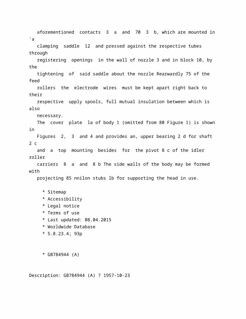
the line 5-5 of Figure 2. The head as shown comprises as its main components a body 1 within which are two drive feed rollers 2 a and 2 b mounted on the same shaft 2 c and a delivery nozzle 3 into which the electrode wires El and E 2 pass from the respective feed rollers and wherein they pick up current through the contacts 3 a and 3 b respectively, from the leads 4 a and 4 b, 'as hereinafter described The shaft 2 c is rotated by an electrode motor 5 of substantially constant speed characteristic through a fixed ratio, speed reduction gearbox 6, neither the motor nor the gear box calling for further description as they are entirely conventional. The electrode wires are electrically separated throughout, both from one another and from the conducting parts of the head, the necessary insulation for ensuring this being shown throughout the drawings thickly cross hatched Thus each of the aforementioned drive feed rollers 2 a 'and 2 b has a metallic wear-resisting rim for engaging the electrode wire and an insulating sleeve portion by whch this rim is mounted on shaft 2 c. Associated with each drive feed roller and freely rotatable in the same plane therewith is an idler roller 6 a, 6 b adjustably urged towards the drive roller by a screwed spring plug 7 a, 7 b acting on a pivotal carrier 8 a, -8 b in which the idler roller is mounted These idler rollers are also formed each with an insulated metallic rim and serve to hold the electrode wires against the respective drive rollers so that they are fed forwardly thereby at a rate dependent onr the peripheral speeds of the latter. As shown, the drive rollers are of differing diameters so that they thus feed the wires at correspondingly different, although constant, rates If, on the other hand, feeding of both Wires at the same rate is required, drive rollers equal in diameter can readily be substituted Within reasonable limits the size of the idler rollers is not material and can be uniform. Forwardly of the feed rollers the electrode wires pass immediately through parallel metal tube-lined passages 9 a and 9 b of an insulating guide block 9 of the body 1 and thence through similarly lined passages 10 a and 10 b of another insulating block 10 within the nozzle 3 In spite of the necessary operating clearance given to the wires by the lining tubes ila and lib of the last mentioned passages, these tubes are sufficiently long to ensure proper electrical contact of the wires therewith, being themselves fed with current through the aforementioned contacts 3 a and 70 3 b, which are mounted in 'a clamping saddle 12 and pressed against the respective tubes through registering openings in the wall of nozzle 3 and in block 10, by the tightening of said saddle about the nozzle Rearwardly 75 of the feed

rollers the electrode wires must be kept apart right back to their respective upply spools, full mutual insulation between which is also necessary. The cover plate la of body 1 (omitted from 80 Figure 1) is shown in Figures 2, 3 and 4 and provides an, upper bearing 2 d for shaft 2 c and a top mounting besides for the pivot 8 c of the idler roller carriers 8 a and 8 b The side walls of the body may be formed with projecting 85 nnilon stubs lb for supporting the head in use.
* Sitemap * Accessibility * Legal notice * Terms of use * Last updated: 08.04.2015 * Worldwide Database * 5.8.23.4; 93p
* GB784944 (A)
Description: GB784944 (A) ? 1957-10-23
Improvements in or relating to stable petroleum distillate fuels
Description of GB784944 (A) Translate this text into Tooltip
[75][(1)__Select language] Translate this text into
The EPO does not accept any responsibility for the accuracy of data and information originating from other authorities than the EPO; in particular, the EPO does not guarantee that they are complete, up-to-date or fit for specific purposes.
-7 2 _ i T PATENT SPECIFICATION 784,944 Date of Application and filing Complete Specification: Nov 26, 1954. % ' B No34326/54. Application made in United States of America on Nov 30, 1953.
Application made in United States of America on Nov 30, 1953, Complete Specification Published: Oct 23, 1957, Index at acceptance:-Class 91, G 1 A 1 L International Classification:-C 1 Og. COMPLETE SPECIFICATION Improvements in or relating to Stable Petroleum Distillate Fuels We, STANDARD OIL COMPANY, a corporation organised under the laws of the State of Indiana, United States of America, of 910, South Michigan Avenue, City of Chicago State of Illinois, United States of America, do hereby declare the invention, foe which we pray that a patent nvay be granted to us, and the method by which it is to be performed, to be particularly described in and by the following statement: - This invention relates to stable petroleum oils and it is particularly concerned with the stabilization of hydrocarbon oils normally susceptible to oxidative deterioration at normal storage temperatures. The deterioration of petroleum fractions, e.g in the distillate oil range, manifests itself through the appearance of color, sediment, etc in the oil Sediment formation is particularly troublesome in oils used as fuels, particularly in the diesel olil and furnace oil range, because it often results in clogging of equipment such as filters, screens, and nozzles. Such deterioration is particularly bad in connection with the use of cracked distillates and since it is common practice to blend substantial portions of such distillates with virgin furnace oil stock to obtain commercial fuel oils, the problem of preventing deterioration of the ultimate commercial product is indeed important Petroleum fractions generally, however, with the possible exception of highly refined lubricating oils, are subject to oxidative de,terioration in storage And the prevention of such deterioration along with provision for finally dispersing the insoluble matter present in an oil are problems of extreme importance to the refiner. It is an object of the present invention to, provide an additive for petroleum oils which will inhibit sedimentation, color formation, and other undesirable deterioration It is another object to disperse, and to thus render harmless, any sludge or color deterioration products occurring tin such oils Still another object is to provide a fuel oil resistant to Price 3 s 6 d l sediment formation and sludging. It is a further object of the present invention to provide corrosion-inhibiting, sludgepreventing additives for fuel oils comprising mixtures of virgin distillate and a cracked oil in the distillate fuel boiling range These and additional objects will be apparent from the following detailed description of the present invention. In accordance with the present invention, sediment formation may be

prevented and oils of good color and overall stability may be assurted by adding to petroleum oils a small amount of at least one polyamino, compound of the hereinafter defined class along with a neutralized reaction product of a phosphorus sulfide and a hydrocarbon More specifically, it has been found that a high degree of stabilization of petroleum fractions normally subject to oxidative deterioration upon storage at normal temperatures may be obtained by adding thereto a small amount of a neutralized reaction product of a phosphorus sulfide and a hydrocarbon, e g that of PS, land a butylene polymer, and at least one N-alkyl alkylene polyamino compound (containing from about 6 to about 30 carbon atoms as the N-alkyl radical) selected from N-alkyl alkylene polyamines containing at least one primary amino nitrogen atom iand carboxylic acid salts thereof These constituents are added in amounts sufficient to inhibit deterioration, e.g generally from 0 001 %' to 0 1 % and preferably from 0 005 to 0 05 % Thus, foir etample, distillate fuel oils containing about 0.005,0 % of an additive comprising 0 004 % of an N-alkyl alkylene polyamine, 0 001 % of an oleic acid salt of such amine, and 0.005 % of a neutralized reaction product of PS, and butylene polymerhave shownstriking stability as compared to the same oils without such additive Not only has such additive shown an outstanding ability to stabilize such oils from deterioration resulting in discoloration and sediment but in addition to be able to disperse any sediment which might form or o 784,944 which might have been present in the oil prior to introducing ithe additive and to impart substantial corrosion inhibiting properties to the oil. Amines suitable for use,in accordance herewith are those N-alkyl alkylene polyamines containing at least one primary amino nitrogen atom Such amines, tin general, may be represented by the structural formula: H 1 R-N(CHI,)m C-(CIHI) N-('1 I 1 I H R' H wherein R represents:an alkyl or substituted alkyl (i e by hydroxy, carboxy, nitro or halo-, groups) hydrocarbon radical containing from about 6 to about 30, and preferably at least about 16 carbon atoms; R' may be hydrogen or an aliphatic hydrocarbon radical, i e ialkyl or cycloalkyl radicals and it is preferably hydrogen; R" may be hydrogen, an,alkylene primary amino radical (i e -(CH 2)NH 2, wherein x is a positive integer from 1 to about 10) or a palyalkylene polyamino radical containing ia primary ammno nitrogen atom; m is a positive integer from 1 to about 10 and preferably 1 or 2; and N may be either 0 or a positive integer from 1 to about 10. Typical examples of such compounds are alkyl derivatives of ethylene diamine, or propylene diamines ( 1,3-diamino propane, 1,2 diamino propane), of diethylene triamine, or triethylene tetramine.
More specifically, there may be employed such amines as N actyl-:ethy;ene diamine, N-n-dodecyl diethylene triamine, N-n-cetylpropylene diamine, N-octadecyl triethylene tetramine, N-hydroxyl dodecyl diethylene triamine, N-chloro-decylet Lhylenediamine, Nbromo octyl ethylene diamine, the various "Duomeens" (products of Armour Chemical Division) which liave the general formula RNHCHZCH 2 CHNH, wherein R may be derived from coconut fatty acid ("Duomeen C "), from tallow fatty acid (" Duomneen T "), from lauric acid (" Duomeen 12 "), or from soya fatty acid (" Duomeen S ") The word "Duomeen" is a registered Trade Mark and the "Duomeens " are industrial or technical grade chemicals with an amine content of approximately 80 % calculated as diamine. The approximate melting ranges for each of the aforementioned "Duomeens" are: "Duomeen C "-20 ' to 24 C, "Duomeen 12 "28 to 32 C, "Duonteen S"-38 to 42 C, and "Duomeen T "-44 to 48 C. It should be understood that the enumeration of the foregoing specific amino-compounds is by way of illustration and not of limitation and that any polyamine falling within the broad definition above recited may be employed. Phosphorus sulfide-hydrocarbon reaction products of the type which may be employed in accordance herewith may be readily obtained by reacting a phosphorus sulfide with a hydrocarbon at a temperature of from about F to about 600 F, and preferably from about 250 ' F to about 500 F, using from about 1 % to about 50 %, and preferably from about 5 % to about 25 %, by weight, of the phosphorus sulfide in the reaction It is advantageous to maintain a non-oxidizing atmosphere, such as for example, an atmosphere of nitrogen above the reaction mixture Usually, it is preferable to use an amount of the phosphorus sulfide that will completely react with the hydrocarbon so that no further purification becomes necessary; however, an excess of phosphorus sulfide can be used and separated from the product by filtration or by dilution with a solvent, such as hexane, filtering and subsequently removing ithe solvent by suitable means, such as by distillation The phosphorus sulfide-hydrocarbon reaction products contain both sulfur and phosphorus The reaction may if desired be carried out in the presence of an additional sulfurizing agent or the phosphorus sulfide-hydrocarben reaction product can be sulfurized. The hydrocarbon constituent of this reaction is preferably a mono-clefin hydrocarbon polymer resulting from the polymerization of low molecular weight monoelefinic hydrocarbnis or isomono-olefinic hydrocarbons, such as propylene butylenes, and amylenes or the copolymers obtained by the polymerization of hydrocarbon mixtures containing iso-monoolefins and mono-olefins or mixtures of olefins in the presence of a catalyst, such as sulfuric acid, phosphoric acid,

boron fluoride, aluminum chloride or other similar halide catalysts of the Friedel-Crafts type. The polymers employed are preferably irono-olefin polymers or mixtures of monoolefin polymers and isomono-olefin polymers having molecular weights ranging from about to about 50,000 or more, and preferably from about 300 to about 10,000 Such polymers can be obtained, for example, by the polymerization in the liquid phase of a hydrocarbon mixture containing mono-olefins and isomono-olefins such as butylene and isobutylene at a temperature of from about 80 ' F. to about 100 F in the presence of a metal halide catalyst of the Friedel-Crafts types such as, for example, boron fluoride and aluminum chloride In the preparation of these polymers there may be employed, for example, a hydrocarbon mixture containing isobutylene, butylenes and butanes recovered from petroleum gases, especially those gtses produced in the cracking of petroleum oils in the manufacture of gasoline. Essentially paraffinic hydrocarbons such as 784,944 bright stock residuums, lubricating oil distillates, petrolatums or paraffin waxes may be used The condensation products of any of the foregoing hydrocarbons or their halogen derivatives, with aromatic hydrocarbons can also be employed. Examples of high molecular weight olefinic hydrocarbons which can be employed as reactants are cetene (C,), ceroitene (C 6), melone (C 30), and mixed high molecular weight alkenes obtained by cracking petroleum oils. Other clefins suitable for the preparation of the herein described phosphorus sulfide reaction products are olefins having at least 20 carbon atoms in the molecule of which from about 12 carbon atoms to about 18 carbon atoms, and preferably iat least 15 carbon atoms, are in a long chain Such olefins can be obtained by the dehydrogenatibn of paraffins, such as by the cracking of paraffin waxes, or by the dehalogenation of alkyl halides, preferably long chain alkyl halides, particularly halogenated paraffin waxes Also, olefins derived from the synthol or hydrocarbon syntheses process may be employed. These arm essentially straight chain ccmpounds varying widely in molecular weight. Also contemplated within the scope of the present invention are the reaction products of a phosphorus sulfide with aromatic hydrocarbons such as benzene, naphthalene, anthracene, toluene and diphenyl and alk Slated aromatic hydrocarbon such as, for example, an alkyl benzene characterized by having at least one alkyl group of at least four carbon atoms, and preferably at least eight carbon atoms such as a long chain paraffin wax. The phosphorus sulfide reactant can be any phosphorus sulfide, such as
for example, P 25, P 4 S,, PS,, and preferably PS,. The phosphorus sulfide-hydrocarbon reaction product normally shows a titratable, acidity which is neutralized by treatment with a basic reagent The phosphorus-sulfide-hydrocarbon reaction product when neutralized with a basic reagent containing a metal constituent is characterized by the presence of retention of the metal constituent of the basic reagent Other metal constituents such as a heavy metal constituent can be introduced into the neutralized product by reacting the same with a salt of the desired heavy metal. The term "neutralized phosphorus sulfidehydrocarbon reaction product" as used herein means a phosphorus sulfide hydrocarbon reaction product having at least about 1 % of its titratable acidity neutralized by the reaction with a basic reagent and includes 'the neutralized phosphorus sulfide-hydrocarbon reaction products containing a metal constituent resulting from said neutralization or resulting from the double decomposition of the phosphorus sulfide-hydrocarbon reaction product treated with a heavy metal salt. The neutralized phosphorus sulfide-hydrocarbon reaction product can be obtained by treating the reaction product with a suitable basic compound such as a hydroxide, carbonate, sulfide, or an oxide of an alkaline earth metal, e g calcium or barium, and preferably 70 the latter, or an alkali metal such as, for example, potassium hydroxide oar sodium hydroxide Other basic reagents can be used such as, for example, 'ammonia or an alkyl or aryl substitute of ammonia such as atnines 75 The products are neutralized by mixing a suitable base (e g a 50 %' solution of KOH) therewith and heating to a temperature in the range of from about 2000 to about 400 F. After the base and phosphorus sulfide hydro 80 carbon reaction product are mixed and neutralized, they are preferably steamed at a temperature of about 400 F to about a half hour The steaming may take place during neutralization 85 The salts of the polyamines which may be employed in accordance herewith may be prepared by reacting, under carefully controlled, non-dehydrating conditions, i e below about F and preferably below about 195 F, 90 a carboxylic acid containing from about 6 to about 20 carbon atoms, and preferably 'at least about 12 carbon atoms, e g hexanoic, non-, anoic, lauric, stearic, oleic, linoleic, linolenic or palmitic, with any of the hereinabove de 95 scribed amnines to obtain either the mono or di substituted acid salts of the amines Care must be taken in the preparation of such salts inasmuch as prolonged exposure to temperaturs higher than about 2000 F results in the 100 formation of amides or even glyoxalidines (if 1,2-substituted polyamines are employed) upon splitting out water Among the very economical, commercially available salts of this type are the olic acid mono and/or di 105 salts of the Duomeens (above
described), particularly of Duomteen T. Whereas the additive of the present invention is generally useful in petroleum distillates, and particularly cracked distillate fuels, 110 it is especially useful in stocks of the type generally referred to as light catalytic cycle oil and fuels containing such an oil Such a catalytic cycle oil is obtained from a catalytic hydrocarbon cracking operation in which a 115 gas oil or heavier hydrocarbons such as reduced crude is cracked at a temperature of about 800 F to about 10500 F at a pressure of about atmospheric to about 50 pounds per square inch sin the presence of suitable 120 catalysts, such as for example silica-magnesia, silica-alumina, and other well-mknown cracking catalysts The product fraction referred to herein is Ithe heavier-than gasoline fraction ordinarily called light gas oil or catalytic light 125 cycle stock A catalytic fight cycle stock of the type particularly suitable for blending with virgin heavy distillates is a fraction having an aromatic content of at least about 40 to about 50/%' and a distillation range be 130 tween about 425 F and about 560 ' F A typical analysis of a suitable light catalytic cycle stock shows the material to be composed substantially of about 10 % normal C,< paraffins, about 45 % of other paraffins and naphthenes, about 5 %' mononuclear aromatics which are mainly mono to hexa alkylated benzenes, and about 40 %' polynuclear aromatics which are mainly alkyl naphthalenes, largely methylated naphthalenes The boiling range of a typical light catalytic cycle stock by A S T M distillation may be approximately:Initial boiling point 10 % over % over % over Maximum boiling point 430 F. 448 F. 478 F. 518 F. 552 F. The boiling range of particular cycle oils may, of course, vary over a considerably wider range, depending upon catalyst, cracking conditions and charge stock Thus, catalytic cycle oils, generally, may boil within the range from about 350 F to about 750 F. It should be understood that the additives of this invention will inhibit oxidative deterioration in normally liquid petroleum fractions which are subject to the same under normal storage conditions Such fractions may be cracked (thermally or catalytically) or virgin or mixtures of these Thus, petroleum distillates generally such as internal combustion engine fuels, furnace oils, burner oils, heater oils, kerosene, heavy industrial residual fuels (e g, Bunker C), jet fuels, blending oils and stripper stocks, may be stabilized in accordance herewith The oils to which the additives of the present invention are added may have been refined by any of the many
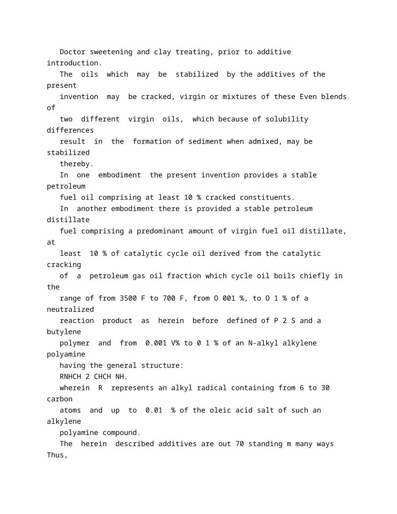
well-lknown techniques, e g, caustic alkali washing, acid treatment, Doctor sweetening and clay treating, prior to additive introduction. The oils which may be stabilized by the additives of the present invention may be cracked, virgin or mixtures of these Even blends of two different virgin oils, which because of solubility differences result in the formation of sediment when admixed, may be stabilized thereby. In one embodiment the present invention provides a stable petroleum fuel oil comprising at least 10 % cracked constituents. In another embodiment there is provided a stable petroleum distillate fuel comprising a predominant amount of virgin fuel oil distillate, at least 10 % of catalytic cycle oil derived from the catalytic cracking of a petroleum gas oil fraction which cycle oil boils chiefly in the range of from 3500 F to 700 F, from O 001 %, to O 1 % of a neutralized reaction product as herein before defined of P 2 S and a butylene polymer and from 0.001 V% to 0 1 % of an N-alkyl alkylene polyamine having the general structure: RNHCH 2 CHCH NH. wherein R represents an alkyl radical containing from 6 to 30 carbon atoms and up to 0.01 % of the oleic acid salt of such an alkylene polyamine compound. The herein described additives are out 70 standing m many ways Thus, the additive imparts rust protection to metal surfaces in contact with the oil inhibits sediment formation, improves filterability by dispersing any sediment formed, inhibits colour degradation and 75 decreases wear of internal combustion engine parts (as demonstrated by the data in Table 3). In Table 1, therefore, laboratory data are set forth which serve to demonstrate many of these improvements The footnotes ( 1 to 4) 80 to Table 1 explain the tests employed and their significance Field tests have borne out the expected superiority of the additive in commercial use Many gallons of potentially sediment-containing fuel oil have been success 85 fully inhibited against this and other results of deterioration by the use of the additive of the present invention in actual commercial shipments Filters which were on the verge of clogging when the use of oil containing such 90 an additive was begun were found to have been substantially de-cclted and unclogged after using the inhibited oil for several months. In those tests where new, clean filters were installed at the outset of the test they were like 95 new several months later whereas other new filters installed at the same time in systems employing uninhibited oil were heavily coated and subject to clogging at any moment. Additional tests of the type set forth in o 100 Table 1 on the same

type fuel oil inhibited with a small amount of a neutralized P S,butylene polymer reaction product and an cleic acid salt of Duomeen T demonstrated the effectiveness of such combination to be 105 about the equal of the polyamine plus the neutralized phosphorus and sulfur containing compound Whereas, a two-component additive, ie polyamine or polyamine oleate plus neutralized P S, butylene polymer, gives ex 110 cellent protection, the combination of polyamine, polyamine salt and neutralized phosphorus sulfide-hydrocarbon reaction product gives a substantially improved result. 784,944 584,944 TABLE 1 KOH-Neutralized Neutralized P 255-butylene P 255-butylene polymer (ca 1000 (ca 1000 mol wt) No additive mol wt) product (a) product (a) plus plus A (b) A (b) B (c) Rust Protection ( 1) ( 1) Water Layer 24 hours severe rust no rust no rust 144,,,,,,,, 300,,,, ,, rust on edges,, ,, ( 2) Oil layer 24 hours,, ,, no rust,, ,, 144,, , , 300 Filterability ( 2) after 50 ml 110 seconds 26 seconds 22 seconds ml 335, 30, 24;, , 400 ml 34,, 26,, J Crucible Mat ( 3) many brown brown tint and few small gray gray specks specks specks Appearance after aging ( 4) cloudy slightly cloudy bright Color after aging ( 4) dark light light Sediment after aging ( 4) very much trace none (a) Employed in amount of 0 005 %. (b) A=Duomeen T (Armour Chemical Division)-employed in an amount of O 05 '%. (c) B=Duomeen T Oleate (Armour Chemical Division)-employed in amount of 0.001,%. ( 1) 50 milliliter samples of furnace oil were filtered into bottles and doped with additive Bright steel strips were immersed in the oil for 5 minutes, then withdrawn Twentyfive milliliters of water were added to the bottles, and the bottles were thoroughly shaken The steel strips were then reimmersed and left to stand in the open bottles for 144 hours The strips were then withdrawn, dipped in mineral oil, allowed to drain, and hung in room air The strips were examined after 24, after 144, land after 300 hours. ( 2) 500 milliliter samples of furnace oil, with and without additive, were aged in open bottles in an oven for 20 hours at about 220 F The samples were allowed to cool, and then filtered through 1 square centimeter of filter paper having a pore size of 10 microns, using a constant head of 12 inches of oil. The time necessary to collect successive 50 ml increments of oil was recorded The time required for the first, fourth and eighth 50 mil. portions is given above -The high sediment and gum content oil becomes progressively harder to filter whereas the time for those containing the additive change very lilttle from start to finish. ( 3) 500 milliliter samples of furnace oil, with and without additive,
were shaken from 500 ml of tap water in a separatory funnel. The oil and water layers were allowed to separate for 30 minutes; the free water was then drawn off, and theinterfacial rag and the oil layer were filtered through a medium porosity sintered glass crucible The color and nature of the mat retained in the crucible indicate the tendency of tha oil to sludge after contact with water The lighter the mat the less the sludging tendency. ( 4) At the completion of the filtration, data for which are set forth above under "filterability", the filtered samples were returned to bottles and stoppered and then allowed to S 784,944 stand art room temperatures for seven days. The results given are a result of visual examination. Run with different sample of control oil but under essentially identical conditions. Accordingly, it should be understood that whereas either of such twa component additives will given excellent results in accordance herewith it ds preferred to employ all three, i e polyamine, polyamine-carboxylic acid salt,and neutralized phosphorus sullfidehydrocarbon reaction product Of the two component additives, it is preferred to employ that comprising the polyamine rather than salt thereof. In Table 2 are set forth data demonstrating the effectiveness of a rather wide variety of amines and phosphorus-sulfide hydrocarbon reaction products These data are of a qualitative nature 'and clearly demonstrate on a laboratory scale the ability of the additives of the present invention to inhibit color degradation and sediment formation, in a furnace oil comprising 60 % virgin distillate and 40 % fresh, caustic washed catalytic cycle oil Data are included which compare the effectiveness of the herein disclosed polyamines with other amines which have heretofore been added to petroleum oils for various purposes The data in Table 2 with the exception of the appearance of the crucible mat {are based on the appearance of a furnace oil having the same composition as that employed in the tests recorded in Table'l 1, containing the additives indicated, after being heated for 20 hours at 200 F and then held at room temperature for an additional 48 hours The crucible data are obtained on the same oils in accordance with the test described in footnote ( 3) of Table 1 prior to heating the oils for 20 hours at 200 F. TABLE 2 P 255 Butylene Polymer (ca 1000 mol wt) Reaction Prod. Amount Appearance of "Duomeen T Crucible after Oleate" Test (c) Color Brightness Sediment 1 (Control) Deep purple flecks Duomeen T 4, C 4 Duomeen C Duomeen T 6 Duomeen S 7 Duomeen 12 8 N-n-Dodecylethylenediamine 9 N-n-lauryl diethylenediamine Duomeen T 11

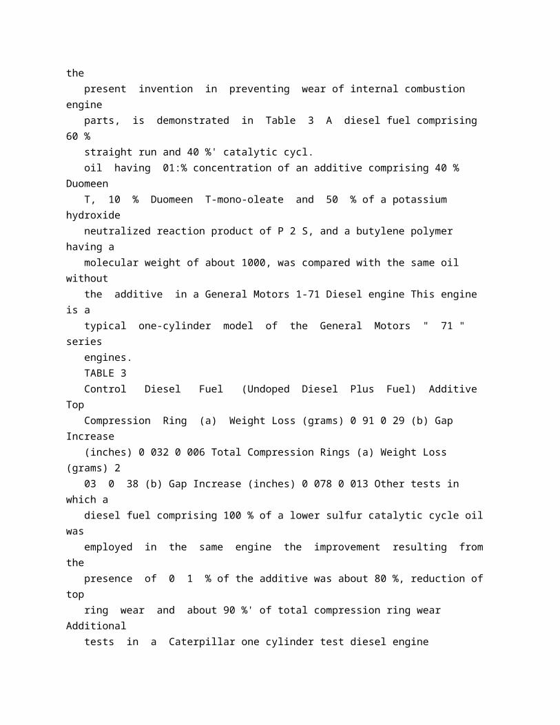
Phenylene Diamine 12 N-Hydroxy dodecyldiethylenetriamine 004 004 004 004 004 004 A (a) B (b) A B A A A 004 A 004 004 A A A co 005 001 001 001 001 001 001 001 001 Lt Pink Cast Gray Cast Gray Brown Cast Deep Gray Cast Pink Cast Pink Cast Chocolate Mat Tan Gray Cast Dark Light ,1 , , , ,3 , V Cloudy Much Clear None SI, Cloudy,, V Clear,, Clear,, Cloudy Moderate , 51 Cloudy , V Clear Dark Cloudy Light 51 Cloudy Trace None Much Trace (a) -A = KOH neutralized and steamed (at 400 F) reaction product of P 255 and butylene polymer. (b) B Ba(OH)2 neutralized and steamed (at 400 F) reaction product of P 25, and butylene polymer. (c) See footnote ( 3) to Table 1 (supra) for explanation of test resulting in these observations. Example Amine Amount (DO,, 00 4.P The surprising ability of additives of the present invention in preventing wear of internal combustion engine parts, is demonstrated in Table 3 A diesel fuel comprising 60 % straight run and 40 %' catalytic cycl. oil having 01:% concentration of an additive comprising 40 % Duomeen T, 10 % Duomeen T-mono-oleate and 50 % of a potassium hydroxide neutralized reaction product of P 2 S, and a butylene polymer having a molecular weight of about 1000, was compared with the same oil without the additive in a General Motors 1-71 Diesel engine This engine is a typical one-cylinder model of the General Motors " 71 " series engines. TABLE 3 Control Diesel Fuel (Undoped Diesel Plus Fuel) Additive Top Compression Ring (a) Weight Loss (grams) 0 91 0 29 (b) Gap Increase (inches) 0 032 0 006 Total Compression Rings (a) Weight Loss (grams) 2 03 0 38 (b) Gap Increase (inches) 0 078 0 013 Other tests in which a diesel fuel comprising 100 % of a lower sulfur catalytic cycle oil was employed in the same engine the improvement resulting from the presence of 0 1 % of the additive was about 80 %, reduction of top ring wear and about 90 %' of total compression ring wear Additional tests in a Caterpillar one cylinder test diesel engine demonstrated much the same improvement in wear characteristics. As indicated above, the additives of the present invention are useful in straight run stocks (virgin) and blends of differest virgin stocks. Thus, as shown in Table 4, the improved 30 color inhibition in such oils when employing an additive of the present invention is substantial. TABLE 4 Color (Saybolt) Initial Aged ( 4) Control (A) ( 1) + 13 -2 ,, + 0 01 % of Additive ( 2) 13 + 10 , + 0 0025,,,, + 13 + 10 , + O 001,,,, 13 + 8 Control (B) ( 3) 13 -6 + 0 0025 % of Additive ( 2) + 13 + 5 ( 1) Blend
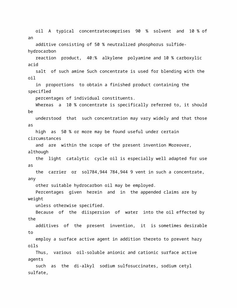
of Cu Cl, sweetened Mid continent virgin heater oil distillate and sulfuric acid treated West Texas virgin heater oil distillate. ( 2) 50 % KOH neutralized reaction product of PSS, and butylene polymer of about 1000 molecular weight, 40 % of Duomeen T and 10 % of Duomeen T monooleate. ( 3) Sulfuric acid treated West Texas heater oil distillate. ( 4) Heated for one hour at 290 F and observed The introduction of the additive of the present invention to distillate fuels is greatly facilitated by the use of concentrated oil solutions of such additives It has, for example, been found especially desirable to use a 10 % concentrate of -such additive in,an oil such as light catalytic cycle oil A typical concentratecomprises 90 % solvent and 10 % of an additive consisting of 50 % neutralized phosphorus sulfide-hydrocarbon reaction product, 40:% alkylene polyamine and 10 % carboxylic acid salt of such amine Such concentrate is used for blending with the oil in proportions to obtain a finished product containing the specifled percentages of individual constituents. Whereas a 10 % concentrate is specifically referred to, it should be understood that such concentration may vary widely and that those as high as 50 % or more may be found useful under certain circumstances and are within the scope of the present invention Moreover, although the light catalytic cycle oil is especially well adapted for use as the carrier or sol784,944 784,944 9 vent in such a concentrate, any other suitable hydrocarbon oil may be employed. Percentages given herein and in the appended claims are by weight unless otherwise specified. Because of the diispersion of water into the oil effected by the additives of the present invention, it is sometimes desirable to employ a surface active agent in addition thereto to prevent hazy oils Thus, various oil-soluble anionic and cationic surface active agents such as the di-alkyl sodium sulfosuccinates, sodium cetyl sulfate, petroleum sulfonates, cetyl pyridinium chloride and octadecylamine acetate, may be employed Such surface active agents will vary in effectiveness with the particular oil, the amount of water, the physical state of the water in the oil, i e whether it is suspended or dissolved, the range of temperature over which the oil may be stored, but in general tare effective in amounts between about 0.001 to about 0 05 % by volume based on total oil Greater and lesser an:ounts may be found useful under certain circumstances Thus haze was successfully inhibited in a fuel oil composition comprising an oil consisting of % virgin furnace oil distillate and 401 % catalytic cycle oil which had been stabilized against color and sediment formation with 0 01 % of an additive comprising 0 005 %' of neutralized P 2 S, butylene polymer reaction product, 0 004 % of Duomeen T and 0 0011 %.
of Duomeen T-monooleate, by the addition of 0.002 i% by volume of sodium; mahogany soap derived from the fuming sulfuric acid treatment of a hydrocarbon oil in the preparation of a Technical White Oil In place of the sodium mahogany soap of the above example, other surface active agents of the type above enumerated may likewise be employed. In the appended claims the term "N-alkyl radical" wherever employed shall include alkyl radicals of the type described and substituted alkyl radicals, i e substituted by groups such as halo or hydroxy.
* Sitemap * Accessibility * Legal notice * Terms of use * Last updated: 08.04.2015 * Worldwide Database * 5.8.23.4; 93p
* GB784945 (A)
Description: GB784945 (A) ? 1957-10-23
Improvements in or relating to internal combustion engines
Description of GB784945 (A)
PA Tt N SPECIFICATIOI my Date of filing Complete Specification Jan 12, 1956. Application Date Jan 15, 1955. No 1286155. Complete Specification Published Oct 23, 1957. Index at Acceptance:-Class 7 ( 6), B 2 Q 5 (A: B: F). International Classification: -FO 2 f. COMPLETE SPECIFICATION Improvements in or relating to Internal Combustion Engines I, JOHN HAY, A M I Mech E, (of British Nationality), of " Southlands ", Sea Lane, Ferring, near Worthing, Sussex, do hereby declare the invention, for which I pray that a patent may be granted to me, and the method by which it is to be performed, to be particularly described in and by the following statement: -
In giving a description of this invention it is necessary to draw attention in the first instance to the fact that the reciprocating internal combustion engine (as designed at the present time) suffers from an inherent defect in that its expansion or working stroke is no longer than its compression stroke. Many attempts have been made to design a differential stroke engine, i e, an engine in which the piston makes, say, one long stroke, followed by a short stroke. One case of an engine of this kind was described in " Engineering " on November 11th, 1927, page 613 but naturally, as one would expect, the mechanical complication and increased number of moving parts involved was somewhat grotesque The chief point which emerged from the published tests was the impressive fact that the fuel consumption was reduced from approximately 5 7 lbs per B.H P hour, to 3 7 lbs per bralke horsepower hour, as compared to the consumption of an engine of ordinary four-stroke design. My proposals in this invention are really extremely simple, although the results might prove extremely important, as by the use of the valves hereinafter described it is possible to obtain the functional characteristic of a differential stroke engine without any increase in the number and complication of the main components. The functional characteristics of a differential stroke engine may be assumed to be for the purpose of this particular application:An engine in which the working medium or gases are enabled to expand over a longer period of time and distance than that occupied by the preceding compression period. The type of parallel cylindrical valves described in my prior Patent 17865/10 have been l.Pice 3 s 6 d l found useless in practice owing to leakage My new design of valve put forward in this application is tapered in that region containing the inlet, exhaust, or scavenging air ports. The cylinder head or cylinder barrel is also tapered to receive the similarly tapered valve or valves, all as shown on the accompanying drawings. This application also covers the use of this type of valve in engines working on all cycles (when practically applicable) in addition to the ordinary four-stroke engine as used on motor vehicles. The kind of valves described in Patent 17865/10 really only had this last mentioned type of engine in view, as it was not foreseen by me at that date that designers would one day be faced with the problem of arranging for the inlet of scavenging air or egress of exhaust gases of cylinders of dimensions capable of developing approximately 1000 h p. per cylinder.
I should like to make it clearly understood that I consider one of the most important applications of this valve gear is to large engines of the marine type both double acting two-stroke and single acting two-stroke. My idea being to render unnecessary exhaust pistons and eccentrics for actuating them, which are now thought necessary simply to open and close a ring of ports in the cylinder barrel. Also this valve gear may be used on engines, both single and double acting, two or fourstroke now being manufactured by continental makers, my idea being to render the B shaped rotary valve at present being fitted in the exhaust port, unnecessary. It should be clearly understood that the application of an oscillating yalve according to the invention (having one conical and two cylindrical portions) would usually only require one such valve to effect the opening and closing of a ring of ports in the cylinder barrel, but two valves can be fitted (one outside the other) where great speed of port opening is required. Twin valves are necessary in order to 784,94 784,945 obtain satisfactory port opening and closing movements for the ordinary four-stroke cycle motor car engine. In the accompanying drawings:Fig 1 shows a four-stroke cycle internal combustion engine forming one embodiment of the invention. Fig 2 is a section on the line XX of Fig 1. Fig 3 shows a second embodiment of the invention. It should be clearly understood that the valve arrangement shown in Figs 1 and 2 portrays the application of this invention as it might be applied to the ordinary motor car engine, this arrangement has nothing to do with the question of a differential stroke engine. Fig 3 shows how this invention can be applied so to produce the functional characteristics of a differential stroke engine (as defined on page 2) In Figs 1 and 2 of the complete specification A and B are oscillating valves each having cylindrical end portions separated by a conical portion, the control ports of the valve being formed in the conical portion thereof. C=Cylinder head casting. D= Outer head or valve casing. E=Cylinder head cover. F and G=Circular valve driving rings, castellated on lower edge, to fit castellations on upper edge of valves These driving rings have actuating arms to which rods actuated by eccentrics are attached, vwhereby the valves are oscillated. H=High pressure joint I = Cylinder barrel J Cylinder inlet and exhaust ports controlled by the corresponding ports in the conical portions of the valves A, B K=Part of water jacket L=Low pressure joint M =Low
pressure joint. This design provides ready access to the valves A and B for inspection, etc, when the cylinder cover E and the outer head or valve casing D are removed. In this particular design shown in Figs 1 and 2 it will be noted that the water jacket is external to the valves, this of course enables the valve diameter to be reduced from what it would have had to be if the water jacket had run up inside the valves (i e, between the valves and the cylinder head casting). It is desired to retain in this patent application the very important design feature, i e, that the water jacket may be designed to run up internally to the valves, water passages in the cylinder head port bars making connection between the cylinder head water jacket and the main cylinder barrel jacket as described in my prior Patent 17865/10. The manner in which the valves A and B cooperate to control the ports is as follows: In the case of the ordinary four-stroke engine (Figs 1 and 2) the valves are oscillated by two small eccentrics situated on a vertical shaft (not shown on Figs 1 and 2) but similar to that shown on the right hand side of the differential stroke application shown in Fig 3. It will be found that if these two small 70 eccentrics are placed on the vertical shaft with a relative displacement to one another of approximately 70 % and appropriate ports are then cut in the valves, the resulting opening and closing periods for both inlet side and 75 exhaust side form a very fair approximation of the valve timing in a modern engine fitted with ordinary mushroom valves actuated by the orthodox camshaft. The description and action of the engine 80 shown in Fig 3 of the complete specification is as follows:It should be clearly understood that the design shown is intended to provide differential stroke characteristics in that the period 85 allotted for expansion is greater than that allotted for compression. The engine is two-stroke (i e, one power impulse at every down stroke) and is superficially like an ordinary heavy marine engine 90 of the two-stroke type. On closer inspection it will be noticed that the cylinder barrel is provided with three rings of ports, one at the top end, one at the bottom end, and another very approximately at mid 95 stroke The top ring of exhaust ports (E, Fig 3) sheet 1 are controlled by a yalve " A " similar to the valve A or B shown in Fig 1. The mid-ring of secondary air ports J, Fig 3, Sheet 1, are controlled by a similar valve 100 "B " The lowest ring of ports (primarily air scavenge) C, Fig 3, Sheet 1, is controlled by the main piston During the working or power stroke, the valve B, Fig 3, remains closed during
the entire downward stroke of 105 the piston, which finally uncovers the ring of scavenging air ports C, Fig 3. At or about this period in the cycle, the exhaust valve A at the cylinder head opens, so that straight through, or end-to-end 110 scavenging is obtained The exhaust valve A would remain open while the piston is making the first portion of its return stroke, and the valve "B" opens soon after the exhaust valve " A " has closed and high pres 115 sure air is admitted to the cylinder just before the piston on its upward stroke closes the secondary air ports " J ". The distance between the primary scavenging air ports C, Fig 3, at the extreme lower 120 end of the cylinder, and the secondary air ports J, Fig 3, controlled by the valve B situated very aproximately at about mid-stroke of the main engine piston is, of course, at the discretion of the designer, but judging from 125 the published trial results of large marine engines in which the scavenging air and exhaust belts are in close proximity, this distance can have an altogether unexpected influence on the performance of the engine 130 784,945 In this particular design it cannot be said that these two port belts are really in close proximity, but the designed distance between them would naturally govern the expansion ratio it was wished to use in the working cycle of any particular engine Reverting again to the cycle of operations I am outlining, it is contemplated that the air pressure supplied to the middle belt (J, Fig 3) of ports would not necessarily be of the same order as that used in the primary scavenging belt, indeed, it would, in all likelihood, be very considerably higher, so as to supercharge the main cylinder. In other words, the air pressure in the main cylinder would be under external control at the period of the upward stroke immediately preceding the final closing of the secondary air ports by the main piston. In view of the above facts, the ultimate or terminal degree of the main cylinder compression could be varied at will Moreover, the working gases expand over a longer period of time than that occupied by the preceding compression period due to the valve " B" remaining closed on the downstroke and the valves A and B opening for a portion of the up stroke of the piston.
* Sitemap * Accessibility * Legal notice * Terms of use * Last updated: 08.04.2015 * Worldwide Database * 5.8.23.4; 93p
* GB784946 (A)
Description: GB784946 (A) ? 1957-10-23
Process of decorating textile materials
Description of GB784946 (A) Translate this text into Tooltip
[75][(1)__Select language] Translate this text into
The EPO does not accept any responsibility for the accuracy of data and information originating from other authorities than the EPO; in particular, the EPO does not guarantee that they are complete, up-to-date or fit for specific purposes.
PATENT SPECIFICATION 784,946 Date of Application and filing Complete Specification: Jan 18, 1955. No 1537/55. Application made in Germany on Jan 18, 1954. (Patent of Addition to No 729,122, dated Oct 24, 1951). Complete Specification Published: Oct 23, 1957. Index at acceptance:-Classes 2 ( 6), P 2 A, P 2 D( 1 A: 8), P 2 K( 7: 8), P 2 P( 1 E 5: 2 A 1: 2 A 4: 4 A), P 2 T 2 A, P 7 A, P 7 D( 2 A 1:8), P 7 K( 2:8), P 7 P( 1 E 5:2 A 1:2 A 4:4 A), P 7 T 2 A, P 8 A, P 8 D( 1 A: 2 A: 3 A: 8), P 8 K( 2: 7:10), P 8 P( 1 E 5: 2 A 1: 2 A 4: 4 A), P 8 T 2 A, Pi 10 A, P 10 (D 2 A: K 8: P 2 A 4: T 2 A); and 15 ( 2), B 2 C 1 A 3; B 2 C 2 (B: C: D 1 A: D 1 B: F), B 25. International Classification:-C 08 f D 06 p. COMPLETE SPECIFICATION Process of Decorating Textile Materials We, FARBENFABRIKEN BAYER ARTIENGESELLSCHAFT, a body corporate organised under the laws of Germany, of Leverkusen, Germany, do hereby declare the invention, for which we pray that a patent may be granted to us, and the method by which it is to be performed, to be particularly described in and by the following statement -
In Specification Serial No 729,122 there is claimed a process for decorating, e g, printing or padding, textile materials which comprises applying to such material an emulsion of a vinyl or divinyl polymer or copolymer and a high molecular basic compound which, as such or as a salt, is soluble or emulsifiable in water, and, if the basic compound is not a cross-linking agent as such, causing to react therewith, on the material, a compound containing two or more groups, capable of reacting with the basic groups of the high molecular compound, at ordinary temperature or, if necessary, at an elevated temperature. The present invention is an improvement in respect of said process and consists in using basic high molecular weight compounds containing amino and/or imino groups and reactive epoxy groups as compounds containing two or more groups, capable of reacting with the basic groups of the high molecular compound, at ordinary temperature or, if necessary, at elevated temperature Such compounds include condensation products which can be obtained from di or poly-amrnines by the action of epihalohydrines or di-halohydrines As di or poly-amines there can be used, for example, tetramethylene diamine, hexamethylene diamine, dipropylene triamine, ?Y, l diaminopropyl methylamine, y,7 diaminopropyl ether, diaminopropyl tetramethylene diamine, bis (y aminopropyl)piperazine, or N ( 1,6 hexanediamine) 3pyrrolidone, -_ lPrice H 2 N C Ha C Ha C H CH CHL CHA-NHZ H 2 C-LL 1 The preparation of these condensation products is described in Specification Serial No. 774,101 The reaction of di or poly-amines with epichlorohydrin or dichlorohydrin is carried out with such proportions of the reagents and under such conditions that not all of the hydrogen atoms available on the nitrogen are replaced This ensures the possibility of further cross-linking of the products obtained. It is possible by appropriately selecting the p H-value, concentration, temperature and mode of reaction to prepare condensation products having a wide range of viscosities The condensation reaction can be interrupted at any time by the addition of acid This addition of acid acts also to stabilise the condensation products The condensation products react, when heated to temperature of about C, due to their content of epoxy groups as well as of -NH and/or NH -groups, with self-cross-linking to form water insoluble products. The aforesaid basic high molecular weight compounds containing epoxy groups possess film-forming properties and act not only by self-cross-linking but also by cross-linking the other basic higher molecular weight compounds contained in the composition applied to the textiles The compounds containing epoxy groups are, therefore, binding
agents (e.g, for pigments) and cross-linking agents at the same time. The employment of such cross-linking agents which act at the same time as binding agents has the advantage over the majority of other cross-linking agents in that on account of their self-cross-linking capacity they can be applied in excess When the usual watersoluble cross-linking agents non-volatile on drying at 100-150 C, are used in excess they remain partly unchanged in the film after fixation and thus cause a low resistance to water In spite of this disadvantage, a small excess is preferred in practice, because even a small deficit of cross-linking agents would produce even less favourable results Though an excess does not become apparent in the process according to the present invention, it is best to avoid the application of too great an excess in certain combinations in pigment printing because otherwise the shade may sometimes become dull. Moreover, in application, the condensation products containing epoxy groups have the great advantage over most other cross-linking agents in that they cross-link very rapidly on drying, on the one hand, and in that they are practically stable in aqueous acidic solution up to temperatures of about 50 C, on the other hand An extremely prolonged stability of the printing pastes is thus obtained. Compared with other cross-linking agents, those used in the present invention have a greater inherent viscosity and therefore printing pastes produced therewith do not need any thickening agents Therefore a better feel and a better fastness to washing of the printed textiles are obtained. The following Examples are given for the purpose of illustrating the invention, the parts and percentage concentrations mentioned being by weight: EXAMPLE 1. In 150 parts of a 3 % aqueous solution of the sodium salts of sulphonated long chain paraffins is dissolved 0 7 part of the sodium salts of sulphinated long chain paraffins The mixture is emulsified with 50 parts of styrene, 48 parts of acrylic acid butyl ester and 2 parts of acrylic acid The emulsion is rendered acid with 2 parts of IN sulphuric acid and then polymerised at 30 C until the reaction is practically complete An emulsion is thus obtained having about 40 % of solids In order to increase the pigment compatibility and the mechanical stability, this emulsion is treated with 12 5 parts of the conversion product of cetyl alcohol with ethylene oxide. 205 Parts of this latex are mixed with parts of a 10 % aqueous solution ( 800 cp/25 C) of the acetate of a basic polyurea produced from 0.05 mol of diethylene triamine Z 0 95 mol of 7,y-diaminopropylmethylamine 1.01 mol of hexane diisocyanate parts of a 30 %' aqueous solution of the hydrochloride of a basic epoxy produced from 0.28 mol of dipropylene triamine 1.00 mol of

epichlorohydrin and 15 parts of 50 % acetic acid, and the whole is stirred until homogeneous; whereupon parts of a 20 % red pigment paste are stirred in It is then treated with parts of urea parts of isooctyl alcohol parts of methyl cellulose ( 70:1000) 235 parts of water; making a total of 1000 parts. Instead of the basic polymer from dipropylene triamine and epichlorohydrin used as cross-linking agent, there can be used the polymer formed from /,,y'-diamino-propylmethylamine and epichlorohydrin. The above mixture yields a very satisfactorily stable and pliable printing paste which can easily be rinsed off with water from the printing roller or film-printing screens The printing paste is printed on to cotton or staple fibre in the usual manner The after-treatment consists for cotton in drying at 80 C, and for other kinds of fibres in heating at 110-130 C after normal drying. The prints obtained on cotton, staple fibre or rayon excel in depth of colour, brightness of shade, very good fastness to drying and good fastness to wet rubbing,-very good to rubbing by hand in laundering-very good fastness to boiling soda and to light. EXAMPLE 2. 1 Part of the sodium salts of sulphonated 100 long chain paraffins, 12 5 parts of the reaction product of cetyl alcohol and ethylene oxide, 0.7 part of the sodium salt of sulphinated long chain paraffins and 0 15 part of potassium persulphate are dissolved in 150 parts of 105 water. 0.4 Part of di-iso-propyl xanthogenic disulphide, 40 parts of butadiene, 40 parts of acrylonitrile and 20 parts of styrene are emulsified in this solution in a pressure vessel 110 The emulsion is rendered acid with 2 parts of IN sulphuric acid and polymerised under its own pressure until a yield of about 100 per cent is obtained The resulting 40 % emulsion is emulsified with 3 parts of the formaldehyde 115 conversion product of o-cyclohexyl-p-cresol as anti-ageing agent: -GO H W HO Ca 784,946 611 (viscosity value zq= 245 x 10-3) produced from diaminopropyl tetramethylene diamine and oxalic ester, and the whole is homogenised Then are added parts of glycerol parts of methyl cellulose ( 70:1000) parts of a 15 % aqueous paste of copper phthalocyanine parts of a 15 % aqueous solution of the hydrochloride of a basic polymer produced from 0.22 mol of diaminopropyl tetramethylene diamine and 1.00 mol of epichlorohydrin and 285 parts of water, making a total of 1000 parts. The property of being rinsed off the printing roller and the stability of the printing paste is similar to those according to Example 1 The carrying out of the process is effected similarly to that in Example 1 Prints are obtained on cotton, staple fibre and rayon which excel in

depth of colour, brightness of shades, very good fastness to drying and to wet rubbing.
* Sitemap * Accessibility * Legal notice * Terms of use * Last updated: 08.04.2015 * Worldwide Database * 5.8.23.4; 93p
* GB784947 (A)
Description: GB784947 (A) ? 1957-10-23
Improvements in or relating to an improved burner and processes forproducing carbonblack
Description of GB784947 (A)
PATENT SPECIFICATION 784,947 Date of Application and filing Complete Specification: Feb 1, 1955. No 2950155. Application made in United States of America on Feb 8, 1954. Complete Specification Published: Oct 23, 1957. Index at acceptance:-Classes 75 ( 1), TN 3, TP 3 D; and 90, K 4. International Classifieation:-CO 1 b, F 23 f. COMPLETE SPECIFICATION Improvements in or relating to an Improved Burner and Processes for Producing Carbon Black We, PHILLIPS PETROLEUM COMPANY, a corporation organised under the laws of the State of Delaware, United States of America, of Bartlesville, Oklahoma, United States of -5 America, do hereby declare the invention, for which we pray that a patent may be granted to us, and the method by which it is to be performed, to be particularly described in and by the following statement:- This invention relates to an apparatus and to a process for the production of carbon black. It is known in the art to produce carbon black by reacting a

hydrocarbon thermally by virtue of heat imparted to said hydrocarbon from a hot combustion gas Such a process is described in U K Patent Specification 679,818 Such a process utilizes a reactor comprising a combustion zone positioned coaxially and in open communication with a reaction zone of smaller diameter than said combustion zone A fuel and an oxidant in combustible proportions are introduced at high velocity, tangentially, into said combustion zone and resulting combustion gas travels in a spiral path toward the axis of said zone Combustion of the fuel is completed near the periphery of the combustion zone The combustion gas travels, from the combustion zone, in a helical path into the reaction zone A reactant capable of being converted to carbon black is introduced longitudinally into the combustion zone and is reacted in, the reaction zone by virtue of heat directly imparted thereto by the combustion gas. This invention provides an apparatus and a method whereby combustion of the tangential fuel gas is effected in an improved manner. According to the invention there is provided a burner for use in a carbon black production reactor comprising an inner conduit longitudinally positioned within an outer conduit, orifice means in the outlet end of lPrice 3/61,. said outer conduit; closure means at the corresponding end of said inner conduit; a plurality of peripheral openings in said inner conduit adjacent said closure means; and at least one other peripheral opening in at least 50 one of said conduits positioned upstream from the orifice means. The invention also includes a carbon black production reactor comprising a substantially cylindrical reaction chamber coaxial with 55 adjacent and in open communication with a substantially cylindrical combustion chamber having a larger diameter than said reaction chamber, an axial inlet to said combustion chamber, at least one tangential inlet 60 to said combustion chamber and a burner according to the preceding paragraph positioned within said tangential inlet. Finally the invention provides a process wherein carbon black is produced by tangen 65 tially introducing a fuel and a free oxygencontaining gas in combustible proportions into a substantially cylindrical combustion zone, completing the combustion of said fuel in a peripheral part of said zone, passing re 70 sulting combustion gas in a helical path into a substantially cylindrical reaction zone coaxially positioned adjacent said combustion zone and in open communication therewith, said reaction zone having a smaller diameter 75 than said combustion zone, injecting a reactant hydrocarbon axially into said combustion zone, and reacting said reactant hydrocarbon to form carbon black which is recovered as a product, which is character
80 ised by mixing said fuel with -said free oxygen-containing gas during said tangential introduction in a zone of turbulent mixing maintained adjacent the outlets of coaxially disposed conduits supplying said fuel and 85 said oxygen-containing gas, and causing part of the contents of at least one of said conduits to flow out of the interior of its conduit and along the exterior thereof at a point upstream from said zone of turbulent 90 : is 784,947 mixing. In one modification the burner comprises the elements set forth above, and the inner conduit is provided with a group of peripheral openings positioned upstream from the openings adjacent the closed end Said openings can be arranged in staggered relationship with the openings adjacent the closed end; thus, each of said openings can be longitudinally non-aligned with respect to each of the openings adjacent the closed end. In another embodiment of the invention, the burner comprises the inner conduit and the outer conduit as set forth above, and the outer conduit is provided with a group of circumferentially spaced peripheral openings upstream from the openings in the inner conduit The inner conduit can be provided with additional peripheral openings upstream from the peripheral openings adjacent the closure end thereof, or such additional openings can be omitted. According to another embodiment of the invention, a burner of the type above described, utilized in a carbon black apparatus of the type above described, is protected from the effects of the high temperatures produced in said apparatus by causing part of the air which is supplied through the outer conduit to pass along the outside of said conduit, whereby a cooling effect is provided. By the process of the invention, the fuel supplied to a carbon black process of the type described may be mixed with the free oxygen-containing gas in two stages, the first stage occurring upstream of a zone of turbulent mixing which zone exists adjacent the outlet ends of the conduits supplying the fuel and the free oxygen-containing gas. In the drawings, Fig 1 is an elevational flow diagram, partly in section, of a process in connection with which the present invention is utilized; Fig 2 is a sectional view taken along line 2-2 of Fig 1; Fig 3 is an enlarged sectional view of the tangential burner diagrammatically shown in Fig 2; Fig 4 is a sectional view taken along line 4-4 of Fig 3; Fig 5 is a sectional elevation of a modified burner according to this invention; Fig 6 is a sectional view taken along line 6-6 of Fig 5; Fig 7 is a sectional elevation of another modified burner according to this invention; Fig 8 is a sectional view taken along 8-8 of Fig 7; Fig 9 is a sectional view taken along line 9-9 of Fig 7.
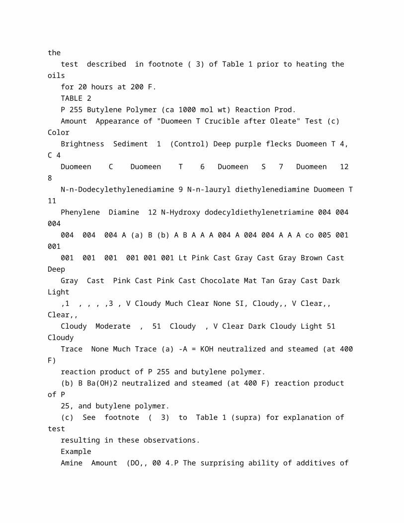
Fig 1 illustrates an apparatus and process of the type described in U K Patent 679,818, previously cited, and illustrates the use of one embodiment of the present invention in connection with such a process The process described in the cited patent is known as a tangential flame process of the precombustion type. As shown in Fig 1, there is provided a 70 carbon black reactor designated generally as 7 and comprising an outer metal shell 8, insulation 9, and refractory liner 10 The reactor contains combustion zone 11 and reaction zone 12 These zones are coaxially 75 positioned in open communication with each other, and are generally cylindrical Combustion zone 11 is of greater diameter than reaction zone 12 and preferably has a shorter length than zone 12 and a length shorter 80 than its own diameter. A reactant, which is ordinarily a liquid hydrocarbon and preferably an aromatic gas oil, but which may be sither liquid or gaseous, enters the system through inlet 2 and is 85 preheated, and preferably vaporized, in heater 3 The heated oil passes to axially positioned inlet 4 and is axially injected into the furnace 7 A small amount of air enters through inlet 5 into annular inlet 6, which 90 surrounds the oil inlet 4 Only sufficient air is added at this point to prevent deposition of carbon around the outlet of oil injector 4. Simultaneously, as shown in Fig 2, air is injected through inlets 20 and 23 and a fuel, 95 such as natural gas, is injected through inlet 22 As shown in Fig 2, combustion zone 11 is provided with tangential inlets or tunnels 13 Positioned within each of said tunnels is a burner according to this invention 100 The burner comprises air inlet 20 and gas inlet 21 which is preferably positioned coaxially within conduit 20 Air and fuel gas enter combustion zone 11 at a very high velocity Combustion is ordinarily com 105 pleted within tunnels 13 but may continue to some extent beyond said tunnels The combustion of the fuel gas at high linear velocity produces a combustion gas which moves spirally inward toward the axis of 110 chamber 11 The hot combustion gas then proceeds in a helical path into reaction zone 12, thus heating reaction zone 12 to a carbon black-forming temperature The axially introduced oil is thermally reacted in chamber 115 12 to form high-quality carbon black in high yields A resulting mixture of carbon black anl resulting gas passes from reaction zone 12 into pipe 14 The reaction mixture is preferably initially cooled to a temperature 120 below 1250 F by means of water directly injected through quench inlet 15 The resulting mixture proceeds through pipe 14 and can be further cooled therein by exposing an uninsulated section of pipe 14 to the atmos 125 phere or by the use of a water jacket or additional quench inlets, not shown The cooled mixture of carbon black and combustion gas passes to gas-solids separation zone 18, which can be one or more
cyclone sepa 130 784,9-47 rators, Cottrell precipitators, bag filters, or any combination of these, or other known equipment for the separation of solids from gases Combustion gas is withdrawn through outlet 16 and product carbon black is withdrawn through outlet 17. Fig 3 shows structural details of one modification of a burner according to this invention, said burner being positioned in tunnel 1013 of the carbon black reactor, as indicated in Fig 2 An air tube or blast tube 20 is provided with an annular orifice plate 25, which can be secured to tube 20 by any suitable means such as welding Flange 30 is provided for connection to an air pipe 23, as shown in Fig 2 Fuel gas tube 21 is positioned within blast tube 20 and is preferably coaxial with tube 20 at the outlet ends Tube 21 extends through the wall of blast tube 20 and can be secured thereto by welding, as indicated at 32 Gas tube 20 is suitably threaded as indicated at 31, for connection to a gas line A support or saddle 29 is provided within tube 20, and tube 21 rests on said support At the outlet end of gas tube 21 is a closure means 26 which completely closes the end of tube 21 Adjacent closure means 26 are circumferentially spaced peripheral outlets 27, which can be formed, for example, by drilling Upstream from openings 27 and orifice 25 is a second set of openings 28 which are peripherally non-aligned longitudinally with openings 27. Fig 4, which is a section view of the burner, shows an end view of support or saddle 29 with tube 21 resting thereon. The modification of the burner shown in Figs 3 and 4 affects a partial premixing of part of the fuel gas which passes out of pipe 21 through openings 28, mixes with the air in blast tube 20 and flows along the exterior of the pipe 21 The outlet end of tube 21 is positioned adjacent orifice plate 25, so that a zone of turbulent mixing of gas and air occurs adjacent said orifice Combustion occurs downstream from said orifice plate in tunnel 13 The end of tube 21 can be positioned as shown in the drawing or can be slightly retracted within blast tube 20 or can be flush with orifice plate 25 The partial premixing therefore occurs upstream from the zone of turbulent mixing In any event, it is preferred that openings 27 be near the zone of turbulence adjacent orifice plate 25. Another modification of the burner, according to this invention, is shown in Figs 5 and 6 In this modification, the additional gas openings 28 (Fig 3) are omitted Openings are provided, in blast tube 20, upstream from openings 27 These openings 40 cause part of the air to flow out of blast tube 20 and along its outer surface providing a cooling effect and thus protecting the burner from the high temperatures to which it is subjected. Figs 7, 8 and 9 illustrate a modification of the invention wherein both air outlet openings 40 and premix gas openings 28 are provided in

the same burner openings 40 preferably being upstream from openings 28 70 Figs 8 and 9 show the relative arrangement of openings 27 and 28 As shown in these figures, openings 27 and 28 are 45 out of alignment with each other. Although in each of the above cases a 75 group of 4 openings has been shown, any desired number of openings within one set of openings can be used Also, the different groups can contain, different numbers of openings from each of the other groups 80 Also, the openings need not be of circular cross-section, indicated in the drawings. They can be elipticaf, elongated either transversely or longitudinally, or a group of slots can be used instead of a plurality of drilled 85 holes. It will also be evident to those skilled in the art that any desired preheating of the air or gas supplied to the burner can be utilized. Although two tangential inlets in combustion 90 zone 11 have been shown in Fig 2, any desired number can be used, including a single inlet. Burners of the type shown in Figs 3, 5 and 7 have been utilized in connection with 95 the commercial production of carbon black according to the method described in the cited patent Thus, in one plant, burners of the type illustrated in Fig 3, each having a blast tube 7 inches in internal diameter 100 and a gas tube 1 inch in outside diameter was utilized at a volume ratio of air to natural gas of 15:1 The carbon black reactor had a reaction section 15 inches in diameter and 12.5 feet long and a combustion section 33 105 inches in diameter and 1 foot long The combustion section was provided with two tangential tunnels 101 inches in diameter and 16 inches long The tunnels were spaced apart The blast tube of each burner 110 extended 1 inches into the tunnel Air was supplied through the blast tube at a rate of 105,000 cubic feet per hour, and a pressure of 4 psi The gas was supplied at a pressure of 30 psi Extremely smooth combustion 115 is obtained in this apparatus. Although certain process steps, structures and examples have been described for purposes of illustration, the invention is clearly not limited thereto The preferred feature 120 of the invention is that there has been provided a process and a burner which effect partial premixing of fuel and free oxygencontaining gas, and a burner which is protected, from high temperatures, by flow of 125 air from within an air conduit along the outside thereof Variation and modification are possible within the scope of the disclosure and the claims of the invention Thus, the free oxygen-containing gas can be pure 130 784,947 oxygen or oxygen-enriched air and the fuel gas can be for example ethane, propane, butane, nethane, natural gas or residue gas.
* Sitemap * Accessibility * Legal notice * Terms of use * Last updated: 08.04.2015 * Worldwide Database * 5.8.23.4; 93p