4. Part Load Operation of Steam Turbines - ENGSoft Lab - · PDF file ·...
81
Steam Turbine 4. Part Load Operation 1 / 81 HIoPE 4. Part Load Operation of Steam Turbines Control V/V (1.5% p @ VWO) Nozzle First stage shell pressure Fully Open Stop V/V (1.5% p) Partially Open Closed Bucket #1 #2 #3 #4 Steam Flow #1 #2 Closed
Transcript of 4. Part Load Operation of Steam Turbines - ENGSoft Lab - · PDF file ·...

Steam Turbine 4. Part Load Operation 1 / 81
HIoPE
4. Part Load Operation of Steam Turbines
Control V/V
(1.5% p @ VWO)
Nozzle
First stage
shell pressure
Fully Open
Stop V/V
(1.5% p)
Partially Open
Closed
Bucket
#1
#2
#3
#4
Steam
Flow
#1
#2 Closed

Steam Turbine 4. Part Load Operation 2 / 81
HIoPE
Partial Arc Admission 37 4
Hybrid Operation 64 6
Basics for the Control of Steam Flow 2 1
Full Throttling 29 3
Sliding Pressure Operation 57 5
Valves 11 2
Load Changes 76 8
Startup System of Steam Power Plants 73 7

Steam Turbine 4. Part Load Operation 3 / 81
HIoPE
Steam Turbine Control
Change power by changing steam flow rate (m) or steam inlet enthalpy (hin).
outin hhmP
Steam Turbine 4. Part Load Operation 4 / 81
HIoPE
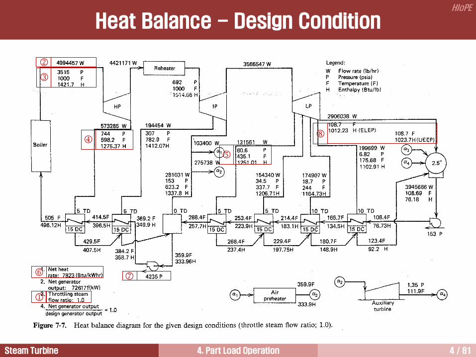
Heat Balance - Design Condition
Steam Turbine 4. Part Load Operation 5 / 81
HIoPE
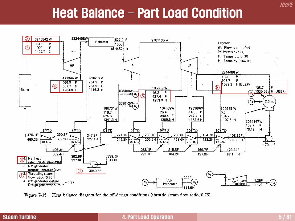
Heat Balance – Part Load Condition

Steam Turbine 4. Part Load Operation 6 / 81
HIoPE
HP Turbine LP Turbine
MS R
100% Power
75% Power
50% Power
25% Power
Pre
ssure
C/V
A Basic Concept for Part Load Operation

Steam Turbine 4. Part Load Operation 7 / 81
HIoPE
Output and Efficiency at Part Load
49.0
48.3
47.6
46.9
46.2
45.5
44.8
44.1
43.4
42.7
42.0
45 50 55 60 65 70 75 80 85 90 95 100
200
500
470
440
410
380
350
320
290
260
230
Load, %
Effic
iency,
%
Pow
er,
M
W
Power
Efficiency
Example: 460 MW, supercritical power plant
Output and Efficiency at Part Load

Steam Turbine 4. Part Load Operation 8 / 81
HIoPE
A turbine has different expansion lines as the load is
decreased.
But the part load expansion lines are generally parallel
to the full load expansion line.
This means that the internal efficiency under part load
conditions is very close to that under full load
conditions. That is, design efficiency of the turbine
blades is maintained during part load operations by
using the control valve.
However, the cycle efficiency is reduced under part
load conditions.
Throttling Process
p1
Ava
ilab
le E
ne
rgy
pc
p0
T0
h
s
Partial-flow expansion line
Expansion lines are
essentially parallel
Design-flow expansion line
p1’
p0: Inlet pressure
p1: Throttle pressure 1 1′
2′
2
U 100% load
Nozzle Row
25% load
100%
25%
Bucket Row
U
75% load
50% load
[ Velocity Diagram at Various Loads ]
[ Effect of Throttling on Non-Reheat
Steam Turbine Expansion Line ]

Steam Turbine 4. Part Load Operation 9 / 81
HIoPE
1) Full throttling (= Single admission )
• Constant pressure mode
• Throttling by pressure reducing valves
• All control valves are activated at the same time
• This is the simplest way to control the power, but this gives a large throttle
(pressure) loss because of using the pressure throttle valves
2) Partial arc admission (Throttling by a control stage)
• Constant pressure mode
• Divided the first stage nozzle arc into several segments having its own control valve
• Lower throttle loss
• The control valves are activated in a sequential mode
3) Sliding (or variable) pressure operation
• Variable pressure mode
• Controlling throttle flow by varying boiler pressure
4) Hybrid operation
• A combination of partial arc admission and sliding pressure operation
4 Methods Used in Steam Flow Control
Control of Steam Flow in HP Turbines

Steam Turbine 4. Part Load Operation 10 / 81
HIoPE
Exhaust Loss during Part Load
AN
ANA
YmV
3600
01.01
= annulus velocity
= steam mass flow rate
= saturated dry specific volume
= annulus area
= percent of moisture at ELEP
ANV
m
ANA
Y
[Exercise 4.1]
부분부하운전 시 배기손실 크기 변화를 비교하시오. 아울러 그 결과를 heat balance에서 확인하시오.
0 500 1000 1500 2000
610 457 305 152 0
80
60
40
20
0
186
139
93
47
0 E
xhaust Loss, B
tu/lb
Exh
au
st L
oss, kJ/k
g
Annulus Velocity (VAN), ft/s
Annulus Velocity (VAN), m/s
Thermodynamic
Optimum
Economic
Optimum
Total
Exhaust
Loss
Axial
Leaving
Loss
VAN proportional to:
rating
1/exhaust pressure
1/exhaust area

Steam Turbine 4. Part Load Operation 11 / 81
HIoPE
Partial Arc Admission 4
Hybrid Operation 6
Basics for the Control of Steam Flow 1
Full Throttling 3
Sliding Pressure Operation 5
Valves 2
Load Changes 8
Startup System of Steam Power Plants 7

Steam Turbine 4. Part Load Operation 12 / 81
HIoPE
Valves
[ A Typical Power Plant Steam Flow Diagram ]
Gen
Stop V/V
Control V/V
HP IP LP
Condenser
Reheater
Reheat
Stop and
Intercept
V/V
Main Steam
Hot Reheat
Cold
Reheat
Crossover
Ventilation
V/V
Exciter
Steam
Generator
Front
Standard
Steam Turbine 4. Part Load Operation 13 / 81
HIoPE
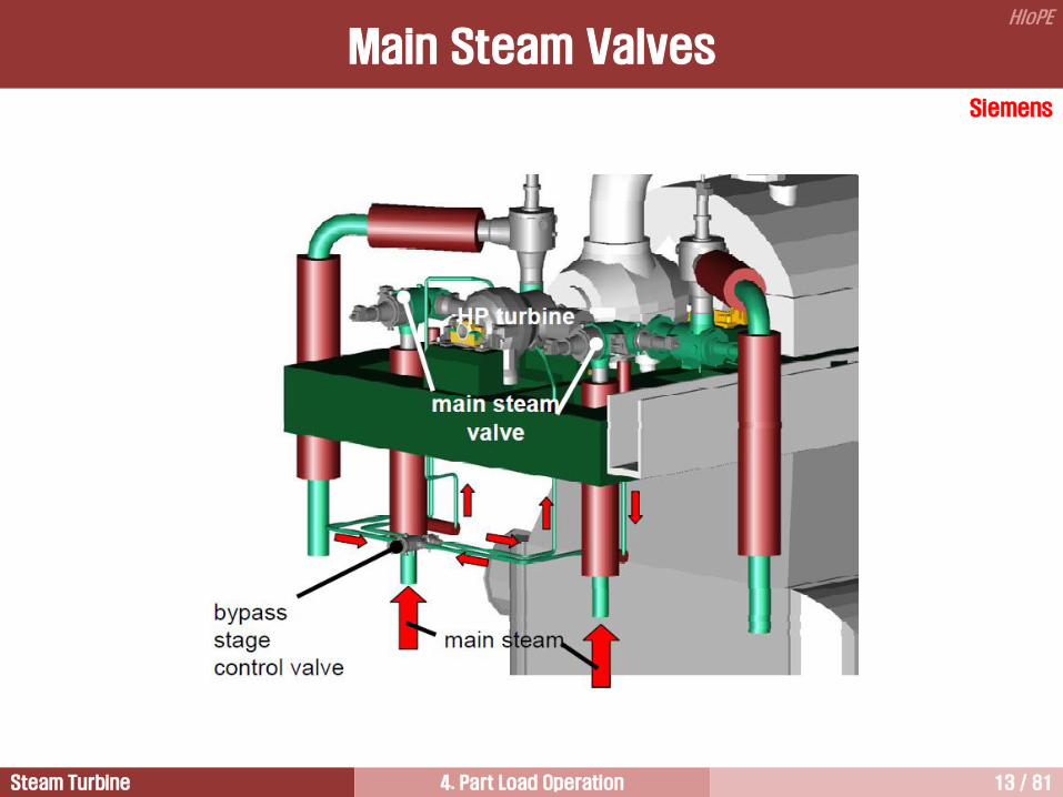
Main Steam Valves
Siemens

Steam Turbine 4. Part Load Operation 14 / 81
HIoPE
Typical Individual Stop and Control Valve Assembly
Valve 개수(표준화력 500MW 기준) - Stop v/v : 2 - Control v/v : 4 Stop valve = on-off valve Control valve = throttle valve라고도 불리며, load 연동 Typical closing time during emergency - Stop v/v : 0.09초 10% - Control v/v : 0.11초 10%
Generals
MSV
MCV
Actuator
Actuator
GE
Steam Turbine 4. Part Load Operation 15 / 81
HIoPE
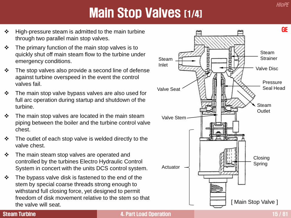
Main Stop Valves [1/4]
High-pressure steam is admitted to the main turbine
through two parallel main stop valves.
The primary function of the main stop valves is to
quickly shut off main steam flow to the turbine under
emergency conditions.
The stop valves also provide a second line of defense
against turbine overspeed in the event the control
valves fail.
The main stop valve bypass valves are also used for
full arc operation during startup and shutdown of the
turbine.
The main stop valves are located in the main steam
piping between the boiler and the turbine control valve
chest.
The outlet of each stop valve is welded directly to the
valve chest.
The main steam stop valves are operated and
controlled by the turbines Electro Hydraulic Control
System in concert with the units DCS control system.
The bypass valve disk is fastened to the end of the
stem by special coarse threads strong enough to
withstand full closing force, yet designed to permit
freedom of disk movement relative to the stem so that
the valve will seat.
GE
Steam
Inlet
Steam
Strainer
Valve Seat
Valve Stem
Valve Disc
Steam
Outlet
Pressure
Seal Head
Actuator
Closing
Spring
[ Main Stop Valve ]

Steam Turbine 4. Part Load Operation 16 / 81
HIoPE
The steam from the steam generator flows to the main steam stop or throttle valves.
The primary function of the stop valves is to provide backup protection for the steam turbine during turbine
generator trips in the event the main steam control valves do not close.
The energy contained in the main steam can cause the turbine to reach destructive overspeed quickly when
generator loose the load.
The main stop valves close from full open to full closed in 0.15 to 0.5 s.
The main stop valves are closed on unit normal shutdown after the control valves have closed.
A secondary function of the main stop valves is to provide steam throttling control during startup.
The main stop valves typically have internal bypass valves that allow throttling control of the steam from
initial turbine roll to loads of 15% to 25%.
During this startup time, the main steam control valves are wide open and the bypass valves are used to
control the steam flow.
Some recent and current designs do not have these bypass valves.
Initial turbine speed runup is controlled by the main stop valves.
Main Stop Valves [2/4]

Steam Turbine 4. Part Load Operation 17 / 81
HIoPE
The bypass valve is held in the valve disk by a
bolted cap. Holes are located in the cap for steam
entrance, and holes in the valve disk pass the
steam when the bypass valve is utilized.
When the stop valve is opened the bypass valve
opens first as the valve stem moves in the open
direction.
When the bypass valve is fully open it contacts a
bushing on the stop valve and pulls it open. When
the stop valve is fully open, a bushing seats on the
inner end of the valve stem bushing and prevents
steam leakage along the valve stem.
Main Stop
Valve Stem
Main Stop
Valve Disc
Seating
Surface
Main Stop
Valve Disc
Bypass
Valve Disc
Bypass
Valve Ports
(8 ea)
[ Stop Valve Bypass ]
Each stop valve has two steam leakoff points where the stop valve stem passes through the stop valve
casing.
The first leakoff point located closest to the stop valve is referred to as the high-pressure leakoff and is
routed to the steam seal header.
During startup or low loads steam is supplied to this leakoff to assure a seal. After the turbine is loaded,
steam is fed through this line from the stop valve stem into the steam seal header.
The second leakoff point is referred to as the low-pressure leakoff and is routed to the gland steam
condenser.
Bypass Valve GE
Main Stop Valves [3/4]

Steam Turbine 4. Part Load Operation 18 / 81
HIoPE
Bypass Valve
Main Stop Valves [4/4]

Steam Turbine 4. Part Load Operation 19 / 81
HIoPE
The steam from the stop valves flows to the
main steam control or governor valves.
The primary function of control valves is to
regulate the steam flow to the turbine and thus
control the power output of the steam turbine
generator.
The control valves also serve as the primary
shutoff the steam to the turbine on unit normal
shutdowns and trips.
MHI
Main Steam Control Valves [1/3]
MSV
MCV
Actuator
Actuator
Siemens
Steam from
No.1 C/V
Steam from
No.3 C/V
Steam from
No.4 C/V
Steam from
No.2 C/V
HP
Inner
Shell
HP
Inner
Shell
HP
Inner
Shell
HP
Inner
Shell Snout
Pipe
Seal
Rings
HP
Inner
Shell
HP
Inner
Shell
Snout Pipes
Snout Pipes
180 Degree Nozzle Box
180 Degree Nozzle Box
Upper
Lower
Snout
Pipe
Seal
Rings

Steam Turbine 4. Part Load Operation 20 / 81
HIoPE
GE
The control valves regulate the steam flow to the turbine to
control the main turbine speed and/or load. The four control
valves are mounted in line on a common external valve chest.
Steam is supplied to the external valve chest through the main
stop valves. The valve chest is separated from the turbine, and
individual steam leads from the valve chest are provided from
each control valve to the inlet of the HP turbine. Each control
valve is operated by a hydraulic power actuator which positions
the control valves in response to signals from the Electro
Hydraulic Control System.
During startup, the control valves are wide open (full arc), and
the stop valves’ internal bypass valves control the steam flow to
the turbine. Under these conditions, steam is admitted through
all four steam leads around the entire periphery of the HP
turbine inlet. The purpose of this full arc admission is to reduce
thermal stresses caused by unequal steam flow through the
nozzle sections. During full arc admission, throttling of the
steam occurs at the stop valve bypass valves only, and there is
uniform steam flow into the HP turbine. This also results in
lower steam velocities at the turbine inlet. Because of the lower
steam velocities the temperatures cannot change as rapidly.
Full arc admission is used until the high transfer point is
reached, at which time transfer to partial arc will occur. [ Main Steam Control Valve ]
Closing
Spring
Balance
Chamber
Valve
Seat Valve
Disc
Steam
Chest
Main Steam Control Valves [2/3]

Steam Turbine 4. Part Load Operation 21 / 81
HIoPE
During normal operation, the main stop valves are wide open and the control valves control steam flow to
the turbine. The control valves operate sequentially to control steam flow to the turbine and the unit load.
All four control valves are never open the same amount for any given load up to full load with wide-open
control valves. This is referred to as partial arc admission.
Transfer to partial arc admission is normally automatically performed by the low transfer and high transfer
micro- switches but may also be initiated by the operator when the OK TO TRANSFER light comes on.
The control valves are throttled until they have control of steam flow and the stop valves then automatically
run full open.
Number l and 2 control valves are balanced type, with internal pilot valves. Number 3 and 4 control valves
are unbalanced single disk type.
The balanced type valves are equipped with an internal pilot valve connected to the valve stem. When
opening, the pilot valve is opened first to equalize the pressure across the main valve disk. Further opening
of the stem opens the main disk.
The disk of the unbalanced type valve is directly connected to the stem.
Each control valve is provided with two steam leakoff points where the control valve stem passes through
the external steam chest wall. The first leakoff point located closest to the external steam chest is referred to
as the high-pressure leakoff and is routed to the hot reheat steam line. The second leakoff point is referred
to as the low-pressure leakoff and is routed to the steam seal header.
GE
Main Steam Control Valves [3/3]

Steam Turbine 4. Part Load Operation 22 / 81
HIoPE
Reheat Stop and Intercept Valves [1/4]
[ Combined Reheat Stop and Intercept Valve, GE ]

Steam Turbine 4. Part Load Operation 23 / 81
HIoPE
Balance
Chamber
Intercept
Disc Reheat
Stop Disc
Steam Out
Steam
In
Intercept
Actuator
Closing
Spring
Reheat Stop
Actuator
Steam
Strainer
GE Two combined reheat stop and intercept
valves are provided, one in each hot
reheat line supplying reheat steam to the
IP turbine.
As the name implies, the combined
reheat intercept valve is actually two
valves, the intercept valve (IV) and the
reheat stop valve (RSV), incorporated in
one valve casing.
Although they utilize a common casing,
these valves have separate operating
mechanisms and controls.
The function of the intercept valves and
reheat stop valves is to protect the
turbine against overspeed from stored
steam in the reheater.
[ Reheat Stop and Intercept Valves (SKODA) ]
Reheat Stop and Intercept Valves [2/4]

Steam Turbine 4. Part Load Operation 24 / 81
HIoPE
The intercept valve disk is located above the reheat stop valve disk, with its stem extending through the
upper head. The reheat stop valve stem extends downward through the below-seat portion of the casing.
Both valves share a common seat; however, the intercept valve is designed to travel through its full stroke
regardless of the reheat stop valve position, while the intercept valve must be in the “closed” position for the
reheat stop valve to open.
During normal operation of the turbine-generator unit, the intercept valves are fully open.
The purpose of the intercept valve is to shut off steam flow from the reheater, which, because of its large
storage capacity, could possibly drive the unit to overspeed upon loss of generator load.
The intercept valve is capable of reopening against maximum reheat pressure and of controlling turbine
speed during reheater blowdown following a load rejection.
The primary function of the reheat stop valves is to provide a second line of defense (backup protection)
against the energy storage of the reheater in the event of failure of the intercept valves or the normal control
devices.
However, note that the reheat stop valves also close upon a routine shutdown, or by operation of certain
boiler and electrical trips whenever the main stop valves are closed.
The reheat stop valve power actuators are sized so that the reheat stop valves are capable of reopening
against a steam pressure differential of approximately 15 percent of maximum reheat pressure.
Reheat Stop and Intercept Valves [3/4]

Steam Turbine 4. Part Load Operation 25 / 81
HIoPE
The function of the reheat stop and intercept valves is similar to the main steam stop and control valves.
The reheat stop valve offer backup protection for the steam turbine in the event of a unit trip and failure of
the intercept valves to close.
The intercept valves control unit speed during shutdowns and on large load changes, and protect against
destructive overspeeds on unit trips.
The need for these valves is a result of the large amount of energy available in the steam present in the HP
turbine, the hot and cold reheat lines, and the reheater.
On large load changes, the main steam control valves start to close to control speed, however, energy in the
steam present after the main steam control valves may be sufficient to cause the unit to overspeed.
The steam after the main steam control valves could expand through the IP and LP turbines to the
condenser, supplying more power output than is required, causing the turbine to overspeed.
The intercept valves are used to throttle the steam flow to the IP turbine in this situation to control turbine
speed.
During unit shutdowns, a similar situation could occur, and the intercept valves are used to control speed
under these conditions as for the trip condition.
During unit trips, both the reheat stop and the intercept valves close, preventing the reheat-associated steam
from entering the IP turbine.
During normal unit operation, the reheat stop and intercept valves are wide open, and load control is
performed by the main steam valves only.
Reheat Stop and Intercept Valves [4/4]

Steam Turbine 4. Part Load Operation 26 / 81
HIoPE
During unit trips, the closure of the main stop and control valves and of the
reheat stop and intercept valves traps steam in the HP turbine.
During the turbine overspeed and subsequent coastdown, the HP turbine
blades are subject to windage losses from rotating in this trapped steam.
The windage losses cause the blades to be heated.
This heating, in combination with the overspeed stress, can damage the HP
turbine blades.
To prevent this, a ventilation valve is provided to bleed the trapped steam to
the condenser.
On a unit trip, the valve is automatically opened.
The bleeding action causes the trapped steam to flow through the HP turbine,
maintaining the HP turbine temperature within acceptable limits by preventing
heat buildup from the windage losses.
Ventilation Valve
[ Ventilation Valve, CCI ]

Steam Turbine 4. Part Load Operation 27 / 81
HIoPE
Stop V/V
Control V/V
HP IP LP Gen
Condenser
Reheater Reheat Stop and
Intercept V/V
Main Steam
Hot Reheat
Cold
Reheat
Crossover
Ventilation
V/V
HRH bypass station
(HRH: Hot Reheat)
HP
byp
ass
sta
tio
n
[ Turbine Bypass Diagram ]
Ventilation Valve

Steam Turbine 4. Part Load Operation 28 / 81
HIoPE
0.2 0.4 0.6 0.8 1.0
2
4
6
8
Equivalent throttle flow ratio
Th
rott
le to
bo
wl p
ressu
re d
rop
(%
)
Pressure Drop in Valves
The efficiency of a steam turbine is governed by the efficiency of the individual stages and the pressure
drop through valves, cross-over pipes, and exhaust hoods.
Throttle steam from the boiler first pass through the stop valve and then control valves.
The stop valve pressure
drop is 2% and the control
valves in the wide open
position also have a
pressure drop of 2%.
Therefore, total pressure
drop occurred in the
valves is 4%.
The total loss in overall
heat rate of these pressure
drops is about 0.4%.

Steam Turbine 4. Part Load Operation 29 / 81
HIoPE
Partial Arc Admission 4
Hybrid Operation 6
Basics for the Control of Steam Flow 1
Full Throttling 3
Sliding Pressure Operation 5
Valves 2
Load Changes 8
Startup System of Steam Power Plants 7

Steam Turbine 4. Part Load Operation 30 / 81
HIoPE
All control valves have a same position in full throttling operation
Control V/V
(1.5% p @ VWO)
Nozzle
First stage
shell pressure
Stop V/V
(1.5% p)
Bucket
Steam
Flow
#1
#2
#1
#2
#3
#4
Concept of Full Throttling

Steam Turbine 4. Part Load Operation 31 / 81
HIoPE
Generals for Full Throttling
Load
Ahead of First
Stage Nozzles
(Bowl Pressure)
After First Stage
(Shell Pressure)
Initial (Main Steam)
Throttling 0 Steam condition entering the control valves
1 Steam condition entering the first stage
2 Steam condition entering the second stage
0
h
s
1
p0 p1
p2
2

Steam Turbine 4. Part Load Operation 32 / 81
HIoPE
Full throttling is the simultaneous operation of all main steam control valves at the same time.
The main steam supplied during part load operation has a same pressure with that supplied during full load
operation.
Therefore, throttling loss is occurred whenever the plant is operated with part load.
The steam turbine output increases as the valves are opened and full load is reached when the valves are
wide open.
During the part load operation, full throttling is the least efficient of all control modes because the available
energy in the expansion process is reduced greatly by the throttling process. For this reason, the HP turbine
with full throttling has a greater entropy increase than that with partial arc admission.
This method is also called as ‘full arc admission’, ‘single admission’, or ‘throttling control’ because of the
steam admission to all portions of the control stage.
During the startup of some units, the control valves are wide open.
Steam is initially admitted to the turbine by throttling the steam flow by using the bypass valves internal to
the main steam stop valves.
This flow control method is used up to 15% to 25% load.
Above this load, the main steam control valves are used to control the steam flow and the main steam stop
valves are wide open.
The complex control stage design is not required.
Generals for Full Throttling

Steam Turbine 4. Part Load Operation 33 / 81
HIoPE
For 50% reaction turbines with throttling control, the pressure ratio across the first stage is about 1.13 at all
loads.
This value of pressure ratio is too low to produce sonic velocity.
Thus, an advantage of throttling control is no solid particle erosion in the first stage.
The solid particle erosion would be in the control valves, which are less expensive to repair than the first
stage.
Another advantage of throttling control is lower stress levels due to low first stage velocities and the absence
of inactive arcs.
Advantages of Full Throttling

Steam Turbine 4. Part Load Operation 34 / 81
HIoPE
Ab
so
lute
ste
am
pre
ssu
re
[ Variation of stage-shell pressure ]
m1
m0
Stage pressure is roughly proportional to the mass flow
rate to the following stage, the throttle flow minus
leakages, and all extractions from the preceding stages
and stage in question, plus any steam returned to the
turbine ahead of this stage.
Therefore, mathematical relationship is
di
idii
m
mpp
,
,
= steam pressure at the nozzle of stage i
= design steam pressure at the nozzle of stage i
= steam mass flow rate to the stage i
= steam mass flow rate to the stage i
ip
dip ,
im
dim ,
Stage Pressure during Part Load

Steam Turbine 4. Part Load Operation 35 / 81
HIoPE
3566457 lb/hr
131561 lb/hr
60.6 psia
LP Turbine
2701136 lb/hr
105869 lb/hr
46.21 psia
LP Turbine
[Exercise 4.1]
아래 그림은 각각 설계조건과 부분부하운전조건에서 LP터빈 첫 번째 추기 지점에서의 조건이다. 부분부하운전조건에서 추기압력을 계산하고 검토하시오.
[ Full load ] [ Part load ]
Stage Pressure during Part Load

Steam Turbine 4. Part Load Operation 36 / 81
HIoPE
[Solution]
Design conditions are
pd = 60.6 psia
md = 3,566,547131,561 = 3,434,986 lb/hr
md means the steam mass flow rate to the next stage.
Under the part load conditions this mass flow rate becomes
m = 2,701,136105,869 = 2,595,267 lb/hr
Extraction pressure can be calculated
p = 606.6 2,595,267/ 3,434,986
= 45.8 psia
This calculated pressure is very close to extraction pressure shown in heat balance, 46.21 psia.
di
idii
m
mpp
,
,
Stage Pressure during Part Load

Steam Turbine 4. Part Load Operation 37 / 81
HIoPE
Partial Arc Admission 4
Hybrid Operation 6
Basics for the Control of Steam Flow 1
Full Throttling 3
Sliding Pressure Operation 5
Valves 2
Load Changes 8
Startup System of Steam Power Plants 7

Steam Turbine 4. Part Load Operation 38 / 81
HIoPE
Concept of Partial Arc Admission
Control V/V
(1.5% p @ VWO)
Nozzle
First stage
shell pressure
Fully Open
Stop V/V
(1.5% p)
Partially Open
Closed
Bucket
#1
#2
#3
#4
Steam
Flow
#1
#2 Closed

Steam Turbine 4. Part Load Operation 39 / 81
HIoPE
Nozzle Box
43
43
42
42
#1
#2 #4
#3
Number of nozzle
Turbine C.W.
[ 500 MW (3,500 psig, 1,000F) ]

Steam Turbine 4. Part Load Operation 40 / 81
HIoPE
Full Arc (Single Admission)
Partial Arc
The dimensions of turbine blades and flow channels are primarily a function of the volumetric
flow rates passing through the machine
Inactive
arc
#1 v/v
#2 v/v #4 v/v
#3 v/v #1 v/v
#2 v/v #4 v/v
#3 v/v
Concept of Partial Arc Admission

Steam Turbine 4. Part Load Operation 41 / 81
HIoPE
Pressure Variation
Full
Arc Partial
Arc
Load
Ahead of
Nozzle
Box #1
Ahead of
Nozzle
Box #2
Ahead of Nozzle Box #3
Ahead of
Nozzle
Box #4
After First Stage
Initial (Main
steam
pressure)
Load
Ahead of First Stage
Nozzles (Bowl
Pressure)
After First Stage
(Shell Pressure)
Initial (Main steam pressure)
Throttling

Steam Turbine 4. Part Load Operation 42 / 81
HIoPE
Generals for Partial Arc Admission
The inlet annulus area of the first stage nozzle is divided into several segments (vary from 4 to 6 to 8) along
tangential direction.
Typically, the first stage divides the annulus into four to eight segments (arcs) having different angles
depending on the guarantee points.
Partial arc admission (PAA) is the sequential operation of the main steam control valves.
PAA varies the output of the steam turbine by increasing or decreasing the arc of admission of steam flow to
the turbine control (first) stage. (The first admission stage in steam turbines often referred to as governing or
control stage)
Each control valve feeds a separate segment of the control stage, and the amount of arc in use is
determined by the number of valves open.
The valves are opened in a particular order that is determined by the allowable stresses on the control stage.
PAA is also called as governing control.
Rated throttle conditions are used throughout the load range to the extent allowed by the steam generator.
- to be continued -

Steam Turbine 4. Part Load Operation 43 / 81
HIoPE
The first stage is of impulse design because it gives only a small circumferential pressure gradient after
nozzle so the spreading of the jets circumferentially may be attenuated. For the 50% reaction turbine, the
first stage is the same as for the impulse turbine.
Partial arc admission can cause high impulse loads on the nozzle and buckets, possibly leading to high cycle
fatigue failures.
If the partial arc admission is applied for small turbine, the blade height can be increased in order to increase
stage efficiency.
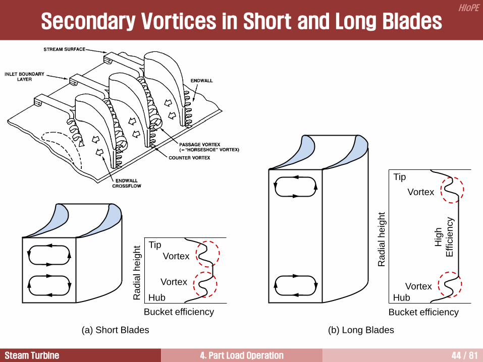
Normally, entropy production becomes higher for small turbines than large machines. This is because of
higher endwall losses for shorter blades, and the substantial part of the endwall losses caused by the
secondary flow formed in both nozzle and bucket row.
One way to prevent this is to increase the dimension of the turbine blades and adopt partial admission. Even
though extra losses due to the employment of partial admission is introduced, it might be beneficial due to
the decreased endwall losses.
Generals for Partial Arc Admission
Steam Turbine 4. Part Load Operation 44 / 81
HIoPE
Secondary Vortices in Short and Long Blades
(a) Short Blades (b) Long Blades
Hub
Tip
Vortex
Vortex
Ra
dia
l h
eig
ht
Bucket efficiency
Hub
Tip
Vortex
Vortex
Ra
dia
l h
eig
ht
Bucket efficiency
Hig
h
Effic
ien
cy

Steam Turbine 4. Part Load Operation 45 / 81
HIoPE
Advantages of Partial Arc Admission
PAA is more efficient than full throttling because the throttling
process loss is minimized by reducing the number of control
valves throttling at any one time.
If the PAA is employed, the inlet flow rate can be controlled
and a high inlet pressure and temperature can be maintained
as high as for the fully admitted arcs, even for low flow rates.
Considerably less pressure is lost due to throttling by PAA so
that more pressure is available to produce power in the first
stage, with a corresponding improvement in overall heat rate.
Inactive
arc
#1 v/v
#2 v/v #4 v/v
#3 v/v

Steam Turbine 4. Part Load Operation 46 / 81
HIoPE
Comparison of Throttling Methods
(a) Full throttling (b) Partial arc admission
0
h
s
1
2a
p0 p1
p2
2b 2c
0
h
s
1
p0 p1
p2
2
0 1 Flow in the control valves
1 2b Flow across the first stage in an
arc segment
0 2a Flow across the first stage in
the fully opened segments
2c Steam condition into the
second stage
0 Steam condition entering the control
valves
1 Steam condition entering the first
stage
2 Steam condition entering the second
stage

Steam Turbine 4. Part Load Operation 47 / 81
HIoPE
0 0.2 0.4 0.6 0.8 1.0
(VWO)
10
20
30
40
50
60
70
80
90
100
0
IP Turbine
LP Turbine
HP 2nd Stage to Cold Reheat
HP 1st Stage
Throttle Flow Ratio
Effic
iency [%
]
Turbine Section Efficiency

Steam Turbine 4. Part Load Operation 48 / 81
HIoPE
0 0.2 0.4 0.6 0.8 1.0
(VWO)
55
60
65
70
80
85
90
Throttle Flow Ratio
HP
Turb
ine E
ffic
iency [%
]
HP Turbine Efficiency
75
Full Throttling
Partial Arc
Admission

Steam Turbine 4. Part Load Operation 49 / 81
HIoPE
Heat Rate
Actual turbine cycle performance is shown on a
valve loop basis heat rate curve.
This curve reflects the steam throttling effect as
the steam passes through a partially closed
steam admission.
The throttling pressure drop reduces the
available energy of the steam as the throttled
admission steam expands across the control
stage.
An alternative method of representing turbine
heat rate impact due to turbine valve losses at
part load is by a mean of valve loop method.
Generator output
He
at ra
te
40 0 20 60 80 100
Valve Loop Basis (True Curve)
Mean of Valve Loop Basis
Valve Point Basis
(Locus-of-valve best points)
This method is an approximation of the heat rate impact illustrated on the valve loop basis curve and
represents a mean of the turbine heat rate and passes through the valve loop curve.
Turbine heat balance developed on the basis of this assumption are considered to be on a locus-of-valve
best points basis. This heat balances describe heat rates assuming an infinite number of small valves
having a 3% pressure drop.

Steam Turbine 4. Part Load Operation 50 / 81
HIoPE
Partial Admission
The control stage should be designed with
impulse turbine in order to avoid circumferential
flow of steam after passing through the first
stage nozzle

Steam Turbine 4. Part Load Operation 51 / 81
HIoPE
0.3
60
Velocity Ratio [U/C]
HP
Turb
ine E
ffic
iency [%
]
50
70
80
0.4 0.5 0.6
A
B C
D
E
F = 85/170
A
B
C
D
E
Efficiency at Partial Arc Admission

Steam Turbine 4. Part Load Operation 52 / 81
HIoPE
Stagnation Region Stagnation
Region
Sector-End Loss Axial
Tangential Ventilation Loss
Partial Admission Losses

Steam Turbine 4. Part Load Operation 53 / 81
HIoPE
Tangential Blade Force under Partial Arc Admission
over Time
The large unsteady forces acting on the buckets in tangential
direction are produced when the buckets enter and leave the
admission jets
Time
0 2 4 6 8
t=0
t=1 Tref
t=2 Tref
t=6 Tref
t=7 Tref
t=8 Tref
10
0.00
- 0.05
- 0.10
0.05
0.10
0.15
0.20
0.25
0.30
Fo
rce
Actin
g o
n a
Bla
de
in
Tangential D
irection Unsteady Forces

Steam Turbine 4. Part Load Operation 54 / 81
HIoPE
• It can employ longer blades which give better
aerodynamic turbine efficiency.
• It gives smaller entropy increase during part
load operation.
• Therefore, the HP turbine efficiency is better
during part load operation.
• The better part load performance for partial
admission must be balanced against the
increased potential for high cycle thermal
fatigue in the first stage.
• The first stage is called as governing stage or
control stage.
Partial Arc Admission Single Admission
• As load is decreased on the single admission
unit, an increasing amount of throttling takes
place in the control valves.
• It gives better efficiency than partial arc
admission at VWO because there is no inactive
arc.
• Many of the large nuclear units are designed full
throttling.
Partial Arc vs. Single Admission

Steam Turbine 4. Part Load Operation 55 / 81
HIoPE
The HP turbine efficiency is better during part
load operation with sequential valve operation
than throttling condition. However, at valve wide
open, the throttling controlled turbine gives better
performance. This is because single admission
has no inactive arc.
Comparison of HP Turbine Performance
Valve-loops are the result of changes in HP
turbine efficiency as the valve goes from closed to
fully open.

Steam Turbine 4. Part Load Operation 56 / 81
HIoPE
2400 psig/1000/1000F
4valves, first 3 valves open together
4valves, first 2 valves open together
Effect of Admission Modes
Single Admission (Full Throttling) +4
+3
+2
+1
0
1
20 30 40 50 60 70 80 90 100
% VWO Load
2 Admissions
3 Admissions
4 Admissions
1st 2nd 3rd v/v pt. VWO
Base Line is Locus of “Valve
Best Point” (Partial Arc
Admission)
Valve Loop
2

Steam Turbine 4. Part Load Operation 57 / 81
HIoPE
Partial Arc Admission 4
Hybrid Operation 6
Basics for the Control of Steam Flow 1
Full Throttling 3
Sliding Pressure Operation 5
Valves 2
Load Changes 8
Startup System of Steam Power Plants 7

Steam Turbine 4. Part Load Operation 58 / 81
HIoPE
Load
Ahead of First
Stage Nozzles
After First Stage
Main Steam
Load
Ahead of First
Stage Nozzles
After First Stage
Main Steam
[ Full Throttling ] [ Sliding Pressure Operation ]
Sliding Pressure Operation
Comparison with Full Throttling

Steam Turbine 4. Part Load Operation 59 / 81
HIoPE
Generals for Sliding Pressure Operation
In a sliding pressure operation mode, which is also called as variable pressure operation, the steam flow is
controlled by varying boiler pressure with the main steam control valves are always fully open. Therefore, no
throttling occurs and control stage is not needed.
The steam pressure is proportional to the load, not only within the turbine but also as the inlet to the turbine
(main steam line), and in the steam generator.
Main steam pressure is controlled by the boiler firing rate.
The main advantage of sliding pressure operation is that the main steam temperature remains relatively
constant across the load range which shortens startup times and increases turbine rotor life.
The disadvantages of sliding pressure operation are poorer thermodynamic efficiency and limited load
response capability.
It may require a forced circulation boiler to have a fast response capability.
A sudden load increase is not possible because all control valves are always fully open.
The lower main steam pressures of this operating mode result in less available energy than in the partial arc
admission operation, but more than in the full throttling operation.
Both feed pump power and throttling losses in the turbine control valves can be reduced during the sliding
pressure operation because of lower pressure.

Steam Turbine 4. Part Load Operation 60 / 81
HIoPE
Sliding pressure operation has a reduced
thermodynamic efficiency during part load
operation because of reduced available energy
caused by reduced boiler pressure.
However, there are two important facts to be
considered in terms of efficiency of plant. Firstly,
boiler feedwater pump power at low load
operation with variable pressure can be
reduced significantly. Secondly, the moisture
loss at low load operation with variable pressure
can be reduced. These two facts contribute to
increase efficiency of the plant.
T
s
2
1
2
3
a b
4
b
4
3
increase in wnet
decrease in wnet
increase in qout
c
Generals for Sliding Pressure Operation

Steam Turbine 4. Part Load Operation 61 / 81
HIoPE
Items 결과 이유 효율변화
밸브 교축손실 모든 출력에서 VWO상태이기 때문에 교축손실 매우 작음
HP Turbine 효율 HP 1단에서 full arc 운전이며, 밸브에서 교축손실 작음
Rankine cycle 효율 부분부하운전에서 사이클 압력 저하로 available energy 감소
급수펌프 동력 부분부하운전에서 펌프 동력 절감 (출력이 낮아질수록 보일러 운전압력이 낮아지기 때문에 펌프 동력 절감 크기 증대)
효율변화 분석

Steam Turbine 4. Part Load Operation 62 / 81
HIoPE
First S
tag
e E
xit T
em
pe
ratu
re
Throttle Flow
100% adm.
50% adm.
62.5% adm.
75% adm.
Sliding Pressure
Sliding Pressure
Partial Arc Admission
First Stage Shell Temperatures
Sliding pressure operation decreases the
potential for low cycle thermal fatigue in the
turbine during load changes as compared to
constant initial pressure operation.
In sliding operation, first stage exit
temperature is almost constant over the load
which reduces thermal stress.

Steam Turbine 4. Part Load Operation 63 / 81
HIoPE
Comparison of Heat Rate
Single Admission (Full Throttling) +4
+3
+2
+1
0
1
20 30 40 50 60 70 80 90 100
% VWO Load
2 Admissions
3 Admissions
4 Admissions
1st 2nd 3rd v/v pt. VWO
Constant Pressure
Sliding Pressure
2
Base Line is Locus of “Valve
Best Point” (Partial Arc
Admission)
Valve Loop

Steam Turbine 4. Part Load Operation 64 / 81
HIoPE
Partial Arc Admission 4
Hybrid Operation 6
Basics for the Control of Steam Flow 1
Full Throttling 3
Sliding Pressure Operation 5
Valves 2
Load Changes 8
Startup System of Steam Power Plants 7
Steam Turbine 4. Part Load Operation 65 / 81
HIoPE
% VWO Load
20 40 60 80 100
2400
2000
1000
600
3
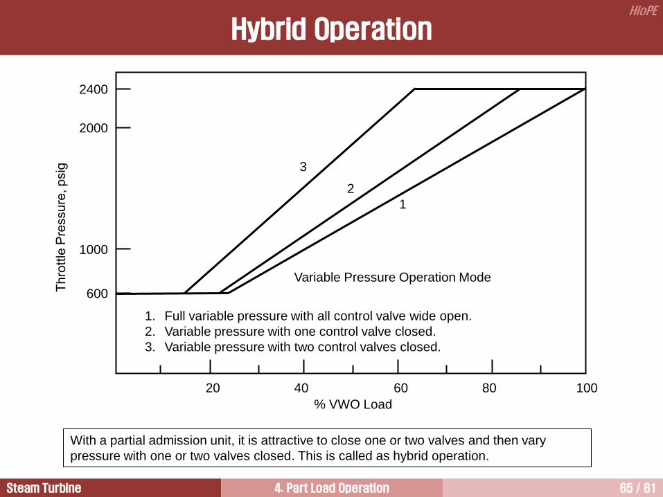
1. Full variable pressure with all control valve wide open.
2. Variable pressure with one control valve closed.
3. Variable pressure with two control valves closed.
2
1
Variable Pressure Operation Mode
Hybrid Operation
With a partial admission unit, it is attractive to close one or two valves and then vary
pressure with one or two valves closed. This is called as hybrid operation.

Steam Turbine 4. Part Load Operation 66 / 81
HIoPE
Korea Standard 500MW Fossil Power
분류 VWO MGR NR 75 50 30
Constant Pressure Operation Sliding Pressure Operation
출력 (kW) 550,000
(110%)
541,650
(108.3%)
500,000
(100%)
375,000
(75%)
250,000
(50%)
150,000
(30%)
유량 (lb/hr) 3,757,727
(112.7%)
3,684,046
(110.5%)
3,335,116
(100%)
2,389,835
(71.7%)
1,564,131
(46.9%)
980,271
(29.4%)
복수기 압력
(in.Hga) 1.5 1.5 1.5 1.5 1.5 1.5
주증기 온도 (F) 1000 1000 1000 1000 1000 1000
주증기 압력
(psia)
3514.7
(100%)
3514.7
(100%)
3514.7
(100%)
2860.2
(81.38%)
1870.2
(54.47%)
1152.6
(32.79%)
1st STA Bowl P.
(psia)
3409.3
(100%)
[97.00%]
3409.3
(100%)
[97.00%]
3409.3
(100%)
[97.00%]
2774.4
(81.39%)
[97.00%]
1814.7
(54.49%)
[97.03%]
1118.0
(32.79%)
[97.00%]
1st STA Shell P.
(psia)
2630.8
(113.9%)
2573.8
(111.5%)
2309.0
(100%)
1683.5
(72.9%)
1128.0
(48.9%)
723.9
(31.4%)
FWPT 동력 (kW) 18,755
(3.41%)
18,390
(3.40%)
16,611
(3.32%)
9,622
(2.57%)
4,125
(1.65%)
1,523
(1.02%)

Steam Turbine 4. Part Load Operation 67 / 81
HIoPE
Hybrid Operation
The hybrid operation adopts advantages of both sliding pressure operation and partial arc admission through
the combination of partial arc admission operation and sliding pressure operation.
Sliding pressure operation has the advantage of no throttling loss, and partial arc admission operation has
the advantage of fast load response.
At low loads, some of the main steam control valves are wide open and steam flow is controlled by sliding
pressure operation.
The main steam pressure is increased with steam turbine load until the main steam pressure rated
conditions.
The steam turbine load is increased further by maintaining the rated main steam pressure and sequential
opening of the remaining main steam control valve as in the partial arc admission operation.
Starting from full load, load reductions are initially achieved by closing control valves sequentially and
maintaining constant initial pressure.
When a particular valve point is reached, further load reductions are achieved by holding valve position
constant and decreasing initial pressure.
The best point for the change from constant to sliding pressure depends on the boiler characteristics and the
value of design initial pressure.
The optimum point usually occurs at about 50 to 60% load.
Steam Turbine 4. Part Load Operation 68 / 81
HIoPE
Hybrid Operation

Steam Turbine 4. Part Load Operation 69 / 81
HIoPE
Comparison of Heat Rate
Single Admission (Full Throttling) +4
+3
+2
+1
0
1
20 30 40 50 60 70 80 90 100
% VWO Load
2 Admissions
3 Admissions
4 Admissions
1st 2nd 3rd v/v pt. VWO
Constant Pressure
Sliding Pressure
1
2
3
2
Hybrid Operation
Base Line is Locus of “Valve Best
Point” (Partial Arc Admission) Valve Loop

Steam Turbine 4. Part Load Operation 70 / 81
HIoPE
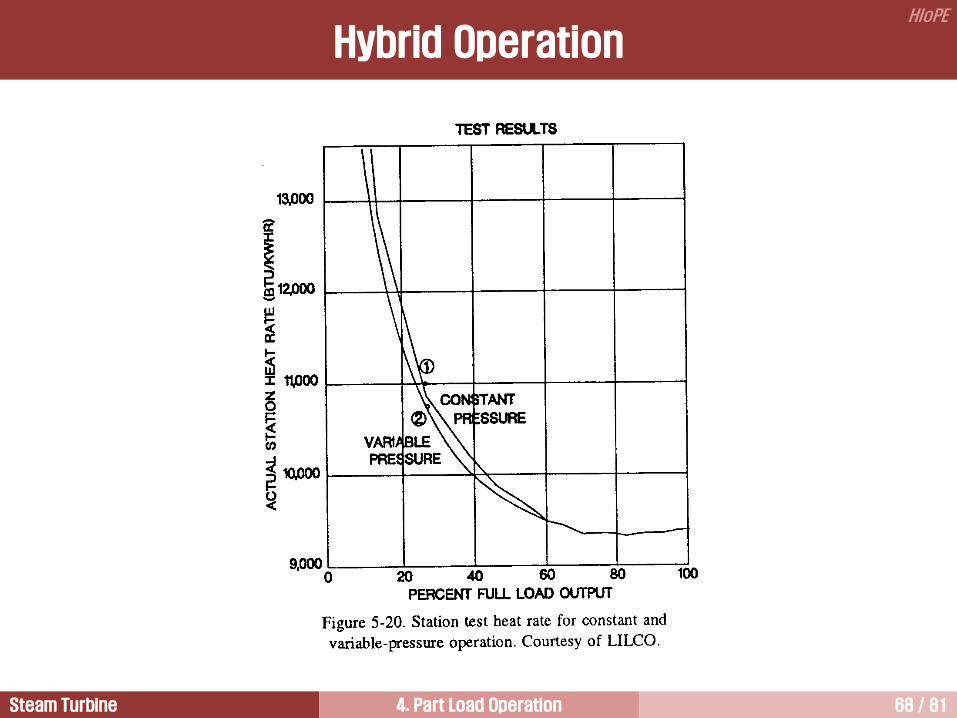
The full throttling has the worst overall heat rate because of throttling losses.
The sliding pressure operation has a slightly better heat rate than full throttling operation, but still has poor
performance because of the lower main steam pressures.
The partial arc admission operation shows the best heat rate at higher loads because of the high main steam
pressures and minimized throttling losses resulting from throttling with only one control valve at a time.
The hybrid operation gives the most efficient operation because the unit life is extended by maintaining
relatively constant temperatures at low loads, reducing cycling effects.
Heat rate for the partial arc admission is typically plotted as a “locus of best valve points,” that is, the line
passing through the heat rate points where any valves open are wide open.
The actual heat rate curve for the partial arc admission is represented by a valve loop that incorporates the
throttling losses associated with a valve throttling between full closed and full open.
Theoretically, the more control valves, the smaller valve loop, the greater the possibility of operating without
throttling, and the better the heat rate.
Comparison of Heat Rate

Steam Turbine 4. Part Load Operation 71 / 81
HIoPE
Modified Sliding Pressure Operation
Steam Turbine Load, %
Main
Ste
am
Pre
ssure
, %
0 20 40 60 80 100 0
25
50
75
100
• Today, modern power plants are operated in natural
sliding pressure mode or modified sliding pressure mode.
• Primary electrical power response (additional
electrical power within seconds) is produced by
condensate throttling.
• At a certain part load, the control valves can to be
throttled to improve the primary response capacity
Fixed Pressure Mode
Fixed Pressure
Mode
Modified sliding pressure operation uses throttle valve reserve so the valves are slightly closed at 90% to
95% load and some boiler stored energy can respond more quickly to rapid load change near full load.

Steam Turbine 4. Part Load Operation 72 / 81
HIoPE
Effect of Operating Mode on Steam Turbine Design

Steam Turbine 4. Part Load Operation 73 / 81
HIoPE
Partial Arc Admission 4
Hybrid Operation 6
Basics for the Control of Steam Flow 1
Full Throttling 3
Sliding Pressure Operation 5
Valves 2
Load Changes 8
Startup System of Steam Power Plants 7

Steam Turbine 4. Part Load Operation 74 / 81
HIoPE
Startup System of Steam Power Plants
Boiler-internal startup systems and unit startup system
The purpose of boiler-internal startup systems is to drain off the excess water discharged from the
evaporator and to ensure flow through once-through evaporators.
Excess water is defined as the quantity of water which must be removed from a water-filled heat-exchange
system due to increased volume as a result of steam formation and increased temperature.

Steam Turbine 4. Part Load Operation 75 / 81
HIoPE
Natural-circulation boilers only have equipment for removing the excess water from the drum.
During startup of once-through boilers, a circulation flow is combined with the once-through flow in the
economizer and evaporator until the minimum evaporator flow level.
The water that does not evaporate is separated from the steam in HP separators and then fed either to a
recirculation pump, a drain heat exchanger, the feedwater tank, or an atmospheric flash tank.
The unit startup system ensure cooling of the superheater heating surfaces and supplies steam to the
turbine at the required startup pressure and temperature.
In modern power plants, separate turbine bypass systems for the HP and IP/LP casings of the turbine,
respectively, are seeing increased use.
Essential advantages of this system are the result of the uniform heatup of the superheater heating surfaces
– preventing flaking of the protective coating on the inside of the tubes caused by thermal shock and
carryover of corrosion products into the turbine (solid particle erosion) – short startup time, and the same
basic startup procedure for cold, warm and hot starts.
If bypass systems are dimensioned appropriately ( 60% steam flow at full load), the steam generator can be
kept in operation even when there is a turbine-generator load rejection to the station auxiliary power level,
thus in most cases preventing a unit trip.
Startup System of Steam Power Plants

Steam Turbine 4. Part Load Operation 76 / 81
HIoPE
Partial Arc Admission 4
Hybrid Operation 6
Basics for the Control of Steam Flow 1
Full Throttling 3
Sliding Pressure Operation 5
Valves 2
Load Changes 8
Startup System of Steam Power Plants 7

Steam Turbine 4. Part Load Operation 77 / 81
HIoPE
Load Changes
Sudden loss of other power plants or grid disturbances require step increase of the load in those power
plants still on line of about 2 to 5% within seconds to maintain a stable grid frequency. Since it takes 2 to 3
minutes for increased firing in coal-fired units to achieve the desired electric power output, the storage
capacity of the water/steam system is used for making such step load changes. The various methods
applied vary with regard to dynamic behavior and economics:
1) Opening the control valves: A drop in pressure
upstream of the turbine activates the storage capacity
of the main steam line and the steam generator. The
magnitude of the possible load step increase
depends on the throttle setting on the turbine valves,
while the duration of the load step change depends
on the storage capacity. The storage capacity of a
drum boiler is about 2 to 3 times that of a once-
through boiler. On the other hand, the permissible
pressure transient is only 6 to 8 bar/min as apposed
to 20 to 30 bar/min for a once-through boiler. The
curve given in the figure depicts throttling
corresponding to 5% of the main steam pressure at
100% load.
Dynamic impact of various measures
taken to activate load reserves

Steam Turbine 4. Part Load Operation 78 / 81
HIoPE
2) Opening of multistage valve: With respect to the load step change, the behavior of the multistage valve is
similar to throttling of the turbine control valves. Compared to throttling of the turbine control valves,
however, the implementation of the multistage valve requires additional investment cost, but on the other
hand provides a lower heat rate in steady-state operation.
3) Condensate throttling: Reducing the condensate flow reduces the extraction-steam flow and therefore
increases the steam turbine output. A steam-side shutdown of the LP feedwater heaters is also possible
and makes the additional output available somewhat more quickly than does the throttling of the
condensate. The heat rate in steady-state operation is not affected by this measure, and only a small
additional investment is required.
4) Shutdown of HP feedwater heaters: This measure can be applied without duration restrictions. Initially,
however, it causes considerable thermal stress in the thick-walled components of the steam generator due
to the large feedwater temperature transients. In normal operation, the heat rate is not affected.
5) Increased injection flow into the steam generator: This measure primarily makes use of the thermal
storage capacity of the heating surfaces and the headers based on a reduction of steam temperature. The
heat rate in steady-state operation is not affected.
Load Changes

Steam Turbine 4. Part Load Operation 79 / 81
HIoPE
During load changes, temperature changes occur in the turbine and in the steam generator which cause
temporary thermal stresses in the thick-walled components and which thus limit the load transients. In the
HP turbine, the temperatures change on constant-pressure mode. In Fig. 3.49, the values are plotted
downstream of the first stage. In sliding-pressure mode, in which no throttling takes place, the temperatures
are nearly constant. Sliding-pressure mode is therefore the more favorable operating mode for the steam
turbine.
Load Changes

Steam Turbine 4. Part Load Operation 80 / 81
HIoPE
The temperature in the steam generator remain nearly constant in constant-pressure mode but change in
sliding-pressure mode due to the pressure-dependent saturated-steam temperature in the evaporator and
the primary superheater region. Moreover, a load increase in sliding-pressure mode as a result of increased
pressure stores energy in the system, which also reduces the load transients. For the drum-type boiler with
its thick-walled drum and the large storage capacity of the evaporator system, constant-pressure mode is
therefore the more favorable operating mode. The once-through boiler is well suited for either operating
mode.
Unit behavior under continuous load changes is determined by the two main components the boiler and the
turbine as well as the control system on the one hand, and by the operating mode on the other. Table 3.11
shows the feasible load transients for these two main components and the resulting unit values.
Load Changes

Steam Turbine 4. Part Load Operation 81 / 81
HIoPE
질의 및 응답
작성자: 이 병 은 (공학박사) 작성일: 2015.02.11 (Ver.5) 연락처: [email protected]
Mobile: 010-3122-2262 저서: 실무 발전설비 열역학/증기터빈 열유체기술